JP2005065819A - Steam cooker - Google Patents
Steam cooker Download PDFInfo
- Publication number
- JP2005065819A JP2005065819A JP2003297243A JP2003297243A JP2005065819A JP 2005065819 A JP2005065819 A JP 2005065819A JP 2003297243 A JP2003297243 A JP 2003297243A JP 2003297243 A JP2003297243 A JP 2003297243A JP 2005065819 A JP2005065819 A JP 2005065819A
- Authority
- JP
- Japan
- Prior art keywords
- steam
- outer container
- evaporator
- lid
- water
- Prior art date
- Legal status (The legal status is an assumption and is not a legal conclusion. Google has not performed a legal analysis and makes no representation as to the accuracy of the status listed.)
- Pending
Links
- 238000010438 heat treatment Methods 0.000 claims abstract description 61
- XLYOFNOQVPJJNP-UHFFFAOYSA-N water Substances O XLYOFNOQVPJJNP-UHFFFAOYSA-N 0.000 claims abstract description 58
- 235000013305 food Nutrition 0.000 claims description 15
- 238000010411 cooking Methods 0.000 claims description 10
- 238000001704 evaporation Methods 0.000 claims description 9
- 238000007599 discharging Methods 0.000 claims description 2
- 235000021186 dishes Nutrition 0.000 description 10
- 230000002093 peripheral effect Effects 0.000 description 9
- 239000011810 insulating material Substances 0.000 description 7
- 238000000034 method Methods 0.000 description 7
- 230000008020 evaporation Effects 0.000 description 6
- 238000001514 detection method Methods 0.000 description 5
- XAGFODPZIPBFFR-UHFFFAOYSA-N aluminium Chemical group [Al] XAGFODPZIPBFFR-UHFFFAOYSA-N 0.000 description 4
- 229910052782 aluminium Inorganic materials 0.000 description 4
- 239000004615 ingredient Substances 0.000 description 3
- 230000005855 radiation Effects 0.000 description 3
- 238000011084 recovery Methods 0.000 description 3
- 238000010025 steaming Methods 0.000 description 3
- 241000209094 Oryza Species 0.000 description 2
- 235000007164 Oryza sativa Nutrition 0.000 description 2
- 238000009835 boiling Methods 0.000 description 2
- 230000007423 decrease Effects 0.000 description 2
- 235000012054 meals Nutrition 0.000 description 2
- 235000009566 rice Nutrition 0.000 description 2
- 230000001427 coherent effect Effects 0.000 description 1
- 230000005494 condensation Effects 0.000 description 1
- 238000009833 condensation Methods 0.000 description 1
- 239000008236 heating water Substances 0.000 description 1
- 238000004519 manufacturing process Methods 0.000 description 1
- 239000000463 material Substances 0.000 description 1
- 235000013372 meat Nutrition 0.000 description 1
- 238000000465 moulding Methods 0.000 description 1
- 239000002245 particle Substances 0.000 description 1
- 230000000149 penetrating effect Effects 0.000 description 1
- 239000012466 permeate Substances 0.000 description 1
- 229920006395 saturated elastomer Polymers 0.000 description 1
- 238000007789 sealing Methods 0.000 description 1
- 235000013547 stew Nutrition 0.000 description 1
- 239000008400 supply water Substances 0.000 description 1
- 235000019640 taste Nutrition 0.000 description 1
Images



Landscapes
- Commercial Cooking Devices (AREA)
- Cookers (AREA)
Abstract
Description
本発明は、焼売や茶碗蒸し等の蒸し料理等を扱うホテルやレストラン等において、お客が自分のテーブルで加熱したての料理を食することができるよう、また好みに合わせてお客が調理可能なよう、各々の食卓テーブル及びカウンターテーブル等に組み込んで使用するのに適した蒸気加熱調理器に関する。 The present invention enables customers to eat freshly cooked dishes at their tables at hotels and restaurants that handle steamed dishes such as pottery and steamed rice bowls, and also allow customers to cook according to their tastes. The present invention relates to a steam heating cooker suitable for use in each table and counter table.
ホテルやレストラン等において前記のような蒸し料理を客の食に提供する場合、厨房で蒸し終えた料理をウエイター等がワゴン等に乗せて客席のテーブルへ運び、そこでお客のテーブル上に配膳して客の食に提供するという形態が従来において最も一般的に行われていた。 When providing steamed dishes like the above to guests' meals at hotels, restaurants, etc., waiters etc. put the dishes that have been steamed in the kitchen on wagons etc. and carry them to the table of the customer seat, where they are served on the customer's table In the past, it was most commonly performed to provide food for customers.
しかし、蒸し終えた料理を客のテーブルまでウエイターが運ぶ場合に、ウエイターが取り扱える程度にまでセイロの温度が低下していることが条件となる。加えて、ワゴン等に乗せて運んでいる間にせいろ及び内部の料理の温度が低下し、客のテーブルへ配膳する時点では料理の温度がかなり低下してしまう。 However, when the waiter carries the steamed dish to the customer's table, the condition is that the temperature of the salo has fallen to such an extent that the waiter can handle it. In addition, the temperature of the dishes and the inside dishes are lowered while being carried on a wagon or the like, and the temperature of the dishes is considerably lowered at the time of serving to the customer's table.
また、レストランの経営という観点から考えた場合、熱いセイロを運んで客のテーブルに配膳するウエイターの手数も無視することは出来ず、人件費の問題もある。
このようなことから、ホテルやレストラン等において、客の来店時に、客のテーブルにおいて料理を蒸し上げ、その場で蒸したての料理を客の食に提供したいという要望が強い。そこで、このような目的に従い、幾つか卓上蒸し器が開発され、これまでにも使用されている。
Also, from the viewpoint of restaurant management, the number of waiters carrying hot salos and serving customers' tables cannot be ignored, and there is a problem of labor costs.
For this reason, there is a strong demand in hotels, restaurants, and the like for steaming dishes on the customer's table and providing freshly steamed dishes to the customer's meal when the customer visits the store. Therefore, several tabletop steamers have been developed and used so far according to such a purpose.
従来使用されている卓上用の蒸し器における蒸気の供給方式は大別して2つに分けられる。その一つは水を入れた釜をコンロで加熱して水を沸騰させ、蒸気を発生させ、この蒸気で食材を蒸すものである。いわば厨房で使用されている形態を小型化して卓上用に供したものである。他の一つは、レストラン等の食堂とは別の場所にボイラーを設け、このボイラーから供給される蒸気をテーブル側に供給し、この蒸気で食材を蒸す形式のものである。
コンロで釜に入れた水を加熱して蒸気を発生する前者の形式ものは、設備が比較的簡単ではあるが、コンロの点火から蒸気の発生までに長い時間を要する。このため、客が料理を注文してから料理が蒸し上がるまでに長い時間を要する。また蒸気の供給量や蒸気の停止等のコントロールがしにくく、料理の加熱具合がよく調整出来ないという課題がある。また、安全確保の観点から、沸騰する湯を入れた釜をコンロの転倒等に万全の対策を施す必要がある。 The former type, which generates steam by heating water in a stove with a stove, has a relatively simple facility, but it takes a long time from ignition of the stove to generation of steam. For this reason, it takes a long time from when the customer orders the food until the food is steamed. Moreover, there is a problem that it is difficult to control the supply amount of steam and the stop of steam, and the cooking condition cannot be well adjusted. In addition, from the viewpoint of ensuring safety, it is necessary to take all possible measures to prevent the boiling of the kettle containing boiling water from falling on the stove.
他方、ボイラーから供給される蒸気をテーブル側に供給する後者の形式のものは、ボイラー設備が必要になるため、設備が大型となる。また、ボイラーからテーブルまで断熱蒸気供給配管を施す必要があり、配管設備も大掛かりとなるうえ、蒸気の供給個所、すなわち蒸し加熱を行う個所は完全に固定されてしまう。 On the other hand, the latter type that supplies steam supplied from the boiler to the table side requires boiler equipment, and thus the equipment becomes large. In addition, it is necessary to provide heat insulating steam supply piping from the boiler to the table, and the piping equipment becomes large, and the steam supply location, that is, the location where steam heating is performed, is completely fixed.
さらにこれらの卓上用の蒸し器では、セイロ等から排出される蒸気をそのままレストラン等の内部に排気すると、室内が蒸し暑くなって不快になる。このため、蒸気を室外に速やかに排気させる排気設備も必要となる。しかし通常の排気設備では、蒸気が排気ダクトを通過する過程で蒸気の温度が低下し、露滴が発生するため、その処理も必要となる。 Further, in these tabletop steamers, if the steam discharged from the salo or the like is exhausted directly into the interior of a restaurant or the like, the room becomes hot and uncomfortable. For this reason, an exhaust facility for quickly exhausting the steam to the outside is also required. However, in normal exhaust equipment, the temperature of the steam decreases in the process of passing through the exhaust duct and dew droplets are generated.
本発明は、従来における蒸気加熱調理器における前記の課題に鑑み、比較的簡単な設備により、始動から蒸気の供給開始までの時間が短く、蒸気の発生量のコントロールも容易で、さらに蒸気の排気処理も容易な蒸気加熱調理器を提供することを目的とするものである。 In view of the above-mentioned problems in the conventional steam heating cooker, the present invention provides a relatively simple facility that shortens the time from start to start of steam supply, facilitates control of the amount of steam generated, and further exhausts steam. An object of the present invention is to provide a steam cooking device that can be easily processed.
本発明では、前記の目的を達成するため、ヒータ26により高温に加熱された加熱媒体27に必要最小限の水を滴下して蒸気を発生させる蒸発器20を使用し、この蒸気発生器20により、テーブル2に設置した外容器3とそれに被せた蓋体4とにより形成される閉じた蒸気加熱室11に蒸気を供給し、蒸気加熱室11に内に収納した食材や容器に蒸気を供給して食材を加熱出来るようにしたものである。
In the present invention, in order to achieve the above-described object, an
すなわち、本発明による蒸気加熱調理器は、テーブル2に設置したトレイ状の外容器3と、この外容器3の上に被せられて、外容器3の上に閉じられた蒸気加熱室11を形成すると共に、外部に対して断熱された蓋体4と、前記外容器3の下に設けられ、ヒータ26により高温に加熱された加熱媒体27に水を滴下して蒸気を発生させる蒸発器20と、この蒸発器20で発生した蒸気を前記外容器3から蒸気加熱室11内に導入する蒸気導入部18とを有するものである。例えば、外容器3は、テーブル2に設けた孔5に嵌め込んでテーブル2に着脱自在に設置される。
That is, the steam heating cooker according to the present invention forms a tray-like
このような蒸気加熱調理器では、ヒータ26により高温に加熱された加熱媒体27に水を滴下して蒸気を発生させる形式であるため、コンロで釜に入れた水を加熱するように、一度のまとまった量の水を加熱するものではなく、必要とする蒸気の発生量に見合うだけの水を順次供給して瞬時に蒸発するものである。そのため、始動から最初の蒸気が発生するまでの時間を極めて短時間とすることが出来る。
In such a steam heating cooker, the steam is generated by dripping water onto the
例えば、蒸発器20は、加熱媒体27に水を滴下して蒸気を発生させる蒸発部21と、この蒸発部21で発生した蒸気をさらに加熱する蒸気過熱部22とを有し、蒸発部21が蒸気過熱部22を介して蒸気導入部18に連なっているものを使用する。そうすると、蒸発部21で蒸気を発生させ、この蒸気をさらに蒸気過熱部22で加熱して蒸気導入部18から蒸気加熱室11に送ることが出来る。このため、蒸気加熱室11には100℃の蒸気はもちろん、それ以上に過加熱した蒸気を送ることが出来るので、蒸しものの他、鍋による煮込み等も可能な十分高い温度の蒸気を供給することが可能となる。勿論、料理によっては飽和水蒸気で蒸した方が良い場合もあり、この場合は蒸気過熱部22を使用しない場合もあり得る。
For example, the
前記の外容器3は、蒸気加熱室11内で液化した水を排出するドレン部44を有する。こうすることにより、蒸気加熱室11内で食材の加熱のため温度が低下し、液化した水をこのドレン部44から排出することが出来る。このため、水を蒸気のまま蒸気加熱室11から排出する必要が無くなり、蒸気の排出処理が容易になる。
The
安全対策の観点からは、外容器3に蓋体4が被せてあるか否かを検知する蓋センサ17を有し、蓋センサ17が外容器3に蓋体4が被せてあることを検知したときのみ、電源・制御器40が蒸発器20のヒータ26、31を加熱するようにする。こうすることにより、蓋体4を被せずに蒸発器20から蒸気を発生させてしまうことがなく、また蓋体4を外せば蒸発器20からの蒸気の発生が止まる。これにより、蒸気による火傷等の事故を未然に防止することが出来る。
From the viewpoint of safety measures, it has a
以上説明した通り、本発明による蒸気加熱調理器は、始動から蒸気の発生までの時間が短く、蒸気の発生量のコントロールも容易で、さらに蒸気の排気処理も容易な蒸気加熱調理器を提供することが可能である。従って、レストランやホテルの食堂に随時入店する客の注文に応じてタイミングよくテーブル上で加熱調理した料理を提供することが出来るようになる。しかもそのためのボイラーや給湯配管等のような大掛かりな設備も不要となる。 As described above, the steam heating cooker according to the present invention provides a steam heating cooker in which the time from start to steam generation is short, the amount of steam generation is easy to control, and the steam exhausting process is easy. It is possible. Accordingly, it becomes possible to provide cooked food on the table in a timely manner according to the order of the customer who enters the restaurant or hotel cafeteria as needed. In addition, large facilities such as boilers and hot water supply pipes are not required.
本発明では、ヒータ26により高温に加熱された加熱媒体27に必要最小限の水を滴下して蒸気を発生させる蒸発器20を使用し、この蒸気発生器20により、テーブル2に設置した蒸気加熱室11に蒸気を供給し、蒸気加熱室11に内に収納した食材や容器に蒸気を供給して食材を加熱出来るようにした
以下、図面を参照しながら、本発明の実施例について、具体的且つ詳細に説明する。
In the present invention, an
図1は、本発明による蒸気加熱調理器の一実施例を示す断面図である。この図1はセイロ47を用いて、食材49や容器50を蒸す場合の例である。
テーブル2に円形や四角形等の孔5が設けられ、この孔5に外容器3が嵌め込まれて設置されている。この外容器3は、トレイ状のもので、中央部がやや高く、周辺部が低い水受け部6となったものである。外容器3は、この水受け部6の外側に垂直に立ち上がった外周壁の上端からその外側に延びるフランジ部7が前記のテーブル2の孔5の段部に掛けて支持されている。水受け部6の少なくとも一個所にはドレン部44としてドレン配管が接続され、このドレン配管の下端は水回収タンク45に接続されている。
FIG. 1 is a sectional view showing an embodiment of a steam heating cooker according to the present invention. FIG. 1 shows an example of steaming
A hole 5 such as a circle or a rectangle is provided in the table 2, and the
外容器3のやや高くなった中央部には、外容器3よりさらに小さなトレイ状の煮汁受1が固定されている。さらにこの煮汁受1の中央には蒸気導入部18が設けられている。図示の蒸気導入部18は、煮汁受1の中央部に起立した有蓋筒形状のもので、その周壁に複数の蒸気通過孔19が設けられている。他方、外容器3の底面中央にはフランジ継手を介して後述する蒸発器20が接続されている。
A tray-
外容器3には蓋体4が被せられる。この蓋体4は、無底有蓋の円筒形のもので、外壁12と内壁16との気密な二重壁構造を有し、その外壁12と内壁16との間が真空断熱空間となっている。外壁12の外面は断熱性の安全カバー9で覆われている。外壁12の上面中央部には横コ字形の取っ手10が取り付けられている。
The
この蓋体4は、その外壁12の下端部が前記外容器3の外周壁の内側に嵌め込まれ、Oリング等のガスケット8により気密シールされることにより、外容器3の上に被せられる。これにより、外容器3と蓋体4との内側に外部に対して気密な蒸気加熱室11が形成される。
The lid 4 is placed on the
外容器3のフランジ7付近には、蓋検知センサ17が設けられており、この蓋検知センサ17は、外容器3に蓋体4が被せられているか否かを検知する。この検知信号は、後述するヒータ26、31や給水ポンプ42や逃がしドレンバルブ43を制御する電源・制御器40に出力される。
A
既に述べた通り、外容器3の底面中央にはフランジ継手を介して蒸発器20が接続されている。この蒸発器20は、水源側から送られてきた少量の水をヒータ26で高温に加熱された加熱媒体27に滴下し、この水を瞬時に蒸発して蒸気を発生する蒸発部21と、この蒸発部21で発生した蒸気をさらに加熱する蒸気過熱部22とを上下に接続したものである。上側の蒸気過熱部22がフランジ継手を介して前述の蒸気導入部18に接続されている。
As already described, the
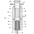
図2に詳しく示すように、蒸発部21は、上端にフランジを有する円筒形状のケース23の中心軸上に給水管15が挿入されて起立しており、この給水管15の周囲は円筒形の断熱材24により覆われている。断熱材24の上端は外周側が低くなるようなテーパが形成されている。さらにこの断熱材24の周囲にコイル状にヒータ26が配置され、断熱材24とケース23との間に加熱媒体27が充填されている。ヒータ26としては、例えば細径のシーズヒータが適当である。このヒータ26には、コネクタ33を介して電源・制御部40が接続されている。また、加熱媒体27としては、熱伝導が良好で、且つ給水管15の上端から水を滴下した時に、その水が浸透しやすいものがよい。その一例としては、アルミニウム粒子等をあげることが出来る。例えばアルミニウム型材の成型や切削による生じるアルミニウム屑等を使用することが出来る。さらに、ケース23の周囲は断熱材28で覆われている。
As shown in detail in FIG. 2, the evaporating
図1に示すように、給水タンク46の開閉自在な栓41に給水ポンプ42が接続され、この給水ポンプ42は分岐管13の一つのポートを介して前記給水管15に接続されている。また、この給水ポンプ42は分岐管13のもう一つのポートを介して逃がしドレンバルブ43に接続され、この逃がしドレンバルブ43は水回収タンク45に接続されている。これらの給水ポンプ42と逃がしドレンバルブ43は、電源・制御部40により動作制御される。
As shown in FIG. 1, a water supply pump 42 is connected to an openable /
図2に詳しく示すように、蒸気過熱部22は、円筒形状のケース29の上下両端のフランジにより、それぞれ前記蒸気導入部18と蒸発部21との間に挿入、接続されたものである。ケース29の内側には、図3に示すような、熱伝導良好なアルミニウム板等により組んだ平面+字形の上下に長い放熱フィン30が挿入され、この放熱フィン30の外周側に細径のシーズヒータ等からなるコイル状のヒータ31が接触または埋め込まれている。図1に示すように、このヒータ31には、コネクタ34を介して電源・制御部40が接続されている。ケース29の外周側は断熱材32で覆われている。
As shown in detail in FIG. 2, the
このような構成からなる蒸気加熱調理器の使用例を図1により説明する。
例えば図1に示すように、セイロ47を煮汁受1の周壁の上に立てて設置し、その中に焼売や肉まん等の食材49或いは茶碗蒸し等の容器50を収納する。その後、取っ手10を持って蓋体4を外容器3に被せる。この状態では図1に示すように、外容器3と蓋体4との間に気密に閉じられた蒸気加熱室11が形成され、セイロ47がこの蒸気加熱室11内に収納されている。
蓋検知センサ17は、蓋体4が外容器3に被せられると、これを検知し、電源・制御部が蒸気発生の動作を行うことを可能とする。
An example of use of a steam heating cooker having such a configuration will be described with reference to FIG.
For example, as shown in FIG. 1, the
The
この状態でまず、ヒータ26、31を発熱し、蒸発部21の加熱媒体27と蒸気過熱部22の放熱フィン30をそれぞれ高温に加熱する。さらに、給水タンク46の栓41を開き、給水ポンプ42を動作させて給水管15に水を送り、この給水管15の上端から加熱媒体27に水を滴下する。給水管15の上端から毎時少量ずつ滴下される水は断熱材24の上端のテーパに沿って高温に加熱された加熱媒体27に滴下される。加熱媒体27の温度が200℃以上と高い場合は、その上に滴下された水は、加熱媒体27の内部に浸透する間もなく瞬時に蒸発して蒸気を発生する。なお、ドレンバルブ43の調整により、余剰の供給水は水回収タンク45に回収される。
In this state, first, the
発生した蒸気は蒸発部21の上に接続されている蒸気過熱部22に上昇し、その中の高温に加熱されている放熱フィン30の間を通過する。この過程で蒸気はさらに加熱され、過熱蒸気となる。ヒータ31に使用されるシーズヒータの最高加熱温度は500℃以上とすることが出来るため、過熱蒸気を300℃程度の高温することは容易である。この蒸気の温度は加熱調理する食材や料理の方法等によって決定するが、蒸し料理の場合は、せいぜい150℃の温度の蒸気で十分である。
The generated steam rises to the
蒸気過熱部22で加熱された蒸気は、蒸気導入部18の蒸気通過孔19を通って蒸気加熱室11の中に入り、セイロ47の中の食材49や容器50に接触、通過し、蒸し加熱による調理が行われる。セイロ47を通って蓋体4の内壁16側に流れた蒸気は、温度が低下し、その内壁16に沿ってセイロ47の周囲を下降する。そして結露し、その露滴が凝集することにより、蓋体4の内壁16に沿って水が下降し、外容器3の水受け部6に集まる。この水受け部6に集まった水は、ドレン部44のドレン配管を通して水回収タンク45に回収される。
The steam heated in the
こうして蒸気により食材49等の加熱調理が済んで時は、給水ポンプ42を停止すると共に、ヒータ26、31への通電を停止し、蒸気の発生を止める。その後しばらく蒸気加熱室11内が落ち着いた後、蓋体4を外容器3から外し、加熱調理した料理をテーブル2の上やテーブル2の上に置いた取り皿に取り出し、テーブル2を囲んで着座した客がその料理を食する。
Thus, when the cooking of the
この間、蓋体4が外容器3から不意に外されると、蓋検知センサ17がそれを検知し、その信号を電源・制御部40に送ってヒータ26、31への通電を停止すると共に、給水ポンプ42を停止し、給水管15への給水を停止する。このため、速やかに蒸気の発生が停止され、火傷等が未然に防止される。
During this time, when the lid 4 is unexpectedly removed from the
図4は、煮汁受1の上に設置したゴトク25の上に鍋51を載せて、この鍋51の中の料理を加熱調理する使用例である。この使用例では、高温の蒸気が必要となるため、蒸発部21で発生した蒸気を蒸気過熱器22でさらに加熱し、300℃程度の温度にして蒸気導入部18の蒸気通過孔19から鍋51の底面及び周壁に接触させる。これにより、鍋51の中の料理を加熱調理する。それ以外の使用方法は図1に前述した実施形態と同じであり、同じ部分は同じ符号で示している。同じ符号の部分の構成は図1に示した使用例と同じである。
FIG. 4 is an example of use in which a
2 テーブル
3 外容器
4 蓋体
5 テーブルの孔
11 蒸気加熱室
17 蓋センサ
18 蒸気導入部
20 蒸発器
21 蒸発器の蒸発部
22 蒸発器の蒸気過熱部
26 ヒータ
27 加熱媒体
31 ヒータ
40 電源・制御器
44 ドレン部
2 Table 3 Outer Container 4 Lid 5
Claims (5)
Priority Applications (1)
| Application Number | Priority Date | Filing Date | Title |
|---|---|---|---|
| JP2003297243A JP2005065819A (en) | 2003-08-21 | 2003-08-21 | Steam cooker |
Applications Claiming Priority (1)
| Application Number | Priority Date | Filing Date | Title |
|---|---|---|---|
| JP2003297243A JP2005065819A (en) | 2003-08-21 | 2003-08-21 | Steam cooker |
Publications (1)
| Publication Number | Publication Date |
|---|---|
| JP2005065819A true JP2005065819A (en) | 2005-03-17 |
Family
ID=34403167
Family Applications (1)
| Application Number | Title | Priority Date | Filing Date |
|---|---|---|---|
| JP2003297243A Pending JP2005065819A (en) | 2003-08-21 | 2003-08-21 | Steam cooker |
Country Status (1)
| Country | Link |
|---|---|
| JP (1) | JP2005065819A (en) |
Cited By (14)
| Publication number | Priority date | Publication date | Assignee | Title |
|---|---|---|---|---|
| JP2006349313A (en) * | 2005-06-20 | 2006-12-28 | Toshiba Corp | Cooking equipment |
| JP2008215767A (en) * | 2007-03-07 | 2008-09-18 | Toshiba Corp | Cooker |
| KR101000803B1 (en) | 2010-01-28 | 2010-12-13 | 오문근 | Cookware using superheated steam |
| KR101077764B1 (en) | 2009-08-19 | 2011-10-27 | 이병순 | A food warmer |
| WO2011136468A3 (en) * | 2010-04-30 | 2012-01-12 | (주)에너지닥터 | Easy-to-use rice cake steaming device |
| KR101137599B1 (en) * | 2009-09-24 | 2012-04-19 | 양승철 | A cubic heating mode cooking uten |
| KR101350161B1 (en) | 2012-06-29 | 2014-01-08 | 곽성호 | Instant steamer for cooking |
| CN103948307A (en) * | 2014-04-04 | 2014-07-30 | 江门佳利华实业有限公司 | Water pot of fuel gas steam box and smoke exhaust system |
| CN104042107A (en) * | 2013-03-13 | 2014-09-17 | 东莞市微电环保科技有限公司 | Energy-saving type electric steaming method and device |
| WO2016079935A1 (en) * | 2014-11-18 | 2016-05-26 | パナソニックIpマネジメント株式会社 | Heat-cooking apparatus |
| JP2016102620A (en) * | 2014-11-28 | 2016-06-02 | 株式会社コメットカトウ | Heating cooker |
| CN108587844A (en) * | 2018-05-18 | 2018-09-28 | 安徽金种子酒业股份有限公司 | A kind of white spirit brewing steaming with pressure and Steam Recovery circulator |
| JP2022169164A (en) * | 2021-04-27 | 2022-11-09 | 東芝ライフスタイル株式会社 | clothing processing equipment |
| US12279712B2 (en) | 2018-11-15 | 2025-04-22 | Koninklijke Philips N.V. | Steam cooking apparatus and method |
-
2003
- 2003-08-21 JP JP2003297243A patent/JP2005065819A/en active Pending
Cited By (19)
| Publication number | Priority date | Publication date | Assignee | Title |
|---|---|---|---|---|
| JP2006349313A (en) * | 2005-06-20 | 2006-12-28 | Toshiba Corp | Cooking equipment |
| JP2008215767A (en) * | 2007-03-07 | 2008-09-18 | Toshiba Corp | Cooker |
| KR101077764B1 (en) | 2009-08-19 | 2011-10-27 | 이병순 | A food warmer |
| KR101137599B1 (en) * | 2009-09-24 | 2012-04-19 | 양승철 | A cubic heating mode cooking uten |
| KR101000803B1 (en) | 2010-01-28 | 2010-12-13 | 오문근 | Cookware using superheated steam |
| WO2011136468A3 (en) * | 2010-04-30 | 2012-01-12 | (주)에너지닥터 | Easy-to-use rice cake steaming device |
| KR101129091B1 (en) | 2010-04-30 | 2012-03-23 | 주식회사 에너지닥터 | A simple apparatus for rice cake |
| KR101350161B1 (en) | 2012-06-29 | 2014-01-08 | 곽성호 | Instant steamer for cooking |
| CN104042107A (en) * | 2013-03-13 | 2014-09-17 | 东莞市微电环保科技有限公司 | Energy-saving type electric steaming method and device |
| CN103948307A (en) * | 2014-04-04 | 2014-07-30 | 江门佳利华实业有限公司 | Water pot of fuel gas steam box and smoke exhaust system |
| CN103948307B (en) * | 2014-04-04 | 2017-01-25 | 江门佳利华实业有限公司 | Smoke exhaust system of water pot of fuel gas steam box |
| WO2016079935A1 (en) * | 2014-11-18 | 2016-05-26 | パナソニックIpマネジメント株式会社 | Heat-cooking apparatus |
| JP2016099010A (en) * | 2014-11-18 | 2016-05-30 | パナソニックIpマネジメント株式会社 | Cooker |
| CN107003004A (en) * | 2014-11-18 | 2017-08-01 | 松下知识产权经营株式会社 | heating cooker |
| JP2016102620A (en) * | 2014-11-28 | 2016-06-02 | 株式会社コメットカトウ | Heating cooker |
| CN108587844A (en) * | 2018-05-18 | 2018-09-28 | 安徽金种子酒业股份有限公司 | A kind of white spirit brewing steaming with pressure and Steam Recovery circulator |
| US12279712B2 (en) | 2018-11-15 | 2025-04-22 | Koninklijke Philips N.V. | Steam cooking apparatus and method |
| JP2022169164A (en) * | 2021-04-27 | 2022-11-09 | 東芝ライフスタイル株式会社 | clothing processing equipment |
| JP7663406B2 (en) | 2021-04-27 | 2025-04-16 | 東芝ライフスタイル株式会社 | Clothes Processing Equipment |
Similar Documents
| Publication | Publication Date | Title |
|---|---|---|
| US4655192A (en) | Cooking apparatus using steam injection at atmospheric pressure | |
| US6267046B1 (en) | Convection steamer | |
| EP3884820B1 (en) | Air fryer with steaming function and method for controlling air fryer with steaming function | |
| US5631033A (en) | Method of cooking food with steam | |
| JP2005065819A (en) | Steam cooker | |
| US6539839B1 (en) | Uniform temperature cooking surface | |
| US20110056957A1 (en) | Combination Multiple Vessel Cookware | |
| US10463186B2 (en) | Device for cooking and heating and/or reviving of portions of fresh and/or frozen pre-cooked pasta and other food preparations | |
| EP2606776B1 (en) | Pressurized steam cooker | |
| US6911626B2 (en) | Overheated steam oven | |
| EP1541025A1 (en) | Overheated steam oven | |
| US11297857B2 (en) | Apparatus and process for rapidly cooking food | |
| US6310325B1 (en) | Steamer oven with controlled condensing of steam | |
| US3431835A (en) | Cooking food under pressure | |
| JP4263130B2 (en) | Steam generator | |
| JP2005065847A (en) | Steam supplier for steam cooker | |
| US7538300B1 (en) | Polygonal cooking apparatus with a pressurizable condensate jacket | |
| US6668707B2 (en) | Fuel-efficient steam cooking device | |
| CN109527980A (en) | Steaming and baking combined machine | |
| JP2887309B2 (en) | Cooking device | |
| KR101019413B1 (en) | Cooking device using steam pressure with seating means | |
| CN215738370U (en) | A cooking utensil with both steaming and roasting functions | |
| CN108784313B (en) | Cooking appliance and control method thereof | |
| JP2003250505A (en) | Method for cooking frozen food and defrosting machine for the frozen food | |
| JP4375667B2 (en) | Drain vapor recovery device and diffuser for drain vapor recovery |
Legal Events
| Date | Code | Title | Description |
|---|---|---|---|
| A977 | Report on retrieval |
Effective date: 20050624 Free format text: JAPANESE INTERMEDIATE CODE: A971007 |
|
| A131 | Notification of reasons for refusal |
Free format text: JAPANESE INTERMEDIATE CODE: A131 Effective date: 20050705 |
|
| A521 | Written amendment |
Free format text: JAPANESE INTERMEDIATE CODE: A523 Effective date: 20050817 |
|
| A02 | Decision of refusal |
Effective date: 20051101 Free format text: JAPANESE INTERMEDIATE CODE: A02 |