JP2005038579A - Magnetic recording medium - Google Patents
Magnetic recording medium Download PDFInfo
- Publication number
- JP2005038579A JP2005038579A JP2004160510A JP2004160510A JP2005038579A JP 2005038579 A JP2005038579 A JP 2005038579A JP 2004160510 A JP2004160510 A JP 2004160510A JP 2004160510 A JP2004160510 A JP 2004160510A JP 2005038579 A JP2005038579 A JP 2005038579A
- Authority
- JP
- Japan
- Prior art keywords
- magnetic
- recording medium
- servo
- magnetic layer
- layer
- Prior art date
- Legal status (The legal status is an assumption and is not a legal conclusion. Google has not performed a legal analysis and makes no representation as to the accuracy of the status listed.)
- Pending
Links
- 230000005291 magnetic effect Effects 0.000 title claims abstract description 254
- 230000005415 magnetization Effects 0.000 claims abstract description 53
- 239000000843 powder Substances 0.000 claims description 57
- 239000006247 magnetic powder Substances 0.000 claims description 35
- 239000011230 binding agent Substances 0.000 claims description 19
- 229910052751 metal Inorganic materials 0.000 claims description 19
- 239000002184 metal Substances 0.000 claims description 19
- 229910000859 α-Fe Inorganic materials 0.000 claims description 18
- 230000005294 ferromagnetic effect Effects 0.000 claims description 15
- 238000009826 distribution Methods 0.000 claims description 8
- 239000010410 layer Substances 0.000 description 168
- 238000000034 method Methods 0.000 description 53
- 238000000576 coating method Methods 0.000 description 51
- 239000011248 coating agent Substances 0.000 description 47
- 239000002609 medium Substances 0.000 description 47
- 239000006229 carbon black Substances 0.000 description 34
- 235000019241 carbon black Nutrition 0.000 description 34
- 239000002245 particle Substances 0.000 description 29
- 230000000052 comparative effect Effects 0.000 description 28
- 239000002585 base Substances 0.000 description 23
- ZWEHNKRNPOVVGH-UHFFFAOYSA-N 2-Butanone Chemical compound CCC(C)=O ZWEHNKRNPOVVGH-UHFFFAOYSA-N 0.000 description 21
- 239000007788 liquid Substances 0.000 description 18
- 230000001105 regulatory effect Effects 0.000 description 18
- 230000008569 process Effects 0.000 description 15
- 230000008859 change Effects 0.000 description 13
- YXFVVABEGXRONW-UHFFFAOYSA-N Toluene Chemical compound CC1=CC=CC=C1 YXFVVABEGXRONW-UHFFFAOYSA-N 0.000 description 12
- -1 etc. Substances 0.000 description 12
- 229920005989 resin Polymers 0.000 description 11
- 239000011347 resin Substances 0.000 description 11
- JHIVVAPYMSGYDF-UHFFFAOYSA-N cyclohexanone Chemical compound O=C1CCCCC1 JHIVVAPYMSGYDF-UHFFFAOYSA-N 0.000 description 10
- 230000002457 bidirectional effect Effects 0.000 description 8
- 239000000203 mixture Substances 0.000 description 8
- 238000004438 BET method Methods 0.000 description 7
- 239000000314 lubricant Substances 0.000 description 7
- 229920005749 polyurethane resin Polymers 0.000 description 7
- 238000010586 diagram Methods 0.000 description 6
- 239000002270 dispersing agent Substances 0.000 description 6
- 238000001035 drying Methods 0.000 description 6
- 238000004519 manufacturing process Methods 0.000 description 6
- 238000002360 preparation method Methods 0.000 description 6
- 235000021355 Stearic acid Nutrition 0.000 description 5
- 239000006185 dispersion Substances 0.000 description 5
- 238000005259 measurement Methods 0.000 description 5
- QIQXTHQIDYTFRH-UHFFFAOYSA-N octadecanoic acid Chemical compound CCCCCCCCCCCCCCCCCC(O)=O QIQXTHQIDYTFRH-UHFFFAOYSA-N 0.000 description 5
- OQCDKBAXFALNLD-UHFFFAOYSA-N octadecanoic acid Natural products CCCCCCCC(C)CCCCCCCCC(O)=O OQCDKBAXFALNLD-UHFFFAOYSA-N 0.000 description 5
- 239000004417 polycarbonate Substances 0.000 description 5
- 229920002635 polyurethane Polymers 0.000 description 5
- 239000004814 polyurethane Substances 0.000 description 5
- 229910052761 rare earth metal Inorganic materials 0.000 description 5
- 150000002910 rare earth metals Chemical class 0.000 description 5
- 239000008117 stearic acid Substances 0.000 description 5
- 230000003746 surface roughness Effects 0.000 description 5
- OKTJSMMVPCPJKN-UHFFFAOYSA-N Carbon Chemical compound [C] OKTJSMMVPCPJKN-UHFFFAOYSA-N 0.000 description 4
- TZCXTZWJZNENPQ-UHFFFAOYSA-L barium sulfate Chemical compound [Ba+2].[O-]S([O-])(=O)=O TZCXTZWJZNENPQ-UHFFFAOYSA-L 0.000 description 4
- 229920001577 copolymer Polymers 0.000 description 4
- 235000014113 dietary fatty acids Nutrition 0.000 description 4
- 239000000194 fatty acid Substances 0.000 description 4
- 229930195729 fatty acid Natural products 0.000 description 4
- XEEYBQQBJWHFJM-UHFFFAOYSA-N iron Substances [Fe] XEEYBQQBJWHFJM-UHFFFAOYSA-N 0.000 description 4
- 239000000696 magnetic material Substances 0.000 description 4
- 239000006249 magnetic particle Substances 0.000 description 4
- 230000005389 magnetism Effects 0.000 description 4
- 238000002156 mixing Methods 0.000 description 4
- 229920000728 polyester Polymers 0.000 description 4
- QMMJWQMCMRUYTG-UHFFFAOYSA-N 1,2,4,5-tetrachloro-3-(trifluoromethyl)benzene Chemical compound FC(F)(F)C1=C(Cl)C(Cl)=CC(Cl)=C1Cl QMMJWQMCMRUYTG-UHFFFAOYSA-N 0.000 description 3
- UPMLOUAZCHDJJD-UHFFFAOYSA-N 4,4'-Diphenylmethane Diisocyanate Chemical compound C1=CC(N=C=O)=CC=C1CC1=CC=C(N=C=O)C=C1 UPMLOUAZCHDJJD-UHFFFAOYSA-N 0.000 description 3
- PNEYBMLMFCGWSK-UHFFFAOYSA-N Alumina Chemical compound [O-2].[O-2].[O-2].[Al+3].[Al+3] PNEYBMLMFCGWSK-UHFFFAOYSA-N 0.000 description 3
- 239000000020 Nitrocellulose Substances 0.000 description 3
- 230000002776 aggregation Effects 0.000 description 3
- 239000011324 bead Substances 0.000 description 3
- 125000004432 carbon atom Chemical group C* 0.000 description 3
- 238000006243 chemical reaction Methods 0.000 description 3
- 238000007765 extrusion coating Methods 0.000 description 3
- 150000004665 fatty acids Chemical class 0.000 description 3
- 230000004907 flux Effects 0.000 description 3
- 230000001965 increasing effect Effects 0.000 description 3
- 238000004898 kneading Methods 0.000 description 3
- SLCVBVWXLSEKPL-UHFFFAOYSA-N neopentyl glycol Chemical compound OCC(C)(C)CO SLCVBVWXLSEKPL-UHFFFAOYSA-N 0.000 description 3
- 229920001220 nitrocellulos Polymers 0.000 description 3
- 229920001228 polyisocyanate Polymers 0.000 description 3
- 239000005056 polyisocyanate Substances 0.000 description 3
- 238000006116 polymerization reaction Methods 0.000 description 3
- 229920005862 polyol Polymers 0.000 description 3
- 239000011164 primary particle Substances 0.000 description 3
- 239000004576 sand Substances 0.000 description 3
- ZQPPMHVWECSIRJ-UHFFFAOYSA-N Oleic acid Natural products CCCCCCCCC=CCCCCCCCC(O)=O ZQPPMHVWECSIRJ-UHFFFAOYSA-N 0.000 description 2
- 239000004952 Polyamide Substances 0.000 description 2
- 239000004962 Polyamide-imide Substances 0.000 description 2
- 239000004642 Polyimide Substances 0.000 description 2
- 229910010413 TiO 2 Inorganic materials 0.000 description 2
- GWEVSGVZZGPLCZ-UHFFFAOYSA-N Titan oxide Chemical compound O=[Ti]=O GWEVSGVZZGPLCZ-UHFFFAOYSA-N 0.000 description 2
- BZHJMEDXRYGGRV-UHFFFAOYSA-N Vinyl chloride Chemical compound ClC=C BZHJMEDXRYGGRV-UHFFFAOYSA-N 0.000 description 2
- MCMNRKCIXSYSNV-UHFFFAOYSA-N Zirconium dioxide Chemical compound O=[Zr]=O MCMNRKCIXSYSNV-UHFFFAOYSA-N 0.000 description 2
- 238000010521 absorption reaction Methods 0.000 description 2
- 238000004220 aggregation Methods 0.000 description 2
- 229910052783 alkali metal Inorganic materials 0.000 description 2
- 150000001340 alkali metals Chemical class 0.000 description 2
- 125000000217 alkyl group Chemical group 0.000 description 2
- WYTGDNHDOZPMIW-RCBQFDQVSA-N alstonine Natural products C1=CC2=C3C=CC=CC3=NC2=C2N1C[C@H]1[C@H](C)OC=C(C(=O)OC)[C@H]1C2 WYTGDNHDOZPMIW-RCBQFDQVSA-N 0.000 description 2
- 239000002216 antistatic agent Substances 0.000 description 2
- 239000004760 aramid Substances 0.000 description 2
- 229920003235 aromatic polyamide Polymers 0.000 description 2
- 238000003490 calendering Methods 0.000 description 2
- HGAZMNJKRQFZKS-UHFFFAOYSA-N chloroethene;ethenyl acetate Chemical compound ClC=C.CC(=O)OC=C HGAZMNJKRQFZKS-UHFFFAOYSA-N 0.000 description 2
- 239000011362 coarse particle Substances 0.000 description 2
- 150000001875 compounds Chemical class 0.000 description 2
- 230000001276 controlling effect Effects 0.000 description 2
- GHVNFZFCNZKVNT-UHFFFAOYSA-N decanoic acid Chemical compound CCCCCCCCCC(O)=O GHVNFZFCNZKVNT-UHFFFAOYSA-N 0.000 description 2
- 239000002612 dispersion medium Substances 0.000 description 2
- UKMSUNONTOPOIO-UHFFFAOYSA-N docosanoic acid Chemical compound CCCCCCCCCCCCCCCCCCCCCC(O)=O UKMSUNONTOPOIO-UHFFFAOYSA-N 0.000 description 2
- POULHZVOKOAJMA-UHFFFAOYSA-N dodecanoic acid Chemical compound CCCCCCCCCCCC(O)=O POULHZVOKOAJMA-UHFFFAOYSA-N 0.000 description 2
- 230000000694 effects Effects 0.000 description 2
- ZQPPMHVWECSIRJ-MDZDMXLPSA-N elaidic acid Chemical compound CCCCCCCC\C=C\CCCCCCCC(O)=O ZQPPMHVWECSIRJ-MDZDMXLPSA-N 0.000 description 2
- 238000011156 evaluation Methods 0.000 description 2
- 230000002349 favourable effect Effects 0.000 description 2
- 239000000945 filler Substances 0.000 description 2
- 238000001914 filtration Methods 0.000 description 2
- 239000010419 fine particle Substances 0.000 description 2
- RBTKNAXYKSUFRK-UHFFFAOYSA-N heliogen blue Chemical compound [Cu].[N-]1C2=C(C=CC=C3)C3=C1N=C([N-]1)C3=CC=CC=C3C1=NC([N-]1)=C(C=CC=C3)C3=C1N=C([N-]1)C3=CC=CC=C3C1=N2 RBTKNAXYKSUFRK-UHFFFAOYSA-N 0.000 description 2
- IPCSVZSSVZVIGE-UHFFFAOYSA-N hexadecanoic acid Chemical compound CCCCCCCCCCCCCCCC(O)=O IPCSVZSSVZVIGE-UHFFFAOYSA-N 0.000 description 2
- 238000000024 high-resolution transmission electron micrograph Methods 0.000 description 2
- 230000001939 inductive effect Effects 0.000 description 2
- 239000003112 inhibitor Substances 0.000 description 2
- QXJSBBXBKPUZAA-UHFFFAOYSA-N isooleic acid Natural products CCCCCCCC=CCCCCCCCCC(O)=O QXJSBBXBKPUZAA-UHFFFAOYSA-N 0.000 description 2
- 239000000463 material Substances 0.000 description 2
- 239000012046 mixed solvent Substances 0.000 description 2
- WWZKQHOCKIZLMA-UHFFFAOYSA-N octanoic acid Chemical compound CCCCCCCC(O)=O WWZKQHOCKIZLMA-UHFFFAOYSA-N 0.000 description 2
- 229920003023 plastic Polymers 0.000 description 2
- 239000004033 plastic Substances 0.000 description 2
- 229920002647 polyamide Polymers 0.000 description 2
- 229920002312 polyamide-imide Polymers 0.000 description 2
- 229920000139 polyethylene terephthalate Polymers 0.000 description 2
- 239000005020 polyethylene terephthalate Substances 0.000 description 2
- 229920001721 polyimide Polymers 0.000 description 2
- 239000011148 porous material Substances 0.000 description 2
- 230000010349 pulsation Effects 0.000 description 2
- 239000002994 raw material Substances 0.000 description 2
- 230000009467 reduction Effects 0.000 description 2
- 238000005245 sintering Methods 0.000 description 2
- 238000001228 spectrum Methods 0.000 description 2
- 230000009974 thixotropic effect Effects 0.000 description 2
- 238000012546 transfer Methods 0.000 description 2
- 238000002834 transmittance Methods 0.000 description 2
- 229910052727 yttrium Inorganic materials 0.000 description 2
- WRIDQFICGBMAFQ-UHFFFAOYSA-N (E)-8-Octadecenoic acid Natural products CCCCCCCCCC=CCCCCCCC(O)=O WRIDQFICGBMAFQ-UHFFFAOYSA-N 0.000 description 1
- IIZPXYDJLKNOIY-JXPKJXOSSA-N 1-palmitoyl-2-arachidonoyl-sn-glycero-3-phosphocholine Chemical compound CCCCCCCCCCCCCCCC(=O)OC[C@H](COP([O-])(=O)OCC[N+](C)(C)C)OC(=O)CCC\C=C/C\C=C/C\C=C/C\C=C/CCCCC IIZPXYDJLKNOIY-JXPKJXOSSA-N 0.000 description 1
- LGEZTMRIZWCDLW-UHFFFAOYSA-N 14-methylpentadecyl octadecanoate Chemical compound CCCCCCCCCCCCCCCCCC(=O)OCCCCCCCCCCCCCC(C)C LGEZTMRIZWCDLW-UHFFFAOYSA-N 0.000 description 1
- NHUXFMNHQIITCP-UHFFFAOYSA-N 2-butoxyethyl octadecanoate Chemical compound CCCCCCCCCCCCCCCCCC(=O)OCCOCCCC NHUXFMNHQIITCP-UHFFFAOYSA-N 0.000 description 1
- LQJBNNIYVWPHFW-UHFFFAOYSA-N 20:1omega9c fatty acid Natural products CCCCCCCCCCC=CCCCCCCCC(O)=O LQJBNNIYVWPHFW-UHFFFAOYSA-N 0.000 description 1
- QSBYPNXLFMSGKH-UHFFFAOYSA-N 9-Heptadecensaeure Natural products CCCCCCCC=CCCCCCCCC(O)=O QSBYPNXLFMSGKH-UHFFFAOYSA-N 0.000 description 1
- 239000004925 Acrylic resin Substances 0.000 description 1
- 229920000178 Acrylic resin Polymers 0.000 description 1
- 229910018072 Al 2 O 3 Inorganic materials 0.000 description 1
- 235000021357 Behenic acid Nutrition 0.000 description 1
- 239000005632 Capric acid (CAS 334-48-5) Substances 0.000 description 1
- 239000005635 Caprylic acid (CAS 124-07-2) Substances 0.000 description 1
- 229920002284 Cellulose triacetate Polymers 0.000 description 1
- 239000004593 Epoxy Substances 0.000 description 1
- PXGOKWXKJXAPGV-UHFFFAOYSA-N Fluorine Chemical compound FF PXGOKWXKJXAPGV-UHFFFAOYSA-N 0.000 description 1
- 239000005639 Lauric acid Substances 0.000 description 1
- 239000005642 Oleic acid Substances 0.000 description 1
- 229910019142 PO4 Inorganic materials 0.000 description 1
- 235000021314 Palmitic acid Nutrition 0.000 description 1
- 229910000831 Steel Inorganic materials 0.000 description 1
- NNLVGZFZQQXQNW-ADJNRHBOSA-N [(2r,3r,4s,5r,6s)-4,5-diacetyloxy-3-[(2s,3r,4s,5r,6r)-3,4,5-triacetyloxy-6-(acetyloxymethyl)oxan-2-yl]oxy-6-[(2r,3r,4s,5r,6s)-4,5,6-triacetyloxy-2-(acetyloxymethyl)oxan-3-yl]oxyoxan-2-yl]methyl acetate Chemical compound O([C@@H]1O[C@@H]([C@H]([C@H](OC(C)=O)[C@H]1OC(C)=O)O[C@H]1[C@@H]([C@@H](OC(C)=O)[C@H](OC(C)=O)[C@@H](COC(C)=O)O1)OC(C)=O)COC(=O)C)[C@@H]1[C@@H](COC(C)=O)O[C@@H](OC(C)=O)[C@H](OC(C)=O)[C@H]1OC(C)=O NNLVGZFZQQXQNW-ADJNRHBOSA-N 0.000 description 1
- 239000002253 acid Substances 0.000 description 1
- 239000012790 adhesive layer Substances 0.000 description 1
- 238000005054 agglomeration Methods 0.000 description 1
- 229910052784 alkaline earth metal Inorganic materials 0.000 description 1
- 150000001342 alkaline earth metals Chemical class 0.000 description 1
- 150000001336 alkenes Chemical class 0.000 description 1
- 125000003342 alkenyl group Chemical group 0.000 description 1
- 229910045601 alloy Inorganic materials 0.000 description 1
- 239000000956 alloy Substances 0.000 description 1
- JZQOJFLIJNRDHK-CMDGGOBGSA-N alpha-irone Chemical compound CC1CC=C(C)C(\C=C\C(C)=O)C1(C)C JZQOJFLIJNRDHK-CMDGGOBGSA-N 0.000 description 1
- DTOSIQBPPRVQHS-PDBXOOCHSA-N alpha-linolenic acid Chemical compound CC\C=C/C\C=C/C\C=C/CCCCCCCC(O)=O DTOSIQBPPRVQHS-PDBXOOCHSA-N 0.000 description 1
- 235000020661 alpha-linolenic acid Nutrition 0.000 description 1
- 229940116226 behenic acid Drugs 0.000 description 1
- 230000005540 biological transmission Effects 0.000 description 1
- 229910052799 carbon Inorganic materials 0.000 description 1
- 239000011247 coating layer Substances 0.000 description 1
- 238000013329 compounding Methods 0.000 description 1
- SVOAENZIOKPANY-CVBJKYQLSA-L copper;(z)-octadec-9-enoate Chemical compound [Cu+2].CCCCCCCC\C=C/CCCCCCCC([O-])=O.CCCCCCCC\C=C/CCCCCCCC([O-])=O SVOAENZIOKPANY-CVBJKYQLSA-L 0.000 description 1
- 238000003851 corona treatment Methods 0.000 description 1
- 238000005520 cutting process Methods 0.000 description 1
- 230000005347 demagnetization Effects 0.000 description 1
- 229910003460 diamond Inorganic materials 0.000 description 1
- 239000010432 diamond Substances 0.000 description 1
- 239000000428 dust Substances 0.000 description 1
- 229920001971 elastomer Polymers 0.000 description 1
- 239000003822 epoxy resin Substances 0.000 description 1
- 239000011737 fluorine Substances 0.000 description 1
- 229910052731 fluorine Inorganic materials 0.000 description 1
- 230000009477 glass transition Effects 0.000 description 1
- 229910002804 graphite Inorganic materials 0.000 description 1
- 239000010439 graphite Substances 0.000 description 1
- 230000005484 gravity Effects 0.000 description 1
- 238000007756 gravure coating Methods 0.000 description 1
- 238000010438 heat treatment Methods 0.000 description 1
- 125000004435 hydrogen atom Chemical group [H]* 0.000 description 1
- 238000010191 image analysis Methods 0.000 description 1
- 239000000787 lecithin Substances 0.000 description 1
- 229940067606 lecithin Drugs 0.000 description 1
- 235000010445 lecithin Nutrition 0.000 description 1
- 229960004488 linolenic acid Drugs 0.000 description 1
- KQQKGWQCNNTQJW-UHFFFAOYSA-N linolenic acid Natural products CC=CCCC=CCC=CCCCCCCCC(O)=O KQQKGWQCNNTQJW-UHFFFAOYSA-N 0.000 description 1
- 230000014759 maintenance of location Effects 0.000 description 1
- 229910052748 manganese Inorganic materials 0.000 description 1
- 229910044991 metal oxide Inorganic materials 0.000 description 1
- 150000004706 metal oxides Chemical class 0.000 description 1
- 238000012986 modification Methods 0.000 description 1
- 230000004048 modification Effects 0.000 description 1
- WQEPLUUGTLDZJY-UHFFFAOYSA-N n-Pentadecanoic acid Natural products CCCCCCCCCCCCCCC(O)=O WQEPLUUGTLDZJY-UHFFFAOYSA-N 0.000 description 1
- 229910052758 niobium Inorganic materials 0.000 description 1
- 229960002446 octanoic acid Drugs 0.000 description 1
- JRZJOMJEPLMPRA-UHFFFAOYSA-N olefin Natural products CCCCCCCC=C JRZJOMJEPLMPRA-UHFFFAOYSA-N 0.000 description 1
- 235000021313 oleic acid Nutrition 0.000 description 1
- 239000003960 organic solvent Substances 0.000 description 1
- 230000010363 phase shift Effects 0.000 description 1
- 229920006287 phenoxy resin Polymers 0.000 description 1
- 239000013034 phenoxy resin Substances 0.000 description 1
- 239000010452 phosphate Substances 0.000 description 1
- 230000000704 physical effect Effects 0.000 description 1
- 238000009832 plasma treatment Methods 0.000 description 1
- 229920000233 poly(alkylene oxides) Polymers 0.000 description 1
- 229920003207 poly(ethylene-2,6-naphthalate) Polymers 0.000 description 1
- 229920002492 poly(sulfone) Polymers 0.000 description 1
- 229920000515 polycarbonate Polymers 0.000 description 1
- 229920000647 polyepoxide Polymers 0.000 description 1
- 229920001225 polyester resin Polymers 0.000 description 1
- 239000004645 polyester resin Substances 0.000 description 1
- 239000011112 polyethylene naphthalate Substances 0.000 description 1
- 229920000098 polyolefin Polymers 0.000 description 1
- 238000001556 precipitation Methods 0.000 description 1
- 239000011241 protective layer Substances 0.000 description 1
- 150000003242 quaternary ammonium salts Chemical class 0.000 description 1
- 230000003252 repetitive effect Effects 0.000 description 1
- 239000013557 residual solvent Substances 0.000 description 1
- 230000004044 response Effects 0.000 description 1
- 239000005060 rubber Substances 0.000 description 1
- 239000000344 soap Substances 0.000 description 1
- 239000007787 solid Substances 0.000 description 1
- 239000002904 solvent Substances 0.000 description 1
- 239000010935 stainless steel Substances 0.000 description 1
- 229910001220 stainless steel Inorganic materials 0.000 description 1
- 239000010959 steel Substances 0.000 description 1
- 238000003860 storage Methods 0.000 description 1
- 239000000126 substance Substances 0.000 description 1
- 238000006467 substitution reaction Methods 0.000 description 1
- 238000004381 surface treatment Methods 0.000 description 1
- TUNFSRHWOTWDNC-HKGQFRNVSA-N tetradecanoic acid Chemical compound CCCCCCCCCCCCC[14C](O)=O TUNFSRHWOTWDNC-HKGQFRNVSA-N 0.000 description 1
- 239000006234 thermal black Substances 0.000 description 1
- 229920005992 thermoplastic resin Polymers 0.000 description 1
- 229920001187 thermosetting polymer Polymers 0.000 description 1
- 239000011800 void material Substances 0.000 description 1
- 239000011787 zinc oxide Substances 0.000 description 1
Images


Landscapes
- Magnetic Record Carriers (AREA)
Abstract
Description
本発明は、磁気記録媒体に関する。 The present invention relates to a magnetic recording medium.
近年、磁気記録媒体は、高密度記録化が進んでおり、コンピュータのバックアップ用では100ギガバイト程度の記憶容量を有するものがある。例えば、磁気テープの場合は、幅方向に数百本のデータトラックを形成し、高密度記録化を可能としている。それに伴い、データトラックの幅は非常に狭くなっており、隣接するデータトラック間も非常に狭くなっている。そのため、予め磁気テープにサーボ信号を書き込んでおき、磁気ヘッドでこのサーボ信号を読み取りつつ、磁気ヘッドの位置(磁気テープの幅方向の位置)をサーボ制御することによって、磁気ヘッドの記録・再生素子をデータトラックにトレースさせている(特許文献1参照)。 In recent years, high-density recording has progressed in magnetic recording media, and there is a recording medium having a storage capacity of about 100 gigabytes for computer backup. For example, in the case of a magnetic tape, several hundred data tracks are formed in the width direction to enable high density recording. Along with this, the width of the data track is very narrow, and the space between adjacent data tracks is also very narrow. Therefore, a servo signal is written in advance on the magnetic tape, and the servo signal is read by the magnetic head and the position of the magnetic head (position in the width direction of the magnetic tape) is servo controlled. Are traced on the data track (see Patent Document 1).
このサーボ信号によって磁気ヘッドの位置制御を行うシステムとして、読み取ったパルス信号の出力バランスにより位置制御を行う振幅変調方式や、読み取ったパルス信号のタイミングにより位置制御を行うTBS(Timing Based Servo)方式等がある。
TBS方式におけるサーボ信号を磁気テープ上に記録するシステムにおいては、例えば図3に示すように、テープ搬送系でテープを搬送しながら非平行なパターンのサーボ信号SPをサーボ記録ヘッド(図示せず)によって記録している(図3)。そして、非平行なサーボ信号パターンSPは、磁化されていない磁気テープ上のサーボバンドに、一方向に磁化するように記録電流を付与することで記録されていた。
つまり、図3(b)に示すように、従来のTBS方式ではサーボ信号読取素子(MR素子)の飽和現象を回避するために、磁化されていないサーボバンドSB上に、図3(a)に示すようなゼロ電流とプラスパルス電流とからなる記録パルス電流PCを流して形成していた。
As a system for controlling the position of the magnetic head by this servo signal, an amplitude modulation method for performing position control by the output balance of the read pulse signal, a TBS (Timing Based Servo) method for performing position control by the timing of the read pulse signal, etc. There is.
In a system for recording servo signals on a magnetic tape in the TBS system, for example, as shown in FIG. 3, a servo recording head (not shown) generates a servo signal SP having a non-parallel pattern while transporting the tape in a tape transport system. (FIG. 3). The non-parallel servo signal pattern SP was recorded by applying a recording current so as to be magnetized in one direction to a servo band on a non-magnetized magnetic tape.
That is, as shown in FIG. 3B, in order to avoid the saturation phenomenon of the servo signal reading element (MR element) in the conventional TBS method, the servo band SB which is not magnetized is shown in FIG. The recording pulse current PC composed of a zero current and a plus pulse current as shown in FIG.
このような記録パルス電流PCを用いると、磁気テープMTは、記録パルス電流PCのゼロ電流のときにはサーボパターンSP以外の領域が磁化されず、記録パルス電流PCのプラスパルス電流が流れたときにはサーボパターンSPが一方向に磁化され、結果としてサーボ信号SSが書き込まれる。なお、サーボ信号SSを書き込むための磁気ヘッド(図示せず)のヘッドギャップが、磁気テープMTの走行方向に対して所定の角度を有する非平行なハ字形状を有しているため、図3(a)に示すプラスパルス電流PPaに対し、図3(b)に示すサーボパターンSPaが磁化され、更に、プラスパルス電流PPbに対し、サーボパターンSPbが磁化される。 When such a recording pulse current PC is used, the magnetic tape MT is not magnetized in the area other than the servo pattern SP when the recording pulse current PC is zero current, and the servo pattern when the plus pulse current of the recording pulse current PC flows. The SP is magnetized in one direction, and as a result, the servo signal SS is written. Note that the head gap of the magnetic head (not shown) for writing the servo signal SS has a non-parallel C-shape having a predetermined angle with respect to the traveling direction of the magnetic tape MT. The servo pattern SPa shown in FIG. 3B is magnetized with respect to the plus pulse current PPa shown in (a), and further, the servo pattern SPb is magnetized with respect to the plus pulse current PPb.
一方、磁気テープ記録再生装置では、サーボ信号読取素子によってサーボ信号SSの磁界の変化を電気抵抗の変化で検出し、読取信号として微分波形(電圧値)で出力している。そのため、サーボ信号読取素子の電気抵抗の変化が大きくなるほど、サーボ信号SSの読取信号のピーク電圧値が大きくなり、読取信号のSN比が向上する。したがって、サーボ信号SS自体の磁界の変化が大きい場合やサーボ信号読取素子の幅が広いために読み取る領域が大きい場合、図3(c)に示すように、サーボ信号SSの読取信号RSLのピーク電圧値は大きくなる。 On the other hand, in the magnetic tape recording / reproducing apparatus, a change in the magnetic field of the servo signal SS is detected by a change in electric resistance by a servo signal reading element, and is output as a read signal as a differential waveform (voltage value). Therefore, as the change in the electric resistance of the servo signal reading element increases, the peak voltage value of the read signal of the servo signal SS increases, and the SN ratio of the read signal improves. Therefore, when the change in the magnetic field of the servo signal SS itself is large, or when the reading area is large due to the wide width of the servo signal reading element, the peak voltage of the read signal RSL of the servo signal SS as shown in FIG. The value gets bigger.
ところが、今後、磁気記録媒体は、カートリッジ1巻当りの記録容量が数十テラバイト程度まで高密度記録化が進むことが予測される。
それに伴い、磁気テープの場合では、データトラック数が増え、データトラックの幅および隣接するデータトラック間は一層狭くなるとともに、磁気テープ自体も薄層化する。これにより、サーボ信号を読み取るときに検出できる磁気の量は減少し、サーボ信号読取素子で検出できるサーボ信号SSの磁化量の変化も小さくなる。したがって、図3(d)に示すように、サーボ信号SSの読取信号RSSのピーク電圧値は小さくなり、読取信号RSSのSN比が劣化する。その結果、磁気テープ記録再生装置において、サーボ信号SSを正確に読み取ることができなくなり、高精度な磁気ヘッドの位置制御を行えなくなる。
However, in the future, it is predicted that the recording density of magnetic recording media will increase to a recording capacity of several tens of terabytes per cartridge.
Accordingly, in the case of a magnetic tape, the number of data tracks increases, the width of the data track and the space between adjacent data tracks become narrower, and the magnetic tape itself becomes thinner. As a result, the amount of magnetism that can be detected when reading the servo signal is reduced, and the change in the magnetization amount of the servo signal SS that can be detected by the servo signal reading element is also reduced. Therefore, as shown in FIG. 3D, the peak voltage value of the read signal RSS of the servo signal SS becomes small, and the SN ratio of the read signal RSS deteriorates. As a result, in the magnetic tape recording / reproducing apparatus, the servo signal SS cannot be read accurately, and the position control of the magnetic head with high accuracy cannot be performed.
そこで、本発明の課題は、高密度記録に適する薄い磁性層を有しながら、サーボ信号の読取信号のSN比(以下サーボ信号のSN比とする)を向上させ、データ信号のSN比が良好な磁気記録媒体を提供することにある。 Accordingly, an object of the present invention is to improve the SN ratio of the read signal of the servo signal (hereinafter referred to as the SN ratio of the servo signal) while having a thin magnetic layer suitable for high-density recording, and the SN ratio of the data signal is good. Is to provide a simple magnetic recording medium.
本発明の課題は、以下の手段により解決することができる。
1)支持体上に磁性粉末を含む磁性層を設けた磁気記録媒体であって、
前記磁性層は、磁気ヘッドのトラッキング制御をするためのサーボ信号が書き込まれたサーボバンドと、データが記録されるデータバンドとを有し、
前記サーボ信号は、そのトラック方向の何れか一方向に磁化された前記サーボバンド上に、前記一方向とは逆方向に磁化されて書き込まれ、かつ、
前記磁性層の厚みが10〜180nmであり、
前記磁性層のトラック方向において、前記磁性層の残留磁化と厚みとの積(Mrt)の変動率[(Mrtの標準偏差)÷(Mrtの平均値)×100]が、30%以下であることを特徴とする磁気記録媒体。
2) 前記磁性粉末は、平均長軸長が30〜100nmの強磁性金属粉末又は平均板径が15〜50nmの六方晶フェライト磁性粉末であることを特徴とする上記1)に記載の磁気記録媒体。
3)前記磁性層は、非磁性粉末と結合剤とを少なくとも含む非磁性層を介して、前記支持体上に設けられたことを特徴とする上記1)又は2)に記載の磁気記録媒体。
4)前記磁性層のトラック方向において、前記磁性層の磁化反転性を表すスイッチングフィールドディストリビューションが、0.10〜0.70であることを特徴とする上記1)〜3)のいずれかに記載の磁気記録媒体。
5)前記磁性層の、サーボバンド以外の部分の残留磁化φ0と、該部分に1Tの外部磁場を印加したときの残留磁化φ1の比R(φ0/φ1)が、0.01〜0.30であることを特徴とする上記1)〜4)のいずれかに記載の磁気記録媒体。
6)前記磁性粉末は、長軸長の変動率[(長軸長の標準偏差)/(長軸長の平均値)]が30%以下である強磁性金属粉末、又は板径の変動率[(板径の標準偏差)/(板径の平均値)]が30%以下の六方晶フェライト磁性粉末であることを特徴とする上記1)〜5)のいずれかに記載の磁気記録媒体。
7)リニアサーペンタイン方式で記録・再生することを特徴とする上記1)〜6)のいずれかに記載の磁気記録媒体。
The problems of the present invention can be solved by the following means.
1) A magnetic recording medium in which a magnetic layer containing magnetic powder is provided on a support,
The magnetic layer has a servo band in which a servo signal for tracking control of the magnetic head is written, and a data band in which data is recorded,
The servo signal is written by being magnetized in a direction opposite to the one direction on the servo band magnetized in any one of the track directions, and
The magnetic layer has a thickness of 10 to 180 nm;
In the track direction of the magnetic layer, the variation rate [(Mrt standard deviation) ÷ (Mrt average value) × 100] of the product (Mrt) of the remanent magnetization and thickness of the magnetic layer is 30% or less. A magnetic recording medium characterized by the above.
2) The magnetic recording medium as described in 1) above, wherein the magnetic powder is a ferromagnetic metal powder having an average major axis length of 30 to 100 nm or a hexagonal ferrite magnetic powder having an average plate diameter of 15 to 50 nm. .
3) The magnetic recording medium according to 1) or 2), wherein the magnetic layer is provided on the support via a nonmagnetic layer containing at least a nonmagnetic powder and a binder.
4) The switching field distribution representing the magnetization reversibility of the magnetic layer in the track direction of the magnetic layer is from 0.10 to 0.70, according to any one of 1) to 3) above Magnetic recording media.
5) The ratio R (φ 0 / φ 1 ) between the residual magnetization φ 0 of the magnetic layer other than the servo band and the residual magnetization φ 1 when a 1 T external magnetic field is applied to the portion is 0.01. The magnetic recording medium according to any one of 1) to 4) above, wherein the magnetic recording medium is .about.0.30.
6) The magnetic powder is a ferromagnetic metal powder having a long axis length variation rate [(standard deviation of long axis length) / (average value of long axis length)] of 30% or less, or a plate diameter variation rate [ The magnetic recording medium as described in any one of 1) to 5) above, wherein the magnetic recording medium is a hexagonal ferrite magnetic powder having a (standard deviation of plate diameter) / (average value of plate diameter)] of 30% or less.
7) The magnetic recording medium according to any one of 1) to 6) above, which is recorded and reproduced by a linear serpentine method.
本発明の磁気記録媒体は、サーボ信号がそのトラック方向の何れか一方向に磁化されたサーボバンド上に、前記一方向とは逆方向に磁化されて書き込まれているため、サーボパターンの切り替わりの部分で磁界の変化率および変化量が大きくなり、磁性層が薄膜化しても、サーボ信号の出力を向上させることができる。
また、磁性層の厚みが10〜180nmであるため、高密度記録化が可能となる。
更に、前記切り替わりの部分において、磁界の変化率および変化量が大きくなるため、磁性層の残留磁化(Mr)と厚み(t)との積であるMrt(磁性層の単位面積当りの残留磁化を表す値)の不均一性が増幅されるが、磁性層のトラック方向におけるMrtの変動率を30%以下とすることにより、Mrtの不均一性に起因するサーボ信号の出力変動を抑えることができる。
本発明の磁気記録媒体はまた、磁性層のサーボバンド以外の部分の残留磁化φ0と、該部分に1Tの外部磁場を印加したときの残留磁化φ1の比R(φ0/φ1)が、0.01〜0.30であるため、データ信号読み取り素子でデータを読み取ったときに高いSN比を得ることができる。
In the magnetic recording medium of the present invention, the servo signal is magnetized in the direction opposite to the one direction on the servo band magnetized in any one of the track directions, so that the servo pattern is switched. Even if the rate of change and amount of change in the magnetic field increase at the portion, the output of the servo signal can be improved even if the magnetic layer is made thinner.
Further, since the thickness of the magnetic layer is 10 to 180 nm, high density recording is possible.
Further, since the rate of change and the amount of change in the magnetic field increase at the switching portion, Mrt (residual magnetization per unit area of the magnetic layer is the product of the residual magnetization (Mr) and the thickness (t) of the magnetic layer. The non-uniformity of the expressed value) is amplified, but by setting the variation rate of Mrt in the track direction of the magnetic layer to 30% or less, the output variation of the servo signal due to the nonuniformity of Mrt can be suppressed. .
The magnetic recording medium of the present invention also has a ratio R (φ 0 / φ 1 ) between the remanent magnetization φ 0 of the part other than the servo band of the magnetic layer and the remanent magnetization φ 1 when a 1 T external magnetic field is applied to the part. However, since it is 0.01-0.30, when a data signal reading element reads data, a high S / N ratio can be obtained.
次に、本発明の実施形態について、適宜図面を参照して説明する。
本発明の磁気記録媒体の形状は特に限定されるものではなく、テープ状、シート状、およびディスク状等にすることができる。特に好ましいのは、磁気記録再生方向がそれに直交する方向に比べ長い、シート状、テープ状の磁気記録媒体である。本実施形態では、本発明の磁気記録媒体を磁気テープに適用した場合について説明する。
本発明に用いられる支持体についても、材質・形状は特に限定されるものではないが、磁気テープに適用する場合はフィルム状のものであることが好ましい。本実施形態では支持体としてベースフィルムを用いた場合について説明する。
また、本発明の磁気記録媒体を磁気テープに適用した場合、トラック方向はテープの長手方向であることが好ましい。以下、トラック方向がテープの長手方向である場合について説明する。
Next, embodiments of the present invention will be described with reference to the drawings as appropriate.
The shape of the magnetic recording medium of the present invention is not particularly limited, and may be a tape shape, a sheet shape, a disk shape, or the like. Particularly preferred is a sheet-like or tape-like magnetic recording medium in which the magnetic recording / reproducing direction is longer than the direction perpendicular thereto. In this embodiment, a case where the magnetic recording medium of the present invention is applied to a magnetic tape will be described.
The material and shape of the support used in the present invention are not particularly limited, but when applied to a magnetic tape, it is preferably a film. This embodiment demonstrates the case where a base film is used as a support body.
When the magnetic recording medium of the present invention is applied to a magnetic tape, the track direction is preferably the longitudinal direction of the tape. Hereinafter, the case where the track direction is the longitudinal direction of the tape will be described.
[サーボ信号]
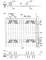
まず、サーボ信号について説明する。本発明で用いられるサーボ信号は磁気記録により記録・再生されるもので、信号の形態(サーボパターン)は任意のものを用いることができる。これらには、上述した振幅変調方式やTBS(Timing Based Servo)方式等が挙げられる。図2は、TBS方式を採用した本発明の実施形態に係る磁気テープの説明図で、(a)は、サーボ信号を書き込んで、サーボバンドを設けるときに使用する記録信号を示す図、(b)は磁気テープの磁化状態を説明する拡大平面図、(c)は磁気テープのサーボバンドから読み取ったサーボ信号を示す図である。
[Servo signal]
First, the servo signal will be described. The servo signal used in the present invention is recorded / reproduced by magnetic recording, and any signal form (servo pattern) can be used. These include the above-described amplitude modulation system, TBS (Timing Based Servo) system, and the like. FIG. 2 is an explanatory diagram of a magnetic tape according to an embodiment of the present invention that adopts the TBS method. FIG. 2A is a diagram showing a recording signal used when a servo signal is written and a servo band is provided. ) Is an enlarged plan view for explaining the magnetization state of the magnetic tape, and (c) is a diagram showing a servo signal read from a servo band of the magnetic tape.
図2(b)に示すように、本発明の実施形態に係る磁気テープMT1には、各々テープの長手方向に伸びるサーボバンドSB1が、幅方向に複数設けられ、各サーボバンドSB1の間には、データバンドDB1が設けられている。各サーボバンドSB1は、磁気テープMT1の長手方向のうち、順方向に磁化されている。図2(b)においては、小さい矢印により磁化されている方向を示している。そして、図2(a)に示すように、記録電流としてゼロ電流(ZC1)とプラスパルス電流(PP1)とからなる記録パルス電流PC1を流すことにより、サーボバンドSB1を逆方向に磁化してサーボ信号SS1が書き込まれている。サーボ信号SS1は、磁気テープMT1の走行方向に対し正の傾斜角をなす2本の縞状に磁化された部分であるバーストBaと、この部分に続く、走行方向に対し負の傾斜角をなす2本の縞状に磁化された部分であるバーストBbにより一つのサーボパターンSP1を形成し、このサーボパターンSP1が所定の間隔で長手方向に繰り返し形成されてサーボ信号SS1が構成されている。
そして、各サーボバンドSB1間のデータバンドDB1も一様に順方向に磁化されている。もちろん、図2(b)に示した磁気テープMT1は、データが未記録のものであって、データが記録されたときには、データバンドDB1にデータの内容に応じて逆方向や順方向に磁化された部分が形成される。
なお、本実施形態では、2本ずつの正、負に傾斜した縞で、サーボパターンSP1を構成しているが、例えば、5本の正、負に傾斜した縞で構成したり、5本の正、負に傾斜した縞と、4本の正、負に傾斜した縞とを交互に形成するなど、適宜変形が可能である。また、図2においては、わかりやすくするため、サーボパターンSP1を磁気テープMT1に対し、誇張して描いている。
As shown in FIG. 2B, the magnetic tape MT1 according to the embodiment of the present invention is provided with a plurality of servo bands SB1 extending in the longitudinal direction of the tape in the width direction, and between the servo bands SB1. A data band DB1 is provided. Each servo band SB1 is magnetized in the forward direction in the longitudinal direction of the magnetic tape MT1. In FIG.2 (b), the direction magnetized by the small arrow is shown. Then, as shown in FIG. 2 (a), a recording pulse current PC1 composed of a zero current (ZC1) and a plus pulse current (PP1) is passed as a recording current, whereby the servo band SB1 is magnetized in the reverse direction and servoed. Signal SS1 is written. The servo signal SS1 has a burst Ba which is a magnetized in two stripes having a positive inclination angle with respect to the traveling direction of the magnetic tape MT1, and a negative inclination angle with respect to the traveling direction following this portion. One servo pattern SP1 is formed by a burst Bb which is a magnetized portion of two stripes, and this servo pattern SP1 is repeatedly formed in the longitudinal direction at a predetermined interval to form a servo signal SS1.
The data band DB1 between the servo bands SB1 is also uniformly magnetized in the forward direction. Of course, the magnetic tape MT1 shown in FIG. 2 (b) is an unrecorded data, and when data is recorded, it is magnetized in the data band DB1 in the reverse direction or the forward direction depending on the data content. The part is formed.
In the present embodiment, the servo pattern SP1 is configured by two positive and negatively inclined stripes. However, for example, the servo pattern SP1 is configured by five positive and negatively inclined stripes or five. Modifications can be made as appropriate, such as alternately forming positive and negative inclined stripes and four positive and negative inclined stripes. In FIG. 2, the servo pattern SP1 is exaggerated with respect to the magnetic tape MT1 for easy understanding.
また、図2(b)には、磁気テープMT1に対する磁気ヘッドHの位置関係を示した。磁気ヘッドHは、サーボ信号SS1を読み取るためのサーボ信号読取素子SHが、複数のサーボバンドSB1の間隔と同じ間隔で磁気テープMT1の幅方向(以下、単に「幅方向」という)に並んで配設されている。この読取素子SHの幅方向のディメンジョンは、各サーボバンドSB1の幅より十分小さく設定されている。そして、各サーボ信号読取素子SHの間には、データバンドDB1に信号を記録するため、複数の記録素子WHが幅方向に2列に並んで配設されている。更に、記録素子WHの間には、複数の再生素子RHが幅方向に一列に並んで配設されている。 FIG. 2B shows the positional relationship of the magnetic head H with respect to the magnetic tape MT1. In the magnetic head H, servo signal reading elements SH for reading the servo signal SS1 are arranged side by side in the width direction of the magnetic tape MT1 (hereinafter simply referred to as “width direction”) at the same intervals as the intervals of the plurality of servo bands SB1. It is installed. The dimension in the width direction of the reading element SH is set to be sufficiently smaller than the width of each servo band SB1. Between the servo signal reading elements SH, a plurality of recording elements WH are arranged in two rows in the width direction in order to record signals in the data band DB1. Further, a plurality of reproducing elements RH are arranged in a line in the width direction between the recording elements WH.
以上のような磁気テープMT1に対し、磁気テープドライブ(図示せず)の磁気ヘッドHでデータの記録・再生を行うときには、サーボ信号読取素子SHでサーボ信号SS1が読み取られる。サーボ信号SS1のサーボパターンSP1は、磁気テープMT1の走行方向(=長手方向)に対し傾斜し、互いに非平行な縞により形成されていることから、サーボ信号読取素子SHがサーボ信号SS1を読み取ってパルスを検出するタイミングは、磁気テープMT1と磁気ヘッドHの幅方向についての相対位置によって異なる。そのため、パルスを読み取るタイミング(位相のずれ)が所定の条件になるように磁気ヘッドHの位置を制御することにより、データバンドDB1の所定のトラックへ正確に記録素子WH又は再生素子RHを位置させることができる。 When data is recorded / reproduced with respect to the magnetic tape MT1 as described above by the magnetic head H of the magnetic tape drive (not shown), the servo signal SS1 is read by the servo signal reading element SH. The servo pattern SP1 of the servo signal SS1 is inclined with respect to the running direction (= longitudinal direction) of the magnetic tape MT1 and is formed by stripes that are not parallel to each other. Therefore, the servo signal reading element SH reads the servo signal SS1. The timing for detecting the pulse differs depending on the relative position of the magnetic tape MT1 and the magnetic head H in the width direction. Therefore, the recording element WH or the reproducing element RH is accurately positioned on a predetermined track of the data band DB1 by controlling the position of the magnetic head H so that the pulse reading timing (phase shift) becomes a predetermined condition. be able to.
この際、サーボ信号読取素子SHがサーボ信号SS1を読み取った出力(ピーク電圧値)は、信号が記録されていない部分と、信号が記録されている部分との切り替わりにおける磁気の変化率又は変化量に依存する。そして、本実施形態では、順方向に磁化された地のサーボバンドSB1の部分から逆方向に磁化されたサーボパターンSP1の切り替わりの部分で順方向から逆方向へ大きく磁気の向きが変わる。
また、逆方向に磁化されたサーボパターンSP1の部分から順方向に磁化された地のサーボバンドSB1の部分に切り替わるところでも逆方向から順方向へ大きく磁気の向きが変わる。そのため、この大きな磁気変化に応じて、図2(c)に示すように、サーボバンドからの読取信号は出力変動の大きな信号となる。したがって、サーボ信号SS1のSN比を向上させることができる。
At this time, the output (peak voltage value) obtained by reading the servo signal SS1 by the servo signal reading element SH is the rate of change or amount of change in magnetism when switching between a portion where no signal is recorded and a portion where a signal is recorded. Depends on. In this embodiment, the direction of magnetism changes greatly from the forward direction to the reverse direction at the switching portion of the servo pattern SP1 magnetized in the reverse direction from the portion of the ground servo band SB1 magnetized in the forward direction.
Also, the direction of magnetism greatly changes from the reverse direction to the forward direction even when the portion of the servo pattern SP1 magnetized in the reverse direction switches to the portion of the ground servo band SB1 magnetized in the forward direction. Therefore, in response to this large magnetic change, as shown in FIG. 2C, the read signal from the servo band becomes a signal with a large output fluctuation. Therefore, the SN ratio of the servo signal SS1 can be improved.
また、サーボ信号SS1の記録は、少なくともサーボバンドSB1を長手方向の順方向に磁化する第一工程と、逆方向に磁化するための単一方向の磁束を誘導させる記録パルス電流PC1を、サーボ信号記録ヘッド(図示せず)に付与することにより、サーボバンドSB1上にサーボ信号SS1を書き込む第二工程とを有する手段により行われる(以下、前記第一工程と前記第二工程とを経てサーボ信号を記録する手段を双方向磁化手段という)。
前記第一工程においてサーボバンドSB1を長手方向の順方向に磁化するには、磁気ヘッドを用いてサーボバンドSB1を直接磁化しても良いし(以下、「双方向磁化1」という)、希土類磁石等の永久磁石を用いて、テープ全体を長手方向の順方向に磁化しても良い(以下、「双方向磁化2」という)。後者の方法を用いた場合には、図2(b)に示すように、データバンドDB1のようにサーボバンド以外の部分も一様に順方向に磁化される。なお、本実施形態においては、サーボバンドSB1の地の部分を順方向に磁化し、サーボパターンSP1の部分を逆方向に磁化したが、これとは逆に、サーボバンドSB1の地の部分を逆方向に磁化し、サーボパターンSP1の部分を順方向に磁化しても構わない。また、本実施形態では図2(b)に示すように、データバンドDB1が一様に順方向に磁化されているが、別途交流消磁工程を設けて、データバンドDB1を消磁しても良い。
In addition, the servo signal SS1 is recorded by using at least a first step for magnetizing the servo band SB1 in the forward direction of the longitudinal direction and a recording pulse current PC1 for inducing a single direction magnetic flux for magnetizing in the reverse direction. By applying to the recording head (not shown), it is performed by means having a second step of writing the servo signal SS1 on the servo band SB1 (hereinafter referred to as the servo signal through the first step and the second step). The means for recording is called bidirectional magnetization means).
In order to magnetize the servo band SB1 in the forward direction in the longitudinal direction in the first step, the servo band SB1 may be directly magnetized using a magnetic head (hereinafter referred to as “
前記双方向磁化手段においては、少なくとも第一の工程と第二の工程がこの順に含まれていればよく、適宜他の工程を設けることができる。例えば、第一の工程の後にテープ裁断工程を設け、その後第二の工程を施してもよい。 In the bidirectional magnetization means, it is sufficient that at least the first step and the second step are included in this order, and other steps can be appropriately provided. For example, a tape cutting step may be provided after the first step, and then the second step may be performed.
また、本実施形態ではサーボ信号記録ヘッドを用いてサーボ信号SS1を書き込んだが、サーボ信号SS1のパターンを凹凸形状あるいは埋め込み構造で予め形成させたマスター担体(パターンドマスター)に、サーボ信号SS1が書き込まれる媒体を密着させた状態で、転写用磁界を印加してマスター担体に担持した情報に対応するサーボ信号SS1を転写する、いわゆる磁気転写法を用いても構わない。 In this embodiment, the servo signal SS1 is written by using the servo signal recording head. However, the servo signal SS1 is written on a master carrier (patterned master) in which the pattern of the servo signal SS1 is formed in an uneven shape or embedded structure in advance. A so-called magnetic transfer method may be used in which a servo signal SS1 corresponding to information carried on the master carrier is transferred by applying a transfer magnetic field in a state where the medium to be adhered is in close contact.
[記録再生方法]
本発明の磁気記録媒体は、線記録密度が100kfci以上、記録トラック幅(記録素子WHで記録されたトラックの幅)と再生トラック幅(再生素子RHで読み取る幅)の差が0〜16μmである磁気記録再生装置で使用されるのが好ましい。すなわち、記録トラック幅と再生トラック幅の差が16μmを超えるシステムの場合は、仮にサーボ信号SS1の読取信号RSのSN比が小さいために高精度に磁気ヘッドHの位置を制御できず数μm程度変動しても、記録トラック幅が再生トラック幅に比べて充分に広いため磁気ヘッドHの再生素子RHは記録トラック上を問題なく走行できる。しかし、記録トラック幅と再生トラック幅の差を16μm以下にせざるを得ないような線記録密度が高い磁気記録再生装置では、記録トラックのピッチにあわせてサーボ信号読取素子SHの幅も小さくなることから、検出できるサーボ信号SS1の磁化量の変化も小さくなり、読取信号RSのSN比が劣化する。その結果、磁気記録再生装置において、サーボ信号SS1を正確に読み取ることができなくなり、磁気ヘッドHの位置制御を高精度に行うことが困難となる。したがって、本発明の磁気記録媒体の効果は、線記録密度が高い磁気記録再生装置を使用したときに顕著となる。
[Recording and playback method]
In the magnetic recording medium of the present invention, the linear recording density is 100 kfci or more, and the difference between the recording track width (the width of the track recorded by the recording element WH) and the reproducing track width (the width read by the reproducing element RH) is 0 to 16 μm. It is preferably used in a magnetic recording / reproducing apparatus. That is, in the case of a system in which the difference between the recording track width and the reproduction track width exceeds 16 μm, the SN ratio of the read signal RS of the servo signal SS1 is small, so that the position of the magnetic head H cannot be controlled with high accuracy and is about several μm. Even if it fluctuates, since the recording track width is sufficiently wider than the reproducing track width, the reproducing element RH of the magnetic head H can run on the recording track without any problem. However, in a magnetic recording / reproducing apparatus having a high linear recording density in which the difference between the recording track width and the reproducing track width must be 16 μm or less, the width of the servo signal reading element SH becomes smaller in accordance with the recording track pitch. Therefore, the change in the magnetization amount of the servo signal SS1 that can be detected is also reduced, and the SN ratio of the read signal RS is degraded. As a result, in the magnetic recording / reproducing apparatus, the servo signal SS1 cannot be read accurately, and it becomes difficult to control the position of the magnetic head H with high accuracy. Therefore, the effect of the magnetic recording medium of the present invention becomes remarkable when a magnetic recording / reproducing apparatus having a high linear recording density is used.
線記録密度は100kfci以上とすることが好ましく、より好ましくは120kfci以上、更に好ましくは140kfci以上である。 The linear recording density is preferably 100 kfci or more, more preferably 120 kfci or more, and still more preferably 140 kfci or more.
記録トラック幅は、25μm以下が好ましく、15μm以下が更に好ましい。
再生トラック幅は、15μm以下が好ましく、10μm以下が更に好ましい。
記録トラック幅と再生トラック幅の差は0〜16μmとすることが好ましく、より好ましくは0〜12μm、更に好ましくは0〜8μmである。
また、本発明の磁気記録媒体の効果は、長手方向に双方向の記録・再生を行うリニアサーペンタイン方式で顕著に発揮される。
The recording track width is preferably 25 μm or less, and more preferably 15 μm or less.
The reproduction track width is preferably 15 μm or less, and more preferably 10 μm or less.
The difference between the recording track width and the reproduction track width is preferably 0 to 16 μm, more preferably 0 to 12 μm, and still more preferably 0 to 8 μm.
The effect of the magnetic recording medium of the present invention is remarkably exhibited in a linear serpentine system that performs bidirectional recording / reproduction in the longitudinal direction.
[層構成]
続いて、本発明の磁気記録媒体の層構成について、好適な例を説明する。本発明においては、ベースフィルム上に、非磁性粉末と結合剤とを少なくとも含む非磁性層を有し、更に、その上に磁性層を有したものが好ましい。このような磁気記録媒体では、磁性層の下層に、非磁性粉末と結合剤とを少なくとも含む非磁性層が設けられているため、磁性層の表面粗さが適正な値となり、サーボエラーの発生頻度を抑えることができる。
また、磁気記録媒体の走行耐久性向上のために、磁性層が設けられた側と反対側のベースフィルム上にバックコート層を有していても良い。また、その厚み構成は、ベースフィルムが1〜100μm、好ましくは4〜80μmであり、磁性層と非磁性層とを合わせた厚みが、ベースフィルムの厚みの1/100〜2倍の範囲であることが好ましく、より好ましくは1/100〜1倍、更に好ましくは1/100〜30/100の範囲である。バックコート層を設けた場合は、バックコート層の厚みが0.1〜2μm、好ましくは0.3〜1.0μm、更に好ましくは0.3〜0.6μmである。また、ベースフィルムと非磁性層との間に密着性向上のための下塗り層を設けても構わない。この下塗り層厚みは0.01〜2μm、好ましくは0.02〜0.5μmである。なお、この下塗り層には公知のものが用いられる。また、本発明の磁気記録媒体には、非磁性層、磁性層、バックコート層以外の層が含まれていても良い。例えば、第2の磁性層、クッション層、オーバーコート層、接着層、保護層を有していても良い。これらの層は、その機能を有効に発揮することができるように適切な位置に設けることができる。
[Layer structure]
Next, a preferred example of the layer structure of the magnetic recording medium of the present invention will be described. In the present invention, it is preferable that the base film has a nonmagnetic layer containing at least a nonmagnetic powder and a binder, and further has a magnetic layer thereon. In such a magnetic recording medium, a nonmagnetic layer containing at least a nonmagnetic powder and a binder is provided below the magnetic layer, so that the surface roughness of the magnetic layer becomes an appropriate value and a servo error occurs. The frequency can be reduced.
In order to improve the running durability of the magnetic recording medium, a back coat layer may be provided on the base film on the side opposite to the side on which the magnetic layer is provided. The thickness of the base film is 1 to 100 μm, preferably 4 to 80 μm, and the combined thickness of the magnetic layer and the nonmagnetic layer is 1/100 to 2 times the thickness of the base film. It is preferably 1/100 to 1 time, more preferably 1/100 to 30/100. When the backcoat layer is provided, the thickness of the backcoat layer is 0.1 to 2 μm, preferably 0.3 to 1.0 μm, and more preferably 0.3 to 0.6 μm. Further, an undercoat layer may be provided between the base film and the nonmagnetic layer for improving adhesion. The thickness of the undercoat layer is 0.01 to 2 μm, preferably 0.02 to 0.5 μm. In addition, a well-known thing is used for this undercoat. Further, the magnetic recording medium of the present invention may contain a layer other than the nonmagnetic layer, the magnetic layer, and the backcoat layer. For example, you may have a 2nd magnetic layer, a cushion layer, an overcoat layer, an adhesive layer, and a protective layer. These layers can be provided at appropriate positions so that their functions can be effectively exhibited.
[磁性層]
本発明で用いられる磁性層は、磁性粉末を結合剤に分散して得られた塗布液をベースフィルム上に塗布して得られる。塗布の方法には、ベースフィルム上に磁性層用塗布液を直接塗布する方法、ベースフィルム上に非磁性層を設けた後で磁性層用塗布液を塗布する方法、ベースフィルム上に非磁性層用塗布液と磁性層用塗布液とを同時に塗布する方法等がある。磁性層の厚みは10〜180nm、好ましくは30〜180nm、更に好ましくは40〜160nmである。磁性層の厚みを10nm以上とすることで、良好なサーボ信号出力を確保できる。また、180nm以下とすることで、書き込まれたサーボ信号の分解能が向上し、サーボ信号の高SN比が得られる。
磁性層の保磁力Hcは127〜356kA/m、好ましくは142〜316kA/m、更に好ましくは158〜177kA/mである。Hcを127kA/m以上とすることで、高い出力が得られ、記録波長が小さくなっても反磁界の影響を低減することができる。Hcが356kA/mを超えると磁気ヘッドでの記録が困難になるため、Hcを356kA/m以下とすることが好ましい。
磁性層の残留磁化と厚みとの積(Mrt)は5×10⁻¹⁰〜7.5×10⁻⁸T・m、好ましくは5×10⁻¹⁰〜5×10⁻⁸T・m、更に好ましくは5×10⁻¹⁰〜3×10⁻⁸T・mである。Mrtを5×10⁻¹⁰〜7.5×10⁻⁸T・mとすることで、MR素子が飽和するのを防ぎ、ノイズを低減させることができる。
[Magnetic layer]
The magnetic layer used in the present invention is obtained by applying a coating solution obtained by dispersing magnetic powder in a binder onto a base film. The coating method includes a method of directly coating the magnetic layer coating liquid on the base film, a method of coating the magnetic layer coating liquid after providing the nonmagnetic layer on the base film, and a nonmagnetic layer on the base film. For example, there is a method of simultaneously applying the coating liquid for magnetic layer and the coating liquid for magnetic layer. The thickness of the magnetic layer is 10 to 180 nm, preferably 30 to 180 nm, more preferably 40 to 160 nm. By setting the thickness of the magnetic layer to 10 nm or more, a satisfactory servo signal output can be ensured. Further, by setting the thickness to 180 nm or less, the resolution of the written servo signal is improved, and a high SN ratio of the servo signal can be obtained.
The coercive force Hc of the magnetic layer is 127 to 356 kA / m, preferably 142 to 316 kA / m, and more preferably 158 to 177 kA / m. By setting Hc to 127 kA / m or more, a high output can be obtained, and the influence of the demagnetizing field can be reduced even when the recording wavelength is reduced. When Hc exceeds 356 kA / m, recording with a magnetic head becomes difficult, so Hc is preferably 356 kA / m or less.
The product (Mrt) of remanent magnetization and thickness of the magnetic layer is 5 × 10 −10 to 7.5 × 10 −8 T · m, preferably 5 × 10 −10 to 5 × 10 −8 T · m, more preferably Is 5 × 10 −10 to 3 × 10 −8 T · m. By setting Mrt to 5 × 10 −10 to 7.5 × 10 −8 T · m, saturation of the MR element can be prevented and noise can be reduced.
磁性層の長手方向におけるMrtの変動率は、30%以下、好ましくは25%以下、更に好ましくは20%以下である。Mrtの変動率を30%以下とすることで、良好なサーボ信号およびデータ信号のSN比が得られる。
Mrtの変動率を適正な範囲にするためには種々の方法があり、例えば以下に示すような方法を用いることができる。
1)磁性層用塗布液を直接ベースフィルム上に塗布する方法では、ベースフィルムの長手方向の厚み変動率を30%以下にし、かつ磁性層用塗布液を送液するポンプの脈動を小さくする。
2)非磁性層を用いる方法では、1)と同様にベースフィルムの長手方向の厚み変動率を30%以下にし、かつ磁性層および非磁性層用塗布液を送液するポンプの脈動を小さくする。なお、非磁性層用塗布液にチクソトロピックな塗布液を用いると、Mrtの変動率をより抑えることができる。また、非磁性層の乾燥後に磁性層用塗布液を塗布するいわゆるWet on dry方式にすれば、Mrtの変動率をより一層抑えることができる。非磁性層の乾燥後、磁性層用塗布液を塗布する前にカレンダ工程を設けても構わない。
The variation rate of Mrt in the longitudinal direction of the magnetic layer is 30% or less, preferably 25% or less, more preferably 20% or less. By setting the variation rate of Mrt to 30% or less, a good SN ratio of the servo signal and the data signal can be obtained.
There are various methods for setting the variation rate of Mrt within an appropriate range. For example, the following method can be used.
1) In the method of directly applying the magnetic layer coating liquid onto the base film, the thickness variation rate in the longitudinal direction of the base film is set to 30% or less, and the pulsation of the pump for feeding the magnetic layer coating liquid is reduced.
2) In the method using a nonmagnetic layer, the thickness variation rate in the longitudinal direction of the base film is set to 30% or less as in 1), and the pulsation of the pump for feeding the coating liquid for the magnetic layer and the nonmagnetic layer is reduced. . If a thixotropic coating solution is used as the coating solution for the nonmagnetic layer, the variation rate of Mrt can be further suppressed. Further, if the so-called wet on dry method is used in which the magnetic layer coating liquid is applied after the nonmagnetic layer is dried, the variation rate of Mrt can be further suppressed. After drying the nonmagnetic layer, a calendar process may be provided before applying the magnetic layer coating solution.
磁性層の長手方向のスイッチングフィールドディストリビューション(前記磁性層の磁化反転性を表す値で、以下「SFD」とする)は0.10〜0.70、好ましくは0.15〜0.65、更に好ましくは0.15〜0.60である。SFDは、図1に示すように、印加磁場(H)と記録媒体の磁化(M)との関係を表す磁化曲線(図1(a))の微分曲線(図1(b))から算出される。ここで、図1(b)に示すdM/dH−H曲線のピーク半値幅をΔHとし、記録媒体の保磁力をHcとしたときに、SFD=ΔH/Hcで定義する。このSFDが小さいほど磁化の立ち上がりが急峻であり、このために記録信号の磁化反転領域の幅が狭くなり、良好な磁化反転性を示す。
SFDを0.70以下とすることにより、磁化反転領域の幅を狭くすることができ、良好なサーボ信号のSN比が得られる。
また、SFDは磁性粉末粒子の粒度分布がシャープであるほど小さくなる。この粒度分布をシャープにするには、磁性粉末の生成反応系をできるだけ均一にするとともに、生成した磁性粉末に、公知の分布改良処理を施せば良い。なお、前記処理を施しても、SFDが0.10より小さくなるように粒度分布を調整するのは困難であるため、SFDの下限値を0.10とした。
また、WYKO社製 HD−2000にて測定した磁性層の中心面平均表面粗さSRaは1〜5nmであることが好ましく、1.5〜4.5nmであることがより好ましい。SRaを上記範囲にすることによってエラーレートを抑えることができる。
Switching field distribution in the longitudinal direction of the magnetic layer (a value representing the magnetization reversibility of the magnetic layer, hereinafter referred to as “SFD”) is 0.10 to 0.70, preferably 0.15 to 0.65, Preferably it is 0.15-0.60. As shown in FIG. 1, the SFD is calculated from a differential curve (FIG. 1 (b)) of a magnetization curve (FIG. 1 (a)) representing the relationship between the applied magnetic field (H) and the magnetization (M) of the recording medium. The Here, when the peak half width of the dM / dH-H curve shown in FIG. 1B is ΔH and the coercive force of the recording medium is Hc, it is defined as SFD = ΔH / Hc. The smaller the SFD, the steeper the rise of magnetization. For this reason, the width of the magnetization inversion region of the recording signal is narrowed, and good magnetization reversibility is exhibited.
By setting the SFD to 0.70 or less, the width of the magnetization switching region can be narrowed, and an excellent SN ratio of the servo signal can be obtained.
Further, the SFD becomes smaller as the particle size distribution of the magnetic powder particles becomes sharper. In order to sharpen this particle size distribution, the magnetic powder production reaction system should be made as uniform as possible, and the produced magnetic powder may be subjected to a known distribution improving process. In addition, even if it performs the said process, since it is difficult to adjust a particle size distribution so that SFD may become smaller than 0.10, the lower limit of SFD was set to 0.10.
Moreover, the center plane average surface roughness SRa of the magnetic layer measured with HD-2000 manufactured by WYKO is preferably 1 to 5 nm, and more preferably 1.5 to 4.5 nm. By setting SRa within the above range, the error rate can be suppressed.
磁性層の、サーボバンド以外の部分の残留磁化φ0と、該部分に1Tの外部磁場を印加したときの残留磁化φ1の比R(φ0/φ1)は0.01〜0.30、好ましくは0.04〜0,25、更に好ましくは0.04〜0.20である。Rを0.01〜0.30とすることで、データ信号読み取り素子でデータを読み取ったときに高いSN比を得ることができる。
残留磁化φ1の比R(φ0/φ1)を適正な範囲にするためには種々の方法があり、例えば、下に示すような方法を用いることができる。
(1)前記双方向磁化1において永久磁石でテープ全体をヘッドの走行方向の順方向に磁化する際、印加する磁化の大きさを調整する。
(2)データバンドDB1が一様に磁化されており、別途消磁工程を設けてデータバンドDB1を消磁する際の消去磁界の大きさを調整する。
The ratio R (φ 0 / φ 1 ) between the residual magnetization φ 0 of the magnetic layer other than the servo band and the residual magnetization φ 1 when a 1 T external magnetic field is applied to the portion is 0.01 to 0.30. , Preferably 0.04 to 0,25, more preferably 0.04 to 0.20. By setting R to 0.01 to 0.30, a high S / N ratio can be obtained when data is read by the data signal reading element.
There are various methods for setting the ratio R (φ 0 / φ 1 ) of the remanent magnetization φ 1 to an appropriate range. For example, the following method can be used.
(1) When the entire tape is magnetized in the forward direction of the traveling direction of the head with a permanent magnet in the
(2) The data band DB1 is uniformly magnetized, and a demagnetizing step is separately provided to adjust the magnitude of the erasing magnetic field when the data band DB1 is demagnetized.
本発明の磁性層に用いられる磁性粉末としては、高密度記録を可能とするため、強磁性金属粉末又は六方晶フェライト磁性粉末が好ましい。強磁性金属粉末の場合は、例えば、Feを主体とした針状粉末で、Co、Mn、Ni、Sm、Nb等が含まれる合金粉末が用いられる。
また、Al、Y等の化合物を焼結防止剤として用いることができる。強磁性金属粉末の平均長軸長は30〜100nmであることが好ましく、35〜90nmであることがより好ましく、40〜80nmであることが更に好ましい。平均長軸長を100nm以下とすることで、ノイズが低減でき、良好なサーボ信号およびデータ信号のSN比が得られる。また、平均長軸長を30nm以上とすることで良好な保持力Hcが確保できる。
また、強磁性金属粉末の平均針状比は3〜10であることが好ましく、3〜8であることがより好ましく、4〜8であることが更に好ましい。
強磁性金属粉末の長軸長の変動率[(長軸長の標準偏差)/(長軸長の平均値)]は30%以下であることが好ましく、25%以下であることがより好ましく、20%以下であることが更に好ましい。長軸長の変動率を30%以下とすることで、長軸長の異なった磁性粒子が混在することによるノイズを低減してサーボ信号およびデータ信号のSN比を向上できる。
強磁性金属粉末の飽和磁化量σsは70〜150A・m2/kgであることが好ましく、80〜140A・m2/kgであることがより好ましく、90〜125A・m2/kgであることが更に好ましい。また、その保磁力Hcは127〜356kA/mであることが好ましく、142〜316kA/mであることがより好ましく、158〜177kA/mであることが更に好ましい。
強磁性金属粉末のBET法による比表面積(SBET)は、40〜80m2/gであることが好ましく、より好ましくは45〜70m2/gである。BET法による比表面積(SBET)が40m2/g以上であれば、ノイズが低減され、80m2/g以下であれば、良好な表面性を得ることができる。
The magnetic powder used in the magnetic layer of the present invention is preferably a ferromagnetic metal powder or a hexagonal ferrite magnetic powder in order to enable high density recording. In the case of a ferromagnetic metal powder, for example, an acicular powder mainly composed of Fe and an alloy powder containing Co, Mn, Ni, Sm, Nb, or the like is used.
Further, compounds such as Al and Y can be used as sintering inhibitors. The average major axis length of the ferromagnetic metal powder is preferably 30 to 100 nm, more preferably 35 to 90 nm, and still more preferably 40 to 80 nm. By setting the average major axis length to 100 nm or less, noise can be reduced, and a good SN ratio of servo signals and data signals can be obtained. Moreover, favorable holding power Hc can be ensured by setting the average major axis length to 30 nm or more.
The average needle ratio of the ferromagnetic metal powder is preferably 3 to 10, more preferably 3 to 8, and still more preferably 4 to 8.
The variation rate of the long axis length of the ferromagnetic metal powder [(standard deviation of long axis length) / (average value of long axis length)] is preferably 30% or less, more preferably 25% or less, More preferably, it is 20% or less. By setting the variation rate of the major axis length to 30% or less, it is possible to reduce noise due to the mixing of magnetic particles having different major axis lengths and improve the SN ratio of the servo signal and the data signal.
Preferably saturation magnetization σs of the ferromagnetic metal powder is 70~150A · m 2 / kg, more preferably 80~140A · m 2 / kg, it is 90~125A · m 2 / kg Is more preferable. The coercive force Hc is preferably 127 to 356 kA / m, more preferably 142 to 316 kA / m, and still more preferably 158 to 177 kA / m.
The specific surface area by BET method of the ferromagnetic metal powder (S BET) is preferably 40 to 80 m 2 / g, more preferably 45~70m 2 / g. If the specific surface area (S BET ) by the BET method is 40 m 2 / g or more, noise is reduced, and if it is 80 m 2 / g or less, good surface properties can be obtained.
六方晶フェライト磁性粉末の場合は、Baフェライトが適している。また、置換元素としてTi等を含んでいても良い。六方晶フェライト磁性粉末の平均板径は15〜50nmであることが好ましく、20〜45nmであることがより好ましく、20〜40nmであることが更に好ましい。強磁性金属粉末を用いる場合と同様、平均板径を50nm以下とすることで、ノイズが低減でき、良好なサーボ信号およびデータ信号のSN比が得られる。また、平均板径を15nm以上とすることで良好な保持力Hcが確保できる。
また、六方晶フェライト磁性粉末の平均板状比は2〜7であることが好ましく、3〜5であることがより好ましい。
六方晶フェライト磁性粉末の板径の変動率[(板径の標準偏差)/(板径の平均値)]は30%以下であることが好ましく、25%以下であることがより好ましく、20%以下であることが更に好ましい。板径の変動率を30%とすることで、板径の異なった磁性粒子が混在することによるノイズを低減してサーボ信号およびデータ信号のSN比を向上できる。
六方晶フェライト磁性粉末の飽和磁化量σsは、40〜80A・m2/kgであることが好ましく、45〜75A・m2/kgであることがより好ましく、45〜65A・m2/kgであることが更に好ましい。また、その保磁力Hcは127〜356kA/mであることが好ましく、142〜316kA/mであることがより好ましく、158〜177kA/mであることが更に好ましい。
上記粒子サイズの範囲内におけるBET法による比表面積は10〜200m2/gである。この比表面積は、概ね粒子板径と板厚からの計算値と符合する。
In the case of hexagonal ferrite magnetic powder, Ba ferrite is suitable. Further, Ti or the like may be included as a substitution element. The average plate diameter of the hexagonal ferrite magnetic powder is preferably 15 to 50 nm, more preferably 20 to 45 nm, and still more preferably 20 to 40 nm. As in the case of using the ferromagnetic metal powder, by setting the average plate diameter to 50 nm or less, noise can be reduced and a good SN ratio of servo signals and data signals can be obtained. Moreover, the favorable holding force Hc is securable by making an average board diameter into 15 nm or more.
The average plate ratio of the hexagonal ferrite magnetic powder is preferably 2 to 7, and more preferably 3 to 5.
The plate diameter variation rate [(standard deviation of plate diameter) / (average value of plate diameter)] of the hexagonal ferrite magnetic powder is preferably 30% or less, more preferably 25% or less, and 20%. More preferably, it is as follows. By setting the variation rate of the plate diameter to 30%, it is possible to reduce noise caused by the mixing of magnetic particles having different plate diameters and improve the SN ratio of the servo signal and the data signal.
Saturation magnetization σs of the hexagonal ferrite magnetic powder is preferably 40~80A · m 2 / kg, more preferably 45~75A · m 2 / kg, in 45~65A · m 2 / kg More preferably it is. The coercive force Hc is preferably 127 to 356 kA / m, more preferably 142 to 316 kA / m, and still more preferably 158 to 177 kA / m.
The specific surface area according to the BET method within the above particle size range is 10 to 200 m 2 / g. This specific surface area approximately agrees with the calculated value from the particle plate diameter and plate thickness.
本発明の磁性層に用いられる結合剤には公知のものを使用できる。例えば、塩化ビニル共重合体、ポリウレタン樹脂、アクリル樹脂等、又はこれらの混合物が挙げられる。また、これらの樹脂の数平均分子量は2〜10万、好ましくは3〜8万である。なお、これらの樹脂には磁性粉末の分散性を向上させるために極性基を導入すると良い。極性基としては−COOM、−SO3M、−P=O(OM)2(Mは水素原子又はアルカリ金属)が知られている。
更に、磁性層には、必要に応じて、研磨剤、カーボンブラック、潤滑剤等を含有させることができる。研磨剤を含有させる場合は、平均粒子サイズが10〜300nm、かつ、磁性層厚みの2倍以下のものが好ましい。
Known binders can be used for the binder used in the magnetic layer of the present invention. For example, a vinyl chloride copolymer, a polyurethane resin, an acrylic resin, etc., or a mixture thereof can be used. The number average molecular weight of these resins is 2 to 100,000, preferably 3 to 80,000. In order to improve the dispersibility of the magnetic powder, polar groups are preferably introduced into these resins. Examples of the polar group -COOM, -SO 3 M, -P = O (OM) 2 (M is a hydrogen atom or an alkali metal) is known.
Furthermore, the magnetic layer can contain an abrasive, carbon black, a lubricant and the like as required. When an abrasive is contained, those having an average particle size of 10 to 300 nm and not more than twice the thickness of the magnetic layer are preferred.
[非磁性層]
本発明で用いられる非磁性層は、非磁性粉末と結合剤とを少なくとも含むものが好ましい。非磁性粉末としては公知のものが使用可能で、これらにはTiO2、Fe2O3、Al2O3、CeO2、ZrO2、BaSO4、ZnO、カーボンブラック、グラファイト等が挙げられる。これらの中でもTiO2、α−Fe2O3が好ましく、これらとカーボンブラックを併用することがより好ましい。また、極性基が導入された樹脂を結合剤に用いる場合は、金属酸化物が分散性の点で優れる。これら非磁性粉末の平均粒子サイズ(針状の場合は平均長軸長)は10〜300nm、好ましくは30〜200nmであり、形状は粒状、針状、サイコロ状のいずれでも良い。また、非磁性粉末は必要に応じて複数種類用いられる。例えば導電性付与のために非磁性酸化物、カーボンブラック等を混合することも可能である。また、非磁性層に用いる結合剤は、磁性層と同じく公知のものが用いられる。更に、非磁性層には、必要に応じて、帯電防止剤、潤滑剤等を含有させることができる。
[Nonmagnetic layer]
The nonmagnetic layer used in the present invention preferably contains at least a nonmagnetic powder and a binder. The nonmagnetic powder can be used known ones, TiO 2 These, Fe 2 O 3, Al 2 O 3, CeO 2, ZrO 2, BaSO 4, ZnO, carbon black, graphite and the like. Among these, TiO 2 and α-Fe 2 O 3 are preferable, and it is more preferable to use these in combination with carbon black. Further, when a resin into which a polar group has been introduced is used as a binder, a metal oxide is excellent in terms of dispersibility. These nonmagnetic powders have an average particle size (average major axis length in the case of needles) of 10 to 300 nm, preferably 30 to 200 nm, and the shape may be granular, needle-like, or dice-like. A plurality of types of nonmagnetic powders are used as necessary. For example, a nonmagnetic oxide, carbon black or the like can be mixed to impart conductivity. As the binder used for the nonmagnetic layer, a known binder is used as in the magnetic layer. Furthermore, the nonmagnetic layer can contain an antistatic agent, a lubricant, and the like, if necessary.
[ベースフィルム]
本発明に用いられるベースフィルムは、ポリエチレンテレフタレート、ポリエチレンナフタレート等のポリエステル類、ポリオレフィン類、セルローストリアセテート、ポリカーボネート、ポリアミド(特に好ましくは芳香族ポリアミド)、ポリイミド、ポリアミドイミド、ポリスルフォン、アラミド等の公知のフィルムが使用できる。これらのベースフィルムには予めコロナ放電処理、プラズマ処理、易接着処理、熱処理、除塵処理等を行っても良い。本発明の目的を達成するには、ベースフィルムとして中心線平均粗さRa(カットオフ値:0.25mm)が0.03μm以下、好ましくは0.02μm以下、更に好ましくは0.01μm以下のものを使用する必要がある。また、これらのベースフィルムは、単に中心線平均粗さRaが小さいだけではなく、1μm以上の粗大突起がないことが好ましい。また、表面の粗さ形状は、必要に応じて、ベースフィルムに添加されるフィラーの大きさと量とにより自在にコントロールすることができる。
本発明に用いられるベースフィルムの長手方向のF−5値は、好ましくは5〜50kg/mm2、幅方向のF−5値は、好ましくは3〜30kg/mm2であり、長手方向のF−5値が幅方向のF−5値より高いのが一般的であるが、特に幅方向の強度を高くする必要があるときはその限りでない。また、ベースフィルムの長手方向および幅方向の100℃、30分での熱収縮率は好ましくは3%以下、更に好ましくは1.5%以下であり、80℃、30分での熱収縮率は好ましくは1%以下、更に好ましくは0.5%以下である。また、その破断強度は長手方向および幅方向ともに、好ましくは5〜100kg/mm2であり、その弾性率は、長手方向および幅方向ともに、好ましくは100〜2000kg/mm2である。
[Base film]
Examples of the base film used in the present invention include polyesters such as polyethylene terephthalate and polyethylene naphthalate, polyolefins, cellulose triacetate, polycarbonate, polyamide (particularly preferably aromatic polyamide), polyimide, polyamideimide, polysulfone, and aramid. Can be used. These base films may be previously subjected to corona discharge treatment, plasma treatment, easy adhesion treatment, heat treatment, dust removal treatment and the like. In order to achieve the object of the present invention, the base film has a center line average roughness Ra (cutoff value: 0.25 mm) of 0.03 μm or less, preferably 0.02 μm or less, more preferably 0.01 μm or less. Need to use. In addition, these base films preferably have not only a small center line average roughness Ra but also no coarse protrusions of 1 μm or more. Moreover, the roughness shape of the surface can be freely controlled by the size and amount of the filler added to the base film, if necessary.
The F-5 value in the longitudinal direction of the base film used in the present invention is preferably 5 to 50 kg / mm 2 , and the F-5 value in the width direction is preferably 3 to 30 kg / mm 2. The -5 value is generally higher than the F-5 value in the width direction, but this is not necessarily the case when it is necessary to increase the strength in the width direction. The heat shrinkage rate at 100 ° C. for 30 minutes in the longitudinal direction and the width direction of the base film is preferably 3% or less, more preferably 1.5% or less, and the heat shrinkage rate at 80 ° C. for 30 minutes is Preferably it is 1% or less, More preferably, it is 0.5% or less. Further, the breaking strength in both the longitudinal direction and the cross direction, preferably 5 to 100 kg / mm 2, the modulus of elasticity in both the longitudinal direction and the cross direction, preferably 100 to 2,000 kg / mm 2.
[バックコート層]
本発明に用いられるバックコート層は公知のものが使用できるが、結合剤、およびカーボンブラックを含有するものであることが好ましい。バックコート層は、微粒子で電気伝導性が優れたカーボンブラックを主なフィラーとし、平均粒子サイズの異なる二種類のカーボンブラックを含有させたり、必要により無機質粉末を含有してもよい。例えば、モース硬度5〜9の無機質粉末を含有させることができる。無機質粉末のバックコート層への配合量は、カーボンブラック100質量部に対して、通常、0.5〜150質量部であり、好ましくは0.5〜100質量部である。
[Back coat layer]
The backcoat layer used in the present invention may be a known one, but preferably contains a binder and carbon black. The back coat layer may be composed of carbon black having fine particles and excellent electrical conductivity as a main filler, and may contain two types of carbon blacks having different average particle sizes, or may contain an inorganic powder as required. For example, an inorganic powder having a Mohs hardness of 5 to 9 can be contained. The compounding amount of the inorganic powder in the back coat layer is usually 0.5 to 150 parts by mass, preferably 0.5 to 100 parts by mass with respect to 100 parts by mass of carbon black.
前述のように、バックコート層には、平均粒子サイズの異なる二種類のカーボンブラックを含有させることができる。例えば、平均粒子サイズが15〜50nmの微粒子状カーボンブラックと平均粒子サイズが80〜300nmの粗粒子状カーボンブラックを用いることができる。このように、二種類のカーボンブラックを使用することにより、バックコート層を粗面化しても磁性層への裏写りの少ない磁気記録媒体を得ることができる。 As described above, the backcoat layer can contain two types of carbon black having different average particle sizes. For example, fine particulate carbon black having an average particle size of 15 to 50 nm and coarse particulate carbon black having an average particle size of 80 to 300 nm can be used. Thus, by using two types of carbon black, a magnetic recording medium with little show-through to the magnetic layer can be obtained even when the backcoat layer is roughened.
また、一般に、上記のような微粒子状のカーボンブラックの添加により、バックコート層の表面電気抵抗を低く設定でき、また光透過率も低く設定できる。磁気記録の装置によっては、テープの光透過率を利用し、動作の信号に使用しているものが多くあるため、このような場合には特に微粒子状のカーボンブラックの添加は有効になる。また、微粒子状カーボンブラックは、一般に潤滑剤の保持力に優れ、潤滑剤併用時、摩擦係数の低減化に寄与する。 In general, by adding fine particulate carbon black as described above, the surface electrical resistance of the backcoat layer can be set low, and the light transmittance can also be set low. Depending on the magnetic recording apparatus, there are many which use the light transmittance of the tape and are used for the operation signal. In such a case, the addition of fine carbon black is particularly effective. In addition, the particulate carbon black is generally excellent in the retention of the lubricant and contributes to the reduction of the friction coefficient when used in combination with the lubricant.
一方、平均粒子サイズ80〜300nmの粗粒子状カーボンブラックは、固体潤滑剤としての機能を有しており、またバックコート層の表面に微小突起を形成し、接触面積を低減化して、摩擦係数の低減化に寄与する。 On the other hand, the coarse particulate carbon black having an average particle size of 80 to 300 nm has a function as a solid lubricant, forms fine protrusions on the surface of the backcoat layer, reduces the contact area, and has a friction coefficient. Contributes to the reduction of
本発明で用いることができる微粒子状カーボンブラックの具体的な商品としては、以下のものを挙げることができる。括弧内は、平均粒子サイズを示す。REGAL 99R(38nm)、RAVEN2000B(18nm)、RAVEN1500B(17nm)(以上、コロンビアカーボン社製)、BP800(17nm)(キャボット社製)、PRINTEX90(14nm)、PRINTEX95(15nm)、PRINTEX85(16nm)、PRINTEX75(17nm)(以上、デグサ社製)、#3950(16nm)(三菱化学(株)製)。
また、粗粒子カーボンブラックの具体的な商品の例としては、旭#51(91nm)(旭カーボン社製)、サーマルブラック(270nm)(カーンカルブ社製)、RAVENMTP(275nm)(コロンビアカーボン社製)を挙げることができる。平均粒子サイズ80〜300nmの粗粒子状カーボンブラックは、ゴム用カーボンブラックや、カラー用カーボンブラックより選択することができる。
Specific products of the particulate carbon black that can be used in the present invention include the following. The average particle size is shown in parentheses. REGAL 99R (38 nm), RAVEN2000B (18 nm), RAVEN1500B (17 nm) (manufactured by Columbia Carbon Co., Ltd.), BP800 (17 nm) (manufactured by Cabot Corporation), PRINTERX90 (14 nm), PRINTEX95 (15 nm), PRINTEX85 (16 nm), PRINTEX75 (17 nm) (above, manufactured by Degussa), # 3950 (16 nm) (manufactured by Mitsubishi Chemical Corporation).
As examples of specific products of coarse particle carbon black, Asahi # 51 (91 nm) (manufactured by Asahi Carbon Co., Ltd.), thermal black (270 nm) (manufactured by Khan Calbu Co., Ltd.), RAVENMTP (275 nm) (manufactured by Columbia Carbon Co., Ltd.) Can be mentioned. Coarse particulate carbon black having an average particle size of 80 to 300 nm can be selected from carbon black for rubber and carbon black for color.
本発明において、バックコート層における微粒子状カーボンブラックと粗粒子状カーボンブラックの含有比率(質量比)は、前者:後者=98:2〜75:25の範囲とすることが好ましく、更に好ましくは、95:5〜85:15である。また、バックコート層におけるカーボンブラックの含有量(二種類のカーボンブラックを使用する場合は、微粒子状カーボンブラックと粗粒子状カーボンブラックの合計量)は、結合剤100質量部に対して、通常30〜80質量部の範囲とすることができ、好ましくは、45〜65質量部の範囲である。 In the present invention, the content ratio (mass ratio) of the fine particle carbon black and the coarse particle carbon black in the back coat layer is preferably in the range of the former: the latter = 98: 2 to 75:25, more preferably, 95: 5 to 85:15. In addition, the content of carbon black in the back coat layer (when using two types of carbon black, the total amount of fine carbon black and coarse carbon black) is usually 30 with respect to 100 parts by mass of the binder. It can be made into the range of -80 mass parts, Preferably, it is the range of 45-65 mass parts.
バックコート層に添加することができる無機質粉末としては、平均粉体サイズが80〜250nmでモース硬度が5〜9の無機質粉末が挙げられる。無機質粉末としては、上述した非磁性層に使用される非磁性粉末や研磨剤などと同様のものを使用することができ、中でもα−酸化鉄、α−アルミナ等を用いることが好ましい。無機質粉末のバックコート層への添加量は、結合剤100質量部に対して、好ましくは0.5〜40質量部の範囲であり、更に好ましくは1〜30質量部の範囲である。 Examples of the inorganic powder that can be added to the backcoat layer include inorganic powders having an average powder size of 80 to 250 nm and a Mohs hardness of 5 to 9. As the inorganic powder, those similar to the nonmagnetic powder and abrasive used in the above-described nonmagnetic layer can be used, and among these, α-iron oxide, α-alumina and the like are preferably used. The amount of the inorganic powder added to the backcoat layer is preferably in the range of 0.5 to 40 parts by mass, more preferably in the range of 1 to 30 parts by mass with respect to 100 parts by mass of the binder.
バックコート層に使用する結合剤は、従来公知の熱可塑性樹脂、熱硬化性樹脂、反応型樹脂等を用いることができる。好ましい結合剤は、塩化ビニル樹脂、塩化ビニル−酢酸ビニル樹脂、ニトロセルロース等の繊維素系樹脂、フェノキシ樹脂、ポリウレタン樹脂である。その中でも、塩化ビニル樹脂、塩化ビニル−酢酸ビニル樹脂、ポリウレタン樹脂を用いるのがより好ましい。 As the binder used for the back coat layer, conventionally known thermoplastic resins, thermosetting resins, reactive resins and the like can be used. Preferred binders are vinyl chloride resins, vinyl chloride-vinyl acetate resins, fibrous resins such as nitrocellulose, phenoxy resins, and polyurethane resins. Among these, it is more preferable to use vinyl chloride resin, vinyl chloride-vinyl acetate resin, and polyurethane resin.
バックコート層には、前述の成分以外に、他の任意の成分として、分散剤、潤滑剤を添加することもできる。分散剤としては、例えば、カプリル酸、カプリン酸、ラウリン酸、ミリスチン酸、パルミチン酸、ステアリン酸、ベヘン酸、オレイン酸、エライジン酸、リール酸、リノレン酸、ステアロール酸等の炭素数12〜18個の脂肪酸(RCOOH;Rは炭素数11〜17個のアルキル基、またはアルケニル基)、前記脂肪酸のアルカリ金属またはアルカリ土類金属からなる金属石けん、前記の脂肪酸エステルのフッ素を含有した化合物、前記脂肪酸のアミド、ポリアルキレンオキサイドアルキルリン酸エステル、レシチン、トリアルキルポリオレフィンオキシ第四級アンモニウム塩(アルキルは炭素数1〜5個、オレフィンは、エチレン、プロピレンなど)、硫酸エステル、銅フタロシアニン、沈降性硫酸バリウム等を使用することができる。分散剤は、結合剤樹脂100質量部に対して、0.5〜20質量部の範囲で添加することができる。 In addition to the aforementioned components, a dispersant and a lubricant can be added to the back coat layer as other optional components. Examples of the dispersant include 12 to 18 carbon atoms such as caprylic acid, capric acid, lauric acid, myristic acid, palmitic acid, stearic acid, behenic acid, oleic acid, elaidic acid, reelic acid, linolenic acid, stearic acid, and the like. A fatty acid (RCOOH; R is an alkyl group having 11 to 17 carbon atoms, or an alkenyl group), a metal soap composed of an alkali metal or an alkaline earth metal of the fatty acid, a compound containing fluorine of the fatty acid ester, Fatty acid amide, polyalkylene oxide alkyl phosphate ester, lecithin, trialkyl polyolefinoxy quaternary ammonium salt (alkyl is 1 to 5 carbon atoms, olefin is ethylene, propylene, etc.), sulfate ester, copper phthalocyanine, precipitation Barium sulfate or the like can be used. A dispersing agent can be added in 0.5-20 mass parts with respect to 100 mass parts of binder resin.
バックコート層は、通常の方法に従って非磁性支持体の磁性層が設けられている側とは反対側に設けられる。即ち、前記の各成分を適当な有機溶媒に溶解、分散させた塗布液を調製し、これを常法の塗布方法に従い、塗布、乾燥することにより、非磁性支持体上にバックコート層を設けることができる。本発明において、バックコート層は、その平均表面粗さRaが、20〜30nmであることが好ましく、より好ましくは22〜28nmである。バックコート層の表面粗さは、テープが巻かれた状態でバックコート層の表面が磁性層の表面に転写されることで、再生出力に影響を与えたり、ガイドポールに対する摩擦係数に影響を与えるため、上記の範囲に調整することが好ましい。なお、この表面粗さRaの調整は、バックコート層を塗布形成後、カレンダーによる表面処理工程において、用いるカレンダーロールの材質、その表面性、圧力等の調整により行うことができる。本発明において、バックコート層の厚みは0.1〜2μm、好ましくは0.3〜1.0μm、更に好ましくは0.3〜0.6μmである。 The back coat layer is provided on the side opposite to the side on which the magnetic layer of the nonmagnetic support is provided according to a usual method. That is, a back coating layer is provided on a nonmagnetic support by preparing a coating solution in which each of the above components is dissolved and dispersed in a suitable organic solvent, and coating and drying the coating solution according to a conventional coating method. be able to. In the present invention, the back coat layer preferably has an average surface roughness Ra of 20 to 30 nm, more preferably 22 to 28 nm. The surface roughness of the backcoat layer affects the reproduction output or the coefficient of friction against the guide pole by transferring the surface of the backcoat layer to the surface of the magnetic layer while the tape is wound. Therefore, it is preferable to adjust to the above range. The surface roughness Ra can be adjusted by adjusting the material of the calender roll to be used, its surface property, pressure, and the like in the surface treatment process using the calender after the back coat layer is applied and formed. In the present invention, the back coat layer has a thickness of 0.1 to 2 μm, preferably 0.3 to 1.0 μm, and more preferably 0.3 to 0.6 μm.
[製造方法]
本発明の磁気記録媒体の製造方法について、好適な例を説明すると、製造工程に少なくとも、磁性層用塗布液の調製工程、ベースフィルム上への磁性層用塗布液の塗布工程、希土類磁石等により磁性体を配向させる配向工程、乾燥工程、ローラにより表面の平滑性を高くするためのカレンダ工程、スリット工程、サーボ信号の記録工程を有している方法が好ましい。また、非磁性層を設ける場合は、非磁性層用塗布液の調製工程および塗布工程が別途加わる。以下、非磁性層を設けた本発明の磁気記録媒体の製造方法について説明する。なお、本発明の磁気記録媒体の製造方法は以下に示す方法に限定されず、例えば、必要に応じバックコート層等を設ける工程を加えても良い。
[Production method]
A preferred example of the method for producing a magnetic recording medium of the present invention will be described. The production process includes at least a step of preparing a coating solution for a magnetic layer, a step of applying a coating solution for a magnetic layer on a base film, and a rare earth magnet. A method having an orientation step for orienting the magnetic material, a drying step, a calendar step for increasing the surface smoothness with a roller, a slit step, and a servo signal recording step is preferred. Moreover, when providing a nonmagnetic layer, the preparation process and application | coating process of the coating liquid for nonmagnetic layers are added separately. Hereinafter, a method for producing the magnetic recording medium of the present invention provided with a nonmagnetic layer will be described. In addition, the manufacturing method of the magnetic recording medium of this invention is not limited to the method shown below, For example, you may add the process of providing a backcoat layer etc. as needed.
磁性層および非磁性層用塗布液の調製工程は、少なくとも混練工程および分散工程を有している。また、これらの工程の前後に必要に応じて混合工程を設けても良く、更に、個々の工程はそれぞれ二段階以上に分かれていても構わない。本発明で用いられる強磁性金属粉末、六方晶フェライト磁性粉末、非磁性粉末、結合剤、カーボンブラック、研磨剤、帯電防止剤、潤滑剤、溶剤等すべての原料はどの工程の最初又は途中で添加しても構わない。また、個々の原料を2つ以上の工程で分割して添加しても構わない。例えば、ポリウレタン樹脂を混練工程、分散工程、分散後の粘度調整のための混合工程で分割して投入しても良い。 The preparation process of the coating solution for the magnetic layer and the nonmagnetic layer has at least a kneading process and a dispersion process. Moreover, you may provide a mixing process before and behind these processes as needed, and each process may be divided into two or more steps, respectively. All raw materials such as ferromagnetic metal powder, hexagonal ferrite magnetic powder, nonmagnetic powder, binder, carbon black, abrasive, antistatic agent, lubricant, solvent, etc. used in the present invention are added at the beginning or middle of any process. It doesn't matter. Moreover, you may divide | segment and add each raw material at two or more processes. For example, the polyurethane resin may be divided and added in a kneading step, a dispersing step, and a mixing step for adjusting the viscosity after dispersion.
本発明に用いる残留磁化の高い磁性層を得るには、磁性層用塗布液の混練工程に連続ニーダ、加圧ニーダ等の強い混練力をもつものを使用することが好ましい。ニーダを用いる場合は磁性粉末と、磁性粉末100質量部に対し15〜500質量部の結合剤とが混練処理される。また非磁性層用塗布液を分散させるには、高比重の分散メディアを用いることが好ましい。このような分散メディアには、ジルコニアビーズ、チタニアビーズ、スチールビーズ等が好適である。 In order to obtain a magnetic layer having a high residual magnetization used in the present invention, it is preferable to use a magnetic layer coating liquid having a strong kneading force such as a continuous kneader or a pressure kneader. In the case of using a kneader, the magnetic powder and 15 to 500 parts by mass of a binder with respect to 100 parts by mass of the magnetic powder are kneaded. In order to disperse the coating solution for the nonmagnetic layer, it is preferable to use a dispersion medium having a high specific gravity. As such a dispersion medium, zirconia beads, titania beads, steel beads and the like are suitable.
ベースフィルム上への前記塗布液の塗布工程は公知の方法を使用することができ、例えば、以下に示す方法が挙げられる。
1)グラビア塗布、ロール塗布、ブレード塗布、エクストルージョン塗布装置等により、まず非磁性層用塗布液を塗布し、非磁性層がウェット状態のうちに特公平1−46186号公報、特開昭60−238179号公報、特開平2−265672号公報に開示されているベースフィルム加圧型エクストルージョン塗布装置により磁性層用塗布液を塗布する方法。
2)特開昭63−88080号公報、特開平2−17971号公報、特開平2−265672号公報に開示されているような塗布液通液スリットを2つ内蔵する一つの塗布ヘッドにより、磁性層および非磁性層用塗布液をほぼ同時に塗布する方法。
3)特開平2−174965号公報に開示されているバックアップロール付きエクストルージョン塗布装置により磁性層および非磁性層用塗布液をほぼ同時に塗布する方法。
なお、前記したように、非磁性層用塗布液にチクソトロピックな塗布液を用いる方法やWet on dry方式により塗布する方法を用いれば、Mrtの変動率をより一層抑えることができる。
A well-known method can be used for the application | coating process of the said coating liquid on a base film, For example, the method shown below is mentioned.
1) First, a non-magnetic layer coating solution is applied by a gravure coating, roll coating, blade coating, extrusion coating apparatus, etc., and the non-magnetic layer is in a wet state. A method of applying a coating solution for a magnetic layer by a base film pressure type extrusion coating apparatus disclosed in Japanese Patent No. -238179 and Japanese Patent Laid-Open No. 2-265672.
2) One coating head incorporating two coating liquid passage slits as disclosed in JP-A-63-88080, JP-A-2-17971, and JP-A-2-265672 is used to provide magnetic properties. A method of applying the coating liquid for the layer and the nonmagnetic layer almost simultaneously.
3) A method of applying the coating liquid for the magnetic layer and the non-magnetic layer almost simultaneously using an extrusion coating apparatus with a backup roll disclosed in JP-A-2-174965.
Note that, as described above, if the method using a thixotropic coating solution as the coating solution for the nonmagnetic layer or the method using the wet-on-dry method is used, the variation rate of Mrt can be further suppressed.
また、磁性粉末粒子の凝集による磁気記録媒体の電磁変換特性等の低下を防止するため、特開昭62−95174号公報や特開平1−236968号公報に開示されているような方法により、塗布ヘッド内部の塗布液にせん断を付与することが好ましい。更に、塗布液の粘度について、特開平3−8471号公報に開示されている数値範囲を満たせば、より一層、磁性粉末粒子の凝集を防ぐことができる。 Further, in order to prevent a decrease in electromagnetic conversion characteristics and the like of the magnetic recording medium due to agglomeration of the magnetic powder particles, the coating is performed by a method as disclosed in Japanese Patent Application Laid-Open Nos. 62-95174 and 1-2236968. It is preferable to apply shear to the coating solution inside the head. Furthermore, if the viscosity of the coating solution satisfies the numerical range disclosed in Japanese Patent Laid-Open No. 3-8471, the aggregation of the magnetic powder particles can be further prevented.
磁性体を配向させる配向工程は、例えば、希土類磁石を斜めに交互に配置してランダム配向を行う方法や、ソレノイドで交流磁場を印加してランダム配向を行う方法等の公知の方法を用いることができる。ただし、本発明の磁気記録媒体を得るには強力な配向を行う必要があるため、0.2T以上の希土類磁石による配向方法と、0.1T以上のソレノイドによる配向方法とを併用して用いることが好ましい。更に、配向性向上のためには、配向前に予め適度な乾燥工程を設けることが好ましい。 For the orientation step of orienting the magnetic material, for example, a known method such as a method of randomly arranging rare earth magnets obliquely and a method of performing random orientation by applying an alternating magnetic field with a solenoid is used. it can. However, in order to obtain the magnetic recording medium of the present invention, it is necessary to perform strong orientation. Therefore, an orientation method using a rare earth magnet of 0.2T or more and an orientation method using a solenoid of 0.1T or more are used in combination. Is preferred. Furthermore, in order to improve the orientation, it is preferable to provide an appropriate drying step in advance before the orientation.
ローラにより表面の平滑性を高くするためのカレンダ工程は、プラスチックロールと金属ロールとの間、又は金属ロール同士間で処理するのが好ましい。カレンダ工程に使用されるプラスチックロールには、エポキシ、ポリイミド、ポリアミド、ポリアミドイミド等の耐熱性を有するものが挙げられる。
カレンダ処理温度は、好ましくは70℃以上、更に好ましくは80℃以上である。ロールの線圧力は好ましくは200kg/cm以上、更に好ましくは300kg/cm以上である。
The calendering process for increasing the surface smoothness by the roller is preferably performed between the plastic roll and the metal roll or between the metal rolls. Examples of the plastic roll used in the calendar process include those having heat resistance such as epoxy, polyimide, polyamide, and polyamideimide.
The calendering temperature is preferably 70 ° C. or higher, more preferably 80 ° C. or higher. The linear pressure of the roll is preferably 200 kg / cm or more, more preferably 300 kg / cm or more.
[物理特性]
本発明の磁気記録媒体において、磁性層の表面固有抵抗は、好ましくは1×10⁴〜1×10¹²オーム/sq、その0.5%伸びでの弾性率は走行方向、幅方向とも好ましくは100〜2000kg/mm2、その破断強度は好ましくは1〜30kg/cm2、そのガラス転移温度(110Hzで測定した損失弾性率の極大点)は好ましくは50〜120℃、非磁性層のそれは好ましくは0〜100℃である。磁性層の損失弾性率は1×107〜8×108Paの範囲にあることが好ましく、その損失正接は0.2以下であることが好ましい。損失正接を0.2以下とすることで、磁気記録媒体の走行時における粘着故障を防止することが出来る。
本発明の磁気記録媒体の弾性率は、走行方向、幅方向とも好ましくは100〜1500kg/mm2、その残留伸びは好ましくは0.5%以下、その100℃以下のあらゆる温度での熱収縮率は、好ましくは1%以下、更に好ましくは0.5%以下、もっとも好ましくは0.1%以下である。
磁気記録媒体の磁性層面およびその反対面(ベースフィルム又はバックコート層)のステンレス板(SUS420J)に対する摩擦係数は、好ましくは0.5以下、更に好ましくは0.3以下である。
[Physical properties]
In the magnetic recording medium of the present invention, the surface resistivity of the magnetic layer is preferably 1 × 10 4 to 1 × 10 12 ohm / sq, and the elastic modulus at 0.5% elongation is preferably in both the running direction and the width direction. 100 to 2,000 kg / mm 2, the breaking strength is preferably 1 to 30 kg / cm 2, the (maximum point of loss elastic modulus measured at 110 Hz) the glass transition temperature is preferably 50 to 120 ° C., which is preferably non-magnetic layer Is 0-100 ° C. The loss elastic modulus of the magnetic layer is preferably in the range of 1 × 10 7 to 8 × 10 8 Pa, and the loss tangent is preferably 0.2 or less. By setting the loss tangent to 0.2 or less, it is possible to prevent adhesion failure during running of the magnetic recording medium.
The elastic modulus of the magnetic recording medium of the present invention is preferably 100-1500 kg / mm 2 in both the running direction and the width direction, the residual elongation is preferably 0.5% or less, and the heat shrinkage rate at any temperature of 100 ° C. or less. Is preferably 1% or less, more preferably 0.5% or less, and most preferably 0.1% or less.
The friction coefficient of the magnetic layer surface of the magnetic recording medium and the opposite surface (base film or back coat layer) to the stainless steel plate (SUS420J) is preferably 0.5 or less, more preferably 0.3 or less.
磁性層中に含まれる残留溶媒は好ましくは100mg/m2以下、更に好ましくは10mg/m2以下である。空隙率は非磁性層、磁性層とも好ましくは30容量%以下、更に好ましくは20容量%以下である。空隙率は高出力を果たすためには小さい方が好ましいが、目的によっては所定の値を確保した方が良い場合がある。例えば、繰り返し用途が重視される磁気記録媒体では空隙率が大きい方が走行耐久性は好ましいことが多い。 The residual solvent contained in the magnetic layer is preferably 100 mg / m 2 or less, more preferably 10 mg / m 2 or less. The porosity is preferably 30% by volume or less, and more preferably 20% by volume or less for both the nonmagnetic layer and the magnetic layer. The void ratio is preferably small in order to achieve high output, but it may be better to ensure a predetermined value depending on the purpose. For example, in a magnetic recording medium in which repetitive usage is important, running durability is often preferable when the porosity is large.
本発明の磁気記録媒体は、目的に応じ、非磁性層と磁性層とが互いに異なる物理特性を有していても良い。例えば、磁性層の弾性率を高くし走行耐久性を向上させると同時に、非磁性層の弾性率を磁性層より低くすれば、磁気記録媒体のヘッド当り(磁気記録媒体とヘッドとを密着させる度合い)を向上させることができる。また、2層以上の磁性層を用いた場合は、目的に応じ、物理特性がそれぞれ異なっていても良い。例えば、特開昭58−56228号公報に記載されているように、上層磁性層のHcを下層磁性層のHcより高くすることにより、再生出力特性の向上が可能となる。 In the magnetic recording medium of the present invention, the nonmagnetic layer and the magnetic layer may have different physical characteristics depending on the purpose. For example, if the elastic modulus of the magnetic layer is increased to improve running durability and at the same time the elastic modulus of the nonmagnetic layer is lower than that of the magnetic layer, the per-head of the magnetic recording medium (the degree of close contact between the magnetic recording medium and the head) ) Can be improved. When two or more magnetic layers are used, the physical characteristics may be different depending on the purpose. For example, as described in JP-A-58-56228, the reproduction output characteristics can be improved by making the Hc of the upper magnetic layer higher than the Hc of the lower magnetic layer.
本明細書において、強磁性金属粉末やカーボンブラックのように種々の粉体のサイズ(以下、「粉体サイズ」と言う)は、高分解能透過型電子顕微鏡写真及び画像解析装置より求められる。高分解能透過型電子顕微鏡写真の粉体の輪郭を画像解析装置でなぞり、粉体のサイズを求めることができる。即ち、粉体サイズは、(1)粉体の形状が針状、紡錘状、柱状(ただし、高さが底面の最大長径より大きい)等の場合は、粉体を構成する長軸の長さ、即ち長軸長で表され、(2)六方晶系フェライト磁性粉のように粉体の形状が板状乃至柱状(ただし、厚さ乃至高さが板面乃至底面の最大長径より小さい)場合は、その板面乃至底面の最大長径、即ち板径で表され、(3)粉体の形状が球形、多面体状、不特定形等であって、かつ形状から粉体を構成する長軸を特定できない場合は、円相当径で表される。円相当径とは、円投影法で求められるものを言う。 In the present specification, various powder sizes (hereinafter referred to as “powder size”) such as ferromagnetic metal powder and carbon black are obtained from a high-resolution transmission electron micrograph and an image analysis apparatus. The powder size of the high-resolution transmission electron micrograph can be traced with an image analyzer to determine the size of the powder. That is, the powder size is (1) the length of the long axis constituting the powder when the shape of the powder is needle-like, spindle-like, or columnar (however, the height is larger than the maximum major axis of the bottom). (2) When the shape of the powder is a plate or columnar shape (however, the thickness or height is smaller than the maximum major axis of the plate surface or the bottom surface) like hexagonal ferrite magnetic powder Is represented by the maximum major axis of the plate surface or bottom surface, that is, the plate diameter, and (3) the powder has a spherical shape, a polyhedral shape, an unspecified shape, etc., and the major axis constituting the powder from the shape. When it cannot be specified, it is represented by the equivalent circle diameter. The equivalent circle diameter is a value obtained by a circle projection method.
また、該粉体の平均粉体サイズは、上記粉体サイズの算術平均であり、約500個の一次粒子について上記の如く測定を実施して求めたものである。一次粒子とは、凝集のない独立した粉体をいう。
そして、粉体の形状が特定の場合、例えば、上記粉体サイズの定義(1)の場合は、平均粉体サイズを平均長軸長と言い、(長軸長/短軸長)の値の算術平均を平均針状比という。
尚、短軸長とは長軸に直行する軸で最大のものをいう。同定義(2)の場合は平均粉体サイズを平均板径と言い、(板径/板厚)の算術平均を平均板状比という。ここで、板厚とは厚さ乃至高さである。同定義(3)の場合は平均粉体サイズを平均粒子径という。
各データの変動係数は、(標準偏差/平均値)×100(%)である。
Further, the average powder size of the powder is an arithmetic average of the powder size, and is obtained by performing the measurement as described above on about 500 primary particles. Primary particles refer to an independent powder without aggregation.
And when the shape of the powder is specific, for example, in the case of the definition (1) of the above powder size, the average powder size is called the average major axis length, and the value of (major axis length / minor axis length) is The arithmetic average is called the average needle ratio.
The short axis length is the maximum axis that is perpendicular to the long axis. In the case of the definition (2), the average powder size is referred to as an average plate diameter, and the arithmetic average of (plate diameter / plate thickness) is referred to as an average plate ratio. Here, the plate thickness is a thickness or a height. In the case of definition (3), the average powder size is referred to as the average particle size.
The variation coefficient of each data is (standard deviation / average value) × 100 (%).
以下に本発明を実施例により更に具体的に説明する。なお、ここに示す成分、割合、操作、順序等は本発明の主旨を逸脱しない範囲において変更し得るものであり、本発明は下記の実施例に制限されるべきものではない。また、実施例中の「部」は質量部を示す。 Hereinafter, the present invention will be described more specifically with reference to examples. It should be noted that the components, ratios, operations, order, and the like shown here can be changed without departing from the spirit of the present invention, and the present invention should not be limited to the following examples. Moreover, "part" in an Example shows a mass part.
[磁気記録媒体の作製]
実施例および比較例で使用した磁性層用塗布液成分およびその調製方法は下記の通りである。なお、磁性粉末の平均サイズは表1および表2に示す値とし、更に、磁性層の長手方向におけるSFDが表1および表2に示す値となるように、磁性粉末粒子の粒度分布を調整した。
1)実施例1〜4、9〜10、11〜18、23〜27および比較例1〜15
強磁性金属粉末 100部
組成比(Fe/Co)
実施例1、比較例1および比較例3:90/10
実施例2〜4、比較例2および比較例4:75/25
保磁力Hc:175kA/m
BET法による比表面積:64m2/g
結晶子サイズ:11nm
針状比:4.1
飽和磁化量σs:110A・m2/kg
焼結防止剤:Al、Y
塩化ビニル系共重合体 12部
−SO3Na含有量:1×10⁻⁴モル/g
重合度:300
ポリエステルポリウレタン樹脂 3部
ネオペンチルグリコール/カプロラクトンポリオール/
ジフェニルメタンジイソシアネート=0.9/2.6/1
−SO3Na含有量:1×10⁻⁴モル/g
α−アルミナ(粒子サイズ0.17μm) 2部
カーボンブラック(粒子サイズ0.09μm) 0.5部
ブチルステアレート 1部
ステアリン酸 5部
メチルエチルケトン 90部
シクロヘキサノン 30部
トルエン 60部
2)実施例5〜8、19〜22
六方晶フェライト(Baフェライト)磁性粉末 100部
対Baモル比組成:Fe 9.10、Co 0.20、
Zn 0.77
保磁力Hc:183kA/m
BET法による比表面積:55m2/g
飽和磁化量σs:58A・m2/kg
板厚:8nm
塩化ビニル系共重合体 10部
−SO3Na含有量:1×10⁻⁴モル/g
重合度:300
ポリエステルポリウレタン樹脂 4部
ネオペンチルグリコール/カプロラクトンポリオール/
ジフェニルメタンジイソシアネート=0.9/2.6/1
−SO3Na含有量:1×10⁻⁴モル/g
α−アルミナ(粒子サイズ0.17μm) 8部
カーボンブラック(粒子サイズ0.09μm) 1部
ブチルステアレート 10部
ブトキシエチルステアレート 5部
イソヘキサデシルステアレート 3部
ステアリン酸 2部
メチルエチルケトン 125部
シクロヘキサノン 125部
上記成分をそれぞれ連続ニーダで混練した後、サンドミルを用いて分散させた。得られた分散液のそれぞれに、ポリイソシアネートを3部加え、更に、メチルエチルケトンとシクロヘキサノンとの混合溶媒を40部加えた後、1μmの平均孔径を有するフィルターを用いて濾過し、磁性層用塗布液を調製した。
[Preparation of magnetic recording medium]
The coating liquid components for the magnetic layer used in the examples and comparative examples and the preparation methods thereof are as follows. The average size of the magnetic powder was set to the values shown in Tables 1 and 2, and the particle size distribution of the magnetic powder particles was adjusted so that the SFD in the longitudinal direction of the magnetic layer was the value shown in Tables 1 and 2. .
1) Examples 1-4, 9-10, 11-18, 23-27 and Comparative Examples 1-15
Example 1, Comparative Example 1 and Comparative Example 3: 90/10
Examples 2 to 4, Comparative Example 2 and Comparative Example 4: 75/25
Coercive force Hc: 175 kA / m
Specific surface area by BET method: 64 m 2 / g
Crystallite size: 11 nm
Needle ratio: 4.1
Saturation magnetization σs: 110 A · m 2 / kg
Sintering inhibitor: Al, Y
Vinyl chloride copolymer 12 parts -SO 3 Na content: 1 × 10 -4 mol / g
Degree of polymerization: 300
Polyester polyurethane resin 3 parts Neopentyl glycol / Caprolactone polyol /
Diphenylmethane diisocyanate = 0.9 / 2.6 / 1
—SO 3 Na content: 1 × 10 −4 mol / g
α-alumina (particle size 0.17 μm) 2 parts Carbon black (particle size 0.09 μm) 0.5
Hexagonal ferrite (Ba ferrite)
Zn 0.77
Coercive force Hc: 183 kA / m
Specific surface area by BET method: 55 m 2 / g
Saturation magnetization σs: 58 A · m 2 / kg
Plate thickness: 8nm
Vinyl chloride copolymer 10 parts -SO 3 Na content: 1 × 10 -4 mol / g
Degree of polymerization: 300
Polyester polyurethane resin 4 parts Neopentyl glycol / Caprolactone polyol /
Diphenylmethane diisocyanate = 0.9 / 2.6 / 1
—SO 3 Na content: 1 × 10 −4 mol / g
α-alumina (particle size 0.17 μm) 8 parts Carbon black (particle size 0.09 μm) 1 part Butyl stearate 10 parts Butoxyethyl stearate 5 parts Isohexadecyl stearate 3 parts Stearic acid 2 parts Methyl ethyl ketone 125 parts Cyclohexanone 125 Part The above components were kneaded with a continuous kneader and then dispersed using a sand mill. To each of the obtained dispersions, 3 parts of polyisocyanate was added, and 40 parts of a mixed solvent of methyl ethyl ketone and cyclohexanone was added, followed by filtration using a filter having an average pore diameter of 1 μm, and a coating solution for magnetic layer Was prepared.
次に、実施例1〜7、9〜20、22〜27、および比較例1〜15で使用した非磁性層用塗布液成分およびその調製方法は下記の通りである。
非磁性粉末(α−Fe2O3) 85部
平均長軸長:0.15μm
BET法による比表面積:52m2/g
pH:7.6
カーボンブラック 15部
平均1次粒子径:16nm
DBP吸油量:80ml/100g
pH:8.0
BET法による比表面積:250m2/g
揮発分:1.5%
塩化ビニル共重合体 12部
−SO3Na含有量:5×10⁻⁶モル/g
重合度:280
ポリエステルポリウレタン樹脂 5部
ネオペンチルグリコール/カプロラクトンポリオール/
ジフェニルメタンジイソシアネート=0.9/2.6/1
−SO3Na含有量:1×10⁻⁴モル/g
ブチルステアレート 1部
ステアリン酸 1部
メチルエチルケトン 100部
シクロヘキサノン 50部
トルエン 50部
上記成分を連続ニーダで混練した後、サンドミルを用いて分散させた。得られた分散液にポリイソシアネートを1部加え、更に、メチルエチルケトンとシクロヘキサノンとの混合溶媒を40部加えた後、1μmの平均孔径を有するフィルターを用いて濾過し、非磁性層用塗布液を調製した。
Next, the coating liquid components for the nonmagnetic layer used in Examples 1 to 7, 9 to 20, 22 to 27, and Comparative Examples 1 to 15 and the preparation methods thereof are as follows.
Nonmagnetic powder (α-Fe 2 O 3 ) 85 parts Average long axis length: 0.15 μm
Specific surface area by BET method: 52 m 2 / g
pH: 7.6
Carbon black 15 parts Average primary particle size: 16 nm
DBP oil absorption: 80ml / 100g
pH: 8.0
Specific surface area by BET method: 250 m 2 / g
Volatile content: 1.5%
Vinyl chloride copolymer 12 parts -SO 3 Na content: 5 × 10 -6 mol / g
Degree of polymerization: 280
Polyester polyurethane resin 5 parts Neopentyl glycol / Caprolactone polyol /
Diphenylmethane diisocyanate = 0.9 / 2.6 / 1
—SO 3 Na content: 1 × 10 −4 mol / g
次に、実施例1〜27および比較例1〜15で使用したバックコート層用塗布液成分および調製方法は下記の通りである。
1)混合物A
カーボンブラック 100部
BP−800(キャボット社製)
ニトロセルロース 100部
RS1/2
ポリウレタン 30部
N2301(日本ポリウレタン社製)
オレイン酸銅(分散剤) 5部
銅フタロシアニン(分散剤) 5部
沈降性硫酸バリウム(分散剤) 5部
メチルエチルケトン 500部
トルエン 500部
2)混合物B
カーボンブラック 100部
SSA:8.5m2/g
平均粒径:270nm
DBP吸油量:36ml/100g
pH:10
ニトロセルロース 100部
ポリウレタン 30部
N2301(日本ポリウレタン社製)
メチルエチルケトン 300部
トルエン 300部
上記混合物Aをロールミルで予備混練した後、混合物Aと混合物Bとをサンドグラインダーで分散し、得られた分散液100部に対し、以下の成分を添加した。
ポリエステル樹脂 5部
バイロン300(東洋紡社製)
ポリイソシアナート 5部
コロネートL(日本ポリウレタン社製)
Next, the coating liquid components for backcoat layer and the preparation methods used in Examples 1 to 27 and Comparative Examples 1 to 15 are as follows.
1) Mixture A
Carbon black 100 parts BP-800 (Cabot)
Polyurethane 30 parts N2301 (manufactured by Nippon Polyurethanes)
Copper oleate (dispersant) 5 parts Copper phthalocyanine (dispersant) 5 parts Precipitated barium sulfate (dispersant) 5 parts Methyl ethyl ketone 500 parts Toluene 500 parts 2) Mixture B
Carbon black 100 parts SSA: 8.5 m 2 / g
Average particle size: 270 nm
DBP oil absorption: 36ml / 100g
pH: 10
Methyl ethyl ketone 300 parts Toluene 300 parts After the mixture A was pre-kneaded with a roll mill, the mixture A and the mixture B were dispersed with a sand grinder, and the following components were added to 100 parts of the obtained dispersion.
Polyester resin 5 parts Byron 300 (Toyobo Co., Ltd.)
Polyisocyanate 5 parts Coronate L (Nippon Polyurethane)
続いて、磁性層および非磁性層用塗布液の塗布量を、非磁性層の乾燥後の厚みが1.5μmになるように、更に、その上に設ける磁性層の製品時の厚みが、表1に示す値となるように調整し、ベースフィルム上に同時重層塗布した。ベースフィルムには、厚みが6.5μmで、中心線平均粗さRa(カットオフ値0.25mm)が0.01μmのポリエチレンテレフタレートを用いた。なお、実施例8は非磁性層を設けずに、直接前記ベースフィルム上に磁性層用塗布液を塗布した。また、磁性層の長手方向におけるMrtの変動率が、表1に示す値となるように、前記ベースフィルムの長手方向における厚みの変動率を制御した。
そして、磁性層および非磁性層がまだ湿潤状態にあるうちに、0.3Tの希土類磁石と0.15Tのソレノイドにより配向させ、乾燥を行った。
そして、磁性層が設けられた側と反対側のベースフィルム上に、乾燥後の厚みが0.3μmになるようにバックコート層用塗布液を塗布し、乾燥した。
更に、金属ロールのみから構成される7段のカレンダで、温度90℃にて処理を行い、1/2インチ幅にスリットした。
Subsequently, the coating amount of the coating solution for the magnetic layer and the nonmagnetic layer is set so that the thickness of the nonmagnetic layer after drying is 1.5 μm, and the thickness of the magnetic layer provided thereon is as follows. It adjusted so that it might become the value shown in 1, and applied simultaneous multilayer coating on the base film. As the base film, polyethylene terephthalate having a thickness of 6.5 μm and a center line average roughness Ra (cut-off value 0.25 mm) of 0.01 μm was used. In Example 8, the magnetic layer coating solution was applied directly on the base film without providing the nonmagnetic layer. Further, the variation rate of the thickness in the longitudinal direction of the base film was controlled so that the variation rate of Mrt in the longitudinal direction of the magnetic layer became the value shown in Table 1.
Then, while the magnetic layer and the nonmagnetic layer were still wet, they were oriented by a 0.3T rare earth magnet and a 0.15T solenoid and dried.
And the coating liquid for backcoat layers was apply | coated on the base film on the opposite side to the side in which the magnetic layer was provided so that the thickness after drying might be 0.3 micrometer, and it dried.
Further, the treatment was performed at a temperature of 90 ° C. with a seven-stage calendar composed only of metal rolls, and slit to a 1/2 inch width.
(サーボ信号書き込み方法)
1)実施例1〜10、24、比較例3〜6、12
サーボバンドSB1を磁気ヘッドでヘッドの走行方向の順方向に一様に磁化したあと、逆方向に磁化するための単一方向の磁束を誘導させる記録パルス電流PC1を、該磁気ヘッドに付与することにより、サーボバンドSB1上にLTO Ultrium2フォーマットのサーボ信号を書き込んだ(双方向磁化1)。
2)比較例1および2、7〜9、15
磁化されていないサーボバンド上にサーボ信号を書き込んだ(単一方向磁化)。
3)実施例11〜23、25〜27、比較例10、11、13、14
1/2インチ幅テープ全体を、永久磁石を用いて所定の残留磁化が発生するようヘッドの走行方向の順方向に一様に磁化したのち、逆方向に磁化するための単一方向の磁束を誘導させる記録パルス電流PC1を、該磁気ヘッドに付与することにより、サーボバンドSB1上にLTO Ultrium2フォーマットのサーボ信号を書き込んだ(双方向磁化2)。
(Servo signal writing method)
1) Examples 1 to 10, 24, Comparative Examples 3 to 6, 12
After the servo band SB1 is uniformly magnetized in the forward direction of the head traveling direction by the magnetic head, a recording pulse current PC1 for inducing a single direction magnetic flux for magnetizing in the reverse direction is applied to the magnetic head. Thus, a servo signal in the LTO Ultrium 2 format was written on the servo band SB1 (bidirectional magnetization 1).
2) Comparative Examples 1 and 2, 7-9, 15
A servo signal was written on a non-magnetized servo band (unidirectional magnetization).
3) Examples 11-23, 25-27, Comparative Examples 10, 11, 13, 14
The entire ½ inch tape is magnetized uniformly in the forward direction of the head running direction so that a predetermined residual magnetization is generated using a permanent magnet, and then a unidirectional magnetic flux for magnetizing in the reverse direction is used. By applying a recording pulse current PC1 to be induced to the magnetic head, a servo signal of the LTO Ultrium2 format was written on the servo band SB1 (bidirectional magnetization 2).
[評価方法]
得られた磁気テープを以下に説明する評価方法にて評価し、結果を表1に示した。
1)サーボ信号の出力
サーボライタによるサーボ信号の書き込み時に、書き込みヘッドの後の走行系に設けた読み取りヘッドによって磁気テープからサーボ信号を読み取り、読み取られたサーボ信号の出力をオシロスコープを用いて測定した。この際、サーボ信号の出力が−2dB以上である場合に、出力特性が優れるとして「○」、−2dBより小さい場合に、出力特性が劣るとして「×」と判定した。
2)データエラーレート
サーボ信号のSN比が劣化すると、サーボエラーが多発し、データエラーレートが劣化する。よって、サーボ信号のSN比の優劣をデータエラーレートで評価した。データエラーレートは、線記録密度が80kfciの信号を、8−10変換により変調し、PRI等化方式で磁気テープに記録して、LTO−2用ドライブを用いて測定した。この際、データエラーレートが2.5×10⁻⁵以下である場合に、サーボエラーの発生頻度が少なく、サーボ信号のSN比が優れるとして「○」、2.5×10⁻⁵を超える場合に、サーボエラーが多く、サーボ信号のSN比が劣るとして「×」と判定した。
3)磁性層の厚み
磁気テープの小片をエポキシ樹脂で包埋し、ダイヤモンドカッターを用いて厚み方向に切り出し、厚み約0.8μmの測定片を得た。この測定片を、TEM(透過型電子顕微鏡)により断面観察して厚みデータを得た。
4)Mrtの変動率
磁気テープを1mサンプリングし、更に、長手方向に1cm毎に切りだして測定片を得た。このそれぞれの測定片に、VSM(試料振動磁気力計)により、最大796kA/m(10kOe)の磁場を与えてMrtを測定した。得られたMrtから、前記した式により磁性層の長手方向におけるMrtの変動率を算出した。
5)SFD
磁気テープの小片に、前記VSMを用いて、最大796kA/m(10kOe)の磁場を与え、磁化曲線を測定した。得られた磁化曲線から、微分曲線を描き、前記した式によりSFDを算出した。
6)データ信号のSN比
IBM社製LTOUltrium2データドライブを改造してデータ信号のSN比を測定した。記録電流は、各テープの最適記録電流に設定した。記録波長0.3μmの信号を記録し、再生信号をシバソク製のスペクトラムアナライザーで周波数分析し、キャリア信号(波長0.3μm)の出力と、スペクトル全帯域の積分ノイズとの比をSN比とした。
データ信号のSN比が23dB以上である場合に、出力特性が優れるとして「○」、23dBより小さい場合に、出力特性が劣るとして「×」と判定した。
[Evaluation methods]
The obtained magnetic tape was evaluated by the evaluation method described below, and the results are shown in Table 1.
1) Servo signal output When the servo signal is written by the servo writer, the servo signal is read from the magnetic tape by the read head provided in the running system after the write head, and the output of the read servo signal is measured using an oscilloscope. . At this time, when the output of the servo signal is −2 dB or more, it is determined as “◯” because the output characteristic is excellent, and when it is smaller than −2 dB, it is determined as “x” because the output characteristic is inferior.
2) Data error rate When the S / N ratio of the servo signal deteriorates, servo errors frequently occur and the data error rate deteriorates. Therefore, the superiority or inferiority of the SN ratio of the servo signal was evaluated by the data error rate. The data error rate was measured using an LTO-2 drive after modulating a signal having a linear recording density of 80 kfci by 8-10 conversion, recording it on a magnetic tape by the PRI equalization method. At this time, when the data error rate is 2.5 × 10 −5 or less, the frequency of occurrence of servo errors is low and the signal-to-noise ratio of the servo signal is excellent, “◯”, exceeding 2.5 × 10 −5 Furthermore, it was determined as “x” because there were many servo errors and the SN ratio of the servo signal was inferior.
3) Thickness of magnetic layer A small piece of magnetic tape was embedded in an epoxy resin, and cut out in the thickness direction using a diamond cutter to obtain a measurement piece having a thickness of about 0.8 μm. This measurement piece was cross-sectional observed with a TEM (transmission electron microscope) to obtain thickness data.
4) Fluctuation rate of Mrt The magnetic tape was sampled 1 m, and further cut out every 1 cm in the longitudinal direction to obtain a measurement piece. Mrt was measured by applying a maximum magnetic field of 796 kA / m (10 kOe) to each measurement piece by a VSM (sample vibration magnetometer). From the obtained Mrt, the variation rate of Mrt in the longitudinal direction of the magnetic layer was calculated by the above formula.
5) SFD
A magnetic field of 796 kA / m (10 kOe) at maximum was applied to a small piece of the magnetic tape using the VSM, and the magnetization curve was measured. A differential curve was drawn from the obtained magnetization curve, and SFD was calculated by the above formula.
6) SN ratio of data signal The signal-to-noise ratio of the data signal was measured by modifying an LTO Ultrium 2 data drive manufactured by IBM. The recording current was set to the optimum recording current for each tape. A signal with a recording wavelength of 0.3 μm is recorded, and the reproduction signal is frequency-analyzed with a spectrum analyzer manufactured by Shiba-Soku, and the ratio of the output of the carrier signal (wavelength of 0.3 μm) to the integrated noise in the entire spectrum is defined as the SN ratio. .
When the S / N ratio of the data signal was 23 dB or more, it was determined that the output characteristics were excellent, “◯”, and when it was smaller than 23 dB, the output characteristics were determined to be “x”.

表1に示すように、実施例1〜10はいずれの条件も本発明の請求項1で規制する範囲内とした結果、サーボ信号の出力およびデータエラーレートが良好な値を示した。
支持体と磁性層との間に非磁性層を有し、かつ磁性粒子粉末の平均サイズおよびSFDが好適範囲にある実施例1〜7では、特にサーボ信号の出力およびデータエラーレートが良好であった。
As shown in Table 1, in Examples 1 to 10, all conditions were within the range regulated by
In Examples 1 to 7 in which the nonmagnetic layer is provided between the support and the magnetic layer, and the average size and SFD of the magnetic particle powder are in the preferable ranges, the servo signal output and the data error rate are particularly good. It was.
一方、比較例1〜9はいずれも、本発明の請求項1で規制する条件を満たしていない。この内、比較例1はサーボ信号が単一方向磁化により書き込まれており、更に、磁性層の厚みおよびMrtの変動率が、請求項1で規制する条件の上限値を超えているため、データエラーレートが実施例に比べて劣る。
比較例2は、サーボ信号が単一方向磁化により書き込まれているため、良好なサーボ信号のSN比が得られず、更にSFDの値が請求項4で規制する条件の上限値を超えているため、データエラーレートが劣化した(「×」)。
比較例3は、Mrtの変動率および磁性粉末粒子の平均サイズが、それぞれ本発明の請求項1および請求項2で規制する条件の上限値を超えているため、データエラーレートとサーボ信号のSN比が劣化した。
比較例4は、磁性層の厚みが、本発明の請求項1で規制する条件の上限値を超えているため、データエラーレートが劣化した。
比較例5は、Mrtの変動率が本発明の請求項1で規制する条件の上限値を超えているため、データエラーレートが劣化した。
比較例6は、磁性層厚みが本発明の請求項1で規制する条件の上限値を超えているため、データエラーレートが劣化した。
比較例7は、サーボ信号が単一方向磁化により書き込まれているため、良好なサーボ信号のSN比が得られず、データエラーレートが劣化した。
On the other hand, none of Comparative Examples 1 to 9 satisfies the conditions regulated in
In Comparative Example 2, since the servo signal is written by unidirectional magnetization, an excellent SN ratio of the servo signal cannot be obtained, and the SFD value exceeds the upper limit value of the condition regulated in claim 4 Therefore, the data error rate deteriorated (“×”).
In Comparative Example 3, since the variation rate of Mrt and the average size of the magnetic powder particles exceed the upper limit values of the conditions regulated in
In Comparative Example 4, the data error rate deteriorated because the thickness of the magnetic layer exceeded the upper limit value of the condition regulated in
In Comparative Example 5, the data error rate was deteriorated because the variation rate of Mrt exceeded the upper limit value of the condition regulated in
In Comparative Example 6, since the magnetic layer thickness exceeded the upper limit value of the condition regulated in
In Comparative Example 7, since the servo signal was written by unidirectional magnetization, an excellent SN ratio of the servo signal could not be obtained, and the data error rate was deteriorated.
なお、実施例1および実施例4の磁性粉末粒子のサイズは、ともに請求項2で規制した範囲内であるが、実施例4の方が大きいため、サーボ信号の出力特性に優れている。また、実施例8は非磁性層を設けていないため、データエラーレートが実施例6に比べ劣っているが、問題となるレベルではなかった。 In addition, although the sizes of the magnetic powder particles of Example 1 and Example 4 are both within the range regulated in Claim 2, since Example 4 is larger, the servo signal output characteristics are excellent. In addition, since the nonmagnetic layer was not provided in Example 8, the data error rate was inferior to that in Example 6, but it was not a problem level.
表2に示すように、実施例11〜27はいずれの条件も本発明の請求項1で規制する範囲内とした結果、サーボ信号の出力およびデータエラーレート、並びにデータ信号のSN比が良好な値を示した。
支持体と磁性層との間に非磁性層を有し、かつ磁性粒子粉末の平均サイズとその変動率、SFD、および残留磁化の比Rが好適範囲にある実施例11〜20、および22では、特にサーボ信号の出力およびデータエラーレートが良好であった。
実施例21は非磁性層を設けていないため、データエラーレートは劣るが問題となるレベルではなかった。サーボ信号の出力およびデータ信号のSN比は良好な値を示した。
一方、比較例8〜15はいずれも、本発明の請求項1で規制する条件を満たしていない。この内、比較例8はサーボ信号が単一方向磁化により書き込まれており、更に、磁性層の厚みおよびMrtの変動率が、請求項1で規制する条件の上限値を超えているため、良好なサーボ信号の出力が得られず、データエラーレートおよびデータ信号のSN比が実施例に比べて劣る。
比較例9はサーボ信号が単一方向磁化により書き込まれており、更に、SFDおよび磁性体サイズ変動率が請求項4および請求項6で規制する条件の上限値を超えているため、良好なサーボ信号の出力が得られず、データエラーレートおよびデータ信号のSN比が実施例に比べて劣る。
比較例10は、Mrtの変動率および磁性粉末粒子の平均サイズが、それぞれ本発明の請求項1および請求項2で規制する条件の上限値を超えているため、データエラーレートとサーボ信号のSN比が劣化した。
比較例11は、磁性層の厚みが、本発明の請求項1で規制する条件の上限値を超えているため、データエラーレートおよびデータ信号のSN比が劣化した。
比較例12は、磁性層厚みと磁性体サイズ変動率が本発明の請求項1および請求項6で規制する条件の上限値を超えているため、データエラーレートおよびデータ信号のSN比が劣化した。
比較例13は、Mrtの変動率が本発明の請求項1で規制する条件の上限値を超えているため、データエラーレートおよびデータ信号のSN比が劣化した。
比較例14は、磁性層厚みが本発明の請求項1で規制する条件の上限値を超えているため、データエラーレートおよびデータ信号のSN比が劣化した。
比較例15は、サーボ信号が単一方向磁化により書き込まれているため、良好なサーボ信号のSN比が得られず、データエラーレートが劣化した。データ信号のSN比は良好であった。
As shown in Table 2, in Examples 11 to 27, all the conditions are within the range regulated by
In Examples 11 to 20 and 22, which have a nonmagnetic layer between the support and the magnetic layer, and the average size of the magnetic particle powder and its variation rate, SFD, and residual magnetization ratio R are in the preferred range Especially, servo signal output and data error rate were good.
In Example 21, since the nonmagnetic layer was not provided, the data error rate was inferior, but it was not a problem level. The output of the servo signal and the SN ratio of the data signal showed good values.
On the other hand, none of Comparative Examples 8 to 15 satisfies the conditions regulated by
In Comparative Example 9, the servo signal is written by unidirectional magnetization, and the SFD and the magnetic material size variation rate exceed the upper limit values of the conditions regulated in claims 4 and 6, so that the servo signal is good. No signal output is obtained, and the data error rate and the S / N ratio of the data signal are inferior to those of the embodiment.
In Comparative Example 10, since the variation rate of Mrt and the average size of the magnetic powder particles exceed the upper limits of the conditions regulated in
In Comparative Example 11, since the thickness of the magnetic layer exceeded the upper limit value of the condition regulated in
In Comparative Example 12, since the magnetic layer thickness and the magnetic material size fluctuation rate exceeded the upper limit values of the conditions regulated in
In Comparative Example 13, the data error rate and the SN ratio of the data signal were deteriorated because the variation rate of Mrt exceeded the upper limit value of the condition regulated in
In Comparative Example 14, the magnetic layer thickness exceeded the upper limit value of the condition regulated in
In Comparative Example 15, since the servo signal was written by unidirectional magnetization, an excellent SN ratio of the servo signal could not be obtained, and the data error rate was deteriorated. The S / N ratio of the data signal was good.
なお、実施例11および実施例14の磁性粉末粒子のサイズは、ともに請求項2で規定した範囲内であるが、実施例14の方が大きいため、サーボ信号の出力特性に優れている。 The sizes of the magnetic powder particles of Example 11 and Example 14 are both within the range defined in claim 2. However, since Example 14 is larger, the output characteristics of the servo signal are excellent.
本発明の磁気記録媒体は、高密度デジタル記録用磁気記録媒体として好適に用いることができる。 The magnetic recording medium of the present invention can be suitably used as a magnetic recording medium for high density digital recording.
DB1 データバンド
H 磁気ヘッド
MT1 磁気テープ
PC1 記録パルス電流
SB1 サーボバンド
SS1 サーボ信号
DB1 Data band H Magnetic head MT1 Magnetic tape PC1 Recording pulse current SB1 Servo band SS1 Servo signal
Claims (6)
前記磁性層は、サーボ信号が書き込まれたサーボバンドと、
データが記録されるデータバンドとを有し、
前記サーボ信号は、そのトラック方向の何れか一方向に磁化された前記サーボバンド上に、前記一方向とは逆方向に磁化されて書き込まれ、かつ、
前記磁性層の厚みが10〜180nmであり、
前記磁性層のトラック方向において、前記磁性層の残留磁化と厚みとの積(Mrt)の変動率[(Mrtの標準偏差)÷(Mrtの平均値)×100]が、30%以下であることを特徴とする磁気記録媒体。 A magnetic recording medium provided with a magnetic layer containing magnetic powder on a support,
The magnetic layer includes a servo band in which a servo signal is written, and
A data band in which data is recorded,
The servo signal is written by being magnetized in a direction opposite to the one direction on the servo band magnetized in any one of the track directions, and
The magnetic layer has a thickness of 10 to 180 nm;
In the track direction of the magnetic layer, the variation rate [(Mrt standard deviation) ÷ (Mrt average value) × 100] of the product (Mrt) of the remanent magnetization and thickness of the magnetic layer is 30% or less. A magnetic recording medium characterized by the above.
Priority Applications (1)
| Application Number | Priority Date | Filing Date | Title |
|---|---|---|---|
| JP2004160510A JP2005038579A (en) | 2003-06-30 | 2004-05-31 | Magnetic recording medium |
Applications Claiming Priority (2)
| Application Number | Priority Date | Filing Date | Title |
|---|---|---|---|
| JP2003188335 | 2003-06-30 | ||
| JP2004160510A JP2005038579A (en) | 2003-06-30 | 2004-05-31 | Magnetic recording medium |
Publications (1)
| Publication Number | Publication Date |
|---|---|
| JP2005038579A true JP2005038579A (en) | 2005-02-10 |
Family
ID=34220512
Family Applications (1)
| Application Number | Title | Priority Date | Filing Date |
|---|---|---|---|
| JP2004160510A Pending JP2005038579A (en) | 2003-06-30 | 2004-05-31 | Magnetic recording medium |
Country Status (1)
| Country | Link |
|---|---|
| JP (1) | JP2005038579A (en) |
Cited By (86)
| Publication number | Priority date | Publication date | Assignee | Title |
|---|---|---|---|---|
| JP2017117505A (en) * | 2015-12-25 | 2017-06-29 | 富士フイルム株式会社 | Magnetic tape and magnetic tape unit |
| JP2017224365A (en) * | 2016-06-13 | 2017-12-21 | 富士フイルム株式会社 | Magnetic tape and magnetic tape device |
| JP2017228331A (en) * | 2016-06-23 | 2017-12-28 | 富士フイルム株式会社 | Magnetic tape and magnetic tape device |
| JP2017228334A (en) * | 2016-06-23 | 2017-12-28 | 富士フイルム株式会社 | Magnetic tape and magnetic tape device |
| JP2017228333A (en) * | 2016-06-23 | 2017-12-28 | 富士フイルム株式会社 | Magnetic tape and magnetic tape device |
| JP2019008847A (en) * | 2017-06-23 | 2019-01-17 | 富士フイルム株式会社 | Magnetic tape and magnetic tape device |
| JP2019021363A (en) * | 2017-07-19 | 2019-02-07 | 富士フイルム株式会社 | Magnetic tape and magnetic tape device |
| JP2019021361A (en) * | 2017-07-19 | 2019-02-07 | 富士フイルム株式会社 | Magnetic tape and magnetic tape device |
| US10373639B2 (en) | 2017-03-29 | 2019-08-06 | Fujifilm Corporation | Magnetic tape device and head tracking servo method |
| WO2019159464A1 (en) * | 2018-02-16 | 2019-08-22 | ソニー株式会社 | Magnetic recording medium and cartridge |
| US10395685B2 (en) | 2017-03-29 | 2019-08-27 | Fujifilm Corporation | Magnetic tape device and head tracking servo method |
| US10403314B2 (en) | 2017-02-20 | 2019-09-03 | Fujifilm Corporation | Magnetic tape device employing TMR head and magnetic tape with characterized magnetic layer, and head tracking servo method |
| US10403317B2 (en) | 2017-03-29 | 2019-09-03 | Fujifilm Corporation | Magnetic tape device and magnetic reproducing method |
| US10403319B2 (en) | 2015-12-16 | 2019-09-03 | Fujifilm Corporation | Magnetic tape having characterized magnetic layer, tape cartridge, and recording and reproducing device |
| US10403312B2 (en) | 2017-03-29 | 2019-09-03 | Fujifilm Corporation | Magnetic tape device and magnetic reproducing method |
| US10403318B2 (en) | 2016-06-24 | 2019-09-03 | Fujifilm Corporation | Magnetic tape having characterized back coating layer |
| US10410666B2 (en) | 2017-03-29 | 2019-09-10 | Fujifilm Corporation | Magnetic tape device and magnetic reproducing method |
| US10410665B2 (en) | 2017-03-29 | 2019-09-10 | Fujifilm Corporation | Magnetic tape device and magnetic reproducing method |
| US10424330B2 (en) | 2017-02-20 | 2019-09-24 | Fujifilm Corporation | Magnetic tape having characterized back coating layer |
| US10431250B2 (en) | 2017-02-20 | 2019-10-01 | Fujifilm Corporation | Magnetic tape having characterized magnetic layer |
| US10431248B2 (en) | 2016-06-10 | 2019-10-01 | Fujifilm Corporation | Magnetic tape having characterized magnetic layer and magnetic tape device |
| US10431251B2 (en) | 2017-03-29 | 2019-10-01 | Fujifilm Corporation | Magnetic tape device and magnetic reproducing method |
| US10431249B2 (en) | 2016-06-23 | 2019-10-01 | Fujifilm Corporation | Magnetic tape having characterized magnetic layer and magnetic tape device |
| US10438628B2 (en) | 2016-12-27 | 2019-10-08 | Fujifilm Corporation | Magnetic tape device with magnetic tape having particular C-H derived C concentration and magnetic reproducing method |
| US10438621B2 (en) | 2017-02-20 | 2019-10-08 | Fujifilm Corporation | Magnetic tape having characterized back coating layer |
| US10438625B2 (en) | 2017-02-20 | 2019-10-08 | Fujifilm Corporation | Magnetic tape having characterized magnetic layer |
| US10438623B2 (en) | 2017-03-29 | 2019-10-08 | Fujifilm Corporation | Magnetic tape having characterized magnetic layer |
| US10438622B2 (en) | 2017-02-20 | 2019-10-08 | Fujifilm Corporation | Magnetic tape device and head tracking servo method |
| US10438624B2 (en) | 2017-02-20 | 2019-10-08 | Fujifilm Corporation | Magnetic tape having characterized magnetic layer |
| US10453488B2 (en) | 2017-02-20 | 2019-10-22 | Fujifilm Corporation | Magnetic tape having characterized magnetic layer |
| US10460756B2 (en) | 2017-02-20 | 2019-10-29 | Fujifilm Corporation | Magnetic tape device and head tracking servo method employing TMR element servo head and magnetic tape with characterized magnetic layer |
| US10477072B2 (en) | 2016-06-22 | 2019-11-12 | Fujifilm Corporation | Magnetic tape having characterized magnetic layer and hexagonal ferrite powder |
| US10475481B2 (en) | 2016-02-03 | 2019-11-12 | Fujifilm Corporation | Magnetic tape having characterized backcoat layer and method of manufacturing the same |
| US10475480B2 (en) | 2017-02-20 | 2019-11-12 | Fujifilm Corporation | Magnetic tape having characterized back coating and magnetic layers |
| US10482915B2 (en) | 2016-12-27 | 2019-11-19 | Fujifilm Corporation | Magnetic tape device and magnetic reproducing method employing TMR head and magnetic tape having characterized magnetic layer |
| US10482913B2 (en) | 2017-02-20 | 2019-11-19 | Fujifilm Corporation | Magnetic tape having characterized magnetic layer |
| US10490220B2 (en) | 2017-03-29 | 2019-11-26 | Fujifilm Corporation | Magnetic tape device, magnetic reproducing method, and head tracking servo method |
| US10497386B2 (en) | 2017-03-29 | 2019-12-03 | Fujifilm Corporation | Magnetic tape device and head tracking servo method |
| US10497388B2 (en) | 2016-06-23 | 2019-12-03 | Fujifilm Corporation | Magnetic tape including characterized magnetic layer |
| US10497384B2 (en) | 2017-02-20 | 2019-12-03 | Fujifilm Corporation | Magnetic tape device and reproducing method employing TMR reproducing head and magnetic tape with characterized magnetic layer |
| US10510368B2 (en) | 2016-06-23 | 2019-12-17 | Fujifilm Corporation | Magnetic tape including characterized magnetic layer and magnetic tape device |
| US10510370B2 (en) | 2016-06-23 | 2019-12-17 | Fujifilm Corporation | Magnetic tape including characterized magnetic layer and magnetic tape device |
| US10510366B2 (en) | 2016-12-27 | 2019-12-17 | Fujifilm Corporation | Magnetic tape device and head tracking servo method |
| JP2019215949A (en) * | 2014-12-12 | 2019-12-19 | ソニー株式会社 | Magnetic recording medium |
| US10515657B2 (en) | 2017-09-29 | 2019-12-24 | Fujifilm Corporation | Magnetic tape having characterized magnetic layer and magnetic recording and reproducing device |
| US10515660B2 (en) | 2016-06-22 | 2019-12-24 | Fujifilm Corporation | Magnetic tape having controlled surface properties of the back coating layer and magnetic layer |
| US10522179B2 (en) | 2016-08-31 | 2019-12-31 | Fujifilm Corporation | Magnetic tape having characterized magnetic layer |
| US10522180B2 (en) | 2015-12-16 | 2019-12-31 | Fujifilm Corporation | Magnetic tape including characterized magnetic layer, tape cartridge, recording and reproducing device, and method of manufacturing |
| US10529368B2 (en) | 2016-08-31 | 2020-01-07 | Fujifilm Corporation | Magnetic tape having characterized magnetic layer and back coating layer |
| US10540996B2 (en) | 2015-09-30 | 2020-01-21 | Fujifilm Corporation | Magnetic tape having characterized magnetic layer and magnetic tape device |
| US10546602B2 (en) | 2017-02-20 | 2020-01-28 | Fujifilm Corporation | Magnetic tape device and reproducing method employing TMR reproducing head and tape with characterized XRD intensity ratio |
| US10546605B2 (en) | 2017-03-29 | 2020-01-28 | Fujifilm Corporation | Head tracking servo method for magnetic tape recording device |
| US10573341B2 (en) | 2015-12-25 | 2020-02-25 | Fujifilm Corporation | Magnetic tape and method of manufacturing the same |
| US10573338B2 (en) | 2017-02-20 | 2020-02-25 | Fujifilm Corporation | Magnetic tape device and magnetic reproducting method employing TMR head and tape with characterized magnetic layer |
| US10692522B2 (en) | 2016-09-16 | 2020-06-23 | Fujifilm Corporation | Magnetic recording medium having characterized magnetic layer and method for manufacturing same |
| US20200211592A1 (en) | 2018-12-28 | 2020-07-02 | Fujifilm Corporation | Magnetic tape, magnetic tape cartridge, and magnetic tape apparatus |
| US10714139B2 (en) | 2017-07-19 | 2020-07-14 | Fujifilm Corporation | Magnetic recording medium having characterized magnetic layer |
| US10839850B2 (en) | 2017-07-19 | 2020-11-17 | Fujifilm Corporation | Magnetic tape having characterized magnetic layer |
| US10839849B2 (en) | 2017-07-19 | 2020-11-17 | Fujifilm Corporation | Magnetic recording medium having characterized magnetic layer |
| US10839851B2 (en) | 2017-07-19 | 2020-11-17 | Fujifilm Corporation | Magnetic recording medium having characterized magnetic layer |
| US10854231B2 (en) | 2017-09-29 | 2020-12-01 | Fujifilm Corporation | Magnetic recording medium having characterized magnetic layer and magnetic recording and reproducing device |
| US10854229B2 (en) | 2017-07-19 | 2020-12-01 | Fujifilm Corporation | Magnetic tape having characterized magnetic layer |
| US10854234B2 (en) | 2017-09-29 | 2020-12-01 | Fujifilm Corporation | Magnetic recording medium having characterized magnetic layer and magnetic recording and reproducing device |
| US10854230B2 (en) | 2017-07-19 | 2020-12-01 | Fujifilm Corporation | Magnetic tape having characterized magnetic layer |
| US10854228B2 (en) | 2017-07-19 | 2020-12-01 | Fujifilm Corporation | Magnetic tape having characterized magnetic layer |
| US10854232B2 (en) | 2017-07-19 | 2020-12-01 | Fujifilm Corporation | Magnetic recording medium having characterized magnetic layer |
| US10854226B2 (en) | 2017-07-19 | 2020-12-01 | Fujifilm Corporation | Magnetic tape having characterized magnetic layer and magnetic tape device |
| US10854233B2 (en) | 2017-09-29 | 2020-12-01 | Fujifilm Corporation | Magnetic recording medium having characterized magnetic layer and magnetic recording and reproducing device |
| US10854227B2 (en) | 2017-07-19 | 2020-12-01 | Fujifilm Corporation | Magnetic recording medium having characterized magnetic layer |
| US10861491B2 (en) | 2016-02-29 | 2020-12-08 | Fujifilm Corporation | Magnetic tape |
| US10896692B2 (en) | 2016-02-29 | 2021-01-19 | Fujifilm Corporation | Magnetic tape |
| US10910009B2 (en) | 2015-08-21 | 2021-02-02 | Fujifilm Corporation | Magnetic tape having a characterized magnetic layer and method of manufacturing the same |
| US10937456B2 (en) | 2016-02-29 | 2021-03-02 | Fujifilm Corporation | Magnetic tape |
| US10978105B2 (en) | 2017-09-29 | 2021-04-13 | Fujifilm Corporation | Magnetic recording medium having characterized magnetic layer and magnetic recording and reproducing device |
| US11361792B2 (en) | 2018-03-23 | 2022-06-14 | Fujifilm Corporation | Magnetic tape having characterized magnetic layer and magnetic recording and reproducing device |
| US11361793B2 (en) | 2018-03-23 | 2022-06-14 | Fujifilm Corporation | Magnetic tape having characterized magnetic layer and magnetic recording and reproducing device |
| US11373680B2 (en) | 2017-09-29 | 2022-06-28 | Fujifilm Corporation | Magnetic tape having characterized magnetic layer and magnetic recording and reproducing device |
| US11417357B2 (en) | 2018-07-27 | 2022-08-16 | Fujifilm Corporation | Magnetic tape, magnetic tape cartridge, and magnetic tape apparatus |
| US11417359B2 (en) | 2019-09-17 | 2022-08-16 | Fujifilm Corporation | Magnetic recording medium having characterized magnetic layer and magnetic recording and reproducing device |
| US11417358B2 (en) | 2019-01-31 | 2022-08-16 | Fujifilm Corporation | Magnetic tape, magnetic tape cartridge, and magnetic tape apparatus |
| US11430478B2 (en) | 2018-12-28 | 2022-08-30 | Fujifilm Corporation | Magnetic tape, magnetic tape cartridge, and magnetic tape apparatus |
| US11468911B2 (en) | 2018-10-22 | 2022-10-11 | Fujifilm Corporation | Magnetic tape having characterized magnetic layer, magnetic tape cartridge, and magnetic tape apparatus |
| US11475915B2 (en) | 2017-06-23 | 2022-10-18 | Fujifilm Corporation | Magnetic recording medium |
| US11501799B2 (en) | 2017-09-29 | 2022-11-15 | Fujifilm Corporation | Magnetic tape having characterized magnetic layer and magnetic recording and reproducing device |
| US11514943B2 (en) | 2018-03-23 | 2022-11-29 | Fujifilm Corporation | Magnetic tape and magnetic tape device |
| US11514944B2 (en) | 2018-03-23 | 2022-11-29 | Fujifilm Corporation | Magnetic tape and magnetic tape device |
-
2004
- 2004-05-31 JP JP2004160510A patent/JP2005038579A/en active Pending
Cited By (114)
| Publication number | Priority date | Publication date | Assignee | Title |
|---|---|---|---|---|
| JP2019215949A (en) * | 2014-12-12 | 2019-12-19 | ソニー株式会社 | Magnetic recording medium |
| US11355270B2 (en) | 2014-12-12 | 2022-06-07 | Sony Corporation | Magnetic powder, method for production thereof, and magnetic recording medium |
| US10910009B2 (en) | 2015-08-21 | 2021-02-02 | Fujifilm Corporation | Magnetic tape having a characterized magnetic layer and method of manufacturing the same |
| US10540996B2 (en) | 2015-09-30 | 2020-01-21 | Fujifilm Corporation | Magnetic tape having characterized magnetic layer and magnetic tape device |
| US10403319B2 (en) | 2015-12-16 | 2019-09-03 | Fujifilm Corporation | Magnetic tape having characterized magnetic layer, tape cartridge, and recording and reproducing device |
| US10522180B2 (en) | 2015-12-16 | 2019-12-31 | Fujifilm Corporation | Magnetic tape including characterized magnetic layer, tape cartridge, recording and reproducing device, and method of manufacturing |
| JP2017117505A (en) * | 2015-12-25 | 2017-06-29 | 富士フイルム株式会社 | Magnetic tape and magnetic tape unit |
| US10573341B2 (en) | 2015-12-25 | 2020-02-25 | Fujifilm Corporation | Magnetic tape and method of manufacturing the same |
| US10475481B2 (en) | 2016-02-03 | 2019-11-12 | Fujifilm Corporation | Magnetic tape having characterized backcoat layer and method of manufacturing the same |
| US10896692B2 (en) | 2016-02-29 | 2021-01-19 | Fujifilm Corporation | Magnetic tape |
| US10861491B2 (en) | 2016-02-29 | 2020-12-08 | Fujifilm Corporation | Magnetic tape |
| US10937456B2 (en) | 2016-02-29 | 2021-03-02 | Fujifilm Corporation | Magnetic tape |
| US10431248B2 (en) | 2016-06-10 | 2019-10-01 | Fujifilm Corporation | Magnetic tape having characterized magnetic layer and magnetic tape device |
| JP2017224365A (en) * | 2016-06-13 | 2017-12-21 | 富士フイルム株式会社 | Magnetic tape and magnetic tape device |
| US10679660B2 (en) | 2016-06-13 | 2020-06-09 | Fujifilm Corporation | Magnetic tape and magnetic tape device |
| US10497389B2 (en) | 2016-06-13 | 2019-12-03 | Fujifilm Corporation | Magnetic tape and magnetic tape device |
| US10477072B2 (en) | 2016-06-22 | 2019-11-12 | Fujifilm Corporation | Magnetic tape having characterized magnetic layer and hexagonal ferrite powder |
| US10515660B2 (en) | 2016-06-22 | 2019-12-24 | Fujifilm Corporation | Magnetic tape having controlled surface properties of the back coating layer and magnetic layer |
| JP2017228331A (en) * | 2016-06-23 | 2017-12-28 | 富士フイルム株式会社 | Magnetic tape and magnetic tape device |
| US10510370B2 (en) | 2016-06-23 | 2019-12-17 | Fujifilm Corporation | Magnetic tape including characterized magnetic layer and magnetic tape device |
| US10510368B2 (en) | 2016-06-23 | 2019-12-17 | Fujifilm Corporation | Magnetic tape including characterized magnetic layer and magnetic tape device |
| US10510369B2 (en) | 2016-06-23 | 2019-12-17 | Fujifilm Corporation | Magnetic tape having characterized magnetic particles and magnetic tape device |
| US10504546B2 (en) | 2016-06-23 | 2019-12-10 | Fujifilm Corporation | Magnetic tape having characterized magnetic particles and magnetic tape device |
| US10522171B2 (en) | 2016-06-23 | 2019-12-31 | Fujifilm Corporation | Magnetic tape having controlled surface properties of the magnetic layer |
| US10497388B2 (en) | 2016-06-23 | 2019-12-03 | Fujifilm Corporation | Magnetic tape including characterized magnetic layer |
| US10431249B2 (en) | 2016-06-23 | 2019-10-01 | Fujifilm Corporation | Magnetic tape having characterized magnetic layer and magnetic tape device |
| JP2017228334A (en) * | 2016-06-23 | 2017-12-28 | 富士フイルム株式会社 | Magnetic tape and magnetic tape device |
| JP2017228333A (en) * | 2016-06-23 | 2017-12-28 | 富士フイルム株式会社 | Magnetic tape and magnetic tape device |
| US10403318B2 (en) | 2016-06-24 | 2019-09-03 | Fujifilm Corporation | Magnetic tape having characterized back coating layer |
| US10522179B2 (en) | 2016-08-31 | 2019-12-31 | Fujifilm Corporation | Magnetic tape having characterized magnetic layer |
| US10529368B2 (en) | 2016-08-31 | 2020-01-07 | Fujifilm Corporation | Magnetic tape having characterized magnetic layer and back coating layer |
| US10692522B2 (en) | 2016-09-16 | 2020-06-23 | Fujifilm Corporation | Magnetic recording medium having characterized magnetic layer and method for manufacturing same |
| US10482915B2 (en) | 2016-12-27 | 2019-11-19 | Fujifilm Corporation | Magnetic tape device and magnetic reproducing method employing TMR head and magnetic tape having characterized magnetic layer |
| US10510366B2 (en) | 2016-12-27 | 2019-12-17 | Fujifilm Corporation | Magnetic tape device and head tracking servo method |
| US10438628B2 (en) | 2016-12-27 | 2019-10-08 | Fujifilm Corporation | Magnetic tape device with magnetic tape having particular C-H derived C concentration and magnetic reproducing method |
| US10424330B2 (en) | 2017-02-20 | 2019-09-24 | Fujifilm Corporation | Magnetic tape having characterized back coating layer |
| US10453488B2 (en) | 2017-02-20 | 2019-10-22 | Fujifilm Corporation | Magnetic tape having characterized magnetic layer |
| US10475480B2 (en) | 2017-02-20 | 2019-11-12 | Fujifilm Corporation | Magnetic tape having characterized back coating and magnetic layers |
| US10438625B2 (en) | 2017-02-20 | 2019-10-08 | Fujifilm Corporation | Magnetic tape having characterized magnetic layer |
| US10482913B2 (en) | 2017-02-20 | 2019-11-19 | Fujifilm Corporation | Magnetic tape having characterized magnetic layer |
| US10438622B2 (en) | 2017-02-20 | 2019-10-08 | Fujifilm Corporation | Magnetic tape device and head tracking servo method |
| US10460756B2 (en) | 2017-02-20 | 2019-10-29 | Fujifilm Corporation | Magnetic tape device and head tracking servo method employing TMR element servo head and magnetic tape with characterized magnetic layer |
| US10573338B2 (en) | 2017-02-20 | 2020-02-25 | Fujifilm Corporation | Magnetic tape device and magnetic reproducting method employing TMR head and tape with characterized magnetic layer |
| US10438621B2 (en) | 2017-02-20 | 2019-10-08 | Fujifilm Corporation | Magnetic tape having characterized back coating layer |
| US10497384B2 (en) | 2017-02-20 | 2019-12-03 | Fujifilm Corporation | Magnetic tape device and reproducing method employing TMR reproducing head and magnetic tape with characterized magnetic layer |
| US10431250B2 (en) | 2017-02-20 | 2019-10-01 | Fujifilm Corporation | Magnetic tape having characterized magnetic layer |
| US10546602B2 (en) | 2017-02-20 | 2020-01-28 | Fujifilm Corporation | Magnetic tape device and reproducing method employing TMR reproducing head and tape with characterized XRD intensity ratio |
| US10438624B2 (en) | 2017-02-20 | 2019-10-08 | Fujifilm Corporation | Magnetic tape having characterized magnetic layer |
| US10403314B2 (en) | 2017-02-20 | 2019-09-03 | Fujifilm Corporation | Magnetic tape device employing TMR head and magnetic tape with characterized magnetic layer, and head tracking servo method |
| US10431251B2 (en) | 2017-03-29 | 2019-10-01 | Fujifilm Corporation | Magnetic tape device and magnetic reproducing method |
| US10395685B2 (en) | 2017-03-29 | 2019-08-27 | Fujifilm Corporation | Magnetic tape device and head tracking servo method |
| US10515661B2 (en) | 2017-03-29 | 2019-12-24 | Fujifilm Corporation | Magnetic tape device and head tracking servo method |
| US10490220B2 (en) | 2017-03-29 | 2019-11-26 | Fujifilm Corporation | Magnetic tape device, magnetic reproducing method, and head tracking servo method |
| US10403317B2 (en) | 2017-03-29 | 2019-09-03 | Fujifilm Corporation | Magnetic tape device and magnetic reproducing method |
| US10373639B2 (en) | 2017-03-29 | 2019-08-06 | Fujifilm Corporation | Magnetic tape device and head tracking servo method |
| US10410666B2 (en) | 2017-03-29 | 2019-09-10 | Fujifilm Corporation | Magnetic tape device and magnetic reproducing method |
| US10403312B2 (en) | 2017-03-29 | 2019-09-03 | Fujifilm Corporation | Magnetic tape device and magnetic reproducing method |
| US10410665B2 (en) | 2017-03-29 | 2019-09-10 | Fujifilm Corporation | Magnetic tape device and magnetic reproducing method |
| US10497386B2 (en) | 2017-03-29 | 2019-12-03 | Fujifilm Corporation | Magnetic tape device and head tracking servo method |
| US10438623B2 (en) | 2017-03-29 | 2019-10-08 | Fujifilm Corporation | Magnetic tape having characterized magnetic layer |
| US10546605B2 (en) | 2017-03-29 | 2020-01-28 | Fujifilm Corporation | Head tracking servo method for magnetic tape recording device |
| US10366721B2 (en) | 2017-06-23 | 2019-07-30 | Fujifilm Corporation | Head positioning of timing-based servo system for magnetic tape recording device |
| JP2019008847A (en) * | 2017-06-23 | 2019-01-17 | 富士フイルム株式会社 | Magnetic tape and magnetic tape device |
| US11475915B2 (en) | 2017-06-23 | 2022-10-18 | Fujifilm Corporation | Magnetic recording medium |
| US11631427B2 (en) | 2017-06-23 | 2023-04-18 | Fujifilm Corporation | Magnetic recording medium |
| US10839851B2 (en) | 2017-07-19 | 2020-11-17 | Fujifilm Corporation | Magnetic recording medium having characterized magnetic layer |
| US10854230B2 (en) | 2017-07-19 | 2020-12-01 | Fujifilm Corporation | Magnetic tape having characterized magnetic layer |
| JP2019021363A (en) * | 2017-07-19 | 2019-02-07 | 富士フイルム株式会社 | Magnetic tape and magnetic tape device |
| US10770105B2 (en) | 2017-07-19 | 2020-09-08 | Fujifilm Corporation | Magnetic tape having characterized magnetic layer and magnetic tape device |
| JP2019021361A (en) * | 2017-07-19 | 2019-02-07 | 富士フイルム株式会社 | Magnetic tape and magnetic tape device |
| US10839850B2 (en) | 2017-07-19 | 2020-11-17 | Fujifilm Corporation | Magnetic tape having characterized magnetic layer |
| US10839849B2 (en) | 2017-07-19 | 2020-11-17 | Fujifilm Corporation | Magnetic recording medium having characterized magnetic layer |
| US10403316B2 (en) | 2017-07-19 | 2019-09-03 | Fujifilm Corporation | Magnetic tape having characterized magnetic layer with servo pattern and magnetic tape device |
| US10714139B2 (en) | 2017-07-19 | 2020-07-14 | Fujifilm Corporation | Magnetic recording medium having characterized magnetic layer |
| US10854229B2 (en) | 2017-07-19 | 2020-12-01 | Fujifilm Corporation | Magnetic tape having characterized magnetic layer |
| US10854227B2 (en) | 2017-07-19 | 2020-12-01 | Fujifilm Corporation | Magnetic recording medium having characterized magnetic layer |
| US10854226B2 (en) | 2017-07-19 | 2020-12-01 | Fujifilm Corporation | Magnetic tape having characterized magnetic layer and magnetic tape device |
| US10854228B2 (en) | 2017-07-19 | 2020-12-01 | Fujifilm Corporation | Magnetic tape having characterized magnetic layer |
| US10854232B2 (en) | 2017-07-19 | 2020-12-01 | Fujifilm Corporation | Magnetic recording medium having characterized magnetic layer |
| US10978105B2 (en) | 2017-09-29 | 2021-04-13 | Fujifilm Corporation | Magnetic recording medium having characterized magnetic layer and magnetic recording and reproducing device |
| US10854233B2 (en) | 2017-09-29 | 2020-12-01 | Fujifilm Corporation | Magnetic recording medium having characterized magnetic layer and magnetic recording and reproducing device |
| US10854234B2 (en) | 2017-09-29 | 2020-12-01 | Fujifilm Corporation | Magnetic recording medium having characterized magnetic layer and magnetic recording and reproducing device |
| US11462242B2 (en) | 2017-09-29 | 2022-10-04 | Fujifilm Corporation | Magnetic tape having characterized magnetic layer and magnetic recording and reproducing device |
| US11373680B2 (en) | 2017-09-29 | 2022-06-28 | Fujifilm Corporation | Magnetic tape having characterized magnetic layer and magnetic recording and reproducing device |
| US10854231B2 (en) | 2017-09-29 | 2020-12-01 | Fujifilm Corporation | Magnetic recording medium having characterized magnetic layer and magnetic recording and reproducing device |
| US11501799B2 (en) | 2017-09-29 | 2022-11-15 | Fujifilm Corporation | Magnetic tape having characterized magnetic layer and magnetic recording and reproducing device |
| US10515657B2 (en) | 2017-09-29 | 2019-12-24 | Fujifilm Corporation | Magnetic tape having characterized magnetic layer and magnetic recording and reproducing device |
| US11302351B2 (en) | 2018-02-16 | 2022-04-12 | Sony Corporation | High density magnetic recording medium and cartridge including high density magnetic recording medium |
| US11031033B2 (en) | 2018-02-16 | 2021-06-08 | Sony Corporation | Magnetic recording medium and cartridge |
| US11183209B2 (en) | 2018-02-16 | 2021-11-23 | Sony Corporation | High density magnetic recording medium and cartridge |
| JPWO2019159464A1 (en) * | 2018-02-16 | 2021-01-28 | ソニー株式会社 | Magnetic recording medium and cartridge |
| WO2019160145A1 (en) * | 2018-02-16 | 2019-08-22 | ソニー株式会社 | Magnetic recording medium and cartridge |
| JP2020144970A (en) * | 2018-02-16 | 2020-09-10 | ソニー株式会社 | Magnetic recording medium and cartridge |
| JP7136179B2 (en) | 2018-02-16 | 2022-09-13 | ソニーグループ株式会社 | Magnetic recording media and cartridges |
| WO2019160144A1 (en) * | 2018-02-16 | 2019-08-22 | ソニー株式会社 | Magnetic recording medium and cartridge |
| JPWO2019160145A1 (en) * | 2018-02-16 | 2020-07-27 | ソニー株式会社 | Magnetic recording medium and cartridge |
| JP7247954B2 (en) | 2018-02-16 | 2023-03-29 | ソニーグループ株式会社 | Magnetic recording media and cartridges |
| WO2019159464A1 (en) * | 2018-02-16 | 2019-08-22 | ソニー株式会社 | Magnetic recording medium and cartridge |
| US11551716B2 (en) | 2018-03-23 | 2023-01-10 | Fujifilm Corporation | Magnetic tape having characterized magnetic layer and magnetic recording and reproducing device |
| US11514944B2 (en) | 2018-03-23 | 2022-11-29 | Fujifilm Corporation | Magnetic tape and magnetic tape device |
| US11581015B2 (en) | 2018-03-23 | 2023-02-14 | Fujifilm Corporation | Magnetic tape having characterized magnetic layer and magnetic recording and reproducing device |
| US11514943B2 (en) | 2018-03-23 | 2022-11-29 | Fujifilm Corporation | Magnetic tape and magnetic tape device |
| US11361793B2 (en) | 2018-03-23 | 2022-06-14 | Fujifilm Corporation | Magnetic tape having characterized magnetic layer and magnetic recording and reproducing device |
| US11361792B2 (en) | 2018-03-23 | 2022-06-14 | Fujifilm Corporation | Magnetic tape having characterized magnetic layer and magnetic recording and reproducing device |
| US11430475B2 (en) | 2018-07-27 | 2022-08-30 | Fujifilm Corporation | Magnetic tape, magnetic tape cartridge, and magnetic tape apparatus |
| US11417357B2 (en) | 2018-07-27 | 2022-08-16 | Fujifilm Corporation | Magnetic tape, magnetic tape cartridge, and magnetic tape apparatus |
| US11468911B2 (en) | 2018-10-22 | 2022-10-11 | Fujifilm Corporation | Magnetic tape having characterized magnetic layer, magnetic tape cartridge, and magnetic tape apparatus |
| US20200211592A1 (en) | 2018-12-28 | 2020-07-02 | Fujifilm Corporation | Magnetic tape, magnetic tape cartridge, and magnetic tape apparatus |
| US11443766B2 (en) | 2018-12-28 | 2022-09-13 | Fujifilm Corporation | Magnetic tape with particular refractive index characteristics, magnetic tape cartridge, and magnetic tape apparatus |
| US11430478B2 (en) | 2018-12-28 | 2022-08-30 | Fujifilm Corporation | Magnetic tape, magnetic tape cartridge, and magnetic tape apparatus |
| US11423935B2 (en) | 2018-12-28 | 2022-08-23 | Fujifilm Corporation | Magnetic tape with particular refractive index characteristics, magnetic tape cartridge, and magnetic tape apparatus |
| US11437063B2 (en) | 2019-01-31 | 2022-09-06 | Fujifilm Corporation | Magnetic tape, magnetic tape cartridge, and magnetic tape apparatus |
| US11417358B2 (en) | 2019-01-31 | 2022-08-16 | Fujifilm Corporation | Magnetic tape, magnetic tape cartridge, and magnetic tape apparatus |
| US11417359B2 (en) | 2019-09-17 | 2022-08-16 | Fujifilm Corporation | Magnetic recording medium having characterized magnetic layer and magnetic recording and reproducing device |
Similar Documents
| Publication | Publication Date | Title |
|---|---|---|
| JP2005038579A (en) | Magnetic recording medium | |
| JP7180639B2 (en) | magnetic recording medium | |
| US9779772B1 (en) | Magnetic tape and magnetic tape device | |
| JP3706947B2 (en) | Magnetic tape cartridge | |
| JP7247954B2 (en) | Magnetic recording media and cartridges | |
| WO2020090124A1 (en) | Servo pattern recording method, servo pattern recording device, method for manufacturing tape-like magnetic recording medium, and tape-like magnetic recording medium | |
| US7212372B2 (en) | Magnetic tape and magnetic tape cartridge | |
| JP2003022520A (en) | Magnetic tape | |
| US6251509B1 (en) | Magnetic tape | |
| JPH09265626A (en) | Magnetic tape for computer data recording | |
| JP2023082110A (en) | data playback device | |
| US7283320B2 (en) | Magnetic recording medium including servo and data bands in the magnetic layer | |
| US11862212B2 (en) | Magnetic recording medium and servo signal recording device | |
| JP4383336B2 (en) | Magnetic tape | |
| EP1494214B1 (en) | Magnetic recording medium | |
| JP2007265547A (en) | Magnetic recording medium | |
| JP4679733B2 (en) | Magnetic tape and magnetic tape cartridge | |
| JP2005025810A (en) | Magnetic recording medium | |
| JP7563148B2 (en) | Magnetic recording medium, magnetic recording/reproducing device, and magnetic recording medium cartridge | |
| JPH09326111A (en) | Magnetic tape for computer data recording | |
| JP2004103217A (en) | Magnetic recording media | |
| JP2006286098A (en) | Magnetic recording medium and manufacturing method therefor | |
| JP2006294078A (en) | Magnetic tape, its recording and reproducing method and magnetic tape cartridge | |
| JP4575641B2 (en) | Slitting apparatus and method | |
| JP4267057B2 (en) | Magnetic tape cartridge |
Legal Events
| Date | Code | Title | Description |
|---|---|---|---|
| A711 | Notification of change in applicant |
Free format text: JAPANESE INTERMEDIATE CODE: A712 Effective date: 20061212 |
|
| RD02 | Notification of acceptance of power of attorney |
Free format text: JAPANESE INTERMEDIATE CODE: A7422 Effective date: 20061212 |
|
| A621 | Written request for application examination |
Free format text: JAPANESE INTERMEDIATE CODE: A621 Effective date: 20070209 |
|
| A977 | Report on retrieval |
Free format text: JAPANESE INTERMEDIATE CODE: A971007 Effective date: 20081118 |
|
| A131 | Notification of reasons for refusal |
Free format text: JAPANESE INTERMEDIATE CODE: A131 Effective date: 20090317 |
|
| A02 | Decision of refusal |
Free format text: JAPANESE INTERMEDIATE CODE: A02 Effective date: 20090728 |