JP2005030375A - Vertical axis wind power generator and blade manufacturing method - Google Patents
Vertical axis wind power generator and blade manufacturing method Download PDFInfo
- Publication number
- JP2005030375A JP2005030375A JP2003364241A JP2003364241A JP2005030375A JP 2005030375 A JP2005030375 A JP 2005030375A JP 2003364241 A JP2003364241 A JP 2003364241A JP 2003364241 A JP2003364241 A JP 2003364241A JP 2005030375 A JP2005030375 A JP 2005030375A
- Authority
- JP
- Japan
- Prior art keywords
- plate
- outer shape
- blade
- shape imparting
- wing
- Prior art date
- Legal status (The legal status is an assumption and is not a legal conclusion. Google has not performed a legal analysis and makes no representation as to the accuracy of the status listed.)
- Granted
Links
Images


Classifications
-
- Y—GENERAL TAGGING OF NEW TECHNOLOGICAL DEVELOPMENTS; GENERAL TAGGING OF CROSS-SECTIONAL TECHNOLOGIES SPANNING OVER SEVERAL SECTIONS OF THE IPC; TECHNICAL SUBJECTS COVERED BY FORMER USPC CROSS-REFERENCE ART COLLECTIONS [XRACs] AND DIGESTS
- Y02—TECHNOLOGIES OR APPLICATIONS FOR MITIGATION OR ADAPTATION AGAINST CLIMATE CHANGE
- Y02E—REDUCTION OF GREENHOUSE GAS [GHG] EMISSIONS, RELATED TO ENERGY GENERATION, TRANSMISSION OR DISTRIBUTION
- Y02E10/00—Energy generation through renewable energy sources
- Y02E10/70—Wind energy
- Y02E10/74—Wind turbines with rotation axis perpendicular to the wind direction
-
- Y—GENERAL TAGGING OF NEW TECHNOLOGICAL DEVELOPMENTS; GENERAL TAGGING OF CROSS-SECTIONAL TECHNOLOGIES SPANNING OVER SEVERAL SECTIONS OF THE IPC; TECHNICAL SUBJECTS COVERED BY FORMER USPC CROSS-REFERENCE ART COLLECTIONS [XRACs] AND DIGESTS
- Y02—TECHNOLOGIES OR APPLICATIONS FOR MITIGATION OR ADAPTATION AGAINST CLIMATE CHANGE
- Y02P—CLIMATE CHANGE MITIGATION TECHNOLOGIES IN THE PRODUCTION OR PROCESSING OF GOODS
- Y02P70/00—Climate change mitigation technologies in the production process for final industrial or consumer products
- Y02P70/50—Manufacturing or production processes characterised by the final manufactured product
Landscapes
- Wind Motors (AREA)
Abstract
【課題】 垂直軸型風車の羽根の構造を適切にすることにより、発電効率を上昇させることができる垂直型風力発電装置を提供する。
【解決手段】 羽根3は、アルミニウム合金製であって、羽根長手方向の骨材31,32と、この骨材31,32に挿入状態で固定される多数の翼状板33と、この翼状板33の周囲に張られる外形付与板34とからなるものとする。
【選択図】 図1
PROBLEM TO BE SOLVED: To provide a vertical wind power generator capable of increasing power generation efficiency by making a structure of a blade of a vertical axis wind turbine appropriate.
SOLUTION: The blade 3 is made of an aluminum alloy, and aggregates 31 and 32 in the longitudinal direction of the blade, a large number of wing plates 33 fixed to the aggregates 31 and 32 in an inserted state, and the wing plates 33. And an outer shape imparting plate 34 stretched around.
[Selection] Figure 1
Description
本発明は、風向に対し垂直な回転軸に沿って縦方向の羽根を有し、この羽根が風によって回転軸の回転方向に回転する垂直軸型風車を供えた垂直軸型風力発電装置の改良、及びその羽根の製造方法に関するものである。 The present invention is an improvement of a vertical axis wind power generator provided with a vertical axis type windmill having blades in the vertical direction along a rotation axis perpendicular to the wind direction, and the blades rotating in the rotation direction of the rotation axis by the wind. , And a method of manufacturing the blade.
従来の垂直軸型型風車は、前記特許文献1に開示されているように、回転軸方向に沿って垂直方向に位置する一対の支持部材に両端部が固定される羽根を備えている。
従来の垂直軸型風車の羽根は、前記特許文献1に開示されているように、回転軸方向に沿って複数枚が配設されている。その羽根は、適宜の材料で形成されている。
しかしながら、風による発電効率を上昇させるためには、羽根の構造に関して、まだ改善する必要がある。
As disclosed in
However, in order to increase the power generation efficiency by wind, it is still necessary to improve the blade structure.
本発明の目的は、垂直軸型風車の羽根の構造を適切にすることにより、発電効率を上昇させることができる垂直型風力発電装置及び羽根の製造方法を提供することにある。 An object of the present invention is to provide a vertical wind power generator and a blade manufacturing method that can increase power generation efficiency by making the structure of the blades of a vertical axis type wind turbine appropriate.
本発明の垂直軸型風力発電装置は、垂直に設けた回転軸と、当該回転軸の周方向に複数枚取り付けた縦向きの羽根とを有する風力発電装置において、前記羽根は、羽根長手方向の骨材と、この骨材に挿入状態で固定される多数の翼状板と、この翼状板の周囲に張られる外形付与板とからなることを特徴とする。
上記構成によると、内部が殆ど空洞になった状態の羽根を軽量且つ強固に形成することができる。
A vertical axis wind power generator according to the present invention is a wind power generator having a rotary shaft provided vertically and a plurality of vertical blades attached in a circumferential direction of the rotary shaft. It is characterized by comprising an aggregate, a number of wing plates fixed to the aggregate in an inserted state, and an outer shape imparting plate stretched around the wing plates.
According to the said structure, the blade | wing with the inside almost hollow can be formed lightweight and firmly.
本発明の垂直軸型風力発電装置は、前記骨材、前記翼状板、前記外形付与板が、アルミニウム合金製である。
上記構成によると、内部の空洞化とアルミニウム合金の採用により、全体を軽量化することができる。
In the vertical axis wind power generator of the present invention, the aggregate, the wing plate, and the outer shape imparting plate are made of an aluminum alloy.
According to the said structure, the whole can be reduced in weight by hollowing inside and adoption of an aluminum alloy.
本発明の垂直軸型風力発電装置は、前記翼状板の周囲に、前記外形付与板を貫通して折り曲げられる突起部が設けられている。
上記構成によると、表面の外形付与板の位置決めが簡単にできる。
In the vertical axis wind power generator according to the present invention, a protrusion that is bent through the outer shape imparting plate is provided around the wing plate.
According to the said structure, the positioning of the surface external appearance provision board can be performed easily.
本発明の垂直軸型風力発電装置は、前記翼状板の周囲に、前記外形付与板が載る折り曲げ状の座部が形成されている。
上記構成によると、表面の外形付与板が翼状板に沿わせ易くなる。
In the vertical axis wind power generator of the present invention, a bent seat portion on which the outer shape imparting plate is placed is formed around the wing plate.
According to the above configuration, the outer shape imparting plate on the surface can easily follow the wing plate.
本発明の羽根の製造方法は、羽根長手方向の骨材に多数の翼状板を挿入状態にして固定し、この翼状板の周囲に外形付与板を張り付ける羽根の製造方法であって、多数の翼状板の一方面に対して外形付与板の一端側を位置決めし、外形付与板の一端側を前記翼状板の一方面に固定する第1工程と、外形付与板の他端側を引っ張りながら、多数の翼状板の他方面に対して、外形付与板の他端側を位置決めし、外形付与板の他端側を前記翼状板の他端側に固定する第2工程とを備えて成る。
上記構成によると、薄い外形付与板を翼状板に沿わせて固定することができる。
The blade manufacturing method of the present invention is a blade manufacturing method in which a large number of wing-like plates are inserted and fixed to the aggregate in the longitudinal direction of the blade, and an outer shape imparting plate is attached around the wing-like plate. While positioning one end side of the outer shape imparting plate relative to one surface of the wing plate, fixing the one end side of the outer shape imparting plate to one surface of the wing plate, while pulling the other end side of the outer shape imparting plate, A second step of positioning the other end side of the outer shape imparting plate with respect to the other surface of the plurality of wing shaped plates, and fixing the other end side of the outer shape imparting plate to the other end side of the winged plate.
According to the said structure, a thin external shape provision board can be fixed along a winged board.
本発明の羽根の製造方法は、前記第2工程の外形付与板他端側の引っ張りが、外形付与板の他端側に張られた延長テープ部材を介して行われる。
上記構成によると、外形付与板に皺を発生させないで、均等に引っ張ることができる。
In the blade manufacturing method of the present invention, pulling on the other end side of the outer shape imparting plate in the second step is performed via an extension tape member stretched on the other end side of the outer shape imparting plate.
According to the above configuration, the outer shape imparting plate can be pulled evenly without generating wrinkles.
本発明の垂直軸型風力発電装置は、前記骨材の断面が多角形をしており、前記骨材の断面の多角形の一辺が翼弦長と平行であることが好ましい。
上記構成によると、羽根の翼弦長方向が前記多角形の一辺を基準として把握できるので、羽根の取付角度の調整が容易となる。
In the vertical axis wind power generator according to the present invention, it is preferable that a cross section of the aggregate has a polygonal shape, and one side of the polygon of the cross section of the aggregate is parallel to a chord length.
According to the above configuration, since the chord length direction of the blade can be grasped with reference to one side of the polygon, adjustment of the attachment angle of the blade is facilitated.
本発明の垂直軸型風力発電装置は、一部が前記外形付与板を前記回転軸側に貫通し、かつ、突出するよう前記骨材に取り付けられている板状の取付ブラケットをさらに備え、前記取付ブラケットが、前記突出部分の少なくとも一部に翼弦長と平行な辺を有していることが好ましい。
上記構成によると、取付ブラケットが、前記突出部分の少なくとも一部に翼弦長と平行な辺を有しているので、羽根の翼弦長方向が容易に把握でき、羽根の取付角度の調整が容易となる。
The vertical axis wind power generator according to the present invention further includes a plate-like mounting bracket that is partially attached to the aggregate so as to penetrate the outer shape imparting plate to the rotary shaft side and protrude. It is preferable that the mounting bracket has a side parallel to the chord length on at least a part of the protruding portion.
According to the above configuration, since the mounting bracket has a side parallel to the chord length on at least a part of the protruding portion, the direction of the chord length of the blade can be easily grasped, and the mounting angle of the blade can be adjusted. It becomes easy.
本発明の垂直軸型風力発電装置は、前記羽根を支持する前記回転軸に設けられる支持部材をさらに備え、前記支持部材と前記ブラケットの前記突出部分とを少なくとも2点で接合し、かつ、少なくとも1点で位置決めするための位置決め接合をするものであることが好ましい。
上記構成によると、確実に位置決めを行うことができるので、取付角度のずれがなくなり、しかも所望の取付角度を維持することができる。
The vertical axis wind power generator of the present invention further includes a support member provided on the rotating shaft that supports the blades, and joins the support member and the protruding portion of the bracket at least at two points, and at least It is preferable to perform positioning joining for positioning at one point.
According to the above configuration, since positioning can be performed reliably, there is no shift in the mounting angle, and a desired mounting angle can be maintained.
次に、本発明に基づく垂直軸型風力発電装置の一実施の形態を以下に具体的に説明する。
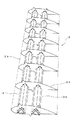
図4は本発明の一実施形態に係る垂直軸型風力発電装置の正面図であり、図1は風車用羽根の骨組み構造を示す斜視図であり、図2は、その翼状板の斜視図である。
Next, an embodiment of a vertical axis wind power generator according to the present invention will be specifically described below.
FIG. 4 is a front view of a vertical axis wind power generator according to an embodiment of the present invention, FIG. 1 is a perspective view showing a framework structure of a blade for a wind turbine, and FIG. 2 is a perspective view of the wing plate. is there.
図4において、垂直軸型風力発電装置1は、垂直に設けた回転軸2と、回転軸2の周方向に複数枚取り付けた羽根3とを備えて成る。
回転軸2の上方には、円板11を介して支持部材12,13が取り付けられている。回転軸2の下方は、軸受21を介して支柱22内に回転自在に支持されている。支柱22は、台座部となるベース23を有する。ベース23は、後述する姿勢安定装置5により基礎に設置される。また、回転軸2の下方には、適宜の変速機構24を介して発電機25が連結されている。
In FIG. 4, the vertical axis
Support
上側支持部材12は、円板11の上側指向折り曲げ部から斜め上方に伸びて羽根3の上方を支持する。下側支持部材13は、円板11の下側指向折り曲げ部から斜め下方に伸びて羽根3の下方を支持する。
The
羽根3は、断面が翼状となっており、一方面3aは流線が長くなる凸状面となっており、他方面3bは流線が短くなるフラット状面となっている。なお、図示のように、一方面3aが外方に面する配置に限らず、一方面3aが軸に向かう内方に面する配置であってもよい。
The
図1において、羽根3は、羽根長手方向の骨材31,32と、この骨材31,32に挿入状態で固定される多数の翼状板33と、この翼状板33の周囲に張られる外形付与板(外皮)34とからなる骨組み構造で形成されている。
In FIG. 1, the
骨材31,32は、三角断面の中空角材で形成されており、例えば図5に示すようなアルミニウム合金の押出材、またはアルミニウム合金板の折り曲げ加工またはアルミニウム合金板の接合構造により製造される。図1では、山形に折り曲げた第1プレートとフラットな第2プレートとを合わせて、リベット接合したものが用いられる。翼状板33の前後に2本の骨材31,32が配設されている。羽根3の大きさに応じて、3本の骨材を配設することもできる。また、前述した支持部材12,13は、この骨材31,32に対して、ボルト締め等で接合される。
The
図2に示すように、翼状板33は、アルミニウム合金板をプレス成形で翼形状の外形に打ち抜いたものである。このプレス成形は、NC機を用いて行われる。そのため、翼状板33の外周は、直線の組み合わせによる曲線近似で形成されている。翼状の型で打ち抜く加工方法もある。
翼状板33は、前述した骨材31,32が挿入される切欠き穴35,36と、後述する外皮34が貫通して位置決めされる突起部37,38と、後述する外皮34が載って安定させる複数の座部39,40が翼状板33に対し90°折り曲げて形成されている。突起部37と二つの座部39とは、翼状板33の凸状面側に配設され、突起部38と三つの座部40とは、翼状板33のフラット状面側に配設されている。
As shown in FIG. 2, the
The wing-
図1に示すように、翼状板33は、所定間隔で骨材31,32に挿入される。そして、骨材31,32と翼状板33との間は複数箇所の溶接で固定される。この両者の固定により、図1のような強固な骨組み構造が形成される。
As shown in FIG. 1, the
外形付与板である外皮34は、アルミニウム合金の薄板であって、翼状板33の周囲に沿って張り付けられる。外皮34は、翼状板33の突起部37,38に貫通されて、翼状板33の座部39,40に載る。なお、図1では、外皮34が張り付けられた後、突起部37,38は、残されたままの状態であるが、外皮34表面に沿って切断されるものであってもよいし、外皮34に沿うように折り曲げられるものであってもよい。また、外皮34は、座部39,40に対して、リベットで固定される。
The
図3は、外皮34の張り付け手順を示す。
〔第1工程〕
図3(a)のように、翼状板33のフラット状面(一方面)の突起38に、外皮34の一端側の穴34aを通して位置決めし、外皮34の他端側を引っ張って、翼状板33に沿わせる。この引っ張りに際しては、外皮34の他端側に張り付けられた延長テーブ部材60を引っ張ることにより行われる。この延長テープ部材60により、外皮34に皺など発生させることなく、均一に引っ張ることができる。
そして、座部40に対して、外皮34をリベット62で固定する。図3(c)のように、リベット62には、ブラインドリベットが用いられ、外皮34の側から、予め設けられた座部40の貫通穴に、ブラインドリベット組立体を挿入し、シャフト63を引き抜くと、ブラインドリベットの下方が膨らみ、シャフト63はちぎれ、図示のようなリベット62による固定状態が形成される。なお、フラット状面側の座部40なお、外皮34の他端側は「へ」の字状に予め外折りされており、一端側とフラットに合わせられるようになっている。
FIG. 3 shows a procedure for attaching the
[First step]
As shown in FIG. 3A, the
Then, the
〔第2工程〕
つぎに、図3(b)のように、翼状板33の凸状面(他方面)側の突起37に、外皮34の他端側の穴34bを通して位置決めし、外皮34の他端側を引っ張って、翼状板33の残り部分に沿わせる。この引っ張りに際しては、外皮34の他端側に張り付けられた延長テーブ部材60を引っ張ることにより行われる。この延長テープ部材60により、外皮34に皺など発生させることなく、均一に引っ張ることができる。そして、外皮34の一端側と他端側との合わせ部分61をスポット溶接にて固定する。
そして、座部39に対して、外皮34をリベット62で固定する。図3(c)のように、リベット62には、ブラインドリベットが用いられ、外皮34の側から、予め設けられた座部39の貫通穴に、ブラインドリベット組立体を挿入し、シャフト63を引き抜くと、ブラインドリベットの下方が膨らみ、シャフト63はちぎれ、図示のようなリベット62による固定状態が形成される。
[Second step]
Next, as shown in FIG. 3 (b), the
Then, the
このような製法で形成される羽根3は、アルミニウム合金製の中空角材の骨材31,32により、強度を保つ構造であり、アルミニウム合金板の翼状板33で形状を保つ構造である。そのため、アルミニウム合金製の薄い外皮34により、羽根3の外形を形成できる。
このように、羽根3は、全体的に軽量で強度があるものに仕上げることができる。その結果、羽根3に作用する風により羽根3は効率的に回転することができる。
The
Thus, the
図4において、羽根3は、最小限の2枚配置であって、その凸状面がそれぞれ外方に向かうように配設されている。風Aに対する羽根3の揚力Bの向きは回転方向斜め外であって、羽根3はC方向に回転する。
なお、羽根3の枚数は、3枚又は4枚であってもよい。また、羽根3は、内周側の複数枚と、外周側の複数枚というように、同心複数円状に配置するものであってもよい。
また、羽根3の凸状面は外周に向けて配置するものに限らず、羽根3のフラット面を外周に向けて配置するものであってもよい。
上述したように、軽量で強度がある羽根3であるため、適宜の枚数で配設された羽根3は風により効率的に回転する。
In FIG. 4, the minimum number of
The number of
Further, the convex surface of the
As described above, since the
次に、本発明の羽根の取付構造について説明する。図6は、羽根の取付構造の断面図である。 Next, the blade mounting structure of the present invention will be described. FIG. 6 is a cross-sectional view of the blade mounting structure.
骨材31、32は、図5、図6に示すように、断面が三角形である押し出し材であり、これらの断面の三角形の一辺が各々、翼弦長と平行に設けられているものである。
取付ブラケット41は、板状部材であり、骨材31、32を嵌合することができるように、略凸型の穴を2つ有している。また、取付ブラケット41の一部が外皮34を回転軸2側に貫通及び突出するように、かつ、その平行面が水平となるように取り付けられている。さらに、取付ブラケット41は、その突出部分に翼弦長(図6の一点鎖線)と平行な辺41aを有しているものである。
支持部材42は、パイプ状部材又は板状部材などである。例えば、パイプ状部材である場合には、細長い楕円状断面であるものを用いて、風の抵抗を抑えるようにしてもよい。
ボルト43は、取付ブラケット41と支持部材42とをボルト接合するものである。図6では、4本で接合しているが、少なくとも2本のボルト43で接合されていればよい。
ピン44は、取付ブラケット41と支持部材42との位置決めをするために、取付ブラケット41と支持部材42とを位置決め接合するものである。図6では、2本のピン44でピン接合しているが、少なくとも1本のピン44でピン接合されていればよい。ただし、より確実に位置決めするために、取付ブラケット41と支持部材42とは、2本以上のピン44によってピン接合されることが好ましい。また、ピンの代わりにリーマボルトや凹凸の嵌合などを利用して位置決め接合を行ってもよい。
As shown in FIGS. 5 and 6, the
The mounting
The
The
The pin 44 positions and joins the mounting
このような羽根の取付構造であれば、取付ブラケット41が、突出部分に翼弦長と平行な辺41aを有しているので、羽根3の翼弦長方向が容易に把握でき、羽根3の取付角度の調整が容易となる。
また、確実に位置決めを行うことができるので、取付角度のずれがなくなり、しかも所望の取付角度を維持することができる。
With such a blade mounting structure, the mounting
In addition, since positioning can be performed reliably, there is no shift in the mounting angle, and a desired mounting angle can be maintained.
なお、骨材31、32の断面の三角形の一辺が各々、翼弦長と平行に設けられているため、羽根3の翼弦長方向が三角形の一辺を基準として把握できるので、取付ブラケット41を使用せずに羽根の取付角度の調整を行うこともできる。
In addition, since one side of the triangle of the cross section of the
なお、本発明は、特許請求の範囲を逸脱しない範囲で設計変更できるものであり、上記実施形態に限定されるものではない。 The present invention can be modified in design without departing from the scope of the claims, and is not limited to the above embodiment.
1 垂直軸型風力発電装置
2 回転軸
3 羽根
5 姿勢安定装置
23 ベース(台座部)
31,32 骨材
33 翼状板
34 外皮(外形付与板)
37,38 突起部
39,40 座部
41 取付ブラケット
43 ボルト
44 ピン
60 延長テープ部材
DESCRIPTION OF
31, 32
37, 38
Claims (9)
多数の翼状板の一方面に対して外形付与板の一端側を位置決めし、外形付与板の一端側を前記翼状板の一方面に固定する第1工程と、外形付与板の他端側を引っ張りながら、多数の翼状板の他方面に対して、外形付与板の他端側を位置決めし、外形付与板の他端側を前記翼状板の他方面に固定する第2工程とを備えて成る羽根の製造方法。 A blade manufacturing method in which a large number of wing-like plates are inserted and fixed to the aggregate in the blade longitudinal direction, and an outer shape imparting plate is attached around the wing-like plate,
A first step of positioning one end side of the outer shape imparting plate with respect to one surface of a large number of wing-shaped plates, and fixing one end side of the outer shape imparting plate to one surface of the winged plate, and pulling the other end side of the outer shape imparting plate However, the blade includes: a second step of positioning the other end of the outer shape imparting plate with respect to the other surface of the plurality of winged plates and fixing the other end of the outer shape imparting plate to the other surface of the winged plate. Manufacturing method.
前記取付ブラケットが、前記突出部分平面上の少なくとも一部に翼弦長と平行な辺を有している請求項7記載の垂直軸型風力発電装置。 The aggregate further includes a plate-like mounting bracket that is attached so that a part of the outer shape imparting plate penetrates and protrudes toward the rotating shaft and the parallel surface is horizontal.
The vertical axis wind power generator according to claim 7, wherein the mounting bracket has a side parallel to a chord length on at least a part of the projecting portion plane.
前記支持部材と前記ブラケットの前記突出部分とを少なくとも2点で接合し、かつ、少なくとも1点で位置決めするための位置決め接合をする請求項8記載の垂直軸型風力発電装置。
A support member provided on the rotating shaft that supports the blade;
The vertical axis wind power generator according to claim 8, wherein the support member and the protruding portion of the bracket are joined at at least two points, and positioning joining is performed for positioning at at least one point.
Priority Applications (18)
| Application Number | Priority Date | Filing Date | Title |
|---|---|---|---|
| JP2003364241A JP4595310B2 (en) | 2003-06-18 | 2003-10-24 | Vertical axis wind power generator |
| CA2752116A CA2752116C (en) | 2003-06-09 | 2004-01-07 | Vertical axis type wind power station |
| EP04700534A EP1640606A4 (en) | 2003-06-09 | 2004-01-07 | Vertial shaft-type wind power generation device and method of producing blade, structure and method of installing blade wheel for wind power generation device, and wind power generation plant for wind protection |
| PCT/JP2004/000034 WO2004109100A1 (en) | 2003-06-09 | 2004-01-07 | Vertial shaft-type wind power generation device and method of producing blade, structure and method of installing blade wheel for wind power generation device, and wind power generation plant for wind protection |
| KR1020057023145A KR20060035609A (en) | 2003-06-09 | 2004-01-07 | Manufacturing method of vertical axis wind turbine and wing, structure and attachment method of windmill of wind turbine and wind turbine |
| CNA2004800160166A CN1802503A (en) | 2003-06-09 | 2004-01-07 | Vertical axis wind power generation device and blade manufacturing method, installation structure and installation method of windmill of wind power generation device, and wind power plant for wind protection |
| RU2005141551/06A RU2005141551A (en) | 2003-06-09 | 2004-01-07 | WIND POWER PLANT OF A VERTICAL-AXIAL TYPE AND METHOD FOR MANUFACTURING BLADES, DESIGN AND METHOD OF INSTALLING A WIND POWER DEVICE FOR A WIND POWER PLANT AND A WIND PROTECTING A WIND POWER |
| EP13163789.4A EP2617992A3 (en) | 2003-06-09 | 2004-01-07 | Vertical axis type wind power station |
| AU2004245778A AU2004245778B2 (en) | 2003-06-09 | 2004-01-07 | Wind power generation device |
| CA2528714A CA2528714C (en) | 2003-06-09 | 2004-01-07 | Vertical axis type wind power station |
| CA2752144A CA2752144C (en) | 2003-06-09 | 2004-01-07 | Vertical axis type wind power station |
| KR1020117003623A KR20110033271A (en) | 2003-06-09 | 2004-01-07 | Vertical Axis Wind Power Unit |
| KR1020117003624A KR101124854B1 (en) | 2003-06-09 | 2004-01-07 | Vertical shaft-type wind power generation device |
| CNA2007101387011A CN101113716A (en) | 2003-06-09 | 2004-01-07 | Vertical axis wind power generation device and blade manufacturing method, installation structure and installation method of windmill of wind power generation device, and wind power plant for wind protection |
| US10/489,307 US7510366B2 (en) | 2003-06-09 | 2004-01-07 | Vertical axis type wind power station |
| TW099135051A TW201107597A (en) | 2003-06-09 | 2004-01-09 | Generator and power supply for use therein |
| TW099135053A TW201104071A (en) | 2003-06-09 | 2004-01-09 | Vertical axis wind turbine generator |
| TW093100579A TW200427923A (en) | 2003-06-09 | 2004-01-09 | Vertical shaft-type wind power generation device and method of producing blade, structure and method of installing blade wheel for wind power generation device, and wind power generation plant for wind protection |
Applications Claiming Priority (2)
| Application Number | Priority Date | Filing Date | Title |
|---|---|---|---|
| JP2003173752 | 2003-06-18 | ||
| JP2003364241A JP4595310B2 (en) | 2003-06-18 | 2003-10-24 | Vertical axis wind power generator |
Publications (2)
| Publication Number | Publication Date |
|---|---|
| JP2005030375A true JP2005030375A (en) | 2005-02-03 |
| JP4595310B2 JP4595310B2 (en) | 2010-12-08 |
Family
ID=34219979
Family Applications (1)
| Application Number | Title | Priority Date | Filing Date |
|---|---|---|---|
| JP2003364241A Expired - Fee Related JP4595310B2 (en) | 2003-06-09 | 2003-10-24 | Vertical axis wind power generator |
Country Status (1)
| Country | Link |
|---|---|
| JP (1) | JP4595310B2 (en) |
Cited By (7)
| Publication number | Priority date | Publication date | Assignee | Title |
|---|---|---|---|---|
| WO2009141922A1 (en) * | 2008-05-23 | 2009-11-26 | 有限会社新宮アトリエ | Windmill device |
| KR100999320B1 (en) * | 2010-04-23 | 2010-12-08 | 손정희 | Lift blades for lift generators and manufacturing methods thereof |
| JP2013519019A (en) * | 2010-02-08 | 2013-05-23 | 国能風力発電有限公司 | Structure of blades for wind wheels of vertical axis wind power generator |
| JP2014101790A (en) * | 2012-11-19 | 2014-06-05 | Wind 19 Inc | Blade for wind power generator and manufacturing method of the same |
| KR101498785B1 (en) * | 2013-05-30 | 2015-03-06 | 군산대학교산학협력단 | Lift-drag hybrid type blade for vertical axis wind power generator and wind power generator with the same |
| JP2016118170A (en) * | 2014-12-22 | 2016-06-30 | 株式会社Cnoパワーソリューションズ | Blade member for blade of vertical shaft type windmill for wind power generation, and blade |
| JP2016156325A (en) * | 2015-02-25 | 2016-09-01 | 株式会社Lixil | Vertical axis windmill |
Citations (5)
| Publication number | Priority date | Publication date | Assignee | Title |
|---|---|---|---|---|
| JPS6292896U (en) * | 1985-12-03 | 1987-06-13 | ||
| JPH028699U (en) * | 1988-06-30 | 1990-01-19 | ||
| JP2000234582A (en) * | 1999-02-16 | 2000-08-29 | Toshiyuki Uchibayashi | Gyro-mill type wind mill |
| JP2003104294A (en) * | 2001-09-27 | 2003-04-09 | Univ Of The Ryukyus | Wing shape |
| JP2003206849A (en) * | 2001-11-08 | 2003-07-25 | Tokai Univ | Straight wing type windmill |
-
2003
- 2003-10-24 JP JP2003364241A patent/JP4595310B2/en not_active Expired - Fee Related
Patent Citations (5)
| Publication number | Priority date | Publication date | Assignee | Title |
|---|---|---|---|---|
| JPS6292896U (en) * | 1985-12-03 | 1987-06-13 | ||
| JPH028699U (en) * | 1988-06-30 | 1990-01-19 | ||
| JP2000234582A (en) * | 1999-02-16 | 2000-08-29 | Toshiyuki Uchibayashi | Gyro-mill type wind mill |
| JP2003104294A (en) * | 2001-09-27 | 2003-04-09 | Univ Of The Ryukyus | Wing shape |
| JP2003206849A (en) * | 2001-11-08 | 2003-07-25 | Tokai Univ | Straight wing type windmill |
Cited By (7)
| Publication number | Priority date | Publication date | Assignee | Title |
|---|---|---|---|---|
| WO2009141922A1 (en) * | 2008-05-23 | 2009-11-26 | 有限会社新宮アトリエ | Windmill device |
| JP2013519019A (en) * | 2010-02-08 | 2013-05-23 | 国能風力発電有限公司 | Structure of blades for wind wheels of vertical axis wind power generator |
| KR100999320B1 (en) * | 2010-04-23 | 2010-12-08 | 손정희 | Lift blades for lift generators and manufacturing methods thereof |
| JP2014101790A (en) * | 2012-11-19 | 2014-06-05 | Wind 19 Inc | Blade for wind power generator and manufacturing method of the same |
| KR101498785B1 (en) * | 2013-05-30 | 2015-03-06 | 군산대학교산학협력단 | Lift-drag hybrid type blade for vertical axis wind power generator and wind power generator with the same |
| JP2016118170A (en) * | 2014-12-22 | 2016-06-30 | 株式会社Cnoパワーソリューションズ | Blade member for blade of vertical shaft type windmill for wind power generation, and blade |
| JP2016156325A (en) * | 2015-02-25 | 2016-09-01 | 株式会社Lixil | Vertical axis windmill |
Also Published As
| Publication number | Publication date |
|---|---|
| JP4595310B2 (en) | 2010-12-08 |
Similar Documents
| Publication | Publication Date | Title |
|---|---|---|
| CA2528714C (en) | Vertical axis type wind power station | |
| JP4514502B2 (en) | Wind turbine for wind power generation | |
| EP2275673B1 (en) | Manufacturing WTG blade having a spar | |
| EP1746286A1 (en) | Support arm installation structure for vertical axis wind wheel, and vertical axis wind wheel | |
| US9228564B2 (en) | Integrated wind turbine | |
| JP2009156260A (en) | Forward tilt tower top section | |
| JP4595310B2 (en) | Vertical axis wind power generator | |
| US20180142669A1 (en) | Spiral blade unit and wind generator and blade connector for the unit | |
| JP2019210912A (en) | Vertical shaft windmill and wind power generator | |
| JP2004204801A (en) | Wind receiving blade for windmill | |
| KR100999320B1 (en) | Lift blades for lift generators and manufacturing methods thereof | |
| JP2008101536A (en) | Blade for wind power generator | |
| TW201000752A (en) | Wind driven power generator | |
| KR101888838B1 (en) | Intergrating structure of wind turbine using diffusion tube | |
| JP2016118170A (en) | Blade member for blade of vertical shaft type windmill for wind power generation, and blade | |
| JP2007046559A (en) | Blade for wind power generator | |
| JP2008520894A (en) | Vertical axis turbine equipment | |
| JP2005291185A (en) | Wind power generator | |
| JP2022051055A (en) | Vertical axis wind turbine and vertical axis wind power generator | |
| JP2019183715A (en) | Vertical shaft type wind power generator | |
| WO2019054307A1 (en) | Horizontal-shaft windmill | |
| KR101555510B1 (en) | Horizontal axis wind turbine having extruding blade | |
| WO2011094915A1 (en) | Supporting rod structure of wind wheel in vertical axis wind power generator | |
| JP2002266748A (en) | Windmill | |
| KR20250032655A (en) | Small vertical wind turbine with manual pitch regulator |
Legal Events
| Date | Code | Title | Description |
|---|---|---|---|
| A621 | Written request for application examination |
Free format text: JAPANESE INTERMEDIATE CODE: A621 Effective date: 20061017 |
|
| A131 | Notification of reasons for refusal |
Free format text: JAPANESE INTERMEDIATE CODE: A131 Effective date: 20100302 |
|
| A521 | Written amendment |
Free format text: JAPANESE INTERMEDIATE CODE: A523 Effective date: 20100506 |
|
| A131 | Notification of reasons for refusal |
Free format text: JAPANESE INTERMEDIATE CODE: A131 Effective date: 20100601 |
|
| A521 | Written amendment |
Free format text: JAPANESE INTERMEDIATE CODE: A523 Effective date: 20100729 |
|
| TRDD | Decision of grant or rejection written | ||
| A01 | Written decision to grant a patent or to grant a registration (utility model) |
Free format text: JAPANESE INTERMEDIATE CODE: A01 Effective date: 20100824 |
|
| A01 | Written decision to grant a patent or to grant a registration (utility model) |
Free format text: JAPANESE INTERMEDIATE CODE: A01 |
|
| A61 | First payment of annual fees (during grant procedure) |
Free format text: JAPANESE INTERMEDIATE CODE: A61 Effective date: 20100906 |
|
| R150 | Certificate of patent or registration of utility model |
Ref document number: 4595310 Country of ref document: JP Free format text: JAPANESE INTERMEDIATE CODE: R150 Free format text: JAPANESE INTERMEDIATE CODE: R150 |
|
| FPAY | Renewal fee payment (event date is renewal date of database) |
Free format text: PAYMENT UNTIL: 20131001 Year of fee payment: 3 |
|
| R250 | Receipt of annual fees |
Free format text: JAPANESE INTERMEDIATE CODE: R250 |
|
| R250 | Receipt of annual fees |
Free format text: JAPANESE INTERMEDIATE CODE: R250 |
|
| LAPS | Cancellation because of no payment of annual fees |