JP2005020692A - Data receiving method and apparatus, and data transmission system - Google Patents
Data receiving method and apparatus, and data transmission system Download PDFInfo
- Publication number
- JP2005020692A JP2005020692A JP2003373518A JP2003373518A JP2005020692A JP 2005020692 A JP2005020692 A JP 2005020692A JP 2003373518 A JP2003373518 A JP 2003373518A JP 2003373518 A JP2003373518 A JP 2003373518A JP 2005020692 A JP2005020692 A JP 2005020692A
- Authority
- JP
- Japan
- Prior art keywords
- signal
- data
- value
- level
- unit
- Prior art date
- Legal status (The legal status is an assumption and is not a legal conclusion. Google has not performed a legal analysis and makes no representation as to the accuracy of the status listed.)
- Pending
Links
Images


Classifications
-
- E—FIXED CONSTRUCTIONS
- E04—BUILDING
- E04H—BUILDINGS OR LIKE STRUCTURES FOR PARTICULAR PURPOSES; SWIMMING OR SPLASH BATHS OR POOLS; MASTS; FENCING; TENTS OR CANOPIES, IN GENERAL
- E04H12/00—Towers; Masts or poles; Chimney stacks; Water-towers; Methods of erecting such structures
- E04H12/02—Structures made of specified materials
- E04H12/08—Structures made of specified materials of metal
- E04H12/10—Truss-like structures
-
- H—ELECTRICITY
- H04—ELECTRIC COMMUNICATION TECHNIQUE
- H04L—TRANSMISSION OF DIGITAL INFORMATION, e.g. TELEGRAPHIC COMMUNICATION
- H04L25/00—Baseband systems
- H04L25/02—Details ; arrangements for supplying electrical power along data transmission lines
- H04L25/06—DC level restoring means; Bias distortion correction ; Decision circuits providing symbol by symbol detection
- H04L25/061—DC level restoring means; Bias distortion correction ; Decision circuits providing symbol by symbol detection providing hard decisions only; arrangements for tracking or suppressing unwanted low frequency components, e.g. removal of DC offset
- H04L25/063—Setting decision thresholds using feedback techniques only
-
- B—PERFORMING OPERATIONS; TRANSPORTING
- B66—HOISTING; LIFTING; HAULING
- B66C—CRANES; LOAD-ENGAGING ELEMENTS OR DEVICES FOR CRANES, CAPSTANS, WINCHES, OR TACKLES
- B66C23/00—Cranes comprising essentially a beam, boom, or triangular structure acting as a cantilever and mounted for translatory of swinging movements in vertical or horizontal planes or a combination of such movements, e.g. jib-cranes, derricks, tower cranes
- B66C23/62—Constructional features or details
-
- H—ELECTRICITY
- H04—ELECTRIC COMMUNICATION TECHNIQUE
- H04L—TRANSMISSION OF DIGITAL INFORMATION, e.g. TELEGRAPHIC COMMUNICATION
- H04L25/00—Baseband systems
- H04L25/02—Details ; arrangements for supplying electrical power along data transmission lines
- H04L25/06—DC level restoring means; Bias distortion correction ; Decision circuits providing symbol by symbol detection
- H04L25/061—DC level restoring means; Bias distortion correction ; Decision circuits providing symbol by symbol detection providing hard decisions only; arrangements for tracking or suppressing unwanted low frequency components, e.g. removal of DC offset
- H04L25/066—Multilevel decisions, not including self-organising maps
Landscapes
- Engineering & Computer Science (AREA)
- Signal Processing (AREA)
- Computer Networks & Wireless Communication (AREA)
- Power Engineering (AREA)
- Architecture (AREA)
- Wood Science & Technology (AREA)
- Materials Engineering (AREA)
- Civil Engineering (AREA)
- Structural Engineering (AREA)
- Chemical & Material Sciences (AREA)
- Life Sciences & Earth Sciences (AREA)
- Mechanical Engineering (AREA)
- Dc Digital Transmission (AREA)
- Synchronisation In Digital Transmission Systems (AREA)
- Communication Control (AREA)
Abstract
【課題】 データ通信の初期化において、信号レベルの判定レベルを適切に設定し、その設定を小さな回路規模の構成で実現するデータ受信方法およびその装置、並びにデータ伝送システムを提供する。
【解決手段】 比較回路574は、差分値ddとその差分値ddに応じた理想値とを比較する。比較回路574は、差分値ddが理想値より大きい場合、当該理想値に所定の数値を加算して、現在選択されているレジスタ576a〜576nを更新する。また、比較回路574は、差分値ddが理想値より小さい場合、当該理想値から所定の数値を減算して、現在選択されているレジスタ576a〜576nを更新する。判定レベル値演算回路572は、レジスタ576a〜576nに設定された理想値を用いて、判定レベルR1〜R13を演算し、それぞれ判定レベル記憶部573が有するレジスタ577a〜577mに記憶させる。
【選択図】 図12
PROBLEM TO BE SOLVED: To provide a data receiving method and apparatus, and a data transmission system for appropriately setting a signal level judgment level in initialization of data communication and realizing the setting with a small circuit scale configuration.
A comparison circuit 574 compares a difference value dd with an ideal value corresponding to the difference value dd. When the difference value dd is larger than the ideal value, the comparison circuit 574 adds a predetermined numerical value to the ideal value, and updates the currently selected registers 576a to 576n. In addition, when the difference value dd is smaller than the ideal value, the comparison circuit 574 subtracts a predetermined numerical value from the ideal value, and updates the currently selected registers 576a to 576n. The determination level value calculation circuit 572 calculates the determination levels R1 to R13 using the ideal values set in the registers 576a to 576n, and stores them in the registers 577a to 577m of the determination level storage unit 573, respectively.
[Selection] FIG.
Description
本発明は、データ受信方法およびその装置、並びにデータ伝送システムに関し、より特定的には、リング型等で各装置を伝送路によって接続し、互いに判定レベルを設定して一方向の電気通信を行うデータ受信方法およびその装置、並びにデータ伝送システムに関する。 The present invention relates to a data receiving method, an apparatus therefor, and a data transmission system, and more specifically, each apparatus is connected by a transmission line in a ring type or the like, and a determination level is set to each other to perform one-way electrical communication. The present invention relates to a data receiving method and apparatus, and a data transmission system.
近年、カーナビゲーションやITS(Intelligent Transport Systems)といったインターネットや画像情報を自動車内等の空間において伝送する場合、大容量かつ高速な通信が要求される。このようなデジタル化した映像や音声データ、あるいはコンピュータデータ等のデジタルデータを伝送するための通信方式の検討が盛んに行われ、自動車内等の空間においてもデジタルデータを伝送するネットワークの導入が本格化してきている。この車内ネットワークは、例えば、物理的なトポロジをリング・トポロジとし、複数のノードをリング・トポロジで接続させることによって一方向のリング型LANを形成し、オーディオ機器、ナビゲーション機器、あるいは情報端末機器等対して統合化した接続を目指している。上記リング型LANで用いられる情報系の通信プロトコルとしては、例えば、Media Oriented Systems Transport(以下、MOSTと記載する)がある。このMOSTでは、通信プロトコルだけでなく、分散システムの構築方法まで言及しており、MOSTネットワークのデータは、フレームを基本単位として伝送され、各ノードを次々にフレームが一方向に伝送される。 2. Description of the Related Art In recent years, when the Internet and image information such as car navigation and ITS (Intelligent Transport Systems) are transmitted in a space such as an automobile, large-capacity and high-speed communication is required. Communication systems for transmitting digital data such as digitized video and audio data, or computer data are being actively studied, and a network that transmits digital data even in spaces such as automobiles has been fully introduced. It is becoming. In this in-vehicle network, for example, a physical topology is a ring topology, and a plurality of nodes are connected by a ring topology to form a unidirectional ring LAN, and audio equipment, navigation equipment, information terminal equipment, etc. It aims at an integrated connection. As an information communication protocol used in the ring LAN, there is, for example, Media Oriented Systems Transport (hereinafter referred to as MOST). In this MOST, not only a communication protocol but also a method for constructing a distributed system is mentioned, and data of the MOST network is transmitted with a frame as a basic unit, and the frame is transmitted in one direction to each node one after another.
ところで、車内等に設けられるリング型LANの場合、放射ノイズが自動車等に搭載された他の電子機器に対する誤動作の原因になることがあり、また、他の機器からの放射ノイズの影響を受けることなく正確に伝送する必要もある。このため、従来のMOSTを用いたリング型LANでは、各ノードを光ファイバーケーブルで接続することによって、電磁波の発生を防止しながら耐ノイズ性を向上させている。また、ツイストペア線や同軸ケーブルのような安価なケーブルを用いた電気通信を行い、放射ノイズが少なく耐ノイズ性を向上しながら20Mbpsを超えるような高速なデータ伝送を可能にしているものもある。例えば、上記電気通信において伝送される信号は、デジタル信号をシンボルタイミング毎に8個の信号レベルにマッピングして、伝送路に送出される(例えば特許文献1参照。)。 By the way, in the case of a ring-type LAN provided in a car or the like, radiation noise may cause malfunction of other electronic devices mounted on the car or the like, and may be affected by radiation noise from other devices. There is also a need for accurate transmission. For this reason, in a conventional ring LAN using MOST, each node is connected by an optical fiber cable to improve noise resistance while preventing generation of electromagnetic waves. In addition, there are some that perform electrical communication using an inexpensive cable such as a twisted pair cable or a coaxial cable, and enable high-speed data transmission exceeding 20 Mbps while reducing noise and improving noise resistance. For example, a signal transmitted in the telecommunications is transmitted to a transmission line after mapping a digital signal to eight signal levels for each symbol timing (see, for example, Patent Document 1).
図15〜図18を参照して、特許文献1で開示されたデータ受信装置について説明する。なお、図15は当該データ受信装置の構成を示すブロック図であり、図16は当該データ受信装置の判定レベルを説明するための図であり、図17は図15の判定レベル設定部107の内部構成を示すブロック図であり、図18は当該データ受信装置の判定レベル設定方法を説明するための図である。
With reference to FIGS. 15 to 18, the data receiving device disclosed in
図15において、データ受信装置は、レシーバ101、ローパスフィルタ102、A/Dコンバータ103、デジタルフィルタ104、判定処理部105、同期検出部106、判定レベル設定部107、および判定レベル設定開始検出部108を有している。レシーバ101は、例えばデジタル信号がシンボルタイミング毎に8個の信号レベルにマッピングされた電気信号Drを他の装置から受信する。ローパスフィルタ102は、レシーバ101が受信した電気信号Drの信号帯域以外の雑音を除去して、電気信号DrをA/Dコンバータ103に送る。A/Dコンバータ103は、電気信号Drをデジタル信号に変換して、デジタルフィルタ104および同期検出部106に送る。デジタルフィルタ104は、A/Dコンバータ103から出力されたデジタル信号が有するシンボルレートの2分の1周波数帯域を帯域通過させ、判定処理部105へ出力する。同期検出部106は、A/Dコンバータ103から出力されたデジタル信号の同期を検出する。判定レベル設定部107は、デジタルフィルタ104から出力された信号に対して、その信号レベルを閾値判定するための判定レベルを設定する。判定レベル設定開始検出部108は、他の装置から伝送された判定レベル設定開始パターン信号を検出する。そして、判定処理部105は、判定レベル設定部107で設定された判定レベルに基づいて、デジタルフィルタ104から出力された信号が有するデータシンボルを復号する。
15, the data receiving apparatus includes a
電気信号Drは、データ送信装置(図示せず)において8種類のデータシンボルを8個の信号レベルにマッピングされている。例えば、電気信号Drは、上記データシンボルを「+7」、「+5」、「+3」、「+1」、「−1」、「−3」、「−5」、および「−7」の8個の信号レベルのいずれかにマッピングするように定められている(図16参照)。このような電気信号Drが有する各信号レベルを判定するために、上記データ受信装置では、データ伝送を行う前に判定レベル設定が行われる。この判定レベル設定処理の際、上記データ送信装置から初期化パターン信号(以下、トレーニング信号TSと記載する)が送信される。トレーニング信号TSは、受信側で同期確立するための同期パターン信号と、判定レベル設定開始パターン信号(例えば、最大の振幅レベルを所定期間継続する)と、データ送信装置およびデータ受信装置で予め定められたデータパターンの判定レベル設定パターン信号とを含んでいる。判定レベル設定パターン信号は、上記全ての信号レベルが含まれ、様々なパターンが現れるPNパターン信号等が用いられる。上記データ送信装置は、電源投入時等にトレーニング信号TSを出力する。 In the electrical signal Dr, eight types of data symbols are mapped to eight signal levels in a data transmission device (not shown). For example, the electrical signal Dr includes eight data symbols “+7”, “+5”, “+3”, “+1”, “−1”, “−3”, “−5”, and “−7”. Is mapped to any one of the signal levels (see FIG. 16). In order to determine each signal level of such an electric signal Dr, the data receiving apparatus sets a determination level before performing data transmission. During the determination level setting process, an initialization pattern signal (hereinafter referred to as a training signal TS) is transmitted from the data transmission device. The training signal TS is determined in advance by a synchronization pattern signal for establishing synchronization on the receiving side, a determination level setting start pattern signal (for example, a maximum amplitude level is continued for a predetermined period), a data transmission device, and a data reception device. Data pattern determination level setting pattern signal. The determination level setting pattern signal includes all the above signal levels, and a PN pattern signal or the like in which various patterns appear. The data transmission device outputs a training signal TS when the power is turned on.
データ受信装置は、トレーニング信号TSが有する上記同期パターン信号を受信すると、同期検出部106でクロック再生を行い、同期が確立されたことを検出する。その後、上記判定レベル設定開始パターン信号を判定レベル設定開始検出部108によって検出し、上記トレーニング信号TSを受信すると判定レベル設定部107にて判定レベルの設定を行う。
When the data reception device receives the synchronization pattern signal included in the training signal TS, the
判定レベル設定部107は、上記各信号レベルをP7、P5、P3、P1、M1、M3、M5、およびM7として取り扱う。そして、判定レベル設定部107は、上記各信号レベル間のそれぞれの判定レベルP57、P35、P13、PM1、M13、M35、およびM57を設定する(図16参照)。
The determination
図17において、判定レベル設定部107は、最大最小信号レベル記憶部110と、判定レベル値演算回路130と、判定レベル記憶部140と、比較回路151および152と、セレクタ161および162とを有している。最大最小信号レベル記憶部110は、上記各信号レベルの最大値および最小値をそれぞれ保持するレジスタ111〜126を有している。各信号レベルの最大値を保持したレジスタは、セレクタ161と接続され、各信号レベルの最小値を保持したレジスタは、セレクタ162と接続されている。トレーニング信号TSは、比較回路151および152に入力する。そして、セレクタ161および162は、そのトレーニング信号TSと同期した教師信号MSに基づいて、現在入力しているトレーニング信号TSの信号レベルに相当する最大最小信号レベル記憶部110に保持された最大値および最小値を、それぞれ比較回路151および152に出力する。比較回路151は、現在入力しているトレーニング信号TSの信号レベルと、それに相当する最大最小信号レベル記憶部110に保持された最大値とを比較する。そして、比較回路151は、トレーニング信号TSの信号レベルが上記最大値を超える場合、その信号レベルの最大値を保持する最大最小信号レベル記憶部110のレジスタを、その信号レベルに更新する。比較回路152は、現在入力しているトレーニング信号TSの信号レベルと、それに相当する最大最小信号レベル記憶部110に保持された最小値とを比較する。そして、比較回路152は、トレーニング信号TSの信号レベルが上記最小値より小さい場合、その信号レベルの最小値を保持する最大最小信号レベル記憶部110のレジスタを、その信号レベルに更新する。
In FIG. 17, the determination
このような更新が繰り返されることによって、最大最小信号レベル記憶部110には、トレーニング信号TSの各信号レベルにおけるそれぞれの最大値および最小値が保持される。判定レベル値演算回路130は、最大最小信号レベル記憶部110に保持された各信号レベルにおけるそれぞれの最大値および最小値を用いて、隣接する信号レベルに対する判定レベルをそれぞれ演算して、判定レベル記憶部140に出力する。具体的には、判定レベル値演算回路130は、隣接する信号レベルに対する判定レベルを、値が大きな信号レベルの最小値と値が小さな信号レベルの最大値とを平均して演算する。例えば、判定レベル値演算回路130は、図18に示すように、信号レベルP7の最小値P7minと信号レベルP5の最大値P5maxとを平均して、判定レベルP57を演算する。判定レベル記憶部140は、上記判定レベルをそれぞれ保持するレジスタ141〜147を有している。
しかしながら、上記データ送信装置から送信されるトレーニング信号TSには、突発的なノイズが加わったり急激なレベル変動が生じたりする場合がある。そして、これらの急峻な変動によって上述したトレーニング信号TSの各信号レベルの最大値や最小値が変化した場合、それらの最大値および最小値が最大最小信号レベル記憶部110に保持されてしまう。そして、図18に示すように、判定レベルP57の演算では、信号レベルP7の最小値P7minおよび信号レベルP5の最大値P5maxのみが用いられ、他の信号レベルP7およびP5の値は用いられない。したがって、上記判定レベルは、急峻な変動によって保持された最大値および最小値に基づいて設定されることになり、この状況で設定された判定レベルでは、その後のデータ受信において正確な信号レベルの判定が困難となった。
However, the training signal TS transmitted from the data transmission device may be suddenly added with noise or suddenly change in level. When the maximum value or the minimum value of each signal level of the training signal TS described above changes due to these steep fluctuations, the maximum value and the minimum value are held in the maximum / minimum signal
また、判定レベル設定部107が有するレジスタや比較回路は、各信号レベルと、その最大値および最小値それぞれに対応して比較/保持するため、回路規模が大きくなり、データ受信装置のコスト増加の要因となっていた。
In addition, since the register and the comparison circuit included in the determination
それ故に、本発明の目的は、データ通信の初期化において、信号レベルの判定レベルを適切に設定し、その設定を小さな回路規模の構成で実現するデータ受信方法およびその装置、並びにデータ伝送システムを提供することである。 Therefore, an object of the present invention is to provide a data reception method and apparatus, and a data transmission system that appropriately set a signal level determination level in initialization of data communication and realize the setting with a small circuit scale configuration. Is to provide.
上記目的を達成するために、本発明は、以下に述べるような特徴を有している。なお、括弧内の参照符号等は、本発明の理解を助けるために、後述する実施の形態との対応関係を示したものであって、本発明の範囲を何ら限定するものではない。 In order to achieve the above object, the present invention has the following features. In addition, in order to assist the understanding of the present invention, reference numerals and the like in parentheses indicate a correspondence relationship with embodiments to be described later, and do not limit the scope of the present invention.
本発明のデータ受信方法は、送信データの各シンボルを複数の信号レベル(+7、+5、+3、+1、−1、−3、−5、−7)のいずれかにマッピングして送信された伝送信号を受信するため方法であって、初期動作の際、伝送信号の複数の信号レベルが既知の変動パターン(PNデータに基づく信号)で送信されたトレーニングパターンから、シンボルに応じて信号レベルを検出し、受信する複数の信号レベルの理想値(P1〜P14の理想値)を所定の条件に基づいて初期設定してそれぞれ保持し、トレーニングパターンのシンボルに応じて、新たに検出した信号レベルと既に保持している理想値とを比較し、その大小関係に基づいて既に保持している理想値を所定量増減して新たな理想値にそれぞれ更新することを繰り返し、トレーニングパターンのシンボルに応じてそれぞれ更新された理想値を用いて、データ受信の際にデータ送信される伝送信号の複数の信号レベルをそれぞれ区別して判定するための判定レベル(R1〜R13)をそれぞれ設定する。 In the data reception method of the present invention, transmission is performed by mapping each symbol of transmission data to one of a plurality of signal levels (+7, +5, +3, +1, -1, -3, -5, -7). A method for receiving a signal, which detects a signal level according to a symbol from a training pattern in which a plurality of signal levels of a transmission signal are transmitted in a known variation pattern (a signal based on PN data) during initial operation. Then, the ideal values (ideal values of P1 to P14) of the plurality of signal levels to be received are initially set based on a predetermined condition and held respectively, and the newly detected signal level and the already detected signal level are already determined according to the training pattern symbols. Compared with the held ideal value, the ideal value already held is increased or decreased by a predetermined amount based on the magnitude relationship, and updated to a new ideal value, respectively. Determination levels (R1 to R13) for distinguishing and determining a plurality of signal levels of transmission signals transmitted at the time of data reception using ideal values respectively updated according to symbols of the scanning pattern Set.
一例として、所定の条件に基づいて初期設定して保持する理想値は、トレーニングパターンのシンボルに応じて検出したそれぞれの最初の信号レベルである。他の例として、所定の条件に基づいて初期設定して保持する理想値は、それぞれ予め設定された固定値である。 As an example, the ideal value that is initially set and held based on a predetermined condition is each initial signal level detected according to the symbol of the training pattern. As another example, ideal values that are initially set and held based on predetermined conditions are fixed values that are set in advance.
判定レベルは、トレーニングパターンのシンボルに応じてそれぞれ更新された理想値のうち、隣接する理想値をそれぞれ平均することにより設定されてもかまわない。 The determination level may be set by averaging adjacent ideal values among the ideal values respectively updated according to the symbols of the training pattern.
一例として、トレーニングパターンのシンボルに応じて、新たに検出した信号レベルと既に保持している理想値とを比較し、新たに検出した信号レベルが既に保持している理想値より大きいときには、既に保持している理想値を一定量加算して新たな理想値に更新し、新たに検出した信号レベルが既に保持している理想値より小さいときには、既に保持している理想値から一定量減算して新たな理想値に更新する。さらに、加算または減算する一定量(0.25階調)を、常に比較したレベル差(1.00階調)以下になるように設定してもかまわない。 As an example, the newly detected signal level is compared with the ideal value already held according to the symbol of the training pattern, and if the newly detected signal level is greater than the ideal value already held, it is already held. Is updated to a new ideal value by adding a certain amount, and when the newly detected signal level is smaller than the ideal value already held, a certain amount is subtracted from the already held ideal value. Update to a new ideal value. Furthermore, a certain amount (0.25 gradation) to be added or subtracted may be set so as to be always equal to or less than the compared level difference (1.00 gradation).
他の例として、トレーニングパターンのシンボルに応じて、新たに検出した信号レベルと既に保持している理想値とを比較し、新たに検出した信号レベルが既に保持している理想値より大きい場合には、既に保持している理想値にそのレベル差以下で、かつそのレベル差に応じて重み付けした量を加算した新たな理想値に更新し、新たに検出した信号レベルが既に保持している理想値より小さい場合には、既に保持している理想値からそのレベル差以下で、かつそのレベル差に応じて重み付けした量を減算して新たな理想値に更新する。 As another example, the newly detected signal level is compared with the ideal value already held according to the symbol of the training pattern, and the newly detected signal level is greater than the ideal value already held. Is updated to a new ideal value that is equal to or less than the level difference of the already held ideal value and added with an amount weighted according to the level difference, and the newly detected signal level is already held. When the value is smaller than the value, an amount that is equal to or smaller than the level difference and weighted according to the level difference is subtracted from the already held ideal value to be updated to a new ideal value.
また、トレーニングパターンにおけるシンボルに応じた複数の信号レベルを、そのシンボル(B(k))に対する直前のシンボル(B(k−1))の信号レベルとの差分(dd)によって検出し、判定レベルは、データ受信の際にマッピングされてデータ送信される伝送信号におけるシンボルに応じた複数の信号レベルを、それぞれそのシンボルに対する直前のシンボルの信号レベルとの差分によって区別して判定するために設定してもかまわない。 In addition, a plurality of signal levels corresponding to the symbols in the training pattern are detected by the difference (dd) between the signal level of the immediately preceding symbol (B (k−1)) with respect to the symbol (B (k)), and the determination level Is set in order to distinguish and determine a plurality of signal levels corresponding to symbols in a transmission signal mapped and transmitted at the time of data reception based on the difference from the signal level of the immediately preceding symbol for that symbol. It doesn't matter.
さらに、初期動作終了後に、判定レベルを用いて伝送信号におけるシンボルに応じた複数の信号レベルを区別した結果を出力してもよい。具体的には、送受信するデータが、MOST(Media Oriented Systems Transport)で定義されたデータフォーマットの信号である。 Furthermore, after the completion of the initial operation, the determination level may be used to output a result of distinguishing a plurality of signal levels corresponding to symbols in the transmission signal. Specifically, data to be transmitted / received is a signal having a data format defined by MOST (Media Oriented Systems Transport).
例えば、上記トレーニングパターンは、送信側との同期を確立するためのクロック成分を含むロック信号が送信された後に所定のヘッダが付与されて送信され、複数の信号レベルは、相対的に信号レベルが高い上位群と相対的に信号レベルが低い下位群とを含んでおり、トレーニングパターンおよびロック信号は、上位群から選ばれた信号レベルと下位群から選ばれた信号レベルとが交互になるようにマッピングされており、ヘッダは、シンボルが同じ信号レベルにマッピングされている。この場合、初期動作の際、さらに、ロック信号に含まれるクロック成分を再生して送信側との同期を確立し、同期が確立されたクロック毎の信号レベルの内、隣接する信号レベルが同じであるとき、ヘッダを検出してもかまわない。また、トレーニングパターンは、ヘッダの送出から所定の時間送信され、理想値をそれぞれ更新する繰り返しは、ヘッダの受信から所定の時間を経過することによって終了してもよい。 For example, the training pattern is transmitted with a predetermined header after a lock signal including a clock component for establishing synchronization with the transmission side is transmitted, and a plurality of signal levels are relatively signal levels. It includes a high group and a low group with a relatively low signal level, so that the training pattern and lock signal alternate between the signal level selected from the high group and the signal level selected from the low group. In the header, symbols are mapped to the same signal level. In this case, during the initial operation, the clock component included in the lock signal is further reproduced to establish synchronization with the transmission side, and the adjacent signal levels are the same among the signal levels for each clock for which synchronization has been established. In some cases, the header may be detected. Further, the training pattern is transmitted for a predetermined time from the transmission of the header, and the repetition of updating the ideal values may be terminated when a predetermined time elapses from the reception of the header.
本発明のデータ伝送装置(1)は、他のデータ伝送装置(1)と伝送路(80)を介して接続され、送信データの各シンボルを複数の信号レベルのいずれかにマッピングして送信された伝送信号を受信するための装置であって、初期動作の際に、データ伝送装置から送信された伝送信号の複数の信号レベルが既知の変動パターンで形成されたトレーニングパターンから、シンボルに応じて信号レベルを検出する信号レベル検出部(54)と、受信する複数の信号レベルの理想値を所定の条件に基づいて初期設定してそれぞれ記憶した後、所定の処理に基づいてその理想値が更新される複数の記憶手段(576)を有する理想値記憶部(571)と、トレーニングパターンのシンボルに応じて、信号レベル検出部が新たに検出した信号レベルと既に記憶手段が記憶している理想値とを比較し、その大小関係に基づいてその記憶手段が記憶している理想値を所定量増減して新たな理想値にそれぞれその記憶手段の値を更新することを繰り返す比較更新部(574)と、複数の記憶手段がそれぞれ更新されて記憶している理想値を用いて、データ受信の際にデータ伝送装置からデータ送信される伝送信号の複数の信号レベルをそれぞれ区別して判定するための判定レベルをそれぞれ演算する判定レベル値演算部(572)と、判定レベル値演算部が演算した判定レベルをそれぞれ記憶する判定レベル記憶部(573)とを備える。 The data transmission device (1) of the present invention is connected to another data transmission device (1) via a transmission line (80), and is transmitted by mapping each symbol of transmission data to one of a plurality of signal levels. In response to a symbol, a training pattern in which a plurality of signal levels of a transmission signal transmitted from a data transmission device are formed in a known variation pattern in an initial operation. A signal level detection unit (54) for detecting a signal level and ideal values of a plurality of received signal levels are initialized and stored based on a predetermined condition, and then the ideal value is updated based on a predetermined process. An ideal value storage unit (571) having a plurality of storage means (576) and a signal level newly detected by the signal level detection unit according to the symbol of the training pattern The ideal value stored in the storage means is compared with the ideal value stored in the storage means, and the ideal value stored in the storage means is increased or decreased by a predetermined amount based on the magnitude relationship, and the value of the storage means is updated to a new ideal value, respectively. And a plurality of transmission signals transmitted from the data transmission apparatus during data reception using the comparison / update unit (574) that repeats the operation and the ideal values that are respectively updated and stored in the plurality of storage units. A determination level value calculation unit (572) that calculates a determination level for distinguishing and determining each level, and a determination level storage unit (573) that stores the determination level calculated by the determination level value calculation unit, respectively.
一例として、理想値記憶部が有する複数の記憶手段に所定の条件に基づいて初期設定してそれぞれ記憶される理想値は、信号レベル検出部がトレーニングパターンのシンボルに応じて検出した最初の信号レベルである。他の例として、理想値記憶部が有する複数の記憶手段に所定の条件に基づいて初期設定してそれぞれ記憶される理想値は、予め設定された固定値である。 As an example, the ideal values initially set and stored in a plurality of storage means included in the ideal value storage unit based on predetermined conditions are the first signal levels detected by the signal level detection unit according to the symbols of the training pattern It is. As another example, the ideal values initially set and stored in a plurality of storage units included in the ideal value storage unit based on predetermined conditions are fixed values set in advance.
判定レベル値演算部は、複数の記憶手段がそれぞれ更新されて記憶している理想値のうち隣接する理想値をそれぞれ平均することによって判定レベルを演算してもかまわない。 The determination level value calculation unit may calculate the determination level by averaging adjacent ideal values among the ideal values that are updated and stored in the plurality of storage units.
一例として、比較更新部は、トレーニングパターンのシンボルに応じて、信号レベル検出部が新たに検出した信号レベルが既に記憶手段が記憶している理想値より大きい場合には、既にその記憶手段が記憶している理想値を一定量加算して新たな理想値にその記憶手段の値を更新し、信号レベル検出部が新たに検出した信号レベルが既に記憶手段が記憶している理想値より小さい場合には、既にその記憶手段が記憶している理想値から一定量減算して新たな理想値にその記憶手段の値を更新する。さらに、比較更新部は、常に比較したレベル差以下になるように設定した一定量で、既に記憶手段が記憶している理想値を加算または減算してもかまわない。 As an example, if the signal level newly detected by the signal level detection unit is greater than the ideal value already stored in the storage unit according to the symbol of the training pattern, the comparison update unit already stores the storage unit. When a certain amount of the ideal value is added and the value of the storage means is updated to a new ideal value, and the signal level newly detected by the signal level detection unit is smaller than the ideal value already stored in the storage means In this case, a certain amount is subtracted from the ideal value already stored in the storage means, and the value of the storage means is updated to a new ideal value. Further, the comparison / update unit may add or subtract the ideal value already stored in the storage unit by a fixed amount that is always set to be equal to or smaller than the compared level difference.
他の例として、比較更新部は、トレーニングパターンのシンボルに応じて、信号レベル検出部が新たに検出した信号レベルが既に記憶手段が記憶している理想値より大きい場合には、既にその記憶手段が記憶している理想値にそのレベル差以下で、かつそのレベル差に応じて重み付けした量を加算して新たな理想値にその記憶手段の値を更新し、信号レベル検出部が新たに検出した信号レベルが既に記憶手段が記憶している理想値より小さい場合には、既にその記憶手段が記憶している理想値からそのレベル差以下で、かつそのレベル差に応じて重み付けした量を減算して新たな理想値にその記憶手段の値を更新する。 As another example, if the signal level newly detected by the signal level detection unit is greater than the ideal value already stored in the storage unit according to the symbol of the training pattern, the comparison / update unit already stores the storage unit. Is added to the ideal value that is stored below the level difference and weighted according to the level difference to update the value of the storage means to the new ideal value, and the signal level detector newly detects If the signal level is smaller than the ideal value already stored in the storage means, the amount weighted according to the level difference is subtracted from the ideal value already stored in the storage means. Then, the value of the storage means is updated to a new ideal value.
信号レベル検出部は、トレーニングパターンにおけるシンボルに応じた複数の信号レベルを、そのシンボルに対する直前のシンボルの信号レベルとの差分によって検出し、判定レベルは、データ受信の際にマッピングされてデータ伝送装置からデータ送信される伝送信号におけるシンボルに応じた複数の信号レベルをそれぞれそのシンボルに対する直前のシンボルの信号レベルとの差分によって区別して判定するために設定してもかまわない。 The signal level detection unit detects a plurality of signal levels corresponding to the symbol in the training pattern based on a difference from the signal level of the immediately preceding symbol with respect to the symbol, and the determination level is mapped at the time of data reception to be a data transmission device A plurality of signal levels corresponding to symbols in a transmission signal transmitted by data may be set so as to be distinguished from each other by the difference from the signal level of the immediately preceding symbol for that symbol.
データ受信においてマッピングされてデータ伝送装置から伝送信号がデータ送信される際、信号レベル検出部は、さらに、データ伝送装置からデータ送信された伝送信号の複数の信号レベルを判定レベル記憶部が記憶する判定レベルを用いて区別して判定した結果を出力してもかまわない。具体的には、送受信するデータが、MOSTで定義されたデータフォーマットの信号である。 When the transmission signal is mapped and transmitted from the data transmission device during data reception, the signal level detection unit further stores a plurality of signal levels of the transmission signal transmitted from the data transmission device in the determination level storage unit The determination result may be output using the determination level. Specifically, data to be transmitted / received is a signal having a data format defined by MOST.
例えば、上記トレーニングパターンは、データ伝送装置との同期を確立するためのクロック成分を含むロック信号が送信された後に所定のヘッダが付与されてそのデータ伝送装置から送信され、複数の信号レベルは、相対的に信号レベルが高い上位群と相対的に信号レベルが低い下位群とを含んでおり、トレーニングパターンおよびロック信号は、上位群から選ばれた信号レベルと下位群から選ばれた信号レベルとが交互になるようにマッピングされており、ヘッダは、隣接するシンボルが同じ信号レベルにマッピングされている。 For example, the training pattern is transmitted from the data transmission device with a predetermined header after a lock signal including a clock component for establishing synchronization with the data transmission device is transmitted. The upper group having a relatively high signal level and the lower group having a relatively low signal level are included, and the training pattern and the lock signal include a signal level selected from the upper group and a signal level selected from the lower group. Are mapped alternately, and in the header, adjacent symbols are mapped to the same signal level.
この場合、受信した伝送信号をデジタル信号に変換する変換部(52)と、変換部で変換されたデジタル信号からノイズ除去を行って波形整形を行うフィルタ(53)と、変換部でデジタル信号に変換されたロック信号のクロック成分を再生してデータ伝送装置との同期を確立するクロック再生部(50)とを、さらに備え、信号レベル検出部は、さらに、クロック再生部が同期を確立したクロックに基づいて、フィルタで波形整形されたデジタル信号の複数の信号レベルを判定レベル記憶部が記憶する判定レベルを用いて区別して判定した結果を出力し、信号レベル検出部が出力する判定結果に基づいて、その判定結果を逆マッピングして伝送信号で送信された受信データのシンボルを復号する逆マッピング部(55)を、さらに備えてもかまわない。さらに、初期動作の際、フィルタで波形整形されたデジタル信号に対して、クロック再生部が同期を確立したクロック毎の信号レベルのうち隣接する信号レベルが同じであるとき、ヘッダを検出するヘッダ検出部(58)と、ヘッダ検出部がヘッダを検出したタイミングおよびクロック再生部が同期を確立したクロックタイミングに基づいて、比較更新部が更新する記憶手段を指定する教師信号をその比較更新部へ出力する教師信号生成部(59)とを、さらに備えてもかまわない。例えば、上記トレーニングパターンは、ヘッダの送出から所定の時間(固定長)送信され、データ受信装置は、トレーニングパターンが送信される所定の時間をカウントするカウンタを、さらに備え、比較更新部は、カウンタによるカウントに基づいてトレーニングパターンの終了を検出し、記憶手段の記憶している理想値の更新を停止する。また、逆マッピング部は、トレーニングパターンの終了後に、信号レベル検出部が出力する判定結果を逆マッピングして受信データに対するシンボルの復号を開始してもかまわない。 In this case, a converter (52) that converts the received transmission signal into a digital signal, a filter (53) that removes noise from the digital signal converted by the converter, and shapes the digital signal by the converter. A clock recovery unit (50) for recovering the clock component of the converted lock signal and establishing synchronization with the data transmission device; and the signal level detection unit further includes a clock with which the clock recovery unit has established synchronization. Based on the determination result output by the signal level detection unit, and outputs the result of distinguishing and determining a plurality of signal levels of the digital signal waveform-shaped by the filter using the determination level stored in the determination level storage unit And a de-mapping unit (55) that de-maps the determination result and decodes the symbol of the received data transmitted as the transmission signal. Mawa not. Furthermore, in the initial operation, the header detection is performed to detect the header when the adjacent signal level is the same among the signal levels for each clock that the clock recovery unit establishes synchronization with the digital signal whose waveform has been shaped by the filter. And a teacher signal for designating storage means to be updated by the comparison / update unit based on the timing at which the header (58) detects the header and the clock timing at which the clock recovery unit establishes synchronization to the comparison / update unit A teacher signal generation unit (59) that performs the above may be further provided. For example, the training pattern is transmitted for a predetermined time (fixed length) from the transmission of the header, the data receiving device further includes a counter that counts a predetermined time for transmitting the training pattern, and the comparison and update unit includes a counter The end of the training pattern is detected on the basis of the count obtained by, and the update of the ideal value stored in the storage means is stopped. In addition, the inverse mapping unit may perform reverse mapping of the determination result output from the signal level detection unit after the training pattern ends and start decoding of symbols for the received data.
本発明のデータ伝送システムは、伝送路を介してリング型に接続された複数のデータ伝送装置(1)を含み、それぞれのデータ伝送装置が互いに一方向の通信を行うためのシステムであって、データ伝送装置は、それぞれ、送信データの各シンボルを複数の信号レベルのいずれかにマッピングし(63)、そのマッピングされた電気信号を後段のデータ伝送装置に送信するデータ送信部(64〜66)と、初期動作において電気信号の複数の信号レベルが既知の変動パターンで形成されるトレーニングパターンを後段のデータ伝送装置に送信するトレーニングパターン送信部(67)と、前段のデータ伝送装置から送信された電気信号からシンボルに応じて信号レベルを検出し、データ受信の際にその検出した信号レベルをそれぞれ区別して判定する信号レベル検出部と、初期動作の際に、受信する複数の信号レベルの理想値を所定の条件に基づいて初期設定してそれぞれ記憶した後、所定の処理に基づいてその理想値が更新される複数の記憶手段を有する理想値記憶部と、トレーニングパターンのシンボルに応じて、信号レベル検出部が新たに検出した信号レベルと既に記憶手段が記憶している理想値とを比較し、その大小関係に基づいてその記憶手段が記憶している理想値を所定量増減して新たな理想値にそれぞれその記憶手段の値を更新することを繰り返す比較更新部と、複数の記憶手段がそれぞれ更新されて記憶している理想値を用いて、信号レベル検出部がデータ受信の際に電気信号の複数の信号レベルをそれぞれ区別して判定するための判定レベルをそれぞれ演算する判定レベル値演算部と、判定レベル値演算部が演算した判定レベルをそれぞれ記憶する判定レベル記憶部とを備える。 A data transmission system of the present invention includes a plurality of data transmission devices (1) connected in a ring shape via a transmission line, and each data transmission device is a system for performing one-way communication with each other, The data transmission device maps each symbol of the transmission data to one of a plurality of signal levels (63), and transmits the mapped electrical signal to the subsequent data transmission device (64 to 66). And a training pattern transmitting unit (67) for transmitting a training pattern in which a plurality of signal levels of an electrical signal are formed in a known variation pattern in an initial operation to a subsequent data transmission device, and a training pattern transmission unit (67) transmitted from the previous data transmission device. The signal level is detected from the electrical signal according to the symbol, and the detected signal level is distinguished at the time of data reception. The signal level detection unit to be set and the ideal value of a plurality of signal levels to be received are initially set based on a predetermined condition and stored in the initial operation, and then the ideal value is updated based on a predetermined process. Comparing the ideal value storage unit having a plurality of storage means, the signal level newly detected by the signal level detection unit and the ideal value already stored in the storage means according to the symbol of the training pattern, A comparison update unit that repeats updating the value of the storage means to a new ideal value by increasing / decreasing the ideal value stored in the storage means by a predetermined amount based on the magnitude relationship, and updating each of the storage means The signal level detection unit calculates a determination level for distinguishing and determining a plurality of signal levels of the electric signal at the time of data reception using the stored ideal value. Comprises a constant level value calculation unit, and a determination level storage unit for determining the level value calculation unit stores a determination level calculated respectively.
一例として、理想値記憶部が有する複数の記憶手段に所定の条件に基づいて初期設定してそれぞれ記憶される理想値は、信号レベル検出部がトレーニングパターンのシンボルに応じて検出した最初の信号レベルである。他の例として、理想値記憶部が有する複数の記憶手段に所定の条件に基づいて初期設定してそれぞれ記憶される理想値は、予め設定された固定値である。 As an example, the ideal values initially set and stored in a plurality of storage means included in the ideal value storage unit based on predetermined conditions are the first signal levels detected by the signal level detection unit according to the symbols of the training pattern It is. As another example, the ideal values initially set and stored in a plurality of storage units included in the ideal value storage unit based on predetermined conditions are fixed values set in advance.
判定レベル値演算部は、複数の記憶手段がそれぞれ更新されて記憶している理想値のうち隣接する理想値をそれぞれ平均することによって判定レベルを演算してもかまわない。 The determination level value calculation unit may calculate the determination level by averaging adjacent ideal values among the ideal values that are updated and stored in the plurality of storage units.
一例として、比較更新部は、トレーニングパターンのシンボルに応じて、信号レベル検出部が新たに検出した信号レベルが既に記憶手段が記憶している理想値より大きい場合には、既にその記憶手段が記憶している理想値を一定量加算して新たな理想値にその記憶手段の値を更新し、信号レベル検出部が新たに検出した信号レベルが既に記憶手段が記憶している理想値より小さい場合には、既にその記憶手段が記憶している理想値から一定量減算して新たな理想値にその記憶手段の値を更新する。さらに、比較更新部は、常に比較したレベル差以下になるように設定した一定量で、既に記憶手段が記憶している理想値を加算または減算してもかまわない。 As an example, if the signal level newly detected by the signal level detection unit is greater than the ideal value already stored in the storage unit according to the symbol of the training pattern, the comparison update unit already stores the storage unit. When a certain amount of the ideal value is added and the value of the storage means is updated to a new ideal value, and the signal level newly detected by the signal level detection unit is smaller than the ideal value already stored in the storage means In this case, a certain amount is subtracted from the ideal value already stored in the storage means, and the value of the storage means is updated to a new ideal value. Further, the comparison / update unit may add or subtract the ideal value already stored in the storage unit by a fixed amount that is always set to be equal to or smaller than the compared level difference.
他の例として、比較更新部は、トレーニングパターンのシンボルに応じて、信号レベル検出部が新たに検出した信号レベルが既に記憶手段が記憶している理想値より大きい場合には、既にその記憶手段が記憶している理想値にそのレベル差以下で、かつそのレベル差に応じて重み付けした量を加算して新たな理想値にその記憶手段の値を更新し、信号レベル検出部が新たに検出した信号レベルが既に記憶手段が記憶している理想値より小さい場合には、既にその記憶手段が記憶している理想値からそのレベル差以下で、かつそのレベル差に応じて重み付けした量を減算して新たな理想値にその記憶手段の値を更新する。 As another example, if the signal level newly detected by the signal level detection unit is greater than the ideal value already stored in the storage unit according to the symbol of the training pattern, the comparison / update unit already stores the storage unit. Is added to the ideal value that is stored below the level difference and weighted according to the level difference to update the value of the storage means to the new ideal value, and the signal level detector newly detects If the signal level is smaller than the ideal value already stored in the storage means, the amount weighted according to the level difference is subtracted from the ideal value already stored in the storage means. Then, the value of the storage means is updated to a new ideal value.
信号レベル検出部は、トレーニングパターンにおけるシンボルに応じた複数の信号レベルを、そのシンボルに対する直前のシンボルの信号レベルとの差分によって検出し、判定レベルは、データ受信の際にマッピングされて前段のデータ伝送装置からデータ送信される伝送信号におけるシンボルに応じた複数の信号レベルをそれぞれそのシンボルに対する直前のシンボルの信号レベルとの差分によって区別して判定するために設定してもかまわない。 The signal level detection unit detects a plurality of signal levels corresponding to the symbol in the training pattern based on a difference from the signal level of the immediately preceding symbol with respect to the symbol, and the determination level is mapped at the time of data reception and the previous data A plurality of signal levels corresponding to symbols in a transmission signal transmitted from the transmission apparatus may be set so as to be distinguished from each other by the difference from the signal level of the immediately preceding symbol with respect to that symbol.
データ受信の際に、信号レベル検出部が判定レベル記憶部に記憶された判定レベルを用いて判定した結果出力してもかまわない。具体的には、送受信するデータがMOSTで定義されたデータフォーマットの信号である。 When data is received, the signal level detection unit may output the determination result using the determination level stored in the determination level storage unit. Specifically, the data to be transmitted / received is a signal having a data format defined by MOST.
例えば、上記トレーニングパターンは、前段のデータ伝送装置との同期を確立するためのクロック成分を含むロック信号が送信された後に所定のヘッダが付与されて前段のデータ伝送装置から送信され、複数の信号レベルは、相対的に信号レベルが高い上位群と相対的に信号レベルが低い下位群とを含んでおり、トレーニングパターンおよびロック信号は、上位群から選ばれた信号レベルと下位群から選ばれた信号レベルとが交互になるようにマッピングされており、ヘッダは、隣接するシンボルが同じ信号レベルにマッピングされている。 For example, the training pattern is transmitted from the preceding data transmission apparatus with a predetermined header after a lock signal including a clock component for establishing synchronization with the preceding data transmission apparatus is transmitted, and a plurality of signals The level includes an upper group having a relatively high signal level and a lower group having a relatively low signal level, and the training pattern and the lock signal are selected from the signal level selected from the upper group and the lower group. Mapping is performed so that the signal levels alternate with each other, and in the header, adjacent symbols are mapped to the same signal level.
この場合、データ伝送装置は、それぞれ、受信した電気信号をデジタル信号に変換する変換部と、変換部で変換されたデジタル信号からノイズ除去を行って波形整形を行うフィルタと、変換部でデジタル信号に変換されたロック信号のクロック成分を再生して前段のデータ伝送装置との同期を確立するクロック再生部とを、さらに備え、信号レベル検出部は、さらに、クロック再生部が同期を確立したクロックに基づいて、フィルタで波形整形されたデジタル信号の複数の信号レベルを判定レベル記憶部が記憶する判定レベルを用いて区別して判定した結果を出力し、データ伝送装置は、それぞれ、信号レベル検出部が出力する判定結果に基づいて、その判定結果を逆マッピングして電気信号で送信された受信データのシンボルを復号する逆マッピング部を、さらに備えてもよい。また、データ伝送装置は、それぞれ、初期動作の際、フィルタで波形整形されたデジタル信号に対して、クロック再生部が同期を確立したクロック毎の信号レベルのうち隣接する信号レベルが同じであるとき、ヘッダを検出するヘッダ検出部と、ヘッダ検出部がヘッダを検出したタイミングおよびクロック再生部が同期を確立したクロックタイミングに基づいて、比較更新部が更新する記憶手段を指定する教師信号をその比較更新部へ出力する教師信号生成部とを、さらに備えてもかまわない。例えば、トレーニングパターンは、ヘッダの送出から所定の時間送信され、データ受信装置は、それぞれ、トレーニングパターンが送信される所定の時間をカウントするカウンタを、さらに備え、比較更新部は、カウンタによるカウントに基づいてトレーニングパターンの終了を検出し、記憶手段の記憶している理想値の更新を停止する。また、逆マッピング部は、トレーニングパターンの終了後に、信号レベル検出部が出力する判定結果を逆マッピングして受信データに対するシンボルの復号を開始してもかまわない。 In this case, each of the data transmission devices includes a conversion unit that converts the received electrical signal into a digital signal, a filter that performs noise removal from the digital signal converted by the conversion unit, and a digital signal that is converted by the conversion unit. A clock recovery unit that recovers the clock component of the lock signal converted into a signal and establishes synchronization with the data transmission device in the previous stage, and the signal level detection unit further includes a clock that the clock recovery unit establishes synchronization. Based on the output level, a result of distinguishing and determining a plurality of signal levels of the digital signal waveform-shaped by the filter using the determination level stored in the determination level storage unit, and the data transmission device respectively outputs a signal level detection unit Inversely decoding the received data symbol transmitted by the electrical signal by inverse mapping the determination result based on the determination result output by The mappings section, may be provided further. In addition, each of the data transmission devices has an adjacent signal level that is the same among the signal levels for each clock that the clock recovery unit establishes synchronization with the digital signal that has been waveform-shaped by the filter during the initial operation. The comparison between the header detection unit for detecting the header and the teacher signal for specifying the storage means to be updated by the comparison / update unit based on the timing at which the header detection unit has detected the header and the clock timing at which the clock recovery unit has established synchronization You may provide further the teacher signal generation part output to an update part. For example, the training pattern is transmitted for a predetermined time from the transmission of the header, the data receiving device further includes a counter that counts the predetermined time for transmitting the training pattern, and the comparison and update unit counts the counter by the counter. Based on this, the end of the training pattern is detected, and the update of the ideal value stored in the storage means is stopped. In addition, the inverse mapping unit may perform reverse mapping of the determination result output from the signal level detection unit after the training pattern ends and start decoding of symbols for the received data.
本発明のデータ伝送方法によれば、多値マッピングされて送信された伝送波形に対して、そのシンボルに応じた信号レベルを判定する際の判定レベルを、初期化動作の際にトレーニングパターンで受信したそれぞれの信号レベルを総合的に考慮した理想値に基づいて設定される。つまり、トレーニングパターンに突発的なノイズが加わったり急激なレベル変動が生じたりすることによる急峻な変動が生じても、これらの値が単独で判定レベルに設定されることはなく、全体の信号レベルの傾向を含んだ適切な判定レベルが設定される。したがって、これらの判定レベルを用いて、伝送波形のシンボルに応じた信号レベルを判定することによって、正確なデータ判定を行うことができる。また、判定レベルを設定するために必要な理想値の保持や比較するデバイスの数は、従来と比較して大幅に削減される。つまり、装置規模を従来より小さくして、適切な判定レベルを設定することができる。 According to the data transmission method of the present invention, for a transmission waveform transmitted after multi-level mapping, a determination level for determining a signal level corresponding to the symbol is received in a training pattern during an initialization operation. Each signal level is set based on an ideal value that comprehensively considers each signal level. In other words, even if sudden fluctuations occur due to sudden noise or sudden level fluctuations in the training pattern, these values are not set as judgment levels independently, but the overall signal level An appropriate judgment level including the tendency is set. Therefore, accurate data determination can be performed by determining the signal level corresponding to the symbol of the transmission waveform using these determination levels. In addition, the number of devices for holding and comparing ideal values necessary for setting the determination level is greatly reduced as compared with the prior art. That is, it is possible to set an appropriate determination level by reducing the apparatus scale as compared with the conventional apparatus.
また、トレーニングパターンのシンボルに応じて検出した最初の信号レベルを、初期設定における理想値として保持することによって、トレーニングパターンの受信開始直後から適切な理想値に近づけることができる。さらに、予め設定された固定値を、初期設定における理想値として保持することによって、トレーニングパターンの受信開始直後に予め意図した理想値に近づけることができる。 Also, by holding the initial signal level detected according to the symbol of the training pattern as an ideal value in the initial setting, it is possible to approach an appropriate ideal value immediately after the start of training pattern reception. Furthermore, by holding a preset fixed value as an ideal value in the initial setting, it is possible to approach the ideal value intended in advance immediately after the start of receiving the training pattern.
それぞれの理想値を一定量の増減により更新することによって、更新のための装置構成が単純になる。また、更新される理想値は、受信した信号レベルを超えることがなく、微少量ずつ理想値を増減させることができる。 By updating each ideal value by a certain amount of increase / decrease, the device configuration for updating becomes simple. Also, the ideal value to be updated does not exceed the received signal level, and the ideal value can be increased or decreased by a small amount.
また、既に保持している理想値と新たに検出した理想値との差に応じて重み付けを行った数値を用いて加算/減算することによって、トレーニングパターンの受信レベルの傾向により近づけた理想値を設定することができる。 Also, by adding / subtracting using a numerical value weighted according to the difference between the ideal value already held and the newly detected ideal value, an ideal value closer to the tendency of the reception level of the training pattern is obtained. Can be set.
さらに、受信したシンボル値を前シンボル値に対する差分値によって判定することによって、送信側から伝送する際の全体的な信号レベル変化(電圧変化)をキャンセルすることができる。 Furthermore, by determining the received symbol value based on the difference value with respect to the previous symbol value, it is possible to cancel the overall signal level change (voltage change) when transmitting from the transmission side.
また、ロック信号が送信された後に所定のヘッダが付与されてトレーニングパターンが送信され、ヘッダを同じ信号レベルが連続するマッピングによって生成する場合、容易にロック信号とトレーニングパターンとを区別することができる。また、トレーニングパターンをヘッダの送出から所定の時間送信することによって、理想値を更新する処理をヘッダの受信から所定の時間を経過後に終了することができる。 In addition, when a predetermined header is added after the lock signal is transmitted and a training pattern is transmitted, and the header is generated by mapping with the same signal level, the lock signal and the training pattern can be easily distinguished. . Further, by transmitting the training pattern for a predetermined time from the transmission of the header, the process of updating the ideal value can be terminated after a predetermined time has elapsed since the reception of the header.
また、本発明のデータ受信装置およびデータ伝送システムによれば、上述したデータ受信方法と同様の効果を得ることができる。 Further, according to the data receiving apparatus and the data transmission system of the present invention, the same effect as the above-described data receiving method can be obtained.
図1を参照して、本発明の一実施形態に係るデータ伝送システムについて説明する。当該データ伝送システムは、複数のデータ伝送装置を有しており、それらのデータ伝送装置の内部にそれぞれ受信部が構成されている。これは、本発明のデータ受信装置が用いられる一例であり、データ受信装置のみを構成する場合、当該データ受信装置に上記受信部を構成すればよい。なお、図1は、当該データ伝送システムの構成を示すブロック図である。 A data transmission system according to an embodiment of the present invention will be described with reference to FIG. The data transmission system includes a plurality of data transmission devices, and a receiving unit is configured in each of the data transmission devices. This is an example in which the data receiving device of the present invention is used. When only the data receiving device is configured, the receiving unit may be configured in the data receiving device. FIG. 1 is a block diagram showing the configuration of the data transmission system.
図1において、データ伝送システムは、物理的なトポロジをリング・トポロジとし、複数のノードをリング・トポロジで接続することによって一方向のリング型LANを形成している。以下、上記データ伝送システムの一例として、各ノードを6段のデータ伝送装置1a〜1fによって構成し、それぞれ伝送路80a〜80fによってリング型に接続し、伝送されるデータが伝送路80a〜80fを介して一方向に伝送されるシステムを説明する。各データ伝送装置1a〜1fには、それぞれデータ伝送システムを伝送したデータに基づいて処理を行い、その結果をデータ伝送システムに出力する接続機器(例えば、オーディオ機器、ナビゲーション機器、あるいは情報端末機器)10a〜10fが接続されている。なお、一般的なハードウエアの形態としては、それぞれのデータ伝送装置1a〜1fおよび接続機器10a〜10fが一体的に構成される。
In FIG. 1, the data transmission system forms a unidirectional ring LAN by connecting a plurality of nodes in a ring topology with a physical topology as a ring topology. Hereinafter, as an example of the data transmission system, each node is configured by six stages of data transmission apparatuses 1a to 1f, connected in a ring shape by
上記データ伝送システムで用いられる情報系の通信プロトコルとしては、例えば、Media Oriented Systems Transport(以下、MOSTと記載する)がある。MOSTを通信プロトコルとして伝送されるデータは、フレームを基本単位として伝送され、各データ伝送装置1の間を次々にフレームが一方向に伝送される。つまり、データ伝送装置1aは、伝送路80aを介してデータ伝送装置1bに対してデータを出力する。また、データ伝送装置1bは、伝送路80bを介してデータ伝送装置1cに対してデータを出力する。また、データ伝送装置1cは、伝送路80cを介してデータ伝送装置1dに対してデータを出力する。また、データ伝送装置1dは、伝送路80dを介してデータ伝送装置1eに対してデータを出力する。また、データ伝送装置1eは、伝送路80eを介してデータ伝送装置1fに対してデータを出力する。そして、データ伝送装置1fは、伝送路80fを介してデータ伝送装置1aに対してデータを出力する。伝送路80a〜80fにはツイストペア線や同軸ケーブルのような安価なケーブルが用いられ、データ伝送装置1は、互いに電気通信を行う。ここで、当該データ伝送システムの電源投入時においては、データ伝送装置1aが自装置のクロックによりデータを送信するマスタであり、他のデータ伝送装置1b〜1fがマスタで生成されるクロックに周波数をロックするスレーブである。
As an information communication protocol used in the data transmission system, for example, there is Media Oriented Systems Transport (hereinafter referred to as MOST). Data transmitted using the MOST as a communication protocol is transmitted using a frame as a basic unit, and the frames are transmitted in one direction between the
次に、図2を参照して、データ伝送装置1の構成について説明する。なお、図2は、データ伝送装置1の構成を示す機能ブロック図である。なお、上述した複数のデータ伝送装置1a〜1fは、それぞれ同様の構成である。
Next, the configuration of the
図2において、データ伝送装置1は、コントローラ2、マイクロコンピュータ(MPU)3、および送受信部4を備えている。以下、当該データ伝送システムで用いる通信プロトコルの一例として、MOSTを用いて説明を行う。
In FIG. 2, the
コントローラ2には、データ伝送システムを伝送したデータに基づいて処理を行い、その結果をデータ伝送システムに出力する接続機器10が接続されている。そして、コントローラ2は、その機能の一つとして、接続された接続機器10からのデータをMOSTで規定されるプロトコルに変換して送受信部4にデジタルデータTXを出力し、送受信部4から出力されるデジタルデータRXがコントローラ2に入力し、接続された接続機器10に伝送する。
The
MPU3は、データ伝送装置1が有する各伝送モードに基づいて、コントローラ2、送受信部4、および上記接続機器10を制御する。例えば、MPU3は、データ伝送装置1のリセット機能、電源制御(省エネモードの切り替え)、マスタ/スレーブの選択処理、ダイアグモードへの移行処理、およびスクランブル伝送機能等を制御する。
The
送受信部4は、典型的にはLSIで構成され、受信部5、送信部6、クロック制御部7を有している。受信部5は、伝送路80から入力する他のデータ伝送装置1からの電気信号を受信し、その電気信号をデジタル信号RXに変換してコントローラ2に出力する。また、受信部5は、上記電気信号に含まれるクロック成分を再生して、クロック制御部7に出力する。送信部6は、クロック制御部7のクロックに基づいて、コントローラ2から出力されるデジタルデータTXを電気信号に変換して、伝送路80を介して他のデータ伝送装置1に出力する。
The transmission /
クロック制御部7は、データ伝送装置1のクロックを制御し、例えば、他のデータ伝送装置1で使用されるクロックを再生したり、コントローラ2のクロックを再生したり、送信側の信号処理部で用いられるクロックを出力したりする。具体的には、クロック制御部7は、データ伝送装置1がマスタである場合、送信側PLL(Phase Locked Loop)で再生したクロックを出力し、スレーブである場合、受信側PLLで再生したクロックを出力する。
The
送信部6は、セレクタ61、S/P(シリアル/パラレル)変換部62、マッピング部63、ロールオフフィルタ64、DAC(デジタル・アナログ・コンバータ)65、差動ドライバ66、およびトレーニング信号発生部67を有している。なお、S/P変換部62、マッピング部63、およびロールオフフィルタ64によって、送信側の信号処理部を形成しており、以下、説明を具体的にするために、当該信号処理部がデジタルデータを8値マッピングしたアナログ電気信号に変換して出力する場合について説明する。このアナログ電気信号の詳細については、後述する。
The
セレクタ61は、クロック制御部7によって制御されるクロックに基づいて、送信部6から送信するデータ(例えば、デジタルデータTXまたはデジタルデータRX)を選択してS/P変換部62へ出力する。
The
S/P変換部62は、多値化伝送を行うために、コントローラ2から出力されるシリアルのデジタルデータTXを2ビット毎のパラレルデータに変換する。マッピング部63は、S/P変換部62で変換された2ビット毎のパラレルデータや後述するトレーニング信号発生部67から出力されるトレーニング信号TSを、上記システムクロックに基づいて8値のシンボルのいずれかにマッピングを行う。このマッピングは、受信側に配置される他のデータ伝送装置1でクロック再生を行うために、2ビット毎のパラレルデータを8値のシンボルのうち上位4シンボルと下位4シンボルとに交互に割り当てられる。また、送信および受信との間の直流成分の変動や差の影響を除外するために、前値との差分によってマッピングが行われる。
The S / P converter 62 converts the serial digital data TX output from the
図3および図4を参照して、8値マッピングの一例について説明する。なお、図3は8値マッピング出力の遷移状態を示す図であり、図4は図3の8値マッピング出力を差分値によって示した図である。 An example of 8-level mapping will be described with reference to FIGS. FIG. 3 is a diagram illustrating a transition state of the 8-level mapping output, and FIG. 4 is a diagram illustrating the 8-level mapping output of FIG. 3 by a difference value.
図3および図4において、8値マッピング方式では、各データ伝送装置1間の直流成分の変動や差によらず受信可能とするため、前シンボル値と上記2ビット毎のパラレルデータ(送信データ)に基づいて、送信シンボル値の決定(マッピング)を行う。送信シンボル値は、「+7」、「+5」、「+3」、「+1」、「−1」、「−3」、「−5」、および「−7」の8個の信号レベルのいずれかにマッピングするように定められている。例えば、前シンボル値B(k−1)が「−1」で送信データ「00」をマッピングする場合、送信シンボル値B(k)は「+7」となり前シンボル値との差分値は「+8」となる。図3に示すように、送信シンボル値B(k)は、前シンボル値B(k−1)の極性に対して、その正負が交互になるようにマッピングされる。また、図4に示すように、前シンボル値との差分値に対して、送信データが一意に決まるようにマッピングされる。
3 and 4, in the 8-value mapping method, reception is possible regardless of fluctuations or differences in the DC component between the
図2に戻り、ロールオフフィルタ64は、送信する電気信号の帯域制限および符号間干渉を抑えるための波形整形フィルタである。例えば、シンボルレートの4倍のサンプリング周波数で、ロールオフ率100%、タップ数33タップ、およびビット数12ビットのFIRフィルタを使用する。 Returning to FIG. 2, the roll-off filter 64 is a waveform shaping filter for suppressing band limitation and intersymbol interference of an electric signal to be transmitted. For example, an FIR filter having a roll-off rate of 100%, a tap number of 33 taps, and a bit number of 12 bits is used at a sampling frequency four times the symbol rate.
DAC65は、ロールオフフィルタ64で帯域制限された信号をアナログ信号に変換する。例えば、100MHzで動作する12ビットのD/Aコンバータであり、差動ドライバ66の出力端で上記送信シンボル値が交互に最大あるいは最小の振幅レベルとなった正弦波が出力可能なようにアナログ信号を出力する。差動ドライバ66は、DAC65から出力されるアナログ信号の強度を増幅して差動信号に変換して伝送路80に送出する。差動ドライバ66は、伝送路80が有する2本1組の導線に対して、送出する電気信号を伝送路80の一方側(プラス側)導線に送信し、当該電気信号と正負反対の信号を伝送路80の他方側(マイナス側)に送信する。これによって、伝送路80には、プラス側とマイナス側との電気信号が1つのペアとして伝送するため、お互いの電気信号の変化をお互いの電気信号が打ち消しあい、伝送路80からの放射ノイズおよび外部からの電気的影響を軽減することができる。
The DAC 65 converts the signal band-limited by the roll-off filter 64 into an analog signal. For example, it is a 12-bit D / A converter operating at 100 MHz, and an analog signal so that a sine wave in which the transmission symbol value alternately has the maximum or minimum amplitude level can be output at the output terminal of the differential driver 66. Is output. The differential driver 66 amplifies the intensity of the analog signal output from the DAC 65, converts it to a differential signal, and sends it to the
トレーニング信号発生部67は、電源投入時等の初期化処理の際、受信側に配置される他のデータ伝送装置1との間でデータ判定の基準となる判定レベルの設定を行うための所定のトレーニング信号TSを生成する。トレーニング信号TSは、受信側で同期確立するためのクロック再生用信号(例えば、正弦波。以下、ロック信号と記載する)と、トレーニングパターンヘッダ(例えば、最大あるいは最小の振幅レベルを所定期間継続する)と、各データ伝送装置1間で既知のデータパターンであるトレーニングパターンとを含んでいる。トレーニングパターンは、上記全ての送信シンボル値が含まれ、様々なパターンが現れるPNパターン信号等が用いられる。トレーニング信号発生部67で生成されたトレーニング信号TSは、マッピング部63に送出される。
The training
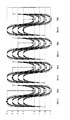
図5および図6は、データ伝送装置1から送信データとして伝送される伝送波形の一例である。なお、図5は前シンボル値B(k−1)が上位4シンボル(「+7」、「+5」、「+3」、「+1」)である場合にシンボル値B(k)が下位4シンボル(「−1」、「−3」、「−5」、「−7」)にマッピングされた伝送波形であり、図6は前シンボル値B(k−1)が下位4シンボルである場合にシンボル値B(k)が上位4シンボルにマッピングされた伝送波形である。データ伝送装置1から伝送される送信データは、上位4シンボルのうちのいずれかと、下位4シンボルのうちいずれかとが、交互にマッピングされた伝送波形である。
5 and 6 are examples of transmission waveforms transmitted from the
図5において、前シンボル値B(k−1)がシンボル「+7」の場合、シンボル値B(k)がシンボル「−1」、「−3」、「−5」、および「−7」を示すことによって、それぞれ送信データ「00」、「10」、「11」、および「01」が伝送される(図5の左端図)。前シンボル値B(k−1)がシンボル「+5」の場合、シンボル値B(k)が同様のシンボル値を示すことによって、それぞれ送信データ「01」、「00」、「10」、および「11」が伝送される(図5の左中図)。前シンボル値B(k−1)がシンボル「+3」の場合、シンボル値B(k)が同様のシンボル値を示すことによって、それぞれ送信データ「11」、「01」、「00」、および「10」が伝送される(図5の右中図)。そして、前シンボル値B(k−1)がシンボル「+1」の場合、シンボル値B(k)が同様のシンボル値を示すことによって、それぞれ送信データ「10」、「11」、「01」、および「00」が伝送される(図5の右端図)。 In FIG. 5, when the previous symbol value B (k−1) is the symbol “+7”, the symbol value B (k) is the symbols “−1”, “−3”, “−5”, and “−7”. As shown, transmission data “00”, “10”, “11”, and “01” are transmitted (the leftmost diagram in FIG. 5). When the previous symbol value B (k−1) is the symbol “+5”, the symbol value B (k) indicates the same symbol value, thereby transmitting data “01”, “00”, “10”, and “ 11 "is transmitted (the middle left diagram in FIG. 5). When the previous symbol value B (k−1) is the symbol “+3”, the symbol value B (k) indicates a similar symbol value, so that the transmission data “11”, “01”, “00”, and “ 10 "is transmitted (the middle diagram on the right in FIG. 5). When the previous symbol value B (k−1) is the symbol “+1”, the symbol value B (k) indicates the same symbol value, so that the transmission data “10”, “11”, “01”, And “00” are transmitted (the rightmost diagram in FIG. 5).
図6において、前シンボル値B(k−1)がシンボル「−7」の場合、シンボル値B(k)がシンボル「+7」、「+5」、「+3」、および「+1」を示すことによって、それぞれ送信データ「10」、「11」、「01」、および「00」が伝送される(図6の左端図)。前シンボル値B(k−1)がシンボル「−5」の場合、シンボル値B(k)が同様のシンボル値を示すことによって、それぞれ送信データ「11」、「01」、「00」、および「10」が伝送される(図6の左中図)。前シンボル値B(k−1)がシンボル「−3」の場合、シンボル値B(k)が同様のシンボル値を示すことによって、それぞれ送信データ「01」、「00」、「10」、および「11」が伝送される(図6の右中図)。そして、前シンボル値B(k−1)がシンボル「−1」の場合、シンボル値B(k)が同様のシンボル値を示すことによって、それぞれ送信データ「00」、「10」、「11」、および「01」が伝送される(図6の右端図)。 In FIG. 6, when the previous symbol value B (k−1) is the symbol “−7”, the symbol value B (k) indicates the symbols “+7”, “+5”, “+3”, and “+1”. , Transmission data “10”, “11”, “01”, and “00” are transmitted (the leftmost diagram in FIG. 6). When the previous symbol value B (k−1) is the symbol “−5”, the symbol value B (k) indicates a similar symbol value, thereby transmitting data “11”, “01”, “00”, and “10” is transmitted (the middle left diagram in FIG. 6). When the previous symbol value B (k−1) is the symbol “−3”, the symbol value B (k) indicates a similar symbol value, thereby transmitting data “01”, “00”, “10”, and “11” is transmitted (the middle right diagram in FIG. 6). When the previous symbol value B (k−1) is the symbol “−1”, the symbol value B (k) indicates the same symbol value, thereby transmitting data “00”, “10”, and “11”, respectively. , And “01” are transmitted (the rightmost diagram in FIG. 6).
図7は、データ伝送装置1から伝送されるトレーニング信号TSの伝送波形の一例である。上述したように、トレーニング信号TSは、ロック信号、トレーニングパターンヘッダ、およびトレーニングパターンを含んでおり、ロック信号→トレーニングパターンヘッダ→トレーニングパターンの順で送信される。
FIG. 7 is an example of a transmission waveform of the training signal TS transmitted from the
ロック信号は、受信側で送信側との同期確立するために送信側が送出する信号である。ロック信号の最大および最小振幅レベルに対応するタイミングを受信側で検出することによって送信側および受信側間での同期を確立する。ロック信号は、上述した上位4シンボルのうちのいずれかと、下位4シンボルのうちいずれかとが、交互にマッピングされた伝送波形となる。これによって、ロック信号には、固定の周波数成分が含まれることになり、受信側でのクロック再生が容易になる。 The lock signal is a signal transmitted from the transmission side in order to establish synchronization with the transmission side on the reception side. Synchronization between the transmitting side and the receiving side is established by detecting timing corresponding to the maximum and minimum amplitude levels of the lock signal at the receiving side. The lock signal has a transmission waveform in which any of the above-described upper 4 symbols and any of the lower 4 symbols are mapped alternately. As a result, the lock signal includes a fixed frequency component, and the clock reproduction on the receiving side is facilitated.
図8〜図11は、それぞれロック信号の伝送波形パターンの例を示している。第1の例として、ロック信号は、シンボル「+7」とシンボル「−7」とが交互にマッピングされた伝送波形で送出される(図8の例)。この場合、ロック信号は、最大振幅を有する伝送波形となる。第2の例として、ロック信号は、シンボル「+1」とシンボル「−1」とが交互にマッピングされた伝送波形で送出される(図9の例)。この場合、ロック信号は、最小振幅を有する伝送波形となる。第3の例として、固定されたパターンを繰り返してマッピングされた伝送波形で送出される(図10の例)。図10では、ロック信号は、1周期が8シンボルから構成されており、1〜6シンボル目で「+1」と「−1」とが交互に繰り返され、7シンボル目が「+7」、8シンボル目が「−7」となっている。第4の例は、ランダムパターンをマッピングした伝送波形で送出される(図11の例)。いずれの例においても、ロック信号は、上位4シンボルのうちのいずれかと、下位4シンボルのうちいずれかとが、交互にマッピングされた伝送波形となる。 8 to 11 show examples of transmission waveform patterns of the lock signal, respectively. As a first example, the lock signal is transmitted in a transmission waveform in which symbols “+7” and “−7” are alternately mapped (example in FIG. 8). In this case, the lock signal is a transmission waveform having the maximum amplitude. As a second example, the lock signal is transmitted in a transmission waveform in which symbols “+1” and “−1” are mapped alternately (example in FIG. 9). In this case, the lock signal is a transmission waveform having the minimum amplitude. As a third example, a fixed pattern is repeatedly transmitted and transmitted as a mapped transmission waveform (example in FIG. 10). In FIG. 10, the lock signal is composed of 8 symbols in one cycle, and “+1” and “−1” are alternately repeated in the 1st to 6th symbols, and the 7th symbol is “+7” and 8 symbols. The eyes are "-7". In the fourth example, a transmission waveform in which a random pattern is mapped is transmitted (example in FIG. 11). In either example, the lock signal has a transmission waveform in which any one of the upper 4 symbols and any one of the lower 4 symbols are mapped alternately.
図7に戻り、トレーニングパターンヘッダは、受信側のクロック同期確立後に送信側がトレーニングパターンに付与して送出する信号である。トレーニングパターンヘッダは、上記ロック信号に対して途切れることなく送出され、所定のシンボル(例えば、シンボル「+7」や「−7」)を所定期間連続してマッピングすることによって形成される。つまり、マッピング部63は、このトレーニングパターンヘッダをマッピング処理するとき、伝送信号が真横へ移動する特殊なマッピングを行う。このトレーニングパターンヘッダを受信側で検出することによって、ロック信号とトレーニングパターンとを区別することができる。受信側において、トレーニングパターンヘッダを逆マッピング処理(後述する)した場合、その差分値が0に近い値となる。例えば、図7で示すトレーニングパターンヘッダは、3シンボルから構成されており、全てのシンボルが「+7」で差分値が0となる最大の振幅レベルを継続している。なお、トレーニングパターンヘッダは、上述した上位4シンボルのうちのいずれかと、下位4シンボルのうちいずれかとが、交互にマッピングされるパターンを崩すものであれば、他の伝送波形でもかまわない。例えば、上位4シンボルのうちいずれかが連続してマッピングされた伝送波形でトレーニングパターンヘッダが構成されてもかまわない。 Returning to FIG. 7, the training pattern header is a signal that is transmitted from the transmission side after adding the clock synchronization on the reception side to the transmission pattern. The training pattern header is transmitted without interruption with respect to the lock signal, and is formed by mapping predetermined symbols (for example, symbols “+7” and “−7”) continuously for a predetermined period. That is, the mapping unit 63 performs a special mapping in which the transmission signal moves to the side when the training pattern header is mapped. By detecting this training pattern header on the receiving side, the lock signal and the training pattern can be distinguished. When the training pattern header is subjected to reverse mapping processing (described later) on the reception side, the difference value becomes a value close to zero. For example, the training pattern header shown in FIG. 7 is composed of three symbols, and the maximum amplitude level at which all symbols are “+7” and the difference value is 0 is continued. It should be noted that the training pattern header may be another transmission waveform as long as any of the above-described upper 4 symbols and any of the lower 4 symbols distort the pattern that is mapped alternately. For example, the training pattern header may be configured with a transmission waveform in which any one of the upper 4 symbols is continuously mapped.
トレーニングパターンは、上述した上位4シンボルのうちのいずれかと、下位4シンボルのうちいずれかとが、交互にマッピングされた伝送波形である。具体的には、トレーニングパターンは、上述した全ての送信シンボル値が含まれ、様々なパターンが現れるPNデータ等を上述したマッピングテーブルに基づいてマッピングしたパターンである。上記PNデータを予め決められたデータ系列とすることで、受信側においてトレーニングパターンのエミュートが可能となり、擬似ランダムデータ(PNデータ)による判定レベル設定が確実容易に行える。このトレーニングパターンは、固定長(トレーニングパターンヘッダの送出から所定時間経過で終了する)であるのが好ましい。なお、トレーニングパターンを可変長にして、当該トレーニングパターンの終了を示す信号を付与してもかまわない。 The training pattern is a transmission waveform in which any of the above-described upper 4 symbols and any of the lower 4 symbols are mapped alternately. Specifically, the training pattern is a pattern in which all the transmission symbol values described above are included and PN data and the like in which various patterns appear are mapped based on the mapping table described above. By making the PN data into a predetermined data series, it is possible to emulate the training pattern on the receiving side, and the determination level can be easily set with pseudo-random data (PN data). This training pattern is preferably of a fixed length (finished after a predetermined time has elapsed since the training pattern header was sent). Note that the training pattern may be variable in length and a signal indicating the end of the training pattern may be given.
トレーニングパターンが送出された後、途切れることなく上述したマッピングテーブルに基づいてマッピングされた送信データの送信が開始される。受信側では、トレーニング信号TS全体を受信した後、送信データの受信を行う。このようなトレーニング信号を用いることによって、初期動作の際、受信側ではクロック同期の確立および多値判定レベルの設定を行うことができる。そして、受信側では、多値判定レベルに基づいて送信データの信号レベルを判定し、その判定結果を逆マッピングすることによって、データ再生が可能となる。 After the training pattern is transmitted, transmission of transmission data mapped based on the above-described mapping table is started without interruption. On the receiving side, after receiving the entire training signal TS, transmission data is received. By using such a training signal, it is possible to establish clock synchronization and set a multi-level determination level on the receiving side during the initial operation. On the receiving side, data reproduction is possible by determining the signal level of transmission data based on the multilevel determination level and reverse mapping the determination result.
図2に戻り、受信部5は、クロック再生部50、差動レシーバ51、ADC(アナログ・デジタル・コンバータ)52、ロールオフフィルタ53、差分算出部54、逆マッピング部55、P/S(パラレル/シリアル)変換部56、判定レベル設定部57、トレーニング信号検出部58、および教師信号生成部59を有している。なお、ロールオフフィルタ53、差分算出部54、逆マッピング部55、およびP/S変換部56によって、受信側の信号処理部を形成している。
Returning to FIG. 2, the
差動レシーバ51は、伝送路80から入力する差動信号を電圧信号に変換してADC52に出力する。上述したように、伝送路80が有する2本1組の導線に対してプラス側とマイナス側との電気信号が1つのペアとして伝送しており、差動レシーバ51は、プラス側とマイナス側との差から信号を判断するため、外部からの電気的影響に対して効力を発揮する。そして、ADC52は、差動レシーバ51から出力される電圧信号をデジタル信号に変換する。
The differential receiver 51 converts the differential signal input from the
ロールオフフィルタ53は、ADC52から出力されるデジタル信号のノイズ除去を行う波形整形用のFIRフィルタであり、例えば、シンボルレートの16倍のFIRフィルタが使用される。上述した送信側のロールオフフィルタ64と合わせ、符号間干渉のないロールオフ特性を実現する。差分算出部54は、後述するクロック再生部50で検出したデータシンボルタイミングに基づいて、ロールオフフィルタ53から出力された受信シンボル値と前シンボル値との差分値を演算する。そして、差分算出部54は、判定レベル設定部57で設定された判定レベルに基づいて、上記差分値毎にデータ判定を行って、その判定値を逆マッピング部55に出力する。このように、受信したシンボル値を前シンボル値に対する差分値で判定することによって、送信側から受信側のデータ伝送装置1に伝送する際の全体的な電圧変化をキャンセルすることができる。
The roll-off filter 53 is a waveform shaping FIR filter that removes noise from the digital signal output from the ADC 52. For example, an FIR filter that is 16 times the symbol rate is used. Together with the above-described transmission-side roll-off filter 64, a roll-off characteristic without intersymbol interference is realized. The
逆マッピング部55は、クロック再生部50で検出したデータシンボルタイミングに基づいて、上記判定値を用いて送信側のマッピング部63でマッピングする前のデータに復号する。この逆マッピング部55における逆マッピング処理によって、上記判定値がパラレルデータに変換される。P/S変換部56は、逆マッピング部55で変換されたパラレルデータをシリアルのデジタルデータRXに変換して、コントローラ2に出力する。
Based on the data symbol timing detected by the clock recovery unit 50, the inverse mapping unit 55 decodes the data before mapping by the mapping unit 63 on the transmission side using the determination value. By the inverse mapping process in the inverse mapping unit 55, the determination value is converted into parallel data. The P / S conversion unit 56 converts the parallel data converted by the inverse mapping unit 55 into serial digital data RX and outputs the serial digital data RX to the
クロック再生部50は、ADC52から出力される伝送路80から受信した信号のクロック成分を再生することによって、伝送路のクロック再生を行い、上述した伝送波形の最大あるいは最小ポイントとなるデータシンボルタイミングを検出する。そして、クロック再生部50で再生されたクロックは、受信側の信号処理部のクロックとして用いられる。また、クロック再生部50で再生されたクロックは、クロック制御部7に出力され受信側PLLのリファレンスクロック入力として用いられる。
The clock recovery unit 50 recovers the clock of the transmission line by reproducing the clock component of the signal received from the
判定レベル設定部57は、差分算出部54で演算された差分値ddに対して、その差分値ddを閾値判定するための判定レベルを設定する。トレーニング信号検出部58は、他のデータ伝送装置1から伝送されたトレーニング信号TSのトレーニングパターンヘッダおよびトレーニングパターンを検出する。教師信号生成部59は、トレーニング信号検出部58がトレーニング信号TSのトレーニングパターンヘッダおよびトレーニングパターンを検出した際、そのトレーニングパターンと同じデータパターンを有し、かつ当該トレーニングパターンと同期した教師信号MSを判定レベル設定部57に出力する。なお、これらの動作の詳細については、後述する。
The determination
次に、図12を参照して、判定レベル設定部57の構造について説明する。なお、図12は、判定レベル設定部57の構成を示すブロック図である。
Next, the structure of the determination
図12において、判定レベル設定部57は、理想値記憶部571、判定レベル値演算回路572、判定レベル記憶部573、比較回路574、およびセレクタ575を有している。理想値記憶部571は、差分算出部54で演算されるトレーニングパターンにおける各差分値の理想値を、それぞれ保持するレジスタ576a〜576nを有している。レジスタ576a〜576nは、セレクタ575と接続されている。セレクタ575は、教師信号生成部59から出力される教師信号MSに基づいて、現在入力しているトレーニングパターンの差分値に相当する理想値記憶部571に保持された理想値を、比較回路574に出力する。比較回路574は、現在入力しているトレーニングパターンの差分値と、それに相当する理想値記憶部571に保持された理想値とを比較する。そして、比較回路574は、当該理想値に後述する所定の演算を行って、その理想値を保持する理想値記憶部571のレジスタ576a〜576nを、演算後の理想値に更新する。
12, the determination
判定レベル値演算回路572は、理想値記憶部571に保持された各理想値を用いて、隣接する理想値に対する判定レベルをそれぞれ演算して、判定レベル記憶部573に出力する。具体的には、判定レベル値演算回路572は、隣接する理想値に対する判定レベルを、それぞれの理想値を平均して演算する。判定レベル記憶部573は、隣接する理想値の間に応じた上記判定レベルをそれぞれ保持するレジスタ577a〜577mを有している。
The determination level
次に、図13を参照して、判定レベル設定部57で設定される判定レベルおよび判定値と、差分算出部54で演算される差分値との一例について説明する。なお、図13は、判定レベル設定部57の判定レベルを説明するための図である。
Next, an example of the determination level and determination value set by the determination
上述したように、8値マッピングを行う場合、送信側のデータ伝送装置1では、データシンボルを8個の信号レベルにマッピングしている(図3〜図6参照)。具体的には、データシンボルを「+7」、「+5」、「+3」、「+1」、「−1」、「−3」、「−5」、および「−7」の8個の信号レベル(送信シンボル値)のいずれかにマッピングするように定められている。そして、送信シンボル値は、前シンボル値の極性に対して、その正負が交互になるようにマッピングされ、前シンボル値との差分値に対して、送信データが一意に決まるようにマッピングされている。具体的には、小さい差分値から順に、「−14」、「−12」、「−10」、「−8」、「−6」、「−4」、「−2」、「+2」、「+4」、「+6」、「+8」、「+10」、「+12」、および「+14」の14種類の差分値となる。これらの差分値は、送信側のデータ伝送装置1でマッピングされる送信側の差分値である。つまり、受信側のデータ伝送装置1で受信した伝送波形においては、上述した差分値を正確に保持した状態で伝送されないことが多い。したがって、受信側のデータ伝送装置1は、受信して算出した受信側の差分値が、どの上記送信側の差分値を示しているのか判定する必要がある。この判定した結果が判定値であり、当該判定値は、上述した送信側における14種類の差分値の何れかを示す。
As described above, when performing 8-level mapping, the
図13において、判定レベル設定部57は、小さい差分値から順に、それぞれP1〜P14として上記受信側の差分値を取り扱う。そして、判定レベル設定部57は、上記隣接する差分値P1〜P14の間にそれぞれの判定レベルR1〜R13を設定する。これらの判定レベルR1〜R13は、上記判定値を判定する際の判定境界となる数値である。例えば、判定レベルR1は、受信側の差分値P1およびP2の間に設定され、受信側の差分値P1およびP2に相当するそれぞれの判定値(「−14」および「−12」)の判定境界となる。判定レベルR2は、受信側の差分値P2およびP3の間に設定され、受信側の差分値P2およびP3に相当するそれぞれの判定値(「−12」および「−10」)の判定境界となり、他の判定レベルR3〜R13も同様に設定される。そして、差分算出部54(図2参照)は、算出した差分値が判定レベルR1より小さな値の場合、判定値「−14」を逆マッピング部55に出力する。また、差分算出部54は、算出した差分値が判定レベルR1より大きく、かつ判定レベルR2より小さな値の場合、判定値「−12」を逆マッピング部55に出力する。このように、差分算出部54は、判定レベル設定部57に設定された判定レベルR1〜R13と算出した差分値とを比較して、その比較結果の数値領域に相当する判定値を逆マッピング部55に出力する。
In FIG. 13, the determination
このような判定値を判定するために、データ伝送装置1では、互いにデータ伝送を行う前に判定レベル設定が行われる。この判定レベル設定の際、送信側のデータ伝送装置1からトレーニング信号TSが送信される。上述したように、トレーニング信号TSは、ロック信号、トレーニングパターンヘッダ、およびトレーニングパターンを含んでいる。トレーニングパターンは、各データ伝送装置1間で既知のデータパターン(PNデータに基づくパターン)であり、上記全ての送信シンボル値が含まれるPNパターン信号等が用いられる。送信側のデータ伝送装置1は、電源投入時等にこのトレーニング信号TSを出力する。
In order to determine such a determination value, the
受信側のデータ伝送装置1は、トレーニング信号TSが有するロック信号を受信すると、クロック再生部50でクロック再生を行い、当該ロック信号の最大あるいは最小ポイントとなるデータシンボルタイミングを検出する。そして、このデータシンボルタイミングが、判定レベル設定部57、トレーニング信号検出部58、および教師信号生成部59のクロックとして以降の処理に用いられる。
When the
次に、受信側のデータ伝送装置1のトレーニング信号検出部58は、ロック信号に続いて受信したトレーニングパターンヘッダを検出する。トレーニング信号検出部58は、差分算出部54で算出された差分値ddがdd≒0のとき、トレーニングパターンヘッダを検出する。例えば、図7で示したトレーニング信号TSを受信した場合、3シンボルが全て「+7」となるトレーニングパターンヘッダに対して、差分算出部54では差分値dd≒0となる算出結果を2回送出する。トレーニング信号検出部58は、差分算出部54から送出される差分値dd≒0を検出し、その後に受信するトレーニング信号TSのトレーニングパターンを用いて、判定レベル設定部57および教師信号生成部59による判定レベル設定が開始される。
Next, the training signal detector 58 of the
具体的には、差分算出部54は、トレーニング信号TSが入力した場合、クロック再生部50から指示されるデータシンボルタイミングに基づいて、前シンボル値に対する受信シンボル値の差分を算出し、この算出結果を受信側の差分値ddとして判定レベル設定部57およびトレーニング信号検出部58に出力する。ここで、トレーニング信号TSに含まれるトレーニングパターンヘッダは、例えば、最大あるいは最小の振幅レベルを所定期間継続するパターンであるため、差分値ddが所定期間「0」を示すことになる。この場合、トレーニング信号検出部58は、差分算出部54から出力される差分値ddが「0」となる期間を検出することによって、トレーニング信号TSのトレーニングパターンヘッダが入力したことを検出する。また、トレーニング信号TSに含まれるトレーニングパターンは、上記全ての送信シンボル値が含まれる予め決められたPNデータに基づいた信号等が用いられている。したがって、差分算出部54が上記トレーニングパターンを用いて算出される差分値ddは、受信側のデータ伝送装置1で受信する可能性のある全ての差分値が含まれている。このトレーニングパターンは、各データ伝送装置1間で既知のデータパターンであり、教師信号生成部59は、トレーニング信号検出部58がトレーニングパターンヘッダを検出した通知に基づいて、現在入力しているトレーニングパターンの差分値ddがどの送信側の差分値を示すものかを表す教師信号MSを、クロック再生部50から指示されるデータシンボルタイミングに基づいて判定レベル設定部57に出力する。
Specifically, when the training signal TS is input, the
なお、トレーニングパターンヘッダが、上位4シンボルのうちのいずれかと、下位4シンボルのうちいずれかとが、交互にマッピングされるパターンを崩すものである場合、トレーニング信号検出部58は、その崩れたパターン(例えば、上位4シンボルのうちのいずれかが連続するパターン)を検出することによって、トレーニングパターンヘッダを検出してもかまわない。 In the case where the training pattern header is one that breaks a pattern in which any one of the upper 4 symbols and any one of the lower 4 symbols are mapped alternately, the training signal detection unit 58 uses the broken pattern ( For example, the training pattern header may be detected by detecting a pattern in which any one of the upper 4 symbols is continuous.
図12および図14を参照して、上記トレーニングパターンの差分値ddを用いた判定レベル設定部57の判定レベル設定動作について説明する。差分算出部54から出力されたトレーニングパターンの差分値ddは、比較回路574に入力する。一方、教師信号生成部59から出力された教師信号MSは、セレクタ575に入力する。セレクタ575は、教師信号MSによって指示される差分値に応じて、レジスタ576a〜576nを選択し、その選択されたレジスタ576a〜576nに記憶されているデータを比較回路574へ出力する。
The determination level setting operation of the determination
比較回路574は、入力された差分値ddが最初である場合、その差分値ddを受信する理想的な値(以下、理想値と記載する)として、現在選択されているレジスタ576a〜576nにその差分値ddを記憶させる。この処理が、全てのレジスタ576a〜576nに対して行われることによって、レジスタ576a〜576nが記憶する受信側における差分値P1〜P14の理想値の初期値がそれぞれ設定される(図14の初期値設定の状態)。
When the input difference value dd is the first, the
上記初期値の設定の後、比較回路574は、差分算出部54から出力された差分値ddとセレクタ575から出力されたその差分値ddに応じた理想値とを比較する。そして、比較回路574は、差分値ddが理想値より大きい場合、当該理想値に所定の数値を加算して、現在選択されているレジスタ576a〜576nをその所定の数値を加算した理想値に更新する(図14の更新Aの状態)。また、比較回路574は、差分値ddが理想値より小さい場合、当該理想値から所定の数値を減算して、現在選択されているレジスタ576a〜576nをその所定の数値を減算した理想値に更新する(図14の更新Bの状態)。また、比較回路574は、差分値ddが理想値と等しい場合、現在選択されているレジスタ576a〜576nを当該理想値に更新(つまり、理想値の変化なし)する。
After setting the initial value, the
例えば、比較回路574にトレーニングパターンの差分値P2が入力する。このとき、セレクタ575は、レジスタ576bを教師信号MSに基づいて選択し、レジスタ576bに記憶されている差分値P2の理想値を比較回路574に出力する。そして、比較回路574は、差分値P2が差分値P2の理想値より大きい場合、差分値P2の理想値に所定の数値を加算して、レジスタ576bを更新する(図14の更新Aの状態)。一方、比較回路574は、差分値P2が差分値P2の理想値より小さい場合、差分値P2の理想値から所定の数値を減算して、レジスタ576bを更新する(図14の更新Bの状態)。なお、比較回路574が加算/減算する所定の数値については、後述する。
For example, the difference value P2 of the training pattern is input to the
このような更新が、全てのレジスタ576a〜576nに対して繰り返されることによって、レジスタ576a〜576nが記憶する受信側の差分値P1〜P14の理想値がそれぞれ設定される。なお、上述したようにトレーニング信号TSに含まれるトレーニングパターンが固定長であるため、判定レベル設定部57が有するカウンタ(図示せず)のカウントに基づいて、上記更新を終了する。一例として、上記カウンタがトレーニングパターンヘッダの受信から固定長のトレーニングパターンを受信終了するまでの時間をカウントする。そして、教師信号生成部59が教師信号MSの出力を停止し、比較回路574によるレジスタ576a〜576nの更新を終了し、受信側の差分値P1〜P14の理想値がそれぞれ設定される。なお、トレーニングパターンを可変長にして、当該トレーニングパターンの終了を示す信号を付与している場合、トレーニング信号検出部58がトレーニングパターンの終了を示す信号を検出して、上記更新を終了してもかまわない。
By repeating such an update for all the
そして、判定レベル値演算回路572は、理想値記憶部571のレジスタ576a〜576nに設定された受信側の差分値P1〜P14の理想値を用いて、判定レベルR1〜R13を演算する。判定レベル値演算回路572は、互いに隣接する理想値の間の判定レベルを演算する場合、それら理想値を平均することによって当該判定レベルを演算する。例えば、判定レベル値演算回路572は、判定値「−14」および「−12」の間の判定レベルR1を演算する場合、レジスタ576aおよび576bにそれぞれ記憶されている差分値P1およびP2の理想値を平均することによって演算する(図14の判定レベル設定の状態)。そして、判定レベル値演算回路572は、演算した判定レベルR1〜R13を、それぞれ判定レベル記憶部573が有するレジスタ577a〜577mに記憶させる。そして、判定レベル設定部57の判定レベル設定処理が終了し、データ伝送装置1間のデータ伝送が開始される。
Then, the determination level
なお、上述では、レジスタ577a〜577mに設定される判定レベルを、互いに隣接する理想値を平均することによって設定したが、これらの判定レベルは、当該判定レベルに隣接する理想値に所定の値を乗算することによって設定してもかまわない。例えば、判定値「−10」および「−8」の間の判定レベルR3を演算する場合、レジスタ576cに記憶されている差分値P3の理想値に所定の値(例えば、0.9)を乗算することによって設定してもかまわない。
In the above description, the determination levels set in the
このように、理想値記憶部571に記憶される理想値は、上記トレーニングパターンで受信したそれぞれの差分値ddを全て考慮された結果で設定されている。つまり、上記トレーニングパターンに突発的なノイズが加わったり急激なレベル変動が生じたりすることによる急峻な変動が生じても、これらの値が単独で理想値に設定されることはなく、全体の差分値の傾向を含んだ適切な理想値が、差分値P1〜P14毎に設定される。また、判定レベルR1〜R13は、これら適切な理想値を用いて演算されるため、判定レベルR1〜R13を用いて、データ伝送におけるデータ判定を適切に行うことができる。
Thus, the ideal value stored in the ideal
次に、判定レベル設定部57が理想値に対して加算/減算する上記所定の数値について、具体的な一例を説明する。例えば、差分算出部54が出力する差分値ddは、その差分値の絶対値を10ビット(0〜1023)に符号を1ビット(+または−)を加えて示される。この場合、差分値ddは、−1023〜+1023の2047階調の値をとることになる。ここで、理想値に対して加算/減算する上記所定の数値は、常に理想値に対する差分値ddの差以下の値に設定されることが好ましい。これは、上記所定の数値が理想値に対する差分値ddの差より大きな値に設定されると、理想値に対する現実の差分値ddにおける差以上の数値に新たな理想値が更新され、全体の差分値の傾向を含んだ適切な理想値が設定できなくなる。したがって、上記所定の数値を常に上記差以下に設定するために、差分値ddの単位階調以下の値(例えば、差分値ddの2047階調に対する0.25階調)に上記所定の数値を設定するのが好ましい。
Next, a specific example of the predetermined numerical value that is added / subtracted from the ideal value by the determination
上記所定の数値(0.25階調)を判定レベル設定部57で取り扱うために、判定レベル設定部57では上記差分値ddの絶対値を12ビットに拡張し、理想値の絶対値も12ビットに拡張する。そして、拡張した下位2ビットで小数点以下の階調(0.00、0.25、0.50、0.75)を取り扱う。これによって、差分値ddが理想値より大きい場合は、その理想値を「1」(上記12ビットにおける「1」、すなわち0.25階調)増加させ、差分値ddが理想値より小さい場合は、その理想値を「1」減少させれば、差分値ddの単位階調に対して0.25階調の加算/減算を行うことが可能となる。したがって、理想値を増減させる量(0.25階調)を、差分値ddの1階調の値(1.00階調)より小さい値に設定しているため、受信した差分値ddを超えて理想値が更新されることがなく、微少量ずつ理想値を増減させることができる。
In order for the determination
なお、上述では、判定レベル設定部57が理想値に対して加算/減算する所定の数値を一定値で説明したが、当該数値は一定値でなくてもかまわない。例えば、上記所定の数値は、理想値に対する差分値ddの差に応じて、重み付けを行った数値(すなわち、差が大きければ加算/減算する数値も大きくする)でもかまわない。重み付けを行った数値を用いて加算/減算しても、理想値を適切な値に設定することができる。
In the above description, the predetermined numerical value that is added / subtracted from the ideal value by the determination
差分算出部54は、データ伝送時には、ロールオフフィルタ53から出力された受信シンボル値と前シンボル値との差分値を演算し、上述したように判定レベル設定部57に設定された判定レベルR1〜R13を用いて、当該差分値毎にデータ判定を行って、その判定値を逆マッピング部55に出力する。例えば、差分算出部54は、上記差分値が判定レベルR1およびR2の間にあるとき、判定値「−12」を逆マッピング部55に出力する。そして、逆マッピング部55では、送信データおよび送信側の差分値の対応関係(図4参照)と逆の対応関係を用いて、上記判定値を送信側のマッピング部63でマッピングする前のパラレルデータに正確に復号することができる。
The
このように、本実施形態のデータ伝送装置は、多値マッピングされて電気通信された伝送波形に対して、そのシンボル値を判定する際の判定レベルを、初期化動作の際にトレーニングパターンで受信したそれぞれの差分値を総合的に考慮した結果に基づいて設定する。つまり、トレーニングパターンに突発的なノイズが加わったり急激なレベル変動が生じたりすることによる急峻な変動が生じても、これらの値が単独で判定レベルに設定されることはなく、全体の差分値の傾向を含んだ適切な判定レベルが設定される。したがって、これらの判定レベルを用いて、データ伝送のシンボル値に対して判定することによって、正確なデータ判定を行うことができる。 As described above, the data transmission apparatus according to the present embodiment receives a determination level for determining a symbol value of a transmission waveform subjected to multi-value mapping and telecommunications in a training pattern during an initialization operation. It sets based on the result which considered each difference value comprehensively considered. In other words, even if sudden fluctuations occur due to sudden noise or sudden level fluctuations in the training pattern, these values are not set as judgment levels independently, but the overall difference value An appropriate judgment level including the tendency is set. Therefore, accurate determination of data can be performed by determining the symbol value of data transmission using these determination levels.
また、本実施形態の判定レベルを設定するために必要なレジスタの数は、従来と比較して大幅に削減される。具体的には、本実施形態の理想値記憶部および判定レベル記憶部には、設定する理想値および判定レベルの数に対してそれぞれ同数のレジスタが設けられる。一方、従来の最大最小信号レベル記憶部には、設定する信号レベルの数に対して2倍のレジスタが必要である。なお、図17で示した従来の最大最小信号レベル記憶部が有するレジスタの数は、信号レベルに応じて設定されているために、図12で示した本実施形態の理想値記憶部が有するレジスタの数に対してその削減効果が顕著に表れていない。従来の方式で差分値によって判定する場合は、本実施形態の理想値記憶部が有するレジスタの数に対して、2倍のレジスタが必要となる。さらに、本実施形態の判定レベルを設定するために必要な比較回路およびセレクタの数も、従来と比較して半分の数で構成される。つまり、本実施形態の回路規模を従来より小さくして、適切な判定レベルを設定することができる。 In addition, the number of registers necessary for setting the determination level of the present embodiment is greatly reduced as compared with the prior art. Specifically, the ideal value storage unit and the determination level storage unit of the present embodiment are provided with the same number of registers as the number of ideal values and determination levels to be set. On the other hand, the conventional maximum / minimum signal level storage unit requires twice as many registers as the number of signal levels to be set. Note that the number of registers included in the conventional maximum / minimum signal level storage unit illustrated in FIG. 17 is set according to the signal level, and thus the registers included in the ideal value storage unit of the present embodiment illustrated in FIG. The reduction effect does not appear remarkably with respect to the number. When the determination is made based on the difference value in the conventional method, twice as many registers as the number of registers included in the ideal value storage unit of the present embodiment are required. Further, the number of comparison circuits and selectors necessary for setting the determination level of this embodiment is also half that of the prior art. That is, it is possible to set an appropriate determination level by making the circuit scale of the present embodiment smaller than the conventional one.
なお、上述では、レジスタ576a〜576nに設定される理想値の初期値を比較回路574に最初に入力した差分値ddによって設定したが、これらの理想値の初期値は、予め設定された固定的な値でもかまわない。この場合、比較回路574に最初に入力した差分値ddも、2回目以降に入力した差分値ddと同様の処理が行われる。
In the above description, the initial value of the ideal value set in the
また、本実施形態の説明では、8値マッピングして伝送する方式を用いたが、本発明はこの伝送方式に限定されない。例えば、4値マッピングして伝送する方式でも同様に本発明を適用することができる。また、本実施形態の説明では、前シンボル値に対する差分値によってデータ判定する方式を用いたが、シンボル値を直接判定する方式でも、同様に本発明を適用できることは言うまでもない。 Further, in the description of the present embodiment, the transmission method using 8-value mapping is used, but the present invention is not limited to this transmission method. For example, the present invention can be similarly applied to a system in which four-value mapping is performed for transmission. Further, in the description of the present embodiment, the method of determining data based on the difference value with respect to the previous symbol value is used. However, it goes without saying that the present invention can be similarly applied to a method of directly determining the symbol value.
本発明にかかるデータ受信方法、データ受信装置、およびデータ伝送システムは、多値電気信号等を用いて通信を行う際に、受信信号の信号レベルに応じた正確なデータ判定を行うことができ、リング型等で各装置を伝送路によって接続し、互いに判定レベルを設定して一方向の電気通信を行うシステムにおける受信方法、当該システムに含まれる装置、および当該システム等として有用である。 The data receiving method, the data receiving apparatus, and the data transmission system according to the present invention can perform accurate data determination according to the signal level of the received signal when performing communication using a multi-value electric signal or the like, It is useful as a reception method in a system in which each device is connected by a transmission line, such as a ring type, and a determination level is set to each other to perform one-way telecommunications, a device included in the system, and the system.
1…データ伝送装置
2…コントローラ
3…MPU
4…送受信部
5…受信部
50…クロック再生部
51…差動レシーバ
52…ADC
53、64…ロールオフフィルタ
54…差分算出部
55…逆マッピング部
56…P/S変換部
57…判定レベル設定部
571…理想値記憶部
572…判定レベル値演算回路
573…判定レベル記憶部
574…比較回路
575、61…セレクタ
576、577…レジスタ
58…トレーニング信号検出部
59…教師信号生成部
6…送信部
62…S/P変換部
63…マッピング部
65…DAC
66…差動ドライバ
67…トレーニング信号発生部
7…クロック制御部
10…接続機器
80…伝送路
DESCRIPTION OF
4. Transmission /
53, 64 ... Roll-
66 ...
Claims (43)
初期動作の際、
前記伝送信号の複数の信号レベルが既知の変動パターンで送信されたトレーニングパターンから、前記シンボルに応じて信号レベルを検出し、
受信する前記複数の信号レベルの理想値を所定の条件に基づいて初期設定してそれぞれ保持し、
前記トレーニングパターンのシンボルに応じて、新たに検出した信号レベルと既に保持している理想値とを比較し、その大小関係に基づいて既に保持している理想値を所定量増減して新たな理想値にそれぞれ更新することを繰り返し、
前記トレーニングパターンのシンボルに応じてそれぞれ更新された理想値を用いて、データ受信の際にデータ送信される伝送信号の複数の信号レベルをそれぞれ区別して判定するための判定レベルをそれぞれ設定する、データ受信方法。 A data reception method for receiving a transmission signal transmitted by mapping each symbol of transmission data to one of a plurality of signal levels,
During initial operation,
From a training pattern in which a plurality of signal levels of the transmission signal are transmitted in a known variation pattern, a signal level is detected according to the symbol,
The ideal values of the plurality of signal levels to be received are initially set based on a predetermined condition, and are held respectively.
In accordance with the symbol of the training pattern, the newly detected signal level is compared with the ideal value already held, and the ideal value already held is increased or decreased by a predetermined amount based on the magnitude relationship, thereby creating a new ideal Repeatedly updating each value,
Data that sets determination levels for distinguishing and determining a plurality of signal levels of transmission signals transmitted during data reception using ideal values that are respectively updated according to the symbols of the training pattern Reception method.
新たに検出した信号レベルが既に保持している理想値より小さいときには、既に保持している理想値から一定量減算して新たな理想値に更新することを特徴とする、請求項1乃至4のいずれかに記載のデータ受信方法。 According to the symbol of the training pattern, the newly detected signal level is compared with the already held ideal value, and when the newly detected signal level is larger than the already held ideal value, it is already held. Add a certain amount to the ideal value and update it to a new ideal value.
5. When the newly detected signal level is smaller than an already held ideal value, a predetermined amount is subtracted from the already held ideal value to update to a new ideal value. The data receiving method according to any one of the above.
新たに検出した信号レベルが既に保持している理想値より小さい場合には、既に保持している理想値から当該レベル差以下で、かつ当該レベル差に応じて重み付けした量を減算して新たな理想値に更新することを特徴とする、請求項1乃至4のいずれかに記載のデータ受信方法。 According to the symbol of the training pattern, the newly detected signal level is compared with the ideal value already held, and if the newly detected signal level is larger than the ideal value already held, it is already held. Updated to a new ideal value that is equal to or less than the level difference and adds an amount weighted according to the level difference,
If the newly detected signal level is smaller than the ideal value already held, a new value is obtained by subtracting an amount that is equal to or smaller than the level difference and weighted according to the level difference from the already held ideal value. 5. The data receiving method according to claim 1, wherein the data is updated to an ideal value.
前記判定レベルは、データ受信の際に前記マッピングされてデータ送信される伝送信号におけるシンボルに応じた複数の信号レベルを、それぞれ当該シンボルに対する直前のシンボルの信号レベルとの差分によって区別して判定するために設定することを特徴とする、請求項1乃至7のいずれかに記載のデータ受信方法。 Detecting a plurality of signal levels corresponding to the symbols in the training pattern by a difference from the signal level of the immediately preceding symbol with respect to the symbol;
The determination level is determined by distinguishing a plurality of signal levels corresponding to symbols in the transmission signal to be mapped and transmitted during data reception based on differences from the signal level of the immediately preceding symbol with respect to the symbol. The data receiving method according to claim 1, wherein the data receiving method is set as follows.
前記複数の信号レベルは、相対的に信号レベルが高い上位群と相対的に信号レベルが低い下位群とを含んでおり、
前記トレーニングパターンおよびロック信号は、前記上位群から選ばれた信号レベルと前記下位群から選ばれた信号レベルとが交互になるようにマッピングされており、
前記ヘッダは、シンボルが同じ信号レベルにマッピングされていることを特徴とする、請求項1に記載のデータ受信方法。 The training pattern is transmitted with a predetermined header after a lock signal including a clock component for establishing synchronization with the transmission side is transmitted,
The plurality of signal levels include an upper group having a relatively high signal level and a lower group having a relatively low signal level;
The training pattern and the lock signal are mapped so that the signal level selected from the upper group and the signal level selected from the lower group are alternated,
The data reception method according to claim 1, wherein the header has symbols mapped to the same signal level.
前記ロック信号に含まれるクロック成分を再生して送信側との同期を確立し、
前記同期が確立されたクロック毎の信号レベルの内、隣接する信号レベルが同じであるとき、前記ヘッダを検出することを特徴とする、請求項11に記載のデータ受信方法。 During the initial operation,
Regenerate the clock component included in the lock signal to establish synchronization with the transmission side,
12. The data receiving method according to claim 11, wherein the header is detected when adjacent signal levels are the same among signal levels for each clock for which synchronization has been established.
前記理想値をそれぞれ更新する繰り返しは、前記ヘッダの受信から前記所定の時間を経過することによって終了することを特徴とする、請求項11に記載のデータ受信方法。 The training pattern is transmitted for a predetermined time from the transmission of the header,
12. The data receiving method according to claim 11, wherein the repetition of updating each of the ideal values ends when the predetermined time elapses from reception of the header.
初期動作の際に、前記データ伝送装置から送信された前記伝送信号の複数の信号レベルが既知の変動パターンで形成されたトレーニングパターンから、前記シンボルに応じて信号レベルを検出する信号レベル検出部と、
受信する前記複数の信号レベルの理想値を所定の条件に基づいて初期設定してそれぞれ記憶した後、所定の処理に基づいて当該理想値が更新される複数の記憶手段を有する理想値記憶部と、
前記トレーニングパターンのシンボルに応じて、前記信号レベル検出部が新たに検出した信号レベルと既に前記記憶手段が記憶している理想値とを比較し、その大小関係に基づいて当該記憶手段が記憶している理想値を所定量増減して新たな理想値にそれぞれ当該記憶手段の値を更新することを繰り返す比較更新部と、
前記複数の記憶手段にそれぞれ更新されて記憶している理想値を用いて、データ受信の際に前記データ伝送装置からデータ送信される伝送信号の複数の信号レベルをそれぞれ区別して判定するための判定レベルをそれぞれ演算する判定レベル値演算部と、
前記判定レベル値演算部が演算した判定レベルをそれぞれ記憶する判定レベル記憶部とを備える、データ受信装置。 A data receiving device connected to another data transmission device via a transmission line, for receiving a transmission signal transmitted by mapping each symbol of transmission data to one of a plurality of signal levels,
A signal level detection unit that detects a signal level according to the symbol from a training pattern in which a plurality of signal levels of the transmission signal transmitted from the data transmission device are formed in a known variation pattern in an initial operation; ,
An ideal value storage unit having a plurality of storage means for initializing and storing ideal values of the plurality of signal levels to be received based on a predetermined condition and then storing the ideal values based on a predetermined process; ,
In accordance with the symbol of the training pattern, the signal level newly detected by the signal level detection unit is compared with the ideal value already stored in the storage unit, and the storage unit stores the value based on the magnitude relationship. A comparison update unit that repeats updating the value of the storage means to a new ideal value by increasing or decreasing the ideal value by a predetermined amount;
Determination for distinguishing and determining a plurality of signal levels of transmission signals transmitted from the data transmission apparatus at the time of data reception, using ideal values respectively updated and stored in the plurality of storage means A judgment level value calculation unit for calculating each level;
A data receiving apparatus comprising: a determination level storage unit that stores the determination levels calculated by the determination level value calculation unit.
前記信号レベル検出部が新たに検出した信号レベルが既に前記記憶手段が記憶している理想値より大きい場合には、既に当該記憶手段が記憶している理想値を一定量加算して新たな理想値に当該記憶手段の値を更新し、
前記信号レベル検出部が新たに検出した信号レベルが既に前記記憶手段が記憶している理想値より小さい場合には、既に当該記憶手段が記憶している理想値から一定量減算して新たな理想値に当該記憶手段の値を更新することを特徴とする、請求項14乃至17のいずれかに記載のデータ受信装置。 The comparison update unit, according to the symbol of the training pattern,
When the signal level newly detected by the signal level detection unit is larger than the ideal value already stored in the storage unit, the ideal value already stored in the storage unit is added by a certain amount to obtain a new ideal level. Update the value of the storage means to the value,
If the signal level newly detected by the signal level detection unit is smaller than the ideal value already stored in the storage means, a new ideal value is subtracted from the ideal value already stored in the storage means. The data receiving apparatus according to claim 14, wherein the value of the storage unit is updated to a value.
前記信号レベル検出部が新たに検出した信号レベルが既に前記記憶手段が記憶している理想値より大きい場合には、既に当該記憶手段が記憶している理想値に当該レベル差以下で、かつ当該レベル差に応じて重み付けした量を加算して新たな理想値に当該記憶手段の値を更新し、
前記信号レベル検出部が新たに検出した信号レベルが既に前記記憶手段が記憶している理想値より小さい場合には、既に当該記憶手段が記憶している理想値から当該レベル差以下で、かつ当該レベル差に応じて重み付けした量を減算して新たな理想値に当該記憶手段の値を更新することを特徴とする、請求項14乃至17のいずれかに記載のデータ受信装置。 The comparison update unit, according to the symbol of the training pattern,
If the signal level newly detected by the signal level detection unit is larger than the ideal value already stored in the storage means, the ideal value already stored in the storage means is less than the level difference and Add the weighted amount according to the level difference and update the value of the storage means to a new ideal value,
When the signal level newly detected by the signal level detection unit is smaller than the ideal value already stored in the storage unit, the difference is less than the level difference from the ideal value already stored in the storage unit, and 18. The data receiving apparatus according to claim 14, wherein the value of the storage unit is updated to a new ideal value by subtracting an amount weighted according to the level difference.
前記判定レベルは、データ受信の際に前記マッピングされて前記データ伝送装置からデータ送信される前記伝送信号におけるシンボルに応じた複数の信号レベルをそれぞれ当該シンボルに対する直前のシンボルの信号レベルとの差分によって区別して判定するために設定することを特徴とする、請求項14乃至20のいずれかに記載のデータ受信装置。 The signal level detection unit detects a plurality of signal levels corresponding to symbols in the training pattern based on a difference from a signal level of a symbol immediately before the symbol,
The determination level is determined based on a difference between a plurality of signal levels corresponding to symbols in the transmission signal mapped and transmitted from the data transmission apparatus at the time of data reception with a signal level of a symbol immediately before the symbol. 21. The data receiving device according to claim 14, wherein the data receiving device is set for distinction and determination.
前記複数の信号レベルは、相対的に信号レベルが高い上位群と相対的に信号レベルが低い下位群とを含んでおり、
前記トレーニングパターンおよびロック信号は、前記上位群から選ばれた信号レベルと前記下位群から選ばれた信号レベルとが交互になるようにマッピングされており、
前記ヘッダは、隣接するシンボルが同じ信号レベルにマッピングされていることを特徴とする、請求項14に記載のデータ受信装置。 The training pattern is transmitted from the data transmission device with a predetermined header after a lock signal including a clock component for establishing synchronization with the data transmission device is transmitted,
The plurality of signal levels include an upper group having a relatively high signal level and a lower group having a relatively low signal level;
The training pattern and the lock signal are mapped so that the signal level selected from the upper group and the signal level selected from the lower group are alternated,
15. The data receiving apparatus according to claim 14, wherein in the header, adjacent symbols are mapped to the same signal level.
受信した前記伝送信号をデジタル信号に変換する変換部と、
前記変換部で変換されたデジタル信号からノイズ除去を行って波形整形を行うフィルタと、
前記変換部でデジタル信号に変換された前記ロック信号のクロック成分を再生して前記データ伝送装置との同期を確立するクロック再生部とを、さらに備え、
前記信号レベル検出部は、さらに、前記クロック再生部が同期を確立したクロックに基づいて、前記フィルタで波形整形された前記デジタル信号の複数の信号レベルを前記判定レベル記憶部が記憶する判定レベルを用いて区別して判定した結果を出力し、
前記データ受信装置は、前記信号レベル検出部が出力する判定結果に基づいて、当該判定結果を逆マッピングして前記伝送信号で送信された受信データのシンボルを復号する逆マッピング部を、さらに備えることを特徴とする、請求項24に記載のデータ受信装置。 The data receiving device is:
A converter for converting the received transmission signal into a digital signal;
A filter that performs waveform shaping by removing noise from the digital signal converted by the converter;
A clock recovery unit that recovers a clock component of the lock signal converted into a digital signal by the conversion unit and establishes synchronization with the data transmission device;
The signal level detection unit further includes a determination level at which the determination level storage unit stores a plurality of signal levels of the digital signal waveform-shaped by the filter based on the clock established by the clock recovery unit. Output the results of distinction and judgment,
The data reception apparatus further includes an inverse mapping unit that performs inverse mapping of the determination result based on the determination result output from the signal level detection unit and decodes a symbol of received data transmitted by the transmission signal. The data receiving device according to claim 24, wherein:
前記ヘッダ検出部が前記ヘッダを検出したタイミングおよび前記クロック再生部が同期を確立したクロックタイミングに基づいて、前記比較更新部が更新する前記記憶手段を指定する教師信号を当該比較更新部へ出力する教師信号生成部とを、さらに備えることを特徴とする、請求項25に記載のデータ受信装置。 During the initial operation, the header is detected when the adjacent signal levels are the same among the signal levels for each clock with which the clock recovery unit establishes synchronization with the digital signal waveform-shaped by the filter. A header detector to
Based on the timing at which the header detection unit detects the header and the clock timing at which the clock recovery unit establishes synchronization, a teacher signal designating the storage means to be updated by the comparison update unit is output to the comparison update unit. The data reception device according to claim 25, further comprising a teacher signal generation unit.
前記データ受信装置は、前記トレーニングパターンが送信される所定の時間をカウントするカウンタを、さらに備え、
前記比較更新部は、前記カウンタによるカウントに基づいて前記トレーニングパターンの終了を検出し、前記記憶手段の記憶している理想値の更新を停止することを特徴とする、請求項26に記載のデータ受信装置。 The training pattern is transmitted for a predetermined time from the transmission of the header,
The data receiving device further includes a counter that counts a predetermined time during which the training pattern is transmitted,
27. The data according to claim 26, wherein the comparison update unit detects the end of the training pattern based on the count by the counter and stops updating the ideal value stored in the storage unit. Receiver device.
前記データ伝送装置は、それぞれ、
送信データの各シンボルを複数の信号レベルのいずれかにマッピングし、当該マッピングされた電気信号を後段のデータ伝送装置に送信するデータ送信部と、
初期動作において前記電気信号の複数の信号レベルが既知の変動パターンで形成されるトレーニングパターンを後段のデータ伝送装置に送信するトレーニングパターン送信部と、
前段のデータ伝送装置から送信された前記電気信号から前記シンボルに応じて信号レベルを検出し、データ受信の際に当該検出した信号レベルをそれぞれ区別して判定する信号レベル検出部と、
前記初期動作の際に、受信する前記複数の信号レベルの理想値を所定の条件に基づいて初期設定してそれぞれ記憶した後、所定の処理に基づいて当該理想値が更新される複数の記憶手段を有する理想値記憶部と、
前記トレーニングパターンのシンボルに応じて、前記信号レベル検出部が新たに検出した信号レベルと既に前記記憶手段が記憶している理想値とを比較し、その大小関係に基づいて当該記憶手段が記憶している理想値を所定量増減して新たな理想値にそれぞれ当該記憶手段の値を更新することを繰り返す比較更新部と、
前記複数の記憶手段がそれぞれ更新されて記憶している理想値を用いて、前記信号レベル検出部がデータ受信の際に前記電気信号の複数の信号レベルをそれぞれ区別して判定するための判定レベルをそれぞれ演算する判定レベル値演算部と、
前記判定レベル値演算部が演算した判定レベルをそれぞれ記憶する判定レベル記憶部とを備える、データ伝送システム。 A data transmission system including a plurality of data transmission devices connected in a ring shape via a transmission line, each data transmission device for performing one-way communication with each other,
The data transmission devices are respectively
A data transmission unit that maps each symbol of transmission data to one of a plurality of signal levels, and transmits the mapped electric signal to a data transmission device at a subsequent stage;
A training pattern transmitting unit that transmits a training pattern in which a plurality of signal levels of the electrical signal are formed in a known variation pattern in an initial operation to a subsequent data transmission device;
A signal level detection unit that detects a signal level according to the symbol from the electrical signal transmitted from the data transmission apparatus in the previous stage, and determines the detected signal level separately when receiving data; and
In the initial operation, after storing the ideal values of the plurality of signal levels to be received based on a predetermined condition and storing each of the ideal values, a plurality of storage means for updating the ideal values based on a predetermined process An ideal value storage unit having
In accordance with the symbol of the training pattern, the signal level newly detected by the signal level detection unit is compared with the ideal value already stored in the storage unit, and the storage unit stores the value based on the magnitude relationship. A comparison update unit that repeats updating the value of the storage means to a new ideal value by increasing or decreasing the ideal value by a predetermined amount;
A determination level for distinguishing and determining a plurality of signal levels of the electric signal at the time of data reception by the signal level detection unit using ideal values that are updated and stored in the plurality of storage units, respectively. A judgment level value calculation unit for calculating each,
A data transmission system comprising: a determination level storage unit that stores the determination levels calculated by the determination level value calculation unit.
前記信号レベル検出部が新たに検出した信号レベルが既に前記記憶手段が記憶している理想値より大きい場合には、既に当該記憶手段が記憶している理想値を一定量加算して新たな理想値に当該記憶手段の値を更新し、
前記信号レベル検出部が新たに検出した信号レベルが既に前記記憶手段が記憶している理想値より小さい場合には、既に当該記憶手段が記憶している理想値から一定量減算して新たな理想値に当該記憶手段の値を更新することを特徴とする、請求項29乃至32のいずれかに記載のデータ伝送システム。 The comparison update unit, according to the symbol of the training pattern,
When the signal level newly detected by the signal level detection unit is larger than the ideal value already stored in the storage unit, the ideal value already stored in the storage unit is added by a certain amount to obtain a new ideal level. Update the value of the storage means to the value,
If the signal level newly detected by the signal level detection unit is smaller than the ideal value already stored in the storage means, a new ideal value is subtracted from the ideal value already stored in the storage means. The data transmission system according to any one of claims 29 to 32, wherein the value of the storage means is updated to a value.
前記信号レベル検出部が新たに検出した信号レベルが既に前記記憶手段が記憶している理想値より大きい場合には、既に当該記憶手段が記憶している理想値に当該レベル差以下で、かつ当該レベル差に応じて重み付けした量を加算して新たな理想値に当該記憶手段の値を更新し、
前記信号レベル検出部が新たに検出した信号レベルが既に前記記憶手段が記憶している理想値より小さい場合には、既に当該記憶手段タが記憶している理想値から当該レベル差以下で、かつ当該レベル差に応じて重み付けした量を減算して新たな理想値に当該記憶手段の値を更新することを特徴とする、請求項29乃至32のいずれかに記載のデータ伝送システム。 The comparison update unit, according to the symbol of the training pattern,
If the signal level newly detected by the signal level detection unit is larger than the ideal value already stored in the storage means, the ideal value already stored in the storage means is less than the level difference and Add the weighted amount according to the level difference and update the value of the storage means to a new ideal value,
If the signal level newly detected by the signal level detection unit is smaller than the ideal value already stored in the storage means, the difference is less than the level difference from the ideal value already stored in the storage means. The data transmission system according to any one of claims 29 to 32, wherein an amount weighted according to the level difference is subtracted to update the value of the storage means to a new ideal value.
前記判定レベルは、データ受信の際に前記マッピングされて前段のデータ伝送装置からデータ送信される前記伝送信号におけるシンボルに応じた複数の信号レベルをそれぞれ当該シンボルに対する直前のシンボルの信号レベルとの差分によって区別して判定するために設定することを特徴とする、請求項29乃至35のいずれかに記載のデータ伝送システム。 The signal level detection unit detects a plurality of signal levels corresponding to symbols in the training pattern based on a difference from a signal level of a symbol immediately before the symbol,
The determination level is a difference between a plurality of signal levels corresponding to symbols in the transmission signal mapped and transmitted from the previous data transmission apparatus at the time of data reception, and a signal level of a symbol immediately before the symbol. 36. The data transmission system according to any one of claims 29 to 35, wherein the data transmission system is set so as to be distinguished from each other.
前記複数の信号レベルは、相対的に信号レベルが高い上位群と相対的に信号レベルが低い下位群とを含んでおり、
前記トレーニングパターンおよびロック信号は、前記上位群から選ばれた信号レベルと前記下位群から選ばれた信号レベルとが交互になるようにマッピングされており、
前記ヘッダは、隣接するシンボルが同じ信号レベルにマッピングされていることを特徴とする、請求項29に記載のデータ伝送システム。 The training pattern is transmitted from the preceding data transmission device with a predetermined header after a lock signal including a clock component for establishing synchronization with the preceding data transmission device is transmitted,
The plurality of signal levels include an upper group having a relatively high signal level and a lower group having a relatively low signal level;
The training pattern and the lock signal are mapped so that the signal level selected from the upper group and the signal level selected from the lower group are alternated,
30. The data transmission system according to claim 29, wherein in the header, adjacent symbols are mapped to the same signal level.
受信した前記電気信号をデジタル信号に変換する変換部と、
前記変換部で変換されたデジタル信号からノイズ除去を行って波形整形を行うフィルタと、
前記変換部でデジタル信号に変換された前記ロック信号のクロック成分を再生して前段のデータ伝送装置との同期を確立するクロック再生部とを、さらに備え、
前記信号レベル検出部は、さらに、前記クロック再生部が同期を確立したクロックに基づいて、前記フィルタで波形整形された前記デジタル信号の複数の信号レベルを前記判定レベル記憶部が記憶する判定レベルを用いて区別して判定した結果を出力し、
前記データ伝送装置は、それぞれ、
前記信号レベル検出部が出力する判定結果に基づいて、当該判定結果を逆マッピングして前記電気信号で送信された受信データのシンボルを復号する逆マッピング部を、さらに備えることを特徴とする、請求項39に記載のデータ伝送システム。 The data transmission devices are respectively
A converter for converting the received electrical signal into a digital signal;
A filter that performs waveform shaping by removing noise from the digital signal converted by the converter;
A clock recovery unit that recovers a clock component of the lock signal converted into a digital signal by the conversion unit and establishes synchronization with the data transmission device of the previous stage, and
The signal level detection unit further includes a determination level at which the determination level storage unit stores a plurality of signal levels of the digital signal waveform-shaped by the filter based on the clock established by the clock recovery unit. Output the results of distinction and judgment,
The data transmission devices are respectively
The apparatus further comprises an inverse mapping unit that performs reverse mapping of the determination result based on the determination result output from the signal level detection unit and decodes a symbol of received data transmitted as the electrical signal. Item 40. The data transmission system according to Item 39.
前記初期動作の際、前記フィルタで波形整形された前記デジタル信号に対して、前記クロック再生部が同期を確立したクロック毎の信号レベルのうち隣接する信号レベルが同じであるとき、前記ヘッダを検出するヘッダ検出部と、
前記ヘッダ検出部が前記ヘッダを検出したタイミングおよび前記クロック再生部が同期を確立したクロックタイミングに基づいて、前記比較更新部が更新する前記記憶手段を指定する教師信号を当該比較更新部へ出力する教師信号生成部とを、さらに備えることを特徴とする、請求項40に記載のデータ伝送システム。 The data transmission devices are respectively
During the initial operation, the header is detected when the adjacent signal levels are the same among the signal levels for each clock with which the clock recovery unit establishes synchronization with the digital signal waveform-shaped by the filter. A header detector to
Based on the timing at which the header detection unit detects the header and the clock timing at which the clock recovery unit establishes synchronization, a teacher signal designating the storage means to be updated by the comparison update unit is output to the comparison update unit. The data transmission system according to claim 40, further comprising a teacher signal generation unit.
前記データ受信装置は、それぞれ、前記トレーニングパターンが送信される所定の時間をカウントするカウンタを、さらに備え、
前記比較更新部は、前記カウンタによるカウントに基づいて前記トレーニングパターンの終了を検出し、前記記憶手段の記憶している理想値の更新を停止することを特徴とする、請求項41に記載のデータ伝送システム。 The training pattern is transmitted for a predetermined time from the transmission of the header,
Each of the data receiving devices further includes a counter that counts a predetermined time during which the training pattern is transmitted,
The data according to claim 41, wherein the comparison update unit detects the end of the training pattern based on the count by the counter, and stops updating the ideal value stored in the storage unit. Transmission system.
The reverse mapping unit according to claim 42, wherein after the training pattern ends, the inverse mapping unit performs reverse mapping on the determination result output by the signal level detection unit and starts decoding of the symbol for the received data. Data transmission system.
Priority Applications (6)
| Application Number | Priority Date | Filing Date | Title |
|---|---|---|---|
| JP2003373518A JP2005020692A (en) | 2003-06-02 | 2003-10-31 | Data receiving method and apparatus, and data transmission system |
| CA002457331A CA2457331A1 (en) | 2003-06-02 | 2004-02-10 | Data reception method, apparatus using same, and data transmission system |
| EP04003016A EP1484878A3 (en) | 2003-06-02 | 2004-02-11 | Data reception method, data reception apparatus and data transmission system |
| KR1020040009556A KR20040103765A (en) | 2003-06-02 | 2004-02-13 | Data reception method, apparatus using same, and data transmission system |
| US10/777,631 US20040240567A1 (en) | 2003-06-02 | 2004-02-13 | Data reception method, apparatus using same, and data transmission system |
| CNA2004100052411A CN1574781A (en) | 2003-06-02 | 2004-02-17 | Data reception method, apparatus using same, and data transmission system |
Applications Claiming Priority (2)
| Application Number | Priority Date | Filing Date | Title |
|---|---|---|---|
| JP2003156681 | 2003-06-02 | ||
| JP2003373518A JP2005020692A (en) | 2003-06-02 | 2003-10-31 | Data receiving method and apparatus, and data transmission system |
Publications (1)
| Publication Number | Publication Date |
|---|---|
| JP2005020692A true JP2005020692A (en) | 2005-01-20 |
Family
ID=33161580
Family Applications (1)
| Application Number | Title | Priority Date | Filing Date |
|---|---|---|---|
| JP2003373518A Pending JP2005020692A (en) | 2003-06-02 | 2003-10-31 | Data receiving method and apparatus, and data transmission system |
Country Status (6)
| Country | Link |
|---|---|
| US (1) | US20040240567A1 (en) |
| EP (1) | EP1484878A3 (en) |
| JP (1) | JP2005020692A (en) |
| KR (1) | KR20040103765A (en) |
| CN (1) | CN1574781A (en) |
| CA (1) | CA2457331A1 (en) |
Cited By (1)
| Publication number | Priority date | Publication date | Assignee | Title |
|---|---|---|---|---|
| JP2008160765A (en) * | 2006-12-26 | 2008-07-10 | Sony Corp | Reception device, reception method, learning device, learning method, and program |
Families Citing this family (6)
| Publication number | Priority date | Publication date | Assignee | Title |
|---|---|---|---|---|
| JPWO2005074219A1 (en) * | 2004-01-28 | 2007-11-15 | 松下電器産業株式会社 | Data transmitting apparatus, data receiving apparatus, transmission path encoding method, and decoding method |
| WO2013157195A1 (en) * | 2012-04-19 | 2013-10-24 | パナソニック株式会社 | Multilevel-signal transmission system |
| CN103346808B (en) * | 2013-06-19 | 2015-09-09 | 华为技术有限公司 | A kind of terminal equipment |
| JP6805912B2 (en) * | 2017-03-13 | 2020-12-23 | 横河電機株式会社 | Evaluation device, evaluation system, and evaluation method |
| US11514777B2 (en) | 2018-10-02 | 2022-11-29 | Sonos, Inc. | Methods and devices for transferring data using sound signals |
| JP7113469B1 (en) * | 2021-12-24 | 2022-08-05 | 学校法人明治大学 | Object recognition system, object recognition program, and object recognition method |
Family Cites Families (6)
| Publication number | Priority date | Publication date | Assignee | Title |
|---|---|---|---|---|
| US5052021A (en) * | 1989-05-19 | 1991-09-24 | Kabushiki Kaisha Toshiba | Digital signal decoding circuit and decoding method |
| JPH10163877A (en) * | 1996-11-28 | 1998-06-19 | Sony Corp | Threshold control circuit of multi-level comparator in demodulation circuit |
| US7218678B2 (en) * | 2000-10-05 | 2007-05-15 | Matsushita Electric Industrial Co., Ltd. | Digital data transmitter |
| JP3535868B2 (en) * | 2000-10-05 | 2004-06-07 | 松下電器産業株式会社 | Determination level setting method and data receiving device |
| DE10063126A1 (en) * | 2000-12-18 | 2002-07-11 | Harman Becker Automotive Sys | Data transmission method |
| JP3643088B2 (en) * | 2002-04-16 | 2005-04-27 | シャープ株式会社 | Data slicer |
-
2003
- 2003-10-31 JP JP2003373518A patent/JP2005020692A/en active Pending
-
2004
- 2004-02-10 CA CA002457331A patent/CA2457331A1/en not_active Abandoned
- 2004-02-11 EP EP04003016A patent/EP1484878A3/en not_active Withdrawn
- 2004-02-13 US US10/777,631 patent/US20040240567A1/en not_active Abandoned
- 2004-02-13 KR KR1020040009556A patent/KR20040103765A/en not_active Withdrawn
- 2004-02-17 CN CNA2004100052411A patent/CN1574781A/en active Pending
Cited By (1)
| Publication number | Priority date | Publication date | Assignee | Title |
|---|---|---|---|---|
| JP2008160765A (en) * | 2006-12-26 | 2008-07-10 | Sony Corp | Reception device, reception method, learning device, learning method, and program |
Also Published As
| Publication number | Publication date |
|---|---|
| EP1484878A3 (en) | 2006-10-25 |
| KR20040103765A (en) | 2004-12-09 |
| CA2457331A1 (en) | 2004-12-02 |
| US20040240567A1 (en) | 2004-12-02 |
| EP1484878A2 (en) | 2004-12-08 |
| CN1574781A (en) | 2005-02-02 |
Similar Documents
| Publication | Publication Date | Title |
|---|---|---|
| JP4666030B2 (en) | Information processing apparatus and signal determination method | |
| JP4683093B2 (en) | Information processing apparatus, signal transmission method, and decoding method | |
| US20050027876A1 (en) | Data transmission method, data transmission system, and data transmission apparatus | |
| KR20060034204A (en) | Data transmission device and data transmission method | |
| TWI521900B (en) | Methods for performing adaptive equalization and associated apparatus | |
| JP4586912B2 (en) | Information processing apparatus, encoding method, and signal transmission method | |
| JP2005020692A (en) | Data receiving method and apparatus, and data transmission system | |
| US20060072624A1 (en) | Data transmission system, data transmitter, and transmitting method | |
| JPWO2004059931A1 (en) | Data transmission system and data transmission apparatus | |
| JP2011103552A (en) | Information processor, and signal processing method | |
| JP3783960B2 (en) | Data transmission method, data transmission system, and data transmission apparatus | |
| JP4220472B2 (en) | Data transmission apparatus, data transmission system, and method thereof | |
| US20140337548A1 (en) | Serial communication control circuit | |
| JP4569689B2 (en) | Information processing apparatus, decoding processing method, and signal transmission method | |
| US20050025226A1 (en) | Data transmission apparatus and data transmission system | |
| JP2015115850A (en) | Data receiving apparatus and data transmitting / receiving system | |
| JP2014093682A (en) | Communication system | |
| US6839006B1 (en) | Communication device | |
| JP4413664B2 (en) | Signal processing apparatus, applied equalizer, data receiving apparatus, and signal processing method | |
| JP2005150970A (en) | Data receiving apparatus, data transmitting apparatus, data transmitting / receiving apparatus, and data transmission system | |
| JP2006080906A (en) | Multi-value digital data transmitter, receiver, transmitter / receiver, and data transmission system | |
| JPWO2005074219A1 (en) | Data transmitting apparatus, data receiving apparatus, transmission path encoding method, and decoding method | |
| JP3708105B2 (en) | Data transmission apparatus and data transmission system | |
| JP2006129390A (en) | Transmitting apparatus and receiving apparatus | |
| JPWO2005074220A1 (en) | Data transmitting apparatus, data receiving apparatus, and data transmission method |