JP2004536253A - Control strategy for a supercharged engine with variable valve actuation - Google Patents
Control strategy for a supercharged engine with variable valve actuation Download PDFInfo
- Publication number
- JP2004536253A JP2004536253A JP2003514103A JP2003514103A JP2004536253A JP 2004536253 A JP2004536253 A JP 2004536253A JP 2003514103 A JP2003514103 A JP 2003514103A JP 2003514103 A JP2003514103 A JP 2003514103A JP 2004536253 A JP2004536253 A JP 2004536253A
- Authority
- JP
- Japan
- Prior art keywords
- engine
- compressor
- exhaust valve
- fuel supply
- charge air
- Prior art date
- Legal status (The legal status is an assumption and is not a legal conclusion. Google has not performed a legal analysis and makes no representation as to the accuracy of the status listed.)
- Granted
Links
Images


Classifications
-
- F—MECHANICAL ENGINEERING; LIGHTING; HEATING; WEAPONS; BLASTING
- F02—COMBUSTION ENGINES; HOT-GAS OR COMBUSTION-PRODUCT ENGINE PLANTS
- F02D—CONTROLLING COMBUSTION ENGINES
- F02D13/00—Controlling the engine output power by varying inlet or exhaust valve operating characteristics, e.g. timing
- F02D13/02—Controlling the engine output power by varying inlet or exhaust valve operating characteristics, e.g. timing during engine operation
- F02D13/0242—Variable control of the exhaust valves only
- F02D13/0249—Variable control of the exhaust valves only changing the valve timing only
-
- F—MECHANICAL ENGINEERING; LIGHTING; HEATING; WEAPONS; BLASTING
- F02—COMBUSTION ENGINES; HOT-GAS OR COMBUSTION-PRODUCT ENGINE PLANTS
- F02D—CONTROLLING COMBUSTION ENGINES
- F02D23/00—Controlling engines characterised by their being supercharged
-
- F—MECHANICAL ENGINEERING; LIGHTING; HEATING; WEAPONS; BLASTING
- F02—COMBUSTION ENGINES; HOT-GAS OR COMBUSTION-PRODUCT ENGINE PLANTS
- F02B—INTERNAL-COMBUSTION PISTON ENGINES; COMBUSTION ENGINES IN GENERAL
- F02B37/00—Engines characterised by provision of pumps driven at least for part of the time by exhaust
- F02B37/12—Control of the pumps
- F02B37/16—Control of the pumps by bypassing charging air
-
- F—MECHANICAL ENGINEERING; LIGHTING; HEATING; WEAPONS; BLASTING
- F02—COMBUSTION ENGINES; HOT-GAS OR COMBUSTION-PRODUCT ENGINE PLANTS
- F02D—CONTROLLING COMBUSTION ENGINES
- F02D31/00—Use of speed-sensing governors to control combustion engines, not otherwise provided for
- F02D31/001—Electric control of rotation speed
- F02D31/007—Electric control of rotation speed controlling fuel supply
-
- F—MECHANICAL ENGINEERING; LIGHTING; HEATING; WEAPONS; BLASTING
- F02—COMBUSTION ENGINES; HOT-GAS OR COMBUSTION-PRODUCT ENGINE PLANTS
- F02D—CONTROLLING COMBUSTION ENGINES
- F02D41/00—Electrical control of supply of combustible mixture or its constituents
- F02D41/0002—Controlling intake air
- F02D41/0007—Controlling intake air for control of turbo-charged or super-charged engines
-
- F—MECHANICAL ENGINEERING; LIGHTING; HEATING; WEAPONS; BLASTING
- F02—COMBUSTION ENGINES; HOT-GAS OR COMBUSTION-PRODUCT ENGINE PLANTS
- F02D—CONTROLLING COMBUSTION ENGINES
- F02D41/00—Electrical control of supply of combustible mixture or its constituents
- F02D41/0002—Controlling intake air
- F02D2041/001—Controlling intake air for engines with variable valve actuation
-
- F—MECHANICAL ENGINEERING; LIGHTING; HEATING; WEAPONS; BLASTING
- F02—COMBUSTION ENGINES; HOT-GAS OR COMBUSTION-PRODUCT ENGINE PLANTS
- F02D—CONTROLLING COMBUSTION ENGINES
- F02D41/00—Electrical control of supply of combustible mixture or its constituents
- F02D41/30—Controlling fuel injection
- F02D41/38—Controlling fuel injection of the high pressure type
- F02D2041/389—Controlling fuel injection of the high pressure type for injecting directly into the cylinder
-
- Y—GENERAL TAGGING OF NEW TECHNOLOGICAL DEVELOPMENTS; GENERAL TAGGING OF CROSS-SECTIONAL TECHNOLOGIES SPANNING OVER SEVERAL SECTIONS OF THE IPC; TECHNICAL SUBJECTS COVERED BY FORMER USPC CROSS-REFERENCE ART COLLECTIONS [XRACs] AND DIGESTS
- Y02—TECHNOLOGIES OR APPLICATIONS FOR MITIGATION OR ADAPTATION AGAINST CLIMATE CHANGE
- Y02T—CLIMATE CHANGE MITIGATION TECHNOLOGIES RELATED TO TRANSPORTATION
- Y02T10/00—Road transport of goods or passengers
- Y02T10/10—Internal combustion engine [ICE] based vehicles
- Y02T10/12—Improving ICE efficiencies
Landscapes
- Engineering & Computer Science (AREA)
- Chemical & Material Sciences (AREA)
- Combustion & Propulsion (AREA)
- Mechanical Engineering (AREA)
- General Engineering & Computer Science (AREA)
- Supercharger (AREA)
- Output Control And Ontrol Of Special Type Engine (AREA)
- Structures Of Non-Positive Displacement Pumps (AREA)
- Electrical Control Of Air Or Fuel Supplied To Internal-Combustion Engine (AREA)
- Control Of Positive-Displacement Air Blowers (AREA)
Abstract
ディーゼルエンジン10用のターボチャージャー32は、吸気マニホールド昇圧をつくる。折々、排気バルブ開放は、ターボチャージャー32が昇圧を増大させるように、エンジン作動サイクルに関してますます遅延され、エンジン燃料供給も、増大した昇圧に関して増大され、そのようなますます遅延した排気バルブ開放及びそのような増大したエンジン燃料供給の結果生じる圧縮機のどんな初期サージングにも応答して、初期サージングを阻止し、それによって、いかなる重大なターボチャージャ38のサージングをも避けるように、装填空気が、吸気マニホールド14から放出される。The turbocharger 32 for the diesel engine 10 creates an intake manifold boost. Occasionally, the exhaust valve opening is increasingly delayed with respect to the engine operating cycle such that the turbocharger 32 increases the boost, and the engine fuel supply is also increased with respect to the increased boost, and such increasingly delayed exhaust valve opening and In response to any initial surging of the compressor resulting from such increased engine fueling, the charge air is reduced such that the initial surging is prevented, thereby avoiding any significant turbocharger 38 surging. It is released from the intake manifold 14.
Description
【技術分野】
【0001】
本発明は、一般に、自動車を推進させ且つ可変バブル作動装置を備えた過給機付きディーゼルエンジンに関し、詳細には、特に過給圧が比較的低いエンジン速度でのディーゼルエンジン排気スモークのような排気管エミッションについて望ましくない結果を伴わないでエンジントルクを増大させるための制御ストラテジーに関する。
【背景技術】
【0002】
ターボチャージャーは、内燃機関を過給するのに使用される装置の一つである。ターボチャージャーによって過給されるディーゼルエンジンは、時々、ターボチャージディーゼルと称される。ターボチャージャーは、タービンを備え、このタービンは、排気ガスによって作動され、且つ、圧縮機を作動するシャフトに連結され、圧縮機は、その下流のエンジン吸気系の圧力を高める。昇圧(ブースト)は、タービン作動を制御することによって制御される。
【0003】
タービン作動を制御するためのストラテジーは、ターボチャージャーの特定の種類を考慮する必要がある。ある種類のターボチャージャーは、ターボチャージャーの中を流れる排気ガスがタービンと相互作用する態様を変えることが出来る可変ジオメトリー、即ち可変ノズルを有する。可動ベーンが、排気ガスのタービンとの相互作用の特性を制御するように、それ故、昇圧を制御するように、選択的に位置決めされる。ターボチャージャーは、電気制御装置と可動ベーンとをつなぐための電気機械的アクチュエーターを有する。そのアクチュエーターは、電気制御装置からの制御信号に応じてベーン位置を設定するためのソレノイドからなる。制御信号は、所望の制御ストラテジーに応じてつくり出される。
【0004】
ウエストゲート型ターボチャージャーは、排気ガスをタービンから逃がすウエストゲートバルブを開かせる程度を制御することによって、タービンと相互作用させる排気ガスの割合を制御する。ウエストゲートバルブは、制御信号が付与される電気アクチュエーターによって作動されるのが良い。
【0005】
ターボチャージャーは、一般に、エンジン性能を向上させるための装置と考えられていると確信される。低いエンジン速度でターボチャージャーのタービンに作用するのに利用されるエンジン排気の量は、ターボチャージャー圧縮機がそのような低い速度で向上した性能に寄与する上で昇圧を有効にするのに十分な昇圧を発生させるのに、通常、不十分であるので、ターボチャージャーは、典型的には、より高いエンジン速度向けに設計されている。
【発明の開示】
【発明が解決しようとする課題】
【0006】
しかしながら、ある過給機付きディーゼルエンジン、特に、可変バルブタイミングを有するエンジンは、エンジン排気中のスモークのような排気管エミッションに望ましくない結果を伴わないで、高い低速度トルクを出すことが出来ることが見出された。この改善策は、(1)エンジン作動サイクルの間エンジン排気バルブが開く時間、及び、(2)エンジン燃料供給の一定の関連制御によって成し遂げられる。一般に、関連制御は、燃焼チャンバー内に所望の空燃比を維持するために、燃料供給を増大させながら排気バルブの開きを遅延(retarding)、即ち、遅らせることを含む。改善策は、排気管エミッションに著しい悪影響を及ぼすことなく、エンジンの低速運転中エンジントルクの著しい増大をもたらすことが出来る。
【0007】
ディーゼルエンジンの燃焼室からの燃焼生成物を排出するプロセスは、(1)排気ガス圧力が、開放した排気バルブに排気ガス流れを引き起こすのに十分大きいブローダウン段階、(2)動いているエンジン機構が、燃焼空間の排出容積を、開放した排気バルブから排気ガスを押し出す程度まで減少させているポンプアウト段階、の2つの段階を含むと考えられる。ブローダウン段階は、排気バルブを開くとすぐに始まり、一方、ポンプアウト段階は遅れて起こる。例えば、下死点(BDC)へのピストンの到着に先立って、ピストンがシリンダ内で動力下降ストロークを完了する際、エンジンシリンダーの排気バルブが開かれるならば、ブローダウン段階は、BDCより先に始まる。ブローダウン段階は又、圧力が継続した排気流れを引き起こすのに不十分な程度まで降下するまで、或いは、上昇ストロークのピストンが、排気ガスを開放した排気バルブから押し出す圧力をつくるのに十分に排出容積を減少させるまで、ピストンの次の排気上昇ストロークへと続く。排気バルブ開放のタイミングを遅らせることは、特に、エンジン性能を向上させるのにターボチャージャーでは比較的非効率であると今まで考えられていた低いエンジン速度で、ターボチャージャー作動に有益である、より効果的な排気ブローダウンをつくることが出来ることを、テスト結果は示している。
【0008】
本発明のある原理は、エンジン作動サイクルにおいて排気バルブが開く時期を変化させることを含むので、エンジンは、各排気バルブに適当な機構を有していなければならない。そのような機構の例は、与えられる電気信号に応じて排気バルブを開いたり閉じたりするための電気アクチュエーターを含む。そのようなエンジンは、特に、エンジン吸気バルブも、電気アクチュエーターによって制御される場合に、しばしば、カムレスエンジンと称される。創作性のあるストラテジーが懇願されるとき、エンジンサイクルの間各排気バルブの開放のタイミングが、ますます遅延される。
【0009】
排気バルブ開放を遅延させることによって、微粒子のシリンダ内燃焼時間が増大され、これは、微粒子エミッションを減少させる。排気バルブ開放を遅らせることは又、ターボチャージャー圧縮機に増大したエネルギ入力を与え、それによって、昇圧を増大させることが発見され、この発見は、現在の主流の知見から背反である。昇圧が増大し、そしてスモークが減少すると、エンジン燃料供給も増大されて、増大したエンジントルクを出すので、追加の燃料供給は、いかなることがあっても排気管エミッションに有害ではない。このようにして、ターボチャージャーを、強制的にその性能限界で作動するようにし、それによって、エンジンが、さもなければ達成されるであろうトルクよりも大きい対応トルクを出すことを可能にする。
【0010】
しかしながら、エンジン燃料供給を増大させることと関連して、排気バルブ開放を遅らせることの結果、ターボチャージャー作動に影響を及ぼす。一つの可能な結果は、タービンに作用する排気流が、ターボチャージャーをその性能限界を超えて強制的に作動させるならば起こるかもしれない、ターボチャージャー圧縮機の望ましくないサージングである。そのようなサージングを回避するには、圧縮機の出口にあるブリードバルブが初期圧縮機サージングで或いはこれを見越して作動して、圧縮装填空気(compressed charge air)を、初期サージングを妨げ或いは防止するのに十分吸気系から放出させる。圧縮装填空気は、ターボチャージャーサージングなく吸気マニホールド圧力を増大させるように、吸気系から放出される。ターボチャージャーサージングなしに増大した吸気マニホールド圧力を達成するこの能力のゆえに、ターボチャージャーを、低速エンジン作動中でも、その性能限界で或いは性能限界近くで作動させることが出来、さらに、本発明の原理をエンジンに実行するために、典型的に、低速作動ではなくむしろ高速作動を考慮して設計されるターボチャージャーの基本構造を修正し或いは変更する必要はない。圧縮装填空気を吸気系から放出させる、ブリードバルブとエンジン吸気系との関連は、センサーを追加することで、或いはエンジン制御プロセッサーに適切なアルゴリズムを組込むことで多分十分である。
【課題を解決するための手段】
【0011】
本発明の主要な側面は、可変バルブ作動装置を有するターボディーゼルエンジンの排気バルブ開放を制御するための新規なストラテジーに関する。エンジンがピークトルク速度よりも低速度で作動しているとき、エンジン制御システムにより、排気バルブを、エンジンサイクル中、排気バルブを作動するカムシャフトを有するエンジンにおけるよりも遅い時期に開かせる。制御システムが排気バルブ開放を遅らせる程度は、エンジン速度、エンジン負荷、昇圧、正味燃料消費率(BSFC)及び車両加速度のような一つ又はそれ以上の選択された可変量の関数である。
【0012】
本発明の1つの側面は、過給機付き内燃機関、特に、可変バルブ作動を有する過給機付き圧縮着火エンジン即ちディーゼルエンジンのための新規なストラテジーに関する。開示されているストラテジーは、プロセッサーによるエンジン制御によって実行され、又、エンジン吸気系からの圧縮装填空気の放出(ブリード)を制御する一定のエンジン作動パラメータに関するデータを利用する。データは、ターボチャージャーの圧縮機の出口に設けられた電気作動式ブリードバルブに付与される制御信号のためのデータを出すために、プロセッサーによって実行されるソフトウェアアルゴリズムに従って処理される。制御された放出は、排気バルブ開放のタイミングをますますの遅延させること及び増大した燃料供給を伴うことから生じるターボチャージャーのいかなる初期サージングをも阻止する。
【0013】
特許請求の範囲に記載された本発明の1つの側面は、ターボチャージャーを含む吸気系を有する内燃機関に関し、装填空気が、その吸気系を通ってエンジンの吸気マニホールドに送り出され、ターボチャージャーは、エンジンからの排気ガスによって作動される圧縮機を有し、この圧縮機は、吸気マニホールド内に昇圧を与える圧縮装填空気を生じさせる。圧縮装填空気のいくらかを吸気マニホールドから放出させる放出装置により、吸気マニホールド圧力を、ターボチャージャー圧縮機サージングなしに増大させる。制御装置は、エンジン作動サイクルに関するエンジン排気バルブの開放と、エンジン作動サイクルに関するエンジンの燃料供給と、ブリード装置と、を制御する。折々、制御装置は、ターボチャージャーが吸気マニホールド圧力を増大させるように、エンジン作動サイクルに関する排気バルブ開放をますます遅延させ、増大した吸気マニホールド圧力に関するエンジン燃料供給を増大させ、そのようなますます遅延した排気バルブ開放及びそのような増大したエンジン燃料供給の、エンジン排気ガスに及ぼす影響から生ずる圧縮機のどんな初期サージングにも応答して、ブリード装置を作動して、そのような圧縮機サージングを妨げる。
【0014】
特許請求の範囲に記載された本発明の他の全般的な側面は、以下に記載するエンジンのための方法に関し、その方法は、折々、排気バルブ開放を、エンジン作動サイクルに関してますます遅延させてターボチャージャーが吸気マニホールド圧力を増大させるようにし、エンジン燃料供給を、増大した吸気マニホールド圧力に関して増大させ、そのようなますます遅延させられた排気バルブ開放及びそのような増大したエンジン燃料供給のエンジン排気ガスに及ぼす影響から生ずる圧縮機のどんな初期サージングにも応答して、ブリード装置を作動して、そのような圧縮機サージングを妨げる方法である。
【0015】
特許請求の範囲に記載された本発明のさらなる側面は、上述した方法を成し遂げるためにエンジン制御プロセッサーで実施されるソフトウェアアルゴリズムに関する。
【0016】
上述した、本発明のさらなる側面と共に特徴及び利点は、本発明を実施するための現時点で考えられる最良の形態を表す本発明の現在好ましい実施形態の開示から分かるだろう。本明細書は、図面及びこれらの図面を参照する詳細な説明を含む。
【発明を実施するための最良の形態】
【0017】
図1は、自動車に動力を供給する内燃機関(エンジン)10を示す。そのような自動車の例は、エンジン10が過給機付き燃料噴射式ディーゼルエンジンであり、車両を推進するための被駆動輪にドライブトレインを介して作動的に連結されたパワートレインを収容するシャシーを有するトラックである。エンジンは、可変バルブ作動手段を有し、この可変バルブ作動手段により、排気バルブ開放の時期がエンジン動作に応じて制御される。
【0018】
エンジン10は吸気系12を有し、装填空気がこの吸気系12を通ってエンジン10の吸気マニホールド14に送られる。装填空気は、吸気マニホールド14から対応する吸気バルブ18を通って各エンジンシリンダ16に入る。個々の燃料噴射器20は、エンジン動作に対し適切なタイミングで個々のエンジンシリンダ内にディーゼル燃料を噴射する。エンジン10は又、エンジンシリンダ内の燃焼によって生じた排気ガスをエンジンから搬送するための排気系22を有する。排気ガスは、それぞれの排気バルブ24を通って各シリンダから排出される。
【0019】
エンジン10は、通常閉じている吸気バルブ及び排気バルブの各々が、それぞれの電気アクチュエーターに電気信号を付与することによってエンジン作動サイクルの適切な時期で開かれるエンジンを意味するカムレスエンジンであるのが良い。
【0020】
デジタル処理能力を有するエンジン電子制御装置30が、エンジン10と関連している。制御装置30は、1つ又はそれ以上のプロセッサーを有し、プロセッサーは、プログラムされたアルゴリズムに従って様々な入力データ信号源からのデータを処理して、エンジン10の動作と関連した様々な機能の実行に使用される信号のための一定のデータを出す。制御装置30で処理されるデータは、外部源で生じ(入力変数)、及び又は、制御装置30の内部に発生される(ローカル変数)。制御装置30は、吸気及び排気バルブのアクチュエーターを作動させる信号及び燃料噴射器20を作動させる信号のためのデータを出す。
【0021】
エンジン10の過給は、ターボチャージャー32によって行われ、このターボチャージャー32は、排気系22に連結されたタービン34を有し、このタービン34は、吸気系12に連結された圧縮機38にシャフト36を介して連結される。圧縮機38は、タービン34に作用するエンジン10からの排気ガスによって作動され、吸気マニホールド14に昇圧をもたらす圧縮装填空気をつくる。
【0022】
ブリードバルブ40は、吸気系12の圧縮装填空気に連通する入口を有する。例えば、ブリードバルブ40は、圧縮機38の出口に取付けられる。ブリードバルブ40は、ブリードバルブを開かせる程度を制御する電気アクチュエーターを有する。このアクチュエーターは、エンジン制御装置30と電気的に接続される。ブリードバルブ40が開いているとき、ブリードバルブ40は、圧縮装填空気を吸気系12から放出させる。バルブが開く程度は、放出する程度を決定する。
【0023】
エンジン制御装置30は、燃料噴射器20を通るエンジン燃料の制御及び排気バルブ24の制御と関連して、ブリードバルブ40の制御のためのアルゴリズムを実行するソフトウェアプログラムを含む。そのアルゴリズムを、図2に参照番号50で示す。
【0024】
アルゴリズム50が実行されると、アルゴリズム50は、全体的に参照番号50で示す一連のステップを行い、その第1のステップは、スタートステップ52である。一旦スタートステップが終わってエンジンが始動すると、続くステップ54が、(a)制御装置30(ECU)がオンであるかどうか、即ち、電源が入り動作しているかどうか、(b)エンジンがピークトルク速度より低い速度で動いているかどうかを判定する。これらの2つの条件(a)及び(b)が満たされないと、次いで、排気バルブ開放のタイミングが基準値にリセットされ(ステップ55)、その後、ステップ52及び54が繰り返される。2つの条件(a)及び(b)が満たされると、次いで、ステップ56により、ECUが、基準タイミング値に関して排気バルブ24の開放のタイミングを遅らせる。アルゴリズム50の例では、排気バルブ開放は、エンジンサイクルの基準値からエンジンクランクシャフト回転の追加5度だけ遅延される。
【0025】
次のステップ58により、制御装置が、排気バルブ開放のタイミングを遅らせた結果生じた増大した昇圧に従ってエンジン燃料供給を増大させる。増大した燃料供給は、所望の空燃比を維持するのに役立つ。アルゴリズム50の次のステップ60は、排気バルブ開放の遅延の結果、ターボチャージャー32がサージし始めたかどうかを判定する。ターボチャージャーがサージし始めていなかったならば、アルゴリズムは、ステップ54に戻り、条件(a)及び(b)が満たされ続けているならば、ステップ56、58及び60が繰り返される。2つの条件(a)及び(b)が満たされ続けている限り、排気バルブ開放は、ステップ56及び58の引き続く繰り返し毎にますます遅延される。
【0026】
しかしながら、いつかは、遅延がターボチャージャーサージングを生じさせるのに十分になる。それ故、ステップ60が、ターボチャージャー32がサージし始めたと判定すると、次いで、アルゴリズム50のステップ62で示すように、制御装置30がバルブ40を開き始める。バルブ40は、最初に1インクリメント開放される。ステップ62が再び行われて、初期サージングが妨げられているかどうかを判定する。もし、妨げられていなければ、アルゴリズムはステップ62を再び実行し、バルブの制御信号に追加のインクリメントを付与することによってバルブをもっと開かせる。ステップ60が初期サージングが妨げられていると判定するまで、ステップ62が連続的に繰り返され、バルブ40をますます開放させる。
【0027】
そのような判定が行われると、アルゴリズムはステップ54に戻る。
【0028】
図3は、既知のターボチャージャーの圧縮機速度マップの例を示す。サージライン100が、安定したターボチャージャー作動の帯域102と不安定作動104の帯域104とを分けている。帯域102内では、与えられた3つのパラメーター、即ち圧力比、換算質量流量及び速度の間に既知の関係が存在する。ターボチャージャーは、参照番号106で印が付けられた作動ポイントで安定して作動していると仮定しよう。排気バルブの開放がますます遅延され、及び又は、エンジン燃料供給がフルロード燃料供給を越えて増大されたとすると、圧力比は、エンジンが必要とする空気流より早く増大する。その結果、ターボチャージャー作動ポイントは、ポイント106から線部分108に沿ってサージライン100に向けて移動し始める。排気バルブの開放がますます遅延され続け、及び又は、エンジン燃料供給が増大され続けると、エンジン作動ポイントは、サージラインを横切る線部分110に沿って移動し、帯域104に入る。従って、ターボチャージャーは、作動ポイントが、位置112でサージラインを横切って移動すると、サージし始める。吸気系12からの圧縮装填空気のいくらかをブリードバルブ40を介して放出させることによって、作動ポイントは、線部分110に沿う代わりに、線部分114に沿って、安定帯域102に戻ることが出来る。このようにして、圧縮装填空気は、圧縮機サージなしに吸気マニホールド圧力をさらに増大させるために、吸気系から放出される。その結果、ターボチャージャー安定性は、ポイント112に対して増大した圧力比及び質量流量で達成される。
【0029】
図4は、エンジンクランクシャフト回転角度で測定した、ブリードバルブ開放の量と、エンジンサイクル中の排気バルブが開き始める時期との関係を定めるプロット120を有する。図4は又、ターボチャージャー速度と、排気バルブが開き始める時期との関係を定める第2のプロット122を有する。図4は、排気バルブ開放の始まりがますます遅延されると、ターボチャージャーサージングを防止するために、より圧縮装填空気をバルブ40から放出させる必要がある、ということを示す。プロット120は、ターボチャージャーサージングを防止するために必要とされる最小放出流領域を、排気バルブ開放の始まりの関数として表す。排気バルブ開放を遅らせることにより、排気系22に未だ通じていないシリンダ内のガスの圧縮により、エンジンのポンピングロスを招くが、それらのガスは、ポンプアウト段階を排気ガスに対して有効にさせるために十分、バルブ開放が遅延されるならば、排気ガスが排気系に入り、排気管に向けてターボチャージャーを通過するとき、タービン34に対して高い有効性を有するであろう。
【0030】
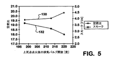
図5は、エンジンクランクシャフト回転角度で測定した如き、空燃比と、エンジンサイクル中の排気バルブが開き始める時期との関係を定めるプロット130を有する。図5は又、スモークと、排気バルブが開き始める時期との関係を定める第2のプロット132を有する。図5は、排気バルブ開放の始まりをますます遅らせることによって生じた増大したターボチャージャー昇圧の結果、空燃比が増大し、スモークが減少することを示す。
【0031】
図6は、エンジンクランクシャフト回転角度で測定した如き、正味燃料消費率(BSFC)と、エンジンサイクル中の排気バルブが開き始める時間との関係を定めるプロット140を有する。図6は又、エンジントルクと、排気バルブが開き始める時間との関係を定める第2のプロット142を有する。図6は、図5で示された有用な利点が、増大したエンジンポンピングロスによって生じる増大した燃料消費及び減少したエンジントルクを犠牲にして来ることを示す。
【0032】
しかしながら、スモークの減少によって、追加の燃料供給をエンジンに行うことが出来る。図7、8及び9は、エンジンクランクシャフト回転角度で測定した如き、エンジントルク、ターボチャージャー速度、空気流量、スモーク、出力(馬力)及びテールパイプ温度即ち排気管温度のそれぞれと、エンジンサイクル中の排気バルブが開き始める時期との関係を定める6つのプロット150、152、160、162、170及び172を有する。それらの関係は、同じ一定の燃料供給下で得られる。それらは、排気バルブ開放の始まりを基準(この場合では、135度ATDC(上死点後)付近)から遅延させることが、ターボチャージャー速度の増大を伴うポイントまでトルクを増大させることを示す。その後、ターボチャージャー速度が増大し続けるとき、トルクはわずかに下がる。
【0033】
ますます遅延される排気バルブ開放の始まりの結果としてトルクが増大し始めるポイントでは、排気エネルギが、ターボチャージャーによってより効率的に使用され、ターボチャージャー速度をなおいっそう増大させる。その結果増大した昇圧は、空気流量を増大させる。スモークは、排気バルブが開く前のシリンダ内部での長い燃焼時間及びより大きい空燃比によって減少する。
【0034】
図10は、排気バルブ開放の始まりの増大した遅延での、過燃料供給パーセントの関数としてのエンジントルクのプロット180、及び、過燃料供給パーセントの関数としてのスモークのプロット182を示す。基準スモークと同じスモークエミッションについて、図10は、遅延によって30%のより多い燃料をエンジンに追加することが出来、その結果、エンジントルクも同様に増大する、ことを示す。
【0035】
図11は、排気バルブ開放の始まりの4つの異なるタイミングについて、エンジンクランクシャフト角度に対する排気圧力の4つの軌跡190、192、194及び196を示す。軌跡190は、基準タイミングについて、エンジンクランクシャフト角度に対する排気圧力を示す。軌跡192は、進められたタイミングについて、エンジンクランクシャフト角度に対する排気圧力を示す。軌跡194は、遅延されたタイミングについて、エンジンクランクシャフト角度に対する排気圧力を示す。軌跡196は、過大に遅延されたタイミングについて、エンジンカムシャフト角度に対する排気圧力を示す。
【0036】
シリンダーからの排気のプロセスは、上述したブローダウン段階及びポンプアウト段階を仮定している。タイミングが、基準タイミングから進められると、軌跡192を軌跡190と比べることで分かるように、エネルギが排気ガスに付加され、かくして、ターボチャージャー速度は増大する。エネルギが、圧力が既に増大している排気圧力脈動の立上がりのきわに付加されるので、ターボチャージャーにとって、エネルギ使用はより低効率のものである。エネルギは、エンジンから奪われ、かくして、エンジントルクは減少する。
【0037】
タイミングが、基準タイミングから遅延されると、軌跡194を軌跡190と比べることで分かるように、ブローダウン段階からポンプアウト段階まで排気圧力の平滑な移行が現れる。ターボチャージャーにとって、これは、排気エネルギのより効率的な使用を意味する。さらに、遅延された排気バルブ開放の始まりが、ブローダウンを排気ストロークまで延ばすので、エンジンシリンダ内の上昇ストローク中のピストンは、ブローダウン期間の圧力降下をゆっくりにする。エンジンにとって、これは、ピストンがより高いガス圧力に抗して働くので追加のポンピングロスを意味する。それにもかかわらず、膨脹仕事量は、ポンピングロスより勝り、従って、トルク出力は増大し、且つ、ついには、最小の正味燃料消費率(BSFC)で最大のトルク出力を得るのに最適な排気バルブ開放の始まりを示すピークに達する。タービンについては、これは、図7乃至9に示すように、増大したターボチャージャー速度、昇圧圧力及び吸気流量をもたらす付加的なエネルギを意味する。エネルギが、圧力脈動の落ち込みのきわに付加されると、ターボチャージャーにとって、エネルギ使用は高効率のものとなる。
【0038】
タイミングが、基準タイミングに対して過大に遅延されると、軌跡196を軌跡190と比べることで分かるように、ポンピングロスが仕事量に勝り、エンジントルクが、落ち込み始める。ターボチャージャー速度が増大し続けると、同じように吸入空気流量が増大する。これは、エンジンへのポンピングロスが、排気に付加されるエネルギになり、軌跡196の広げられ且つより高い排気圧脈動として反映される。不十分な吸入空気質量による低いエンジン速度での発煙限界(smoke limiting)によって、排気バルブ開放の始まりの過大な遅延は、よりたくさんの空気をもたらし、かくして、トルク向上のためのより過大な燃料供給を可能にする。言い換えれば、過大な遅延によってトルク向上の可能性があるが、そのようなトルク増加は、上述したように、正味燃料消費率(BSFC)を最小にする一方トルクを最大にする最適な遅延と比べると、BSFCの増大を伴う。
【0039】
本発明の現時点で好ましい実施形態を図示すると共に説明してきたが、本発明の原理は、全ての実施形態に適用可能であり、且つ、特許請求の範囲内で使用することが認識されるであろう。
【図面の簡単な説明】
【0040】
【図1】本発明の原理によるエンジンの全体略線図である。
【図2】本発明を実施するのに使用されるアルゴリズムの流れ線図である。
【図3】本発明を理解するのに有用なグラフである。
【図4】本発明を理解するのに有用なグラフである。
【図5】本発明を理解するのに有用なグラフである。
【図6】本発明を理解するのに有用なグラフである。
【図7】本発明を理解するのに有用なグラフである。
【図8】本発明を理解するのに有用なグラフである。
【図9】本発明を理解するのに有用なグラフである。
【図10】本発明を理解するのに有用なグラフである。
【図11】本発明を理解するのに有用なグラフである。【Technical field】
[0001]
The present invention relates generally to a supercharged diesel engine for propelling a motor vehicle and having a variable bubble actuation device, and in particular to an exhaust such as a diesel engine exhaust smoke, especially at relatively low boost pressure engine speeds. A control strategy for increasing engine torque without undesired consequences for tube emissions.
[Background Art]
[0002]
Turbochargers are one of the devices used to supercharge internal combustion engines. Diesel engines supercharged by turbochargers are sometimes referred to as turbocharged diesels. The turbocharger comprises a turbine, which is operated by the exhaust gas and is connected to a shaft that operates a compressor, which increases the pressure of the engine intake system downstream thereof. Boosting is controlled by controlling turbine operation.
[0003]
Strategies for controlling turbine operation must take into account the particular type of turbocharger. Certain types of turbochargers have a variable geometry, i.e., a variable nozzle, that can change the manner in which exhaust gas flowing through the turbocharger interacts with the turbine. The movable vanes are selectively positioned to control the characteristics of the interaction of the exhaust gas with the turbine, and therefore to control the boost. The turbocharger has an electromechanical actuator for connecting the electric control device and the movable vane. The actuator comprises a solenoid for setting a vane position according to a control signal from an electric control device. The control signal is created according to the desired control strategy.
[0004]
A wastegate turbocharger controls the proportion of exhaust gas that interacts with the turbine by controlling the degree to which a wastegate valve that allows exhaust gas to escape from the turbine is opened. The wastegate valve may be actuated by an electric actuator to which a control signal is applied.
[0005]
It is believed that turbochargers are generally considered devices for improving engine performance. The amount of engine exhaust utilized to operate the turbocharger turbine at low engine speeds is sufficient to enable boosting in order for the turbocharger compressor to contribute to improved performance at such low speeds. Turbochargers are typically designed for higher engine speeds, as they are usually insufficient to generate a boost.
DISCLOSURE OF THE INVENTION
[Problems to be solved by the invention]
[0006]
However, some turbocharged diesel engines, especially those with variable valve timing, can produce high low speed torque without the undesirable consequences of exhaust pipe emissions such as smoke in engine exhaust. Was found. This remedy is achieved by (1) the time the engine exhaust valve opens during the engine operating cycle, and (2) certain related controls on the engine fuel supply. In general, related controls include retarding the opening of the exhaust valve while increasing the fuel supply to maintain a desired air-fuel ratio in the combustion chamber. The remedy can result in a significant increase in engine torque during low speed operation of the engine without significantly affecting exhaust pipe emissions.
[0007]
The process of exhausting combustion products from the combustion chamber of a diesel engine includes: (1) a blow-down phase in which the exhaust gas pressure is large enough to cause exhaust gas flow to an open exhaust valve; (2) a running engine mechanism. Is considered to include two stages: a pump-out stage in which the discharge volume of the combustion space is reduced to the extent that the exhaust gas is pushed out of an open exhaust valve. The blow down phase begins as soon as the exhaust valve is opened, while the pump out phase occurs later. For example, if the exhaust valve of the engine cylinder is opened when the piston completes a power down stroke in the cylinder prior to the arrival of the piston at bottom dead center (BDC), the blowdown phase will occur before the BDC. Begin. The blowdown phase may also be exhausted until the pressure drops to an insufficient degree to cause continued exhaust flow, or the piston on the upstroke may create enough pressure to push exhaust gas from the open exhaust valve. Continue with the next exhaust upstroke of the piston until the volume is reduced. Delaying the timing of opening the exhaust valve is beneficial to turbocharger operation, especially at low engine speeds that were previously considered relatively inefficient by turbochargers to improve engine performance. Test results show that a typical exhaust blowdown can be created.
[0008]
Since one principle of the present invention involves varying when the exhaust valves open during the engine operating cycle, the engine must have a suitable mechanism for each exhaust valve. Examples of such mechanisms include an electric actuator for opening and closing an exhaust valve in response to an applied electrical signal. Such engines are often referred to as camless engines, especially when the engine intake valves are also controlled by electric actuators. As creative strategies are appealed, the timing of opening each exhaust valve during an engine cycle is increasingly delayed.
[0009]
By delaying exhaust valve opening, the in-cylinder burn time of particulates is increased, which reduces particulate emissions. Delaying exhaust valve opening has also been found to provide increased energy input to the turbocharger compressor, thereby increasing boost, a finding contrary to current mainstream knowledge. As fuel pressure increases and smoke decreases, additional fueling is not detrimental to exhaust emissions at all, as engine fueling is also increased, producing increased engine torque. In this way, the turbocharger is forced to operate at its performance limits, thereby allowing the engine to produce a corresponding torque that is greater than would otherwise be achieved.
[0010]
However, delaying the opening of the exhaust valve in connection with increasing engine fueling will affect turbocharger operation. One possible result is the undesirable surging of the turbocharger compressor that may occur if the exhaust flow acting on the turbine forces the turbocharger to operate beyond its performance limits. To avoid such surging, a bleed valve at the outlet of the compressor operates at or in anticipation of the initial compressor surging to block or prevent compressed charge air from initial surging. Release enough from the intake system. The compressed charge air is discharged from the intake system to increase the intake manifold pressure without turbocharger surging. Because of this ability to achieve increased intake manifold pressure without turbocharger surging, the turbocharger can be operated at or near its performance limits even at low engine speeds, and the principles of the present invention There is no need to modify or change the basic structure of a turbocharger, which is typically designed for high speed rather than low speed operation. The association between the bleed valve and the engine intake system, which releases compressed charge air from the intake system, is probably sufficient with the addition of sensors or by incorporating appropriate algorithms into the engine control processor.
[Means for Solving the Problems]
[0011]
A major aspect of the present invention relates to a novel strategy for controlling exhaust valve opening of a turbo diesel engine having a variable valve actuator. When the engine is operating at a lower speed than the peak torque speed, the engine control system causes the exhaust valve to open later in the engine cycle than in an engine having a camshaft that operates the exhaust valve. The extent to which the control system delays opening the exhaust valve is a function of one or more selected variables such as engine speed, engine load, boost, net fuel consumption (BSFC), and vehicle acceleration.
[0012]
One aspect of the invention relates to a novel strategy for a supercharged internal combustion engine, in particular a supercharged compression ignition or diesel engine with variable valve actuation. The disclosed strategy is implemented by engine control by a processor and utilizes data regarding certain engine operating parameters that control the release (bleed) of compressed charge air from the engine intake system. The data is processed according to a software algorithm executed by a processor to generate data for control signals applied to an electrically actuated bleed valve at the outlet of the compressor of the turbocharger. Controlled release prevents any initial surging of the turbocharger resulting from an increasingly delayed opening of the exhaust valve and associated with increased fuel supply.
[0013]
One aspect of the claimed invention relates to an internal combustion engine having an intake system including a turbocharger, wherein the charge air is delivered through the intake system to an intake manifold of the engine, the turbocharger comprising: It has a compressor that is operated by exhaust gas from the engine and that produces compressed charge air that provides a boost in the intake manifold. A discharge device that discharges some of the compressed charge air from the intake manifold increases the intake manifold pressure without turbocharger compressor surging. The control device controls opening of the engine exhaust valve for the engine operation cycle, fuel supply of the engine for the engine operation cycle, and a bleed device. Occasionally, the controller will more and more delay the exhaust valve opening on the engine working cycle and increase the engine fuel supply on the increased intake manifold pressure, such that the turbocharger will increase the intake manifold pressure, and such an increasing delay In response to any initial surging of the compressor resulting from the effect of the exhaust valve opening and such increased engine fuel supply on the engine exhaust, the bleed device is actuated to prevent such compressor surging. .
[0014]
Other general aspects of the claimed invention relate to a method for an engine as described below, wherein the method occasionally delays the opening of the exhaust valve with respect to the engine operating cycle. Having the turbocharger increase the intake manifold pressure, increasing the engine fuel supply with respect to the increased intake manifold pressure, such an increasingly delayed exhaust valve opening and engine exhaust of such increased engine fuel supply A method of activating the bleed device in response to any initial surging of the compressor resulting from its effect on the gas to prevent such surging of the compressor.
[0015]
A further aspect of the claimed invention relates to a software algorithm implemented in an engine control processor to accomplish the method described above.
[0016]
The features and advantages described above, together with further aspects of the invention, will be apparent from the disclosure of the presently preferred embodiment of the invention, which represents the best mode currently contemplated for carrying out the invention. This description includes the drawings and the detailed description with reference to these drawings.
BEST MODE FOR CARRYING OUT THE INVENTION
[0017]
FIG. 1 shows an internal combustion engine (engine) 10 that supplies power to an automobile. An example of such a vehicle is a chassis in which the
[0018]
The
[0019]
[0020]
An engine
[0021]
The supercharging of the
[0022]
The
[0023]
[0024]
When executed, the
[0025]
In a
[0026]
However, sometime the delay will be sufficient to cause turbocharger surging. Therefore, if
[0027]
Once such a determination has been made, the algorithm returns to step 54.
[0028]
FIG. 3 shows an example of a known turbocharger compressor speed map. A
[0029]
FIG. 4 has a
[0030]
FIG. 5 has a
[0031]
FIG. 6 has a
[0032]
However, due to reduced smoke, additional fueling can be provided to the engine. FIGS. 7, 8 and 9 show engine torque, turbocharger speed, air flow, smoke, power (hp) and tailpipe or exhaust pipe temperature, respectively, as measured in engine crankshaft rotation angle, and during the engine cycle. There are six
[0033]
At the point where the torque begins to increase as a result of the increasingly delayed onset of exhaust valve opening, exhaust energy is used more efficiently by the turbocharger, further increasing turbocharger speed. The resulting increased pressure increases the air flow. Smoke is reduced due to the long combustion time inside the cylinder before the exhaust valve opens and the higher air-fuel ratio.
[0034]
FIG. 10 shows a
[0035]
FIG. 11 shows four
[0036]
The process of evacuating the cylinder assumes the blow-down and pump-out phases described above. As the timing advances from the reference timing, energy is added to the exhaust gas, as can be seen by comparing
[0037]
If the timing is delayed from the reference timing, a smooth transition of the exhaust pressure appears from the blowdown stage to the pumpout stage, as can be seen by comparing the
[0038]
If the timing is excessively delayed with respect to the reference timing, as can be seen by comparing
[0039]
While the presently preferred embodiments of the invention have been illustrated and described, it will be appreciated that the principles of the invention are applicable to all embodiments and may be used within the scope of the claims. Would.
[Brief description of the drawings]
[0040]
FIG. 1 is an overall schematic diagram of an engine according to the principles of the present invention.
FIG. 2 is a flow diagram of the algorithm used to implement the present invention.
FIG. 3 is a graph useful for understanding the present invention.
FIG. 4 is a graph useful for understanding the present invention.
FIG. 5 is a graph useful for understanding the present invention.
FIG. 6 is a graph useful for understanding the present invention.
FIG. 7 is a graph useful for understanding the present invention.
FIG. 8 is a graph useful for understanding the present invention.
FIG. 9 is a graph useful for understanding the present invention.
FIG. 10 is a graph useful for understanding the present invention.
FIG. 11 is a graph useful for understanding the present invention.
Claims (13)
圧縮装填空気のいくらかを放出するためのブリード装置と、
通常は閉じられ、排気ガスがエンジンの燃焼室を出るために開放する排気バルブと、
エンジン作動サイクルに関して排気バルブの開放を制御するための、エンジン作動サイクルに関してエンジンの燃料供給を制御するための、そして、ブリード装置を制御するための制御装置と、を有する内燃機関であって、
折々、制御装置は、ターボチャージャーが吸気マニホールド内の圧力を増大させるように、エンジン作動サイクルに関して排気バルブ開放をますます遅延させ、吸気マニホールドの増大した圧力に関してエンジン燃料供給を増大させ、そのようなますます遅延した排気バルブ開放及びそのような増大したエンジン燃料供給から生じる圧縮機のどんな初期サージングにも応答して、ブリード装置を作動してそのような圧縮機サージングを妨げる、内燃機関。An intake system for delivering charge air to the intake manifold of the engine, including a turbocharger activated by exhaust gas from the engine and having a compressor for delivering compressed charge air into the intake manifold;
A bleed device for discharging some of the compressed charge air;
An exhaust valve that is normally closed and opens to allow exhaust gases to exit the combustion chamber of the engine;
A control device for controlling opening of an exhaust valve with respect to the engine operating cycle, for controlling fueling of the engine with respect to the engine operating cycle, and for controlling a bleed device, comprising:
Occasionally, the controller will increasingly delay the exhaust valve opening with respect to the engine operating cycle so that the turbocharger will increase the pressure in the intake manifold, and will increase the engine fuel supply with respect to the increased intake manifold pressure, An internal combustion engine that operates a bleed device to prevent such compressor surging in response to an increasingly delayed exhaust valve opening and any initial surging of the compressor resulting from such increased engine fueling.
圧縮装填空気のいくらかを放出するためのブリード装置と、
通常は閉じられ、排気ガスがエンジンの燃焼室を出るために開放する排気バルブと、を有する内燃機関を作動する方法であって、
折々、エンジン作動サイクルに関して排気バルブ開放をますます遅らせてターボチャージャーにより吸気マニホールド内の圧力を増大させるステップと、
増大した吸気マニホールドの圧力に関してエンジン燃料供給を増大させるステップと、
そのようなますます遅延した排気バルブ開放及びそのような増大したエンジン燃料供給の、エンジン排気ガスから生じる圧縮機のどんな初期サージングにも応答して、ブリード装置を作動してそのような圧縮機サージングを妨げるステップと、を有する方法。An intake system for delivering charge air to the intake manifold of the engine, including a turbocharger activated by exhaust gas from the engine and having a compressor for delivering compressed charge air into the intake manifold;
A bleed device for discharging some of the compressed charge air;
An exhaust valve which is normally closed and opens to allow exhaust gases to exit the combustion chamber of the engine, comprising:
Occasionally increasing the pressure in the intake manifold by a turbocharger with an increasingly delayed opening of the exhaust valve with respect to the engine operating cycle;
Increasing the engine fuel supply with respect to the increased intake manifold pressure;
In response to any initial surging of the compressor resulting from engine exhaust, such an increasingly delayed exhaust valve opening and such an increased engine fuel supply, the bleed device is activated to activate such compressor surging. Interfering with the method.
エンジン作動サイクルに関して排気バルブ開放をますます遅延させてターボチャージャーにより吸気マニホールド圧力を増大させるステップは、排気バルブ開放の遅延をエンジン作動サイクルにおける一定度数だけ増大させるステップを有し、
増大した吸気マニホールド内の圧力に関してエンジン燃料供給を増大させるステップは、圧縮機が排気バルブ開放の増大した遅延に応答してサージし始めなかったならば、エンジン燃料供給をいくらかの量だけ増大させるステップを有する、請求項8記載の方法。The engine operating cycle has a compression ignition operating cycle,
Increasing the intake manifold pressure with the turbocharger by increasingly delaying the exhaust valve opening with respect to the engine operating cycle comprises increasing the exhaust valve opening delay by a certain number in the engine operating cycle.
Increasing the engine fuel supply with respect to the increased intake manifold pressure comprises increasing the engine fuel supply by some amount if the compressor did not begin to surge in response to the increased delay of exhaust valve opening. 9. The method of claim 8, comprising:
Applications Claiming Priority (2)
| Application Number | Priority Date | Filing Date | Title |
|---|---|---|---|
| US09/906,487 US6434938B1 (en) | 2001-07-16 | 2001-07-16 | Control strategy for turbocharged engine having variable valve actuation apparatus |
| PCT/US2002/020578 WO2003008787A1 (en) | 2001-07-16 | 2002-06-27 | Control strategy for turbocharged engine having variable valve actuation apparatus |
Publications (2)
| Publication Number | Publication Date |
|---|---|
| JP2004536253A true JP2004536253A (en) | 2004-12-02 |
| JP4194937B2 JP4194937B2 (en) | 2008-12-10 |
Family
ID=25422520
Family Applications (1)
| Application Number | Title | Priority Date | Filing Date |
|---|---|---|---|
| JP2003514103A Expired - Fee Related JP4194937B2 (en) | 2001-07-16 | 2002-06-27 | Control strategy for turbocharged engines with variable valve actuators |
Country Status (11)
| Country | Link |
|---|---|
| US (1) | US6434938B1 (en) |
| EP (1) | EP1415076B1 (en) |
| JP (1) | JP4194937B2 (en) |
| KR (1) | KR100881467B1 (en) |
| CN (1) | CN1298981C (en) |
| AT (1) | ATE333580T1 (en) |
| BR (1) | BR0211134B1 (en) |
| CA (1) | CA2452042C (en) |
| DE (1) | DE60213251T2 (en) |
| MX (1) | MXPA04000047A (en) |
| WO (1) | WO2003008787A1 (en) |
Cited By (1)
| Publication number | Priority date | Publication date | Assignee | Title |
|---|---|---|---|---|
| JP2004044594A (en) * | 2002-07-09 | 2004-02-12 | Waertsilae Schweiz Ag | Operating method of reciprocating internal combustion engine |
Families Citing this family (16)
| Publication number | Priority date | Publication date | Assignee | Title |
|---|---|---|---|---|
| US6658845B1 (en) | 2002-08-20 | 2003-12-09 | International Engine Intellectual Property Company, Llc | Control strategy using variable valve actuation to reduce particulate emission and improve driveability during transient operation of a turbocharged diesel engine |
| US6647723B1 (en) | 2002-08-20 | 2003-11-18 | International Engine Intellectual Property Company, Llc | Control strategy for counteracting incipient turbocharger surging using a variable valve actuation mechanism for through-cylinder bleed |
| US6945047B2 (en) * | 2002-10-21 | 2005-09-20 | General Electric Company | Apparatus and method for automatic detection and avoidance of turbocharger surge on locomotive diesel engines |
| DE102004035575A1 (en) * | 2004-07-22 | 2006-02-16 | Daimlerchrysler Ag | Method and device for controlling an internal combustion engine with a compressor, in particular an exhaust gas turbocharger |
| US7167792B1 (en) | 2006-01-23 | 2007-01-23 | Ford Global Technologies, Llc | Method for stopping and starting an internal combustion engine having a variable event valvetrain |
| US7562530B2 (en) * | 2006-04-05 | 2009-07-21 | Ford Global Technologies, Llc | Method for controlling an internal combustion engine having a variable event valvetrain |
| US7458346B2 (en) * | 2006-04-05 | 2008-12-02 | Ford Global Technologies, Llc | Method for controlling valves of an engine having a variable event valvetrain during an engine stop |
| US7621126B2 (en) * | 2006-04-05 | 2009-11-24 | Ford Global Technoloigies, LLC | Method for controlling cylinder air charge for a turbo charged engine having variable event valve actuators |
| US20080078176A1 (en) * | 2006-10-02 | 2008-04-03 | International Engine Intellectual Property Company | Strategy for control of recirculated exhaust gas to null turbocharger boost error |
| US8448626B2 (en) * | 2008-08-13 | 2013-05-28 | International Engine Intellectual Property Company, Llc | Exhaust system for engine braking |
| US8136357B2 (en) | 2008-08-27 | 2012-03-20 | Honda Motor Co., Ltd. | Turbocharged engine using an air bypass valve |
| US8307646B2 (en) * | 2009-08-04 | 2012-11-13 | International Engine Intellectual Property Company, Llc | System using supplemental compressor for EGR |
| US8635856B2 (en) * | 2010-02-12 | 2014-01-28 | International Engine Intellectual Property Company, Llc | System for disabling diesel particulate filter regeneration during electric operation |
| JP6431018B2 (en) * | 2016-10-24 | 2018-11-28 | 本田技研工業株式会社 | Control device for internal combustion engine |
| CN107178418B (en) * | 2017-06-06 | 2019-09-17 | 天津大学 | Preprocessor heat management control method based on air inlet system and exhaust system |
| US10859055B1 (en) * | 2019-08-26 | 2020-12-08 | Ford Global Technologies, Llc | Method for starting an engine |
Family Cites Families (14)
| Publication number | Priority date | Publication date | Assignee | Title |
|---|---|---|---|---|
| DE1751061C3 (en) * | 1968-03-27 | 1974-07-04 | Michael Dipl.-Ing. Rolle May (Schweiz) | Externally ignited internal combustion engine charged by means of an exhaust gas turbocharger |
| US4485625A (en) * | 1981-04-15 | 1984-12-04 | Toyo Kogyo Co., Ltd. | Control means for internal combustion engines |
| DE3506106A1 (en) * | 1984-02-22 | 1985-08-22 | Audi AG, 8070 Ingolstadt | Method for controlling the power output of an exhaust turbocharger supplying a valve-timed internal combustion engine |
| WO1988008486A1 (en) * | 1987-04-20 | 1988-11-03 | Allied-Signal Inc. | Closed loop turbocharger control system with transient wastegate control |
| DE3714192A1 (en) * | 1987-04-29 | 1988-11-10 | Bosch Gmbh Robert | Method of controlling an exhaust turbocharger |
| US5187935A (en) * | 1988-12-26 | 1993-02-23 | Honda Giken Kogyo Kabushiki Kaisha | Engine control device |
| JP2741266B2 (en) * | 1989-12-18 | 1998-04-15 | マツダ株式会社 | Engine intake and exhaust control device |
| DE4439573A1 (en) * | 1994-11-05 | 1996-05-09 | Mtu Friedrichshafen Gmbh | Method of using IC engine |
| DE4445411A1 (en) * | 1994-12-20 | 1996-06-27 | Opel Adam Ag | Internal combustion engine |
| ATE209299T1 (en) | 1995-08-04 | 2001-12-15 | Jenbacher Ag | DEVICE FOR CONTROLLING AN ENGINE SIZE, IN PARTICULAR THE POWER OR SPEED OF AN COMBUSTION ENGINE |
| US20010045194A1 (en) * | 1998-04-02 | 2001-11-29 | Takuya Shiraishi | Internal combustion engine control system |
| WO1997013063A1 (en) * | 1995-10-02 | 1997-04-10 | Hitachi, Ltd. | Control device for an internal combustion engine |
| JP3926522B2 (en) * | 1999-09-20 | 2007-06-06 | 株式会社日立製作所 | Intake control device for turbocharged engine |
| US6295816B1 (en) * | 2000-05-24 | 2001-10-02 | General Electric Company | Turbo-charged engine combustion chamber pressure protection apparatus and method |
-
2001
- 2001-07-16 US US09/906,487 patent/US6434938B1/en not_active Expired - Lifetime
-
2002
- 2002-06-27 MX MXPA04000047A patent/MXPA04000047A/en active IP Right Grant
- 2002-06-27 CN CNB028142640A patent/CN1298981C/en not_active Expired - Lifetime
- 2002-06-27 EP EP02744730A patent/EP1415076B1/en not_active Expired - Lifetime
- 2002-06-27 CA CA002452042A patent/CA2452042C/en not_active Expired - Fee Related
- 2002-06-27 AT AT02744730T patent/ATE333580T1/en active
- 2002-06-27 DE DE60213251T patent/DE60213251T2/en not_active Expired - Lifetime
- 2002-06-27 KR KR1020047000550A patent/KR100881467B1/en not_active Expired - Fee Related
- 2002-06-27 JP JP2003514103A patent/JP4194937B2/en not_active Expired - Fee Related
- 2002-06-27 WO PCT/US2002/020578 patent/WO2003008787A1/en not_active Ceased
- 2002-06-27 BR BRPI0211134-9A patent/BR0211134B1/en not_active IP Right Cessation
Cited By (1)
| Publication number | Priority date | Publication date | Assignee | Title |
|---|---|---|---|---|
| JP2004044594A (en) * | 2002-07-09 | 2004-02-12 | Waertsilae Schweiz Ag | Operating method of reciprocating internal combustion engine |
Also Published As
| Publication number | Publication date |
|---|---|
| CA2452042A1 (en) | 2003-01-30 |
| US6434938B1 (en) | 2002-08-20 |
| BR0211134A (en) | 2004-12-14 |
| DE60213251D1 (en) | 2006-08-31 |
| CA2452042C (en) | 2006-06-20 |
| BR0211134B1 (en) | 2011-09-20 |
| EP1415076A1 (en) | 2004-05-06 |
| EP1415076A4 (en) | 2005-10-12 |
| CN1537195A (en) | 2004-10-13 |
| ATE333580T1 (en) | 2006-08-15 |
| EP1415076B1 (en) | 2006-07-19 |
| CN1298981C (en) | 2007-02-07 |
| JP4194937B2 (en) | 2008-12-10 |
| MXPA04000047A (en) | 2004-05-21 |
| KR100881467B1 (en) | 2009-02-05 |
| KR20040019062A (en) | 2004-03-04 |
| WO2003008787A1 (en) | 2003-01-30 |
| DE60213251T2 (en) | 2007-07-19 |
Similar Documents
| Publication | Publication Date | Title |
|---|---|---|
| JP4512617B2 (en) | Control device and method for internal combustion engine | |
| JP4194937B2 (en) | Control strategy for turbocharged engines with variable valve actuators | |
| EP1878895A2 (en) | Control of supercharged engine | |
| CN104975963B (en) | For the method with cylinder deactivation and the turbocharged engine of variable valve timing | |
| CN105324569B (en) | Engine controller | |
| EP1705358B1 (en) | Internal combustion engine and method for performing a mode switch in said engine | |
| US9689305B2 (en) | Method for operating a spark ignition internal combustion engine with an exhaust gas turbocharger | |
| GB2507061A (en) | Method of two-stage turbocharger matching for supporting cylinder deactivation. | |
| RU2511878C2 (en) | Control method of piston engine turbo-supercharger rotation frequency and control system for piston turbo-charged engine | |
| US6647723B1 (en) | Control strategy for counteracting incipient turbocharger surging using a variable valve actuation mechanism for through-cylinder bleed | |
| JP4007073B2 (en) | Turbocharged engine | |
| CN101611220A (en) | Control devices for internal combustion engines | |
| RU2633298C2 (en) | Operation method of turbocharger (versions) | |
| JP6914591B2 (en) | Internal combustion engine control device | |
| EP1239130B1 (en) | Dual-mode engine with controlled auto-ignition | |
| JP2000205055A (en) | Control device for engine with turbocharger | |
| JP2010043579A (en) | Internal combustion engine with turbocharger | |
| CN208982166U (en) | Improve the engine of responding ability | |
| CN109209623A (en) | Improve the engine of responding ability | |
| JPS58167823A (en) | Diesel engine with supercharger | |
| JP2017044173A (en) | Control device for internal combustion engine | |
| US8943822B2 (en) | Engine system having dedicated auxiliary connection to cylinder | |
| JP2012225232A (en) | Control device of internal combustion engine | |
| KR820000757B1 (en) | Method for improving the efficiency of internal combustion engines | |
| JP2016061248A (en) | Internal combustion engine and control method for internal combustion engine |
Legal Events
| Date | Code | Title | Description |
|---|---|---|---|
| A621 | Written request for application examination |
Free format text: JAPANESE INTERMEDIATE CODE: A621 Effective date: 20050310 |
|
| A131 | Notification of reasons for refusal |
Free format text: JAPANESE INTERMEDIATE CODE: A131 Effective date: 20070618 |
|
| A521 | Request for written amendment filed |
Free format text: JAPANESE INTERMEDIATE CODE: A523 Effective date: 20070914 |
|
| A131 | Notification of reasons for refusal |
Free format text: JAPANESE INTERMEDIATE CODE: A131 Effective date: 20080115 |
|
| A521 | Request for written amendment filed |
Free format text: JAPANESE INTERMEDIATE CODE: A523 Effective date: 20080414 |
|
| TRDD | Decision of grant or rejection written | ||
| A01 | Written decision to grant a patent or to grant a registration (utility model) |
Free format text: JAPANESE INTERMEDIATE CODE: A01 Effective date: 20080825 |
|
| A01 | Written decision to grant a patent or to grant a registration (utility model) |
Free format text: JAPANESE INTERMEDIATE CODE: A01 |
|
| A61 | First payment of annual fees (during grant procedure) |
Free format text: JAPANESE INTERMEDIATE CODE: A61 Effective date: 20080924 |
|
| R150 | Certificate of patent or registration of utility model |
Free format text: JAPANESE INTERMEDIATE CODE: R150 |
|
| FPAY | Renewal fee payment (event date is renewal date of database) |
Free format text: PAYMENT UNTIL: 20111003 Year of fee payment: 3 |
|
| FPAY | Renewal fee payment (event date is renewal date of database) |
Free format text: PAYMENT UNTIL: 20121003 Year of fee payment: 4 |
|
| FPAY | Renewal fee payment (event date is renewal date of database) |
Free format text: PAYMENT UNTIL: 20131003 Year of fee payment: 5 |
|
| R250 | Receipt of annual fees |
Free format text: JAPANESE INTERMEDIATE CODE: R250 |
|
| LAPS | Cancellation because of no payment of annual fees |