JP2004276802A - Anti-theft device - Google Patents
Anti-theft device Download PDFInfo
- Publication number
- JP2004276802A JP2004276802A JP2003072504A JP2003072504A JP2004276802A JP 2004276802 A JP2004276802 A JP 2004276802A JP 2003072504 A JP2003072504 A JP 2003072504A JP 2003072504 A JP2003072504 A JP 2003072504A JP 2004276802 A JP2004276802 A JP 2004276802A
- Authority
- JP
- Japan
- Prior art keywords
- vehicle
- portable device
- abnormality
- signal
- night
- Prior art date
- Legal status (The legal status is an assumption and is not a legal conclusion. Google has not performed a legal analysis and makes no representation as to the accuracy of the status listed.)
- Pending
Links
Images


Landscapes
- Burglar Alarm Systems (AREA)
- Alarm Systems (AREA)
Abstract
Description
【0001】
【発明の属する技術分野】
本発明は、異常が検出されるとそのことを車両側から受信して使用者に知らせる携帯機の消費電流を抑制する盗難防止装置の技術分野に属する。
【0002】
【従来の技術】
従来の盗難防止装置は、携帯機が間欠的に受信することで携帯機の消費電流を抑制し、電源となる電池の長寿命化を行っている(例えば、特許文献1参照。)。
【0003】
【特許文献1】
特開平11−20616号公報(第2−4頁、第5図)
【0004】
【発明が解決しようとする課題】
しかしながら、従来の盗難防止装置では、携帯機に求められる電源電池の長寿命化に対して十分ではなかった。
【0005】
本発明は、上記問題点に着目してなされたもので、その目的とするところは、携帯機の電源電池の長寿命化ができる盗難防止装置を提供することにある。
【0006】
【課題を解決するための手段】
上記目的を達成するため、請求項1記載の発明では、車両の異常を検出する異常検出手段を設け、異常検出手段から信号を得て車両の状態を監視し、間欠的に信号を送信しかつ異常検出の際には即時に警報信号を携帯機に送信する車載ユニットを設け、車載ユニットからの送信信号を受信して警報信号の際には使用する人に警報する携帯機を設け、携帯機が内部電源を有するものである盗難防止装置において、時間情報を得るための時間検出手段を車載ユニットに設け、昼夜で送信及び受信の間隔を変えるようにしたことを特徴とする手段とした。
【0007】
請求項2記載の発明では、車載ユニットの昼間の送信間隔を夜間より長くし、車載ユニットが昼夜の切替信号を携帯機に送信して携帯機の昼夜のモードを切替えるようにし、携帯機の昼間の受信間隔を夜間より長くしたことを特徴とする手段とした。
【0008】
請求項3記載の発明では、異常を検出したことを車両の周囲に知らせるための防犯アラームを設け、昼間に異常を検出した際のみ防犯アラームを鳴らすようにしたことを特徴とする手段とした。
【0009】
請求項4記載の発明では、車載ユニットから携帯機に定期的に時間情報を送信して、送受信タイミングの同期を取るようにしたことを特徴とする手段とした。
【0010】
【発明の作用と効果】
請求項1記載の発明では、車載ユニットに設けた時間検出手段によって、昼夜で車載ユニットの間欠的な送信及び携帯機の受信の間欠的な受信の間隔を変えて、適切な時間間隔にして節電を行い、携帯機の消費電流を抑えて、携帯機の電源電池の長寿命化ができる。よって、電源電池の交換や充電の手間を減らし、より使用しやすく、かつ必要な時に電源切れを起さないようにでき、より安心して使用できる。
【0011】
請求項2記載の発明では、盗難が起きにくい昼間の、車載ユニットの送信間隔及び携帯機の受信間隔を夜間より長くすることによって、節電を行い、携帯機の消費電流を抑えて、携帯機の電源電池の長寿命化ができる。
【0012】
請求項3記載の発明では、昼間に異常を検出すると防犯アラームを鳴らす。昼間に防犯アラームを鳴らしても周囲への迷惑の度合い低く周囲の人に異常を検出したことを知らせることができる。さらに、夜間には、防犯アラームを鳴らさないようにして、周囲に迷惑を掛けずに使用できるようにする。
【0013】
請求項4記載の発明では、車載ユニットから携帯機に定期的に時間情報を送信して、送受信タイミングの同期を取るので、間欠的な送信及び受信の間隔を長くしても確実に送受信を行うことができる。
【0014】
【発明の実施の形態】
以下、本発明の盗難防止装置を実現する実施の形態を、請求項1,2,3,4に係る発明に対応する実施例に基づいて説明する。
【0015】
(実施例)
【0016】
まず、構成を説明する。
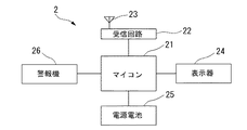
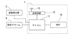
図1は実施例の盗難防止装置の車載ユニットのブロック図である。図2は実施例の盗難防止装置の携帯機のブロック図である。図3は実施例の盗難防止装置の昼夜の送受信タイミングを示す説明図である。図4は実施例の盗難防止装置の車載ユニットの制御部での警報に関する処理の流れを示すフローチャート図である。図5は実施例の車載ユニットの定期的な送信の処理の流れを示すフローチャートである。図6は実施例の盗難防止装置の携帯機の定期的な受信の処理の流れを示すフローチャートである。図1,2における主要符号を説明すると、1は車載ユニット、11はマイコン、12は送信回路、13はアンテナ、14は時計回路(時間検出手段)、2は携帯機、21はマイコン、22は受信回路、23はアンテナ、24は表示器、25は電源電池、26は警報機、3は異常検出器(異常検出手段)、4は防犯アラームである。
【0017】
本実施例では、盗難防止装置の車両ユニットを車両に搭載する。車載ユニット1には、使用する人が持つようにする携帯機2へ信号を送信するための送信回路12及びアンテナ13を設け、時間を計測する時計回路を設け、これらの制御を行うマイコン11を設ける。この車両には、異常検出器3を設ける。本実施例の異常検出器3は、認証なしにドアロックまたはドアを開けたことを検知するものであり、異常を検出した際には信号を発するものである。また、この車両には異常を検出した際に周囲に音で知らせる防犯アラーム4を設ける。防犯アラーム4は、車両のホーンを防犯アラーム4として用いるようにしてコストを抑制してもよいし、別のホーンを設けるようにしてもよい。
車両に設けた異常検出器3及び防犯アラーム4は車載ユニット1のマイコン11に接続する。
【0018】
次に使用する人が持つ携帯機2は、車載ユニット1からの信号を受信するための受信回路22及びアンテナ23を設け、使用する人に警報有無の状態を知らせるための表示器24を設け、異常検出の際に使用する人に音で知らせる警報機26を設け、これらの制御を行うマイコン21を設ける。また、携帯機2には電源電池25を設けるようにする。
【0019】
次に、作用を説明する。
【0020】
[車載ユニット1における異常監視の制御]
図4は実施例の盗難防止装置の車載ユニット1のマイコン11で実行される異常監視処理の流れを示すフローチャートで、以下、各ステップについて説明する。
【0021】
ステップS11では処理をスタートさせる。
【0022】
ステップS12では、使用する人の設定や操作により異常監視モードになっているかどうかを判断し、異常監視モードになっているならばステップS13に移行し、異常監視モードになっていないならばステップS17に移行する。
【0023】
ステップS13では、異常検出器3によって不正な動作でドアロックまたはドアが開けられたかどうかを判断し、不正にドアロックまたはドアが開けられたならばステップS14に移行し、不正にドアロックまたはドアが開けらていないならばステップS17に移行する。
【0024】
ステップS14では、時計回路からの時間情報によって昼間であるか夜間であるかを判断し、昼間であるならばステップS15に移行し、夜間であるならばステップS16に移行する。
【0025】
ステップS15では、防犯アラーム4を作動させて警報音を発させる。
【0026】
ステップS16では、送信回路12とアンテナ13により警報信号を携帯機2に発信する。
【0027】
ステップS17では、処理をリターンする。
【0028】
[車載ユニット1における昼夜モードの制御]
図5は実施例の盗難防止装置の車載ユニット1のマイコン11で実行される昼夜モード処理の流れを示すフローチャートで、以下、各ステップについて説明する。
【0029】
ステップS21では、処理をスタートさせる。
【0030】
ステップS22では、時計回路の時間情報によって昼間であるか夜間であるかを判断し、昼間であるならばステップS23に移行し、夜間であるならばステップS25に移行する。
【0031】
ステップS23では、図3(b)に示すように間欠的な送信時間のON時間をt2より短いt1にし、OFF時間をT2より長いT1にする。
【0032】
ステップS24では、設定を昼モードにした信号を携帯機2に送信する。
【0033】
ステップS25では、図3(a)に示すように間欠的な送信時間のON時間をt1より長いt2にし、OFF時間をT1より短いT2にする。
【0034】
ステップS26では、設定を夜モードにした信号を携帯機2に送信する。
【0035】
ステップS27では、処理をリターンする。
【0036】
[携帯機における昼夜モードの制御]
図6は実施例の盗難防止装置の携帯機2のマイコン21で実行される昼夜モードの処理の流れを示すフローチャートで、以下、各ステップについて説明する。
【0037】
ステップS31では、処理をスタートさせる。
【0038】
ステップS32では、昼間の設定となっている信号を受信したかどうかを判断し、受信したならばステップS33に移行し、受信しないならばステップS34に移行する。
【0039】
ステップS33では、間欠的な受信の間隔、つまりOFF時間をT’2より長いT’1に変更する。
【0040】
ステップS34では、夜間の設定となっている信号を受信したかどうかを判断し、受信したならばステップS35に移行し、受信しないならばステップS36に移行する。
【0041】
ステップS35では、間欠的な受信の間隔、つまりOFF時間をT’1より短いT’2に変更する。
【0042】
ステップS36では、処理をリターンする。
【0043】
[昼間の節電作用]
車載ユニット1のマイコン11では時計回路からの時間情報によりステップS22で昼間かどうかを判断する。昼間は不正にドアを開けて車内に入ろうとするものが人に見られやすいなどの理由から夜間より盗難されにくい。このため、昼間である場合には、図3(b)に示すように夜間より送信信号のON時間を夜間より短くするとともに送信信号の間隔つまりOFF時間を夜間より長くする。これにより車載ユニット1での消費電流を抑えることができる。
【0044】
さらに、車載ユニット1では昼間の設定を定期的にステップS24で携帯機2に送信する。携帯機2では、昼間の設定を受信すると図3(b)に示すように受信間隔つまりOFF時間を夜間より長くする。これにより、携帯機2の電源電池25の消費電流を抑えることができる。
【0045】
[送受信の同期作用]
ステップS24及びステップS26で行われる車載ユニット1から携帯機2への昼夜の設定の送信は定期的に行うようにする。この定期的な送信には時間情報を含むようにする。これにより、図3に示すように、昼間でも夜間でも送受信の信号を同期させる。
【0046】
[周囲への配慮作用]
不正なドアロックまたはドアの開きが検出されたならば、車載ユニット1は昼間かどうかをステップS14で判断し、昼間のみ防犯アラーム4を作動させる。昼間に不正な操作を行うものは、これにより周囲の人に気づかれる可能性が高まるとともに、不正な操作を止めるように警告できることとなる。
【0047】
一方、ステップS14の判断により夜間と判断された場合には、異常を検出しても防犯アラーム4を作動させないようにして、周囲への配慮を行うとともに、誤作動の際に周囲に迷惑をかけることがないようにする。
【0048】
実施例の盗難防止装置にあっては、下記に列挙する効果を得ることができる。
【0049】
(1)車両の異常を検出する異常検出器3を設け、異常検出器3から信号を得て車両の状態を監視し、間欠的に信号を送信しかつ異常検出の際には即時に警報信号を携帯機2に送信する車載ユニット1を設け、車載ユニット1からの送信信号を受信して警報信号の際には使用する人に警報する携帯機2を設け、携帯機2が内部に電源電池25を有するものである盗難防止装置において、時間情報を得るための時間回路14を車載ユニット1に設け、昼夜で送信及び受信の間隔を変えるようにしたため、昼間の携帯機2の消費電流を抑制して、携帯機2の電源電池25の長寿命化ができる。よって、電源電池25の交換や充電の手間を減らし、より使用しやすく、かつ必要な時に電源切れを起さないようにでき、より安心して使用できる。
【0050】
(2)車載ユニット1の昼間の送信間隔を夜間より長くし、車載ユニット1が昼夜の切替信号を携帯機2に送信して携帯機2の昼夜のモードを切替えるようにし、携帯機2の昼間の受信間隔を夜間より長くしたため、盗難が起きにくい昼間の節電を行い、携帯機2の消費電流を抑えて、携帯機2の電源電池25の長寿命化ができる。
【0051】
(3)異常を検出したことを車両の周囲に知らせるための防犯アラーム4を設け、昼間に異常を検出した際のみ防犯アラーム4を鳴らすようにしたため、周囲への迷惑の度合い低く異常を検出したことを知らせることができる。さらに、夜間には、防犯アラーム4を鳴らさないようにして、周囲に迷惑を掛けずに使用できるようにする。
【0052】
(4)車載ユニット1から携帯機2に定期的に時間情報を送信して、送受信タイミングの同期を取るようにしたため、確実に送受信を行うことができる。
【0053】
以上、本発明の盗難防止装置を実施例に基づき説明してきたが、具体的な構成については、これらの実施例に限られるものではなく、特許請求の範囲の各請求項に係る発明の要旨を逸脱しない限り、設計の変更や追加等は許容される。
【0054】
例えば、実施例では、異常検出手段としてドアロックまたはドアが認証なしに開けられたことを検出したが、認証なしにエンジンが始動したことを検知したり、ドアノブへの接触を検知したり、他の車載機器の作動を検知するものであっても良い。
【図面の簡単な説明】
【図1】実施例の盗難防止装置の車載ユニットのブロック図である。
【図2】実施例の盗難防止装置の携帯機のブロック図である。
【図3】実施例の盗難防止装置の昼夜の送受信タイミングを示す説明図である。
【図4】実施例の盗難防止装置の車載ユニットの制御部での警報に関する処理の流れを示すフローチャート図である。
【図5】実施例の車載ユニットの定期的な送信の処理の流れを示すフローチャートである。
【図6】実施例の盗難防止装置の携帯機の定期的な受信の処理の流れを示すフローチャートである。
【符号の説明】
1 車載ユニット
11 マイコン
12 送信回路
13 アンテナ
14 時計回路
2 携帯機
21 マイコン
22 受信回路
23 アンテナ
24 表示器
25 電源電池
26 警報機
3 異常検出器
4 防犯アラーム[0001]
TECHNICAL FIELD OF THE INVENTION
The present invention belongs to the technical field of an anti-theft device that suppresses current consumption of a portable device that receives a notification from a vehicle side when an abnormality is detected and notifies the user of the abnormality.
[0002]
[Prior art]
2. Description of the Related Art In a conventional anti-theft device, current consumption of a portable device is suppressed by intermittent reception by the portable device, and the life of a battery serving as a power source is extended (for example, see Patent Document 1).
[0003]
[Patent Document 1]
JP-A-11-20616 (pages 2-4, FIG. 5)
[0004]
[Problems to be solved by the invention]
However, the conventional anti-theft device is not sufficient for extending the life of a power supply battery required for a portable device.
[0005]
The present invention has been made in view of the above problems, and an object of the present invention is to provide an anti-theft device capable of extending the life of a power supply battery of a portable device.
[0006]
[Means for Solving the Problems]
In order to achieve the above object, according to the first aspect of the present invention, abnormality detection means for detecting an abnormality of a vehicle is provided, a signal is received from the abnormality detection means to monitor a state of the vehicle, a signal is intermittently transmitted, and An in-vehicle unit that immediately transmits an alarm signal to the portable device when an abnormality is detected is provided, and a portable device that receives a transmission signal from the in-vehicle unit and alerts a user in the case of an alarm signal is provided. In the anti-theft device having an internal power supply, a time detecting means for obtaining time information is provided in the on-vehicle unit, and the interval between transmission and reception is changed between day and night.
[0007]
According to the second aspect of the present invention, the daytime transmission interval of the on-vehicle unit is made longer than at night, and the on-vehicle unit transmits a day / night switching signal to the portable device to switch the day / night mode of the portable device. The receiving interval is longer than at night.
[0008]
According to a third aspect of the present invention, there is provided means for providing a security alarm for notifying the periphery of the vehicle that an abnormality has been detected, and sounding the security alarm only when an abnormality is detected in the daytime.
[0009]
According to a fourth aspect of the present invention, the time information is periodically transmitted from the vehicle-mounted unit to the portable device to synchronize transmission and reception timings.
[0010]
Function and Effect of the Invention
According to the first aspect of the present invention, the time interval between the intermittent transmission and the intermittent reception of the portable unit is changed between day and night by the time detecting means provided in the on-vehicle unit, so that the time interval is set to an appropriate time interval. Thus, the power consumption of the portable device can be suppressed and the life of the power supply battery of the portable device can be extended. Therefore, it is possible to reduce the trouble of replacing and charging the power battery, to make it easier to use, and to prevent the power from being turned off when necessary, and to use the battery with more peace of mind.
[0011]
According to the second aspect of the present invention, the power transmission is reduced by increasing the transmission interval of the on-vehicle unit and the reception interval of the portable device longer in the daytime when theft is less likely to occur, thereby reducing the current consumption of the portable device. The life of the power battery can be extended.
[0012]
According to the third aspect of the invention, when an abnormality is detected during the day, a security alarm is sounded. Even if the security alarm sounds in the daytime, it is possible to notify the surrounding people that the abnormality has been detected with a low degree of trouble to the surroundings. Further, at night, the security alarm is not sounded so that the user can use the device without disturbing others.
[0013]
According to the fourth aspect of the present invention, time information is periodically transmitted from the vehicle-mounted unit to the portable device to synchronize transmission / reception timing, so that transmission / reception can be reliably performed even if the interval between intermittent transmission and reception is lengthened. be able to.
[0014]
BEST MODE FOR CARRYING OUT THE INVENTION
Hereinafter, an embodiment for realizing the anti-theft device of the present invention will be described based on an embodiment corresponding to the invention according to
[0015]
(Example)
[0016]
First, the configuration will be described.
FIG. 1 is a block diagram of an in-vehicle unit of the anti-theft device according to the embodiment. FIG. 2 is a block diagram of a portable device of the anti-theft device according to the embodiment. FIG. 3 is an explanatory diagram showing day and night transmission and reception timings of the antitheft device of the embodiment. FIG. 4 is a flowchart illustrating a flow of a process related to an alarm in the control unit of the vehicle-mounted unit of the antitheft device according to the embodiment. FIG. 5 is a flowchart illustrating a flow of a process of periodic transmission of the vehicle-mounted unit according to the embodiment. FIG. 6 is a flowchart illustrating a flow of a process of periodic reception of the portable device of the antitheft device of the embodiment. 1 and 2, a
[0017]
In this embodiment, a vehicle unit of the anti-theft device is mounted on a vehicle. The in-
The
[0018]
Next, the
[0019]
Next, the operation will be described.
[0020]
[Control of abnormality monitoring in in-vehicle unit 1]
FIG. 4 is a flowchart showing the flow of the abnormality monitoring process executed by the
[0021]
In step S11, the process is started.
[0022]
In step S12, it is determined whether or not the user is in the abnormality monitoring mode by setting or operation of the user. If the user is in the abnormality monitoring mode, the process proceeds to step S13. If not, the process proceeds to step S17. Move to
[0023]
In step S13, it is determined by the
[0024]
In step S14, it is determined whether it is daytime or nighttime based on time information from the clock circuit. If it is daytime, the process proceeds to step S15, and if it is nighttime, the process proceeds to step S16.
[0025]
In step S15, the
[0026]
In step S16, a warning signal is transmitted to the
[0027]
In step S17, the process returns.
[0028]
[Control of Day / Night Mode in In-Vehicle Unit 1]
FIG. 5 is a flowchart showing the flow of day / night mode processing executed by the
[0029]
In step S21, the process is started.
[0030]
In step S22, it is determined whether it is daytime or nighttime based on the time information of the clock circuit. If it is daytime, the process proceeds to step S23, and if it is nighttime, the process proceeds to step S25.
[0031]
In step S23, as shown in FIG. 3B, the ON time of the intermittent transmission time is set to t1 shorter than t2, and the OFF time is set to T1 longer than T2.
[0032]
In step S24, a signal in which the setting is set to the day mode is transmitted to the
[0033]
In step S25, as shown in FIG. 3A, the ON time of the intermittent transmission time is set to t2 longer than t1, and the OFF time is set to T2 shorter than T1.
[0034]
In step S26, a signal in which the setting is set to the night mode is transmitted to the
[0035]
In step S27, the process returns.
[0036]
[Control of day / night mode in portable device]
FIG. 6 is a flowchart showing the flow of the day / night mode process executed by the
[0037]
In step S31, the process is started.
[0038]
In step S32, it is determined whether or not a signal set for daytime has been received. If it has been received, the process proceeds to step S33, and if not received, the process proceeds to step S34.
[0039]
In step S33, the intermittent reception interval, that is, the OFF time is changed to T′1 longer than T′2.
[0040]
In step S34, it is determined whether a signal set at night has been received, and if received, the process proceeds to step S35, and if not received, the process proceeds to step S36.
[0041]
In step S35, the intermittent reception interval, that is, the OFF time is changed to T'2 shorter than T'1.
[0042]
In step S36, the process returns.
[0043]
[Daytime power saving]
The
[0044]
Further, the in-
[0045]
[Synchronization of transmission and reception]
The transmission of the day / night setting from the vehicle-mounted
[0046]
[Consideration of surroundings]
If an unauthorized door lock or door opening is detected, the in-
[0047]
On the other hand, if it is determined that the nighttime is determined by the determination in step S14, the
[0048]
In the anti-theft device of the embodiment, the following effects can be obtained.
[0049]
(1) Provide an
[0050]
(2) The daytime transmission interval of the in-
[0051]
(3) A
[0052]
(4) Since time information is periodically transmitted from the vehicle-mounted
[0053]
As described above, the anti-theft device of the present invention has been described based on the embodiments. However, the specific configuration is not limited to these embodiments, and the gist of the invention according to each claim in the claims is described. Changes and additions to the design are permitted as long as they do not deviate.
[0054]
For example, in the embodiment, the door lock or the door is detected as being opened without authentication as the abnormality detection means.However, it is detected that the engine has been started without authentication, the contact with the door knob has been detected, or the like. The operation of the in-vehicle device may be detected.
[Brief description of the drawings]
FIG. 1 is a block diagram of a vehicle-mounted unit of an anti-theft device according to an embodiment.
FIG. 2 is a block diagram of a portable device of the anti-theft device according to the embodiment;
FIG. 3 is an explanatory diagram showing transmission and reception timings of the antitheft device of the embodiment during the day and night.
FIG. 4 is a flowchart illustrating a flow of a process related to an alarm in a control unit of a vehicle-mounted unit of the anti-theft device according to the embodiment.
FIG. 5 is a flowchart illustrating a flow of a process of periodic transmission of the vehicle-mounted unit according to the embodiment.
FIG. 6 is a flowchart illustrating a flow of a process of periodic reception of the portable device of the anti-theft device according to the embodiment;
[Explanation of symbols]
DESCRIPTION OF
Claims (4)
時間情報を得るための時間検出手段を前記車載ユニットに設け、昼夜で送信及び受信の間隔を変えるようにしたことを特徴とする盗難防止装置。An abnormality detection means for detecting an abnormality of the vehicle is provided, a state of the vehicle is monitored by obtaining a signal from the abnormality detection means, an intermittent signal is transmitted, and an alarm signal is immediately transmitted to the portable device when an abnormality is detected. In a theft prevention device in which a vehicle-mounted unit for transmitting is provided, a portable device for receiving a transmission signal from the vehicle-mounted unit and alerting a user in the case of an alarm signal is provided, and the portable device has an internal power supply. ,
An anti-theft device, wherein a time detecting means for obtaining time information is provided in the on-vehicle unit, and an interval between transmission and reception is changed between day and night.
車載ユニットの昼間の送信間隔を夜間より長くし、車載ユニットが昼夜の切替信号を携帯機に送信して携帯機の昼夜のモードを切替えるようにし、携帯機の昼間の受信間隔を夜間より長くしたことを特徴とする盗難防止装置。The anti-theft device according to claim 1,
The daytime transmission interval of the in-vehicle unit is longer than at night, the in-vehicle unit transmits a day / night switching signal to the portable device to switch the day / night mode of the portable device, and the daytime reception interval of the portable device is longer than at night. An anti-theft device characterized by that:
異常を検出したことを車両の周囲に知らせるための防犯アラームを設け、昼間に異常を検出した際のみ防犯アラームを鳴らすようにしたことを特徴とする盗難防止装置。In the anti-theft device according to claim 1 or 2,
An anti-theft device comprising a security alarm for notifying the periphery of a vehicle that an abnormality has been detected, and sounding the security alarm only when an abnormality is detected in the daytime.
車載ユニットから携帯機に定期的に時間情報を送信して、送受信タイミングの同期を取るようにしたことを特徴とする盗難防止装置。In the anti-theft device according to claim 2 or 3,
An anti-theft device wherein time information is periodically transmitted from an in-vehicle unit to a portable device to synchronize transmission / reception timing.
Priority Applications (1)
| Application Number | Priority Date | Filing Date | Title |
|---|---|---|---|
| JP2003072504A JP2004276802A (en) | 2003-03-17 | 2003-03-17 | Anti-theft device |
Applications Claiming Priority (1)
| Application Number | Priority Date | Filing Date | Title |
|---|---|---|---|
| JP2003072504A JP2004276802A (en) | 2003-03-17 | 2003-03-17 | Anti-theft device |
Publications (1)
| Publication Number | Publication Date |
|---|---|
| JP2004276802A true JP2004276802A (en) | 2004-10-07 |
Family
ID=33288686
Family Applications (1)
| Application Number | Title | Priority Date | Filing Date |
|---|---|---|---|
| JP2003072504A Pending JP2004276802A (en) | 2003-03-17 | 2003-03-17 | Anti-theft device |
Country Status (1)
| Country | Link |
|---|---|
| JP (1) | JP2004276802A (en) |
Cited By (3)
| Publication number | Priority date | Publication date | Assignee | Title |
|---|---|---|---|---|
| WO2007091449A1 (en) * | 2006-02-06 | 2007-08-16 | Komatsu Ltd. | Moving object monitoring device and moving object monitoring system |
| CN105365924A (en) * | 2015-10-30 | 2016-03-02 | 信阳师范学院 | Power vehicle warning system and control method thereof |
| JPWO2014038575A1 (en) * | 2012-09-10 | 2016-08-12 | 株式会社ホンダアクセス | Vehicle monitoring system |
-
2003
- 2003-03-17 JP JP2003072504A patent/JP2004276802A/en active Pending
Cited By (6)
| Publication number | Priority date | Publication date | Assignee | Title |
|---|---|---|---|---|
| WO2007091449A1 (en) * | 2006-02-06 | 2007-08-16 | Komatsu Ltd. | Moving object monitoring device and moving object monitoring system |
| AU2007213238B2 (en) * | 2006-02-06 | 2010-06-17 | Komatsu Ltd. | Moving object monitoring device and moving object monitoring system |
| KR101005457B1 (en) | 2006-02-06 | 2011-01-05 | 가부시키가이샤 고마쓰 세이사쿠쇼 | Moving object monitoring device and moving object monitoring system |
| US8102247B2 (en) | 2006-02-06 | 2012-01-24 | Komatsu Ltd. | Moving object monitoring device and moving object monitoring system |
| JPWO2014038575A1 (en) * | 2012-09-10 | 2016-08-12 | 株式会社ホンダアクセス | Vehicle monitoring system |
| CN105365924A (en) * | 2015-10-30 | 2016-03-02 | 信阳师范学院 | Power vehicle warning system and control method thereof |
Similar Documents
| Publication | Publication Date | Title |
|---|---|---|
| US7190264B2 (en) | Wireless computer monitoring device with automatic arming and disarming | |
| US6559767B2 (en) | Vibration-sensing alarm device | |
| US20040155777A1 (en) | Apparatus and methods for protecting valuables | |
| JP4136649B2 (en) | Vehicle antitheft device and vehicle control method | |
| US9102294B2 (en) | Real-time vehicle alarm communication system | |
| US20060103516A1 (en) | Infant car seat alarm system and method | |
| TWI766022B (en) | Mobile alarm apparatus | |
| JP3721145B2 (en) | In-vehicle device remote control system | |
| WO2005082687A1 (en) | Anti-theft system and anti-theft device for vehicle detecting radio wave jamming | |
| JP2004322917A (en) | Warning device for forgetting turning off light and locking door of vehicle | |
| JP2004276802A (en) | Anti-theft device | |
| JP4024653B2 (en) | Theft reporting device and emergency reporting system | |
| JPH10315917A (en) | Alarm device of abnormal condition such as theft of automobile | |
| JP2004178483A (en) | Vehicular antitheft device | |
| WO2006027929A1 (en) | Detector, abnormality monitoring system, detector control program, recording medium containing detector control program | |
| JP2001088660A (en) | Vehicle anti-theft device | |
| JP2004322748A (en) | Vehicular anti-theft system | |
| KR100306818B1 (en) | Loss protect system for both direction of the cellular phone | |
| JP2004054600A (en) | Anti-theft device | |
| JP2004252790A (en) | Security wireless tag and security device | |
| JP2001180444A (en) | Theft informing device | |
| JP2001254546A (en) | Battery consumption state determination device | |
| JP2004052544A (en) | Door lock control system of automobile | |
| JP3233697B2 (en) | Remote control system for locking and unlocking cars | |
| JP2004189132A (en) | Anti-theft device for vehicle |
Legal Events
| Date | Code | Title | Description |
|---|---|---|---|
| RD04 | Notification of resignation of power of attorney |
Free format text: JAPANESE INTERMEDIATE CODE: A7424 Effective date: 20051114 |