JP2004274812A - Power quality maintenance support method and system in distribution system - Google Patents
Power quality maintenance support method and system in distribution system Download PDFInfo
- Publication number
- JP2004274812A JP2004274812A JP2003058448A JP2003058448A JP2004274812A JP 2004274812 A JP2004274812 A JP 2004274812A JP 2003058448 A JP2003058448 A JP 2003058448A JP 2003058448 A JP2003058448 A JP 2003058448A JP 2004274812 A JP2004274812 A JP 2004274812A
- Authority
- JP
- Japan
- Prior art keywords
- power
- customer
- distribution
- control
- power supply
- Prior art date
- Legal status (The legal status is an assumption and is not a legal conclusion. Google has not performed a legal analysis and makes no representation as to the accuracy of the status listed.)
- Pending
Links
Images


Landscapes
- Supply And Distribution Of Alternating Current (AREA)
Abstract
Description
【0001】
【発明の属する技術分野】
本発明は複数の分散型電源が連系された配電系統において、電力の供給信頼度と電力品質を維持するための、配電系統と分散型電源の制御・運用方法に関する。
【0002】
【従来の技術】
国内の電力事業においては、「小売り自由化の拡大」の規制緩和が検討され、2000年3月に大口需要家への小売り自由化、2005年には高圧需要家への適用拡大、2007年頃には一般家庭等の低圧需要家も対象とした全面自由化が予定されている。これに伴い、PPS(Power Producer and Supplier)などの新規小売り事業者の増加が予想される。一方では自然エネルギーの有効利用の観点から分散型電源の設置容量が著しく増加すると考えられる。
【0003】
これらが現実のものになると、配電系統に多数の分散型電源が接続されるようになるため、例えば配電系統への逆潮流、短絡電流の増加が顕在化し、電力品質や供給信頼度の低下が懸念される。特に、適正電圧の維持が重要な課題となる。
【0004】
従来は配電線に接続される分散型電源は少なく、電圧は配電線の末端に行くほど低下する傾向となる。このため、電気協同研究第56巻第4号に記載されているように、配電線の負荷電流の大きさに応じて配電変電所の送り出し電圧(変圧器二次側母線電圧)を調整して、電圧降下を補償している。特に、電圧降下の影響が大きい場合には配電線の途中に設置した線路用電圧調整器を用いて電圧降下を補償する。さらに、区間開閉器の切り替えにより系統構成を変更して潮流ネックを解消するなどの対策が採られることもある。このように、基本的には全て配電系統側で対策されている。
【0005】
分散型電源が大量に接続される系統では、電源の逆潮流による電圧上昇が問題となる。現状では、系統連系ガイドラインにより、系統に接続する分散型電源に対して、電圧上昇を抑えるための機能(力率調整、出力制限)を電源の制御装置に持たせることが義務づけられている。この場合、設置位置や連系統する配電線の条件によっては、常に特定の需要家が所有する電源のみが出力制限を受ける場合があり、電源を設置したメリットが得られない等の不公平が生じる可能性が考えられる。
【0006】
そこで、電力供給業者が太陽電池、燃料電池、マイクロガスタービンなどの分散型電源を、一般家庭や集合住宅、小規模事業所などのユーザに設置し、上記の分散型電源を遠隔制御しながら電力供給を行うシステムに関する特許文献1の記載がある。ここでは、電圧上昇抑制機能について上述のような不公平が生じないように、需要家ごとに逆潮流できる上限値を定めて運用するようにしている。
【0007】
【特許文献1】
特開2002−152976号公報(段落0032−0041、図1)
【0008】
【発明が解決しようとする課題】
分散型電源が多数連系し配電系統に逆潮流を出力するようになると、配電線の電圧分布は単調降下から、途中で電圧が上昇するなどの非常に複雑な分布になる。それゆえ、従来の配電変電所における送り出し電圧制御と線路用電圧調整器の組合せだけでは、上述の複雑な電圧分布の補償には対応できない可能性がある。
【0009】
また、区間開閉器により配電線の潮流ネックを解消して電圧分布を改善する方法では、頻繁に系統構成を変更する必要が生じると考えられ、現行の機械接点式の区間開閉器では可動部が頻繁な動作に耐えられない。これらを解決するのに配電線を増設する方法もあるが、系統運用者の経済的な負担が大きく現実的な対策ではない。
【0010】
また、電力会社が系統管理者として分散型電源の系統連系条件を厳しくし、需要家への電圧補償装置設置の義務付け、小規模電源への逆潮流制限や接続制限などを課す方法も考えられる。しかし、これらは分散型電源普及の阻害要因ともなり、環境保全に向けたエネルギー有効利用という社会的潮流から考えて到底受け入れられるものではない。
【0011】
一方、特許文献1では、電圧上昇抑制機能による出力制限の開始時刻の不公平を解消するため、同一の柱上変圧器に接続される電源に対して、連系点電圧を適正範囲内に維持できるように逆潮流の上限値を決めて各電源に伝送するという方法が提案されている。しかし、各電源に出力制限値を設定する方法では、柱上変圧器の二次側が電圧管理範囲の上限値である107V近くに設定されているような場合には、結局全ての電源が逆潮流できなくなるという悪平等に陥る可能性がある。実際には、電圧上昇を抑制するためには、電源の無効電力制御の併用、高圧配電線との連系点の電圧制御との協調を考えることが必要である。しかし、この例では、制御対象は需要家の分散型電源(しかも低圧連系の電源のみ)だけであり、配電線に設置される系統制御機器との協調制御は取り扱われていない。電力会社との情報のやり取りも一方通行であり、電力会社から電力ひっ迫時に依頼を受けて電源の出力を増加させる場合のみに行われる。このように、電力品質維持に対して、十分な配慮がなされているとは言いがたい。
【0012】
本発明の目的は、上記した従来技術の問題点に鑑み、配電系統と分散型電源の柔軟な連系により電力品質の維持支援方法及びシステムを提供することにある。
【0013】
【課題を解決するための手段】
上記の課題を解決するため、本発明では、品質管理センタを設置し、需要家の電源運転データと配電系統の系統状態をオンラインで入手し、分散型電源と配電系統に設置した電力品質維持装置を協調させてそれぞれの制御値を演算し、分散型電源の出力指令を需要家に、品質維持装置の制御指令を系統管理者に伝送するようにした。
【0014】
なお、上記課題に関連して、本発明者等はすでに特願2002−159565号を出願している。この先願の概要は以下のようである。電力情報サービス提供者が契約者A(地域送配電系統を所有する事業者)、契約者B(分散型電源をもつ需要家)との契約に基づき、配電変電所及び各需要家での電力情報収集手段を所有し、情報収集する。収集した情報に基づき、系統内の発電装置間で供給能力と不足電力を比較して分散電源の出力を設定し、センタは分散電源の出力増加を申請する。申請が行なわれると、電圧・区間電流など地域系統稼動状況の情報を収集し、これらに基づいて地域送配電系統内の潮流、電圧分布のシミュレーションを行い、上記申請が地域系統電圧調整装置で対応可能か判定し、可能な場合に電圧調整装置に対する指示と、分散電源に対する指示を行なう。
【0015】
すなわち、先願は電力託送の際に電力品質の問題が生じれば、可能な範囲でそれを解消して託送を可能とするという発明である。具体的には、託送申請時に電圧、潮流で問題があると一定時間待ち、それでも改善されなければ託送すなわち分散型電源の出力変更は見送るというもので、電力品質を改善する手段は系統に設置した電圧調整装置のみである。
【0016】
これに対して、本発明は上述の先願発明を発展させたものである。託送による電源の出力変更時のみならず、常時の運用状態で時々刻々と変化する系統(負荷)状態への対応も含めて、電力品質を維持しようとするものである。これを実現するために、系統側の機器だけでなく需要家の協力(分散型電源の無効電力制御や力率調整装置の制御)も仰いで、可能な限り分散型電源に出力制限を課さないようにするものである。したがって、常時の大きな負荷変動を引き起こす要因となる不安定な分散型電源(例えば、太陽光発電などの自然エネルギーを利用した電源)の大量接続あるいは集中接続にも対応できる。
【0017】
また、先願発明には電圧問題への具体的な対策として系統に設置された電圧調整装置の制御方法が示されていないが、本発明ではその制御方法を詳細に提示している。
【0018】
また、先願では、契約すなわち制御の対象となる需要家は分散型電源を保有しているユーザ(契約者B)のみであった。しかし、本発明では電力品質維持のために需要家に薄く広く協力してもらい制御の自由度を上げるために、分散型電源を持たないが力率調整装置を持つ需要家も制御の対象としている。さらに、需要家に積極的に電圧問題等の改善に貢献してもらい、その対価を支払うという、先願には見られないコンセプトも有している。
【0019】
【発明の実施の形態】
本発明の実施形態の説明に先立ち、本発明が対象とする配電系統の電力品質維持支援方式の基本的枠組みについて説明する。
【0020】
図3は本発明の基本的枠組を示すビジネス概念図である。品質管理・需給調整代行会社を設置し、この代行会社は需要家群と設備監視・運用契約を結び、需要家の分散型電源の運用や設備の異常監視サービスを提供して、契約料金と制御に必要な情報を得る。ここで、契約に際しては、電力品質維持への協力も含めるようにした。一方、電力会社とは品質管理代行契約を締結し、所定の契約料金のもと制御演算に必要な系統状態を入手し、系統の電力品質を監視する。電力品質の維持上の問題が発生すると、系統制御機器及び分散型電源への制御指令を電力会社や需要家に送り、問題の解消に努める。
【0021】
次に、本発明の実施形態について説明する。図1は本発明の電力品質維持支援システムの構成を示す単線結線図である。主に品質管理代行会社が所有する品質管理センタ1、電力会社が所有する配電変電所2、配電線及び系統制御機器、該配電線から電力供給を受ける需要家A〜Cの接続関係と本発明に関連した情報の授受が示されている。配電変電所制御システム3は配電変電所2に制御指令を送り配電系統を運用する。なお、図1では簡単のため需要家A〜Cのみを示しているが、実際にはさらに多数の需要家の存在が想定される。また、系統制御機器は説明に必要な最小限の位置を記載している。
【0022】
配電変電所2はこの例では変電所用変圧器を2バンクで構成しており、各バンクの変圧器にはそれぞれ2組の配電線が敷設されており、バンク2Aの配電線2A1、2A2にはセンサ付開閉器2A11や線路用電圧調整器2A12が設置されている。他のバンク2Bにおいても同様である。また、各配電線間には配電線を互いに連系するための連系装置51〜53が設置されている。連系装置51〜53は常時「開」の状態で運用される場合と、常時「閉」の状態で運用される場合とがある。
【0023】
各需要家はそれぞれ受電用変圧器12と遮断器11を介して配電線に接続されている。分散型電源9の出力や負荷8の情報の計測結果を通信回線42を介して品質管理センタ1へ伝送するため、また品質管理センタからの制御指令に基づき分散型電源や負荷を制御するための通信制御装置7が設置されている。
【0024】
需要家Aは高圧連系条件で受電し分散型電源を保有する比較的大規模の需要家、需要家Bは高圧連系条件で受電し分散型電源を保有しない需要家、需要家C1〜Cnは低圧連系条件で受電し小規模な分散型電源を保有する需要家を想定している。需要家Aの例としてはプロセス工場やインテリジェントビル、病院などの重要負荷を有する需要家が挙げられる。需要家Bの例としては重要負荷を持たない生産工場、オフィスビルなどが挙げられる。需要家Cの例としては、一般家庭や小規模の事務所、コンビになどで太陽光発電や燃料電池、マイクロガスタービンなどの分散型電源を保有している。
【0025】
品質管理センタ1は、通信回線41、42を介して配電変電所制御システム3及び各需要家と情報の授受を行う。このため通信制御装置101、電力品質維持支援処理を行う演算サーバ102と、演算処理に必要なデータや演算結果を必要に応じて保存するための記憶装置103とで構成されている。演算サーバ102では、各需要家に設置している通信制御装置7で計測した分散型電源のデータと、配電変電所制御システム3から入手する系統状態データを基に電圧分布、潮流配分などを監視する。電圧管理値を逸脱した場合には、系統制御機器及び分散型電源の制御値を演算する。
【0026】
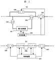
図2は常時「閉」の状態で配電線の相互連系点に設置される連系装置の構成例である。これらは、2組の配電線間を互いに接続してループ構成とするための装置で、ループ内の有効電力(潮流)と無効電力を制御することができる。各配電線の負荷のアンバランスによる変電所送出し電流のアンバランスを解消したり、無効電力制御により電圧を適正範囲に保つ役割がある。
【0027】
同図(a)は、電力変換器を用いた位相調整器と開閉器を組み合わせた構成である。501は電力変換器で、502は配電線と並列に接続され電力変換器501に電力を供給する調整変圧器、503は電力変換器501の出力電圧を配電線に印加するための直列変圧器、504は電力変換器501の制御装置である。506は電力変換器501、制御装置504、調整変圧器502、直列変圧器503に異常、故障が発生したときにこれらをバイパスするための開閉器である。505は配電線の連系点の接続を切り離すための開閉器である。
【0028】
この連系装置は、連系点を通過する有効電力と無効電力を制御できるため、電圧制御、潮流配分の制御に有効である。本装置構成では、装置容量は調整する有効電力及び無効電力に依存するため、比較的小容量で実現可能であり、コスト、通電損失を低く抑えることが可能となる。
【0029】
同図(b)は、直流連系の概念を適用した例で、508は電力変換器、507はその制御装置、509は配電線の連系点の接続を切り離すための開閉器である。
【0030】
この連系装置は、装置容量が設置された配電線の連系点の通過電力で決まるため一般に容量は大きくなる。したがって、コスト、通電損失は高くなるが、一旦直流に変換してから連系するので、一方の配電線側で発生した事故が他方の配電線へ波及するのを防止する効果や短絡電流を抑制する効果が期待できる。
【0031】
本発明では、連系装置の構成を図2(a)、(b)のいずれかに限定するものではない。また、常時「開」の場合には通常の区分開閉器を連系装置として用いることができる。
【0032】
図4は本発明による電力品質維持支援方法の一実施例の手順を示す。品質管理代行会社は電力会社との間に品質管理代行契約を締結する。電力会社は、品質管理代行会社に品質管理代行料金を支払うとともに系統状態データを提供する。品質管理代行会社は系統状態データを基に、電力品質の監視を行う。
【0033】
一方、品質管理代行会社は分散型電源を保有する各需要家と電源運用契約を締結する。需要家がオプションとして電力供給者選択を選んでいる場合には、品質管理代行会社は需要家に対して電力供給者を提示し、需要家は提示された電力会社と契約し電気供給約款に基づき電力を購入し、電力料金を支払う。品質管理代行会社は需要家から提供された電源状態データを基に電源設備の運転を代行し、需要家から運転代行料金を得る。
【0034】
系統の電力品質が低下した場合、品質管理代行会社は品質維持のため系統制御機器に制御指令を送出するとともに、需要家にも電源出力の調整指令を送出する。品質管理代行会社は需要家に品質管理協力費として、電源の出力調整により減少したコストメリット減少分、あるいは協力回数や協力量(無効電力積算値)に関連した対価を支払う。
【0035】
図5は電力品質維持支援方法の具体的な手順として、分散型電源を保有しない需要家の例を示す。品質管理代行会社と電力会社との関係は図4の例と全く同様である。一方、品質管理代行会社は分散型電源を保有しない各需要家とは受電設備監視契約を締結する。需要家がオプションとして電力供給者選択を選んでいる場合には、品質管理代行会社は需要家に対して電力供給者を提示し、需要家は提示された電力会社と契約し電気供給約款に基づき電力を購入し、電力料金を支払う。品質管理代行会社は需要家の受電設備を監視し、異常があれば需要家にその旨を伝送し、需要家から監視料金を得る。
【0036】
系統の電力品質が低下した場合、品質管理代行会社は品質維持のため系統制御機器に制御指令を送出するとともに、需要家に受電設備調整指令(例えば力率改善装置の設定変更等)を送出する。品質管理代行会社は需要家に品質維持協力のために行った設備調整に対して品質管理協力費を支払う。
【0037】
図6は特定地域において電力供給と系統管理を行う配電会社が、電力品質維持支援方法を適用する時の手順を示す。この例は、図4、5に示した品質管理代行会社と電力会社の機能が、配電会社によって実現した場合の例である。図4、5との違いは事業形態だけであり、各需要家との関係は図4及び5の例と同様である。また、制御・運用上も図4、5のように品質代行会社と電力会社が分かれている場合と変わらない。
【0038】
図7は品質管理代行会社と需要家が締結する契約種別の一例を示す。この例では、代行サービスの内容を電源運用代行、設備異常監視、品質管理協力、電力供給者選択代行とし、これらの組み合せにより契約にオプションを設定した。オプション1からオプション3は分散型電源を保有する需要家向けの契約種別であり、オプション4及び5は分散型電源を保有しない需要家向けの契約種別である。
【0039】
次に、本発明の電力品質維持支援システムにおける品質管理センタ1での処理手順を説明する。図8は品質管理センタでの処理フローを示す。以下の処理は所定の時間間隔、例えば5分〜10分程度の間隔で行う。
【0040】
まず、配電系統の状態データとして配電線の所定位置における電圧、電流のデータをモニタリングする(S1)。これは系統に設置されているセンサ付開閉器2A11等や柱上変圧器14等における計測データを、配電変電所制御システム3を介して収集する。モニタリングされた系統状態データは系統状態DB1031に格納される。
【0041】
次に、需要家に設置している通信制御装置7を介して、分散型電源の出力、消費電力量データ等を収集する(S2)。収集された需要家状態は需要家状態DB1033に格納される。
【0042】
S1で収集した系統状態データをもとに、配電線の各フィーダにおいて電圧が逸脱している箇所を探索する(S3)。電圧逸脱点は、一定時間間隔ごとに入手する系統情報、各需要家の受電端電圧から各配電線の電圧プロフィールを作成し、これを適正電圧範囲と比較することで該当する配電線及びその位置(区間)を特定することができる。
【0043】
次に、各配電線で供給している電力量を計算し、各配電線の潮流の配分を算出する(S4)。
【0044】
S3、S4の演算結果を用いて各配電線電圧、潮流に関する評価を行う(S5)。すなわち、各配電線において、電圧逸脱点の有無、潮流配分のばらつきは許容範囲内か(配電損失は許容範囲内か、過負荷の有無)について評価する。
【0045】
評価の結果、全て問題なければS11〜S14の処理を行う。問題があればS6〜S10の処理を行う。ここで、S11〜S14の処理は分散型電源の経済性運用に関する演算処理に相当し、先願(特願2002−159565号)の図6及び図7に示した方法と同様である。
【0046】
S5の評価結果に問題がある場合、電力品質維持制御の対象とする系統制御機器及び需要家を選択し、系統制御機器及び需要家の設備(分散型電源、あるいは力率調整装置)の制御量の初期値を設定する(S6)。
【0047】
例えば、配電線2A1の末端付近で電圧逸脱区間が検出された場合に、対象機器は次のように選択する。図1に示した連系装置51〜53が常時「開」の状態で運用されているループなしの場合を説明する。該当する配電線が接続されている配電変電所のバンク変圧器2Aと、電圧逸脱箇所を含む区間より上流側(区間内も含む)で最も近くにある線路用電圧調整器2A12が選択される。さらに、該当する区間内及び付近の需要家として需要家A及びCが選択される。
【0048】
制御対象となった機器の制御量は、発生している問題に応じて設定される。例えば、電圧上限値の逸脱が発生していれば、バンク変圧器2A及び線路用電圧調整器2A12には1タップ下げ、需要家A及びCには分散型電源の無効電力変更量(系統側からみて、遅れで力率0.01相当)を設定する。
【0049】
次に、図1に示した連系装置51〜53が常時「閉」の状態で運用されているループありの場合を説明する。例えば、該当する配電線が接続されている配電変電所のバンク変圧器2Aと、該当する配電線2A1の電圧逸脱箇所を含む区間の近くに設置されている連系装置52が選択される。さらに、該当する区間内及び付近の需要家として需要家A及びCが選択される。場合によっては、需要家Bも制御対象の候補となる。この場合もループなしの場合と同様に、制御対象となった機器の制御量は発生している問題に応じて設定される。
【0050】
確認のためモニタリングした系統状態データ及び需要家状態データに加えて、S6で設定した各装置の制御初期値を用いて系統シミュレーション(潮流計算)を行い、各配電線の電圧分布、潮流分布を計算する(S7)。
【0051】
シミュレーション結果として得られた各配電線の電圧、潮流に関して、S5と同様な評価を行う(S8)。すなわち、各配電線において、電圧逸脱点の有無、潮流配分のばらつきは許容範囲内か(配電損失は許容範囲内か、過負荷の有無)について評価する。全て問題なければS9へ進み、問題が解消されなければS6へ戻り各機器の制御量を変更して再びS6〜S8の処理を行う。
【0052】
S8で問題なければ、制御対象となる系統制御機器、需要家の分散型電源に対して、シミュレーションで決定された制御指令値を、通信制御装置101を介して伝送する(S9)。
【0053】
同時に品質維持制御の対象となった需要家の貢献度を評価し(S10)、需要家貢献度DB1034のデータに登録、更新した後、次の時間ステップの処理に移る。
【0054】
品質管理協力費は、例えば、無効電力制御による貢献度に対しては、品質維持への協力回数に応じてx¥/回数のような形で対価を支払う。あるいは品質維持のために調整した無効電力量を積算して記録しておき、1ヶ月単位でy¥/kVarのような形で対価を支払う。また、分散型電源の有効電力制限による貢献度に対しては、例えば、品質維持のために制限した有効電力の電力量(kWh)を記録しておき、コストメリット減少分(=制限された有効電力量(kWh)×売電単価(¥/kWh))を対価として支払うようにする。
【0055】
S5の評価の結果、問題なければ各需要家の分散型電源9の出力制御指令値を計算する(S11)。発電特性データベース1035や外部データベース1036から取得した天候、気温等の予測データを用いて、設備運用コストが最小となるように発電出力量を最適化する。
【0056】
S1、S2でモニタリングした系統状態データ及び需要家状態データと、S11で変更した電源の出力制御指令値を用いて系統シミュレーション(潮流計算)を行い、各配電線の電圧、潮流分布を計算する(S12)。
【0057】
シミュレーション結果として得られた各配電線の電圧、潮流に関して、S5と同様な評価を行う(S13)。各配電線において、電圧逸脱点の有無、潮流配分のばらつきは許容範囲内か(配電損失は許容範囲内か、過負荷の有無)について評価する。問題があればS11へ戻り、各分散型電源の出力制御指令値を変更して再び系統シミュレーションを行う。
【0058】
全て問題なければS14へ進み、各需要家の分散型電源に対して、シミュレーションで決定された出力制御指令値を、通信制御装置101を介して伝送する。
【0059】
次に、本実施例による電力品質維持に関する制御動作の効果を説明する。図9は電圧上限値の逸脱が発生した時の制御動作例である。図1に示した連系装置51〜53が常時「開」の状態で運用されているループなしの場合に、配電線2A1で電圧上限値の逸脱が発生した例である。(a)は配電変電所の送り出し電圧制御、(b)は線路用電圧調整器による電圧制御、(c)は分散型電源の無効電力制御による電圧調整の例である。
【0060】
配電線2A1において、需要家A及びCnの保有する分散型電源が逆潮流すると、図9(a)の破線のように電圧が上昇して適性範囲を逸脱する。この時、該当する配電線が接続されている配電変電所のバンク変圧器2Aが選択され、送り出し電圧を下げるようにタップを切り換え、(a)の実線のような電圧分布を得る。
【0061】
次に、電圧逸脱箇所を含む区間より上流側(区間内も含む)で最も近くにある線路用電圧調整器2A12が選択され、電圧を下げるようにタップを切り換えて(b)の実線のような電圧分布を得る。さらに、適正範囲に入らない区間については、需要家A及Cnが保有する分散型電源から無効電力(系統から見て遅れ)を供給し、さらに電圧を低下させて、適正範囲内に抑えることができる。
【0062】
図10は、図1に示した連系装置51〜53が常時「閉」の状態で運用されているループありの場合に、配電線2A1で電圧上限値の逸脱、配電線2A2で重負荷による電圧下限値の逸脱が発生した時の制御動作例である。(a)は配電変電所の送り出し電圧制御、(b)は連系装置の有効・無効電力制御による電圧制御、(c)は分散型電源の無効電力制御による電圧調整である。
【0063】
配電線2A1において、需要家A及びCnの保有する分散型電源が逆潮流し、(a)の破線のように電圧が上昇し、かつ需要家Bの負荷により著しく電圧降下が発生し、それぞれ適性範囲を逸脱したと想定する。この時、該当する配電線が接続されている配電変電所のバンク変圧器2Aが選択され、送り出し電圧を下げるようにタップを切り換え、(a)の実線のような電圧分布を得る。
【0064】
次に、該当する配電線2A1、2A2に設置されている連系装置52が選択され、有効電力制御により潮流配分を調整し、無効電力制御により電圧を適正範囲に近づける。この時点で配電線2A2は適正範囲に収まった。さらに、それでも適正範囲に入らない配電線2A1の区間について、需要家A及びCnが保有する分散型電源から無効電力(系統から見て遅れ)を供給し、当該区間の電圧を低下させて適正範囲内に抑えることができる。
【0065】
このように、系統制御機器と需要家の分散型電源の設備を協調して制御することで、分散型電源が配電系統に大量に導入された場合でも、配電線増設などの設備投資を必要とせずに配電系統の電力品質を適正な状態に維持することができる。また、本発明では分散型電源のユーザでもある需要家自身が品質維持に協力するため、分散型電源の系統連系条件を厳しくして需要家への電圧補償装置設置の義務付け、小規模電源への逆潮流制限や接続制限などを課す必要がなくなる。それゆえ、分散型電源の導入障壁を低くできるとともに、分散型電源の運用の制約も小さくできるため、分散型電源導入による需要家のコストメリットを確保できる。
【0066】
図11に品質管理センタの管理サーバで使用するデータファイルの構成例を示す。品質管理センタ1の記憶装置103内には、モニタリングした各配電線の所定位置の電圧、電流等の系統状態データを格納したデータ1031のファイルがある。また、各フィーダに設置してあるセンサ付開閉器2A11、線路用電圧補償装置2A12、柱上変圧器14、配電線の連系装置51〜53等、系統制御機器の状態(稼動状態、制御値等)を格納した系統制御機器データ1032のファイルがある。また、モニタリングした各需要家の電源出力、負荷等のデータを格納した需要家状態データ1033、各需要家の品質管理に対する協力を示す需要家貢献度データ1034、各分散型電源の発電特性データ1035のファイルがある。さらに、外部のデータベースより通信回線を介して逐次取得して整理、格納した天候予測データ、風況予測データ、気温予測データのファイルとで構成される。
【0067】
図12に電力品質維持支援システムの管理サーバの出力画面の一例を示す。配電系統状態表示として、配電線毎にモニタリングした各部の電圧、電流値、電圧逸脱発生の有無、負荷率、系統故障の有無等を表示する。また、需要家状態表示として、需要家毎に受電契約内容、保有する電源種別、モニタリングした発電出力を表示する。さらに、全て購入電力でまかなった場合のコスト(電力料金)に対するコストメリット(%)、電力品質維持制御への協力回数(回)、需要家の設備異常の有無等を表示する。
【0068】
【発明の効果】
本発明によれば、系統制御機器と需要家設備(分散型電源あるいは力率調整装置)を協調して制御することで、配電系統の電力品質を適正な状態に維持することができる。
【0069】
電力会社としては、需要家の保有する分散型電源や力率調整装置などに電力品質維持の一翼を担ってもらうことで、分散型電源が多数連系した場合でも配電線増設などの電力品質維持に係る設備投資を抑制することができる。
【0070】
また、必要以上に分散型電源の系統連系条件を厳しくする必要がなくなるので、需要家にとって分散型電源の導入障壁が低くなるとともに、電源運用の制約も小さくできるので分散型電源導入によるコストメリットの減少を防止できる。したがって、分散型電源の普及の阻害要因を排除することができる。
【図面の簡単な説明】
【図1】本発明の一実施例である電力品質維持支援システムの構成を示す単線結線図。
【図2】配電線の相互連系点に設置される連系装置のブロック構成図。
【図3】本発明の電力品質維持支援方法によるビジネスの基本形態となる概念図。
【図4】本発明の電力品質維持支援方法によるビジネスの一例を示す流れ図。
【図5】本発明の電力品質維持支援方法によるビジネスの他の例を示す流れ図。
【図6】本発明の電力品質維持支援方法によるビジネスの更に他の例を示す流れ図。
【図7】品質管理代行会社と需要家の間の契約種別の例を示す説明図。
【図8】本発明の一実施例による電力品質維持支援方法の手順を示すフローチャート。
【図9】電力品質維持支援システムの制御動作の効果を示す電圧遷移図。
【図10】電力品質維持支援システムの他の制御動作の効果を示す電圧遷移図。
【図11】管理サーバで使用するデータファイルの構成図。
【図12】管理サーバの表示画面の一例を示す画面構成図。
【符号の説明】
1…品質管理センタ、101…通信制御装置、102…管理サーバ、103…記憶装置、2…配電変電所、2A,2B…バンク変圧器、2A1,2A2,2B1,2B2…配電線、2A3,2A4,2A5…配電線連系線、2A11…センサ付開閉器、2A12…線路用電圧調整器、3…配電変電所制御システム、41,42…通信回線、51〜53…連系装置、7…通信制御端末、8…負荷、9…分散型電源、10…力率調整装置、11,13…遮断器、12…受電用変圧器、14…柱上変圧器。[0001]
TECHNICAL FIELD OF THE INVENTION
The present invention relates to a distribution system and a distributed power supply control / operation method for maintaining power supply reliability and power quality in a distribution system in which a plurality of distributed power sources are interconnected.
[0002]
[Prior art]
In the domestic electric power business, deregulation of the “expansion of retail liberalization” is being considered. In March 2000, retail liberalization for large-scale customers was expanded. In 2005, application to high-voltage customers was expanded. Is scheduled to be fully liberalized for low-voltage consumers such as ordinary households. Along with this, it is expected that new retailers such as PPS (Power Producer and Supplier) will increase. On the other hand, from the viewpoint of effective use of natural energy, it is considered that the installed capacity of the distributed power supply is significantly increased.
[0003]
When these become reality, a large number of distributed power sources will be connected to the distribution system.For example, reverse power flow to the distribution system and an increase in short-circuit current will become apparent, and power quality and supply reliability will decrease. There is concern. In particular, maintaining an appropriate voltage is an important issue.
[0004]
Conventionally, there are few distributed power supplies connected to a distribution line, and the voltage tends to decrease toward the end of the distribution line. Therefore, as described in Electric Cooperative Research Vol. 56, No. 4, the delivery voltage of the distribution substation (transformer secondary bus voltage) is adjusted according to the magnitude of the load current of the distribution line. , Compensate for voltage drop. In particular, when the influence of the voltage drop is large, the voltage drop is compensated by using a line voltage regulator installed in the middle of the distribution line. Further, measures such as changing the system configuration by switching the section switches to eliminate the tidal current neck may be taken. As described above, basically all measures are taken on the distribution system side.
[0005]
In a system in which a large number of distributed power supplies are connected, a voltage rise due to reverse power flow of the power supply becomes a problem. At present, according to the grid interconnection guidelines, it is obligatory for the distributed power supply connected to the grid to have a function (power factor adjustment, output limitation) for suppressing a voltage rise in the power supply control device. In this case, depending on the installation position and the conditions of the distribution lines connected to the system, the output of only the power source owned by a specific customer may be limited at all times, and unfairness such as the merit of installing the power source cannot be obtained. There is a possibility.
[0006]
Therefore, an electric power supplier installs distributed power sources such as solar cells, fuel cells, and micro gas turbines in users such as ordinary homes, apartment houses, and small business establishments. There is a description in
[0007]
[Patent Document 1]
JP-A-2002-152976 (paragraphs 0032-0041, FIG. 1)
[0008]
[Problems to be solved by the invention]
When a large number of distributed power sources are interconnected and output a reverse power flow to the distribution system, the distribution of voltage on the distribution line changes from a monotonous drop to a very complicated distribution, such as an increase in voltage on the way. Therefore, it may not be possible to cope with the above-described complicated voltage distribution compensation only by the combination of the delivery voltage control and the line voltage regulator in the conventional distribution substation.
[0009]
In addition, in the method of improving the voltage distribution by eliminating the power flow neck of the distribution line using the section switch, it is considered that it is necessary to frequently change the system configuration. Inability to withstand frequent operations. To solve these problems, there is a method to increase the number of distribution lines, but it is not a practical measure because the economic burden on the grid operator is large.
[0010]
It is also conceivable that the electric power company, as a system administrator, may tighten the system interconnection conditions for distributed power sources, oblige consumers to install voltage compensators, and impose restrictions on reverse power flow and connection to small-scale power sources. . However, these are factors that hinder the spread of distributed power generation, and are not completely acceptable given the social trend of effective energy use for environmental protection.
[0011]
On the other hand, in
[0012]
An object of the present invention is to provide a power quality maintenance support method and system by flexible interconnection of a power distribution system and a distributed power supply in view of the above-described problems of the related art.
[0013]
[Means for Solving the Problems]
In order to solve the above-mentioned problems, in the present invention, a quality control center is installed, a power supply operation data of a customer and a system state of a distribution system are obtained online, and a power quality maintenance device installed in a distributed power supply and a distribution system. Are coordinated to calculate the respective control values, so that the output command of the distributed power supply is transmitted to the customer and the control command of the quality maintenance device is transmitted to the system administrator.
[0014]
The present inventors have applied for Japanese Patent Application No. 2002-159565 in connection with the above problem. The outline of this earlier application is as follows. Based on contracts between the power information service provider and the contractor A (a company that owns the regional transmission and distribution system) and the contractor B (a customer with a distributed power source), the power information at the distribution substation and each customer Own collection means and collect information. Based on the collected information, the supply capacity and the power shortage are compared between the generators in the system, and the output of the distributed power source is set, and the center applies for an increase in the output of the distributed power source. When an application is made, information on the operation status of the local grid, such as voltage and section current, is collected, and based on these information, a simulation of the power flow and voltage distribution in the local transmission and distribution system is performed. It determines whether it is possible, and if possible, gives an instruction to the voltage regulator and an instruction to the distributed power supply.
[0015]
In other words, the prior application is an invention in which, if a power quality problem occurs during power transfer, the problem can be resolved as much as possible to enable the transfer. Specifically, when there is a problem with the voltage and power flow at the time of application for consignment, it waits for a certain period of time, and if it is still not improved, the consignment, that is, the output change of the distributed power supply is forgotten, and means for improving power quality are installed in the system There is only a voltage regulator.
[0016]
On the other hand, the present invention is an extension of the above-mentioned prior application invention. The purpose of the present invention is to maintain power quality not only at the time of changing the output of a power supply by consignment, but also at the time of a system (load) state that is constantly changing in an operating state. In order to realize this, not only the equipment on the grid side but also the cooperation of the customers (reactive power control of the distributed power supply and control of the power factor adjustment device) are requested, and the output restriction is not imposed on the distributed power supply as much as possible. Is to do so. Therefore, it is possible to cope with a large-scale connection or a centralized connection of an unstable distributed power supply (for example, a power supply using natural energy such as solar power generation) which causes a large load fluctuation at all times.
[0017]
Although the prior invention does not show a method for controlling the voltage regulator installed in the system as a specific measure against the voltage problem, the present invention presents the control method in detail.
[0018]
Further, in the prior application, the customer to be contracted, that is, controlled, is only the user (contractor B) holding the distributed power supply. However, in the present invention, in order to have the customer cooperate thinly and widely in order to maintain the power quality and to increase the degree of freedom of control, consumers who do not have a distributed power supply but have a power factor adjusting device are also controlled. . In addition, it has a concept that is not seen in previous applications, in which consumers are encouraged to contribute to the improvement of voltage problems and the like and pay for it.
[0019]
BEST MODE FOR CARRYING OUT THE INVENTION
Prior to the description of the embodiments of the present invention, a basic framework of a power quality maintenance support system for a distribution system to which the present invention is applied will be described.
[0020]
FIG. 3 is a business conceptual diagram showing a basic framework of the present invention. Establish a quality management and supply and demand coordination agency, which concludes equipment monitoring and operation contracts with the customer group, provides customers with distributed power supply operation and equipment abnormality monitoring services, and provides contract fees and control. Get the information you need. Here, the contract includes cooperation for maintaining power quality. On the other hand, a quality management agency contract is concluded with the electric power company, the system status necessary for control calculation is obtained under a predetermined contract fee, and the power quality of the system is monitored. When a problem occurs in maintaining the power quality, a control command to the system control device and the distributed power source is sent to a power company or a customer to try to solve the problem.
[0021]
Next, an embodiment of the present invention will be described. FIG. 1 is a single-line diagram showing the configuration of the power quality maintenance support system of the present invention. The present invention mainly relates to a
[0022]
In this example, the
[0023]
Each customer is connected to a distribution line via a
[0024]
The customer A is a relatively large-scale customer who receives power under high-voltage interconnection conditions and has a distributed power source, and the customer B is a customer who receives power under high-voltage interconnection conditions and does not have a distributed power source, and customers C1 to Cn. Is assumed to be a customer who receives power under low-voltage interconnection conditions and owns a small distributed power source. Examples of the customer A include customers having an important load, such as a process factory, an intelligent building, and a hospital. Examples of the customer B include a production factory and an office building having no significant load. As an example of the customer C, a general household, a small office, a combination, or the like has a distributed power supply such as a photovoltaic power generator, a fuel cell, and a micro gas turbine.
[0025]
The
[0026]
FIG. 2 is a configuration example of an interconnecting device installed at an interconnecting point of a distribution line in a normally “closed” state. These are devices for connecting two sets of distribution lines to each other to form a loop, and can control active power (power flow) and reactive power in the loop. It has the role of eliminating the imbalance of the substation sending current due to the imbalance of the load on each distribution line, and maintaining the voltage in an appropriate range by reactive power control.
[0027]
FIG. 1A shows a configuration in which a phase adjuster using a power converter and a switch are combined. 501 is a power converter, 502 is an adjusting transformer connected in parallel with the distribution line to supply power to the
[0028]
Since this interconnection device can control the active power and the reactive power passing through the interconnection point, it is effective for voltage control and power flow distribution control. In the present device configuration, the device capacity depends on the active power and the reactive power to be adjusted, so that the device capacity can be realized with a relatively small capacity, and the cost and the conduction loss can be reduced.
[0029]
FIG. 2B shows an example in which the concept of DC interconnection is applied, wherein 508 is a power converter, 507 is its control device, and 509 is a switch for disconnecting the interconnection point of the distribution line.
[0030]
This interconnection device generally has a large capacity because the device capacity is determined by the passing power at the interconnection point of the installed distribution line. Therefore, the cost and conduction loss are high, but since they are converted to direct current and then connected, the effect of preventing an accident that occurred on one distribution line from spreading to the other distribution line and suppressing the short-circuit current Can be expected to be effective.
[0031]
In the present invention, the configuration of the interconnection device is not limited to any of FIGS. 2A and 2B. In addition, when it is always “open”, a normal sectional switch can be used as the interconnection device.
[0032]
FIG. 4 shows the procedure of an embodiment of the power quality maintenance support method according to the present invention. The quality management agency enters into a quality management agency contract with the power company. The power company pays the quality management agency fee to the quality management agency company and provides the system status data. The quality control agency monitors the power quality based on the system status data.
[0033]
On the other hand, the quality management agency concludes a power supply operation contract with each customer who has a distributed power supply. If the customer has selected the option of electric power supplier as an option, the quality control agency presents the electric power supplier to the customer, and the customer contracts with the indicated electric power company and based on the electricity supply agreement. Buy power and pay for electricity. The quality management agency company operates the power supply equipment on the basis of the power supply state data provided by the customer, and obtains an operation agency fee from the customer.
[0034]
When the power quality of the power system is degraded, the quality management agency sends a control command to the grid control device to maintain the quality, and also sends a power output adjustment command to the customer. The quality management agency company pays the customer a quality management cooperation fee for the reduced cost merit due to the adjustment of the output of the power supply, or for the number of cooperation and the amount of cooperation (reactive power integrated value).
[0035]
FIG. 5 shows an example of a customer who does not have a distributed power source as a specific procedure of the power quality maintenance support method. The relationship between the quality management agency and the power company is exactly the same as in the example of FIG. On the other hand, the quality management agency enters into a power receiving equipment monitoring contract with each customer who does not have a distributed power source. If the customer has selected the option of electric power supplier as an option, the quality control agency presents the electric power supplier to the customer, and the customer contracts with the indicated electric power company and based on the electricity supply agreement. Buy power and pay for electricity. The quality control agency monitors the power receiving equipment of the customer, and if there is any abnormality, transmits the fact to the customer and obtains a monitoring fee from the customer.
[0036]
When the power quality of the power system deteriorates, the quality management agency sends a control command to the grid control device to maintain the quality, and also sends a power receiving equipment adjustment command (for example, a change in the setting of the power factor improvement device) to the customer. . The quality control agency pays the quality control cooperation fee to the customer for the equipment adjustment performed for the quality maintenance cooperation.
[0037]
FIG. 6 shows a procedure when a power distribution company that performs power supply and grid management in a specific area applies the power quality maintenance support method. This example is an example in which the functions of the quality management agent company and the electric power company shown in FIGS. 4 and 5 is only the business form, and the relationship with each customer is the same as in the examples of FIGS. Also, the control and operation are the same as in the case where the quality agency and the power company are separated as shown in FIGS.
[0038]
FIG. 7 shows an example of the type of contract concluded between the quality management agency and the customer. In this example, the contents of the agency service are a power supply operation agency, equipment abnormality monitoring, quality management cooperation, and a power supplier selection agency, and options are set in the contract by a combination of these.
[0039]
Next, a processing procedure in the
[0040]
First, data of voltage and current at a predetermined position of a distribution line is monitored as state data of the distribution system (S1). This collects the measurement data of the switch with sensor 2A11 and the
[0041]
Next, the output of the distributed power supply, power consumption data, and the like are collected via the
[0042]
Based on the system status data collected in S1, a location where the voltage deviates in each feeder of the distribution line is searched (S3). The voltage deviation point is determined by creating a voltage profile of each distribution line from the system information obtained at regular time intervals and the receiving end voltage of each customer, and comparing this with the appropriate voltage range to find the corresponding distribution line and its location. (Section) can be specified.
[0043]
Next, the amount of electric power supplied by each distribution line is calculated, and the distribution of the power flow of each distribution line is calculated (S4).
[0044]
The distribution line voltage and power flow are evaluated using the calculation results of S3 and S4 (S5). That is, in each distribution line, the evaluation is made as to whether or not there is a voltage deviation point and whether the distribution of power flow is within an allowable range (distribution loss is within an allowable range, or whether or not there is an overload).
[0045]
As a result of the evaluation, if there is no problem, the processes of S11 to S14 are performed. If there is a problem, the processing of S6 to S10 is performed. Here, the processing of S11 to S14 corresponds to the arithmetic processing regarding the economical operation of the distributed power supply, and is the same as the method shown in FIGS. 6 and 7 of the prior application (Japanese Patent Application No. 2002-159565).
[0046]
If there is a problem in the evaluation result of S5, the system control device and the customer to be subjected to the power quality maintenance control are selected, and the control amount of the system control device and the customer's equipment (distributed power supply or power factor adjusting device) is selected. Is set (S6).
[0047]
For example, when a voltage deviation section is detected near the end of the distribution line 2A1, the target device is selected as follows. A case where there is no loop in which the interconnecting
[0048]
The control amount of the device to be controlled is set according to the problem that has occurred. For example, if a deviation from the voltage upper limit occurs, the tap is lowered by one tap to the bank transformer 2A and the line voltage regulator 2A12, and the reactive power change amount of the distributed power supply (from the grid side) to the consumers A and C. Therefore, a power factor of 0.01 is set with a delay).
[0049]
Next, a case where there is a loop in which the interconnecting
[0050]
In addition to the system status data and customer status data monitored for confirmation, a system simulation (power flow calculation) is performed using the control initial values of each device set in S6, and the voltage distribution and power flow distribution of each distribution line are calculated. (S7).
[0051]
With respect to the voltage and power flow of each distribution line obtained as a simulation result, the same evaluation as in S5 is performed (S8). That is, in each distribution line, the evaluation is made as to whether or not there is a voltage deviation point and whether the distribution of power flow is within an allowable range (distribution loss is within an allowable range, or whether or not there is an overload). If there is no problem, the process proceeds to S9, and if the problem is not solved, the process returns to S6 to change the control amount of each device and perform the processes of S6 to S8 again.
[0052]
If there is no problem in S8, the control command value determined by the simulation is transmitted to the system control device to be controlled and the distributed power supply of the consumer via the communication control device 101 (S9).
[0053]
At the same time, the degree of contribution of the customer who has been subjected to the quality maintenance control is evaluated (S10), and the data is registered and updated in the data of the
[0054]
For the quality management cooperation fee, for example, a contribution is paid for the degree of contribution by the reactive power control in a form such as x ¥ / number of times in accordance with the number of times of cooperation for quality maintenance. Alternatively, the amount of reactive power adjusted for quality maintenance is integrated and recorded, and a fee is paid in units of y / kVar in units of one month. In addition, for the contribution by the active power limitation of the distributed power source, for example, the power amount (kWh) of the active power limited for maintaining the quality is recorded, and the cost merit reduction (= limited effective power) is recorded. The amount of power (kWh) × the unit price of power sale ($ / kWh) is paid as a consideration.
[0055]
As a result of the evaluation in S5, if there is no problem, the output control command value of the distributed
[0056]
A system simulation (power flow calculation) is performed using the system status data and the customer status data monitored in S1 and S2 and the output control command value of the power supply changed in S11, and the voltage and power flow distribution of each distribution line are calculated ( S12).
[0057]
With respect to the voltage and power flow of each distribution line obtained as a simulation result, the same evaluation as in S5 is performed (S13). For each distribution line, evaluate whether there is a voltage deviation point and whether the distribution of power flow is within the allowable range (distribution loss is within the allowable range, or whether there is an overload). If there is a problem, return to S11, change the output control command value of each distributed power supply, and perform the system simulation again.
[0058]
If there is no problem, the process proceeds to S14, and the output control command value determined by the simulation is transmitted to the distributed power supply of each customer via the
[0059]
Next, the effect of the control operation for maintaining the power quality according to the present embodiment will be described. FIG. 9 shows a control operation example when a deviation from the voltage upper limit occurs. This is an example in which the deviation of the voltage upper limit value occurs in the distribution line 2A1 when there is no loop in which the interconnecting
[0060]
In the distribution line 2A1, when the distributed power sources owned by the customers A and Cn flow backward, the voltage rises as shown by the broken line in FIG. 9A and deviates from the appropriate range. At this time, the bank transformer 2A of the distribution substation to which the corresponding distribution line is connected is selected, and taps are switched so as to lower the sending voltage, thereby obtaining a voltage distribution as shown by the solid line in (a).
[0061]
Next, the line voltage regulator 2A12 which is closest to the upstream side (including the section) of the section including the voltage deviation point is selected, and the tap is switched so as to lower the voltage, and the tap is switched as shown by the solid line in (b). Obtain the voltage distribution. Furthermore, for sections that do not fall within the proper range, the reactive power (delayed from the viewpoint of the system) is supplied from the distributed power sources owned by the customers A and Cn, and the voltage is further reduced to keep the voltage within the proper range. it can.
[0062]
FIG. 10 shows the case where there is a loop in which the interconnecting
[0063]
In the distribution line 2A1, the decentralized power sources owned by the customers A and Cn flow backward, the voltage rises as indicated by the broken line in (a), and the voltage of the customer B causes a significant voltage drop. Assume out of range. At this time, the bank transformer 2A of the distribution substation to which the corresponding distribution line is connected is selected, and taps are switched so as to lower the sending voltage, thereby obtaining a voltage distribution as shown by the solid line in (a).
[0064]
Next, the
[0065]
In this way, by coordinating control of the system control equipment and the customer's distributed power supply equipment, even if a large amount of distributed power supply is introduced into the distribution system, capital investment such as additional distribution lines is required. The power quality of the power distribution system can be maintained in an appropriate state without using the power supply. In addition, in the present invention, since the customers themselves who are also users of the distributed power supply cooperate in maintaining the quality, the system interconnection conditions of the distributed power supply are strictly required, and the installation of the voltage compensating device in the customer is obliged, and the small power supply is required. There is no need to impose reverse power flow restrictions or connection restrictions. Therefore, the barrier for introducing the distributed power source can be reduced, and the restriction on the operation of the distributed power source can be reduced, so that the cost merit of the customer due to the introduction of the distributed power source can be secured.
[0066]
FIG. 11 shows a configuration example of a data file used by the management server of the quality management center. In the
[0067]
FIG. 12 shows an example of an output screen of the management server of the power quality maintenance support system. As the distribution system status display, the voltage, current value, presence / absence of voltage deviation, load factor, presence / absence of system failure, and the like of each unit monitored for each distribution line are displayed. In addition, as the customer status display, the content of the power reception contract, the type of power source held, and the monitored power generation output are displayed for each customer. Further, the cost merit (%) relative to the cost (power rate) when all the power is covered by the purchased power, the number of times of cooperation for power quality maintenance control (times), the presence / absence of a customer facility abnormality, and the like are displayed.
[0068]
【The invention's effect】
ADVANTAGE OF THE INVENTION According to this invention, the power quality of a distribution system can be maintained in an appropriate state by controlling a grid control apparatus and a customer facility (distributed power supply or a power factor adjustment apparatus) cooperatively.
[0069]
As a power company, the distributed power sources and power factor adjustment devices owned by customers can play a part in maintaining power quality, so even if many distributed power sources are interconnected, maintain power quality such as adding distribution lines. Can reduce capital investment.
[0070]
In addition, there is no need to tighten the grid connection conditions of the distributed power supply more than necessary, which reduces the barriers for consumers to introduce the distributed power supply and reduces the restrictions on the operation of the power supply. Can be prevented from decreasing. Therefore, it is possible to eliminate a factor inhibiting the spread of the distributed power supply.
[Brief description of the drawings]
FIG. 1 is a single-line diagram showing a configuration of a power quality maintenance support system according to an embodiment of the present invention.
FIG. 2 is a block diagram of an interconnection device installed at an interconnection point of a distribution line.
FIG. 3 is a conceptual diagram showing a basic form of business according to the power quality maintenance support method of the present invention.
FIG. 4 is a flowchart showing an example of a business according to the power quality maintenance support method of the present invention.
FIG. 5 is a flowchart showing another example of business according to the power quality maintenance support method of the present invention.
FIG. 6 is a flowchart showing still another example of business by the power quality maintenance support method of the present invention.
FIG. 7 is an explanatory diagram showing an example of a contract type between a quality management agent company and a customer.
FIG. 8 is a flowchart illustrating a procedure of a power quality maintenance support method according to an embodiment of the present invention.
FIG. 9 is a voltage transition diagram showing the effect of the control operation of the power quality maintenance support system.
FIG. 10 is a voltage transition diagram showing the effect of another control operation of the power quality maintenance support system.
FIG. 11 is a configuration diagram of a data file used in the management server.
FIG. 12 is a screen configuration diagram illustrating an example of a display screen of the management server.
[Explanation of symbols]
DESCRIPTION OF
Claims (8)
入手した系統状態データから配電線に電圧および/または潮流が適正範囲を逸脱する異常がある場合に、前記異常の解消に寄与できる系統制御機器及び需要家を選択し、前記配電線の異常を解消するように前記制御値を決定することを特徴とする配電系統の電力品質維持支援方法。In claim 1 or 2,
If there is an abnormality in the distribution line where the voltage and / or power flow deviates from the appropriate range from the obtained system state data, a system control device and a customer that can contribute to the elimination of the abnormality are selected, and the abnormality of the distribution line is eliminated. A power quality maintenance support method for a power distribution system, wherein
前記配電線の異常を解消する前記制御値は、系統側で前記配電線への送り出し電圧や線路用電圧調整器の調整量、需要家側で前記分散電源の無効電力量であることを特徴とする配電系統の電力品質維持支援方法。In claim 3,
The control value for eliminating the abnormality of the distribution line, the output voltage to the distribution line and the adjustment amount of the line voltage regulator on the system side, the reactive power amount of the distributed power supply on the customer side, To maintain the power quality of the distribution system.
代行会社は、電力会社から配電系統の系統状態データ、需要家から分散型電源の運転データをオンラインで入手し、配電系統に電圧および/または潮流が適正範囲を逸脱する異常がある場合に、前記異常に関係する系統制御機器及び需要家の分散型電源を選択し、前記異常を解消するように系統制御機器制御指令を電力会社に、電源出力調整指令を需要家にオンラインで送出することを特徴とする配電系統の電力品質維持支援方法。In a support method for a proxy company to connect a power company and a customer through a network, monitor the power quality of the distribution system, and maintain the quality,
The agency acquires online the system status data of the distribution system from the power company and the operation data of the distributed power supply from the customer, and when the distribution system has an abnormality in which the voltage and / or power flow deviates from the appropriate range, It is characterized in that a system control device related to the abnormality and a distributed power source of the customer are selected, and a system control device control command is sent to the power company and a power output adjustment command is sent to the customer online so as to eliminate the abnormality. Power quality maintenance support method for distribution system.
代行会社は予め需要家と前記分散型電源の電源運用契約を結び、前記分散型電源の遠隔運転や前記異常のときの電源出力調整指令の出力を行なうことを特徴とする配電系統の電力品質維持支援方法。In claim 6,
The agency company concludes a power supply operation contract for the distributed power supply with a customer in advance, and performs remote operation of the distributed power supply and outputs a power output adjustment command in the event of the abnormality, thereby maintaining power quality of the distribution system. How to help.
代行会社は、前記電源出力調整の指令に対する需要家の協力の回数または程度を計測し、品質管理協力費を算出することを特徴とする配電系統の電力品質維持支援方法。In claim 7,
A power quality maintenance support method for a distribution system, wherein the agency company measures the number or degree of customer cooperation with the power supply output adjustment command and calculates a quality management cooperation fee.
Priority Applications (1)
| Application Number | Priority Date | Filing Date | Title |
|---|---|---|---|
| JP2003058448A JP2004274812A (en) | 2003-03-05 | 2003-03-05 | Power quality maintenance support method and system in distribution system |
Applications Claiming Priority (1)
| Application Number | Priority Date | Filing Date | Title |
|---|---|---|---|
| JP2003058448A JP2004274812A (en) | 2003-03-05 | 2003-03-05 | Power quality maintenance support method and system in distribution system |
Publications (1)
| Publication Number | Publication Date |
|---|---|
| JP2004274812A true JP2004274812A (en) | 2004-09-30 |
Family
ID=33121558
Family Applications (1)
| Application Number | Title | Priority Date | Filing Date |
|---|---|---|---|
| JP2003058448A Pending JP2004274812A (en) | 2003-03-05 | 2003-03-05 | Power quality maintenance support method and system in distribution system |
Country Status (1)
| Country | Link |
|---|---|
| JP (1) | JP2004274812A (en) |
Cited By (34)
| Publication number | Priority date | Publication date | Assignee | Title |
|---|---|---|---|---|
| JP2006333618A (en) * | 2005-05-25 | 2006-12-07 | Central Res Inst Of Electric Power Ind | Communication network for distribution network monitoring and control |
| JP2007110809A (en) * | 2005-10-12 | 2007-04-26 | Tokyo Electric Power Co Inc:The | SUPPORT SYSTEM AND METHOD FOR DETERMINING CONDITIONS FOR CONNECTING DISTRIBUTED POWER SUPPLY TO DISTRIBUTION NETWORK |
| JP2007288877A (en) * | 2006-04-14 | 2007-11-01 | Hitachi Ltd | Power quality maintenance support method and power quality maintenance support system for a distribution system in which a plurality of distributed power sources are connected |
| JP2008005672A (en) * | 2006-06-26 | 2008-01-10 | Chugoku Electric Power Co Inc:The | Power generation power factor selecting system of distributed power supply, power generation power factor selecting method of distributed power supply, and program |
| JP2008077369A (en) * | 2006-09-21 | 2008-04-03 | Chugoku Electric Power Co Inc:The | Information providing server, information providing method, and information providing program |
| JP2008187806A (en) * | 2007-01-29 | 2008-08-14 | Chugoku Electric Power Co Inc:The | Distributed power supply transfer interrupting system and its communicating method |
| WO2008139758A1 (en) * | 2007-05-08 | 2008-11-20 | Mitsubishi Electric Corporation | Power quality compensator |
| CN100446376C (en) * | 2005-09-29 | 2008-12-24 | 株式会社日立制作所 | Cogeneration equipment control system and cogeneration equipment control method |
| JP2009065817A (en) * | 2007-09-10 | 2009-03-26 | Kansai Electric Power Co Inc:The | Voltage control method for distribution system |
| JP2010183701A (en) * | 2009-02-04 | 2010-08-19 | Mitsubishi Electric Corp | Voltage monitor control method by voltage monitor control system of distribution system |
| JP2011036091A (en) * | 2009-08-05 | 2011-02-17 | Sanken Electric Co Ltd | Voltage regulator and voltage-adjusting method |
| JP2011130638A (en) * | 2009-12-21 | 2011-06-30 | Hitachi Ltd | Power generation system using natural energy |
| WO2011102374A1 (en) * | 2010-02-17 | 2011-08-25 | トヨタ自動車株式会社 | Power system for residence |
| JP2011210257A (en) * | 2010-03-26 | 2011-10-20 | Palo Alto Research Center Inc | Technique for aggregating energy service from participants at one or more locations |
| JP2012005210A (en) * | 2010-06-15 | 2012-01-05 | Hitachi Ltd | Distribution system power flow simulation device, distribution system power flow simulation method, and program thereof |
| JP2012239244A (en) * | 2011-05-09 | 2012-12-06 | Chugoku Electric Power Co Inc:The | Voltage control system |
| JP2012249487A (en) * | 2011-05-31 | 2012-12-13 | Hitachi Ltd | Control system and control method for power distribution system |
| JP2012253851A (en) * | 2011-05-31 | 2012-12-20 | Toshiba Corp | Home energy management system |
| WO2013065114A1 (en) * | 2011-10-31 | 2013-05-10 | 三菱電機株式会社 | Distribution system voltage control system, distribution system voltage control method, and central voltage control device |
| JP2013118804A (en) * | 2011-10-31 | 2013-06-13 | Panasonic Corp | Voltage control device, voltage control method, power adjustment device, and voltage control program |
| JP2013192345A (en) * | 2012-03-13 | 2013-09-26 | Osaka Gas Co Ltd | Voltage control system |
| CN103972888A (en) * | 2014-05-22 | 2014-08-06 | 上海电气集团股份有限公司 | Microgrid controller |
| JP2015171233A (en) * | 2014-03-07 | 2015-09-28 | 株式会社日立製作所 | User apparatus operation management system and method |
| JP2016144229A (en) * | 2015-01-29 | 2016-08-08 | 中国電力株式会社 | Power system operation device, power system operation method and power system operation system |
| JP2016156532A (en) * | 2015-02-23 | 2016-09-01 | パナソニックIpマネジメント株式会社 | Power feeding planning device, power feeding planning method, and program |
| WO2017038719A1 (en) * | 2015-08-28 | 2017-03-09 | 京セラ株式会社 | Communication device, management server, and communication method |
| CN106933156A (en) * | 2017-04-14 | 2017-07-07 | 南方电网科学研究院有限责任公司 | Method and device for monitoring operation and maintenance quality of a substation |
| JP2017158350A (en) * | 2016-03-03 | 2017-09-07 | 株式会社日立製作所 | Voltage regulation device, voltage regulation method, and voltage regulation system for power distribution system |
| JP2018196312A (en) * | 2017-05-22 | 2018-12-06 | Necプラットフォームズ株式会社 | Overload detector, power transmission controller, overload detection method, and program |
| CN112838582A (en) * | 2019-11-22 | 2021-05-25 | 富士电机株式会社 | Control device, equivalent computing device, power system, and computer-readable recording medium in which program is recorded |
| DE112020000210T5 (en) | 2019-07-09 | 2021-08-19 | Fuji Electric Co., Ltd. | Network coupling device and server |
| JP2022015767A (en) * | 2020-07-09 | 2022-01-21 | 富士電機株式会社 | Control device, consideration calculation device, power system, and program |
| KR20220144141A (en) * | 2021-04-19 | 2022-10-26 | 한전케이디엔주식회사 | Distribution system voltage stabilization system and method |
| JP2023020479A (en) * | 2021-07-30 | 2023-02-09 | トヨタ自動車株式会社 | Power management system, charging facility, server, and adjustment method of power supply and demand balance |
-
2003
- 2003-03-05 JP JP2003058448A patent/JP2004274812A/en active Pending
Cited By (49)
| Publication number | Priority date | Publication date | Assignee | Title |
|---|---|---|---|---|
| JP2006333618A (en) * | 2005-05-25 | 2006-12-07 | Central Res Inst Of Electric Power Ind | Communication network for distribution network monitoring and control |
| CN100446376C (en) * | 2005-09-29 | 2008-12-24 | 株式会社日立制作所 | Cogeneration equipment control system and cogeneration equipment control method |
| JP2007110809A (en) * | 2005-10-12 | 2007-04-26 | Tokyo Electric Power Co Inc:The | SUPPORT SYSTEM AND METHOD FOR DETERMINING CONDITIONS FOR CONNECTING DISTRIBUTED POWER SUPPLY TO DISTRIBUTION NETWORK |
| JP2007288877A (en) * | 2006-04-14 | 2007-11-01 | Hitachi Ltd | Power quality maintenance support method and power quality maintenance support system for a distribution system in which a plurality of distributed power sources are connected |
| JP2008005672A (en) * | 2006-06-26 | 2008-01-10 | Chugoku Electric Power Co Inc:The | Power generation power factor selecting system of distributed power supply, power generation power factor selecting method of distributed power supply, and program |
| JP2008077369A (en) * | 2006-09-21 | 2008-04-03 | Chugoku Electric Power Co Inc:The | Information providing server, information providing method, and information providing program |
| JP2008187806A (en) * | 2007-01-29 | 2008-08-14 | Chugoku Electric Power Co Inc:The | Distributed power supply transfer interrupting system and its communicating method |
| WO2008139758A1 (en) * | 2007-05-08 | 2008-11-20 | Mitsubishi Electric Corporation | Power quality compensator |
| JP2009065817A (en) * | 2007-09-10 | 2009-03-26 | Kansai Electric Power Co Inc:The | Voltage control method for distribution system |
| JP2010183701A (en) * | 2009-02-04 | 2010-08-19 | Mitsubishi Electric Corp | Voltage monitor control method by voltage monitor control system of distribution system |
| JP2011036091A (en) * | 2009-08-05 | 2011-02-17 | Sanken Electric Co Ltd | Voltage regulator and voltage-adjusting method |
| CN101997315A (en) * | 2009-08-05 | 2011-03-30 | 三垦电气株式会社 | Voltage control device and voltage control method |
| JP2011130638A (en) * | 2009-12-21 | 2011-06-30 | Hitachi Ltd | Power generation system using natural energy |
| WO2011102374A1 (en) * | 2010-02-17 | 2011-08-25 | トヨタ自動車株式会社 | Power system for residence |
| JP2011172334A (en) * | 2010-02-17 | 2011-09-01 | Toyota Motor Corp | Power system for residence |
| US9008849B2 (en) | 2010-02-17 | 2015-04-14 | Toyota Housing Corporation | Power system for residence |
| JP2011210257A (en) * | 2010-03-26 | 2011-10-20 | Palo Alto Research Center Inc | Technique for aggregating energy service from participants at one or more locations |
| JP2012005210A (en) * | 2010-06-15 | 2012-01-05 | Hitachi Ltd | Distribution system power flow simulation device, distribution system power flow simulation method, and program thereof |
| JP2012239244A (en) * | 2011-05-09 | 2012-12-06 | Chugoku Electric Power Co Inc:The | Voltage control system |
| JP2012249487A (en) * | 2011-05-31 | 2012-12-13 | Hitachi Ltd | Control system and control method for power distribution system |
| JP2012253851A (en) * | 2011-05-31 | 2012-12-20 | Toshiba Corp | Home energy management system |
| JPWO2013065114A1 (en) * | 2011-10-31 | 2015-04-02 | 三菱電機株式会社 | Distribution system voltage control system, distribution system voltage control method, centralized voltage control device, and local voltage control device |
| JP2013118804A (en) * | 2011-10-31 | 2013-06-13 | Panasonic Corp | Voltage control device, voltage control method, power adjustment device, and voltage control program |
| WO2013065114A1 (en) * | 2011-10-31 | 2013-05-10 | 三菱電機株式会社 | Distribution system voltage control system, distribution system voltage control method, and central voltage control device |
| US9377803B2 (en) | 2011-10-31 | 2016-06-28 | Panasonic Corporation | Voltage control apparatus, voltage control method, and power regulating apparatus |
| US10345842B2 (en) | 2011-10-31 | 2019-07-09 | Mitsubishi Electric Corporation | Power-distribution-system voltage control system, power-distribution-system voltage control method, and centralized voltage control apparatus |
| JP2013192345A (en) * | 2012-03-13 | 2013-09-26 | Osaka Gas Co Ltd | Voltage control system |
| JP2015171233A (en) * | 2014-03-07 | 2015-09-28 | 株式会社日立製作所 | User apparatus operation management system and method |
| CN103972888A (en) * | 2014-05-22 | 2014-08-06 | 上海电气集团股份有限公司 | Microgrid controller |
| JP2016144229A (en) * | 2015-01-29 | 2016-08-08 | 中国電力株式会社 | Power system operation device, power system operation method and power system operation system |
| JP2016156532A (en) * | 2015-02-23 | 2016-09-01 | パナソニックIpマネジメント株式会社 | Power feeding planning device, power feeding planning method, and program |
| WO2017038719A1 (en) * | 2015-08-28 | 2017-03-09 | 京セラ株式会社 | Communication device, management server, and communication method |
| JPWO2017038719A1 (en) * | 2015-08-28 | 2018-06-14 | 京セラ株式会社 | Communication device, management server, and communication method |
| US10754367B2 (en) | 2015-08-28 | 2020-08-25 | Kyocera Corporation | System and method to control power grid with distributed power regeneration sources |
| JP2020005497A (en) * | 2015-08-28 | 2020-01-09 | 京セラ株式会社 | Customer communication device, management server, and communication method |
| JP2017158350A (en) * | 2016-03-03 | 2017-09-07 | 株式会社日立製作所 | Voltage regulation device, voltage regulation method, and voltage regulation system for power distribution system |
| CN106933156A (en) * | 2017-04-14 | 2017-07-07 | 南方电网科学研究院有限责任公司 | Method and device for monitoring operation and maintenance quality of a substation |
| JP2018196312A (en) * | 2017-05-22 | 2018-12-06 | Necプラットフォームズ株式会社 | Overload detector, power transmission controller, overload detection method, and program |
| DE112020000210T5 (en) | 2019-07-09 | 2021-08-19 | Fuji Electric Co., Ltd. | Network coupling device and server |
| US11515711B2 (en) | 2019-07-09 | 2022-11-29 | Fuji Electric Co., Ltd. | Grid interconnection device and server |
| CN112838582A (en) * | 2019-11-22 | 2021-05-25 | 富士电机株式会社 | Control device, equivalent computing device, power system, and computer-readable recording medium in which program is recorded |
| JP2021083277A (en) * | 2019-11-22 | 2021-05-27 | 富士電機株式会社 | Control device, compensation calculation device, power system, and program |
| US11705731B2 (en) * | 2019-11-22 | 2023-07-18 | Fuji Electric Co., Ltd. | Control device, consideration calculation device, power system, and computer-readable medium having recorded thereon a program |
| JP2022015767A (en) * | 2020-07-09 | 2022-01-21 | 富士電機株式会社 | Control device, consideration calculation device, power system, and program |
| JP7528579B2 (en) | 2020-07-09 | 2024-08-06 | 富士電機株式会社 | CONTROL DEVICE, PRICE CALCULATION DEVICE, POWER SYSTEM, AND PROGRAM |
| KR20220144141A (en) * | 2021-04-19 | 2022-10-26 | 한전케이디엔주식회사 | Distribution system voltage stabilization system and method |
| KR102552773B1 (en) * | 2021-04-19 | 2023-07-07 | 한전케이디엔주식회사 | Distribution system voltage stabilization system and method |
| JP2023020479A (en) * | 2021-07-30 | 2023-02-09 | トヨタ自動車株式会社 | Power management system, charging facility, server, and adjustment method of power supply and demand balance |
| JP7484842B2 (en) | 2021-07-30 | 2024-05-16 | トヨタ自動車株式会社 | Power management system, charging equipment, server, and method for adjusting the balance of power supply and demand |
Similar Documents
| Publication | Publication Date | Title |
|---|---|---|
| JP2004274812A (en) | Power quality maintenance support method and system in distribution system | |
| Meegahapola et al. | Power system stability in the transition to a low carbon grid: A techno‐economic perspective on challenges and opportunities | |
| Schlabbach et al. | Power system engineering: planning, design, and operation of power systems and equipment | |
| Dondi et al. | Network integration of distributed power generation | |
| Noone | PV integration on Australian distribution networks | |
| Khodayar et al. | Solar photovoltaic generation: Benefits and operation challenges in distribution networks | |
| US20100292857A1 (en) | Electrical network command and control system and method of operation | |
| JP3801898B2 (en) | Power supply method and power supply system | |
| JP2017521034A (en) | Power grid network gateway aggregation | |
| JP2004056996A (en) | Regional power information monitoring system and its operation method | |
| Su et al. | Grid-enhancing technologies for clean energy systems | |
| Wilson et al. | Anatomy of a Blackout: How's and Why's of the series of events that led to the shutdown of New York's power in July 1977 | |
| Mak et al. | Synchronizing SCADA and smart meters operation for advanced smart distribution grid applications | |
| Stringer et al. | Consumer-led transition: Australia's world-leading distributed energy resource integration efforts | |
| Meng et al. | Distributed generation and storage optimal control with state estimation | |
| JP3986735B2 (en) | Power system control device and storage medium | |
| Akhavein et al. | A composite generation and transmission reliability test system for research purposes | |
| Kelly et al. | Some economic principles for pricing wheeled power | |
| JP3793921B2 (en) | Power supply service business method | |
| JP3855168B2 (en) | Power supply system | |
| Olatunde et al. | Real‐time multiperiod voltage control algorithm with OLTC and switched capacitors for smart distribution networks in the presence of energy storage system | |
| Kang et al. | Interconnection, integration, and interactive impact analysis of microgrids and distribution systems | |
| JP3809327B2 (en) | Power supply method and system | |
| Kueck et al. | The distribution system of the future | |
| Rahmann et al. | The role of smart grids in the low carbon emission problem |
Legal Events
| Date | Code | Title | Description |
|---|---|---|---|
| A621 | Written request for application examination |
Free format text: JAPANESE INTERMEDIATE CODE: A621 Effective date: 20040805 |
|
| A977 | Report on retrieval |
Free format text: JAPANESE INTERMEDIATE CODE: A971007 Effective date: 20060630 |
|
| A131 | Notification of reasons for refusal |
Free format text: JAPANESE INTERMEDIATE CODE: A131 Effective date: 20060711 |
|
| A521 | Written amendment |
Free format text: JAPANESE INTERMEDIATE CODE: A523 Effective date: 20060906 |
|
| RD02 | Notification of acceptance of power of attorney |
Free format text: JAPANESE INTERMEDIATE CODE: A7422 Effective date: 20060906 |
|
| A131 | Notification of reasons for refusal |
Free format text: JAPANESE INTERMEDIATE CODE: A131 Effective date: 20070206 |
|
| A02 | Decision of refusal |
Free format text: JAPANESE INTERMEDIATE CODE: A02 Effective date: 20070605 |