JP2004264884A - Traffic information providing method, traffic information providing system and device - Google Patents
Traffic information providing method, traffic information providing system and device Download PDFInfo
- Publication number
- JP2004264884A JP2004264884A JP2003014802A JP2003014802A JP2004264884A JP 2004264884 A JP2004264884 A JP 2004264884A JP 2003014802 A JP2003014802 A JP 2003014802A JP 2003014802 A JP2003014802 A JP 2003014802A JP 2004264884 A JP2004264884 A JP 2004264884A
- Authority
- JP
- Japan
- Prior art keywords
- traffic information
- data
- coefficient
- wavelet
- information
- Prior art date
- Legal status (The legal status is an assumption and is not a legal conclusion. Google has not performed a legal analysis and makes no representation as to the accuracy of the status listed.)
- Pending
Links
Images


Landscapes
- Instructional Devices (AREA)
- Traffic Control Systems (AREA)
Abstract
Description
【0001】
【発明の属する技術分野】
本発明は、交通情報の提供方法と、その方法を実施するシステム及び装置に関し、特に、交通流の速度情報を的確に提供できるようにするものである。
【0002】
【従来の技術】
現在、カーナビなどに道路交通情報提供サービスを実施しているVICS(道路交通情報通信システム)は、道路交通情報を収集・編集し、FM多重放送やビーコンを通じて、渋滞情報や、所要時間を表す旅行時間情報などの交通混雑情報を伝送している(下記特許文献1参照)。
現行のVICS情報では、交通の現在情報を次のように表現している。
交通の混雑状況は、渋滞(一般道:≦10km/h・高速道:≦20km/h)、混雑(一般道:10〜20km/h・高速道:20〜40km/h)、閑散(一般道:≧20km/h・高速道:≧40km/h)の3段階に区分し、また、情報の未収集や車両感知機の故障などで情報収集ができない場合には「不明」と表示している。
渋滞状況を表す渋滞情報は、VICSリンク(VICSで用いられている位置情報識別子)全体が同一混雑状況の場合、
「VICSリンク番号+状態(渋滞/混雑/閑散/不明)」
と表示され、また、リンク内の一部だけが渋滞しているときは、
「VICSリンク番号+渋滞先頭距離(リンク始端からの距離)+渋滞末尾距離(リンク始端からの距離)+状態(渋滞)」
と表示される。この場合、渋滞がリンク始端から始まるときには、渋滞先頭距離が0xffと表示される。また、リンク内に異なる混雑状態が共存する場合は、各混雑状況がこの方法でそれぞれ記述される。
また、各リンクの旅行時間を表すリンク旅行時間情報は、
「VICSリンク番号+旅行時間」
と表示される。
また、交通状況の今後の変化傾向を表す予測情報として、「増加傾向/低減傾向/変化なし/不明」の4状態を表す増減傾向フラグが、現在情報に付して表示される。
【0003】
VICS交通情報は、リンク番号で道路を特定して交通情報を表示しており、この交通情報の受信側は、リンク番号に基づいて自己の地図における該当する道路の交通状況を把握している。しかし、送信側・受信側がリンク番号やノード番号を共有して地図上の位置を特定する方式は、道路の新設や変更がある度にリンク番号やノード番号を新設したり、修正したりする必要があり、それに伴い、各社のデジタル地図のデータも更新しなければならないため、そのメンテナンスに多大な社会的コストが掛かることになる。
こうした点を改善し、道路位置をVICSリンク番号に依存せずに伝達できるようにするため、送信側が、道路形状の上に複数のノードを任意に設定して、このノードの位置をデータ列で表した「形状ベクトルデータ列」を伝送し、受信側が、その形状ベクトルデータ列を用いてマップマッチングを行い、デジタル地図上の道路を特定する方式も存在する(下記特許文献2)。
【0004】
また、交通情報を次のように生成するシステムも提案されている。
まず、図26(a)に示すように、距離Xmの形状ベクトル(道路)を基準ノードから単位区画長の長さ(例:50〜500m)で等間隔に区切って標本化し、図26(b)に示すように、各標本化点を通過する車両の平均速度を求める。図26(b)では、標本化点の間の距離量子化単位を表すコマの中に、求めた速度の値(状態量)を示している。
このシステムでは、このように道路に沿って変化する状態量を、交通情報として受信側に伝える。その際に伝送データ量を削減する必要があり、そのために、例えば、状態量を量子化し、統計予測値からの差分で表現して0近辺に偏在するデータに変換し、このデータを可変長符号化する。
【0005】
あるいは、道路に沿って変化する交通情報の状態量(図26(b))を基準ノードからの距離の関数と見て、直交変換で周波数成分に変換し、各周波数成分の係数値を受信側に提供する。受信側は、逆変換を実施して交通情報の状態量を再生する。
この周波数成分への変換には、FFT(高速フーリエ変換)やDCT(離散コサイン変換)等の手法を用いることができる。例えば、フーリエ変換では、複素関数fで表した有限個の離散値(状態量)から、(数21)(フーリエ変換)によりフーリエ係数C(k)を得ることができる。
C(k)=(1/n)Σf(j)・ω−jk (k=0,1,2,‥,n−1)
(Σはj=0からn−1まで加算) (数21)
逆に、C(k)が与えられれば、(数22)(逆フーリエ変換)により離散値(状態量)を得ることができる。
f(j)=ΣC(k)・ωjk (j=0,1,2,‥,n−1)
(Σはk=0からn−1まで加算) (数22)
交通情報の提供側は、交通情報の状態量(図26(b))を、(数21)を用いてn(=2N)個の係数に変換し、この係数を量子化する。この量子化では、低周波の係数を1で除算し、高周波の係数ほど、大きい値で除算し、その商の小数点以下を四捨五入する。量子化後の値は可変長符号化で圧縮して送信する。この交通情報のデータ構造を図27(b)に示している。この交通情報と、図27(a)に示す、対象道路の形状ベクトルデータ列情報とが受信側に伝送される。
この交通情報を受信した受信側は、係数を復号化・逆量子化した後、(数22)を用いて交通情報の状態量を再生する。
【0006】
【特許文献1】
特開2001−19417号公報
【0007】
【特許文献2】
WO 01/18769 A1
【0008】
【発明が解決しようとする課題】
この交通情報提供方法は、次のような課題を有している。
(1)交通情報の提供では、受信側で保持できるデータ量や、伝送データの容量に制限がある場合に、制限を超えたデータを単純にオーバーフローさせるのではなく、受信側において、重要度の低い情報は表示できなくても、重要度の高い情報は表示できるように、交通情報のデータの送り方を工夫する必要がある。
(2)交通情報として提供する交通混雑の指標には、「速度」「単位区間旅行時間」「渋滞度」等々が考えられるが、交通情報の受信側では、このうち、「速度」の情報が、交通混雑状況を表示する上でも、経路算出に利用する上でも、最も使いやすいものと考えられる。しかし、道路に沿って変化する交通状態量として「速度」の情報を送る場合は、受信側の受信容量や伝送路の伝送容量による制限を受けて、データ量削減のため、複数の状態量を平均化する処理が行われと、ドライバーの体感混雑度からずれた値になってしまう、という問題点がある。
【0009】
例えば、100kmの区間のうち、90kmを100km/hで走行し、10kmを4km/hで走行したとする。このときの所要時間は、3.4時間[=(90÷100)+(10÷4)]であり、この区間の平均速度は29.4km/h[=100÷3.4]となる。
一方、この区間の速度の値を単純に平滑化(平均化)すると、90.4km/h[=(100×90+4×10)÷(90+10)]となる。この平均速度で100kmの区間を走行した場合の所要時間は、1.11時間である。つまり、速度の値を単純に平均化すると、ドライバーの体感混雑度からずれた値になってしまう。
【0010】
本発明は、こうした課題に応えるものであり、送信側が、交通情報としての速度情報を、通信環境や受信状態を意識せずに送信しても、受信側で、復元する情報の細かさを選択することができ、また、速度情報をドライバーの混雑実感から外れることなく、伝えることができる交通情報提供方法を提供し、また、その方法を実施するシステムと装置とを提供することを目的としている。
【0011】
【課題を解決するための手段】
そこで、本発明の交通情報提供方法では、道路上の基準位置からの距離の関数で表した速度情報の逆数に離散ウェーブレット変換を施し、速度情報の逆数をスケーリング係数とウェーブレット係数とに変換して提供するようにしている。
受信側は、スケーリング係数が受信できれば、ウェーブレット係数の一部しか受信できない場合でも、速度情報を近似的に復元することができる。離散ウェーブレット変換では、原データを平均化する形で近似が行われるが、本発明の交通情報提供方法では、速度情報の逆数(=単位距離当たりの旅行時間を表す)を取ってウェーブレット変換を施しているため、算術平均が妥当性を持ち、ドライバーの体感する混雑度から外れない速度情報を再現できる。
【0012】
また、本発明では、道路上の基準位置からの距離の関数で表した速度情報からサンプリングデータを生成し、このサンプリングデータの逆数に離散ウェーブレット変換を1回または複数回施して、速度情報の逆数をスケーリング係数とウェーブレット係数とに変換して提供する交通情報提供装置と、交通情報提供装置から受信したスケーリング係数及びウェーブレット係数に逆離散ウェーブレット変換を1回または複数回施し、得られた値を逆数に変換して速度情報を復元する交通情報利用装置とにより交通情報提供システムを構成している。
このシステムでは、交通情報提供装置が、スケーリング係数とウェーブレット係数とを、通信環境や受信状況を意識せずに提供しても、受信側で、受信できた情報の範囲で粗い速度情報や詳細な速度情報を復元することが可能であり、また、復元した速度情報は、ドライバーが体感する混雑度とも良く一致している。
【0013】
また、本発明では、交通情報提供装置に、収集された速度情報のデータから2のN乗個、または、2のN乗個の倍数のサンプリングデータを生成する交通情報変換手段と、サンプリングデータの逆数に離散ウェーブレット変換を1回または複数回施してスケーリング係数とウェーブレット係数とに変換する交通情報符号化手段と、スケーリング係数をウェーブレット係数より先に送出し、ウェーブレット係数の中では、次数の高いウェーブレット係数を次数の低いウェーブレット係数よりも先に送出する交通情報送出手段とを設けている。
そのため、受信側では、スケーリング係数が受信できれば、ウェーブレット係数の一部しか受信できない場合でも、粗い分解能で表わした速度情報を復元することができる。
【0014】
また、本発明では、交通情報利用装置に、交通情報提供装置から速度情報の対象道路を表す道路区間参照データと速度情報としてスケーリング係数とウェーブレット係数とを受信する交通情報受信手段と、道路区間参照データを用いて速度情報の対象道路を特定する対象道路判定手段と、スケーリング係数及びウェーブレット係数に逆離散ウェーブレット変換を1回または複数回施し、得られた値を逆数に変換して速度情報を復元する交通情報復号化手段とを設けている。
この装置では、受信情報から、速度情報の対象区間をマップマッチングなどで特定し、その速度情報を逆離散ウェーブレット変換及び逆数変換を実施して復元する。
【0015】
【発明の実施の形態】
(第1の実施形態)
<離散ウェーブレット変換>
本発明の交通情報提供方法では、送信側が、提供する速度情報(V)を逆数(1/V)に変換した後、離散ウェーブレット(Wavelet)変換(DWT)を施して圧縮し、送信する。受信側は、受信した速度情報を逆離散ウェーブレット変換(IDWT)で解凍し、その逆数への変換を行った後、表示または利用する。
DWTは、画像圧縮や音声圧縮に使用されているデータ圧縮方式である。ウェーブレット変換の一般式を図1に示している。
【0016】
ウェーブレットとは、基本ウェーブレットと呼ばれる時間的にも周波数的にも限定した範囲だけに存在する関数Ψ(t)に対して、時間軸上でa倍する操作(スケール変換)や、時間的にbだけ横にずらす操作(シフト変換)を行い、こうしてできる(数3)のような関数の集合のことを言う。この関数を用いて、パラメータa、bに対応する信号の周波数や時間成分を抽出することができ、この操作をウェーブレット変換という。
ウェーブレット変換には、連続ウェーブレット変換と離散ウェーブレット変換(DWT)とが存在する。連続ウェーブレット変換の順変換を(数1)に、逆変換を(数2)に示している。この実数a、bをa=2j、b=2jk(j>0)と置いて、離散ウェーブレット変換(DWT)の順変換は(数5)のように、また、逆変換(IDWT)は(数6)のように表される。
【0017】
このDWTは再帰的に低域を分割するフィルタ回路によって実現でき、また、IDWTは、分割時と逆の合成を繰り返すフィルタ回路によって実現できる。図2(a)はDWTのフィルタ回路を示している。このDWT回路は、低域通過フィルタ181と、高域通過フィルタ182と、信号を1/2に間引く間引き回路183とを備えた複数の回路191、192,193のカスケード接続により構成され、回路191に入力した信号の高域成分は、高域通過フィルタ182を通過した後、間引き回路183で1/2に間引かれて出力され、低域成分は、低域通過フィルタ181を通過した後、間引き回路183で1/2に間引かれて次の回路192に入力する。回路192でも同様に、高域成分は間引かれて出力され、低域成分は、間引かれた後、次の回路193に入力し、そこで同様に高域成分と低域成分とに分けられる。
図3(a)は、DWT回路の各回路191、192、193によって分解される信号を示しており、入力信号f(t)(≡Sk(0);なお、上付き文字は次数を表す)は、回路191で、高域通過フィルタ182を通過した信号Wk(1)と低域通過フィルタ181を通過した信号Sk(1)とに分割され、信号Sk(1)は、次の回路92で、高域通過フィルタ182を通過した信号Wk(2)と低域通過フィルタ181を通過した信号Sk(2)とに分割され、信号Sk(2)は、次の回路193で、高域通過フィルタ82を通過した信号Wk(3)と低域通過フィルタ181を通過した信号Sk(3)とに分割される。このS(t)をスケーリング係数(またはローパスフィルタ)と言い、W(t)をウェーブレット係数(またはハイパスフィルタ)と言う。
【0018】
次の(数8)(数9)は、本発明の実施形態で用いるDWTの変換式を示している。
ステップ1:w(t) = f(2t+1) − [{f(2t)+f(2t+2)}/2] (数8)
ステップ2:s(t) = f(2t) + [{w(t)+w(t−1)+2}/4] (数9)
第n次の順変換は、第(n−1)次のスケーリング係数を(数8)及び(数9)のステップにより変換する。また、この変換を実現するDWT回路の各回路191、192、193の構成を図4(a)に示している。図中の「Round」は、丸め処理を示している。
【0019】
また、図2(b)はIDWTのフィルタ回路を示している。IDWT回路は、信号を2倍に補間する補間回路186と、低域通過フィルタ184と、高域通過フィルタ185と、低域通過フィルタ184及び高域通過フィルタ185の出力を加算する加算器187とを備えた複数の回路194、195、196のカスケード接続により構成され、回路194に入力した低域成分及び高域成分の信号は、2倍に補間され、加算されて次の回路195に入力し、この回路195で高域成分と加算され、さらに、次の回路195で高域成分と加算されて出力される。
図3(b)は、IDWT回路の各回路194、195、196によって再構成される信号を示しており、回路194で、スケーリング係数Sk(3)とウェーブレット係数Wk(3)とが加算されてスケーリング係数Sk(2)が生成され、次の回路195で、このスケーリング係数Sk(2)とウェーブレット係数Wk(2)とが加算されてスケーリング係数Sk(1)が生成され、次の回路196で、スケーリング係数Sk(1)とウェーブレット係数Wk(1)とが加算されてSk(0)(≡f(t))が生成される。
【0020】
次の(数10)(数11)は、本発明の実施形態で用いるIDWTの変換式を示している。
ステップ1:f(2t) = s(t) + [{w(t)+w(t−1)+2}/4] (数10)
ステップ2:f(2t+1) = w(t) − [{f(2t)+f(2t+2)}/2] (数11)
第n次の逆変換は、第(n+1)次のIDWTにより変換された信号をスケーリング係数として、(数10)及び(数11)のステップによる変換を行う。また、この変換を実現するIDWT回路の各回路194、195、196の構成を図4(b)に示している。
【0021】
<速度データの逆数化の意義>
図5は、原データ(実線)と、この原データに1回のDWTを施して得られる1次のスケーリング係数(点線)とを示しており、また、図6は、この1次のスケーリング係数(点線)とともに、さらにDWTを繰り返したときの2次のスケーリング係数(一点鎖線)と、3次のスケーリング係数(線部分が長い点線)とを示している。
このように原データの変化を平滑化したものがスケーリング係数であり、DWTを繰り返し、スケーリング係数が高次になる程、その平滑化は進行する。このスケーリング係数は、原データを近似的に表しており、スケーリング係数により原データの大まかな状態を知ることができる。そのため、受信側は、受信容量や伝送容量が不足する場合に、送信側が送出した全てのデータを受信できなくても、あるレベルのスケーリング係数が復元できるデータを取得すれば、そのスケーリング係数を復元することによって、原データの変化を大まかに再現することができる。
【0022】
この1次のスケーリング係数の距離量子化単位は、原データの距離量子化単位の2倍であり、このスケーリング係数の値は、その距離量子化単位に含まれる原データの値を平均化したものとなっている。また、2次のスケーリング係数の距離量子化単位は、1次のスケーリング係数の距離量子化単位の2倍であり、2次のスケーリング係数の値は、その距離量子化単位に含まれる1次のスケーリング係数の値を平均化したものとなっている。つまり、n次のスケーリング係数の距離量子化単位は、(n−1)次のスケーリング係数の距離量子化単位の2倍であり、n次のスケーリング係数の値は、その距離量子化単位に含まれる(n−1)次のスケーリング係数の値を平均化したものとなっている。
しかし、原データが速度データだとすると、前述するように、速度データを単純に算術平均した値は、ドライバーの体感する混雑度からかけ離れたものとなってしまう。
そこで、本発明では、速度データ(V)の逆数(1/V)を取り、逆数に対してDWTを施すことにしている。この場合、速度データの逆数(1/V)は、単位距離当たりの旅行時間を表わすことになるため、算術平均が妥当性を持つことになる。
【0023】
<交通情報提供システム>
この実施形態における交通情報提供システムの一例を図7に示している。このシステムは、センサA(超音波車両センサ)21、センサB(AVIセンサ)22及びセンサC(プローブカー)23を用いて交通情報を計測する交通情報計測装置10と、過去の交通情報を用いて交通情報の符号化に使用する符号表を作成する符号表作成部50と、交通情報及びその対象区間の情報を符号化して送信する交通情報送信部30と、送信された交通情報を受信して活用するカーナビ等の受信側装置60とから成る。
【0024】
交通情報計測装置10は、各センサ21、22、23からデータを収集するセンサ処理部A(11)、センサ処理部B(12)及びセンサ処理部C(13)と、各センサ処理部11、12、13から送られたデータを処理して、対象区間を示すデータとその交通情報データとを出力する交通情報算出部14とを備えている。
符号表作成部50は、DWT変換で生成されたスケーリング係数及びウェーブレット係数の量子化に用いる複数種類の交通情報量子化テーブル53と、複数種類の標本化点間隔(単位区画長)を規定する距離量子化単位パラメータテーブル54と、スケーリング係数及びウェーブレット係数を可変長符号化するための各種の符号表52を作成する符号表算出部51とを備えている。
交通情報送信部30は、交通情報計測装置10から交通情報を受信する交通情報収集部31と、交通情報から交通状況を判定し、標本化点間の単位区画長(距離量子化単位)や使用すべき量子化テーブル及び符号表を決定する量子化単位決定部32と、対象区間の形状ベクトルデータを統計予測差分値に変換し、また、速度情報の生成に用いるサンプリングデータを決定する交通情報変換部33と、速度情報の逆数化処理及びDWT処理、並びに、対象区間の形状ベクトルの符号化処理を行うDWT符号化処理部34と、符号化された速度情報データ及び形状ベクトルデータを送信する情報送信部35と、デジタル地図データベース36とを備えている。
【0025】
受信側装置60は、交通情報送信部30から提供された交通情報を受信する情報受信部61と、受信情報を復号化して速度情報及び形状ベクトルを復元する復号化処理部62と、デジタル地図データベース65のデータを用いて形状ベクトルのマップマッチングを行い、速度情報の対象区間を決定するマップマッチング及び区間確定部63と、受信した速度情報をリンクコストテーブル66の対象区間のデータに反映させる交通情報反映部64と、GPSアンテナ69やジャイロ70を用いて自車位置を判定する自車位置判定部68と、自車位置から目的地までのルート探索等にリンクコストテーブル66を活用する情報活用部67と、ルート探索結果に基づいて音声での案内を行うガイダンス装置71とを備えている。
【0026】
交通情報計測装置10のセンサ処理部A11及びセンサ−処理部B12は、道路上の各所に設置されたセンサの情報を収集し、センサ処理部C13は、プローブカー23が時間単位で計測した車両の位置座標・走行距離・速度などの情報を収集する。図8には、プローブカー23の計測地点を丸印で示し、また、図9には、プローブカー23が例えば1秒単位で計測したデータを基に作成されたプローブカーの累積走行距離と速度との関係を表すグラフを示している。交通情報算出部14は、図10に示すように、速度を基準点からの距離に変換し、このデータを交通情報送信部30及び符号表作成部50に出力する。
【0027】
図11のフロー図は、このシステムの符号表作成部50、交通情報送信部30及び受信側装置60の動作を示している。
符号表作成部50の符号表算出部51は、交通情報計測装置10から送られて来る交通情報の交通状況パターンを解析し、パターン別に交通情報を整理する。
符号表を作成するときは、過去の交通状況パターンLの交通情報(速度情報)を集計し(ステップ11)、距離量子化単位パラメータテーブル54に記載されている距離方向の量子化単位(距離量子化単位)の中から、使用する距離量子化単位Mを設定し(ステップ12)、交通情報量子化テーブル53の中から、スケーリング係数及びウェーブレット係数の量子化に用いる交通情報量子化テーブルNを設定する(ステップ13)。次に、交通状況パターンLの交通情報から間隔Mごとの各標本化点における値を算出し、この値の逆数を算出し、この逆数に対しDWTを施してスケーリング係数及びウェーブレット係数を求める(ステップ14)。この詳細は、交通情報送信部30の手順のところで詳しく説明する。
【0028】
次に、交通情報量子化テーブルNに規定された値を用いて、スケーリング係数及びウェーブレット係数を量子化し、スケーリング係数及びウェーブレット係数の量子化係数を算出する(ステップ15)。次に、この量子化係数の分布を計算し(ステップ16)、量子化係数やランレングスの分布(同一値の連続分布)を基に、スケーリング係数及びウェーブレット係数の量子化係数を可変長符号化するための符号表52を作成する(ステップ17)、(ステップ18)。
この手順を、全てのL、M、Nの組み合わせに対応する符号表52が作成されるまで繰り返す(ステップ19)。
こうして、各種の交通状況パターン及び情報表現の分解能に対応する多数の符号表52があらかじめ作成され、保持される。
【0029】
一方、交通情報送信部30は、交通情報を収集し、交通情報提供区間を決定する(ステップ21)。1つの交通情報提供区間Vを対象として(ステップ22)、その交通情報提供区間Vの周辺の形状ベクトルを生成し、基準ノードを設定する(ステップ23)。次いで、形状ベクトルの不可逆符号化圧縮を行う(ステップ24)。
量子化単位決定部32は、交通状況を判定し、位置分解能を規定する標本化点間の単位区画長やデータ数、また、交通情報(速度情報)の分解能を規定する交通情報量子化テーブル53や符号表52などを決定する(ステップ25)。
【0030】
なお、位置分解能を決める場合には、次の点に留意する。
・既存システムにおいて、旅行時間などの情報の収集単位として決められている分解能(例えば10m)を利用してもよい。
・情報送信位置から遠い路線は、重要度に応じて距離分解能を予め粗くしておくことも可能である。
・プローブカーから収集した速度情報は、その生データ自体に交通情報としての重要な情報(渋滞の末尾・先頭など)が表現されている訳ではないので、位置分解能はデータ数に依存して決めてもよい。
・データ数は、FFT(高速フーリエ変換)でデータ圧縮を行う場合には、データ数を2N個に設定する必要があるが、DWTを行う場合もデータ数は2N個、または、2Nの倍数個であること(即ち、k×2N個:k、Nは正の整数)が望ましい。(なお、距離分解能から、データがk×2N個にならないときは、「0」値、または適当な値(例:有効データの最後の値)を、データ数がk×2N個になるまで挿入する)
【0031】
また、速度情報の分解能を決める場合には、次の点に留意する。
・速度の計測精度を考慮し、精度の整数倍になるように分解能を設定する。
・重要度の低い路線は、重要な路線より、予め分解能を粗くしておくことも可能である。
・サンプリングする際は、分解能に応じてデータの丸め処理を行う。
最終的な位置分解能及び速度情報の分解能は、送信側のデータの重要度に応じた送信順序や送信容量、及び、受信側のデータ受信量や処理速度などに応じて決定する。
【0032】
交通情報変換部33は、量子化単位決定部32が決定した距離量子化単位の単位区画長に基づいて速度情報のサンプリングデータを決定する(ステップ26)。
図12は、速度情報のサンプリングデータの詳しい設定手順を示しており、図13は、プローブカーが収集した速度情報(実線)から決定されるサンプリングデータ(点線)を示している。
速度情報は、交通情報算出部14で距離の関数に表現され(ステップ261)、距離量子化単位の単位区画長(位置の分解能)またはデータ数が、量子化単位決定部32により定義される(ステップ262)。交通情報変換部33は、距離の関数で表現された速度情報を、定義された分解能により、等間隔にサンプリングする(ステップ263)。
量子化単位決定部32は、交通状況等から、速度情報の表現の粗さ(例えば、速度情報を10km/h単位で表現するか、1km/h単位で表現するか)を決める速度情報の分解能を定義する(ステップ264)。交通情報変換部33は、ステップ263でサンプリングしたデータに着目し(ステップ265)、計測精度が速度情報の分解能と一致しているか否かを識別し(ステップ266)、一致していない場合(定義された速度情報分解能が10km/h単位であり、速度データが1km/h単位で表されている場合など)には、交通情報の丸め処理を行う(ステップ267)。
図13は、原データを四捨五入(丸め処理)して10km/h単位のサンプリングデータを得る場合を示している。
【0033】
次に、交通情報変換部33は、サンプリングデータ数がk×2N個か否かを識別し(ステップ268)、k×2N個でない場合には、0値または最後の数値を追加して、サンプリングデータ数をk×2N個に設定する(ここでは、k=1の場合について説明する)(ステップ269)。交通情報変換部33は、こうして生成したサンプリングデータをDWT符号化処理部34に送る(ステップ270)。
図13の場合、データ数が8(=23)であるため、サンプリングデータの追加は行わない。
【0034】
図11に戻り、DWT符号化処理部34は、このサンプリングデータの逆数を算出し、この逆数に対してDWTを行う(ステップ27)。
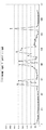
図14は、DWTの詳しい手順を示している。また、図15は、実際の速度データにDWT及びIDWTを適用した例を示している。図15では、図15(a)に示すように、24.11m間隔で計測された64(=26)個の速度データがサンプリングデータとして抽出されており、その原データを図15(b)に示している。また、図16には、この原データのグラフを実線で示している。
【0035】
まず、このサンプリングデータを逆数に変換し、この逆数が1以上の値を取るように、定数を乗算する(ステップ270)。定数の乗算は、後の処理で小数点以下を四捨五入したときに整数値となり得るようにするためであり、定数として例えば1000、あるいは5000を乗算する。この定数が大きければ大きい程、情報の劣化は小さくなり、どんな速度でも表現可能になる。この定数が小さいと、高速域の情報が粗くなる。図15(c)には、逆数に5000を乗算したサンプリングデータを示している。また、図17には、この定数を乗算した逆数のグラフを実線で示している。
【0036】
次に、この逆数に変換したデータの絶対値を小さくするため、データの最大値と最小値との間の中間値を基準(0)に設定して、全てのデータのレベルを中間値分だけシフトする(ステップ271)。図15では、中間値として1700を設定し、図15(c)の値から1700を減算している(図15(d))。
次に、DWTを施す次数Nを決定する。サンプリングデータの個数が2m個の場合には、次数Nは最大でmまで設定することができる(ステップ272)。図15の場合、サンプリングデータが26個であるため、次数の最大は6とすることができる。
【0037】
次いで、n=0に設定し(ステップ273)、サンプリングデータ数/2nにより入力データ数を決定し(ステップ274)、サンプリングデータに対し、前述する(数8)及び(数9)によるDWTを適用して、入力データから1次のスケーリング係数と1次のウェーブレット係数とを生成する(ステップ275)。図15の場合、n=0としたときの入力データ数は64個であり、この64個のデータにDWTを施すことにより、入力データ数の1/2である32個の1次スケーリング係数と、32個の1次ウェーブレット係数とが生成される。
【0038】
得られたスケーリング係数をデータの前方に、ウェーブレット係数をデータの後方に格納する(ステップ276)。図15に示すように、64個のデータを縦に配列する場合では、上位32個のデータが1次スケーリング係数、下位32個のデータが1次ウェーブレット係数となる。
nとNとを比べて、n<Nである場合は(ステップ277)、ステップ274に戻り、次数を1つ上げて、データ数/2nにより入力データ数を決定する。このとき、ステップ276で前方に格納されたスケーリング係数だけが次の入力データとなる。図15の場合、2次のDWTでは、32個の1次(n=1)のスケーリング係数が入力データとなり、これらのデータから2次のDWTにより、16個の2次スケーリング係数と、16個の2次ウェーブレット係数とが生成され、スケーリング係数がデータの前方に、ウェーブレット係数がその後方に格納される。
【0039】
ステップ274〜ステップ276の処理は、n=Nに達するまで繰り返される(ステップ277)。図15の場合、N=6に設定すると、3次のDWTでは、16個の2次スケーリング係数が入力データとなり、このデータから3次のDWTにより、8個の3次スケーリング係数と、8個の3次ウェーブレット係数とが生成され、4次のDWTでは、8個の3次スケーリング係数が入力データとなり、このデータから4次のDWTにより、4個の4次スケーリング係数と、4個の4次ウェーブレット係数とが生成され、5次のDWTでは、4個の4次スケーリング係数が入力データとなり、このデータから5次のDWTにより、2個の5次スケーリング係数と、2個の5次ウェーブレット係数とが生成され、6次のDWTでは、2個の5次スケーリング係数が入力データとなり、このデータから6次のDWTにより、1個の6次スケーリング係数と、1個の6次ウェーブレット係数とが生成される。
【0040】
図15(e)は、6次までのDCTによって生成されたデータを示しており、上から順に、1個の6次スケーリング係数、1個の6次ウェーブレット係数、2個の5次ウェーブレット係数、4個の4次ウェーブレット係数、8個の3次ウェーブレット係数、16個の2次ウェーブレット係数及び32個の1次ウェーブレット係数が並んでいる。
【0041】
次いで、DWT符号化処理部34は、生成したスケーリング係数及びウェーブレット係数を、量子化決定部32が決定した交通情報量子化テーブル53を用いて量子化する(ステップ278)。交通情報量子化テーブル53には、スケーリング係数を除する値p及びウェーブレット係数を除する値q(≧p)が規定されており、量子化処理では、スケーリング係数をpで、ウェーブレット係数をqで割り算し、四捨五入してデータを丸める(ステップ279)。なお、この量子化を省略し(p=q=1とした場合に相当する)、丸め処理だけを行うようにしても良い。また、量子化の代わりに、スケーリング係数及びウェーブレット係数に所定の整数を乗算する逆量子化を行っても良い。
【0042】
図15では、図15(a)に規定された量子化サンプル値1でスケーリング係数及びウェーブレット係数を除し、小数点以下を丸め処理して、図15(f)の整数値を得ている。ステップ270においてサンプリングデータの逆数に乗算した定数が小さいと、この整数値が小さくなり、丸めによる影響が大きく現れるため、情報の精度が低下する。
ただ、定数が大き過ぎると、伝送データ量が多くなる。この丸めに依る影響は、整数値が小さい場合、つまり、速度が大きい場合に大きく現れるが、一般道など元々制限速度が40km/hに設定されている道路では、 40km/h以上のデータを正確に把握する必要はない。こうした点を考慮して、速度の逆数に乗算する定数を決める必要がある。また、高速道路では、制限速度が80km/hと高速になるので、道路種別や道路規制に応じて、この定数値を変化させるようにしても良い。
【0043】
図11に戻り、DWT符号化処理部34は、量子化(または逆量子化)したデータを、量子化決定部32が決定した符号表52を用いて可変調符号化する(ステップ29)。なお、この可変長符号化も、省略することができる。
DWT符号化処理部34は、これらの処理を交通情報提供区間の全てについて実行する(ステップ30、ステップ31)。
情報送信部35は、符号化されたデータを送信データに変換し(ステップ32)、符号表とともにデータ送信する(ステップ33)。
【0044】
図18は、交通情報送信部30から送信されるデータのデータ構成例を示している。図18(a)は、交通情報の対象道路区間を表す形状ベクトルデータ列である。図18(b)は、各対象道路区間のスケーリング係数だけを集めた交通情報データ列であり、DWT最終次数NにおけるN次スケーリング係数が記述されている(なお、サンプリングデータ数がk×2N個の場合、N次スケーリング係数はk個となる)。
図18(c)は、各対象道路区間のウェーブレット係数だけを集めた交通情報データ列であり、DWTの各次数におけるウェーブレット係数が記述されている。情報送信部35は、形状ベクトルデータ列の情報(図18(a))とともに、各対象道路区間のスケーリング係数を記述した交通情報(図18(b))を送信し、次いで、ウェーブレット係数に関する交通情報(図18(c))をDWTの次数が高い順に送信する。
【0045】
一方、受信側装置60は、図11に示すように、情報受信部61がデータを受信すると(ステップ41)、各交通情報提供区間Vについて(ステップ42)、復号化処理部62が、形状ベクトルを復号化し、マップマッチング及び区間確定部63が、自己のデジタル地図データベース65に対するマップマッチングを行い、対象道路区間を特定する(ステップ43)。また、復号化処理部62は、符号表を参照して、速度情報データの可変長復号化(ステップ44)や逆量子化(送信側で逆量子化を行っている場合には量子化)を行う(ステップ45)。図15(g)は、受信側で逆量子化した速度情報のデータを示している。
【0046】
復号化処理部62は、逆量子化で得られたデータにIDWTを実施する(ステップ46)。
図19は、IDWTの詳しい手順を示している。受信した速度情報のデータからDWTの次数Nを読み取り(ステップ461)、nをN−1に設定し(ステップ462)、データ数/2nにより入力データ数を決定する(ステップ463)。次いで、入力データの前方をスケーリング係数とし、入力データの後方をウェーブレット係数として、(数10)及び(数11)によってデータを再構成する(ステップ464)。
【0047】
図15の場合、N=6であるため、入力データ数は、64/25により2個となり、受信した1個の6次スケーリング係数と1個の6次ウェーブレット係数とから、2個の5次スケーリング係数が再構成される。
n>0である場合、または制限時間内である場合は、ステップ463に戻り、nを1減算して、ステップ463、ステップ464の手順を繰り返す(ステップ465)。図15の場合、時間による制限が無いものとすると、生成された2個の5次スケーリング係数と、受信した2個の5次ウェーブレット係数とから4個の4次スケーリング係数を生成し、この4個の4次スケーリング係数と、受信した4個の4次ウェーブレット係数とから8個の3次スケーリング係数を生成し、この8個の3次スケーリング係数と、受信した8個の3次ウェーブレット係数とから16個の2次スケーリング係数を生成し、この16個の2次スケーリング係数と、受信した16個の2次ウェーブレット係数とから32個の1次スケーリング係数を生成し、この32個の1次スケーリング係数と、受信した32個の1次ウェーブレット係数とから64個のデータを復元する。図15(h)は、6回のIDWTを繰り返して復元された速度データを示している。
【0048】
n=0となり、IDWTが終了したときは、送信側がレベルシフトした分だけデータを逆シフトする(ステップ468)。図15(i)は、逆シフトを終えた復元データを示している。また、図17には、この復元データのグラフを点線で示している。復元データは原データと殆ど重なっている。
また、予め規定された制限時間が過ぎたときは、n>0であってもIDWTを終了し、それまでに得られた速度データを用いて解像度を落とした速度情報を表示するため、距離量子化単位の単位長(距離分解能)を2n倍に設定し(ステップ467)、さらに、送信側がレベルシフトした分だけデータを逆シフトする(ステップ468)。
【0049】
受信側装置60は、制限時間を超えたために、図15(f)の送信データの一部しか受信できなかった場合でも、解像度を落とした速度情報を復元することができる。6次スケーリング係数しか受信できなかった場合は、原データの距離解像度の1/26=1/64のデータが復元できる。
それに加えて6次ウエーブレット係数が受信できたときは、受信済みデータと組み合わせてIDWTを行うことにより、5次スケーリング係数が復元できるため、原データの距離解像度の1/25=1/32のデータが再現できる。
それに加えて5次ウエーブレット係数が受信できたときは、受信済みデータと組み合わせてIDWTを行うことにより、4次スケーリング係数が復元できるため、原データの距離解像度の1/24=1/16のデータが再現できる。
それに加えて4次ウエーブレット係数が受信できたときは、受信済みデータと組み合わせてIDWTを行うことにより、3次スケーリング係数が復元できるため、原データの距離解像度の1/23=1/8のデータが再現できる。
それに加えて3次ウエーブレット係数が受信できたときは、受信済みデータと組み合わせてIDWTを行うことにより、2次スケーリング係数が復元できるため、原データの距離解像度の1/22=1/4のデータが再現できる。
それに加えて2次ウエーブレット係数まで受信できたときは、受信済みデータと組み合わせてIDWTを行うことにより、1次スケーリング係数が復元できるため、原データの距離解像度の1/2のデータが再現できる。
それに加えて1次ウエーブレット係数が受信できたときは、受信済みデータと組み合わせてIDWTを行うことにより、原データの距離解像度のデータが復元できる。
こうした受信側での復元を容易にするため、送信側は、スケーリング係数、次数の高いウェーブレット係数、次数の低いウェーブレット係数の順にデータを送信する。
【0050】
復号化処理部62は、復元したデータの逆数を取り、送信側で乗算された定数を乗算して速度情報を再生する(ステップ47)。図15(j)は、復元した速度データを示している。図16には、この復元した速度データのグラフを「ウェーブレット変換(1)速度」と表示して示しているが、原データに重なり、区別できない。また、図16には、N次〜1次の階層のデータを用いて復元した復元データを「ウェーブレット変換(2)速度」と表示して点線で示し、N次〜2次の階層のデータを用いて復元した復元データを「ウェーブレット変換(3)速度」と表示して一点鎖線で示している。
【0051】
交通情報反映部64は、復元された速度情報を自システムのリンクコスト等に反映させる(ステップ48)。こうした処理が全ての交通情報提供区間について実行される(ステップ49、50)。情報活用部67は、提供された速度情報を活用して所要時間表示やルート検索などを実行する(ステップ51)。
このように、DWTを施したデータは階層性を有しており、受信側では、一部の階層のデータしか利用できない場合でも、低分解能の速度情報を復元することができる。また、この場合、速度情報の原データの逆数を取り、これに定数を乗算してDWT処理を施しているため、一部の階層のデータのみを利用した速度情報であっても、ドライバーが体感する混雑状況にマッチした値を復元することができる。
【0052】
図5及び図6に示すグラフは、比較のため、速度情報の原データに、逆数への変換を行わずにDWT処理を施した場合の復元データを示している。図16と図5及び図6とを比較して明らかなように、速度情報の逆数を取ってDWTを施した場合(図16)は、逆数への変換を行わない場合(図5及び図6)に比べて、一部の階層のデータだけで復元した復元データが、低い値を取る。この傾向は、図16の楕円領域Aに良く現れている。
このように、速度情報の逆数を取ってDWT処理を行うことにより、平均速度は低い値に引っ張られるが、この平均速度はドライバーが体感する速度に、より近いものとなる。
【0053】
また、図20は、原データの逆数に乗算する定数を、図16の場合の50分の1(即ち、100)に設定した場合の原データと復元データとを示している。原データの逆数に乗算する定数を小さくすると、楕円領域B及びCで示す高速域の情報は非常に粗くなるが、楕円領域Aで示す低速域の復元データは原データと良く一致している。交通混雑情報として関心が高いのは、走行速度が遅い場合であって、一般道の制限速度に近い速度、あるいはそれ以上の速度についての詳しい情報は、必ずしも必要としない。こうした点を考慮すると、原データの逆数に乗算する定数を100にしても、十分実用的な速度情報を復元できる。また、前述するように、道路種別や道路規制に応じて、この定数値を変化させるようにしても良い。
【0054】
このように、DWTを施したデータは階層性を有しており、全ての階層のデータを用いてロスレス圧縮(可逆変換)を行うこともできれば、一部の階層のデータだけを用いてロッシー圧縮(不可逆変換)を行うこともできる。また、受信側で一部データの欠損した情報しか受信できない場合でも、低分解能の情報を復元させることが可能である。送信側は、通信環境や受信性能を意識することなく、階層別に優先順位を設定して、スケーリング係数→次数の高いウェーブレット係数→次数の低いウェーブレット係数の順に送信すれば、受信側が、受信できたデータに応じて、詳細に、または、粗く、速度情報を再現することができる。
また、速度データを逆数に変換してDWTを実施しているため、一部の階層のデータから速度情報を復元する際に算術平均処理が行われても、復元した速度情報とドライバーの体感混雑度との間にずれは発生しない。
【0055】
なお、これまで、対象道路区間を知らせるために、形状ベクトルデータ列を受信側に伝え、受信側が、この形状ベクトルデータ列を参照して交通情報の対象道路区間を識別する場合について説明したが、道路区間を識別するためのデータ(道路区間参照データ)には、形状ベクトルデータ列以外の使用も可能である。例えば、図21(a)に示すように、統一的に定めた道路区間識別子(リンク番号)や交差点識別子(ノード番号)を用いても良い。
また、提供側及び受信側の双方が同一地図を参照する場合には、提供側が緯度・経度データを受信側に伝え、受信側が、このデータによって道路区間を特定することができる。
【0056】
また、図21(b)に示すように、交差点部やリンク途中の道路から抜き出した間欠的なノードP1・P2・P3・P4の位置参照用の緯度・経度データ(名称、道路種別等の属性情報も保有するもの)を受信側に送信して対象道路を伝えるようにしてもよい。ここで、P1=リンク中点、P2=交差点部、P3=リンク中点、P4=リンク中点である。この場合、受信側は、図21(c)に示すように、まず、P1、P2、P3、P4の各々の位置を特定し、次に各々の区間を経路探索で繋いで、対象道路区間を特定する。
【0057】
また、対象道路を特定する道路区間参照データとして、前述する形状ベクトルデータ列や道路区間識別子、交差点識別子だけでなく、道路地図をタイル状に区分してその各々に付した識別子や、道路に設けたキロポスト、道路名、住所、郵便番号等を用い、これらの道路区間参照データによって、交通情報の対象道路区間を特定してもよい。
【0058】
(第2の実施形態)
本発明の第2の実施形態では、交通情報に含まれるノイズを除去する方法について説明する。
交通情報では、渋滞や混雑の発生状況を知らせる低速域の状態量の詳しい情報は有用であるが、高速域の状態量に関する詳しい情報は、不要であり、伝送データ量を徒に増やすだけのノイズでしかない。
高分解能で交通情報を表現する生データには、こうしたノイズが含まれる。このノイズは、データの送信側で除去し、受信側ではノイズの有無を考慮せずに復号処理ができるようにする。
【0059】
この実施形態の方法では、速度データを逆数に変換し、DWTを施してスケーリング係数とウェーブレット係数とを生成し、これらのデータを受信側に送信する際に、絶対値の小さいウェーブレット展開係数をノイズ成分と見做し、0値として扱う。
この絶対値の小さいウェーブレット展開係数の0値化で影響を受けるのは高速域の速度データだけであり、低速域の速度データは影響を受けない。
【0060】
図22は、このノイズ除去の手順を含めた速度情報のDWT圧縮のフローチャートを示している。図14のステップ270からステップ279の手順により、逆数に変換した速度データにDWTを施してスケーリング係数及びウェーブレット係数を生成し、この内、絶対値の小さいウェーブレット係数を切り捨てる(ステップ280)。
ステップ280でのデータの切捨て(0値化)は、速度データの逆数を表示した図23のグラフにおいて、楕円領域D、E、Fに含まれる高速域の細かな速度の動きをノイズとして除くものであり、そのため高速域のデータは、影響を受ける。しかし、楕円領域Gで示す低速域のデータは、全く影響を受けない。
【0061】
図24には、原データの速度情報を実線で示し、絶対値の小さいウェーブレット係数を除去(0値化)したデータを用いて復元した速度情報を点線で示している。この図から明らかなように、高速域のデータの精度は粗くなるが、交通混雑情報として関心が高い低速域のデータは、原データを忠実に再現している。
一方、伝送データ量について見ると、絶対値の小さいウェーブレット係数をすべて0値化することにより、図11のステップ29での可変調符号化で、データ量は大幅に削減される。
このように、速度データを逆数に変換してDWT処理を行う交通情報提供方法では、絶対値の小さいウェーブレット展開係数を0値化することにより、ノイズ成分を除去し、データ量の削減を図ることができる。
【0062】
(第3の実施形態)
本発明の第1及び第2の実施形態では、センターである交通情報提供装置が、車載機などの交通情報利用装置に交通情報を提供する場合について説明したが、走行データを提供するプローブカーの車載機が交通情報提供装置となり、プローブカーの情報を収集するセンターが交通情報利用装置となるシステムにおいても、本発明の交通情報提供方法の適用は可能である。本発明の第3の実施形態では、このシステムについて説明する。
【0063】
このシステムは、図25に示すように、走行時のデータを計測して提供するプローブカー車載機90と、このデータを収集するプローブカー収集システム80とから成り、プローブカー車載機90は、送信データの符号化に用いる符号表をプローブカー収集システム80から受信する符号表受信部94と、速度を検知するセンサA106と、センサA106の検知情報を収集するセンサ情報収集部98と、GPSアンテナ101での受信情報やジャイロ102の情報を用いて自車位置を判定する自車位置判定部93と、自車の走行軌跡やセンサA106が検知した速度情報を蓄積する走行軌跡計測情報蓄積部96と、速度情報のサンプリングデータを生成する計測情報データ変換部97と、速度データの逆数にDWTを施してスケーリング係数とウェーブレット係数とに変換し、このスケーリング係数及びウェーブレット係数や走行軌跡データを、受信した符号表データ95を用いて符号化するDWT符号化処理部92と、符号化されたデータをプローブカー収集システム80に送信する走行軌跡送信部91とを備えている。
【0064】
一方、プローブカー収集システム80は、プローブカー車載機90から速度情報や走行軌跡情報を受信する走行軌跡受信部83と、符号表データ86を用いて受信データの復号化を行う符号化データ復号部82と、スケーリング係数及びウェーブレット係数にIDWTを施し、逆数変換処理して速度情報を復元する計測情報データ逆変換部87と、復元された速度情報や走行軌跡のデータを活用する走行軌跡計測情報活用部81と、プローブカーの現在位置に応じてプローブカー車載機90に与える符号表を選出する符号表選出部85と、選出された符号表をプローブカーに送信する符号表送信部84とを備えている。
【0065】
プローブカー車載機90の自車位置判定部93は、GPSアンテナ101での受信情報やジャイロ102の情報を用いて自車位置を識別する。また、センサ情報収集部98は、センサA106で検知された速度情報の計測値を収集する。集められた速度情報は、自車位置判定部93が識別した自車位置と対応付けて走行軌跡計測情報蓄積部96に格納される。
計測情報データ変換部97は、走行軌跡計測情報蓄積部96に蓄積された速度情報を走行道路の計測開始地点(基準位置)からの距離の関数で表し、速度情報のサンプリングデータを生成する。DWT符号化処理部92は、このサンプリングデータの逆数にDWTを施して、速度情報をスケーリング係数とウェーブレット係数とに変換し、走行軌跡データや変換したスケーリング係数及びウェーブレット係数を、受信した符号表データ95を用いて符号化する。符号化された走行軌跡データ及び速度情報は、プローブカー収集システム80に送られる。このとき、プローブカー車載機90は、速度情報を、スケーリング係数→次数の高いウェーブレット係数→次数の低いウェーブレット係数の順に送信する。
【0066】
データを受信したプローブカー収集システム80では、符号化データ復号部82が、符号化されている走行軌跡データ及び速度情報を、符号表データ86を用いて復号化する。計測情報データ逆変換部87は、復号化されたスケーリング係数及びウェーブレット係数にIDWTを施し、逆数に変換して速度情報を復元する。走行軌跡計測情報活用部81は、復元された速度情報を、プローブカーが走行した道路の交通情報の作成に利用する。
このように、本発明の交通情報提供方法は、プローブカー車載機からアップロードする情報に対しても適用することができる。車載機のデータ処理能力や伝送容量が不足し、プローブカー車載機から、スケーリング係数及び一部のウェーブレット係数しか送信できない場合でも、プローブカー収集システムは、受信できた情報から、プローブカーが走行した道路での大まかな速度情報を復元することができる。
【0067】
なお、各実施形態のシステムでは、提供する交通情報のデータをビットプレーン分解して送信するようにしても良い。ビットプレーン分解は、データを二進数で表し、全てのデータのMSB、2ビット目、3ビット目、LSBと言う順序で桁の大きいビットデータから順次送信する。この場合、受信側では、情報の受信途中で大まかな交通状況を表示することが可能になる。
【0068】
【発明の効果】
以上の説明から明らかなように、本発明の交通情報提供方法は、通信環境や受信能力により、提供された速度情報の一部しか受信側で受信できない場合でも、また、送信側の送信能力の不足から一部の階層のデータしか送られて来ない場合でも、受信側において、速度情報を粗い分解能で近似的に再現することを可能にする。そして、この場合に、ドライバーが体感する混雑度とずれが無い速度情報を復元することができる。
また、速度情報から、情報価値が無いノイズを減らして、速度情報のデータ量を削減することができる。
【0069】
また、本発明の交通情報提供システムでは、速度情報の提供側が、通信環境や受信状況などを意識せずに速度情報を提供しても、受信側で、受信できた情報の範囲で粗い速度情報や詳細な速度情報を復元することができる。また、提供側は、ノイズを削減した速度情報を提供することができる。
また、本発明の交通情報提供装置及び交通情報利用装置は、このシステムを実現することができる。
【図面の簡単な説明】
【図1】ウェーブレット変換の一般式を示す図
【図2】DWTを実現するフィルタ回路を示す図
【図3】DWTでの信号の分離(a)と、IDWTでの信号の再構成(b)とを示す図
【図4】本発明の第1の実施形態におけるDWT及びIDWTを実現するフィルタ回路を示す図
【図5】原データと1次DWTで生成されるスケーリング係数との関係を示す図
【図6】高次DWTで生成されるスケーリング係数を示す図
【図7】本発明の第1の実施形態における交通情報提供システムの構成を示すブロック図
【図8】プローブカーの計測地点を示す図
【図9】プローブカーの計測データを示す図
【図10】距離の関数で表した速度を示す図
【図11】本発明の第1の実施形態における交通情報提供システムの動作を示すフロー図
【図12】本発明の第1の実施形態における速度情報のサンプリング手順を示すフロー図
【図13】本発明の第1の実施形態における速度データのサンプリングの取り方を示す図
【図14】本発明の第1の実施形態における速度情報のDWT手順を示すフロー図
【図15】本発明の第1の実施形態におけるDWT及びIDWTを適用した具体例を示す図
【図16】本発明の第1の実施形態における速度情報の原データと復元データとを示すグラフ
【図17】本発明の第1の実施形態における速度情報の逆数の原データと復元データとを示すグラフ
【図18】本発明の第1の実施形態における送信データのデータ構造を示す図
【図19】本発明の第1の実施形態における速度情報のIDWT手順を示すフロー図
【図20】本発明の第1の実施形態における速度情報の逆数に小さい定数を乗じたときの復元データを示す図
【図21】道路区間参照データの説明図
【図22】本発明の第2の実施形態におけるDWT手順を示すフロー図
【図23】本発明の第2の実施形態における交通情報提供方法で除去するノイズを説明する図
【図24】本発明の第2の実施形態における速度情報の原データと復元データとを示すグラフ
【図25】本発明の第3の実施形態における交通情報提供システムの構成を示すブロック図
【図26】道路に沿って変化する状態量としての交通情報を説明する図
【図27】提供される交通情報のデータ構造を示す図
【符号の説明】
10 交通情報計測装置
11 センサ処理部A
12 センサ処理部B
13 センサ処理部C
14 交通情報算出部
21 センサA(超音波車両センサ)
22 センサB(AVIセンサ)
23 センサC(プローブカー)
30 交通情報送信部
31 交通情報収集部
32 量子化単位決定部
33 交通情報変換部
34 DWT符号化処理部
35 情報送信部
36 デジタル地図データベース
50 符号表作成部
51 符号表算出部
52 符号表
53 交通情報量子化テーブル
54 距離量子化単位パラメータテーブル
60 受信側装置
61 情報受信部
62 復号化処理部
63 マップマッチング及び区間確定部
64 交通情報反映部
66 リンクコストテーブル
67 情報活用部
68 自車位置判定部
69 GPSアンテナ
70 ジャイロ
71 ガイダンス装置
80 プローブカー収集システム
81 走行軌跡計測情報活用部
82 符号化データ復号部
83 走行軌跡受信部
84 符号表送信部
85 符号表選出部
86 符号表データ
87 計測情報データ逆変換部
90 プローブカー車載機
91 走行軌跡送信部
92 DWT符号化処理部
93 自車位置判定部
94 符号表受信部
95 符号表データ
96 走行軌跡計測情報蓄積部
97 計測情報データ変換部
98 センサ情報収集部
101 GPSアンテナ
102 ジャイロ
106 センサA
181 低域通過フィルタ
182 高域通過フィルタ
183 間引き回路
184 低域通過フィルタ
185 高域通過フィルタ
186 間引き回路
187 加算回路
191 フィルタ回路
192 フィルタ回路
193 フィルタ回路[0001]
TECHNICAL FIELD OF THE INVENTION
The present invention relates to a method for providing traffic information, and a system and apparatus for implementing the method, and more particularly, to a method for accurately providing speed information on traffic flow.
[0002]
[Prior art]
Currently, VICS (Road Traffic Information Communication System), which provides road traffic information providing services to car navigation systems, collects and edits road traffic information, and travels through FM multiplex broadcasting and beacons to indicate traffic congestion information and travel time. It transmits traffic congestion information such as time information (see
In the current VICS information, the current traffic information is expressed as follows.
Traffic congestion conditions include traffic congestion (general road: ≤ 10 km / h, highway: ≤ 20 km / h), congestion (general road: 10-20 km / h, highway: 20-40 km / h), and quiet (general road) : ≧ 20km / h ・ Highway: ≧ 40km / h). If information cannot be collected due to uncollected information or failure of the vehicle detector, “unknown” is displayed. .
The traffic congestion information indicating the traffic congestion state is such that when the entire VICS link (the position information identifier used in VICS) is in the same congestion state,
"VICS link number + status (congestion / congestion / quiet / unknown)"
Is displayed, and only part of the link is congested,
"VICS link number + congestion start distance (distance from link start end) + congestion end distance (distance from link start end) + state (congestion)"
Is displayed. In this case, when the congestion starts from the link start end, the congestion head distance is displayed as 0xff. When different congestion states coexist in a link, each congestion state is described by this method.
Also, the link travel time information indicating the travel time of each link is:
"VICS link number + travel time"
Is displayed.
Further, as prediction information indicating a future change tendency of the traffic condition, an increase / decrease tendency flag indicating four states of “increase tendency / decrease tendency / no change / unknown” is displayed with the current information.
[0003]
The VICS traffic information specifies a road by a link number and displays the traffic information, and the receiving side of the traffic information grasps the traffic condition of the corresponding road on its own map based on the link number. However, the method that the transmitting side and receiving side share the link number and node number to specify the position on the map requires that the link number and node number be newly established or modified every time a new road is changed or changed. Accordingly, since the digital map data of each company must be updated, a large social cost is required for the maintenance.
In order to improve these points and transmit the road position without depending on the VICS link number, the transmitting side arbitrarily sets a plurality of nodes on the road shape, and determines the position of this node in a data string. There is also a method of transmitting a expressed “shape vector data sequence” and performing a map matching on the receiving side using the shape vector data sequence to specify a road on a digital map (see
[0004]
A system for generating traffic information as follows has also been proposed.
First, as shown in FIG. 26A, the shape vector (road) at the distance Xm is sampled by dividing the shape vector (road) from the reference node by a unit block length (eg, 50 to 500 m) at equal intervals. ), The average speed of the vehicle passing through each sampling point is determined. In FIG. 26B, the value of the obtained velocity (state quantity) is shown in a frame representing the unit of quantization of the distance between the sampling points.
In this system, the state quantity changing along the road is transmitted to the receiving side as traffic information. At this time, it is necessary to reduce the amount of transmission data. For this purpose, for example, the amount of state is quantized, expressed as a difference from the statistical prediction value, and converted to data unevenly distributed around 0, and this data is converted into a variable length code. Become
[0005]
Alternatively, the state quantity of traffic information (FIG. 26B) that changes along the road is regarded as a function of the distance from the reference node, and is transformed into frequency components by orthogonal transformation, and the coefficient value of each frequency component is received. To provide. The receiving side performs the inverse transformation to reproduce the state quantity of the traffic information.
For conversion to the frequency component, a technique such as FFT (fast Fourier transform) or DCT (discrete cosine transform) can be used. For example, in the Fourier transform, a Fourier coefficient C (k) can be obtained by (Equation 21) (Fourier transform) from a finite number of discrete values (state quantities) represented by a complex function f.
C (k) = (1 / n) Σf (j) · ω-jk (k = 0, 1, 2, ‥, n−1)
(Σ is added from j = 0 to n-1) (Equation 21)
Conversely, given C (k), a discrete value (state quantity) can be obtained by (Equation 22) (inverse Fourier transform).
f (j) = {C (k) · ωjk (j = 0, 1, 2, ‥, n−1)
(Σ is added from k = 0 to n-1) (Equation 22)
The providing side of the traffic information calculates the state quantity of the traffic information (FIG. 26 (b)) using n (= 2) using (Equation 21). N ) Coefficients and quantize these coefficients. In this quantization, a low-frequency coefficient is divided by 1, a higher-frequency coefficient is divided by a larger value, and the quotient is rounded to the nearest decimal point. The value after quantization is compressed by variable length coding and transmitted. The data structure of the traffic information is shown in FIG. This traffic information and the shape vector data string information of the target road shown in FIG. 27A are transmitted to the receiving side.
After receiving the traffic information, the receiving side decodes and inversely quantizes the coefficients, and then reproduces the state quantity of the traffic information using (Equation 22).
[0006]
[Patent Document 1]
JP 2001-19417 A
[0007]
[Patent Document 2]
WO 01/18769 A1
[0008]
[Problems to be solved by the invention]
This traffic information providing method has the following problems.
(1) In the provision of traffic information, when there is a limit to the amount of data that can be held on the receiving side and the amount of transmission data, the data that exceeds the limit is not simply overflown, It is necessary to devise a method of sending traffic information data so that low-level information cannot be displayed but high-priority information can be displayed.
(2) Indices of traffic congestion provided as traffic information include "speed", "unit section travel time", "degree of congestion", and the like. On the traffic information receiving side, the "speed" information is included. It is considered to be the easiest to use for displaying the traffic congestion status and for using it for route calculation. However, when sending "speed" information as a traffic state quantity that changes along the road, multiple state quantities are used to reduce the amount of data due to the limitations of the receiving capacity of the receiving side and the transmission capacity of the transmission path. When the averaging process is performed, there is a problem that a value deviates from the driver's bodily congestion degree.
[0009]
For example, in a section of 100 km, it is assumed that the vehicle travels at 90 km at 100 km / h and travels at 10 km at 4 km / h. The required time at this time is 3.4 hours [= (90 ÷ 100) + (10 ÷ 4)], and the average speed in this section is 29.4 km / h [= 100 ÷ 3.4].
On the other hand, if the speed value in this section is simply smoothed (averaged), it becomes 90.4 km / h [= (100 × 90 + 4 × 10) ÷ (90 + 10)]. The required time when traveling in a section of 100 km at this average speed is 1.11 hours. That is, simply averaging the speed values results in a value that deviates from the degree of congestion of the driver.
[0010]
The present invention addresses such a problem. Even if the transmitting side transmits speed information as traffic information without considering the communication environment and the receiving state, the receiving side selects the fineness of the information to be restored. It is an object of the present invention to provide a traffic information providing method capable of transmitting speed information without deviating from a driver's feeling of congestion, and a system and an apparatus for implementing the method. .
[0011]
[Means for Solving the Problems]
Therefore, in the traffic information providing method of the present invention, a discrete wavelet transform is performed on the reciprocal of the speed information expressed as a function of the distance from the reference position on the road, and the reciprocal of the speed information is converted into a scaling coefficient and a wavelet coefficient. I try to provide.
On the receiving side, if the scaling coefficient can be received, the speed information can be approximately restored even if only a part of the wavelet coefficient can be received. In the discrete wavelet transform, approximation is performed by averaging the original data. In the traffic information providing method of the present invention, the inverse of the speed information (= representing the travel time per unit distance) is applied to the wavelet transform. Therefore, the arithmetic average has validity, and can reproduce speed information that does not deviate from the congestion degree experienced by the driver.
[0012]
Also, in the present invention, sampling data is generated from speed information expressed as a function of a distance from a reference position on a road, and a discrete wavelet transform is performed once or plural times on the reciprocal of the sampling data to obtain the reciprocal of the speed information. A traffic information providing device that converts the data into scaling coefficients and wavelet coefficients, and performs one or more inverse discrete wavelet transforms on the scaling coefficients and the wavelet coefficients received from the traffic information providing device, and obtains the reciprocal of the obtained value. The traffic information providing system is constituted by a traffic information utilization device that converts the speed information into the traffic information and restores the speed information.
In this system, even if the traffic information providing device provides the scaling coefficient and the wavelet coefficient without being conscious of the communication environment and the receiving condition, the receiving side may obtain coarse speed information or detailed information within the range of the received information. The speed information can be restored, and the restored speed information matches well with the degree of congestion felt by the driver.
[0013]
Further, in the present invention, the traffic information providing device includes a traffic information conversion unit that generates 2N-th sampling data or a multiple of 2N-th sampling data from the collected speed information data, Traffic information coding means for performing one or more discrete wavelet transforms on the reciprocal to convert the reciprocals into scaling coefficients and wavelet coefficients; and transmitting the scaling coefficients prior to the wavelet coefficients. Traffic information transmitting means for transmitting the coefficient before the wavelet coefficient of a lower order is provided.
Therefore, on the receiving side, if the scaling coefficient can be received, the speed information represented by the coarse resolution can be restored even if only a part of the wavelet coefficient can be received.
[0014]
Further, in the present invention, the traffic information utilization device includes, from the traffic information providing device, traffic section receiving data for receiving the road section reference data representing the target road of the speed information and the scaling coefficient and the wavelet coefficient as the speed information; Target road determining means for specifying a target road of speed information using data; performing one or more inverse discrete wavelet transforms on a scaling coefficient and a wavelet coefficient; converting the obtained value into a reciprocal number to restore speed information Traffic information decoding means for performing the traffic information decoding.
In this apparatus, a target section of speed information is specified from received information by map matching or the like, and the speed information is restored by performing inverse discrete wavelet transform and inverse transform.
[0015]
BEST MODE FOR CARRYING OUT THE INVENTION
(1st Embodiment)
<Discrete wavelet transform>
In the traffic information providing method of the present invention, the transmitting side converts the provided speed information (V) into a reciprocal (1 / V), performs a discrete wavelet (Wavelet) transform (DWT), compresses the transmitted information, and transmits the resultant data. The receiving side decompresses the received speed information by an inverse discrete wavelet transform (IDWT), converts the speed information into its inverse, and then displays or uses the information.
DWT is a data compression method used for image compression and audio compression. FIG. 1 shows a general equation of the wavelet transform.
[0016]
A wavelet is an operation (scale conversion) of multiplying a function Ψ (t), which is called a basic wavelet, which exists only in a limited range in terms of time and frequency, on the time axis (scale conversion), and a method in which time b This means a set of functions such as (Equation 3), which is obtained by performing an operation of shifting the image only horizontally (shift conversion). Using this function, the frequency and time components of the signal corresponding to the parameters a and b can be extracted, and this operation is called wavelet transform.
The wavelet transform includes a continuous wavelet transform and a discrete wavelet transform (DWT). The forward transform of the continuous wavelet transform is shown in (Equation 1), and the inverse transform is shown in (Equation 2). Letting these real numbers a and b be a = 2j and b = 2jk (j> 0), the forward transform of the discrete wavelet transform (DWT) is as shown in (Equation 5), and the inverse transform (IDWT) is (Equation 5). It is represented as 6).
[0017]
This DWT can be realized by a filter circuit that recursively divides the low frequency band, and the IDWT can be realized by a filter circuit that repeats synthesis reverse to that at the time of division. FIG. 2A shows a DWT filter circuit. This DWT circuit is configured by a cascade connection of a plurality of
FIG. 3A shows signals decomposed by the
[0018]
The following (Equation 8) and (Equation 9) show DWT conversion equations used in the embodiment of the present invention.
Step 1: w (t) = f (2t + 1) − [{f (2t) + f (2t + 2)} / 2] (Equation 8)
Step 2: s (t) = f (2t) + [{w (t) + w (t-1) +2} / 4] (Equation 9)
In the n-th order forward conversion, the (n-1) -th scaling coefficient is converted by the steps of (Equation 8) and (Equation 9). FIG. 4A shows the configuration of each of the
[0019]
FIG. 2B shows an IDWT filter circuit. The IDWT circuit includes an
FIG. 3B shows a signal reconstructed by the
[0020]
The following (Equation 10) and (Equation 11) show the conversion formula of IDWT used in the embodiment of the present invention.
Step 1: f (2t) = s (t) + [{w (t) + w (t-1) +2} / 4] (Equation 10)
Step 2: f (2t + 1) = w (t) − [{f (2t) + f (2t + 2)} / 2] (Equation 11)
In the n-th order inverse transformation, the signal transformed by the (n + 1) -th order IDWT is used as a scaling coefficient to perform transformation by the steps of (Equation 10) and (Equation 11). FIG. 4B shows the configuration of each
[0021]
<Significance of reciprocal of speed data>
FIG. 5 shows the original data (solid line) and the primary scaling factor (dotted line) obtained by performing one DWT on the original data. FIG. 6 shows the primary scaling factor. Along with the (dotted line), a second-order scaling coefficient (dot-dash line) and a third-order scaling coefficient (a long dotted line) when DWT is further repeated are shown.
The result of smoothing the change in the original data is the scaling factor. The DWT is repeated, and the higher the scaling factor, the more the smoothing proceeds. The scaling coefficient approximately represents the original data, and the rough state of the original data can be known from the scaling coefficient. Therefore, if the receiving side cannot receive all the data transmitted by the transmitting side when the receiving capacity or the transmission capacity is insufficient, if the data that can restore a certain level of the scaling coefficient is obtained, the scaling coefficient is restored. By doing so, changes in the original data can be roughly reproduced.
[0022]
The distance quantization unit of the primary scaling coefficient is twice the distance quantization unit of the original data, and the value of this scaling coefficient is an average of the values of the original data included in the distance quantization unit. It has become. Further, the distance quantization unit of the secondary scaling coefficient is twice the distance quantization unit of the primary scaling coefficient, and the value of the secondary scaling coefficient is the primary quantization coefficient included in the distance quantization unit. The value of the scaling coefficient is averaged. That is, the distance quantization unit of the n-th scaling coefficient is twice the distance quantization unit of the (n-1) -th scaling coefficient, and the value of the n-th scaling coefficient is included in the distance quantization unit. (N-1) -th order scaling coefficient is averaged.
However, if the original data is speed data, as described above, a value obtained by simply arithmetically averaging the speed data is far from the degree of congestion felt by the driver.
Therefore, in the present invention, the reciprocal (1 / V) of the speed data (V) is obtained, and DWT is applied to the reciprocal. In this case, since the reciprocal (1 / V) of the speed data represents the travel time per unit distance, the arithmetic average has validity.
[0023]
<Traffic information providing system>
FIG. 7 shows an example of the traffic information providing system in this embodiment. This system uses a traffic
[0024]
The traffic
The code
The traffic
[0025]
The receiving
[0026]
The sensor processing unit A11 and the sensor-processing unit B12 of the traffic
[0027]
The flow chart of FIG. 11 shows the operation of the code
The code
When creating the code table, the traffic information (speed information) of the past traffic situation pattern L is totaled (step 11), and the quantization unit (distance quantization) in the distance direction described in the distance quantization unit parameter table 54 is calculated. (Quantization unit), a distance quantization unit M to be used is set (step 12), and a traffic information quantization table N used for quantization of scaling coefficients and wavelet coefficients is set from the traffic information quantization table 53. (Step 13). Next, a value at each sampling point for each interval M is calculated from the traffic information of the traffic situation pattern L, a reciprocal of this value is calculated, and DWT is performed on the reciprocal to obtain a scaling coefficient and a wavelet coefficient (step 14). The details will be described in detail in the procedure of the traffic
[0028]
Next, the scaling coefficient and the wavelet coefficient are quantized using the value specified in the traffic information quantization table N, and the quantization coefficient of the scaling coefficient and the wavelet coefficient is calculated (step 15). Next, the distribution of the quantized coefficients is calculated (step 16), and based on the quantized coefficients and the run length distribution (continuous distribution of the same value), the quantized coefficients of the scaling coefficients and wavelet coefficients are variable-length coded. A code table 52 is created (step 17) and (step 18).
This procedure is repeated until the code table 52 corresponding to all combinations of L, M, and N is created (step 19).
In this way, a large number of code tables 52 corresponding to various traffic situation patterns and resolutions of information expression are created and held in advance.
[0029]
On the other hand, the traffic
The quantization
[0030]
When determining the position resolution, the following points are considered.
In an existing system, a resolution (for example, 10 m) determined as a unit for collecting information such as travel time may be used.
-For routes far from the information transmission position, the distance resolution can be coarsened in advance according to the importance.
-Since the speed information collected from the probe car does not represent important information (traffic end, head, etc.) as traffic information in the raw data itself, the position resolution is determined depending on the number of data. You may.
-When performing data compression by FFT (Fast Fourier Transform), the number of data is 2 N However, when DWT is performed, the number of data is 2 N Or 2 N (Ie, k × 2 N (K and N are positive integers). (Note that from the distance resolution, the data is k × 2 N If the number of data is not equal to “0” or an appropriate value (eg, the last value of valid data), the number of data is k × 2. N Until you have
[0031]
In determining the resolution of the speed information, the following points are taken into consideration.
-Consider the speed measurement accuracy and set the resolution so that it is an integral multiple of the accuracy.
-It is also possible to make the resolution of a route with low importance lower than that of an important route in advance.
・ When sampling, round the data according to the resolution.
The final position resolution and resolution of the speed information are determined according to the transmission order and transmission capacity according to the importance of the data on the transmission side, and the data reception amount and processing speed on the reception side.
[0032]
The traffic
FIG. 12 shows a detailed setting procedure of sampling data of speed information, and FIG. 13 shows sampling data (dotted line) determined from speed information (solid line) collected by the probe car.
The speed information is expressed as a function of distance by the traffic information calculation unit 14 (step 261), and the unit division length (resolution of position) of the distance quantization unit or the number of data is defined by the quantization unit determination unit 32 ( Step 262). The traffic
The quantization
FIG. 13 shows a case where the original data is rounded (rounded) to obtain sampling data in units of 10 km / h.
[0033]
Next, the traffic
In the case of FIG. 13, the number of data is 8 (= 2 3 ), No sampling data is added.
[0034]
Returning to FIG. 11, the DWT encoding processing unit 34 calculates the reciprocal of the sampling data, and performs DWT on the reciprocal (step 27).
FIG. 14 shows a detailed procedure of the DWT. FIG. 15 shows an example in which DWT and IDWT are applied to actual speed data. In FIG. 15, 64 (= 2) measured at 24.11 m intervals as shown in FIG. 6 ) Pieces of speed data are extracted as sampling data, and the original data is shown in FIG. FIG. 16 shows a graph of the original data by a solid line.
[0035]
First, this sampling data is converted into a reciprocal, and a constant is multiplied so that the reciprocal takes a value of 1 or more (step 270). The constant multiplication is performed so that an integer value can be obtained when the decimal part is rounded off in the subsequent processing. For example, 1000 or 5000 is multiplied as a constant. The larger the constant, the less the information degradation and the more expressible it is at any speed. If this constant is small, the information in the high speed range becomes coarse. FIG. 15C shows sampling data obtained by multiplying the reciprocal by 5000. FIG. 17 shows a graph of a reciprocal obtained by multiplying the constant by a solid line.
[0036]
Next, in order to reduce the absolute value of the data converted to the reciprocal, an intermediate value between the maximum value and the minimum value of the data is set as a reference (0), and the levels of all data are set by the intermediate value. The shift is performed (step 271). In FIG. 15, 1700 is set as the intermediate value, and 1700 is subtracted from the value in FIG. 15C (FIG. 15D).
Next, the order N for performing DWT is determined. Number of sampling data is 2 m In this case, the order N can be set up to m at the maximum (step 272). In the case of FIG. 15, the sampling data is 2 6 Therefore, the maximum order can be 6.
[0037]
Next, n = 0 is set (step 273), and the number of sampling data / 2 n The number of input data is determined according to (step 274), and the above-mentioned DWT according to (Equation 8) and (Equation 9) is applied to the sampled data to obtain a first-order scaling coefficient and first-order wavelet coefficient from the input data. Is generated (step 275). In the case of FIG. 15, the number of input data is 64 when n = 0, and DWT is applied to the 64 data to obtain 32 primary scaling coefficients which are の of the number of input data. , 32 primary wavelet coefficients are generated.
[0038]
The obtained scaling coefficient is stored before the data, and the wavelet coefficient is stored after the data (step 276). As shown in FIG. 15, when 64 pieces of data are arranged vertically, the upper 32 pieces of data are primary scaling coefficients, and the lower 32 pieces of data are primary wavelet coefficients.
Comparing n and N, if n <N (step 277), return to step 274, increase the order by one, and reduce the number of data / 2 n To determine the number of input data. At this time, only the scaling coefficient stored ahead in step 276 is the next input data. In the case of FIG. 15, in the secondary DWT, 32 primary (n = 1) scaling coefficients become input data, and from these data, 16 secondary scaling coefficients and 16 secondary scaling coefficients are obtained by the secondary DWT. Are generated, and the scaling coefficient is stored before the data and the wavelet coefficient is stored after the data.
[0039]
[0040]
FIG. 15E shows data generated by DCT up to the sixth order. In order from the top, one sixth-order scaling coefficient, one sixth-order wavelet coefficient, two fifth-order wavelet coefficients, Four quaternary wavelet coefficients, eight tertiary wavelet coefficients, sixteen secondary wavelet coefficients, and thirty-two primary wavelet coefficients are arranged.
[0041]
Next, the DWT encoding processing unit quantizes the generated scaling coefficients and wavelet coefficients using the traffic information quantization table 53 determined by the quantization determining unit 32 (step 278). The traffic information quantization table 53 defines a value p for dividing the scaling coefficient and a value q (≧ p) for dividing the wavelet coefficient. In the quantization process, the scaling coefficient is p and the wavelet coefficient is q. The data is divided and rounded to round the data (step 279). The quantization may be omitted (corresponding to the case where p = q = 1), and only the rounding process may be performed. Further, instead of the quantization, inverse quantization for multiplying the scaling coefficient and the wavelet coefficient by a predetermined integer may be performed.
[0042]
In FIG. 15, the scaling coefficient and the wavelet coefficient are divided by the
However, if the constant is too large, the amount of transmission data increases. The effect of the rounding is large when the integer value is small, that is, when the speed is high. However, on a road such as a general road where the speed limit is originally set to 40 km / h, data with a speed of 40 km / h or more can be accurately obtained. There is no need to figure out. In consideration of these points, it is necessary to determine a constant by which the reciprocal of the speed is multiplied. On a highway, the speed limit is as high as 80 km / h, so this constant value may be changed according to the type of road or road regulation.
[0043]
Returning to FIG. 11, the DWT encoding processing unit 34 performs the variable modulation encoding on the quantized (or inversely quantized) data using the code table 52 determined by the quantization determining unit 32 (step 29). Note that this variable length coding can also be omitted.
The DWT encoding processing unit 34 executes these processes for all the traffic information provision sections (
The
[0044]
FIG. 18 illustrates a data configuration example of data transmitted from the traffic
FIG. 18C is a traffic information data sequence in which only the wavelet coefficients of each target road section are collected, and the wavelet coefficients in each order of the DWT are described. The
[0045]
On the other hand, as shown in FIG. 11, when the information receiving unit 61 receives the data (step 41), the decoding processing unit 62 determines the shape vector as shown in FIG. Is decoded, and the map matching and section determination unit 63 performs map matching on its own digital map database 65 to specify a target road section (step 43). In addition, the decoding processing unit 62 refers to the code table to perform variable length decoding of the speed information data (step 44) and inverse quantization (quantization when inverse quantization is performed on the transmission side). Perform (step 45). FIG. 15 (g) shows data of speed information dequantized on the receiving side.
[0046]
The decoding processing unit 62 performs IDWT on the data obtained by the inverse quantization (step 46).
FIG. 19 shows a detailed procedure of the IDWT. The order N of the DWT is read from the received speed information data (step 461), n is set to N-1 (step 462), and the number of data / 2 n To determine the number of input data (step 463). Next, the data is reconstructed by (Equation 10) and (Equation 11), using the front of the input data as a scaling coefficient and the rear of the input data as a wavelet coefficient (step 464).
[0047]
In the case of FIG. 15, since N = 6, the number of input data is 64/2. 5 , And two fifth-order scaling coefficients are reconstructed from one received sixth-order scaling coefficient and one sixth-order wavelet coefficient.
If n> 0 or within the time limit, the process returns to step 463, decrements n by 1, and repeats the procedures of steps 463 and 464 (step 465). In the case of FIG. 15, assuming that there is no restriction by time, four quaternary scaling coefficients are generated from the generated two quintic scaling coefficients and the received two quintic wavelet coefficients. From the four fourth-order scaling coefficients and the four received fourth-order wavelet coefficients, eight tertiary scaling coefficients are generated. The eight third-order scaling coefficients, the eight received third-order wavelet coefficients, and To generate 32 secondary scaling coefficients from the 16 secondary scaling coefficients and the received 16 secondary wavelet coefficients, and to generate 32 primary scaling coefficients from the 32 primary scaling coefficients. 64 data are restored from the scaling coefficients and the received 32 primary wavelet coefficients. FIG. 15H shows the speed data restored by repeating the IDWT six times.
[0048]
When n = 0 and the IDWT is completed, the data is reversely shifted by the level shifted by the transmitting side (step 468). FIG. 15 (i) shows the restored data after the reverse shift. FIG. 17 shows a graph of the restored data by a dotted line. The restored data almost overlaps with the original data.
When a predetermined time limit has elapsed, the IDWT is terminated even if n> 0, and speed information with reduced resolution is displayed using speed data obtained up to that time. The unit length (distance resolution) of the conversion unit is 2 n The number is doubled (step 467), and the data is reverse-shifted by the level shifted by the transmitting side (step 468).
[0049]
The reception-
In addition, when the sixth-order wavelet coefficient can be received, the fifth-order scaling coefficient can be restored by performing IDWT in combination with the received data. 5 = 1/32 data can be reproduced.
In addition, when the fifth-order wavelet coefficient can be received, the fourth-order scaling coefficient can be restored by performing IDWT in combination with the received data. 4 = 1/16 data can be reproduced.
In addition, when the fourth-order wavelet coefficient is received, the third-order scaling coefficient can be restored by performing IDWT in combination with the received data. 3 = 1/8 data can be reproduced.
In addition, when the tertiary wavelet coefficient can be received, the secondary scaling coefficient can be restored by performing IDWT in combination with the received data. 2 = 1/4 data can be reproduced.
In addition, when the secondary wavelet coefficient can be received, the primary scaling coefficient can be restored by performing IDWT in combination with the received data, so that the data of 1/2 of the distance resolution of the original data can be reproduced. .
In addition, when the primary wavelet coefficient can be received, IDWT is performed in combination with the received data, so that the data of the distance resolution of the original data can be restored.
To facilitate such restoration on the receiving side, the transmitting side transmits data in the order of a scaling coefficient, a higher-order wavelet coefficient, and a lower-order wavelet coefficient.
[0050]
The decoding processing unit 62 obtains the reciprocal of the restored data and reproduces the speed information by multiplying the inverse by the constant multiplied on the transmission side (step 47). FIG. 15 (j) shows the restored speed data. FIG. 16 shows the graph of the restored speed data as “wavelet transform (1) speed”, but the data overlaps with the original data and cannot be distinguished. In FIG. 16, the restored data restored by using the data of the N-th to first-order layers is indicated as a “wavelet transform (2) speed” by a dotted line, and the data of the N-th to second-order layers is shown. The restored data that has been restored by using “wavelet transform (3) speed” is indicated by a dashed line.
[0051]
The traffic information reflecting unit 64 reflects the restored speed information on the link cost of the own system (step 48). Such processing is executed for all traffic information provision sections (steps 49 and 50). The
As described above, the data subjected to the DWT has a hierarchical property, and the receiving side can restore low-resolution speed information even when data of only a part of the hierarchical levels can be used. Also, in this case, since the reciprocal of the original data of the speed information is obtained and multiplied by a constant to perform the DWT processing, even if the speed information uses only the data of a part of the hierarchy, the driver can experience it. It is possible to restore the value that matches the congestion situation.
[0052]
The graphs shown in FIGS. 5 and 6 show restored data obtained by performing DWT processing on the original data of the speed information without performing conversion to the reciprocal for comparison. As is apparent from a comparison between FIG. 16 and FIGS. 5 and 6, when the reciprocal of the speed information is obtained and the DWT is performed (FIG. 16), the conversion to the reciprocal is not performed (FIGS. 5 and 6). ), The restored data obtained by restoring only the data of some layers takes a lower value. This tendency appears well in the elliptical region A in FIG.
As described above, by performing the DWT processing by taking the reciprocal of the speed information, the average speed is pulled to a low value, but this average speed is closer to the speed experienced by the driver.
[0053]
FIG. 20 shows original data and restored data when the constant for multiplying the reciprocal of the original data is set to 1/50 (that is, 100) of FIG. When the constant by which the reciprocal of the original data is multiplied is reduced, the information in the high-speed region indicated by the elliptic regions B and C becomes very coarse, but the restored data in the low-speed region indicated by the elliptical region A matches the original data well. The interest in the traffic congestion information is high when the traveling speed is low, and detailed information on a speed close to or higher than the speed limit of a general road is not necessarily required. Considering these points, sufficiently practical speed information can be restored even if the constant for multiplying the reciprocal of the original data is set to 100. Further, as described above, the constant value may be changed according to the road type or the road regulation.
[0054]
As described above, the data subjected to the DWT has a hierarchical property, and if lossless compression (lossless conversion) can be performed using data of all layers, lossy compression is performed using only data of some layers. (Irreversible transformation) can also be performed. Further, even when the receiving side can receive only information with partial data loss, it is possible to restore low-resolution information. If the transmitting side sets priorities for each layer without regard to the communication environment and receiving performance, and transmits in the order of scaling coefficient → high-order wavelet coefficient → low-order wavelet coefficient, the receiving side can receive Depending on the data, the speed information can be reproduced in detail or coarsely.
In addition, since the DWT is performed by converting the speed data into a reciprocal, even if arithmetic averaging is performed when speed information is restored from data of some layers, the restored speed information and the driver's bodily sensation are congested. There is no deviation from the degree.
[0055]
Heretofore, in order to notify the target road section, the case where the shape vector data string is transmitted to the receiving side, and the receiving side refers to this shape vector data string to identify the target road section of the traffic information, As data for identifying a road section (road section reference data), use other than the shape vector data string is also possible. For example, as shown in FIG. 21A, a united road section identifier (link number) or intersection identifier (node number) may be used.
When both the providing side and the receiving side refer to the same map, the providing side transmits the latitude / longitude data to the receiving side, and the receiving side can specify a road section based on the data.
[0056]
Further, as shown in FIG. 21B, latitude / longitude data (names, attributes of road types, etc.) for intermittent nodes P1, P2, P3, P4 extracted from an intersection or a road in the middle of a link are referred to. (Which also holds information) to the receiving side to inform the target road. Here, P1 = link midpoint, P2 = intersection, P3 = link midpoint, P4 = link midpoint. In this case, the receiving side first specifies the positions of P1, P2, P3, and P4 as shown in FIG. 21 (c), and then connects the sections by a route search to determine the target road section. Identify.
[0057]
In addition, as the road section reference data for specifying the target road, not only the shape vector data string, the road section identifier, and the intersection identifier described above, but also the road map is divided into tiles and the identifiers assigned to each of them are provided. The target road section of the traffic information may be specified by using the road section reference data using the kilopost, the road name, the address, the postal code, and the like.
[0058]
(Second embodiment)
In the second embodiment of the present invention, a method for removing noise included in traffic information will be described.
In traffic information, detailed information on state quantities in the low-speed range that informs of the occurrence of congestion and congestion is useful, but detailed information on state quantities in the high-speed area is unnecessary, and noise that merely increases the amount of transmitted data is unnecessary. It is only.
Such noise is included in raw data representing traffic information with high resolution. This noise is removed on the data transmitting side, and the receiving side can perform decoding processing without considering the presence or absence of the noise.
[0059]
In the method of this embodiment, the velocity data is converted into an inverse number, a scaling coefficient and a wavelet coefficient are generated by performing DWT, and a wavelet expansion coefficient having a small absolute value is converted into a noise when the data is transmitted to the receiving side. It is regarded as a component and treated as a 0 value.
The zero-value of the wavelet expansion coefficient having a small absolute value affects only the speed data in the high-speed range, and does not affect the speed data in the low-speed range.
[0060]
FIG. 22 shows a flowchart of DWT compression of speed information including the noise removal procedure. According to the procedure from step 270 to step 279 in FIG. 14, DWT is applied to the reciprocal-converted velocity data to generate scaling coefficients and wavelet coefficients, and among these, wavelet coefficients having small absolute values are discarded (step 280).
The data truncation (zero-value conversion) in step 280 removes fine speed movement in the high-speed region included in the elliptic regions D, E, and F as noise in the graph of FIG. Therefore, high speed data is affected. However, the data in the low speed region indicated by the elliptical region G is not affected at all.
[0061]
In FIG. 24, the speed information of the original data is indicated by a solid line, and the speed information restored using the data from which the wavelet coefficient having a small absolute value is removed (zero-valued) is indicated by a dotted line. As is clear from this figure, although the accuracy of the data in the high-speed area is coarse, the data in the low-speed area, which is of great interest as traffic congestion information, faithfully reproduces the original data.
On the other hand, regarding the amount of transmission data, by setting all wavelet coefficients having small absolute values to zero, the data amount is largely reduced by the tunable coding in
As described above, in the traffic information providing method in which the speed data is converted into the reciprocal and the DWT processing is performed, the noise component is removed by reducing the wavelet expansion coefficient having a small absolute value to zero, thereby reducing the data amount. Can be.
[0062]
(Third embodiment)
In the first and second embodiments of the present invention, a case has been described where the traffic information providing device serving as a center provides traffic information to a traffic information utilizing device such as an in-vehicle device. The traffic information providing method of the present invention can also be applied to a system in which the on-vehicle device is a traffic information providing device and the center for collecting probe car information is a traffic information utilizing device. In a third embodiment of the present invention, this system will be described.
[0063]
As shown in FIG. 25, this system includes a probe car on-board unit 90 that measures and provides data during traveling, and a probe car collection system 80 that collects this data. A code
[0064]
On the other hand, the probe car collection system 80 includes a traveling trajectory receiving unit 83 for receiving speed information and traveling trajectory information from the probe car on-board unit 90, and an encoded data decoding unit for decoding received data using the
[0065]
The own-vehicle
The measurement information data conversion unit 97 expresses the speed information stored in the traveling trajectory measurement information storage unit 96 as a function of the distance from the measurement start point (reference position) of the traveling road, and generates sampling data of the speed information. The DWT
[0066]
In the probe car collection system 80 that has received the data, the encoded data decoding unit 82 decodes the encoded traveling trajectory data and velocity information using the
As described above, the traffic information providing method of the present invention can be applied to information uploaded from a probe car vehicle-mounted device. Even if the data processing capacity and transmission capacity of the on-board unit are insufficient and only the scaling coefficient and some wavelet coefficients can be transmitted from the on-board unit of the probe car, the probe car collection system ran the probe car from the information received. Rough speed information on the road can be restored.
[0067]
In the system of each embodiment, the data of the traffic information to be provided may be transmitted after being decomposed into bit planes. In the bit plane decomposition, data is represented by a binary number, and the MSB of all data, the second bit, the third bit, and the LSB are sequentially transmitted in order of bit data having a larger digit. In this case, the receiving side can display a rough traffic condition during the reception of the information.
[0068]
【The invention's effect】
As is clear from the above description, the traffic information providing method of the present invention can be applied to the case where only a part of the provided speed information can be received by the receiving side due to the communication environment and the receiving ability, and also that the transmitting ability of the transmitting side can be reduced. Even when data of only a part of the hierarchy is transmitted due to lack, it is possible to approximately reproduce speed information at a coarse resolution on the receiving side. Then, in this case, it is possible to restore the congestion degree felt by the driver and the speed information without deviation.
In addition, it is possible to reduce noise having no information value from the speed information and reduce the data amount of the speed information.
[0069]
Further, in the traffic information providing system of the present invention, even if the speed information providing side provides the speed information without being conscious of the communication environment and the reception status, etc., the speed information provided by the receiving side is coarse within the range of the received information. And detailed speed information can be restored. Further, the providing side can provide speed information with reduced noise.
Further, the traffic information providing device and the traffic information using device of the present invention can realize this system.
[Brief description of the drawings]
FIG. 1 is a diagram showing a general expression of a wavelet transform.
FIG. 2 is a diagram illustrating a filter circuit that realizes a DWT.
FIG. 3 is a diagram showing signal separation (a) in DWT and signal reconstruction (b) in IDWT.
FIG. 4 is a diagram showing a filter circuit for realizing a DWT and an IDWT according to the first embodiment of the present invention.
FIG. 5 is a diagram illustrating a relationship between original data and a scaling coefficient generated by a primary DWT.
FIG. 6 is a diagram illustrating a scaling coefficient generated by a high-order DWT.
FIG. 7 is a block diagram illustrating a configuration of a traffic information providing system according to the first embodiment of the present invention.
FIG. 8 is a diagram showing measurement points of a probe car.
FIG. 9 is a view showing measurement data of a probe car.
FIG. 10 is a diagram showing speed expressed as a function of distance.
FIG. 11 is a flowchart showing the operation of the traffic information providing system according to the first embodiment of the present invention.
FIG. 12 is a flowchart showing a procedure for sampling speed information according to the first embodiment of the present invention;
FIG. 13 is a diagram showing how to sample velocity data in the first embodiment of the present invention.
FIG. 14 is a flowchart showing a DWT procedure of speed information in the first embodiment of the present invention.
FIG. 15 is a diagram showing a specific example in which the DWT and the IDWT according to the first embodiment of the present invention are applied.
FIG. 16 is a graph showing original data and restored data of speed information according to the first embodiment of the present invention.
FIG. 17 is a graph showing reciprocal original data and restored data of speed information according to the first embodiment of the present invention;
FIG. 18 is a diagram showing a data structure of transmission data according to the first embodiment of the present invention.
FIG. 19 is a flowchart showing an IDWT procedure of speed information in the first embodiment of the present invention.
FIG. 20 is a diagram showing restored data when a reciprocal of speed information is multiplied by a small constant according to the first embodiment of the present invention;
FIG. 21 is an explanatory diagram of road section reference data.
FIG. 22 is a flowchart showing a DWT procedure according to the second embodiment of the present invention.
FIG. 23 is a diagram illustrating noise removed by the traffic information providing method according to the second embodiment of the present invention.
FIG. 24 is a graph showing original data and restored data of speed information according to the second embodiment of the present invention.
FIG. 25 is a block diagram illustrating a configuration of a traffic information providing system according to a third embodiment of the present invention.
FIG. 26 is a diagram illustrating traffic information as a state quantity that changes along a road.
FIG. 27 is a diagram showing a data structure of provided traffic information.
[Explanation of symbols]
10 Traffic information measurement device
11 Sensor processing unit A
12 Sensor processing unit B
13 Sensor processing unit C
14 Traffic information calculation unit
21 Sensor A (Ultrasonic vehicle sensor)
22 Sensor B (AVI sensor)
23 Sensor C (probe car)
30 Traffic information transmission section
31 Traffic Information Collection Department
32 Quantization unit decision unit
33 Traffic Information Converter
34 DWT encoding processing unit
35 Information transmission unit
36 Digital Map Database
50 Code table creation unit
51 Code table calculator
52 Code Table
53 Traffic Information Quantization Table
54 Distance quantization unit parameter table
60 Receiver device
61 Information receiver
62 Decryption processing unit
63 Map Matching and Section Confirmation Section
64 Traffic Information Reflection Department
66 Link Cost Table
67 Information Utilization Department
68 Own vehicle position determination unit
69 GPS antenna
70 Gyro
71 Guidance device
80 Probe Car Collection System
81 Travel Track Measurement Information Utilization Department
82 Encoded data decoding unit
83 Travel locus receiver
84 Code Table Transmitter
85 Code Table Selection Unit
86 Code table data
87 Measurement information data reverse conversion unit
90 Probe car in-vehicle device
91 Travel locus transmission unit
92 DWT encoding processing unit
93 Own vehicle position determination unit
94 Code table receiver
95 Code table data
96 Travel locus measurement information storage unit
97 Measurement information data converter
98 Sensor information collection unit
101 GPS antenna
102 Gyro
106 Sensor A
181 low-pass filter
182 high-pass filter
183 thinning circuit
184 low-pass filter
185 high pass filter
186 thinning circuit
187 Adder circuit
191 Filter circuit
192 filter circuit
193 filter circuit
Claims (14)
前記交通情報提供装置から受信した前記スケーリング係数及びウェーブレット係数に逆離散ウェーブレット変換を1回または複数回施し、得られた値を逆数に変換して前記速度情報を復元する交通情報利用装置とを備えることを特徴とする交通情報提供システム。Sampling data is generated from speed information expressed as a function of a distance from a reference position on a road, and discrete wavelet transform is performed once or plural times on a reciprocal of the sampling data, and a reciprocal of the speed information is scaled with a scaling factor and a wavelet. A traffic information providing device that converts and provides the coefficient
A traffic information utilization device for performing an inverse discrete wavelet transform on the scaling coefficient and the wavelet coefficient received from the traffic information providing device once or a plurality of times, converting an obtained value into a reciprocal, and restoring the speed information; A traffic information providing system.
前記サンプリングデータの逆数に離散ウェーブレット変換を1回または複数回施してスケーリング係数とウェーブレット係数とに変換する交通情報符号化手段と、
前記スケーリング係数を前記ウェーブレット係数より先に送出し、前記ウェーブレット係数の中では、次数の高いウェーブレット係数を次数の低いウェーブレット係数よりも先に送出する交通情報送出手段とを備えることを特徴とする交通情報提供装置。Traffic information converting means for generating sampling data of 2N powers or a multiple of 2N powers from the collected speed information data;
Traffic information encoding means for performing a discrete wavelet transform once or a plurality of times on the reciprocal of the sampling data to convert them into scaling coefficients and wavelet coefficients;
Traffic information transmitting means for transmitting the scaling coefficient prior to the wavelet coefficient, and among the wavelet coefficients, transmitting a higher-order wavelet coefficient before a lower-order wavelet coefficient. Information providing device.
前記道路区間参照データを用いて前記速度情報の対象道路を特定する対象道路判定手段と、
前記スケーリング係数及びウェーブレット係数に逆離散ウェーブレット変換を1回または複数回施し、得られた値を逆数に変換して前記速度情報を復元する交通情報復号化手段とを備えることを特徴とする交通情報利用装置。Road section reference data representing the target road of the speed information from the traffic information providing device, traffic information receiving means for receiving a scaling coefficient and a wavelet coefficient as the speed information,
Target road determining means for specifying a target road of the speed information using the road section reference data,
Traffic information decoding means for performing one or more inverse discrete wavelet transforms on the scaling coefficient and the wavelet coefficient, converting the obtained value into a reciprocal, and restoring the speed information; Utilization device.
Priority Applications (6)
| Application Number | Priority Date | Filing Date | Title |
|---|---|---|---|
| JP2003014802A JP2004264884A (en) | 2003-01-23 | 2003-01-23 | Traffic information providing method, traffic information providing system and device |
| EP04703916A EP1587045A4 (en) | 2003-01-22 | 2004-01-21 | TRAFFIC INFORMATION PROVIDING SYSTEM, METHOD AND DEVICE FOR FORMULATING THIS INFORMATION |
| KR1020057013613A KR20050094879A (en) | 2003-01-22 | 2004-01-21 | Traffic information providing system, traffic information expressing method and device |
| PCT/JP2004/000483 WO2004066239A1 (en) | 2003-01-22 | 2004-01-21 | Traffic information providing system, traffic information expressing method and device |
| US10/542,942 US20060064233A1 (en) | 2003-01-22 | 2004-01-21 | Traffic information providing system, a traffic information expressing method and device |
| CA002513928A CA2513928A1 (en) | 2003-01-22 | 2004-01-21 | A traffic information providing system, a traffic information representation method and apparatus therefor |
Applications Claiming Priority (1)
| Application Number | Priority Date | Filing Date | Title |
|---|---|---|---|
| JP2003014802A JP2004264884A (en) | 2003-01-23 | 2003-01-23 | Traffic information providing method, traffic information providing system and device |
Publications (1)
| Publication Number | Publication Date |
|---|---|
| JP2004264884A true JP2004264884A (en) | 2004-09-24 |
Family
ID=33111947
Family Applications (1)
| Application Number | Title | Priority Date | Filing Date |
|---|---|---|---|
| JP2003014802A Pending JP2004264884A (en) | 2003-01-22 | 2003-01-23 | Traffic information providing method, traffic information providing system and device |
Country Status (1)
| Country | Link |
|---|---|
| JP (1) | JP2004264884A (en) |
Cited By (2)
| Publication number | Priority date | Publication date | Assignee | Title |
|---|---|---|---|---|
| CN112906984A (en) * | 2021-03-24 | 2021-06-04 | 苏州蓝图智慧城市科技有限公司 | Road traffic state prediction method and device, storage medium and electronic equipment |
| CN113640115A (en) * | 2021-08-11 | 2021-11-12 | 中国工程物理研究院流体物理研究所 | An optimization method and system suitable for solving the inverse problem of quasi-isentropic compression experimental data |
-
2003
- 2003-01-23 JP JP2003014802A patent/JP2004264884A/en active Pending
Cited By (3)
| Publication number | Priority date | Publication date | Assignee | Title |
|---|---|---|---|---|
| CN112906984A (en) * | 2021-03-24 | 2021-06-04 | 苏州蓝图智慧城市科技有限公司 | Road traffic state prediction method and device, storage medium and electronic equipment |
| CN112906984B (en) * | 2021-03-24 | 2023-06-30 | 苏州蓝图智慧城市科技有限公司 | Road traffic state prediction method and device, storage medium and electronic equipment |
| CN113640115A (en) * | 2021-08-11 | 2021-11-12 | 中国工程物理研究院流体物理研究所 | An optimization method and system suitable for solving the inverse problem of quasi-isentropic compression experimental data |
Similar Documents
| Publication | Publication Date | Title |
|---|---|---|
| EP1587045A1 (en) | Traffic information providing system, traffic information expressing method and device | |
| JP3990641B2 (en) | Road information providing system and apparatus and road information generation method | |
| JP6282719B2 (en) | Navigation device using map data together with route search acceleration data | |
| WO2004061394A1 (en) | Traffic information providing system, traffic information expression method and device | |
| EP1921589A2 (en) | Traffic information interpolation system | |
| US7523039B2 (en) | Method for encoding digital audio using advanced psychoacoustic model and apparatus thereof | |
| JP2005056061A (en) | Traffic information encoding method, traffic information providing system and apparatus | |
| WO2005038742A1 (en) | Method and device for generating traffic information | |
| GB2424111A (en) | Predicting traffic flows on a link for which no current information is available. | |
| JP4212632B2 (en) | Road information providing system and apparatus and road information generation method | |
| CN103765509A (en) | Encoding device and method, decoding device and method, and program | |
| JP4212536B2 (en) | Road information providing system and apparatus and road information generation method | |
| JP3874745B2 (en) | Traffic information providing method, traffic information providing system and apparatus | |
| JP2004227317A (en) | Probe car system and equipment | |
| JP2003203243A (en) | Method for storing and transmitting map data and apparatus for implementing the method | |
| JP2004212143A (en) | Traffic information providing system, traffic information expressing method and device | |
| WO2005039058A1 (en) | Encoding data generation method and device | |
| JP2004264884A (en) | Traffic information providing method, traffic information providing system and device | |
| JP2004227316A (en) | Traffic information presentation method and device | |
| JP2004342138A (en) | FCD system and device using beacon | |
| CN115707610A (en) | Method for selecting a route for a recording vehicle | |
| JP2004295354A (en) | Traffic information providing method, traffic information providing system and device | |
| WO2003107302A1 (en) | Fcd system and device using beacon | |
| WO2005038752A1 (en) | Method and device for determining resample length | |
| US20060047414A1 (en) | Probe-car system using beacon and apparatus therefore |