JP2004260617A - Mobile terminal device - Google Patents
Mobile terminal device Download PDFInfo
- Publication number
- JP2004260617A JP2004260617A JP2003050004A JP2003050004A JP2004260617A JP 2004260617 A JP2004260617 A JP 2004260617A JP 2003050004 A JP2003050004 A JP 2003050004A JP 2003050004 A JP2003050004 A JP 2003050004A JP 2004260617 A JP2004260617 A JP 2004260617A
- Authority
- JP
- Japan
- Prior art keywords
- call
- display unit
- operation unit
- terminal device
- display
- Prior art date
- Legal status (The legal status is an assumption and is not a legal conclusion. Google has not performed a legal analysis and makes no representation as to the accuracy of the status listed.)
- Granted
Links
Images


Landscapes
- Mobile Radio Communication Systems (AREA)
- Telephone Function (AREA)
Abstract
Description
【0001】
【発明の属する技術分野】
本発明は、互いに重ね合わせ可能に連結された複数の筐体を有し、複数のアプリケーションと共に通話機能を備えた、携帯電話機やPDA(Personal Digital Assistants)等の携帯端末装置に関するものである。
【0002】
【従来の技術】
特許文献1には、サブ表示部を有する折り畳みタイプの携帯電話機において、サブ表示部に発信先を表示させ、折り畳んだ状態から開くと発呼するものが開示されている。
【0003】
【特許文献1】
特開2002−199463号公報
【0004】
【発明が解決しようとする課題】
しかしながら、この種の折り畳み型携帯電話機において、サブ表示部はメイン表示部に比べて表示面積が小さいため、同一人物が複数の連絡先を有している場合などは利便性が悪いといった課題があった。
また、通話中に携帯電話機内のアプリケーションの中で確認したい情報があっても閲覧することができず、一度、電話を切ったあと、確認したい情報を閲覧し、再度電話をかけ直さなければならないといった不都合もあった。
また、このような課題は携帯電話機だけに限らず、通話機能を備えたPDA(Personal Digital Assistants)等の携帯端末装置にも同様であった。
【0005】
【発明の目的】
本発明の目的は、手間をかけずに発呼動作を行うことができると共に、通話中に携帯端末装置が備える各種アプリケーション中における情報を確認することが可能な携帯端末装置を提供することにある。
【0006】
【課題を解決するための手段】
そこで、上記課題に鑑み、請求項1に係る発明は、少なくとも表示部を有する表示部側筐体と、少なくとも主操作部を有する操作部側筐体とが開閉可能に連結され、前記主操作部は閉状態にて前記表示部側筐体により覆われ且つ開状態にて外側に露出すると共に、前記表示部の表示面は閉状態及び開状態のいずれの状態でも外側に露出させることが可能であって、前記閉状態にて前記両筐体の互いに対向する面以外の面に少なくとも一つの補助的操作部を備える携帯端末装置において、前記閉状態にて前記補助的操作部の操作により電話帳を起動させたあと、当該電話帳から発信先を選択した状態で前記両筐体を開いた状態としたとき、前記選択した発信先に発呼する手段と、前記発信先との通話中に前記両筐体を閉じたとき、通話状態を維持すると共に、前記補助的操作部の操作によりアプリケーションを起動させる手段と、前記アプリケーションの起動中又は終了後に前記両筐体を再度開いた状態としたとき、前記通話状態を維持する手段とを有することを特徴とする。
請求項2に係る発明は、請求項1に記載の携帯端末装置において、前記アプリケーションの起動中又は終了後に前記両筐体を再度開いた状態としたとき、前記表示部の表示画面を通話中の表示画面に切り換える手段を有することを特徴とする。
請求項3に係る発明は、請求項1又は請求項2に記載の携帯端末装置において、
前記アプリケーションが、電話帳、メモ帳、スケジュール帳、メールの履歴のうちいずれか一つであることを特徴とする。
【0007】
【発明の実施の形態】
以下、本発明の実施形態について説明する。
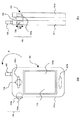
図1は本発明の携帯端末装置の一例である携帯電話機の閉状態を示す図で、(a)は正面図、(b)は左側面図である。図2は本発明の携帯端末装置の一例である携帯電話機の開状態を示す図で、(a)は正面図、(b)は背面図である。図3は本発明の携帯端末装置の一例である携帯電話機の開状態を示す図で、(a)は左側面図、(b)は右側面図である。
【0008】
図1及び図2に示すように、この携帯電話機100は、表示部106を有する表示部側筐体101aと、主操作部102を有する操作部側筐体101bとから構成され、両筐体101a,101bは重ねて配置され、表示部側筐体101aが操作部側筐体101bの主操作部102を覆うようになっている。
両筐体101a,101bは、重ねた状態(「閉状態」ともいう)において、両筐体101a,101bの端部に備える軸104により連結されており、重ねた状態においても表示部106の表示面106aを外側から見ることができるように、表示部側筐体101aの操作部側筐体101bと反対側の面に表示部106を備えるとともに、重ねた状態でも各種アプリケーションを起動させることができるように、表示部側筐体101a及び操作部側筐体101bの側面には補助的操作部103を設けてある。
【0009】
なお、107a,107bはそれぞれ表示部側筐体101aの表示部106を有する面に設けられたスピーカーで、表示部106を挟んで上下に配置されており、また、108は操作部側筐体101bの主操作部102を有する面に設けられたマイク、105は操作部側筐体101bの端面に設けられたアンテナである。
そして、表示部側筐体101aと操作部側筐体101bとが重ねられた状態から軸104を中心にして、表示部側筐体101aを矢印Aに示す方向に180度回動させることにより、図2及び図3に示すように、操作部側筐体101bに備える主操作部102が完全に外側に見える、開状態とすることができ、この時、表示部106は主操作部102と同じ方向を向いた状態で回動するため、開状態でも表示部106の表示面106aを外側から見ることができるようになっている。
【0010】
ただし、閉状態から表示部側筐体101aを操作部側筐体101bに対して180度回動させた開状態とすると、表示画面の上下の向きが逆になるので、このようなときには表示画面の上下が180度反転して表示されるようになっている。
また、この携帯電話機100は、開状態において表示部側筐体101aを操作部側筐体101bに対して傾斜させた状態で配置するようになっており、例えば、表示部側筐体101aの表示部106を有する面と反対側の面を操作部側筐体101bの主操作部102を有する面に対して0度より大きく、70度以下の角度範囲θで傾斜させることで、例えば、通話時に表示部側筐体101aのスピーカー107bをユーザーの耳元に近づければ、操作部側筐体101bのマイク108をユーザーの口元に近づけることができるようになっている。
【0011】
なお、この携帯電話機100では、表示部側筐体101aが軸104を中心にして回動するような構成を示したが、これとは別の実施形態として、レール等を設けて図1に示した状態から表示部側筐体101aを操作部側筐体101bに対して上方にスライドさせる構造や、表示部側筐体101aと操作部側筐体101bとがボールジョイント等の連結部を介して連結され、折り畳み動作と捻り動作を共に行うことができる構造としたものであっても良く、このように少なくとも表示部を有する表示部側筐体と、少なくとも主操作部を有する操作部側筐体とが開閉可能に連結され、主操作部が閉状態にて前記表示部側筐体により覆われ且つ開状態にて外側に露出するとともに、表示部の表示面が閉状態及び開状態のいずれの状態でも外側に露出させることが可能な構造を有するものであれば構わない。
【0012】
次に、主操作部102及び補助的操作部103について説明する。
主操作部102は、図2(a)に示すように、文字や数字の入力を行うテンキー102c、表示面106aに表示されている項目の選択、決定や表示面106aのスクロール等を行う十字キー102a、及び各種設定項目を呼び出したり、発呼や終話、あるいは電源のON/OFF等を行うファンクションキー102b等からなる。
補助的操作部103は、図1(b)に示すように、表示部側筐体101aの側面に有するサイドキー103bと、操作部側筐体101bの側面に有する3方向レバー103aとからなり、サイドキー103bは、携帯電話機100が閉状態であって表示部106の表示面106aが待ち受け画面である場合、その押下により携帯電話機100が備えるアプリケーションの一つである電話帳を起動させ、
【0013】
図5(b)に示すような電話帳画面202を表示部106に表示させることができ、また、携帯電話機100が閉状態であってアプリケーションが起動し、表示部106の表示面106aに前記アプリケーションが表示されている場合、その押下により一つ前の表示画面に戻すことができるようになっている。
また、3方向レバー103aは、矢印Bに示すように上下に移動させることにより表示面106aに表示されている項目の選択や表示面106aのスクロール等を行うことができ、また、押下することで決定ボタンとして機能するようになっている。
【0014】
そして、図1に示すように、表示部側筐体101aと操作部側筐体101bとが重ねられた閉状態では、主操作部102による操作ができないため、補助的操作部103の操作によって、各種アプリケーションを起動させることができるとともに、着信があった場合、通話することができるようにもなっている。
即ち、閉状態にて携帯電話機100に着信があった場合、2つのスピーカー107a,107bより独立した着信音が放音され、補助的操作部103の3方向レバー103aを押下すると着信音が止まり、スピーカー107bが不動作となるとともに、スピーカー107aが受話スピーカーとなり、またマイク108が動作して通話を行うことができるようになっている。
【0015】
また、図2に示すように、表示部側筐体101aと操作部側筐体101bとが開いた状態では、主操作部102によって、各種アプリケーションを起動させることができるとともに、着信があった場合、通話することができるようになっている。
即ち、開状態にて携帯電話機100に着信があった場合、2つのスピーカー107a,107bより独立した着信音が放音され、主操作部102のファンクションキー102bを押下すると着信音が止まり、スピーカー107aが不動作となるとともに、スピーカー107bが受話スピーカーとなり、またマイク108が動作して通話を行うことができるようになっている。なお、開状態の時、誤動作を防止するために、3方向レバー103a及びサイドキー103bの操作は無効とするようになっている。
【0016】
次に、本発明の携帯電話機100における回路ブロック図について説明する。
制御部23には、主操作部102、補助的操作部103、マイク108、スピーカー107a,107b、表示部106、メモリ26、アンテナ105に接続された無線部21、両筐体101a,101bの開閉状態を検出する開閉検出部25がそれぞれ接続されており、符号22に示す各種アプリケーションは制御部23の下で動作するようになっている。
【0017】
制御部23は、両筐体101a,101bが閉状態であって、表示部106の表示部106aに、図5(a)に示すような待ち受け画面201が表示されている状態において、サイドキー103bが押下されると携帯電話機100のアプリケーションの一つである電話帳を起動させ、表示部106の表示面106aに、図5(b)に示すような電話帳画面202を表示するよう制御するようになっている。
【0018】
そして、表示部106aに電話帳画面202が表示された状態で、3方向レバー103aを矢印Bのように上下動させることにより、電話帳画面202に表示されている発信先を選択することができるようになっており、特定の発信先を選択した状態で3方向レバー103aを押下すると、選択した発信先に発呼すると共に、表示部106の表示面106aを電話帳画面202から図5(c)に示す電話の発信画面203へ切り換えるようになっている。
【0019】
なお、本発明において、発信先を選択するとは、図5(b)に示すように、電話帳画面202に登録されている特定の発信先名の周囲の色を反転させている場合は勿論のこと、発信先の電話番号が表示されている場合であって、特定の発信先の電話番号の周囲の色を反転させている場合など、発呼すべき相手先を選択した状態のことをいう。
【0020】
また、制御部23は、両筐体101a,101bが開状態であって、前述のように、電話帳画面202より、3方向レバー103aの操作によって特定の発信先を選択した状態で、両筐体101a,101bの開動作が行われ、開閉検出部25で開状態を検出すると、前記選択した特定の発信先へ自動的に発信すると共に、表示部106の表示面106aを電話帳画面202から図5(c)に示す電話の発信画面203へ切り換えるよう制御するようになっている。
【0021】
さらに、制御部23は、発信先との通話が確立された通話状態の間であって、両筐体101a,101bを開状態から閉状態とすると、開閉検出部25からの信号に基づき、通話を保留状態として通話回線を維持したまま表示部106の表示面106aを、図5(e)に示すメニュー画面205に切り換え、携帯電話機100が備える各種アプリケーションを起動、操作することができるようになっている。即ち、3方向レバー103aを上下動させてメニュー画面205から特定のアプリケーションを選択し、次いで3方向レバー103aを押下することで選択したアプリケーションを起動させ、そのアプリケーションに対応する画面を表示部106に表示させ、通話中でもアプリケーション中の情報を閲覧することができるようになっている。
そして、アプリケーションの起動中又は終了後に、前記両筐体101a,101bを再度開状態とすれば、開閉検出部25からの信号に基づき、保留状態を解除して電話を継続することができると共に、表示部106の表示面106aを、図5(d)に示すような通話中の表示画面204に切り換えるようになっている。
【0022】
次に、本発明の携帯電話機100の動作について図6乃至図8を基に説明する。
図6に示すように、携帯電話機100の閉状態において、3方向レバー103aを押下して(S501)表示面106aにメニュー画面205を表示させる(S502)。メニュー画面205から電話帳機能が選択された場合、電話帳を起動させて表示部106に電話帳画面202を表示させる(S503)。そして、ユーザーが電話帳の登録データの中から発信先を一つ選択し(S505)、次いで携帯電話機100を閉状態から開状態とすると(S507)、選択した発信先へ自動的に発呼すると共に(S511)、表示部106の表示画面を180°反転させ(S509)、さらに表示画面に電話の発信画面203を表示する(S513)。そして、発信先との通話確立ができた場合には(S515)、表示部106に通話中の表示画面204を表示し、また、発信先との通話確立ができなかった場合には(S515)、通話確立をしようとしていた呼を切断し(S519)、表示部106に待ち受け画面201を表示する(S521)。
【0023】
このように、本発明によれば、電話帳の中から発信先を選択したあと、電話をかけるのに有効な開状態とするための開動作と合わせて発呼動作を同時に行うことができるため、電話をかける際の手間を省くことができる。
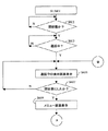
次に、図7に示すように、携帯電話機100が開状態であって(S601)、通話中である場合には(S603)、表示部106に通話中の表示画面204を表示し、この状態で開状態から閉状態とすると(S607)、通話を保留状態とし、表示部106にメニュー画面205を表示する(S609)。
【0024】
次いで、S609に続く処理を図8を基に説明する。
メニュー画面205のメニュー項目の中から起動させたいアプリケーションを選択する。
例えば、電話帳に登録してある通話相手以外の人の電話番号やメールアドレス等を確認したい場合、3方向レバー103aの操作によって電話帳機能を選択し(S701)、3方向レバー103aを押下すると(S709)、表示部106に電話帳画面202を表示する(S717)。
メモ帳に書き込んである情報を閲覧したい場合、3方向レバー103aの操作によってメモ帳機能を選択し(S703)、3方向レバー103aを押下すると(S711)、表示部106に不図示のメモ帳画面を表示する(S719)。
スケジュール帳に書き込んである情報を閲覧したい場合、3方向レバー103aの操作によってスケジュール帳機能を選択し(S705)、3方向レバー103aを押下すると(S713)、表示部106に不図示のスケジュール帳画面を表示する(S721)。
メールの履歴を閲覧したい場合、3方向レバー103aの操作によってメール機能を選択し(S707)、3方向レバー103aを押下すると(S715)、表示部106に不図示のメール履歴画面を表示する(S723)。
【0025】
このように、本発明によれば、通話中に携帯電話機100に備える各種アプリケーション中の情報を確認したくなった場合、開状態から閉状態とすることで通話を保留状態とし、回線をわざわざ切断することなく各種アプリケーション中の情報を確認することができる。
そして、閉状態でアプリケーション中における情報の確認が完了し、アプリケーションの起動中又は終了後に携帯電話機100を再度開状態とすると(S725)、表示部106を通話中の表示画面204に切り換えると共に、通話の保留状態を解除し、通話を続けることができる。
【0026】
以上、本実施形態では携帯電話機を例にとって説明したが、この他、PDAなど電話機能を備えた携帯端末装置にも本発明を適用できることは言う迄もない。
また、本発明は上述した実施形態だけに限定されるものではなく、本発明の要旨を逸脱しない範囲で改良や変更したものにも適用できることは言う迄もない。
【0027】
【発明の効果】
以上のように、本発明の携帯端末装置によれば、手間をかけずに発呼動作を行うことができると共に、通話中に携帯端末装置が備える各種アプリケーション中における情報を確認することができ、従来のようにわざわざ電話を切って確認する必要がない。
【図面の簡単な説明】
【図1】本発明の携帯端末装置の一例である携帯電話機の閉じた状態を示す図で、(a)は正面図、(b)は左側面図。
【図2】本発明の携帯端末装置の一例である携帯電話機の開いた状態を示す図で、(a)は正面図、(b)は背面図。
【図3】本発明の携帯端末装置の一例である携帯電話機の開いた状態を示す図で、(a)は左側面図、(b)は右側面図。
【図4】本発明の携帯端末装置の一例である携帯電話機の回路ブロック図。
【図5】本発明の携帯端末装置の一例である携帯電話機における各種アプリケーションの画面であり、(a)は待ち受け画面、(b)は電話帳画面、(c)は電話の発信画面、(d)は通話中の表示画面、(e)はメニュー画面。
【図6】本発明の携帯端末装置の一例である携帯電話機の動作を説明するためのフローチャート。
【図7】本発明の携帯端末装置の一例である携帯電話機の動作を説明するためのフローチャート。
【図8】本発明の携帯端末装置の一例である携帯電話機の動作を説明するためのフローチャート。
【符号の説明】
21 無線部
22 各種アプリケーション部
23 制御部
25 開閉検出部
26 メモリ
100 携帯電話機
101a 表示部側筐体
101b 操作部側筐体
103 補助的操作部
103a 3方向レバー
103b サイドキー
104 軸
105 アンテナ
106 表示部
106a 表示面
107a,107b スピーカー
108 マイク[0001]
TECHNICAL FIELD OF THE INVENTION
The present invention relates to a mobile terminal device such as a mobile phone and a PDA (Personal Digital Assistants) having a plurality of housings connected to each other in a superimposable manner and having a call function together with a plurality of applications.
[0002]
[Prior art]
Patent Literature 1 discloses a folding type mobile phone having a sub-display unit, in which a destination is displayed on the sub-display unit and a call is made when the mobile phone is opened from the folded state.
[0003]
[Patent Document 1]
JP 2002-199463 A
[Problems to be solved by the invention]
However, in this type of foldable mobile phone, the sub-display has a smaller display area than the main display, so that there is a problem that the convenience is poor when the same person has a plurality of contacts. Was.
Also, even if there is information that you want to check in the application on the mobile phone during a call, you can not browse it, you must hang up once, browse the information you want to check, and make a call again There was also an inconvenience.
In addition, such a problem is not limited to a mobile phone, but also applies to a mobile terminal device such as a PDA (Personal Digital Assistants) having a call function.
[0005]
[Object of the invention]
SUMMARY OF THE INVENTION An object of the present invention is to provide a portable terminal device capable of performing a calling operation without any trouble and confirming information in various applications provided in the portable terminal device during a call. .
[0006]
[Means for Solving the Problems]
In view of the above problem, an invention according to claim 1 is configured such that at least a display unit side housing having a display unit and at least an operation unit side housing having a main operation unit are connected to be openable and closable, and the main operation unit Can be covered by the display unit side housing in the closed state and exposed to the outside in the open state, and the display surface of the display unit can be exposed to the outside in both the closed state and the open state. In the portable terminal device having at least one auxiliary operation unit on a surface other than the surfaces of the two housings facing each other in the closed state, the telephone directory is operated by operating the auxiliary operation unit in the closed state. After starting up, when the two housings are opened in a state where a call destination is selected from the telephone directory, a means for calling the selected call destination, and When both housings are closed, the call state is maintained. And means for activating an application by operating the auxiliary operation unit, and means for maintaining the call state when the two housings are opened again during or after the application is activated. It is characterized by.
According to a second aspect of the present invention, in the portable terminal device according to the first aspect, when the two housings are opened again during or after the application is started, the display screen of the display unit is in a call state. It has a means for switching to a display screen.
The invention according to claim 3 is the portable terminal device according to
The application may be any one of a phone book, a memo book, a schedule book, and a mail history.
[0007]
BEST MODE FOR CARRYING OUT THE INVENTION
Hereinafter, embodiments of the present invention will be described.
1A and 1B are diagrams showing a closed state of a mobile phone as an example of the mobile terminal device of the present invention, wherein FIG. 1A is a front view and FIG. 1B is a left side view. 2A and 2B are views showing an open state of a mobile phone as an example of the mobile terminal device of the present invention, wherein FIG. 2A is a front view and FIG. 2B is a rear view. 3A and 3B are diagrams showing an open state of a mobile phone as an example of the mobile terminal device of the present invention, wherein FIG. 3A is a left side view, and FIG. 3B is a right side view.
[0008]
As shown in FIGS. 1 and 2, the
The two
[0009]
Then, by rotating the display unit-
[0010]
However, if the display
The
[0011]
In this
[0012]
Next, the
The
As shown in FIG. 1B, the
[0013]
A
By moving the three-
[0014]
Then, as shown in FIG. 1, in the closed state where the display
That is, when an incoming call arrives at the
[0015]
Further, as shown in FIG. 2, when the display
That is, when there is an incoming call to the
[0016]
Next, a circuit block diagram of the
The
[0017]
The
[0018]
Then, by moving the three-
[0019]
In the present invention, the selection of the destination is of course not only when the color around the specific destination name registered in the
[0020]
Further, the
[0021]
Further, when the two
Then, if the two
[0022]
Next, the operation of the
As shown in FIG. 6, in the closed state of the
[0023]
As described above, according to the present invention, after a destination is selected from the telephone directory, a calling operation can be performed simultaneously with an opening operation for setting an effective open state for making a call. This saves time when making a call.
Next, as shown in FIG. 7, when the
[0024]
Next, processing subsequent to S609 will be described with reference to FIG.
An application to be started is selected from menu items on the
For example, when the user wants to confirm the telephone number or mail address of a person other than the call partner registered in the telephone directory, the user selects the telephone directory function by operating the three-
When the user wants to view the information written in the memo pad, the memo pad function is selected by operating the three-
When the user wants to view the information written in the schedule book, the user selects the schedule book function by operating the three-
When the user wants to view the mail history, the mail function is selected by operating the three-
[0025]
As described above, according to the present invention, when it is desired to check information in various applications provided in the
When the confirmation of the information in the application in the closed state is completed, and the
[0026]
As described above, the present embodiment has been described by taking the mobile phone as an example. However, it goes without saying that the present invention can be applied to a mobile terminal device having a telephone function such as a PDA.
Further, it is needless to say that the present invention is not limited to the above-described embodiment, but can be applied to an improved or changed one without departing from the gist of the present invention.
[0027]
【The invention's effect】
As described above, according to the portable terminal device of the present invention, it is possible to perform a calling operation without any trouble, and to confirm information in various applications provided in the portable terminal device during a call, There is no need to hang up and confirm the call as in the past.
[Brief description of the drawings]
FIG. 1 is a diagram showing a closed state of a mobile phone as an example of the mobile terminal device of the present invention, wherein (a) is a front view and (b) is a left side view.
FIGS. 2A and 2B are views showing an open state of a mobile phone as an example of the mobile terminal device of the present invention, wherein FIG. 2A is a front view and FIG.
FIGS. 3A and 3B are views showing an open state of a mobile phone as an example of the mobile terminal device of the present invention, wherein FIG. 3A is a left side view, and FIG.
FIG. 4 is a circuit block diagram of a mobile phone as an example of the mobile terminal device of the present invention.
5A and 5B are screens of various applications on a mobile phone as an example of the mobile terminal device of the present invention, wherein FIG. 5A is a standby screen, FIG. 5B is a telephone directory screen, FIG. ) Is a display screen during a call, and (e) is a menu screen.
FIG. 6 is a flowchart for explaining the operation of a mobile phone as an example of the mobile terminal device of the present invention.
FIG. 7 is a flowchart for explaining the operation of a mobile phone as an example of the mobile terminal device of the present invention.
FIG. 8 is a flowchart for explaining the operation of a mobile phone as an example of the mobile terminal device of the present invention.
[Explanation of symbols]
21
Claims (3)
前記主操作部は閉状態にて前記表示部側筐体により覆われ且つ開状態にて外側に露出すると共に、前記表示部の表示面は閉状態及び開状態のいずれの状態でも外側に露出させることが可能であって、
前記閉状態にて前記両筐体の互いに対向する面以外の面に少なくとも一つの補助的操作部を備える携帯端末装置において、
前記閉状態にて前記補助的操作部の操作により電話帳を起動させたあと、当該電話帳から発信先を選択した状態で前記両筐体を開いた状態としたとき、前記選択した発信先に発呼する手段と、
前記発信先との通話中に前記両筐体を閉じたとき、通話状態を維持すると共に、前記補助的操作部の操作によりアプリケーションを起動させる手段と、
前記アプリケーションの起動中又は終了後に前記両筐体を再度開いた状態としたとき、前記通話状態を維持する手段とを有することを特徴とする携帯端末装置。A display unit side housing having at least a display unit and an operation unit side housing having at least a main operation unit are connected to be openable and closable,
The main operation unit is covered by the display unit side housing in the closed state and is exposed to the outside in the open state, and the display surface of the display unit is exposed to the outside in both the closed state and the open state. Is possible,
In the portable terminal device having at least one auxiliary operation unit on a surface other than the surfaces facing each other of the two housings in the closed state,
After activating the telephone directory by operating the auxiliary operation unit in the closed state, when the two housings are opened with the destination selected from the telephone directory, the selected destination is Means for calling;
Means for activating an application by operating the auxiliary operation unit while maintaining the call state when the two housings are closed during a call with the call destination;
Means for maintaining the call state when the two housings are reopened during or after the application is activated.
Priority Applications (1)
| Application Number | Priority Date | Filing Date | Title |
|---|---|---|---|
| JP2003050004A JP3883515B2 (en) | 2003-02-26 | 2003-02-26 | Mobile terminal device |
Applications Claiming Priority (1)
| Application Number | Priority Date | Filing Date | Title |
|---|---|---|---|
| JP2003050004A JP3883515B2 (en) | 2003-02-26 | 2003-02-26 | Mobile terminal device |
Publications (2)
| Publication Number | Publication Date |
|---|---|
| JP2004260617A true JP2004260617A (en) | 2004-09-16 |
| JP3883515B2 JP3883515B2 (en) | 2007-02-21 |
Family
ID=33115561
Family Applications (1)
| Application Number | Title | Priority Date | Filing Date |
|---|---|---|---|
| JP2003050004A Expired - Fee Related JP3883515B2 (en) | 2003-02-26 | 2003-02-26 | Mobile terminal device |
Country Status (1)
| Country | Link |
|---|---|
| JP (1) | JP3883515B2 (en) |
Cited By (4)
| Publication number | Priority date | Publication date | Assignee | Title |
|---|---|---|---|---|
| JP2008160482A (en) * | 2006-12-22 | 2008-07-10 | Sharp Corp | COMMUNICATION TERMINAL DEVICE, CALLING METHOD, PROGRAM, AND RECORDING MEDIUM |
| JP2008289081A (en) * | 2007-05-21 | 2008-11-27 | Sharp Corp | Portable information terminal |
| US8326368B2 (en) | 2007-12-28 | 2012-12-04 | Kyocera Corporation | Mobile communication terminal |
| JP2013158035A (en) * | 2013-04-01 | 2013-08-15 | Kyocera Corp | Portable communication terminal |
-
2003
- 2003-02-26 JP JP2003050004A patent/JP3883515B2/en not_active Expired - Fee Related
Cited By (5)
| Publication number | Priority date | Publication date | Assignee | Title |
|---|---|---|---|---|
| JP2008160482A (en) * | 2006-12-22 | 2008-07-10 | Sharp Corp | COMMUNICATION TERMINAL DEVICE, CALLING METHOD, PROGRAM, AND RECORDING MEDIUM |
| JP2008289081A (en) * | 2007-05-21 | 2008-11-27 | Sharp Corp | Portable information terminal |
| US8326368B2 (en) | 2007-12-28 | 2012-12-04 | Kyocera Corporation | Mobile communication terminal |
| US8538489B2 (en) | 2007-12-28 | 2013-09-17 | Kyocera Corporation | Mobile communication terminal |
| JP2013158035A (en) * | 2013-04-01 | 2013-08-15 | Kyocera Corp | Portable communication terminal |
Also Published As
| Publication number | Publication date |
|---|---|
| JP3883515B2 (en) | 2007-02-21 |
Similar Documents
| Publication | Publication Date | Title |
|---|---|---|
| JP4073296B2 (en) | Stackable mobile phone | |
| JP3949048B2 (en) | Stackable mobile terminal device | |
| JP3906655B2 (en) | Mobile phone | |
| JP2004336091A (en) | Foldable mobile communication apparatus | |
| JP3961397B2 (en) | Mobile terminal device | |
| CN100559815C (en) | Portable terminal with display unit and display method thereof | |
| JP5206670B2 (en) | Portable terminal device, function activation method and program thereof | |
| JPH1093668A (en) | Portable radio equipment | |
| JP3957693B2 (en) | Multi-window display type portable terminal device | |
| JP2834078B2 (en) | Mobile phone with flip mechanism | |
| JP2001339497A (en) | Mobile terminal housing structure | |
| JP2004260617A (en) | Mobile terminal device | |
| JP4087610B2 (en) | Portable communication device | |
| JP3886409B2 (en) | Mobile phone | |
| JP4019750B2 (en) | Foldable portable information terminal, response hold method used therefor, and program thereof | |
| JP4081738B2 (en) | Mobile phone | |
| JP2003333139A (en) | Foldable portable information terminal | |
| US7590431B2 (en) | System and method for outputting dual voice of mobile terminal | |
| JP2005159965A (en) | Mobile communication terminal device | |
| JP2004312631A (en) | Foldable portable telephone set | |
| JP3949561B2 (en) | Mobile terminal device | |
| JP3680777B2 (en) | Mobile phone | |
| JP4502583B2 (en) | Mobile terminal device | |
| JP4351714B2 (en) | Stackable mobile phone | |
| JP4152244B2 (en) | Communication device |
Legal Events
| Date | Code | Title | Description |
|---|---|---|---|
| A621 | Written request for application examination |
Free format text: JAPANESE INTERMEDIATE CODE: A621 Effective date: 20050125 |
|
| TRDD | Decision of grant or rejection written | ||
| A01 | Written decision to grant a patent or to grant a registration (utility model) |
Free format text: JAPANESE INTERMEDIATE CODE: A01 Effective date: 20061113 |
|
| A61 | First payment of annual fees (during grant procedure) |
Free format text: JAPANESE INTERMEDIATE CODE: A61 Effective date: 20061114 |
|
| R150 | Certificate of patent or registration of utility model |
Free format text: JAPANESE INTERMEDIATE CODE: R150 |
|
| FPAY | Renewal fee payment (event date is renewal date of database) |
Free format text: PAYMENT UNTIL: 20091124 Year of fee payment: 3 |
|
| FPAY | Renewal fee payment (event date is renewal date of database) |
Free format text: PAYMENT UNTIL: 20101124 Year of fee payment: 4 |
|
| FPAY | Renewal fee payment (event date is renewal date of database) |
Free format text: PAYMENT UNTIL: 20101124 Year of fee payment: 4 |
|
| FPAY | Renewal fee payment (event date is renewal date of database) |
Free format text: PAYMENT UNTIL: 20111124 Year of fee payment: 5 |
|
| FPAY | Renewal fee payment (event date is renewal date of database) |
Free format text: PAYMENT UNTIL: 20111124 Year of fee payment: 5 |
|
| FPAY | Renewal fee payment (event date is renewal date of database) |
Free format text: PAYMENT UNTIL: 20121124 Year of fee payment: 6 |
|
| FPAY | Renewal fee payment (event date is renewal date of database) |
Free format text: PAYMENT UNTIL: 20121124 Year of fee payment: 6 |
|
| FPAY | Renewal fee payment (event date is renewal date of database) |
Free format text: PAYMENT UNTIL: 20131124 Year of fee payment: 7 |
|
| LAPS | Cancellation because of no payment of annual fees |