JP2004222771A - Ultrasonic probe and ultrasonic diagnostic apparatus using the probe - Google Patents
Ultrasonic probe and ultrasonic diagnostic apparatus using the probe Download PDFInfo
- Publication number
- JP2004222771A JP2004222771A JP2003010716A JP2003010716A JP2004222771A JP 2004222771 A JP2004222771 A JP 2004222771A JP 2003010716 A JP2003010716 A JP 2003010716A JP 2003010716 A JP2003010716 A JP 2003010716A JP 2004222771 A JP2004222771 A JP 2004222771A
- Authority
- JP
- Japan
- Prior art keywords
- ultrasonic
- position information
- phase
- drive motor
- signal
- Prior art date
- Legal status (The legal status is an assumption and is not a legal conclusion. Google has not performed a legal analysis and makes no representation as to the accuracy of the status listed.)
- Pending
Links
Images


Landscapes
- Ultra Sonic Daignosis Equipment (AREA)
Abstract
【課題】超音波振動子の画像位置情報とモータの回転位置情報と連動した診断装置を提供することを目的とする。
【解決手段】超音波プローブの先端39に超音波振動子1、2を駆動する駆動モータ3を構成し、その駆動モータ3に直接、超音波振動子1、2を取り付ける。駆動モータ3の位置情報検出器を超音波振動子1、2の位置情報検出器として使用し、超音波振動子1、2の画像位置情報とモータの回転位置情報と連動する。
【選択図】 図1An object of the present invention is to provide a diagnostic device that is linked with image position information of an ultrasonic transducer and rotational position information of a motor.
A driving motor for driving the ultrasonic transducers is provided at a distal end of an ultrasonic probe, and the ultrasonic transducers are attached directly to the driving motor. The position information detector of the drive motor 3 is used as the position information detector of the ultrasonic vibrators 1 and 2, and is linked with the image position information of the ultrasonic vibrators 1 and 2 and the rotational position information of the motor.
[Selection diagram] Fig. 1
Description
【0001】
【発明の属する技術分野】
本発明は、超音波プローブとそれを使用した超音波診断装置に関するものである。
【0002】
【従来の技術】
例えば、医療用超音波プローブは、超音波振動子を設けた先端部を被診断者の体内に挿入して診断対象の診断部付近に配置し、超音波振動子により超音波を照射し、診断部によって反射された反射波を超音波振動子により受信し、その受信された反射波のデータが診断装置に送信されてデータ処理されることにより、診断部の断面画像が得られることになっており、更に、超音波振動子を回転させることにより、診断部の複数の断面画像を得ることができるようになっている。
【0003】
従来、複数の超音波画像を得るための医療用超音波プローブとしては、経食道用超音波プローブが知られている(たとえば特許文献1を参照)。これは、基端部に設けられたダイアルを手動で回転操作することによりワイヤを介して超音波振動子を回転させる構成であり、超音波振動子の回転位置はダイアルの操作量で知ることができる。
【0004】
しかしながら、このような構成ではワイヤに伸び若しくは緩みが生じると、ダイアルの操作量に対する超音波振動子の回転量が変化するので、その回転位置を正確に知ることができない。しかも、手動のダイアル操作方式では、超音波振動子を一定間隔で回転、停止させることは難しく医療分野で要望の高い三次元撮影において画像がばらついてしまうという不具合がある。
【0005】
そこで、更に従来では、経膣超音波プローブで先端部モータを搭載するものが登場してきた(たとえば、特許文献2を参照)。これは超音波プローブの先端部に設けられたモータにより超音波振動子を回転させる構成であり、AB相の2相インクリメンタルエンコーダでロータの相対位置情報を検出し、Z相MRセンサーでロータの絶対位置情報を検出し、その2つの相対位置情報と絶対位置情報を用いて、絶対位置を基準位置として相対位置情報を割りふることでロータの回転角度情報を決定し、その回転角度情報をもとにモータコイルへの通電制御を行っている。
【0006】
【特許文献1】
特開平2−206450号公報(第5頁、図1、図3)
【特許文献2】
特開平7−128312号公報(第4頁、図1)
【0007】
【発明が解決しようとする課題】
しかしながら、上記従来例の超音波プローブでは位置検出用マグネットとMRセンサにより構成されたエンコーダによりモータ1回転に対しA、B2相の均等な数十パルスの信号が発生し、モータの位置検出を行っているが、近年要望されている、より高精度な画像を得るためには、モータの制御性能を上げる必要があるが、それ以上に超音波振動子の位置を正確に把握し、その超音波振動子の位置情報の分解能を上げる必要がある。
【0008】
まずモータの制御性能を上げるために、より高精度なモータの位置検出を行う必要がある。それには従来の超音波プローブの構成では検出用マグネットの着磁により形成されている磁極の間隔を狭くするか、あるいは従来と同一の磁極の間隔で検出用マグネットの外径を大きくする必要がある。かかるに、磁極の間隔を狭くした場合エンコーダの信号を得るためには位置検出用マグネット外径部とMRセンサの距離をより小さくする必要があり、距離を小さくすることにより位置検出用マグネットとMRセンサの位置調整がより難しくなると共に、温度等の影響により位置検出用マグネットの外径が変化した場合、MRセンサに接触し、MRセンサを破損してしまう場合が発生する。また、位置検出用マグネットの外径を大きくすると超音波プローブの先端が大きくなってしまうという問題があった。
【0009】
また、超音波振動子の位置を正確に把握し、駆動モータと間接的に取り付ける方法では、部品のばらつきや経年変化や環境変化に伴っての誤差が生じてしまうなど課題がある。
【0010】
さらに、超音波振動子の位置情報は駆動モータと間接的な取付であるので、位置情報手段は十分なものとはなり得ない。
【0011】
本発明は、このような従来の問題を解決するものであり、より高精度なモータ及び超音波振動子の位置検出を容易に行う超音波プローブを提供すると共に、前記超音波プローブを用いることにより、より高精度な画像を得られる超音波診断装置を提供することを目的とする。
【0012】
【課題を解決するための手段】
本発明は、上記目的を達成するために、超音波プローブの先端に超音波振動子を駆動する駆動モータを構成し、その駆動モータに直接、超音波振動子を取り付けることで、部品のばらつきや経年変化や環境変化に伴っての位置情報誤差をなくす。
【0013】
さらに、駆動モータの回転制御情報を超音波振動子の角度情報として使用可能なように、超音波振動子の位置を確定する。
下記のいずれかでもって、ロータに対する超音波振動子の取付位置を絶対位置として確定することが可能となる。
(1)ロータのZ相基準情報位置に合わせて、超音波振動子を取り付ける。
(2)または、超音波振動子の取付位置を基準にしてロータのZ相基準情報
を合わせる。
【0014】
さらに、超音波振動子の位置情報分解能を上げるためには、位置情報の検出器の性能を上げる必要がある。超音波振動子を駆動するモータをも超音波プローブの先端に構成している関係で、検出器を設けるスペースがないので、駆動モータの位置情報検出器を超音波振動子の位置情報検出器として使用する。したがって、超音波振動子の位置情報分解能を上げることは駆動モータの位置情報分解能を上げることである。超音波振動子の駆動モータの相対位置情報手段としてのエンコーダのパルス数を上げる。
【0015】
さらに、超音波振動子の位置情報とロータの相対位置情報との関連は超音波振動子の絶対位置はZ相基準情報位置と関連をもたせることで、Z相基準情報位置とロータの相対位置情報と関連づけることで可能となる。Z相の位置とAB相の信号の確定するために下記のいずれかの規定をなす。
(1)信号の立ち上がりとA相(またはB相)信号の立ち上がりの位相差を規定する。
(2)または、決められたZ相信号の信号幅のなかにA相(またはB相)信号の立ち上がりを調整する。
【0016】
さらに、超音波振動子の画像位置情報とモータの回転位置情報と連動することで、駆動モータが回転変動しても超音波振動子の画像情報を正確な角度情報として使用でき、画質及び精度の良い超音波画像が得られる。
【0017】
さらに、超音波振動子の位置情報を超音波診断装置に伝達するためには、下記のような手段をとることで、課題が解決できる。
(1)AB相の信号とZ相信号を波形処理して、矩形波信号として、超音波診断装置本体へ伝達する。この場合は超音波振動子の位置は本体側で処理し、把握して管理されている。
(2)AB相の信号の波形情報を矩形波処理して、超音波診断装置本体へ伝達する。この場合は超音波振動子の位置は本体側で処理し、把握して管理されている。超音波振動子の絶対位置は超音波振動子を取り付けた時の情報をもとに把握する。
(3)AB相の信号とZ相信号を波形処理して、プローブ側のマイコンで情報処理し、位置情報をビット情報量に変換してシリアル通信手段等でプローブ側と本体側とを送受信して、情報伝達を行う。
(4)AB相の信号を波形処理して、プローブ側のマイコンで情報処理し、さらに、超音波振動子を取り付けた時の情報をもとに超音波振動子の絶対位置を把握し、プローブ側のマイコンで情報処理管理し、位置情報をビット情報量に変換してシリアル通信手段等でプローブ側と本体側とを送受信して、情報伝達を行う。
【0018】
【発明の実施の形態】
本発明の請求項1に記載の発明は超音波透過性を有する窓材からなるウインドウケースを具備し、超音波振動子と前記超音波振動子を駆動させる駆動モータとを超音波伝播媒質でウインドウケース内に内包した超音波プローブにおいて、超音波振動子を駆動モータのロータフレームの外周部に取り付けて、駆動モータの駆動軸を中心に超音波振動子を回転させ、回転に伴って超音波振動子の超音波ビーム軌跡面を形成し、回転側の超音波振動子の信号伝達手段を具備し、前記駆動モータと超音波振動子とは同一回転中心で同じ回転数を有し、90度位相差のある2相の信号を発生させるエンコーダと、前記エンコーダの2相の出力信号を増幅する増幅回路と増幅後を矩形波処理する整形処理回路を具備し、前記整形処理回路からの2相の出力信号を駆動モータの位置情報とし、またその矩形位置情報を超音波診断装置本体にも伝達し、超音波振動子の画像位置情報とモータの回転位置情報と連動したことを特徴とする超音波プローブとしたものであり、超音波プローブの先端に超音波振動子を駆動する駆動モータを構成し、その駆動モータに直接、超音波振動子を取り付けることで、部品のばらつきや経年変化や環境変化に伴っての位置情報誤差をなくすることができ、駆動モータの位置情報検出器を超音波振動子の位置情報検出器として使用し、超音波振動子を駆動するモータを超音波プローブの先端に構成した小型な超音波プローブができる。さらに駆動モータの駆動軸と超音波振動子の回転軸が同一軸であり、駆動モータの位置情報が超音波振動子の位置情報に採用できるので、超音波振動子の画像位置情報とモータの回転位置情報と連動することで、駆動モータが回転変動しても超音波振動子の画像情報を正確な角度情報として使用でき、画質及び精度の良い超音波画像が得られる。また、AB相の信号の波形情報を矩形波処理して、超音波診断装置本体へ伝達することで、超音波振動子の画像位置情報とモータの回転位置情報と連動することができる。
【0019】
本発明の請求項2に記載の発明は90度位相差のある2相の信号を発生させるエンコーダと、前記エンコーダの2相の出力信号を増幅せずに矩形波処理する整形処理回路を具備し、前記整形処理回路からの2相の出力信号を駆動モータの位置情報とし、またその矩形位置情報を超音波診断装置本体にも伝達し、超音波振動子の画像位置情報とモータの回転位置情報と連動したことを特徴とする請求項1記載の超音波プローブとしたものであり、AB相の信号の波形情報を矩形波処理して、超音波診断装置本体へ伝達することで、超音波振動子の画像位置情報とモータの回転位置情報と連動することができるより小型の超音波プローブができる。
【0020】
本発明の請求項3に記載の発明は請求項1または請求項2記載の超音波プローブで得られた駆動モータ位置情報をビーム軌跡面の超音波断層画像の処理位置情報として使用処理する画像処理装置を有する超音波診断装置としたものであり、電子−機械走査式の2次元走査用超音波振動子駆動モータによって、超音波伝播媒質を内包しウインドウケース内に、駆動モータの駆動軸と超音波振動子の回転軸を同一軸で構成した超音波振動子駆動モータを構成させ、機構部を小型軽量にした超音波プローブができ、超音波振動子の画像位置情報とモータの回転位置情報と連動することで、駆動モータが回転変動しても超音波振動子の画像情報を正確な角度情報として使用でき、画質及び精度の良い超音波画像が得られる。さらに、超音波を走査するための駆動モータを小型、軽量に作製でき、駆動モータをウインドウケースに内蔵した超音波プローブを提供でき、そのプローブを用いて超音波診断ができ、診断の便宜性を向上させることができることで、より高精度な超音波断層画像が得られる超音波診断装置が提供できる。
【0021】
本発明の請求項4に記載の発明は超音波透過性を有する窓材からなるウインドウケースを具備し、超音波振動子と前記超音波振動子を駆動させる駆動モータとを超音波伝播媒質でウインドウケース内に内包した超音波プローブにおいて、超音波振動子を駆動モータのロータフレームの外周部に取り付けて、駆動モータの駆動軸を中心に超音波振動子を回転させ、回転に伴って超音波振動子の超音波ビーム軌跡面を形成し、回転側の超音波振動子の信号伝達手段を具備し、前記駆動モータと超音波振動子とは同一回転中心で同じ回転数を有し、モータの相対位置情報手段として90度位相差のある2相の信号を発生させるエンコーダと、基準位置情報手段としてロータフレーム外周のピンとMR素子とで構成する検出器と、相対位置情報手段のエンコーダの2相の出力信号及び基準位置情報手段の検出器の出力信号とを増幅する増幅回路と増幅後を矩形波処理する整形処理回路を具備し、前記整形処理回路からの2相の出力信号と1相の出力信号を駆動モータの位置情報とし、またその矩形位置情報を超音波診断装置本体にも伝達し、超音波振動子の画像位置情報とモータの回転位置情報と連動したことを特徴とする超音波プローブとしたものであり、超音波プローブの先端に超音波振動子を駆動する駆動モータを構成し、その駆動モータに直接、超音波振動子を取り付けることで、部品のばらつきや経年変化や環境変化に伴っての位置情報誤差をなくすることができ、駆動モータの位置情報検出器を超音波振動子の位置情報検出器として使用し、超音波振動子を駆動するモータを超音波プローブの先端に構成した小型な超音波プローブができる。さらに駆動モータの駆動軸と超音波振動子の回転軸が同一軸であり、駆動モータの位置情報が超音波振動子の位置情報に採用できるので、超音波振動子の画像位置情報とモータの回転位置情報と連動することで、駆動モータが回転変動しても超音波振動子の画像情報を正確な角度情報として使用でき、画質及び精度の良い超音波画像が得られる。また、AB相の信号とZ相信号を波形処理して、矩形波信号として、超音波診断装置本体へ伝達することで、超音波振動子の画像位置情報とモータの回転位置情報と連動することができる。
【0022】
本発明の請求項5に記載の発明は相対位置情報手段のエンコーダの2相の出力信号及び基準位置情報手段の検出器の出力信号とを増幅せずに矩形波処理する整形処理回路を具備し、前記整形処理回路からの2相の出力信号と1相の出力信号を駆動モータの位置情報とし、またその矩形位置情報を超音波診断装置本体にも伝達し、超音波振動子の画像位置情報とモータの回転位置情報と連動したことを特徴とする請求項4記載の超音波プローブとしたものであり、AB相、Z相の信号の波形情報を矩形波処理して、超音波診断装置本体へ伝達することで、超音波振動子の画像位置情報とモータの回転位置情報と連動することができる、より小型の超音波プローブができる。
【0023】
本発明の請求項6に記載の発明は請求項4または請求項5記載の超音波プローブで得られたビーム軌跡面の超音波断層画像の処理位置情報として使用処理する画像処理装置を有する超音波診断装置としたものであり、電子−機械走査式の2次元走査用超音波振動子駆動モータによって、超音波伝播媒質を内包しウインドウケース内に、駆動モータの駆動軸と超音波振動子の回転軸を同一軸で構成した超音波振動子駆動モータを構成させ、機構部を小型軽量にした超音波プローブができ、超音波振動子の画像位置情報とモータの回転位置情報と連動することで、駆動モータが回転変動しても超音波振動子の画像情報を正確な角度情報として使用でき、画質及び精度の良い超音波画像が得られる。さらに、超音波を走査するための駆動モータを小型、軽量に作製でき、駆動モータをウインドウケースに内蔵した超音波プローブを提供できる。そのプローブを用いて超音波診断ができ、診断の便宜性を向上させることができるので、より高精度な超音波断層画像が得られる超音波診断装置が提供できる。
【0024】
本発明の請求項7に記載の発明は超音波透過性を有する窓材からなるウインドウケースを具備し、超音波振動子と前記超音波振動子を駆動させる駆動モータとを超音波伝播媒質でウインドウケース内に内包した超音波プローブにおいて、超音波振動子を駆動モータのロータフレームの外周部に取り付けて、駆動モータの駆動軸を中心に超音波振動子を回転させ、回転に伴って超音波振動子の超音波ビーム軌跡面を形成し、回転側の超音波振動子の信号伝達手段を具備し、前記駆動モータと超音波振動子とは同一回転中心で同じ回転数を有し、90度位相差のある2相の信号を発生させるエンコーダと、前記エンコーダの2相の出力信号を波形処理した情報を駆動モータの位置情報とし、さらに同じ基準位置情報手段を基にした超音波振動子の位置情報として駆動モータの位置情報を本体装置側へビット通信情報に変換して送信する手段を具備し、超音波振動子の画像位置情報とモータの回転位置情報と連動したことを特徴とする超音波プローブとしたものであり、超音波プローブの先端に超音波振動子を駆動する駆動モータを構成し、その駆動モータに直接、超音波振動子を取り付けることで、部品のばらつきや経年変化や環境変化に伴っての位置情報誤差をなくすることができ、駆動モータの位置情報検出器を超音波振動子の位置情報検出器として使用し、超音波振動子を駆動するモータを超音波プローブの先端に構成した小型な超音波プローブができる。さらに駆動モータの駆動軸と超音波振動子の回転軸が同一軸であり、駆動モータの位置情報が超音波振動子の位置情報に採用できるので、超音波振動子の画像位置情報とモータの回転位置情報と連動することで、駆動モータが回転変動しても超音波振動子の画像情報を正確な角度情報として使用でき、画質及び精度の良い超音波画像が得られる。また、AB相の信号を波形処理して、プローブ側のマイコンで情報処理し、位置情報をビット情報量に変換にしてシリアル通信手段等でプローブ側と本体側とを送受信して、情報伝達を行うことで、超音波振動子の画像位置情報とモータの回転位置情報と連動することができる。
【0025】
本発明の請求項8に記載の発明は超音波透過性を有する窓材からなるウインドウケースを具備し、超音波振動子と前記超音波振動子を駆動させる駆動モータとを超音波伝播媒質でウインドウケース内に内包した超音波プローブにおいて、超音波振動子を駆動モータのロータフレームの外周部に取り付けて、駆動モータの駆動軸を中心に超音波振動子を回転させ、回転に伴って超音波振動子の超音波ビーム軌跡面を形成し、回転側の超音波振動子の信号伝達手段を具備し、前記駆動モータと超音波振動子とは同一回転中心で同じ回転数を有し、モータの相対位置情報手段として90度位相差のある2相の信号を発生させるエンコーダと、基準位置情報手段としてロータフレーム外周のピンとMR素子とで構成する検出器と、相対位置情報手段のエンコーダの2相の出力信号及び基準位置情報手段の検出器の出力信号とを波形処理した情報を駆動モータの位置情報とし、さらに同じ基準位置情報手段を基にした超音波振動子の位置情報として駆動モータの位置情報を本体装置側へビット通信情報に変換して送信する手段を具備し、超音波振動子の画像位置情報とモータの回転位置情報と連動したことを特徴とする超音波プローブとしたものであり、超音波プローブの先端に超音波振動子を駆動する駆動モータを構成し、その駆動モータに直接、超音波振動子を取り付けることで、部品のばらつきや経年変化や環境変化に伴っての位置情報誤差をなくすることができ、駆動モータの位置情報検出器を超音波振動子の位置情報検出器として使用し、超音波振動子を駆動するモータを超音波プローブの先端に構成した小型な超音波プローブができる。さらに駆動モータの駆動軸と超音波振動子の回転軸が同一軸であり、駆動モータの位置情報が超音波振動子の位置情報に採用できるので、超音波振動子の画像位置情報とモータの回転位置情報と連動することで、駆動モータが回転変動しても超音波振動子の画像情報を正確な角度情報として使用でき、画質及び精度の良い超音波画像が得られる。また、AB相の信号とZ相信号を波形処理して、矩形波信号として、超音波診断装置本体へ伝達することで、超音波振動子の画像位置情報とモータの回転位置情報と連動することができる。
【0026】
本発明の請求項9に記載の発明は請求項7または請求項8記載の超音波プローブで得られたビーム軌跡面の超音波断層画像の処理位置情報として使用処理する画像処理装置を有する超音波診断装置としたものであり、電子−機械走査式の2次元走査用超音波振動子駆動モータによって、超音波伝播媒質を内包したウインドウケース内に、駆動モータの駆動軸と超音波振動子の回転軸を同一軸で構成した超音波振動子駆動モータを構成させ、機構部を小型軽量にした超音波プローブができ、超音波振動子の画像位置情報とモータの回転位置情報と連動することで、駆動モータが回転変動しても超音波振動子の画像情報を正確な角度情報として使用でき、画質及び精度の良い超音波画像が得られる。さらに、超音波を走査するための駆動モータを小型、軽量に作製でき、駆動モータをウインドウケースに内蔵した超音波プローブを提供でき、そのプローブを用いて超音波診断ができ、診断の便宜性を向上させることができ、超音波振動子の位置が安定し、ビームの軌跡が安定でより高精度な超音波断層画像が得られる超音波診断装置が提供できる。
【0027】
【実施例】
以下本発明の実施例について、図面を参照して説明する。
【0028】
(実施例1)
図1は本発明の一実施例におけるメカニカルセクタ走査型超音波プローブを使用した超音波診断装置の全体を示す概略ブロック図である。また、図2に超音波プローブの外観斜視図を示す。
【0029】
実施例の超音波診断装置は超音波プローブと画像処理部を備えた本体システム部(または本体装置)から構成される。超音波プローブは先端39とハンドル6とコネクタボックス(または中継ボックス)18とケーブル40で構成される。超音波プローブの先端39には超音波振動子1、2を回転駆動させる駆動モータ3が構成されている。その駆動モータ3には超音波振動子とともに回転する駆動ロータ4が構成され、駆動ロータ4を支持するベースハウジング5(ベースやハウジングともいう)が内蔵され、超音波プローブのハンドル6には駆動モータの位置検出信号の中継調整基板7と超音波伝搬媒質の容積調整機構8とが構成されている。
【0030】
超音波振動子1、2は駆動ロータ4の回転部の外周部に取り付けられている、そのため超音波振動子1、2の回転軸と駆動モータ3の駆動軸とは同一の軸9(回転軸9でもあり、駆動軸9でもある)となる。駆動軸9に対して超音波振動子1、2のビームはラジアル方向に放射させる。超音波振動子1側のビーム放射軸10を図1に図示する。その駆動ロータ4が回転することで超音波振動子1,2のビーム放射軸10は面を形成し、その軌跡面11は駆動軸9に対して直交した面となる。
【0031】
駆動ロータ4の回転位置情報を知ることは、駆動ロータ4に取り付けられた超音波振動子1、2の位置情報を知ることになる。駆動ロータ4の回転位置は1回転の基準となる基準位置手段と相対位置情報手段を併用して駆動ロータ4の回転位置情報を知ることができる。
【0032】
基準位置手段として磁性材のピン12(Z相ピンともいう)とMR素子13(Z相MR素子ともいう)で構成されていて、そのMR素子13はZ相MR素子として他のMR素子と区別している。Z相MR素子13では磁性材のピン12が1つであるために、Z相MR素子13では駆動ロータ4の1回転に1パルスの信号が検出できる。そのために駆動ロータ4の基準位置を知ることができる。そのZ相MR素子信号は信号レベルが小さいので、ノイズを受けないようにするためモータの近くの中継アンプ基板14で信号増幅されて、プローブ先端39からハンドル6へ引き回される。
【0033】
相対位置情報手段として磁気式エンコーダ15が組み込まれ、その磁気式エンコーダ15は駆動ロータ4側にエンコーダマグネット16とベースハウジング5側にMR素子17(AB相MR素子ともいう)で構成されている。MR素子17はAB相MR素子として別のMR素子と区別される。AB相MR素子17はA相、B相の2チャンネルの信号が得られるMR素子であって、A相とB相の位相差は90度である。A相とB相との位相差が90度であるために駆動ロータ4の回転方向をその位相差から求めることができる。エンコーダマグネット16の外周には多極の磁極が着磁されていて、その磁極数に相当した数の信号をAB相MR素子17から得る。たとえば、エンコーダマグネット16は300極の磁極であるので、AB相MR信号も300パルスとなるので、駆動モータの位置情報としては1回転あたり300の分解精度の信号が得られる。エンコーダマグネット16は回転着磁がなされているために、磁極間の角度精度は非常に高い。そのAB相信号もモータの近傍の中継アンプ基板14で一旦増幅して、さらに正弦波波形の信号を矩形波処理する中継調整基板7に配線し、ケーブル40を通ってコネクタボックス18に内蔵の駆動モータ制御駆動回路19に接続される。コネクタボックス18は超音波診断装置本体のシステム本体20に接続されて、駆動モータ制御駆動回路19など駆動モータを駆動するための電力を供給している。
【0034】
位相差があるために駆動ロータ4の回転方向をその位相差から求めることができる。エンコーダマグネット16の外周には多極の磁極が着磁されていて、その磁極数に相当した数の信号をAB相MR素子17から得る。エンコーダマグネット16は回転着磁がなされているために、磁極間の角度精度は非常に高い。そのAB相信号もモータの近傍の中継アンプ基板14で一旦増幅して、さらに正弦波波形の信号を信号処理する中継調整基板7に配線される。中継調整基板7には波形整形回路74が構成されている。中継調整基板7から、長い配線処理をしてコネクタボックス18の駆動モータ制御駆動回路19へ配線される。超音波プローブと装置本体はコネクタボックスでもって脱着可能になっている。信号構成的にはプローブ側で一旦仕様構成できるようにしてある。プローブ側の信号等はコネクタボックス18を介して装置本体に通電され、モータ駆動のための制御情報等は駆動制御マイコン75で処理を行い、超音波診断装置本体CPUと密着な連携を取っている。
【0035】
超音波振動子1、2からの信号を駆動モータ3の外部に取り出すためにロータリトランス21が構成されている。ロータリトランス21はロータ側トランス22とステータ側トランス23で構成され、ロータ側トランス22は駆動ロータ4側のロータ端部に構成され、ロータ側トランス22の信号線は超音波振動子1、2に接続される。ステータ側トランス23はベースハウジング5側に固定され、ステータ側トランス23の信号線は超音波プローブの先端からハンドル6、ケーブル40を通ってコネクタボックス18に接続され、コネクタボックス18を本体に装着することで、超音波振動子の信号は本体の回路側へ接続される。
【0036】
ロータリトランス21は信号を非接触で伝達することができるので、接触型のスリップリングに比べて駆動モータに作用する負荷が非常に小さいために、小型駆動モータの場合には使用されることが多い。
【0037】
駆動ロータ4を支承するベースハウジング5はプローブ本体の取り付け台に固定されている。またベースハウジング5には駆動ロータ4を支承する支持部とプローブ本体の取り付け台に固定される支持部から構成された、一体部材もので形成されている。ベース剛性を高めて、駆動モータの支持剛性を強くしている。
【0038】
駆動ロータ4とベースハウジング5と中継アンプ基板14は超音波プローブの先端に構成されていて、全体が超音波透過性を有する窓材からなるウインドウケース24内の超音波伝播媒質に内包されている。ウインドウケース24内の超音波伝搬媒質は気泡が含まれないように減圧して、脱気したうえで、封止される。封止された超音波伝搬媒質が環境によって膨張したりしても、媒質の圧力が緩和されるように超音波伝搬媒質の容積調整機構8が設けられている。この超音波伝搬媒質の容積調整機構8によっても気泡が混入してしまった場合は、気泡の音響インピーダンスが極小であるため、超音波伝搬媒質と気泡との界面において超音波が反射される。この結果、超音波画像がまっ白になる程の多重反射ノイズが生じてしまい、超音波画像の観察は事実上不可能になる場合がある。この超音波伝搬媒質の容積調整機構8はゴム系の弾力性のある袋で構成されている。その容積調整機構8と中継調整基板7は超音波プローブのハンドル6に構成されている。
【0039】
次に超音波診断装置本体のシステム本体20内の送受信回路部分について説明する。
【0040】
超音波振動子1(または2)から放射した超音波は超音波振動子1(または2)の中央に放射状に進み生体組織内に入射する。組織内に入射した超音波の一部は組織内において反射した後、前記超音波振動子1(または2)で受信され電気信号に変換されて、ロータリトランス21を通って駆動モータの外部に取り出されて、システム本体内の増幅器に送られる。
【0041】
超音波振動子1、2からの信号の周波数特性がそれぞれ異なるように構成されていて、周波数の高い方の超音波振動子を高周波振動子、周波数の低い方を低周波振動子といって区別する。
【0042】
超音波振動子の周波数特性の異なる2つの振動子に対して、高周波用と低周波用と信号線が異なる。図1では、超音波振動子1、2を説明の都合上、高周波振動子を超音波振動子1とし、低周波振動子を超音波振動子2であるとする。
【0043】
超音波を生体内に送信する場合には、まずパルス発生器25によって超音波パルスの繰り返し周期を決定するレートパルスが出力され、超音波周波数のきまったパルス振動子駆動回路26に送られる。この振動子駆動回路26では周波数に相当する超音波振動子に駆動信号を周波数に相当した方のロータリトランス21を介して、相当した超音波振動子1(または2)に供給駆動されて超音波を発生するため駆動パルスが形成される。その駆動パルスによって超音波振動子1(または2)から生体内に放射される。
【0044】
高周波用送信信号の場合は高周波振動子1から、低周波用送信信号の場合は低周波振動子2から生体内に放射された超音波は生体内組織にて反射される。その反射超音波を超音波エコーという。送信時に用いた超音波振動子1(または2)によって受信され、この超音波エコーの反射強度に相当する微弱な受信信号はシステム本体20内の増幅器(高周波の場合は増幅器27a、低周波の場合は増幅器27b)にて増幅されたのちBモード用信号処理回路に送られる。Bモード信号処理回路において振動子出力は対数増幅器(高周波の場合は対数増幅器28a、低周波の場合は対数増幅器28b)で対数圧縮し、包絡線検波用の検波回路(高周波の場合は検波回路29a、低周波の場合は検波回路29b)にて検波され、ゲイン補正用のゲイン設定器(高周波の場合はゲイン設定器30a、低周波の場合はゲイン設定器30b)をゲイン制御用コントローラ31で制御されてゲイン補正され、合成回路32で信号合成されて、A/D変換器33にてA/D変換され、高速画像DSP34で画像処理される。DSP34で処理された座像は一旦画像メモリ35にストアされる。駆動時の複数の画像も画像メモリ35にストアされ、高速画像DSP34を用いて信号処理され、その信号をデジタル・スキャン・コンバータ(DSC)36を介してTV走査用フォーマットに対応した画像データに変換され、テレビモニタ37にて2次元超音波断層画像として表示される。本体装置のシステム本体20には、装置全体の回路を統括するホストCPU38があり、画像データやメモリや駆動モータの位置情報やモータ駆動などを総合的に監視、処理命令などしている。ホストCPU38は本体装置への外部入力操作に伴う入力による、超音波プローブとしての処理を統括していることになる。
【0045】
超音波診断装置本体からI/O線76(超音波信号の送受信線)を介して送られた電気信号により超音波振動子1(または2)は超音波を放射し、被検体から反射される超音波を受波し電荷量の変化を生じる。この超音波振動子1(または2)の電気的変化はI/O線76を介して超音波診断装置本体に伝達される。I/O線76に流れる電気信号は2kHz〜12kHzと範囲の周波数信号であるために不要輻射の主たるノイズ源となる。本実施例では液封止の箇所はI/O線76の一部を可撓性基板で構成して、そのほかはシールド線を使用している。I/O線76はシールドしているため、不要輻射対策の効果を有するが、ロータリトランス21の近傍はシールドをすることができない。使用する周波数の電極の位置を検討することで、不要輻射を低減させている。
【0046】
超音波伝播媒質中で回転駆動される駆動モータ3の位置情報信号ラインは磁気式エンコーダ15からの超音波振動子の走査位置を知るための信号ラインであり、超音波信号の送受信部からノイズが入ると、位置情報が不安定となり、駆動モータの制御に不安定になる。モータの制御を安定にさせるためもI/O部は電気シールドして、ノイズの影響を及ぼさないようにしている。
【0047】
図2に超音波プローブの外観斜視図を示す。図3は超音波診断装置本体を示す。図2において、6はハンドルを示し、中継調整基板7が内蔵されている。39は超音波プローブの先端であり、超音波透過性を有する窓材からなるウインドウケース24が先端に取り付けられていて、その超音波プローブの先端39は駆動モータと超音波振動子などが内蔵されている。超音波プローブの先端39とハンドル6はハードな筐体で接続されていて、ハンドル6を手で持つことで先端の方向は決定できる。超音波プローブはハンドル6からケーブル40でコネクタボックス18に接続されている。超音波プローブはそのコネクタボックス18を超音波診断装置のコネクタ差し込み口41に装着することで、システム本体20に接続される。診断中に超音波プローブがはずれないようにロック機構のついたノブ42があり、装着後はノブ42を回してコネクタボックス18を本体にしっかりとロックする。
【0048】
超音波プローブの先端39は体腔内に挿入し易いように円筒形状のなめらかな流線形状をしている。このケーブル40は、超音波振動子と超音波診断装置本体とを接続する入出力線(I/O線)76と駆動モータを駆動制御するための電気制御線とエンコーダなどの信号線と衝撃検出用や温度センサの信号線などをコネクタボック18に伝達するフレキシブルなケーブルであって、被覆により保護され、かつシールドが施されている。ケーブル40は超音波振動子側とコネクタボックス18の両端で接地されている。図2ではケーブル40は長いので、途中省略して表現している。
【0049】
駆動モータ制御駆動回路19をコネクタボックス18に構成することで、本体システムの設計が軽減されるうえに、コネクタボックス18と診断装置本体との接続の仕様を汎用的に決定することで、プローブの仕様が異なっても、モータ駆動回路とのインターフェースを汎用的に決定することができる。診断装置のソフト面を変えることで、駆動制御マイコン75とホストCPU38との対応でできるので、本体側の部品面からの仕様変更は少なくてすむ。超音波振動子を駆動するモータの制御部はプローブ側で行うことができ、プローブ側で駆動モータの駆動システムは一応完結していると見なせる。
【0050】
図3に示す超音波診断装置の本体は液晶のディスプレー43と装置を操作するためのキーボード44と走査角度位置など移動させるためのトラックボール45があって、車46で移動できるようになっている。キーボードなどの本体操作部の下側にコネクタ差し込み口41が数個設けられている。超音波プローブを作業しやすい所定位置に設置するために、超音波プローブのハンドルを固定するフック47が操作部近傍のサイドに設けられていて、数種の診断プローブを診断できるよう配置することができる。
【0051】
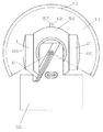
図4、図5は本実施例におけるヘキサ巻の円筒形状の巻線を使用したスロットレスのコア付きモータの図であって、図4は断面図、図5は側面図である。このスロットレスのコア付きモータはサーボ制御のブラシレスモータであって、センサレス駆動タイプのアウターロータ回転タイプある。この実施例のモータは超音波素子駆動モータであって、超音波診断装置のプローブ先端に搭載のモータ例である。説明のために図4、図5にはウインドウケースやハンドルなどケーシング類は省略してある。
【0052】
図4、図5においてそのコア48は固定側であって、駆動マグネット49の付いているロータフレーム50が回転側である。ロータフレーム50は小判形状をしていて、内側には半円状の駆動マグネット49が2個対向して取り付けられている。ロータフレーム50の小判形状でフラットになった外周面には超音波素子1、2が取り付けられている。そのためロータフレーム50が駆動軸9(シャフトともいう)を中心に回転すると、そのロータフレーム50に搭載の超音波素子1、2も駆動軸9を中心に回転する。ロータフレーム50は軸受51、52で回転支承されている。軸受51はロータフレーム50に設けられた軸受ボス部53に取り付けられている。もう一方の軸受52はロータ側板54に取り付けられ、そのロータ側板54はロータフレーム50に嵌合挿入して装着される。
【0053】
モータを制御するために、ロータ側板54にはエンコーダマグネット16が取り付けられていていて、エンコーダマグネット16表面に多数の等間隔に磁極が着磁されている。エンコーダマグネット16の外周に対向するように磁気抵抗素子(MR素子、AB相MR素子ともいう)17が磁性材の取付台55に取り付けられて、その取付台55をベースハウジング56に取り付ることで、エンコーダマグネット16の外周と微少な隙間を設けてAB相MR素子17を配置固定する。
【0054】
また駆動ロータの回転位置情報を知るための相対位置情報手段として磁気式エンコーダが組み込まれている。その磁気式エンコーダは駆動ロータ側にエンコーダマグネット16とベースハウジング56側にAB相MR素子17とで構成されている。エンコーダマグネット16の材料はプラスチックマグネットであり、ベース樹脂として12ナイロン系を使用している。
【0055】
駆動マグネット49の漏洩磁束の影響をエンコーダ出力に受けないために、エンコーダマグネット16とAB相MR素子17との隙間が非常に狭く設定している。その隙間が狭いために、エンコーダマグネット16の膨潤や切削振れや組立振れなどの影響を少なくする必要がある。ロータ側板54にエンコーダマグネット16を接着固定した状態で組加工して部品による振れを小さくしている。また、エンコーダマグネット16のプラスチックマグネットでのフェライトの含有量を大きくした材料を使用している。つまりエンコーダマグネット16については、超音波伝播媒質中で使用されるので膨潤影響を考慮して、79%以上磁性材を含有したものを使用している。
【0056】
相対位置情報手段として磁気式エンコーダが組み込まれ、その磁気式エンコーダの位置検出素子はAB相MR素子17である。そのAB相MR素子17はA相、B相の2チャンネルの信号が得られるMR素子であって、A相とB相の位相差は90度のものである。A相とB相との位相差が90度であるために、駆動ロータの回転方向をその位相差から求めることができる。そのために、ロータフレーム50に取り付けた超音波振動子1、2の回転位置情報を知ることができる。回転着磁機で多極に着磁されたエンコーダマグネット16の外周とAB相MR素子17は対向配置されている隙間は50μm程度であり、超音波伝搬媒質中で駆動するので、大きなゴミがあればその隙間に入り込んだりするので、オイル洗浄した上で組み込みがなされる。そのエンコーダマグネット16の磁極数に相当した数の信号をAB相MR素子17から検出し、モータの制御信号として駆動モータを制御させる。
【0057】
そのAB相MR素子17の信号は可撓性基板(AB相FPCともいう、図示せず)を通って駆動ロータの近傍の中継アンプ基板14で一旦増幅して、さらに正弦波波形の信号を矩形波処理する中継調整基板に接続し、そこからケーブルを使用した長い配線処理をしてコネクタボックスに内蔵した駆動モータの制御駆動回路に接続し、さらにコネクタボックスを超音波診断装置本体に装着して、駆動モータの制御駆動回路に電力を供給する。また、装置によってはMR信号の矩形波信号はシステム本体側にも接続して、パルスの情報を伝達している。
【0058】
超音波振動子1、2への送受信信号を駆動ロータの外部に取り出すために、ロータリトランス21が構成されている。ロータリトランス21のロータ側トランス22をロータフレーム50の側面に取り付け、ステータ側トランス23はベースハウジング56側に取り付けられている。ロータリトランス21は2チャンネル構成であるので、トランス対向面にはリング状のコイル溝が2本それぞれのトランスには形成されていて、そのリング状の溝には巻線が数ターン平面上に配置されている。ロータ側トランス22の巻線はコイル溝66、67の下にあけられた穴59を通ってロータフレーム50側に引き出されてロータ側トランスの裏面に貼られたFPC68に接続される。また、超音波振動子のリード線もロータ側トランス裏面に貼られたFPC68に接続し、ロータ側トランス22の巻線を超音波振動子に導通接続する。ステータ側トランス23もロータ側トランス22の巻線に対向する位置にリング状のコイル溝69、70を設け、そのコイル溝69、70に巻線71を数ターン巻配置し、その巻線の端はステータトランス側のリング状溝の奥に設けた穴60に通して、ステータ側トランスの裏側のFPC72に接続する。そのFPC72からはシールド線などを使用して超音波診断装置本体側へ接続する。
【0059】
本実施例では超音波振動子は2個を使用している。さらに、2種類の超音波振動子を搭載することができるので、1つの超音波プローブで2つの距離分解能の異なったものとして扱えるなどの長所がある。。
【0060】
一般に距離分解能は周波数が高いと向上するが、周波数が高くなると超音波の減衰が大きくなるために、深度の深い部分で診断ができなくなるので、1つの超音波プローブで振動数の異なる超音波振動子を切り換えて使用することができるために、より便利な超音波診断が可能となる。
【0061】
また、ロータフレーム50に取り付けた超音波振動子1、2は駆動軸9に対して180度離れた位置に取り付けられる、1方の超音波振動子から放射した超音波がもう一方の超音波振動子でも受信され、超音波の受信信号にノイズとして入らないように、2個の超音波振動子の相対角度位置を180度にしている。送信された超音波振動子はその反射信号を受信するが、反射信号をもう一方の超音波振動子で受信すると、その信号はノイズとなるために、複数個の超音波振動子を使用する場合は相受信は同一の超音波振動子で行い、他の超音波振動子には受信信号がのらないようにする必要がある。
【0062】
ロータリトランス21場合ではクロストークができるだけ小さくなるようにロータリトランス21の材質や磁性材のリングやショートリングや漏れ磁気回路の遮断など対策をこうじている。クロストークは画像のノイズとなるので、充分な配慮が必要となる。
【0063】
超音波振動子はリード線が2本でていて、1本は電気グランド(GND)であり、もう1本は信号線である。本実施例の超音波プローブでは駆動ロータに超音波振動子が2個取り付けられているので、4本のリード線があるが、電気グランドは共通として取り扱うために3本にリード線として処理できる。超音波振動子は180度離れているので、電気グランドの線同士を容易に接続することはできないのでロータ側トランス22の裏側に設けたFPC68を介して接続している。そのFPC68には4箇所にランドがあって超音波振動子のリード線を半田付け接続する。
【0064】
駆動マグネット49に対向するように円筒状のコア48が駆動軸9(シャフト)に固定されている。そのコア48は絶縁されていて、コア48の外周部には円筒状の巻線61が取り付けられている。その巻線61は円筒状のヘキサ巻の巻線である。
【0065】
コア48は円筒状のコアであるので、スロットのあるコアと区別され、スロットレスコアと呼ばれている。このスロットレスコア48には、絶縁膜62が膜状に施されている。実施例ではこの絶縁膜62はエポキシ樹脂の電着塗装膜で、巻線61とコア48との電気絶縁を目的にしたものであるので、膜厚が厚い方が良いが、膜厚が厚いと巻線61とコア48の間に隙間が生じ効率が低下することになるので、膜厚はできるだけ薄くするような工程を採用している。絶縁膜はスプレー塗装によっても膜形成が可能である。絶縁膜62を形成した電着塗装膜、真空蒸着膜などが使用される。
【0066】
電着塗装膜は絶縁性の優れた膜であって、工業的には比較的に容易に膜形成できるうえに、電着塗装膜は耐環境性が優れているために空気以外の環境たとえば油などの環境下でも、モータ使用が可能となる。絶縁に絶縁テープをする場合は油などの環境下では粘着剤が特性劣化するために使用できないが、電着塗装膜では油などの環境でも問題なく使用できる。
【0067】
コアに電着塗装を施す工程の例を以下に説明する。
【0068】
浴槽に水溶性又は水分散型塗料を入れ、コアを浴槽に侵漬し、導電性のコアの塗装する箇所に電極を取り付け、浴槽に付属する対極との間に通電すると、電荷を持った樹脂粒子は電気泳動によってコアに移動して析出する。これを水洗して焼き付ける。
【0069】
浴槽の組成や温度、通電条件を適正な水準に管理すると、塗膜厚の調整が容易でばらつきの少ない電着塗装膜ができ、10μmで公差±5μmでも管理できる。コアは外周部にも電着塗装膜がつくので、電着塗装膜を管理すれば、モータ組立特性上問題にはならない。薄い電着塗装膜の場合、電着塗装膜でコアと巻線との絶縁を持たせるためには、コアエッジ部のエッジカバー率があまり高くないので絶縁膜の強度には注意が必要である。
【0070】
また、電着塗装膜ではなく、蒸着重合薄膜を施すこともある。その蒸着重合薄膜は対環境特性が優れているので、油の中や水の中などに使用される場合には採用される膜である。
【0071】
その蒸着重合薄膜について、説明をする。蒸着重合法は、物理的な真空蒸着法を基に熱エネルギーによりモノマーを蒸発、活性化させ、基材上でモノマーを重合させることにより高分子薄膜を作製する方法である。この方法は高分子薄膜が単純な装置で製作できるので本願のモータコアの絶縁や電子部品材料へ応用ができる。モータのコアの絶縁膜に高分子薄膜を工業的に処理するためには、膜厚の制御性、均一性、大面積化、処理速度の高速化、膜性能の再現性などの条件を満足する方法が要求される。
この蒸着重合法は次のような特徴がある。
(1)無媒体、無溶媒で重合できること。
(2)真空中であるので不純物の混入がさけられ高純度の薄膜ができること。
(3)薄膜が容易に得られること。
(4)分子配列の制御が可能であるので薄膜制御性が良い。
(5)ドライプロセスである。
(6)薄膜の電気特性は溶液法で作製した膜と同等である。
(7)難加工性高分子の薄膜法として最適である。
(8)マスク蒸着が可能であるため膜のパターン形成が簡単にできる。
【0072】
モータのコアの場合は形状が複雑であったりするので、全方向同時蒸着重合法が用いられる。この全方向同時蒸着重合法は、基材や真空槽壁をモノマー分子の蒸発温度以上に加熱しておき、この中に2種類のモノマーを同時に導入し、両者が基材上で反応して蒸気圧の低い二量体や三量体となり基材上に付着し、さらに反応して高分子の薄膜を成長させる。モノマー分子が真空槽全面化から蒸発するので、複雑な基材にも均一に薄膜が形成できる。
【0073】
またモータのコアに使用される薄膜には、ポリアミド、ポリアゾメチル、ポリ尿素、ポリオキサジアゾール、ポリウレタン、ポリエステルなどに加えて、ポリイミド、フッ素化ポリイミド、ベンゾシクロブテン、フッ素化アモルファスカーボン、有機ガラス、パリレンなどが使用される。
【0074】
真空での蒸着重合法による薄膜は、コアの角部のカバーコート率は良好であるので、巻線とコアとの絶縁が確実にできる。
【0075】
コア48は絶縁されていて、コア48の外周部には円筒状の巻線61が取り付けられている。その巻線61は円筒状のヘキサ巻の巻線である。巻線61のタップはコア48の端面に設けられたFPC63を介してリード線64に接続され、そのリード線64は駆動軸9の溝を通ってロータの外に引き出される。
【0076】
駆動モータの回転部は駆動軸9を中心に回転し、ロータフーム50の外周部に取り付けられた超音波振動子1、2も駆動軸9を中心にして回転する。その超音波振動子1、2は、トランスデューサとも呼ばれて、超音波プローブの中核をなす部品である。超音波振動子1、2の先端には音響レンズ65がついている。屈折の現象を有効に利用するのが音響レンズ65であって、超音波は液体中よりも固体中での音速が早いために振動子表面には凹型の音響レンズで超音波ビームを集束させている。凹型の音響レンズ以外にも平面型音響レンズや凸型音響レンズを貼り付けられた超音波振動子が使用される。
【0077】
超音波振動子1、2のビームは駆動モータの駆動軸9に対して直交してラジアル方向にスキャンされる。そのためにビームの軌跡面11は駆動軸9に直交しているが、ハンドルの軸に対しては平行な面となっている。したがってハンドルの軸に対しては平行な面となるビーム軌跡面11の超音波断層画像が得られる。超音波振動子1、2は駆動モータで回転されるのでその時の超音波振動子のビーム軌跡面11が駆動軸9に対して直交する面である。図5から分かるように、超音波振動子から超音波を送受信して得られる超音波振動子配列方向の超音波断層画像取得領域は360度の全周ではなくベースハウジング56に妨げられて、ある範囲の超音波画像しか得られない。その範囲では超音波振動子で走査できる超音波走査可能領域を表す。実際の超音波診断装置では反射の問題などを考慮して幾何学的な角度よりも少し小さな設定となっている。この角度を走査角度73という。本実施例場合では角度は220度となっている。
【0078】
ベースハウジング56は金属粉末射出成形法(Metal Injection Molding=MIM)によって焼結金属から形成されている。本実施例のベースハウジング56は3次元的な複雑な形状であるうえに、駆動モータを支承するために支持剛性が必要である上に、超音波振動子の回転軸の位置寸法が安定であることも重要な要件であり、MIMを採用して製作をした。
【0079】
MIMで製作するために次のポイントで金型形状、製品成形条件などを検討し、下記のような観点で、製品形状と金型製品形状を設計した。
(1)部品の厚みができるだけ均一な厚みになるようにする。
(2)円弧形状が多い形状であっても離形を優先にする。
(3)支柱部と支持部を設けた形状とする。
(4)焼結後の2次加工箇所をできるだけ少なくする。
(5)抜きテーパを0にする箇所を設け精度向上をはかる。
(6)軽量であること。
【0080】
また、MIMは、加熱溶融された熱可塑性の物質を高圧・高速で金型内へ射出し冷却することで部品を生産するプラスチック成形方法に類似したものであり、金属の素材を微粒粉末(金属粉末)に粉砕し、その金属粉末とバインダーとなる樹脂あるいはワックスなどの流動性を付与させる有機系物質を混練し、得られた素材を加熱して溶融し、造粒し、プラスチックと同様に射出成形をする。その後、得られた成形体を熱分解方式などで脱脂した後、焼結を行うことで金属部品を生産する方法である。
【0081】
ベースハウジング56の材料には、強度が必要であり、超音波伝播媒体に対して物性が安定であり材料として、ステンレス鋼であるSUS630、SUS303、SUS304、SUS304L、SUS316、SUS316L等、非鉄系材料WC−Co、W−Cu−Ni、W−Fe−Ni、Tiなどが使用できる材料が選定できる。医療機器などには防錆の関係でSUS304Lを使用した。
【0082】
一方、バインダーとしては、例えば、ポリエチレン、ポリプロピレン等のオレフィン系樹脂、アクリル系樹脂、ポリスチレン等のスチレン系樹脂、ポリアミド、ポリイミド、ポリエステル、ポリエーテル、液晶ポリマー、ポリフェニレンスルフィド等の各種熱可塑性樹脂や、各種ワックス、パラフィン等のうちの1種または2種以上を混合して用いた。
【0083】
ベースハウジング56のバインダーの一例としてアクリル樹脂とポリスチレン等を配合し、添加量を変えながら実験した結果、寸法の低下が見られず成形体を焼結することができる添加量は35〜55vol%であり、ベースハウジング56は添加量45vol%程度にして製作した。
【0084】
金属粉末とバインダーの混練物には、ベースハウジング56のブランク形状でMR素子取付部やステータ側トランス取付部は抜きテーパのないストレート部を成形体に求めるために、可塑剤、潤滑剤などの添加物を微量添加している。
【0085】
図4、図5から、駆動モータのモータリード線64は駆動軸9の溝から外部に引き出されて、モータリード線64は駆動モータが3相でΔ結線であることから、3本であり、その個々のモータリード線は所定の中継アンプ基板14に半田接続さる。駆動モータの電力は超音波診断装置本体から供給される。つまり、本体からコネクタボックスの駆動モータ制御駆動回路に供給されて、その駆動モータ制御駆動回路のコイル出力部からハンドルの中継調整基板を経由して、さらに中継アンプ基板も経由して、モータリード線64(一般にU相、V相、W相として区別されている)に接続される。モータリード線64はモータの駆動電流が流れるために、リード線抵抗が小さなものを使用している。すなわち、導体を太くしている。
【0086】
図4で示すように超音波振動子1、2への送受信信号を駆動ロータの外部に取り出すために、ロータリトランス21で構成されている。ロータリトランス21はロータ側トランス22をロータフレーム50に取り付けられ、ステータ側トランス23がベースハウジング56側に取り付けられている。
【0087】
超音波振動子が2個搭載されているのでロータリトランス21は2チャンネル構成であるので、トランス対向面にはリング状の溝が2本それぞれのトランスには形成されている。
【0088】
ロータ側トランス22の表面に同心円状にコイル溝66、67が形成され、そのコイル溝66、67には、溝に適した半径のコイルが装着される。駆動モータをウインドウケース内に収納するために、ロータリトランス21は円板形状のものであって、できるだけ薄いものを採用した。コイル溝66、67に配置するコイルの処理方法によっては、モータのトルク発生スペースが小さくなるので、特性の低下を少なくするように、FPC68を使用して、コイル端末の接続を行った。
【0089】
ロータリトランス21のロータ側トランス22を薄いスペースの中に構成することができるので、小型で軽量な超音波振動子を駆動する駆動モータができ、その駆動モータを超音波プローブの先端に内蔵することができる。
【0090】
ステータ側トランス23もロータ側トランス22と同様に2チャンネルの構成になっている。ステータ側トランス23のトランス対向面には、ロータ側のコイル溝と対向する半径位置に2本のコイル溝69、70が形成され、そのコイル溝69、70には、溝に適した半径の巻線71が装着されている。巻線71は非磁性材である接着材にてコイル溝に固定され、ステータ側トランス23の巻線71の端末線は溝の下にあけられた穴60を通ってステータ側トランス23の裏側に引き出され、ステータ側トランス23の裏側に貼られたFPC72に半田付け接続される。そのFPC72を介して、超音波診断装置本体側へと接続される。ステータ側トランス23の裏側のFPC72は、ベースハウジング56の支柱部に支障がない位置でシールド線に半田接続され、超音波診断装置本体側へ接続する。
【0091】
コイルの引き出しを裏面にすることで、ステータ側トランスを薄いスペースの中に構成することができるので、小型で軽量な超音波振動子を駆動する駆動モータができ、その駆動モータを超音波プローブの先端に内蔵することができる。
【0092】
超音波診断装置の使用周波数は1MHz〜10MHzであり、家電製品に比べて周波数が高い。したがって、使用するトランスの材料は初透磁率μiの周波数特性が使用周波数の範囲でフラットな材料がいいことから、初透磁率は比較的小さな材料が使用される。超音波診断装置のロータリトランスの初透磁率は650以下のものが好適である。
【0093】
本発明では、駆動モータの駆動制御するために、磁気式エンコーダを使用して駆動モータの位置情報を入手している。駆動モータのロータフレームに超音波振動子を直に取り付けているために、ロータフレームの側面側に設けた磁気式エンコーダで得られた位置情報は超音波振動子の正確な位置情報として使用できる。そのため駆動モータの制御に使用する位置情報を、超音波振動子から得られる画像情報の位置情報として使用する。
【0094】
モータの磁気式エンコーダに使用するMR素子が90度位相のものであるので、信号を処理することでより位置情報数の多い方法が可能である。
【0095】
まず、駆動モータの位置情報について説明する(図1〜図5の符号を使用する)。
【0096】
駆動モータ3には基準位置情報を知るための基準位置手段として磁性材のZ相ピン12がSUM24LやSUYなどの磁性材のロータフレーム50の外周部に取り付けられている。このZ相ピン12は円筒形状した部分をロータフレーム50の外周に設けられた円筒の穴に挿入して取り付けられ、駆動回転方向に対して先端鋭角になるようにカット面57が両方に設けられている。このZ相ピン12への磁束は駆動マグネット49から得ている。Z相ピン12を検出するZ相MR素子13が磁性材の取付台58を介してベースハウジング56に取り付けられている。Z相MR素子13の信号は可撓性基板(または、Z相FPCともいう、図示せず)を通って中継アンプ基板14に接続され、中継アンプ基板14から超音波プローブのハンドル6にある中継調整基板7に接続されて、その中継調整基板7からシールドケーブルを通ってコネクタボックス18にある駆動モータ制御駆動回路19に接続される。中継アンプ基板14ではZ相MR素子の信号を増幅している、さらにその増幅した信号を中継調整基板7において、矩形波処理される。図6にZ相MR素子の増幅回路図と矩形波処理回路図の一例を1つの回路図中で表す。図6はAB相MR素子信号の増幅回路図と矩形波処理回路図も表している。AB相MR素子側についての回路の詳細説明は後述する。図6の回路において、13はZ相MR素子、17はAB相MR素子、77はZ相MRオペアンプ、78はA相MRオペアンプ、79はB相MRオペアンプ、80はZ相MRコンパレータ、81はA相MRコンパレータ、82はB相MRコンパレータである。
【0097】
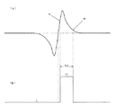
磁性材のZ相ピン12とZ相MR素子13で構成されていて基準位置手段は、磁性材のZ相ピン12が1つであるために、Z相MR素子13では駆動ロータの1回転に1パルスの信号が検出される。そのZ相MR信号の信号レベルが小さい、すなわち入力端子83の電圧は小さくので、モータの近くの中継アンプ基板14に搭載のZ相MRオペアンプ77で信号増幅される。オペアンプ後の波形は1パルスと言っても、MR素子の抵抗に変化がない時には抵抗86、87で決まる電位になる、通常は抵抗86、87は同じ値のものを使用する関係で回路電圧Vccの中点電位示す。例えば回路印加電圧5Vの場合は約2.5Vが中点電位となる。Z相ピン12がZ相MR素子13を通過するときには図7(a)のように一度盛り下がって、中点電位以上に盛り上がるような波形になる。Z相MR素子13から直ぐの信号は出力幅が小さいので、外部ノイズの影響を受けやすいので、中継アンプ基板14をベースハウジング56の近くに配置して増幅するようにしている。
【0098】
増幅後の信号振幅はZ相ピンの調整などによって変化するので、Z相ピン12はZ相MR素子出力確認後接着固定する。増幅後のZ相信号は中継調整基板7の波形整形回路74で矩形処理される。中継アンプ基板14で増幅されたZ相MR素子13の信号が波形整形回路74に入力される。入力された入力信号は抵抗とコンデンサで構成されるフィルタを通って、Z相MRコンパレータ80に入力され、可変抵抗器90で作られる基準電圧と比較され、Z相MRコンパレータ80の出力信号は入力信号が基準電圧より高い場合はZ相MRコンパレータ80の出力は「H」レベル(High)になり、低い場合は「L」レベル(Low)になる。図7(b)のようなZ相MRのコンパレータ出力波形が得られる。図7に見られるようにZ相MRコンパレータ80はヒステリシスがあるために、コンパレータ出力の立ち上がり時の入力電位(s点での電位)とコンパレータ出力のたち下がり時の入力電位(e点の電位)とは同じ電位にはならない。
【0099】
矩形処理された信号は0−5Vの矩形波信号であり、外部からのノイズの影響を受けにくい。
【0100】
さらに、駆動モータの回転制御情報を超音波振動子の角度情報として使用可能なように、超音波振動子の位置を確定する必要がある。その方法としては、
下記のいずれかでもって、ロータの対する超音波振動子の取付位置を絶対位置として確定することが可能となる。
(a)ロータのZ相基準情報位置に合わせて、超音波振動子を取り付ける。
(b)超音波振動子の取付位置を基準にしてロータのZ相基準情報を合わせる。
【0101】
以下には、超音波振動子の取付位置を基準にしてロータのZ相基準情報を合わせる方法を説明する。図8、図9を参照のこと。
【0102】
図8にはZ相調整時のロータの超音波振動子取付面とベースハウジングの取付面とのなす角度を90度にした基準ジグで駆動モータを取付ける。ロータフレーム50の超音波振動子取付面91とベースハウジング56の取付面92とは90度で固定されたものであるので、超音波振動子の機械的な絶対位置状態が決定できる。その状態でZ相MR信号を関連づけるために、可変抵抗器90でZ相の「H」レベルである幅をあらかじめ決めておき、この幅が決定したらZ相MR素子13を取り付けているビス93をゆるめて、前記90度ジグ固定状態でZ相MR素子コンパレータ80の出力電位が「H」レベルになるように、図8に示すZ相MR素子移動調整方向にMR素子取付台の位置をずらし、Z相MR素子コンパレータ80の出力電位が「H」レベルになる位置でビス93をしめつけ固定する。その時は、Z相MR素子のコンパレータ信号が「H」レベルの時は、ベースハウジング56の取付面92に対して90度位置に超音波振動子取付面91が位置していることを示す。Z相調整時の幅tzを大きくして調整すれば、その幅が超音波振動子の絶対位置情報の誤差になるので、その幅tzを小さく規定すればいい。作業性の問題で、ある範囲に決まられている。
【0103】
上記のようなZ相調整をしない場合、超音波振動子の絶対基準位置94に対して、図9(a)や図9(c)に見られるようにZ相MRのコンパレータ出力が「H」レベルが確定しないので、Z相調整を行うことで図9(b)のように超音波振動子の絶対基準位置94がコンパレータ出力が「H」レベルの位置に調整することができる。
【0104】
Z相コンパレータ信号の立ち上がり位置は駆動モータの回転基準位置になるように組み立てたことになる。Z相の矩形波の立ち上がりの位置を例えばロータフレームの超音波振動子の取付面に対して90度位置に調整することによって、Z相の立ち上がりから駆動ロータの基準位置が明確になり、さらには超音波振動子1、2の回転基準位置も明確になる。このZ相信号により基準位置を元に、超音波振動子1、2の位置を決めておけば、超音波振動子の回転位置の基準を個々の超音波プローブ間の相違なく決定することができる。
【0105】
駆動モータ3には基準位置情報を知るための相対位置情報手段として磁気式エンコーダ15が組み込まれている。その磁気式エンコーダ15はエンコーダマグネット16と位置検出素子のAB相MR素子17である。そのAB相MR素子17はA相、B相の位相差は90度のものである。A相とB相との位相差が90度であるために、駆動ロータ4の回転方向をその位相差から求めることができる。
【0106】
図6に示されたAB相MR素子の増幅回路と波形整形回路の一例は、A相とB相は回路的に同じであるためにA相でもって説明をする。図6の回路において、17はAB相MR素子で、A相MR素子の出力は入力端子84(B相の入力端子は85である)の位置の電圧である。回転着磁がなされているのでエンコーダマグネット16の磁極をAB相MR素子検出した場合、正弦波波形の信号が得られる。その信号をA相オペアンプ78(B相オペアンプ79)で増幅すれば、信号振幅でアンプ倍率に基づいて約1.6V程度の正弦波波形信号が得られる。たとえば、エンコーダマグネット16は300極である場合、AB相MR信号も300パルスとなるので、駆動ロータの位置情報としては1回転あたり300パルスの分解精度の信号が得られる。A相とB相とも300パルスであって、90度の位相差を持っている。
【0107】
増幅後のA相信号(B相信号)は中継調整基板7の波形整形回路74で矩形処理される。中継アンプ基板14で増幅された入力信号は抵抗とコンデンサで構成されるフィルタを通って、A相MRコンパレータ81(B相信号はB相MRコンパレータ82)に入力され、可変抵抗器95で作られる基準電圧と比較され、A相MRコンパレータ81の出力信号は入力信号が基準電圧より高い場合はコンパレータ81の出力は「H」レベルになり、低い場合は「L」レベルになる。図10(b)のようなA相MRのコンパレータ出力波形が得られる。図10(c)はB相MRコンパレータ82のコンパレータ出力波形である。A相の波形とB相の波形との位相差は90度である。モータを逆回転させると位相差は逆位相になる。
【0108】
超音波振動子の絶対位置はZ相のMR信号から決定させるが、超音波振動子からの相対位置情報の信号の始めの位置を超音波振動子の位置にできるだけ近くするために、図10に波形整形回路74からはA相、B相、Z相の矩形波形が得られる。図10(a)はZ相MRのコンパレータ出力波形である。
【0109】
超音波振動子の絶対位置が正確であれば、得られた超音波診断画像の画像位置情報が正確になる。図10ではZ祖信号の立ち上がり96の位置が次関係になるようにAB相MR素子波形を調整する。Z相位置調整は超音波振動子の位置関係づけをすでに終了しているので再調整は誤差が大きくなるのでしない。そのためにAB相MR素子の方を調整することになる。
【0110】
下記(a)(b)を満足するように調整することで、Z相MRコンパレータ出力の立ち上がりからB相MRコンパレータ出力の立ち上がりまでの時間は、A相MR信号の周期の4分の1以下の時間になる。
(a)Z相のコンパレータ出力が「H」レベルの時間幅のときに、B相MRコンパレータ出力の立ち上がりがあるようにする。すなわち、B相の立ち上がりをZ相MRコンパレータ出力の「H」レベルで囲む。
(b)Z相のコンパレータの立ち上がりがA相MRのコンパレータ出力の「H」レベルにある。
【0111】
この駆動モータ3は回転数300r/minから1800r/minまで数段階に切り換えて回転駆動する。たとえば、エンコーダマグネット16が300極の磁極である場合、AB相MR信号もそれぞれ300パルスとなる。駆動モータの駆動軸と超音波振動子の回転軸が同一軸であるので、ばらつきもなく回転角度精度の良好なものとなり、画像もその信号をトリガーに使用する場合はかなり画質の良い超音波診断画像となる。超音波振動子の画像位置情報とモータの回転位置情報と連動することで、駆動モータが回転変動しても超音波振動子の画像情報を正確な角度情報として使用でき、画質及び精度の良い超音波画像が得られる。AB相の信号とZ相信号を波形処理して、矩形波信号として、超音波診断装置本体へ伝達することで、超音波振動子の画像位置情報とモータの回転位置情報と連動することができる。
【0112】
また、MR素子からの出力を増幅してから矩形波処理を行ったが、超音波プローブの構造によっては増幅回路をモータの直近に設けることができない場合があり、そうした場合はMR素子からの信号を直接矩形波処理することもある。
【0113】
(実施例2)
本発明の実施例は、超音波プローブ先端に内蔵された振動子をモータで回転することにより断面位置を任意に変えることのできるいわゆるマルチプレーン型の超音波プローブ及び超音波診断装置に関するものである。
【0114】
図11は本発明の一実施例における走査型超音波プローブを使用した超音波診断装置の全体を示す概略ブロック図である。また、図12に体腔内挿入型超音波プローブの外観斜視図を示す。この超音波プローブは、食道や腸などの消化器官診断や血管へ直接挿入して振動子を走査させて超音波診断を行うものである。図13は超音波振動子を駆動する駆動モータの断面図である。
【0115】
本実施例の超音波診断装置は超音波プローブと本体システム部(または本体装置)から構成される。超音波プローブは先端(または挿入部)101とハンドル(または操作部、手元操作部)102とコネクタボックス103と挿入管(または導中部)104とケーブル105で構成される。超音波プローブの先端101には超音波振動子106を回転駆動させる駆動モータが構成されている。その駆動モータには超音波振動子106とともに回転する駆動するロータ部分(駆動ロータとする)107が構成され、駆動ロータ107を支持するベースハウジング108が超音波プローブ先端に内蔵されている。先端101からハンドル102まではフレキシブルな挿入管104で構成され、その挿入管104は血管や口腔内に挿入される細長い管であってシースチューブとその中を電気信号線が通っている。超音波プローブのハンドル102にはコントローラノブ109が構成される。ハンドル102にはケーブル105を介してコネクタボックス103が接続され、コネクタボックス103には駆動モータ制御駆動回路110があり、その駆動モータ制御駆動回路110には位置検出信号処理回路111とモータ駆動回路112とプローブCPU113が構成されている。そのコネクタボックス103を介して超音波診断装置本体に超音波探触子が電気的に接続される。
【0116】
超音波振動子106は駆動ロータ107の回転部の天面部に取り付けられている、そのため超音波振動子106の回転軸と駆動モータの駆動軸114とは同一の軸となる。駆動軸114に対して超音波振動子106のビームはアキシャル方向に放射させる。超音波振動子106側のビーム放射軸115方向に超音波ビーム軌跡面116を形成する。その駆動ロータ107が回転することで超音波振動子106の超音波ビーム軌跡面116は回転する。その超音波ビーム軌跡面116は駆動軸114に対して平行な面となる。
【0117】
本実施例の超音波プローブは、被検者の体腔内に挿入して体腔内の被検部の超音波画像を得る体腔内用超音波プローブであって、この体腔内用超音波プローブは、先端に超音波振動子106を備えており、超音波振動子106は、予め機械的に決定された回転範囲内の任意角度の超音波断層画像を撮るようになっている。
【0118】
駆動ロータ107の回転位置情報を知ることは、駆動ロータ107に取り付けられた超音波振動子106の位置情報を知ることになる。駆動ロータ107の回転位置は1回転の基準となる基準位置手段と相対位置情報手段を併用して駆動ロータ107の回転位置情報を知ることができる。
【0119】
基準位置手段としてエンコーダマグネット117とMR素子118で構成される。また、相対位置情報手段としてもエンコーダマグネット117とMR素子118で構成される。MR素子はABZ相MR素子であって、Z相MR素子部とAB相MR素子部とが一つのMR素子に形成されている。Z相MR素子部は超音波振動子側に形成され、AB相MR素子部はベースハウジング108側に形成されている。したがって、エンコーダマグネット117も超音波振動子側はZ相磁極部であって、ベースハウジング側はAB相磁極部である。
【0120】
MR素子118のZ相信号は駆動ロータ107の1回転に1パルスの信号が検出できる。そのために駆動ロータ107の基準位置を知ることができる。そのZ相信号は挿入管104を通ってハンドル102、ケーブル105を通って、コネクタボックス103の駆動モータの制御駆動基板110に接続される。中継ボックスの駆動モータ制御駆動回路110にはMR信号の位置検出信号処理回路111とモータ駆動回路112とプローブCPU113とが構成されている。そのMR信号の位置検出信号処理回路111でMR信号は信号増幅されて、さらにプローブCPU113で信号情報処理がなされ、通信信号の情報として超音波診断装置本体側の本体CPU119(またはホストCPU)へ接続される。MR信号は増幅後矩形波処理した信号も使用する場合は、超音波振動子との位置関係を機械的に合わせる超音波プローブに用いる。
【0121】
相対位置情報手段としてMR素子118のAB相検出部と駆動ロータ107側にエンコーダマグネット117とで構成されている。AB相検出部はA相、B相の2チャンネルの信号が得られるMR素子であって、A相とB相の位相差は90度のものである。A相とB相との位相差が90度であるために駆動ロータ107の回転方向をその位相差から求めることができる。エンコーダマグネット117の外周にはAB相磁極とZ相磁極が着磁されている。特にAB相磁極部は多極の磁極が着磁されていて、その磁極数に相当した数の信号をMR素子118から得る。
【0122】
また、AB相、Z相による信号情報はプローブCPU113で加工処理されて、位置情報の通信情報として超音波診断装置の本体システム120に伝達される。本体システム側でも、超音波振動子の位置情報が必要であるので、つまり、画像を表示するためには位置情報がないと表現することができないからである。たとえば、エンコーダマグネット117のAB相磁極が240極の磁極である場合、AB相MR信号も240パルスとなるので、駆動モータの位置情報としては1回転あたり240の分解精度の信号が得られる。Z相信号の1回転に1パルスであるので、Z相の信号を基準にしてAB相のパルスを考えると、AB相パルスが絶対位置情報になるので、その絶対位置情報を通信仕様にあわせたものにすればいい。Z相の位置信号と超音波振動子の位置情報があらかじめ決まっていれば、その絶対位置情報を使用すればいいが、プローブごとに異なっている場合は超音波振動子からみた位置情報になるようにプローブごとに補正を加える。
【0123】
コネクタボックス103は超音波診断装置本体のシステム本体120に接続されて、駆動モータ制御駆動回路110など駆動モータを駆動するための電力を供給している。
【0124】
駆動モータの回転位置情報手段として、実施例に示すようにMR素子を用いた磁気エンコーダ以外に抵抗値の変化を検出するポテンショメータ、光電センサーを用いた光エンコーダなどでもいい。
【0125】
本実施例はプローブ自体を回転させることなく多数の断層面の超音波断層像を駆動モータに搭載して超音波振動子を回転させる超音波プローブが示されている。超音波の走査領域(例えばセクタ状の平面)を回転させることにより、任意の角度の超音波のビーム軌跡面を走査することで超音波断層像得る超音波プローブである。このようなマルチプレーンの超音波断層像得ることができることからマルチプレーン超音波プローブとして区別している。
【0126】
本実施例の超音波振動子106は、複数の超音波振動子が一次元方向に配列されてなる超音波振動子列で構成されていて、その超音波振動子列のパルス駆動手段が駆動モータの位置情報と連動して走査するシステムになった構成であり、その超音波振動子列を駆動モータで回転させている。
【0127】
超音波振動子106から放射した超音波は超音波振動子106の放射面に直交した角度で放射され、生体組織内に入射する。組織内に入射した超音波の一部は組織内において反射した後、前記超音波振動子106で受信され電気信号に変換されて、シールドされた数本の入出力線を伝って、挿入管104、ハンドル102、ケーブル105、コネクタボックス103を経由して、システム本体120の回路に送られる。
【0128】
次に超音波診断装置本体のシステム本体120内の送受信回路部分について説明する。
【0129】
超音波を生体内に送信する場合には、まずパルス発生器121によって超音波パルスの繰り返し周期を決定するレートパルスが出力され、超音波周波数のきまったパルス振動子駆動回路122に送られる。この振動子駆動回路122では超音波振動子に駆動信号を供給駆動して超音波を発生するため駆動パルスが形成される。その駆動パルスによって超音波振動子106から生体内に放射される。
【0130】
超音波振動子106から生体内に放射された超音波は生体内組織にて反射される。その反射超音波を超音波エコーという。送信時に用いた超音波振動子106によって受信され、この超音波エコーの反射強度に相当する微弱な受信信号はシステム本体120内の増幅器123にて増幅されたのちBモード用信号処理回路に送られる。Bモード信号処理回路において振動子出力は対数増幅器124で対数圧縮し、包絡線検波用の検波回路125にて検波され、ゲイン補正用のゲイン設定器126をゲイン制御用コントローラ127で制御されてゲイン補正され、合成回路128で合成されて、A/D変換器129にてA/D変換され、高速画像DSP130で画像処理される。DSP130で処理された座像は一旦画像メモリ131にストアされる。駆動時の複数の画像も画像メモリ131にストアされ、高速画像DSP130を用いて信号処理され、その信号をデジタル・スキャン・コンバータ(DSC)132を介してTV走査用フォーマットに対応した画像データに変換され、テレビモニタ133にて2次元超音波断層画像として表示される。本体装置のシステム本体120には、装置全体の回路を統括するホストCPU119があり、画像データやメモリや駆動モータの位置情報やモータ駆動などを総合的に監視、処理命令などしている。ホストCPU119は本体装置への外部入力操作に伴う入力による、超音波プローブとしての処理を統括していることになる。
【0131】
図12に示す超音波プローブの外観斜視図はマルチプレーン超音波プローブの一例である。被検体に経口的に挿入され、食道及び胃を含む上部消化管から心臓を観察するマルチプレーンTEE超音波プローブ(TEE:Transesophageal Echocardiography)である。挿入管104は屈曲性をもったシースチューブとそのシースチューブの中を電気信号線で構成され、先端101から挿入管104までを体腔内に挿入した状態で超音波診断が行われる。たとえば、超音波プローブの挿入管を口から食道に挿入し、食道近傍の臓器や胃あるいは十二指腸などの超音波診断を行うものであるが、心臓弁の動きは挿入管104を食道に挿入した状態で、駆動モータを回転させれば、超音波振動子によって形成される超音波ビーム軌跡面が回転され、走査画像が得られる。
【0132】
超音波プローブの先端101は超音波透過性を有する窓材からなるウインドウケース134が先端に取り付けられていて、その超音波プローブの先端101は駆動モータと超音波振動子などが内蔵されている。超音波プローブの先端101とハンドル102は屈曲性のある挿入管104で接続されている。ハンドル102は手で持って操作する手元操作部であって、操作のためのコントローラノブ109が構成されている。コントローラノブ109には各種のスイッチが付いていて、いろいろなモードで回転させることができる。コントローラノブ109を回転させると、その回転方向に駆動モータが回転し、かつ超音波振動子も回転するので、回転速度などはコントローラノブ109に設けられたスイッチを操作することで変速を行う。駆動モータの回転停止などのスイッチもコントローラノブ109に付いている。コントローラノブ109の信号はコネクタボックス103からシステム本体120のホストCPU119に送られ、ホストCPU119からそのコントローラノブ109の指令に合わせて駆動モータの制御回路に命令が伝達される。その命令に基づいて駆動モータは制御駆動される。
【0133】
超音波プローブはハンドル102からケーブル105でコネクタボックス103に接続されている。超音波プローブはそのコネクタボックス103を超音波診断装置のコネクタ差し込み口に装着することで、システム本体120に接続される。診断中に超音波プローブがはずれないようにロック機構のついたノブ135があり、装着後はノブ135を回してコネクタボックス103を本体にしっかりとロックする。
【0134】
従来の超音波診断装置の場合では手元操作部では使用頻度の高い基本操作だけが行えるようにしていたが、実施例ではプローブ側に手元操作により指令内容を処理して指令動作をさせることができるので、手元操作でもって超音波振動子の全部の操作ができる。手元操作では複雑になることや複合操作などの場合には超音波診断装置本体の操作部から行うことができるようになっている。操作機能を手元操作部に持たせるようにしている。
【0135】
超音波振動子106はプローブ先端側面に設けられているので、体腔内患部の側面方向を診断でき、かつハンドルの手元操作部のみによるコントロールでも、たとえば90度回転し、挿入軸に沿った断層面の診断(ビーム軌跡面は図12の符号136)と挿入軸に直角方向の診断(ビーム軌跡面は図12の符号137)とを可能にしている。
【0136】
超音波プローブの先端101は体腔内に挿入し易いように円筒形状のなめらかな流線形状をしている。この挿入管104やケーブル105は、超音波振動子と超音波診断装置本体とを接続する入出力線と駆動モータを駆動制御するための電気制御線とエンコーダなどの信号線と衝撃検出用や温度センサの信号線などをコネクタボックス103に伝達するフレキシブルなケーブルであって、被覆により保護され、かつシールドが施されている。
【0137】
図13は本実施例におけるコア付きでアウターロータ回転タイプのブラシレスモータの断面図である。このモータは超音波振動子駆動モータであって、超音波診断装置のプローブ先端に搭載のモータ例である。
【0138】
図13において、超音波振動子106は素子ホルダー138の筐体の枠中で構成されていて、駆動モータのロータフーム139の天面部に取り付けられ、駆動軸114を中心にして回転する。その超音波振動子106の先端には音響レンズ140がついている。屈折の現象を有効に利用するのが音響レンズ140であって、超音波は液体中よりも固体中での音速が早いために振動子表面には凹型の音響レンズで超音波ビームを集束させている。凹型の音響レンズ以外にも平面型音響レンズや凸型音響レンズを貼り付けられた超音波振動子が使用される。超音波振動子106の信号線は中空の駆動軸114の軸中央の穴を通って、駆動モータの外部に引き出される。
【0139】
超音波振動子106のビームは駆動軸方向に放射させる。超音波振動子106側のビーム放射軸115方向に超音波ビーム軌跡面116を形成する。ロータフレーム139に天面部に取り付けられている超音波振動子106は駆動軸114を中心に回転するので、超音波振動子106の超音波ビーム軌跡面116も回転する。その超音波ビーム軌跡面116は駆動軸114に対して平行な面となる。その超音波ビーム軌跡面116は超音波プローブ挿入軸に沿った断層面のビーム軌跡面136と挿入軸に直角方向のビーム軌跡面137以外の角度にも移動することが可能であるので、任意角度の超音波断層画像を撮ることできる超音波診断装置であって、医療診断に役立っている。
【0140】
本実施例のマルチプレーンTEE超音波プローブは、体腔内部から診断部位の画像を観察可能であるため、経食道用超音波プローブでは肋間の影響あるいは皮下脂肪による超音波減衰の影響を受けることがなく、また血管挿入超音波プローブでは皮下脂肪による超音波減衰の影響を受けることがなく、鮮明な画像が得られるとともに、体腔内の任意方向から見た断層面を観察することができる。
【0141】
本実施例の超音波プローブ一例は、食道に挿入され、心臓の超音波断層像を得るマルチプレーン経食道超音波プローブであって、バイプレーン型の経食道超音波プローブの実施例である。
【0142】
超音波振動子106は、複数の超音波振動子が一次元方向に配列されてなる超音波振動子列で構成されていて、同時にビーム軌跡面116の画像を得ることができる。この超音波振動子列の搭載された駆動モータを以下のような動作モードで駆動させることで、複雑な画像診断が可能となる。
(a)定速回転動作
(b)ステップ動作(1度、2度、3度)
(c)15度バイプレーン動作
(d)90度バイプレーン動作
(e)外部同期バイプレーン動作
(a)の定速回転動作は任意時間での角度位置の2次元画像を複数枚合成して3次元画像処理を行うことができるようにした動作モードであって、心臓の大きさや患部疾患の大きさや方向などを把握することができる。
【0143】
(b)のステップ動作は一定角度間隔の2次元画像を観察するものである。この2次元画像を複数枚合成して3次元画像処理を行うことができるようにした動作モードであって、心臓の大きさや患部疾患の大きさや方向などを把握することができる。
【0144】
(c)の45度バイプレーン動作は個人差などによって心臓の位置や角度が微妙にずれている患者に対して、超音波振動子角度を0°、45°、90°、135°、180°の移動させた画像から患者の基本断面画像を瞬時に得るための測定モード。
【0145】
(d)の90度バイプレーン動作も個人差などによって心臓の位置や角度が微妙にずれている患者に対して、超音波振動子角度を0°、90°、180°の移動させた画像から患者の基本断面画像を瞬時に得るための測定モード。
【0146】
(e)の外部同期モードは心臓の鼓動は各人異なるため、あらかじめ設定した時間で(3)や(4)のバイプレーン動作を行うことができないために、心臓の鼓動に同期させてバイプレーン動作させて、心臓の弁の動きを瞬時に観測する動作モードである。
【0147】
このような動作モードがダイレクトに超音波振動子をモータで駆動することによって可能である。
【0148】
駆動ロータはロータフレーム139には駆動マグネット141を取り付ける垂下部142と駆動軸114と超音波振動子を取り付けるインロー部143が一体で構成されている。リング状の駆動マグネット141は異方性ネオジ磁石でBHmax=39MGOeの特性であって8極の着磁がなされている。駆動マグネット141に対向する位置にコア144がベースハウジング108の中央円筒部145に接着固定される。そのコア144は突極の数6であって、3相になるように巻線146が巻回されている。コア144と巻線146との絶縁のために、コアには電着塗装がなされている。
【0149】
コア144の絶縁膜はエポキシ樹脂の電着塗装膜で、巻線146とコア144との電気絶縁を目的にしたものであるので、膜厚が厚い方が良いが、膜厚が厚いと巻線146とコア144の間に隙間が生じモータ効率が低下することになるので、膜厚はできるだけ薄い膜で形成する。たとえば絶縁膜は50μm以下の膜厚のコアを使用した。電着塗装膜は絶縁性の優れた膜であって、工業的には比較的に容易に膜形成できるうえに、電着塗装膜は耐環境性が優れているために空気以外の環境たとえば油などの環境下でも、モータ使用が可能となる。超音波伝搬媒質内で駆動モータを使用する超音波診断装置において、駆動モータのコアに電着塗装膜や真空蒸着膜を使用することが多い。
【0150】
振動モータの3相のブラシレスモータであって、コアに巻線された線はY結線処理され、そのコモン線はモータ外部には取りださない構成にするために、U相、V相、W相の3本の線を処理する。この3本の線はベースハウジング108に貼られたFPC147に半田付け接続され、そのFPC147を駆動モータの外部に引き出し、その引き出されたFPC147のランドに駆動モータ制御駆動回路からのモータリード線を接続する。
【0151】
超音波振動子106が取り付けられたロータフレーム139は駆動軸114を軸受148、149で回転支承されている。その軸受148、149はベースハウジング108の中央円筒部145の内側に固定され、駆動軸114を中心に回転させることができる。
【0152】
超音波振動子の回転位置を知ることが、画像表示には必要であるので、超音波振動子の取り付けられたロータフレーム139の回転位置情報を知ることである。ロータフレーム139の回転位置は1回転の基準となる基準位置手段と相対位置情報手段を併用してロータフレーム139の回転位置情報を知る。
【0153】
ロータフレーム139の基準位置情報を知るための基準位置手段としてエンコーダマグネット117とMR素子118で構成される。エンコーダマグネット117はZ相磁極部とAB相磁極部が同じエンコーダマグネット117に構成されている。着磁されているために外観から見ることができないが、MR素子を用いることで磁極の極性状態を見ることができる。MR素子118は一つの素子の中にAB相、Z相の検出部が形成されている。Z相の検出部はMR素子118の超音波振動子側に構成されているので、Z相磁極もエンコーダマグネット117の超音波振動子側に存在している。Z相磁極は一回転のうち一カ所に単極の着磁が施されている。単極の磁極をきれいに作成することができない場合はエンコーダマグネットのZ相部の一カ所だけAB相の磁極部と同じ径で構成しこれ以外は一段落としてエンコーダマグネットにしている。
【0154】
Z相MR素子信号はロータフレームの1回転に1パルスの信号が検出される。そのZ相信号は挿入管を通ってハンドル、ケーブルを通って、中継ボックスの駆動モータ制御駆動回路110に接続される。中継ボックスの駆動モータ制御駆動回路110のMR信号の位置検出信号処理回路111でMR信号は信号増幅されて、さらにプローブCPU113で信号情報処理がなされ、通信信号の情報として超音波診断装置本体側の本体CPU119へ接続される。
【0155】
また、相対位置情報手段としてもエンコーダマグネット117とMR素子118で構成される。MR素子はABZ相MR素子であって、Z相MR素子部とAB相MR素子部とが一つのMR素子に形成されている。Z相MR素子部は超音波振動子側に形成され、AB相MR素子部はベースハウジング108側に形成されている。したがって、エンコーダマグネット117も超音波振動子側はZ相磁極部であって、ベースハウジング108側はAB相磁極部である。
【0156】
駆動マグネット141の漏洩磁束の影響をエンコーダ出力に受けないために、ロータフレームの肉厚を厚めにし、エンコーダマグネット117も厚めにしたうえで、エンコーダマグネット117とMR素子118との隙間が非常に狭く設定している。
【0157】
相対位置情報手段として組み込まれた磁気式エンコーダはAB相、Z相を一対のエンコーダマグネットとMR素子で構成している。そのMR素子118のAB相検出部はA相、B相の2チャンネルの信号が得られるMR素子であって、A相とB相の位相差は90度のものである。A相とB相との位相差が90度であるために、駆動ロータの回転方向をその位相差から求めることができる。そのために、ロータフレーム139に取り付けた超音波振動子106の回転位置情報を知ることができる。AB相磁極はエンコーダマグネット117の外周に回転着磁機で多極に着磁されて得られる。エンコーダマグネット117の外周とAB相MR素子118は対向配置されている隙間は50μm程度であり、超音波伝搬媒質中で駆動するので、大きなゴミがあればその隙間に入り込んだりするので、オイル洗浄した上で組み込みがなされる。そのエンコーダマグネット117の磁極数に相当した数の信号をMR素子118から検出し、モータの制御信号として駆動モータを制御させている。
【0158】
また、AB相、Z相による信号情報はプローブCPU113で加工処理されて、位置情報の通信情報として超音波診断装置のシステム本体120に伝達される。本体システム側でも、画像を表示するために超音波振動子の位置情報が必要である。Z相、AB相の信号も基準位置と相対位置を求めるためで、その信号をプローブCPU113で処理することで、Z相の信号位置と超音波振動子の位置を決めておけば、超音波振動子の位置を基準にした位置情報として管理できる。
【0159】
中継ボックスは超音波診断装置本体のシステム本体に接続されて、駆動モータ制御駆動回路など駆動モータを駆動するための電力を供給している。
【0160】
駆動マグネット141の漏洩磁束の影響をエンコーダ出力に受けないために、エンコーダマグネット117とMR素子118との隙間が非常に狭く設定している。その隙間が狭いために、エンコーダマグネット117の膨潤や切削振れや組立振れなどの影響を少なくする必要がある。ロータフレーム139にエンコーダマグネット117を接着固定した状態で組加工してエンコーダマグネットの外周面振れを小さくしている。また、エンコーダマグネット117のプラスチックマグネットでのフェライトの含有量を大きくした材料を使用している。つまりエンコーダマグネット117については、超音波伝播媒質中で使用されるので、膨潤影響を考慮して、79%以上磁性材を含有したものを使用している。たとえば、エンコーダマグネット117の材料はプラスチックマグネットであり、ベース樹脂として12ナイロン系を使用している。
【0161】
たとえば、エンコーダマグネット117は240極である場合、AB相MR信号も240パルスとなるので、駆動ロータの位置情報としては1回転あたり240パルスの分解精度の信号が得られる。A相とB相とも240パルスである。
【0162】
ベースハウジング108は金属粉末射出成形法によって焼結金属から形成されている。成形精度と焼結寸法精度を安定にするために、材料としてSUS316Lを使用している。
【0163】
実施例2の超音波プローブではMR信号の処理回路は中継ボックスに構成するタイプである。他の実施例のように、MR信号の処理のために中継基板を超音波プローブの先端やハンドルに構成するなどの方法もある。また実施例1のように中継基板を分割して配置するなどの方法もある。しかしながら、本発明の主眼である中継ボックスには駆動モータの制御駆動回路基板が構成されている。プローブ側でもってプローブの超音波振動子をコントロールすることができる。Z相、AB相の信号をプローブCPU113で処理することで、超音波振動子の位置を基準にした位置情報として管理できるので、プローブ側と本体側のインターフェース仕様を統一することによって、他の診断用途の超音波プローブでも接続ができる。本体装置も表示機能など解析して他機種に対応すれことによって、1システムでもって、多くの診療科で使用可能な超音波診断装置が提供できることにもなる。
【0164】
このように、本実施例における2次元走査用超音波プローブは軽量かつ小型でプローブ先端に駆動部の主な機構部が内蔵されている。超音波振動子によると、広角な範囲の超音波断層画像が得られる。
【0165】
本実施例の2次元走査用超音波プローブによる2次元的スキャンが可能であり、超音波振動子が固定された駆動モータの回転にともなって、駆動モータ側のエンコーダから回転角度信号が超音波診断装置に伝送され、2次元の超音波断層画像が得られる。
【0166】
実施例2ではAB相MR信号の増幅回路を設けているが、回路や信号レベルの関係から増幅せずに、原信号を直に波形整形回路を用いて矩形波処理をすることで、より小型の超音波診断装置ができる。
【0167】
実施例1、2ともAB相MR素子以外にZ相MR素子を使用しているが、それはZ相MR信号で絶対位置情報を設定している。Z相MR素子を使用しない方法でロータの絶対位置を設定する方法は、機構的に複雑な場合が多い。本発明のような場合は以下の条件の場合で絶対位置を可能とした。
(a)ロータの回転を規制し、その規制端点を座標原点とした。揺動運動の超音波診断プローブの場合は可能である。すなわち、実施例2に示すような経食道超音波プローブは連続回転をしなくてよい為である。
(b)コアの通電をある設定された条件でおこない、ロータをロックさせ、そのロック状態で超音波振動子を取付る。その位置を座標原点にしておけば、その位置から相対情報をもとに角度位置情報を確定していけばよい。
【0168】
上記のような超音波プローブは先端に搭載した駆動モータの制御情報と連動して超音波振動子の位置情報に用いて座像処理をすることで、位置情報の正確な超音波プローブができ、その超音波プローブを用いた超音波診断装置を提供することが可能となり、医療分野に貢献するものとなる。
【0169】
【発明の効果】
上記実施例の記載から明らかなように、
(1)電子−機械走査式の2次元走査用超音波振動子駆動モータによって、超音波伝播媒質を内包しウインドウケース内に、駆動モータの駆動軸と超音波振動子の回転軸を同一軸で構成した超音波振動子駆動モータを構成させ、機構部を小型軽量にして、超音波伝搬媒質の封止範囲を狭くでき、全体的な超音波プローブの重量を軽くできる。
(2)駆動モータの駆動軸と超音波振動子の回転軸が同一軸であるので、駆動モータの位置情報が超音波振動子の位置情報に採用でき、精度の良い装置となる。(3)超音波プローブの先端に超音波振動子を駆動する駆動モータを構成し、その駆動モータに直接、超音波振動子を取り付けることで、部品のばらつきや経年変化や環境変化に伴っての位置情報誤差をなくすることができる。
(4)超音波振動子の取付位置を基準にしてロータのZ相基準情報を合わせることで駆動モータの回転制御情報を超音波振動子の角度情報として使用可能なように、超音波振動子の位置を確定することができる。
(5)駆動モータの位置情報検出器を超音波振動子の位置情報検出器として使用し、超音波振動子を駆動するモータを超音波プローブの先端に構成した小型な超音波プローブができる。
(6)駆動モータの位置情報検出器を超音波振動子の位置情報検出器として使用し、駆動モータの位置検出器の分解能を上げることで、超音波振動子の位置情報分解能を上げることができる。
(7)決められたZ相信号の信号幅のなかにA相(またはB相)信号の立ち上がりを調整することで、超音波振動子の位置情報とロータの相対位置情報とを関連づけることが可能となる。
(8)超音波振動子の画像位置情報とモータの回転位置情報と連動することで、駆動モータが回転変動しても超音波振動子の画像情報を正確な角度情報として使用でき、画質及び精度の良い超音波画像が得られる。
(9)AB相の信号とZ相信号を波形処理して、矩形波信号として、超音波診断装置本体へ伝達することで、超音波振動子の画像位置情報とモータの回転位置情報と連動することができる。
(10)AB相の信号の波形情報を矩形波処理して、超音波診断装置本体へ伝達することで、超音波振動子の画像位置情報とモータの回転位置情報と連動することができる。
(11)AB相の信号とZ相信号を波形処理して、プローブ側のマイコンで情報処理し、位置情報をビット情報量に変換してシリアル通信手段等でプローブ側と本体側と送受信して、情報伝達を行うことで、超音波振動子の画像位置情報とモータの回転位置情報と連動することができる。
(12)AB相の信号を波形処理して、プローブ側のマイコンで情報処理し、さらに、超音波振動子を取り付けた時の情報をもとに超音波振動子の絶対位置しては把握しプローブ側のマイコンで情報処理管理し、位置情報をビット情報量に変換してシリアル通信手段等でプローブ側と本体側と送受信して、情報伝達を行うことで、超音波振動子の画像位置情報とモータの回転位置情報と連動することができる。
(13)駆動モータの駆動軸と超音波振動子の回転軸を同一軸で構成した超音波振動子駆動モータを構成させ、機構部を小型軽量にして、超音波伝搬媒質の封止範囲を狭くでき、全体的な超音波プローブの重量を軽くできるうえに、駆動モータの駆動軸と超音波振動子の回転軸が同一軸であるので、駆動モータの位置情報が超音波振動子の位置情報に採用でき、精度の良い装置であり、ケーブル軸に対して平行なビーム軌跡面で画質の良い超音波断層画像を得ることができる。
(14)駆動モータと超音波振動子の位置関係で、駆動モータの内部軸の範囲内に超音波振動子が構成する機構となっているので、コンパクトにウインドウケース内に構成できる2次元超音波画像用走査する機構を内蔵することができる。超音波を走査するための駆動モータを小型、軽量に作製でき、駆動モータをウインドウケースに内蔵した超音波プローブを提供できる。そのプローブを用いて超音波診断ができ、診断の便宜性を向上させることができる超音波診断装置が提供できる。
(15)また、超音波振動子のビーム軌跡面はケーブル軸に対して同一方向を向いていて、駆動モータ軸はケーブル軸とは垂直な関係であり、ビーム軌跡面はケーブル軸に対して平行な面である走査面となる超音波断層画像を得ることができる。2次元駆動部の駆動モータをウインドウケースに中に内蔵できるので、小型で軽量な超音波プローブがでる。それを使用した超音波診断ができ、診断の便宜性を向上させることができる。超音波振動子の位置が安定し、ビームの軌跡が安定で通常の診断画像を行うことができる。
【図面の簡単な説明】
【図1】本発明の実施例1によるメカニカルセクタ走査型超音波プローブを使用した超音波診断装置の全体を示す概略ブロック図
【図2】本発明の実施例1による超音波プローブの外観斜視図
【図3】本発明の実施例1による超音波診断装置を示す図
【図4】本発明の実施例1による超音波振動子駆動モータの駆動モータの断面図
【図5】本発明の実施例1による超音波振動子駆動モータの駆動モータの構造図
【図6】本発明の実施例1によるMR素子信号の増幅回路と波形整形回路を示す図
【図7】本発明の実施例1によるZ相MR信号波形を示す図(a)増幅後波形を示す図(b)矩形処理後波形を示す図
【図8】本発明の実施例1によるZ相MR素子調整説明図
【図9】本発明の実施例1によるZ相MR素子調整説明のためのZ相矩形信号を示す図
【図10】本発明の実施例1によるMR素子の波形整形後波形を示す図
(a)Z相素子信号を示す図
(b)A相素子信号を示す図
(c)B相MR信号を示す図
【図11】本発明の実施例2による超音波プローブを使用した超音波診断装置の全体を示す概略ブロック図
【図12】本発明の実施例2による超音波プローブの外観斜視図
【図13】
本発明の実施例2による超音波振動子駆動モータの駆動モータの断面図
【符号の説明】
1、2、106 超音波振動子
3 駆動モータ
4、107 駆動ロータ
5、56、108 ベースハウジング
6、102 ハンドル
7 中継調整基板
8 超音波伝搬媒質の容積調整機構
9、114 駆動軸
10、115 ビーム放射軸
11、116、136、137 超音波ビーム軌跡面
12 Z相ピン
13 MR素子(Z相)
14 中継アンプ基板
15 磁気式エンコーダ
16、117 エンコーダマグネット
17 MR素子(AB相)
18、103 コネクタボックス
19、110 駆動モータ制御駆動回路
20、120 システム本体
21 ロータリトランス
22 ロータ側トランス
23 ステータ側トランス
24、134 ウインドウケース
25、121 パルス発生器
26、122 振動子駆動回路
27a、27b、123 増幅器
28a、28b、124 対数増幅器
29a、29b、125 検波回路
30a、30b、126 ゲイン設定器
31、127 ゲイン制御用コントローラ
32、128 合成回路
33、129 A/D変換器
34、130 DSP
35、131 画像メモリ
36、132 DSC
37、133 テレビモニタ
38、119 ホストCPU
39、101 先端
40、105 ケーブル
41 コネクタ差し込み口
42、135 ノブ
43 ディスプレー
44 キーボード
45 トラックボール
46 車
47 フック
48、144 コア
49、141 駆動マグネット
50、139 ロータフレーム
51、52、148、149 軸受
53 軸受ボス部
54 ロータ側板
55、58 取付台
57 傾斜面(カット面)
59、60 穴
61、71、146 巻線
62 絶縁膜
63、68、72、147 FPC
64 リード線
65、140 音響レンズ
66、67、69、70 コイル溝
73 走査角度
74 波形整形回路
75 駆動制御マイコン
76 I/O線
77 Z相MRオペアンプ
78 A相MRオペアンプ
79 B相MRオペアンプ
80 Z相MRコンパレータ
81 A相MRコンパレータ
82 B相MRコンパレータ
83、84、85 入力端子
86、87、88、89 抵抗
90、95 可変抵抗器
91 超音波振動子取付面
92 ベースハウジング取付面
93 ビス
94 超音波振動子の絶対基準位置
96 Z相信号の立ち上がり
104 挿入管
109 コントローラノブ
111 位置検出信号処理回路
112 モータ駆動回路
113 プローブCPU
118 MR素子(ABZ相)
138 素子ホルダー
142 垂下部
143 インロー部
145 中央円筒部
tz Z相矩形信号の「H」レベルの時間幅[0001]
TECHNICAL FIELD OF THE INVENTION
The present invention relates to an ultrasonic probe and an ultrasonic diagnostic apparatus using the same.
[0002]
[Prior art]
For example, a medical ultrasonic probe inserts a distal end provided with an ultrasonic vibrator into a body of a person to be diagnosed, arranges it near a diagnostic unit to be diagnosed, irradiates ultrasonic waves with the ultrasonic vibrator, and performs diagnosis. The reflected wave reflected by the unit is received by the ultrasonic transducer, and the data of the received reflected wave is transmitted to the diagnostic device and subjected to data processing, so that a cross-sectional image of the diagnostic unit is obtained. In addition, by rotating the ultrasonic transducer, a plurality of cross-sectional images of the diagnostic unit can be obtained.
[0003]
Conventionally, a transesophageal ultrasonic probe has been known as a medical ultrasonic probe for obtaining a plurality of ultrasonic images (for example, see Patent Document 1). This is a configuration in which the ultrasonic vibrator is rotated via a wire by manually rotating the dial provided at the base end, and the rotational position of the ultrasonic vibrator can be known by the operation amount of the dial. it can.
[0004]
However, in such a configuration, when the wire is stretched or loosened, the rotation amount of the ultrasonic vibrator with respect to the dial operation amount changes, so that the rotational position cannot be accurately known. In addition, in the manual dial operation method, it is difficult to rotate and stop the ultrasonic vibrator at a constant interval, and there is a problem that images vary in three-dimensional imaging, which is highly demanded in the medical field.
[0005]
Therefore, conventionally, a transvaginal ultrasonic probe having a distal end motor mounted thereon has appeared (for example, see Patent Document 2). This is a configuration in which the ultrasonic transducer is rotated by a motor provided at the tip of the ultrasonic probe. The relative position information of the rotor is detected by an AB-phase two-phase incremental encoder, and the absolute position of the rotor is detected by a Z-phase MR sensor. Detecting the position information, using the two relative position information and the absolute position information, dividing the relative position information with the absolute position as a reference position, determining the rotation angle information of the rotor, and based on the rotation angle information The control of energization of the motor coil is performed.
[0006]
[Patent Document 1]
JP-A-2-206450 (
[Patent Document 2]
JP-A-7-128312 (
[0007]
[Problems to be solved by the invention]
However, in the above-described conventional ultrasonic probe, an encoder composed of a position detecting magnet and an MR sensor generates a signal of several tens of pulses of A and B phases equivalent to one rotation of the motor for one rotation of the motor, thereby detecting the position of the motor. However, in order to obtain a more accurate image, which has been demanded in recent years, it is necessary to improve the control performance of the motor, but more than that, the position of the ultrasonic transducer is accurately grasped, and the ultrasonic It is necessary to increase the resolution of the position information of the transducer.
[0008]
First, in order to improve the control performance of the motor, it is necessary to detect the position of the motor with higher accuracy. For that purpose, in the configuration of the conventional ultrasonic probe, it is necessary to reduce the interval between the magnetic poles formed by the magnetization of the detecting magnet or to increase the outer diameter of the detecting magnet at the same interval between the magnetic poles as in the past. . As described above, when the distance between the magnetic poles is reduced, it is necessary to further reduce the distance between the outer diameter portion of the position detecting magnet and the MR sensor in order to obtain an encoder signal. Adjustment of the position of the sensor becomes more difficult, and when the outer diameter of the position detecting magnet changes due to the influence of temperature or the like, the magnet may come into contact with the MR sensor and damage the MR sensor. Further, when the outer diameter of the position detecting magnet is increased, there is a problem that the tip of the ultrasonic probe becomes large.
[0009]
Further, the method of accurately grasping the position of the ultrasonic vibrator and indirectly attaching the ultrasonic motor to the drive motor has a problem that errors occur due to variations in components, aging, and environmental changes.
[0010]
Further, since the position information of the ultrasonic transducer is indirectly attached to the drive motor, the position information means cannot be sufficient.
[0011]
The present invention is to solve such a conventional problem, and provides an ultrasonic probe for easily detecting the position of a more accurate motor and ultrasonic transducer, and by using the ultrasonic probe It is another object of the present invention to provide an ultrasonic diagnostic apparatus capable of obtaining a more accurate image.
[0012]
[Means for Solving the Problems]
In order to achieve the above object, the present invention provides a drive motor that drives an ultrasonic vibrator at the tip of an ultrasonic probe, and directly attaches the ultrasonic vibrator to the drive motor to reduce the variation in parts. Eliminates positional information errors due to aging and environmental changes.
[0013]
Further, the position of the ultrasonic vibrator is determined so that the rotation control information of the drive motor can be used as angle information of the ultrasonic vibrator.
With any of the following, the mounting position of the ultrasonic transducer with respect to the rotor can be determined as an absolute position.
(1) Attach an ultrasonic vibrator according to the Z-phase reference information position of the rotor.
(2) Or, Z-phase reference information of the rotor based on the mounting position of the ultrasonic transducer
To match.
[0014]
Further, in order to increase the resolution of the position information of the ultrasonic transducer, it is necessary to improve the performance of the position information detector. Since the motor that drives the ultrasonic transducer is also configured at the tip of the ultrasonic probe, there is no space to install a detector, so the position information detector of the drive motor is used as the ultrasonic transducer position information detector. use. Therefore, increasing the position information resolution of the ultrasonic transducer means increasing the position information resolution of the drive motor. The number of pulses of an encoder serving as relative position information means of a drive motor of an ultrasonic transducer is increased.
[0015]
Further, the relationship between the position information of the ultrasonic transducer and the relative position information of the rotor is determined by associating the absolute position of the ultrasonic transducer with the Z-phase reference information position. It becomes possible by associating with. In order to determine the position of the Z phase and the signal of the AB phase, one of the following rules is defined.
(1) The phase difference between the rise of the signal and the rise of the A-phase (or B-phase) signal is defined.
(2) Alternatively, the rise of the A-phase (or B-phase) signal is adjusted within the determined signal width of the Z-phase signal.
[0016]
Further, by interlocking the image position information of the ultrasonic transducer and the rotational position information of the motor, the image information of the ultrasonic transducer can be used as accurate angle information even if the drive motor fluctuates in rotation. Good ultrasonic images can be obtained.
[0017]
Further, in order to transmit the position information of the ultrasonic transducer to the ultrasonic diagnostic apparatus, the problem can be solved by taking the following means.
(1) Waveform processing is performed on the AB-phase signal and the Z-phase signal and transmitted as a rectangular wave signal to the ultrasonic diagnostic apparatus main body. In this case, the position of the ultrasonic transducer is processed on the main body side, and is grasped and managed.
(2) The waveform information of the AB phase signal is subjected to rectangular wave processing and transmitted to the ultrasonic diagnostic apparatus main body. In this case, the position of the ultrasonic transducer is processed on the main body side, and is grasped and managed. The absolute position of the ultrasonic transducer is grasped based on information when the ultrasonic transducer is attached.
(3) Waveform processing of the AB-phase signal and the Z-phase signal, information processing is performed by the microcomputer on the probe side, the position information is converted into a bit information amount, and transmitted and received between the probe side and the main body side by serial communication means or the like. To communicate information.
(4) Waveform processing of the AB phase signal, information processing by the microcomputer on the probe side, and grasping the absolute position of the ultrasonic transducer based on information when the ultrasonic transducer is attached, The information processing is managed by the microcomputer on the side, the position information is converted into the bit information amount, and the information is transmitted by transmitting and receiving between the probe side and the main body side by serial communication means or the like.
[0018]
BEST MODE FOR CARRYING OUT THE INVENTION
The invention according to claim 1 of the present invention includes a window case made of a window material having an ultrasonic transmission property, wherein an ultrasonic vibrator and a drive motor for driving the ultrasonic vibrator are windowed by an ultrasonic propagation medium. In the ultrasonic probe contained in the case, the ultrasonic vibrator is attached to the outer periphery of the rotor frame of the drive motor, and the ultrasonic vibrator is rotated about the drive shaft of the drive motor. Forming a ultrasonic beam trajectory surface of the transducer, and comprising signal transmitting means for a rotating-side ultrasonic transducer, wherein the drive motor and the ultrasonic transducer have the same rotation center and the same number of rotations, and have a rotation angle of about 90 degrees. An encoder for generating a two-phase signal having a phase difference, an amplifier circuit for amplifying the two-phase output signal of the encoder, and a shaping circuit for performing a rectangular wave process on the amplified signal; output The ultrasonic probe is characterized in that the signal is used as the position information of the drive motor, and the rectangular position information is also transmitted to the ultrasonic diagnostic apparatus main body, and is linked with the image position information of the ultrasonic transducer and the rotational position information of the motor. A drive motor that drives the ultrasonic vibrator at the tip of the ultrasonic probe, and by directly attaching the ultrasonic vibrator to the drive motor, it is possible to reduce component variations, aging, and environmental changes. Using the position information detector of the drive motor as the position information detector of the ultrasonic transducer, the motor that drives the ultrasonic transducer is configured at the tip of the ultrasonic probe. A compact ultrasonic probe can be obtained. Further, since the drive axis of the drive motor and the rotation axis of the ultrasonic transducer are the same axis, and the position information of the drive motor can be adopted as the position information of the ultrasonic transducer, the image position information of the ultrasonic transducer and the rotation of the motor are used. By interlocking with the position information, the image information of the ultrasonic transducer can be used as accurate angle information even when the rotation of the drive motor fluctuates, and an ultrasonic image with high image quality and accuracy can be obtained. Further, by processing the waveform information of the AB phase signal into a rectangular wave and transmitting it to the ultrasonic diagnostic apparatus main body, the image position information of the ultrasonic transducer and the rotational position information of the motor can be linked.
[0019]
According to a second aspect of the present invention, there is provided an encoder for generating two-phase signals having a phase difference of 90 degrees, and a shaping circuit for performing square wave processing without amplifying the two-phase output signals of the encoder. The two-phase output signal from the shaping circuit is used as the position information of the drive motor, and the rectangular position information is also transmitted to the ultrasonic diagnostic apparatus main body, and the image position information of the ultrasonic transducer and the rotational position information of the motor are transmitted. 2. The ultrasonic probe according to claim 1, wherein the ultrasonic wave processing is performed by subjecting the waveform information of the AB phase signal to rectangular wave processing and transmitting it to the ultrasonic diagnostic apparatus main body. A smaller ultrasonic probe can be provided that can be linked with the child's image position information and the rotational position information of the motor.
[0020]
According to a third aspect of the present invention, there is provided image processing in which drive motor position information obtained by the ultrasonic probe according to the first or second aspect is used as processing position information of an ultrasonic tomographic image on a beam locus plane. An ultrasonic diagnostic apparatus having an ultrasonic diagnostic medium having an electro-mechanical scanning type two-dimensional scanning ultrasonic vibrator drive motor. An ultrasonic probe drive motor with the same axis as the rotation axis of the ultrasonic vibrator is constructed, and an ultrasonic probe with a small and lightweight mechanism can be formed, and image position information of the ultrasonic vibrator and rotational position information of the motor can be obtained. By interlocking, even if the drive motor fluctuates in rotation, image information of the ultrasonic transducer can be used as accurate angle information, and an ultrasonic image with high image quality and accuracy can be obtained. Furthermore, a drive motor for scanning ultrasonic waves can be made small and lightweight, and an ultrasonic probe having a drive motor built in a window case can be provided. Ultrasonic diagnosis can be performed using the probe, thereby improving the convenience of diagnosis. The improvement can provide an ultrasonic diagnostic apparatus capable of obtaining a more accurate ultrasonic tomographic image.
[0021]
According to a fourth aspect of the present invention, there is provided a window case made of a window material having an ultrasonic transmission property, wherein an ultrasonic vibrator and a drive motor for driving the ultrasonic vibrator are windowed by an ultrasonic propagation medium. In the ultrasonic probe contained in the case, the ultrasonic vibrator is attached to the outer periphery of the rotor frame of the drive motor, and the ultrasonic vibrator is rotated about the drive shaft of the drive motor. Forming an ultrasonic beam trajectory surface of the transducer, and comprising signal transmission means for a rotating ultrasonic transducer, wherein the drive motor and the ultrasonic transducer have the same rotation center and the same number of rotations, and An encoder for generating two-phase signals having a phase difference of 90 degrees as position information means, a detector comprising a pin on the outer periphery of the rotor frame and an MR element as reference position information means, and a relative position information means An amplifying circuit for amplifying the two-phase output signal of the encoder and the output signal of the detector of the reference position information means, and a shaping processing circuit for performing a rectangular wave processing on the amplified signal, and the two-phase output signal from the shaping processing circuit And the one-phase output signal is used as the position information of the drive motor, and the rectangular position information is also transmitted to the ultrasonic diagnostic apparatus main body, and is linked with the image position information of the ultrasonic transducer and the rotational position information of the motor. The ultrasonic probe has a drive motor that drives the ultrasonic vibrator at the tip of the ultrasonic probe, and the ultrasonic vibrator is directly attached to the drive motor, so that variations in parts and aging can occur. It can eliminate position information errors due to changes in the environment and environmental changes, and uses the position information detector of the drive motor as the position information detector of the ultrasonic vibrator. It is compact ultrasound probe constructed on the tip of the wave probe. Further, since the drive axis of the drive motor and the rotation axis of the ultrasonic transducer are the same axis, and the position information of the drive motor can be adopted as the position information of the ultrasonic transducer, the image position information of the ultrasonic transducer and the rotation of the motor are used. By interlocking with the position information, the image information of the ultrasonic transducer can be used as accurate angle information even when the rotation of the drive motor fluctuates, and an ultrasonic image with high image quality and accuracy can be obtained. In addition, the waveform processing of the AB-phase signal and the Z-phase signal is transmitted to the main body of the ultrasonic diagnostic apparatus as a rectangular wave signal, so that the image position information of the ultrasonic transducer and the rotational position information of the motor can be linked. Can be.
[0022]
According to a fifth aspect of the present invention, there is provided a shaping circuit for performing a square wave processing without amplifying the two-phase output signal of the encoder of the relative position information means and the output signal of the detector of the reference position information means. The two-phase output signal and the one-phase output signal from the shaping circuit are used as the position information of the drive motor, and the rectangular position information is also transmitted to the ultrasonic diagnostic apparatus main body, and the image position information of the ultrasonic transducer is obtained. 5. The ultrasonic probe according to
[0023]
According to a sixth aspect of the present invention, there is provided an ultrasonic wave having an image processing apparatus for use as processing position information of an ultrasonic tomographic image of a beam trajectory plane obtained by the ultrasonic probe according to the fourth or fifth aspect. The diagnostic device is a two-dimensional scanning ultrasonic vibrator drive motor of an electro-mechanical scanning type. The drive shaft of the drive motor and the rotation of the ultrasonic vibrator are enclosed in a window case by enclosing the ultrasonic propagation medium. By configuring an ultrasonic transducer drive motor with the same axis as the axis, an ultrasonic probe with a small and lightweight mechanism can be made, and by linking the image position information of the ultrasonic transducer and the rotational position information of the motor, Even if the drive motor fluctuates in rotation, the image information of the ultrasonic transducer can be used as accurate angle information, and an ultrasonic image with high image quality and accuracy can be obtained. Furthermore, a drive motor for scanning ultrasonic waves can be made small and lightweight, and an ultrasonic probe having a drive motor built in a window case can be provided. Ultrasonic diagnosis can be performed using the probe, and the convenience of diagnosis can be improved, so that an ultrasonic diagnostic apparatus capable of obtaining a more accurate ultrasonic tomographic image can be provided.
[0024]
The invention according to claim 7 of the present invention includes a window case made of a window material having an ultrasonic transmission property, wherein an ultrasonic vibrator and a drive motor for driving the ultrasonic vibrator are windowed by an ultrasonic propagation medium. In the ultrasonic probe contained in the case, the ultrasonic vibrator is attached to the outer periphery of the rotor frame of the drive motor, and the ultrasonic vibrator is rotated about the drive shaft of the drive motor. Forming a ultrasonic beam trajectory surface of the transducer, and comprising signal transmitting means for a rotating-side ultrasonic transducer, wherein the drive motor and the ultrasonic transducer have the same rotation center and the same number of rotations, and have a rotation angle of about 90 degrees. An encoder for generating a two-phase signal having a phase difference; information obtained by subjecting the two-phase output signal of the encoder to waveform processing as drive motor position information; and an ultrasonic transducer based on the same reference position information means. Means for converting the position information of the drive motor into bit communication information and transmitting it to the main unit as the position information, wherein the image position information of the ultrasonic transducer and the rotational position information of the motor are interlocked. This is an ultrasonic probe, and a drive motor that drives the ultrasonic vibrator at the end of the ultrasonic probe is configured. By directly attaching the ultrasonic vibrator to the drive motor, variations in parts, aging, and environmental The position information error caused by the change can be eliminated, the position information detector of the drive motor is used as the position information detector of the ultrasonic transducer, and the motor that drives the ultrasonic transducer is the tip of the ultrasonic probe. A small ultrasonic probe configured as described above can be obtained. Further, since the drive axis of the drive motor and the rotation axis of the ultrasonic transducer are the same axis, and the position information of the drive motor can be adopted as the position information of the ultrasonic transducer, the image position information of the ultrasonic transducer and the rotation of the motor are used. By interlocking with the position information, the image information of the ultrasonic transducer can be used as accurate angle information even when the rotation of the drive motor fluctuates, and an ultrasonic image with high image quality and accuracy can be obtained. Also, the AB-phase signal is waveform processed, the microcomputer on the probe side processes the information, the position information is converted into the amount of bit information, and transmitted and received between the probe side and the main body side by serial communication means or the like to transmit information. By doing so, it is possible to link the image position information of the ultrasonic transducer and the rotational position information of the motor.
[0025]
The invention according to
[0026]
According to a ninth aspect of the present invention, there is provided an ultrasonic wave having an image processing apparatus for use as processing position information of an ultrasonic tomographic image of a beam trajectory plane obtained by the ultrasonic probe according to the seventh or eighth aspect. This is a diagnostic device. The drive shaft of the drive motor and the rotation of the ultrasonic vibrator are placed in a window case containing an ultrasonic wave propagation medium by an electro-mechanical scan type two-dimensional scanning ultrasonic vibrator drive motor. By configuring an ultrasonic transducer drive motor with the same axis as the axis, an ultrasonic probe with a small and lightweight mechanism can be made, and by linking the image position information of the ultrasonic transducer and the rotational position information of the motor, Even if the drive motor fluctuates in rotation, the image information of the ultrasonic transducer can be used as accurate angle information, and an ultrasonic image with high image quality and accuracy can be obtained. Furthermore, a drive motor for scanning ultrasonic waves can be made small and lightweight, and an ultrasonic probe having a drive motor built in a window case can be provided. Ultrasonic diagnosis can be performed using the probe, thereby improving the convenience of diagnosis. It is possible to provide an ultrasonic diagnostic apparatus that can improve the position of the ultrasonic transducer, stabilize the beam trajectory, and obtain a more accurate ultrasonic tomographic image.
[0027]
【Example】
Hereinafter, embodiments of the present invention will be described with reference to the drawings.
[0028]
(Example 1)
FIG. 1 is a schematic block diagram showing an entire ultrasonic diagnostic apparatus using a mechanical sector scanning ultrasonic probe according to an embodiment of the present invention. FIG. 2 shows an external perspective view of the ultrasonic probe.
[0029]
The ultrasonic diagnostic apparatus according to the embodiment includes a main body system unit (or main unit) including an ultrasonic probe and an image processing unit. The ultrasonic probe includes a
[0030]
The ultrasonic vibrators 1 and 2 are attached to the outer peripheral portion of the rotating portion of the
[0031]
Knowing the rotational position information of the
[0032]
The reference position means includes a magnetic material pin 12 (also referred to as a Z-phase pin) and an MR element 13 (also referred to as a Z-phase MR element). The
[0033]
A
[0034]
Since there is a phase difference, the rotation direction of the
[0035]
A
[0036]
Since the
[0037]
A
[0038]
The
[0039]
Next, a transmission / reception circuit portion in the system
[0040]
The ultrasonic wave radiated from the ultrasonic transducer 1 (or 2) advances radially to the center of the ultrasonic transducer 1 (or 2) and enters the living tissue. After a part of the ultrasonic wave incident on the tissue is reflected in the tissue, the ultrasonic wave is received by the ultrasonic vibrator 1 (or 2), converted into an electric signal, and taken out of the drive motor through the
[0041]
The frequency characteristics of the signals from the ultrasonic vibrators 1 and 2 are configured to be different from each other, and the ultrasonic vibrator having a higher frequency is referred to as a high frequency vibrator and the lower frequency is referred to as a low frequency vibrator. I do.
[0042]
For two vibrators having different frequency characteristics of the ultrasonic vibrator, signal lines are different for high frequency and low frequency. In FIG. 1, it is assumed that the high-frequency vibrators are the ultrasonic vibrators 1 and the low-frequency vibrators are the ultrasonic vibrators 2 for convenience of explanation.
[0043]
When transmitting an ultrasonic wave into a living body, first, a pulse pulse that determines a repetition period of the ultrasonic pulse is output from the
[0044]
Ultrasonic waves radiated into the living body from the high-frequency vibrator 1 in the case of a high-frequency transmission signal and from the low-frequency vibrator 2 in the case of a low-frequency transmission signal are reflected by tissues in the living body. The reflected ultrasonic waves are called ultrasonic echoes. The weak received signal received by the ultrasonic transducer 1 (or 2) used at the time of transmission and corresponding to the reflection intensity of the ultrasonic echo is supplied to an amplifier (amplifier 27a for high frequency, amplifier 27a for low frequency) in the
[0045]
The ultrasonic transducer 1 (or 2) emits an ultrasonic wave by an electric signal transmitted from the ultrasonic diagnostic apparatus main body via the I / O line 76 (transmission / reception line of the ultrasonic signal) and is reflected from the subject. Ultrasonic waves are received, causing a change in the amount of charge. The electrical change of the ultrasonic transducer 1 (or 2) is transmitted to the ultrasonic diagnostic apparatus main body via the I /
[0046]
The position information signal line of the
[0047]
FIG. 2 shows an external perspective view of the ultrasonic probe. FIG. 3 shows an ultrasonic diagnostic apparatus main body. In FIG. 2, reference numeral 6 denotes a handle, in which a relay adjustment board 7 is built.
[0048]
The
[0049]
By configuring the drive motor
[0050]
The main body of the ultrasonic diagnostic apparatus shown in FIG. 3 has a
[0051]
4 and 5 are views of a slotless motor with a core using hexagonal cylindrical windings according to the present embodiment. FIG. 4 is a sectional view, and FIG. 5 is a side view. The slotless motor with a core is a servo-controlled brushless motor, and is a sensorless drive type outer rotor rotating type. The motor of this embodiment is an ultrasonic element drive motor, and is an example of a motor mounted on the tip of a probe of an ultrasonic diagnostic apparatus. For the sake of explanation, casings such as a window case and a handle are omitted in FIGS.
[0052]
4 and 5, the
[0053]
In order to control the motor, an
[0054]
Further, a magnetic encoder is incorporated as relative position information means for knowing rotation position information of the drive rotor. The magnetic encoder includes an
[0055]
The gap between the
[0056]
A magnetic encoder is incorporated as relative position information means, and the position detecting element of the magnetic encoder is an AB
[0057]
The signal of the AB
[0058]
A
[0059]
In this embodiment, two ultrasonic transducers are used. Furthermore, since two types of ultrasonic transducers can be mounted, there is an advantage that one ultrasonic probe can be treated as having two different distance resolutions. .
[0060]
Generally, the distance resolution improves as the frequency increases, but as the frequency increases, the attenuation of the ultrasonic waves increases, so that diagnosis cannot be performed in a deep part. Since the child can be switched and used, more convenient ultrasonic diagnosis can be performed.
[0061]
The ultrasonic vibrators 1 and 2 mounted on the
[0062]
In the case of the
[0063]
The ultrasonic transducer has two leads, one is an electric ground (GND), and the other is a signal line. In the ultrasonic probe of the present embodiment, two ultrasonic vibrators are attached to the drive rotor, so there are four lead wires. However, since the electric ground is handled in common, it can be processed as three lead wires. Since the ultrasonic transducers are separated by 180 degrees, the electric ground lines cannot be easily connected to each other. Therefore, they are connected via the FPC 68 provided on the back side of the rotor-
[0064]
A
[0065]
Since the
[0066]
The electrodeposition coating film is a film having excellent insulation properties, and can be formed relatively easily industrially. In addition, since the electrodeposition coating film has excellent environmental resistance, it can be used in environments other than air, such as oil. Under such an environment, the motor can be used. When an insulating tape is used for insulation, the adhesive cannot be used in an environment such as oil because the properties of the adhesive deteriorate. However, an electrodeposition coating film can be used in an environment such as oil without any problem.
[0067]
An example of the step of applying electrodeposition coating to the core will be described below.
[0068]
Put a water-soluble or water-dispersed paint in the bathtub, immerse the core in the bathtub, attach the electrode to the place where the conductive core is coated, and apply electricity between the counter electrode attached to the bathtub, the resin with electric charge The particles migrate to the core by electrophoresis and precipitate. This is washed with water and baked.
[0069]
When the composition, temperature and energizing conditions of the bathtub are controlled to appropriate levels, an electrodeposition coating film with easy adjustment of the coating film thickness and little variation can be obtained, and it can be controlled even with a tolerance of ± 5 μm at 10 μm. Since the core is coated with an electrodeposition coating film also on the outer peripheral portion, if the electrodeposition coating film is managed, there is no problem in terms of motor assembly characteristics. In the case of a thin electrodeposition coating film, it is necessary to pay attention to the strength of the insulating film because the edge coverage of the core edge portion is not so high in order to provide insulation between the core and the winding by the electrodeposition coating film.
[0070]
Further, instead of an electrodeposition coating film, a vapor-deposited polymer thin film may be applied. Since the vapor-deposited polymer thin film has excellent environmental characteristics, it is a film to be used when used in oil or water.
[0071]
The vapor-deposited polymer thin film will be described. The vapor deposition polymerization method is a method of producing a polymer thin film by evaporating and activating a monomer by thermal energy based on a physical vacuum deposition method, and polymerizing the monomer on a base material. This method can be applied to the insulation of the motor core and the material of electronic parts of the present invention since the polymer thin film can be manufactured by a simple device. In order to industrially process a polymer thin film on the insulating film of the motor core, conditions such as controllability of film thickness, uniformity, large area, high processing speed, and reproducibility of film performance are satisfied. A method is required.
This vapor deposition polymerization method has the following features.
(1) It can be polymerized without a medium and without a solvent.
(2) Since it is in a vacuum, contamination of impurities is avoided and a high-purity thin film can be formed.
(3) A thin film can be easily obtained.
(4) Since the molecular arrangement can be controlled, the thin film controllability is good.
(5) A dry process.
(6) The electrical characteristics of the thin film are equivalent to those of a film manufactured by a solution method.
(7) It is most suitable as a thin film method for difficult-to-process polymers.
(8) Since mask deposition is possible, film pattern formation can be simplified.
[0072]
In the case of the motor core, the shape is complicated or the like, so that the omnidirectional simultaneous vapor deposition polymerization method is used. In this omnidirectional simultaneous vapor deposition polymerization method, a substrate and a vacuum chamber wall are heated to a temperature higher than the evaporation temperature of monomer molecules, and two types of monomers are simultaneously introduced into the two, and both react on the substrate to form a vapor. It becomes a dimer or a trimer having a low pressure, adheres to the base material, and further reacts to grow a polymer thin film. Since the monomer molecules evaporate from the entire surface of the vacuum chamber, a thin film can be uniformly formed on a complicated substrate.
[0073]
In addition, in addition to polyamide, polyazomethyl, polyurea, polyoxadiazole, polyurethane, polyester, etc., polyimide, fluorinated polyimide, benzocyclobutene, fluorinated amorphous carbon, organic glass, Parylene or the like is used.
[0074]
Since a thin film formed by vapor deposition polymerization in a vacuum has a good cover coating ratio at the corners of the core, insulation between the winding and the core can be ensured.
[0075]
The
[0076]
The rotating portion of the drive motor rotates about the drive shaft 9, and the ultrasonic vibrators 1 and 2 attached to the outer peripheral portion of the
[0077]
The beams of the ultrasonic transducers 1 and 2 are scanned in the radial direction orthogonal to the drive shaft 9 of the drive motor. For this purpose, the
[0078]
The
[0079]
In order to manufacture by MIM, the mold shape and the product molding conditions were examined at the following points, and the product shape and the mold product shape were designed from the following viewpoints.
(1) Make the thickness of the parts as uniform as possible.
(2) Even if the shape has a large number of arcs, the release is given priority.
(3) The shape is provided with a support portion and a support portion.
(4) Minimize the number of secondary processing sites after sintering.
(5) Improve accuracy by providing a place where the taper is set to zero.
(6) Light weight.
[0080]
In addition, MIM is similar to a plastic molding method in which a heated and melted thermoplastic substance is injected into a mold at high pressure and high speed and cooled to produce a part. Powder), knead the metal powder and an organic substance such as a resin or wax that serves as a binder to impart fluidity, heat and melt the resulting material, granulate it, and inject it in the same manner as plastic. Do molding. After that, the obtained molded body is degreased by a thermal decomposition method or the like, and then sintered to produce a metal part.
[0081]
The material of the
[0082]
On the other hand, as the binder, for example, polyethylene, olefin resins such as polypropylene, acrylic resins, styrene resins such as polystyrene, polyamide, polyimide, polyester, polyether, liquid crystal polymer, various thermoplastic resins such as polyphenylene sulfide, One or a mixture of two or more of various waxes, paraffins and the like were used.
[0083]
As an example of the binder of the
[0084]
The kneaded product of the metal powder and the binder is added with a plasticizer, a lubricant, etc. in order to obtain a straight portion without a taper in the MR element mounting portion and the stator side transformer mounting portion in the blank shape of the
[0085]
4 and 5, the
[0086]
As shown in FIG. 4, a
[0087]
Since two ultrasonic transducers are mounted, the
[0088]
[0089]
Since the rotor-
[0090]
The stator-
[0091]
By placing the coil drawer on the back, the stator-side transformer can be configured in a thin space, so that a small and lightweight drive motor for driving the ultrasonic vibrator can be formed. Can be built into the tip.
[0092]
The operating frequency of the ultrasonic diagnostic apparatus is 1 MHz to 10 MHz, which is higher than that of home electric appliances. Therefore, the material of the transformer used is preferably a material whose initial magnetic permeability μi has a flat frequency characteristic in the range of the used frequency, and a material having a relatively small initial magnetic permeability is used. The initial permeability of the rotary transformer of the ultrasonic diagnostic apparatus is preferably 650 or less.
[0093]
In the present invention, the position information of the drive motor is obtained using a magnetic encoder in order to control the drive of the drive motor. Since the ultrasonic vibrator is directly attached to the rotor frame of the drive motor, position information obtained by the magnetic encoder provided on the side surface of the rotor frame can be used as accurate position information of the ultrasonic vibrator. Therefore, the position information used for controlling the drive motor is used as the position information of the image information obtained from the ultrasonic transducer.
[0094]
Since the MR element used in the magnetic encoder of the motor has a phase of 90 degrees, a method with more position information is possible by processing signals.
[0095]
First, the position information of the drive motor will be described (the reference numerals in FIGS. 1 to 5 are used).
[0096]
The
[0097]
The reference position means is composed of a magnetic material Z-
[0098]
Since the signal amplitude after amplification changes due to adjustment of the Z-phase pin, the Z-
[0099]
The signal subjected to the rectangular processing is a rectangular wave signal of 0-5 V, and is hardly affected by external noise.
[0100]
Further, it is necessary to determine the position of the ultrasonic transducer so that the rotation control information of the drive motor can be used as the angle information of the ultrasonic transducer. As a method,
With any of the following, the mounting position of the ultrasonic transducer with respect to the rotor can be determined as an absolute position.
(A) Attach an ultrasonic vibrator in accordance with the Z-phase reference information position of the rotor.
(B) Match the Z-phase reference information of the rotor with reference to the mounting position of the ultrasonic transducer.
[0101]
Hereinafter, a method of matching the Z-phase reference information of the rotor with reference to the mounting position of the ultrasonic transducer will be described. See FIG. 8, FIG.
[0102]
In FIG. 8, the drive motor is mounted on a reference jig in which the angle between the ultrasonic transducer mounting surface of the rotor and the mounting surface of the base housing during Z-phase adjustment is 90 degrees. Since the ultrasonic
[0103]
When the Z-phase adjustment as described above is not performed, the comparator output of the Z-phase MR is set to “H” with respect to the
[0104]
This means that the assembling is performed so that the rising position of the Z-phase comparator signal becomes the rotation reference position of the drive motor. By adjusting the rising position of the Z-phase rectangular wave to, for example, a 90-degree position with respect to the mounting surface of the ultrasonic oscillator of the rotor frame, the reference position of the drive rotor becomes clear from the rising of the Z-phase, The rotation reference positions of the ultrasonic transducers 1 and 2 become clear. If the positions of the ultrasonic transducers 1 and 2 are determined based on the reference position by the Z-phase signal, the reference of the rotational position of the ultrasonic transducer can be determined without difference between the individual ultrasonic probes. .
[0105]
The
[0106]
An example of the amplifying circuit and the waveform shaping circuit of the AB phase MR element shown in FIG. 6 will be described with the A phase because the A phase and the B phase are the same in terms of circuit. In the circuit of FIG. 6,
[0107]
The amplified A-phase signal (B-phase signal) is subjected to rectangular processing by the
[0108]
The absolute position of the ultrasonic transducer is determined from the Z-phase MR signal. In order to make the initial position of the relative position information signal from the ultrasonic transducer as close as possible to the position of the ultrasonic transducer, FIG. From the
[0109]
If the absolute position of the ultrasonic transducer is accurate, the image position information of the obtained ultrasonic diagnostic image will be accurate. In FIG. 10, the AB phase MR element waveform is adjusted so that the position of the rising 96 of the Z Z signal has the following relationship. In the Z-phase position adjustment, since the positional relation of the ultrasonic transducer has already been completed, the re-adjustment is not performed because the error increases. Therefore, the AB phase MR element is adjusted.
[0110]
By adjusting so as to satisfy the following (a) and (b), the time from the rise of the output of the Z-phase MR comparator to the rise of the output of the B-phase MR comparator is equal to or less than a quarter of the period of the A-phase MR signal. It's time.
(A) The output of the B-phase MR comparator is set to rise when the output of the Z-phase comparator has an "H" level time width. That is, the rise of the B phase is surrounded by the “H” level of the output of the Z phase MR comparator.
(B) The rising edge of the Z-phase comparator is at the “H” level of the A-phase MR comparator output.
[0111]
The
[0112]
In addition, although the rectangular wave processing was performed after the output from the MR element was amplified, depending on the structure of the ultrasonic probe, an amplifier circuit could not be provided in the immediate vicinity of the motor. May be directly subjected to rectangular wave processing.
[0113]
(Example 2)
An embodiment of the present invention relates to a so-called multi-plane type ultrasonic probe and an ultrasonic diagnostic apparatus capable of arbitrarily changing a cross-sectional position by rotating a vibrator built in a tip of an ultrasonic probe with a motor. .
[0114]
FIG. 11 is a schematic block diagram showing an entire ultrasonic diagnostic apparatus using a scanning ultrasonic probe according to one embodiment of the present invention. FIG. 12 is an external perspective view of an ultrasonic probe inserted into a body cavity. This ultrasonic probe is used for diagnosis of digestive organs such as the esophagus and intestine, and for ultrasonic diagnosis by inserting the probe directly into blood vessels and scanning the transducer. FIG. 13 is a cross-sectional view of a drive motor that drives the ultrasonic vibrator.
[0115]
The ultrasonic diagnostic apparatus according to the present embodiment includes an ultrasonic probe and a main body system unit (or main body device). The ultrasonic probe includes a tip (or an insertion section) 101, a handle (or an operation section, a hand operation section) 102, a
[0116]
The
[0117]
The ultrasonic probe of the present embodiment is an ultrasonic probe for a body cavity that is inserted into a body cavity of a subject to obtain an ultrasonic image of a test portion in the body cavity, and the ultrasonic probe for a body cavity is An
[0118]
Knowing the rotational position information of the
[0119]
The reference position means includes an
[0120]
As the Z-phase signal of the
[0121]
The relative position information means includes an AB phase detector of the
[0122]
The signal information of the AB phase and the Z phase is processed by the
[0123]
The
[0124]
As the rotational position information means of the drive motor, a potentiometer for detecting a change in resistance value, an optical encoder using a photoelectric sensor, or the like may be used in addition to the magnetic encoder using the MR element as shown in the embodiment.
[0125]
In this embodiment, there is shown an ultrasonic probe that rotates ultrasonic transducers by mounting ultrasonic tomographic images of many tomographic planes on a drive motor without rotating the probe itself. This is an ultrasonic probe that obtains an ultrasonic tomographic image by scanning an ultrasonic beam trajectory plane at an arbitrary angle by rotating an ultrasonic scanning area (for example, a sector-shaped plane). Since such a multi-plane ultrasonic tomographic image can be obtained, it is distinguished as a multi-plane ultrasonic probe.
[0126]
The
[0127]
Ultrasonic waves radiated from the
[0128]
Next, a transmission / reception circuit portion in the system
[0129]
When transmitting an ultrasonic wave into a living body, first, a
[0130]
Ultrasonic waves emitted into the living body from the
[0131]
The external perspective view of the ultrasonic probe shown in FIG. 12 is an example of a multi-plane ultrasonic probe. This is a multi-plane TEE ultrasound probe (TEE) that is inserted orally into a subject and observes the heart from the upper digestive tract including the esophagus and stomach. The
[0132]
At the
[0133]
The ultrasonic probe is connected to the
[0134]
In the case of the conventional ultrasonic diagnostic apparatus, only the most frequently used basic operations can be performed at the hand operation unit. However, in the embodiment, the command can be processed by the hand operation on the probe side to perform the command operation. Therefore, all operations of the ultrasonic transducer can be performed by hand operation. In the case of complicated operation or complex operation in the hand operation, the operation can be performed from the operation unit of the ultrasonic diagnostic apparatus main body. The operation function is provided in the operation unit at hand.
[0135]
Since the
[0136]
The
[0137]
FIG. 13 is a cross-sectional view of the outer rotor rotating type brushless motor with a core according to the present embodiment. This motor is an ultrasonic vibrator drive motor, and is an example of a motor mounted on the tip of a probe of an ultrasonic diagnostic apparatus.
[0138]
In FIG. 13, the
[0139]
The beam of the
[0140]
Since the multi-plane TEE ultrasonic probe of the present embodiment can observe the image of the diagnostic site from inside the body cavity, the transesophageal ultrasonic probe is not affected by intercostal or ultrasonic attenuation due to subcutaneous fat. In addition, a blood vessel-inserted ultrasonic probe is not affected by ultrasonic attenuation due to subcutaneous fat, so that a clear image can be obtained and a tomographic plane viewed from an arbitrary direction in a body cavity can be observed.
[0141]
One example of the ultrasonic probe according to the present embodiment is a multi-plane transesophageal ultrasonic probe that is inserted into the esophagus and obtains an ultrasonic tomographic image of the heart, and is an embodiment of a biplane transesophageal ultrasonic probe.
[0142]
The
(A) Constant speed rotation operation
(B) Step operation (1st, 2nd, 3rd)
(C) 15 degree biplane operation
(D) 90-degree biplane operation
(E) External synchronous biplane operation
The (a) constant-speed rotation operation is an operation mode in which a plurality of two-dimensional images at angular positions at an arbitrary time can be synthesized to perform three-dimensional image processing. The size and direction can be grasped.
[0143]
The step operation (b) is for observing a two-dimensional image at a constant angular interval. This is an operation mode in which a plurality of two-dimensional images can be synthesized to perform three-dimensional image processing, and the size of a heart, the size and direction of a diseased part, and the like can be grasped.
[0144]
The 45-degree biplane operation of (c) sets the ultrasonic transducer angles to 0 °, 45 °, 90 °, 135 °, and 180 ° for a patient whose heart position and angle are slightly shifted due to individual differences and the like. A measurement mode for instantly obtaining a basic cross-sectional image of a patient from the moved image.
[0145]
(D) The 90-degree biplane operation is also performed on a patient whose heart position and angle are slightly shifted due to individual differences, etc., from an image obtained by moving the ultrasonic transducer angle by 0 °, 90 °, and 180 °. A measurement mode for instantly obtaining a basic cross-sectional image of a patient.
[0146]
In the external synchronization mode (e), since the heartbeat of each person is different, the biplane operation of (3) or (4) cannot be performed in a preset time, so that the biplane is synchronized with the heartbeat. This is an operation mode in which the operation of the heart valve is operated and the movement of the heart valve is observed instantaneously.
[0147]
Such an operation mode is possible by directly driving the ultrasonic transducer with a motor.
[0148]
The drive rotor has a
[0149]
The insulating film of the
[0150]
In a three-phase brushless motor of a vibration motor, a wire wound on a core is subjected to a Y connection process, and a common wire thereof is U-phase, V-phase, and W-phase so as not to be taken out of the motor. Process the three lines of the phase. These three wires are connected by soldering to the
[0151]
The
[0152]
Knowing the rotational position of the ultrasonic vibrator is necessary for displaying an image. Therefore, it is necessary to know the rotational position information of the
[0153]
The
[0154]
As the Z-phase MR element signal, one pulse signal is detected for one rotation of the rotor frame. The Z-phase signal is connected to the drive motor
[0155]
The relative position information means also includes an
[0156]
In order to prevent the influence of the leakage magnetic flux of the
[0157]
The magnetic encoder incorporated as the relative position information means comprises the AB phase and the Z phase with a pair of encoder magnets and an MR element. The AB phase detector of the
[0158]
The signal information of the AB phase and the Z phase is processed by the
[0159]
The relay box is connected to a system main body of the ultrasonic diagnostic apparatus main body and supplies power for driving a drive motor such as a drive motor control drive circuit.
[0160]
The gap between the
[0161]
For example, when the
[0162]
The
[0163]
In the ultrasonic probe according to the second embodiment, the MR signal processing circuit is of a type configured in a relay box. As in the other embodiments, there is a method of forming a relay board at the tip or handle of an ultrasonic probe for processing an MR signal. In addition, there is a method such as dividing the relay board as in the first embodiment. However, the relay box, which is the main feature of the present invention, has a control drive circuit board for the drive motor. The ultrasonic transducer of the probe can be controlled on the probe side. By processing the Z-phase and AB-phase signals by the
[0164]
As described above, the two-dimensional scanning ultrasonic probe according to the present embodiment is lightweight and small, and the main mechanism of the driving unit is built in the tip of the probe. According to the ultrasonic transducer, a wide-angle ultrasonic tomographic image can be obtained.
[0165]
The two-dimensional scanning by the two-dimensional scanning ultrasonic probe of the present embodiment is possible, and with the rotation of the drive motor to which the ultrasonic transducer is fixed, the rotation angle signal is transmitted from the encoder on the drive motor side to the ultrasonic diagnosis. The data is transmitted to the apparatus, and a two-dimensional ultrasonic tomographic image is obtained.
[0166]
In the second embodiment, the amplification circuit for the AB phase MR signal is provided. However, the amplification is not performed due to the relationship between the circuit and the signal level. Of the ultrasonic diagnostic apparatus.
[0167]
In the first and second embodiments, a Z-phase MR element is used in addition to the AB-phase MR element. In this embodiment, the absolute position information is set by the Z-phase MR signal. The method of setting the absolute position of the rotor without using the Z-phase MR element is often mechanically complicated. In the case of the present invention, the absolute position is made possible under the following conditions.
(A) The rotation of the rotor is regulated, and the regulated end point is set as the coordinate origin. This is possible with an oscillating ultrasonic diagnostic probe. That is, the transesophageal ultrasonic probe as shown in the second embodiment does not need to rotate continuously.
(B) The core is energized under certain set conditions, the rotor is locked, and the ultrasonic vibrator is mounted in the locked state. If the position is set as the coordinate origin, the angular position information may be determined from the position based on the relative information.
[0168]
The ultrasonic probe as described above performs a sitting image process using the position information of the ultrasonic transducer in conjunction with the control information of the drive motor mounted on the tip, so that an ultrasonic probe with accurate position information can be obtained. An ultrasonic diagnostic apparatus using an ultrasonic probe can be provided, which contributes to the medical field.
[0169]
【The invention's effect】
As is clear from the description of the above embodiment,
(1) A two-dimensional scanning ultrasonic vibrator drive motor of an electro-mechanical scanning type includes an ultrasonic wave propagating medium, and a drive shaft of the drive motor and a rotational axis of the ultrasonic vibrator are coaxially arranged in a window case. By configuring the configured ultrasonic vibrator drive motor, the mechanism can be reduced in size and weight, the sealing range of the ultrasonic propagation medium can be narrowed, and the overall weight of the ultrasonic probe can be reduced.
(2) Since the drive shaft of the drive motor and the rotation axis of the ultrasonic vibrator are the same axis, the position information of the drive motor can be used as the position information of the ultrasonic vibrator, resulting in a highly accurate device. (3) A drive motor for driving the ultrasonic vibrator is formed at the tip of the ultrasonic probe, and the ultrasonic vibrator is directly attached to the drive motor. Position information errors can be eliminated.
(4) Adjusting the Z-phase reference information of the rotor based on the mounting position of the ultrasonic vibrator so that the rotation control information of the drive motor can be used as angle information of the ultrasonic vibrator. The position can be determined.
(5) A small ultrasonic probe in which the position information detector of the drive motor is used as the position information detector of the ultrasonic transducer, and the motor for driving the ultrasonic transducer is provided at the tip of the ultrasonic probe.
(6) The position information resolution of the ultrasonic transducer can be increased by using the position information detector of the drive motor as the position information detector of the ultrasonic transducer and increasing the resolution of the position detector of the drive motor. .
(7) By adjusting the rise of the A-phase (or B-phase) signal within the determined signal width of the Z-phase signal, it is possible to associate the position information of the ultrasonic transducer with the relative position information of the rotor. It becomes.
(8) By interlocking the image position information of the ultrasonic transducer and the rotational position information of the motor, the image information of the ultrasonic transducer can be used as accurate angle information even if the drive motor fluctuates in rotation. A good ultrasonic image can be obtained.
(9) The AB-phase signal and the Z-phase signal are subjected to waveform processing and transmitted as a rectangular wave signal to the main body of the ultrasonic diagnostic apparatus, whereby the image position information of the ultrasonic transducer and the rotational position information of the motor are linked. be able to.
(10) By processing the waveform information of the AB phase signal into a rectangular wave and transmitting it to the ultrasonic diagnostic apparatus main body, the image position information of the ultrasonic transducer and the rotational position information of the motor can be linked.
(11) Waveform processing of the AB-phase signal and the Z-phase signal, information processing is performed by the microcomputer on the probe side, the position information is converted into a bit information amount, and transmitted and received between the probe side and the main body side by serial communication means or the like. By transmitting the information, the image position information of the ultrasonic transducer and the rotational position information of the motor can be linked.
(12) The waveform of the AB phase signal is processed, the information is processed by the microcomputer on the probe side, and the absolute position of the ultrasonic transducer is grasped based on the information when the ultrasonic transducer is attached. The microcomputer on the probe side manages information processing, converts the position information into a bit information amount, transmits and receives the information to and from the probe side and the main body side by serial communication means, etc., and transmits information, thereby transmitting the image position information of the ultrasonic transducer. And the rotation position information of the motor.
(13) An ultrasonic vibrator drive motor in which the drive shaft of the drive motor and the rotational axis of the ultrasonic vibrator are configured to be the same axis is configured to reduce the size and weight of the mechanism and narrow the sealing range of the ultrasonic propagation medium. In addition to reducing the overall weight of the ultrasonic probe, the drive shaft of the drive motor and the rotation axis of the ultrasonic transducer are the same axis, so that the position information of the drive motor can be used as the position information of the ultrasonic transducer. This is an apparatus that can be adopted and has high accuracy, and can obtain a high-quality ultrasonic tomographic image on a beam trajectory plane parallel to the cable axis.
(14) Due to the positional relationship between the drive motor and the ultrasonic vibrator, since the ultrasonic vibrator is configured within the range of the internal axis of the drive motor, the two-dimensional ultrasonic wave can be compactly configured in the window case. An image scanning mechanism can be built in. A drive motor for scanning ultrasonic waves can be made small and lightweight, and an ultrasonic probe having a drive motor built in a window case can be provided. Ultrasonic diagnosis can be performed using the probe, and an ultrasonic diagnostic apparatus that can improve the convenience of diagnosis can be provided.
(15) The beam trajectory plane of the ultrasonic transducer is oriented in the same direction with respect to the cable axis, the drive motor axis is perpendicular to the cable axis, and the beam trajectory plane is parallel to the cable axis. It is possible to obtain an ultrasonic tomographic image serving as a scanning surface which is a simple surface. Since the drive motor of the two-dimensional drive unit can be built in the window case, a small and lightweight ultrasonic probe can be obtained. Ultrasound diagnosis using this can be performed, and the convenience of diagnosis can be improved. The position of the ultrasonic transducer is stable, the trajectory of the beam is stable, and a normal diagnostic image can be performed.
[Brief description of the drawings]
FIG. 1 is a schematic block diagram showing an entire ultrasonic diagnostic apparatus using a mechanical sector scanning ultrasonic probe according to a first embodiment of the present invention.
FIG. 2 is an external perspective view of an ultrasonic probe according to Embodiment 1 of the present invention.
FIG. 3 is a diagram showing an ultrasonic diagnostic apparatus according to Embodiment 1 of the present invention.
FIG. 4 is a sectional view of a drive motor of the ultrasonic transducer drive motor according to the first embodiment of the present invention.
FIG. 5 is a structural diagram of a drive motor of the ultrasonic transducer drive motor according to the first embodiment of the present invention.
FIG. 6 is a diagram showing an MR element signal amplification circuit and a waveform shaping circuit according to the first embodiment of the present invention.
FIGS. 7A and 7B are diagrams showing a Z-phase MR signal waveform according to the first embodiment of the present invention; FIG. 7A is a diagram showing a waveform after amplification; FIG.
FIG. 8 is an explanatory diagram for adjusting a Z-phase MR element according to the first embodiment of the present invention.
FIG. 9 is a diagram showing a Z-phase rectangular signal for explaining Z-phase MR element adjustment according to the first embodiment of the present invention.
FIG. 10 is a diagram showing a waveform after waveform shaping of the MR element according to the first embodiment of the present invention.
(A) Diagram showing Z-phase element signal
(B) Diagram showing A-phase element signals
(C) Diagram showing B-phase MR signal
FIG. 11 is a schematic block diagram showing the whole of an ultrasonic diagnostic apparatus using an ultrasonic probe according to a second embodiment of the present invention.
FIG. 12 is an external perspective view of an ultrasonic probe according to Embodiment 2 of the present invention.
FIG. 13
Sectional view of a drive motor of an ultrasonic transducer drive motor according to a second embodiment of the present invention.
[Explanation of symbols]
1, 2, 106 ultrasonic transducer
3 Drive motor
4,107 drive rotor
5, 56, 108 Base housing
6, 102 handle
7 Relay adjustment board
8. Ultrasonic propagation medium volume adjustment mechanism
9,114 drive shaft
10, 115 Beam emission axis
11, 116, 136, 137 Ultrasonic beam trajectory plane
12 Z phase pin
13 MR element (Z phase)
14 Relay amplifier board
15 Magnetic encoder
16, 117 Encoder magnet
17 MR element (AB phase)
18, 103 Connector box
19,110 Drive motor control drive circuit
20, 120 System body
21 Rotary transformer
22 Transformer on rotor side
23 Stator side transformer
24,134 window case
25, 121 pulse generator
26,122 Oscillator drive circuit
27a, 27b, 123 Amplifier
28a, 28b, 124 logarithmic amplifier
29a, 29b, 125 detection circuit
30a, 30b, 126 Gain setting device
31, 127 Gain control controller
32,128 synthesis circuit
33, 129 A / D converter
34, 130 DSP
35, 131 Image memory
36, 132 DSC
37, 133 TV monitor
38, 119 Host CPU
39, 101 Tip
40, 105 cable
41 Connector outlet
42, 135 knob
43 Display
44 keyboard
45 Trackball
46 cars
47 hook
48,144 core
49,141 Drive magnet
50, 139 rotor frame
51, 52, 148, 149 Bearing
53 Bearing boss
54 Rotor side plate
55, 58 Mounting base
57 Inclined surface (cut surface)
59, 60 holes
61, 71, 146 winding
62 insulating film
63, 68, 72, 147 FPC
64 lead wires
65, 140 Acoustic lens
66, 67, 69, 70 Coil groove
73 scanning angle
74 Waveform shaping circuit
75 Drive control microcomputer
76 I / O line
77 Z-phase MR operational amplifier
78 A-phase MR operational amplifier
79 B-phase MR operational amplifier
80 Z-phase MR comparator
81 A-phase MR comparator
82 B-phase MR comparator
83, 84, 85 input terminals
86, 87, 88, 89 resistance
90,95 Variable resistor
91 Ultrasonic transducer mounting surface
92 Base housing mounting surface
93 screws
94 Absolute reference position of ultrasonic transducer
96 Rise of Z-phase signal
104 insertion tube
109 Controller knob
111 position detection signal processing circuit
112 Motor drive circuit
113 Probe CPU
118 MR element (ABZ phase)
138 Element holder
142 Hanging part
143 Inlay part
145 Central cylindrical part
tz Time width of “H” level of Z-phase rectangular signal
Claims (9)
Priority Applications (1)
| Application Number | Priority Date | Filing Date | Title |
|---|---|---|---|
| JP2003010716A JP2004222771A (en) | 2003-01-20 | 2003-01-20 | Ultrasonic probe and ultrasonic diagnostic apparatus using the probe |
Applications Claiming Priority (1)
| Application Number | Priority Date | Filing Date | Title |
|---|---|---|---|
| JP2003010716A JP2004222771A (en) | 2003-01-20 | 2003-01-20 | Ultrasonic probe and ultrasonic diagnostic apparatus using the probe |
Publications (1)
| Publication Number | Publication Date |
|---|---|
| JP2004222771A true JP2004222771A (en) | 2004-08-12 |
Family
ID=32899831
Family Applications (1)
| Application Number | Title | Priority Date | Filing Date |
|---|---|---|---|
| JP2003010716A Pending JP2004222771A (en) | 2003-01-20 | 2003-01-20 | Ultrasonic probe and ultrasonic diagnostic apparatus using the probe |
Country Status (1)
| Country | Link |
|---|---|
| JP (1) | JP2004222771A (en) |
Cited By (3)
| Publication number | Priority date | Publication date | Assignee | Title |
|---|---|---|---|---|
| JP2006320477A (en) * | 2005-05-18 | 2006-11-30 | Matsushita Electric Ind Co Ltd | Ultrasonic probe |
| CN113892968A (en) * | 2021-09-14 | 2022-01-07 | 青岛海信医疗设备股份有限公司 | Ultrasonic instrument, ultrasonic probe detection method and ultrasonic host |
| CN114688954A (en) * | 2020-12-31 | 2022-07-01 | 株式会社三丰 | Induction position sensor signal gain control for a coordinate measuring machine probe |
-
2003
- 2003-01-20 JP JP2003010716A patent/JP2004222771A/en active Pending
Cited By (4)
| Publication number | Priority date | Publication date | Assignee | Title |
|---|---|---|---|---|
| JP2006320477A (en) * | 2005-05-18 | 2006-11-30 | Matsushita Electric Ind Co Ltd | Ultrasonic probe |
| CN114688954A (en) * | 2020-12-31 | 2022-07-01 | 株式会社三丰 | Induction position sensor signal gain control for a coordinate measuring machine probe |
| CN113892968A (en) * | 2021-09-14 | 2022-01-07 | 青岛海信医疗设备股份有限公司 | Ultrasonic instrument, ultrasonic probe detection method and ultrasonic host |
| CN113892968B (en) * | 2021-09-14 | 2023-09-05 | 青岛海信医疗设备股份有限公司 | Ultrasonic instrument, ultrasonic probe detection method and ultrasonic host |
Similar Documents
| Publication | Publication Date | Title |
|---|---|---|
| US11576649B2 (en) | Rotational intravascular ultrasound probe with an active spinning element | |
| US8298149B2 (en) | Systems and methods for making and using a motor distally-positioned within a catheter of an intravascular ultrasound imaging system | |
| CN111920453B (en) | In-vivo interventional ultrasound probe with rotational positioning and ultrasound imaging system containing the same | |
| US20100249604A1 (en) | Systems and methods for making and using a motor distally-positioned within a catheter of an intravascular ultrasound imaging system | |
| CN112190281B (en) | In-vivo interventional sector scanning probe with rotation positioning and ultrasound imaging system containing the same | |
| Peng et al. | A novel synchronous micro motor for intravascular ultrasound imaging | |
| CA2501647A1 (en) | High frequency high frame-rate ultrasound imaging system | |
| WO1998037812A1 (en) | Ultrasonic catheter, system and method for two-dimensional imaging or three-dimensional reconstruction | |
| Zhang et al. | Construction of an intravascular ultrasound catheter with a micropiezoelectric motor internally installed | |
| JP2002301081A (en) | Ultrasonic vibrator drive motor and ultrasonic diagnostic apparatus using the motor | |
| JP2004222771A (en) | Ultrasonic probe and ultrasonic diagnostic apparatus using the probe | |
| CN211213246U (en) | Intravascular ultrasonic diagnosis system | |
| JP2004229993A (en) | Ultrasonic probe and ultrasonic diagnostic equipment | |
| US10080546B2 (en) | Three-dimensional ultrasonic probe | |
| JP2002345822A (en) | Ultrasonic vibrator drive motor and ultrasonic diagnostic apparatus using the motor | |
| JP2023540570A (en) | Magnetic power probe and its use | |
| JPH07289550A (en) | Ultrasonic diagnostic equipment | |
| JP2004194711A (en) | Ultrasonic diagnostic device and ultrasonic probe | |
| JP4686891B2 (en) | Ultrasonic vibrator drive motor and ultrasonic diagnostic apparatus using the motor | |
| JP2004255017A (en) | Ultrasonic probe and ultrasonic diagnostic device | |
| JP2003061953A (en) | Ultrasonic vibrator driving motor, ultrasonic probe including the same and ultrasonic diagnosing apparatus using it | |
| JP2002291748A (en) | Ultrasonic probe | |
| CN210962058U (en) | Intravascular ultrasonic diagnosis system | |
| JP2007037564A (en) | Ultrasonic diagnostic equipment | |
| JPH05277113A (en) | Ultrasonic diagnostic device |
Legal Events
| Date | Code | Title | Description |
|---|---|---|---|
| A621 | Written request for application examination |
Free format text: JAPANESE INTERMEDIATE CODE: A621 Effective date: 20051017 |
|
| RD01 | Notification of change of attorney |
Free format text: JAPANESE INTERMEDIATE CODE: A7421 Effective date: 20051114 |
|
| A977 | Report on retrieval |
Free format text: JAPANESE INTERMEDIATE CODE: A971007 Effective date: 20080219 |
|
| A131 | Notification of reasons for refusal |
Free format text: JAPANESE INTERMEDIATE CODE: A131 Effective date: 20080226 |
|
| A521 | Request for written amendment filed |
Free format text: JAPANESE INTERMEDIATE CODE: A523 Effective date: 20080428 |
|
| A131 | Notification of reasons for refusal |
Free format text: JAPANESE INTERMEDIATE CODE: A131 Effective date: 20081111 |
|
| A02 | Decision of refusal |
Free format text: JAPANESE INTERMEDIATE CODE: A02 Effective date: 20090310 |