JP2004213350A - Force sense presentation device and image correction method - Google Patents
Force sense presentation device and image correction method Download PDFInfo
- Publication number
- JP2004213350A JP2004213350A JP2002382473A JP2002382473A JP2004213350A JP 2004213350 A JP2004213350 A JP 2004213350A JP 2002382473 A JP2002382473 A JP 2002382473A JP 2002382473 A JP2002382473 A JP 2002382473A JP 2004213350 A JP2004213350 A JP 2004213350A
- Authority
- JP
- Japan
- Prior art keywords
- unit
- virtual space
- image
- force sense
- finger
- Prior art date
- Legal status (The legal status is an assumption and is not a legal conclusion. Google has not performed a legal analysis and makes no representation as to the accuracy of the status listed.)
- Pending
Links
Images


Classifications
-
- G—PHYSICS
- G06—COMPUTING OR CALCULATING; COUNTING
- G06F—ELECTRIC DIGITAL DATA PROCESSING
- G06F3/00—Input arrangements for transferring data to be processed into a form capable of being handled by the computer; Output arrangements for transferring data from processing unit to output unit, e.g. interface arrangements
- G06F3/01—Input arrangements or combined input and output arrangements for interaction between user and computer
- G06F3/016—Input arrangements with force or tactile feedback as computer generated output to the user
-
- G—PHYSICS
- G06—COMPUTING OR CALCULATING; COUNTING
- G06F—ELECTRIC DIGITAL DATA PROCESSING
- G06F3/00—Input arrangements for transferring data to be processed into a form capable of being handled by the computer; Output arrangements for transferring data from processing unit to output unit, e.g. interface arrangements
- G06F3/01—Input arrangements or combined input and output arrangements for interaction between user and computer
- G06F3/011—Arrangements for interaction with the human body, e.g. for user immersion in virtual reality
- G06F3/014—Hand-worn input/output arrangements, e.g. data gloves
Landscapes
- Engineering & Computer Science (AREA)
- General Engineering & Computer Science (AREA)
- Theoretical Computer Science (AREA)
- Human Computer Interaction (AREA)
- Physics & Mathematics (AREA)
- General Physics & Mathematics (AREA)
- User Interface Of Digital Computer (AREA)
- Position Input By Displaying (AREA)
Abstract
【課題】力覚を提示する部分の厚みを考慮して仮想空間画像を補正することにより、仮想空間画像に応じて、力覚を提示する部位を適切に表示することができる力覚提示装置及び画像補正方法を提供する。
【解決手段】本発明の力覚提示装置及び画像補正方法は、各ジョイント部に配置されるエンコーダによって、ユーザの手及び指が基準姿勢及び実摘み位置にある場合における力覚提示手段の各ジョイント角度を検出し(ステップS301、S303)、検出データに基づいて各姿勢におけるユーザの指先位置を演算するとともに(ステップS302、S304)、仮想摘み位置における上記ジョイント角度を演算し、実摘み位置と仮想摘み位置との間におけるジョイント角度のずれ量を演算し(ステップS307)、このずれ量に基づいて、仮想空間画像を補正するための変換則を決定する(ステップS308)。
【選択図】 図26A force sense presentation device that corrects a virtual space image in consideration of the thickness of a portion that presents a force sense, thereby appropriately displaying a portion that presents a force sense according to the virtual space image and a force sense presentation device. An image correction method is provided.
A force sense presentation device and an image correction method according to the present invention provide an image processing method, comprising: an encoder arranged at each joint unit; The angle is detected (steps S301 and S303), and the fingertip position of the user in each posture is calculated based on the detected data (steps S302 and S304). The amount of deviation of the joint angle from the knob position is calculated (step S307), and a conversion rule for correcting the virtual space image is determined based on the amount of deviation (step S308).
[Selection] Fig. 26
Description
【0001】
【発明の属する技術分野】
本発明は、力覚提示装置及びその力覚提示装置における画像補正方法に関し、より詳細には、仮想空間(バーチャルリアリティ)システムにおいて利用される力覚提示装置及びその力覚提示装置における画像補正方法に関する。
【0002】
【従来の技術】
従来の力覚提示装置は、モータなどのアクチュエータとクラッチを用いたもの(例えば、特許文献1参照)、エアや液体などの流体を利用したもの(例えば、特許文献2参照)、あるいは、ワイヤとそれを巻き取る電動機を利用したもの(例えば、特許文献3参照)などがあり、それらは、操作者と対象物との相互作用を弾性及び粘性を用いて表現している。
【0003】
【特許文献1】
特開2000−246674号公報
【特許文献2】
特開2000−99240号公報
【特許文献3】
特開平6−324622号公報
【0004】
【発明が解決しようとする課題】
しかしながら、特許文献2又は3に記載されている従来の力覚提示装置のように、力覚提示部が力覚を提示する部位(例えば、指先など)を覆うように装着されている場合において、それらの部位の位置を検出し仮想空間画像内に取り込むとき、仮想空間内においてその容積や厚みを考慮して当該部位を表示しなければならないという問題があった。
【0005】
すなわち、このような従来の力覚提示装置では、力覚提示部の厚みなどを考慮して仮想空間画像を生成及び表示していないため、力覚提示部の厚みよりも薄い仮想空間内の対象物、例えば、紙などを掴もう(摘もう)とした場合、実際に検出された指先の位置情報を用いると仮想空間画像を適切に表示することができず(すなわち、指先で紙を掴んでいるように表示することができず)、また、上記部位と上記対象物との相互作用を適切に提示できない(すなわち、上記部位と上記対象物の位置が干渉していると判断(判定)することができないために、その対象物に適した力覚を提示することができない)という問題があった。
【0006】
本発明の目的は、仮想空間内に表示された力覚を提示される部位の厚みを考慮して仮想空間画像を補正することにより、仮想空間画像に応じて、力覚を提示する部位を適切に表示することができる力覚提示装置及び画像補正方法を提供することにある。
【0007】
【課題を解決するための手段】
上記課題を解決するために、本発明の一態様において、本発明の力覚提示装置は、
仮想空間画像を生成する画像生成手段と、
前記画像生成手段によって生成された仮想空間画像を表示する表示手段と、
前記仮想空間画像に応じて、ユーザの指に与える力覚を発生する力覚発生手段と、
前記指に装着され、前記力覚発生手段によって発生された力覚を前記指に提示する力覚提示手段と、
前記力覚提示手段が装着された指先を対象物に接触させた際、前記表示手段によって表示される仮想空間画像において前記力覚提示手段の厚みを取り除くように、前記画像生成手段によって生成された前記仮想空間画像を補正する画像補正手段と、
を備えることを特徴とする。
【0008】
本発明の力覚提示装置によれば、画像生成手段によって生成された仮想空間画像は、力覚発生手段によって発生される力覚が力覚提示手段を介してユーザの指に提示されるときに、この力覚提示手段を装着したユーザの指先と仮想空間中の対象物が接触しているように表示手段によって表示されるように、ユーザの指先に装着される力覚提示手段の厚みを取り除くように補正される。
【0009】
また、本発明の別の実施形態における力覚提示装置は、
仮想空間画像を生成する画像生成手段と、
前記画像生成手段によって生成された仮想空間画像を表示する表示手段と、
前記仮想空間画像に応じて、ユーザの指に与える力覚を発生する力覚発生手段と、
前記指に装着され、前記力覚発生手段によって発生された力覚を前記指に提示する力覚提示手段と、
前記力覚提示手段が装着された2本の指先を接触させた際、前記表示手段によって表示される仮想空間画像において前記力覚提示手段の厚みを取り除くように、前記画像生成手段によって生成された前記仮想空間画像を補正する画像補正手段と、
を備えることを特徴とする。
【0010】
この力覚提示装置によれば、上述のユーザの指先と仮想空間中の対象物とが接触(干渉)する場合と異なり、ユーザの2本の指先が接触(干渉)する場合にも同様の作用を奏する。
したがって、本発明の力覚提示装置によって、仮想空間において、ユーザの指先などに装着された力覚提示部の厚み(バイアス)の影響を受けることなく、ユーザの位置・姿勢などの自然な状態を表現することができる。
【0011】
ここで、前記表示手段は、前記ユーザが前記力覚提示手段を最初に装着したときに前記画像補正手段によって前記仮想空間画像が補正されるように、ユーザへの指示、例えば、メッセージなどを表示してもよく、あるいは、本発明の力覚提示装置は、音声によってユーザに指示を与えるように構成されてもよい。また、好ましくは、力覚提示手段が提示する前記力覚は、仮想空間画像における対象物からの反力に対応したものである。
【0012】
なお、好ましくは、実空間において干渉することを考慮して、好ましくは、前記2本の指は、前記ユーザの親指と親指以外の指のいずれか1本の指であり、仮想空間画像が補正される前記2本の指先の一方は、親指以外の指のいずれか1本の指である。
ここで、好ましくは、前記力覚提示手段が装着された前記指の仮想空間における位置を検出する位置検出手段を更に備え、前記画像補正手段は、前記位置検出手段によって検出された前記2本の指先の位置情報に基づいて、前記力覚提示手段の厚みを取り除くよう構成される。
【0013】
この場合において、前記位置検出手段は、前記力覚提示手段を装着したユーザの前記2本の指先が基準姿勢にある状態において、前記指先の仮想空間における位置を検出し、前記画像補正手段は、前記2本の指先を接触させたときの位置と前記基準姿勢における前記2本の指先の位置との相対的な位置情報、及び、前記力覚提示手段の厚みを取り除いた際の前記2本の指先の位置と前記基準姿勢における前記2本の指先の位置との相対的な位置情報に基づいて、前記仮想空間における前記2本の指先の一方の指先の位置が、前記基準姿勢の位置と前記力覚提示手段の厚みが取り除かれた場合の接触位置の間において他方の指先の位置から比例拡大された位置になるように、前記仮想空間画像を補正してもよい。ここで、好ましくは、前記基準姿勢は、前記ユーザが手を広げたときの姿勢である。
【0014】
本発明の一実施形態において、前記画像補正手段は、前記力覚提示手段の厚みをオフセットとして前記仮想空間画像を補正するように構成されてもよい。
また、本発明の他の実施形態において、前記力覚提示手段は、複数のリンクと該リンク間を連結する複数の節とから構成されるアーム部と、前記指に装着する力覚提示部と、前記アーム部と前記力覚提示部とを連結する連結部とから構成され、前記力覚発生手段は、前記複数の節にそれぞれ配置されるモータである複数のアクチュエータから構成されてもよい。
【0015】
このような場合において、前記位置検出手段は、前記複数のモータの出力軸に連結された複数のエンコーダによって、前記複数のモータのそれぞれの回転角度を検出することによって前記指先の位置を検出するように構成されてもよい。そして、本発明の力覚提示装置は、前記位置検出手段によって検出された前記指の仮想空間における位置情報及び予め設定されている仮想空間内の対象物の位置情報に基づいて、前記指が該対象物と干渉しているか否かを判定する干渉判定手段と、
前記干渉判定手段によって前記指と前記対象物とが干渉していると判定された場合には、前記対象物の物性データ及び状態量データに基づいて、前記指に提示する作用力を演算する演算手段とを更に備え、
前記力覚発生手段は、前記演算手段の演算結果に基づいて、前記力覚提示手段によって前記ユーザの指先に提示する力覚を発生するように構成してもよい。
【0016】
さらに、本発明の力覚提示装置は、前記力覚提示手段の所定の一方向への移動を規制する移動規制手段と、
前記移動規制手段の作動/不作動を切り替えるクラッチ機構と、
前記演算手段によって演算された作用力が前記予め設定された所定の閾値を超えているか否かを判別する判別手段とを更に備え、
前記クラッチ機構は、前記判別手段の判別結果に基づいてそのオン/オフを切り替えることにより、前記移動規制手段を作動させあるいは不作動とするように構成してもよい。
【0017】
また、好ましくは、本発明の力覚提示装置は、少なくとも前記対象物の位置情報データ、前記物性データ及び前記状態量データを記憶する記憶手段を更に備える。さらに、好ましくは、前記画像生成手段は、前記位置検出手段によって検出された前記指の仮想空間における位置情報に基づいて、所定の時間間隔で前記仮想空間画像を更新して生成し、前記表示手段は、前記指の移動にともなって更新された前記仮想空間画像を連続的に表示する。なお、前記表示手段は、顔面に装着して使用するものであってもよい。
【0018】
また、上記課題を解決するために、本発明の別の態様において、本発明の画像補正方法は、仮想空間画像を生成し、生成された仮想空間画像を表示し、前記仮想空間画像に応じて、ユーザの指に与える力覚を発生してその指に装着された力覚提示部によってその力覚を前記指に提示する力覚提示装置の画像補正方法であって、
前記力覚提示部を装着した前記ユーザの指先を対象物に接触させたときに表示される仮想空間画像において、前記力覚提示部の厚みが取り除かれて前記指先が前記対象物に接触しているように、前記仮想空間画像を補正することを特徴とする。
あるいは、前記力覚提示部を装着した前記ユーザの2本の指先を接触させたときに表示される仮想空間画像において、前記力覚提示部の厚みが取り除かれて前記2本の指先が接触しているように、前記仮想空間画像を補正することを特徴とする。
【0019】
本発明の画像補正方法によれば、仮想空間において、ユーザの指先などに装着された力覚提示部の厚みの影響を受けることなく、ユーザの位置・姿勢などの自然な状態を表現することができる。
また、好ましくは、本発明の画像補正方法は、前記力覚提示部を装着した前記ユーザの指の仮想空間における位置を検出し、検出された前記指先の位置情報に基づいて、前記力覚提示部の厚みを取り除くように前記仮想空間画像を補正する。これにより、仮想空間におけるユーザの指先の位置を正確に検出して、それに基づいて上記力覚提示部の厚みを取り除くことができ、上記と同様に、仮想空間において、ユーザの指先などに装着された力覚提示部の厚みの影響を受けることなく、ユーザの位置・姿勢などの自然な状態を表現することができる。
【0020】
この場合、前記力覚提示部を装着したユーザの前記2本の指先が基準姿勢にある状態において前記指先の仮想空間における位置を検出するとともに、前記2本の指先を接触させた状態における前記指先の位置を検出し、前記2本の指先の接触状態における位置情報に基づいて、前記力覚提示部の厚みを取り除いた際の前記仮想空間における前記2本の指先の位置を演算し、前記基準姿勢にある状態の前記指先の位置と前記接触状態における前記指先の位置又は前記演算された指先の位置との相対的な位置情報に基づいて、前記仮想空間における前記2本の指先の一方の指先の位置が、前記基準姿勢における位置と前記力覚提示部の厚みが取り除かれた場合の接触位置の間において他方の指先の位置から比例拡大された位置になるように、前記仮想空間画像を補正してもよい。
また、上記の画像補正方法の代わりに、前記力覚提示部の厚みをオフセットとして前記仮想空間画像に表示する前記2本の指先の一方の指先の位置を補正してもよい。
【0021】
【発明の実施の形態】
以下、本発明の力覚提示装置及び画像補正方法を添付図面に示す好適実施形態に基づいて詳細に説明する。なお、この実施の形態は例示として挙げるものであり、これにより本発明を限定的に解釈すべきではない。
図1は、本発明の力覚提示装置の第1実施形態及びその力覚提示装置を有する力覚提示システムの構成例を示す概念図、図2は、図1に示すリアルグローブ(力覚提示装置)の回路構成例を示すブロック図である。図3は、図1に示すリアルグローブの外観構成例を示す外観図(一部図示を省略)である。
【0022】
図1に示すように、力覚提示システム1は、ユーザ(使用者)の手(指)に装着され、装着された手や各指に対して触覚(触った感覚、例えば、質感、形状、強さ等の接触強度の分布)や力覚(触ったときに加わる力の感覚)を与える一対のリアルグローブ(データグローブ)20、20と、仮想空間画像(仮想空間映像)を表示する仮想空間表示装置(表示装置)5と、各リアルグローブ20及び仮想空間表示装置5の駆動制御等の種々の処理を行う情報処理装置8と、仮想空間画像を作成し、仮想空間画像を用いた各種のサービスを提供する基地局9とを備えている。
【0023】
各リアルグローブ20、仮想空間表示装置5、情報処理装置8及び基地局9は、それぞれ、無線(例えば、無線LAN(Local Area Network)、赤外線データ通信(IrDA:Infrared Data Association)、Bluetoothなど)で信号の送信及び受信(無線通信)を行うことができる無線通信機能(通信手段)を有しており、情報処理装置8と、各リアルグローブ20、仮想空間表示装置5及び基地局9との間で、それぞれ、通信を行うことができるようになっている。
【0024】
この力覚提示システム1は、基地局9、仮想空間表示装置5及び各リアルグローブ20から供給された情報に基づいて情報処理装置8によって作成(生成)された仮想空間画像を仮想空間表示装置5に表示し、リアルグローブ20を装着した手や指を動作させることによってその手や指が仮想空間に表示された物体に仮想的に接触した場合等に、その様子を仮想空間表示装置5に表示するとともに、リアルグローブ20を装着した手や各指に接触したときの触覚や力覚を与えるための各処理を行う。
【0025】
情報処理装置8は、例えば、携帯電話端末、無線通信機能を有するパーソナルコンピュータ、PDA(Personal Digital Assistants)と呼ばれる携帯型情報機器などの、無線通信機能(通信手段)及び制御機能を備えた各種の装置により構成される。
また、基地局9は、例えば、インターネットに接続されている各種サーバコンピュータ、携帯電話端末と無線通信を行う携帯電話基地局などの、仮想空間画像に関する情報を提供する各種の装置により構成される。
【0026】
なお、本実施形態では、各リアルグローブ20、仮想空間表示装置5、情報処理装置8及び基地局9が無線通信機能を有する構成としているが、例えば、その一部又はすべてが有線通信を行う構成とされていてもよい。
また、情報処理装置8が、基地局9の機能の一部又はすべてを有していてもよい。後述する図24の力覚提示処理(力覚提示方法)では、便宜的に情報処理装置8に基地局9のすべての機能が含まれるものとして説明する。
【0027】
また、リアルグローブ20が、仮想空間表示装置5、情報処理装置8及び基地局9の機能の一部又はすべてを有していてもよい。
ここで、力覚提示装置2は、本実施形態では、一対のリアルグローブ20、20、すなわち、ユーザの左手に装着される左手用のリアルグローブ20と、ユーザの右手に装着される右手用のリアルグローブ20とで構成されている。以下の説明では、代表的に一方のリアルグローブ20を説明する。
【0028】
なお、本発明では、力覚提示装置2は、一方のリアルグローブ20で構成されていてもよい。
また、本発明では、力覚提示装置2は、リアルグローブ20の他に、仮想空間表示装置5、情報処理装置8及び基地局9のうちの、いずれか1つ又は2つ、あるいは、すべてを有していてもよい。この場合、力覚提示装置2は、それらの有する機能の一部を有していてもよく、また、すべてを有していてもよい。
【0029】
図2に示すように、リアルグローブ20は、仮想空間に現れている(仮想空間画像上の)物体(対象物)に接触した指の感覚(例えば、質感、形状、強さ等の接触強度の分布)を発生させるための触覚発生部(触覚発生手段)21と、仮想空間に現れている物体に接触したときに手や指にかかる力の強さの感覚を発生させるための力覚発生部(力覚発生手段)22と、リアルグローブ20の各部の位置(リアルグローブ20を装着した手、手首、腕、指等の各部の位置)を検出する位置姿勢検出部23と、リアルグローブ20の各部を制御する制御部24と、情報処理装置8に送信するための信号の増幅等の信号処理を行う信号処理部25と、情報処理装置8との間で無線通信を行うための信号送受信部26とを有している。
また、図3に示すように、リアルグローブ20の全体形状は、略長手袋状(手袋状)をなしている。すなわち、リアルグローブ20は、その装着者(ユーザ)の指から腕の肘近傍まで(指から腕にかけて)装着する手袋状の装着手段として、腕を覆う筒状部20aを備えた比較的長い手袋2aを有している。
【0030】
ユーザは、この手袋2aにより、リアルグローブ20の装着及び取り外しを容易かつ確実に行うことができる。
また、手袋2aはユーザの手から腕にかけて装着されるので、仮想空間における動作(操作)を容易かつ確実に行うことができる。
この手袋2aには、指先に対応する部分の遊びを抑制又は防止する遊び吸収部27と、リアルグローブ20を手首に固定する手首固定部28と、該リアルグローブ20を腕に固定する腕固定部2dと、腕に対応する部分のねじれを吸収するねじれ吸収部29とが、それぞれ設けられている。
【0031】
遊び吸収部27は、手袋2aの手首付近に対応する部分に設けられている。この遊び吸収部27は、例えば、各種ゴム等の弾性体で形成される。
ユーザがリアルグローブ20を装着すると、遊び吸収部27の復元力(弾性力)により、手袋2aは、肘方向(基端側)に引っ張られ、その状態で保持される。これにより、指先に遊びができてしまうのを防止又は抑制することができる。また、指の長さ等の手の寸法の異なる複数のユーザが使用する場合においても、遊び吸収部27により、それぞれ各ユーザにおいて、指先に遊びができてしまうのを防止又は抑制することができる。
【0032】
手首固定部28は、手袋2aの前記遊び吸収部27の肘側(基端側)に、遊び吸収部27に連続して設けられている。この手首固定部28は、例えば、各種ゴム等の弾性体で形成される。
ユーザがリアルグローブ20を装着すると、手首固定部28の復元力(弾性力)により、手袋2aは、手首に固定される。これにより、使用中にリアルグローブ20がずれてしまうのを防止することができる。
また、この手首固定部28や前記遊び吸収部27により、後述する触覚発生部21のアクチュエータワイヤ212の束212aは、各アクチュエータワイヤ212がそれぞれその長手方向に移動し得るように所定の位置に保持される。
【0033】
腕固定部2dは、手袋2aの筒状部20aの肘側(基端側)の端部に設けられている。この腕固定部2dは、例えば、各種ゴム等の弾性体で形成される。
ユーザがリアルグローブ20を装着すると、腕固定部2dの復元力(弾性力)により、手袋2aは、腕に固定される。これにより、使用中にリアルグローブ20がずれてしまうのを防止することができる。
【0034】
ねじれ吸収部29は、手袋2aの筒状部20aの途中、すなわち、前記手首固定部28と腕固定部2dとの間に設けられている。
このねじれ吸収部29は、筒状部20aの一部に3つの開口292を形成して得られる3本の帯状部291で構成されている。各帯状部291は、それぞれ、例えば、伸縮性のある材料で構成された布等の伸縮性のある部材で形成される。
【0035】
ユーザがリアルグローブ20を装着し、例えば、手首をねじる動作をすると、各帯状部291が伸縮、変形し、これにより、筒状部20aのねじれが吸収される。
このように、ねじれ吸収部29により、リアルグローブ20のねじれを防止することができ、このため、ユーザは、手や腕を容易かつ円滑に動かすことができる。
【0036】
なお、ねじれ吸収部29の帯状部291の数は、2本以下でもよく、また、4本以上でもよい。
また、手袋2aの各指の背側の各関節に対応する部分には、それぞれ、開口21aが形成されている。
これらの開口21aにより、ユーザは、各指の各関節をそれぞれ容易かつ円滑に動かすことができる。
【0037】
また、このリアルグローブ20には、手袋2aの腕に対応する部分であって、前記ねじれ吸収部29よりも肘方向に位置する部分、すなわち、手袋2aの筒状部20aの肘側(基端側)の端部に、制御部24、電力供給部30、動力発生部211などが設けられている。
これら制御部24、電力供給部30及び動力発生部211の配置を前記のようにすることにより、リアルグローブ20の指先側(先端側)の重量を軽く(慣性を小さく)することができ、これにより、ユーザは、動作(操作)を容易に行うことができる。
【0038】
触覚発生部21の主要部は、ユーザがリアルグローブ20を装着したときに、ユーザの各指の第1関節(末節骨と中節骨との間の関節)から先の指先部分を覆う位置にそれぞれ設けられている。なお、各触覚発生部21の構成及び作用は、ほぼ同様であるので、以下、代表的に、そのうちの1つについて説明する。
図4は、触覚発生部21の構成例を示す縦断面図である。なお、図が煩雑になるのを避けるため、図中、一部、部材の厚みを省略して図示する。
【0039】
触覚発生部21は、図4(A)に示すように、モータ(駆動源)211aを備える動力発生部(移動手段)211と、長手方向に移動可能に設置されたアクチュエータワイヤ(可撓性を有する線状体)212と、アクチュエータワイヤ212の一端を保持するワイヤ保持部(付勢手段)213と、触覚を発生させるために指腹を押圧する触覚提示ピン(押圧部)214と、触覚提示ピン214を支持するとともに触覚提示ピン214の移動方向を規制する触覚提示ピン支持部(移動方向規制手段)215とで構成される複数の単位触覚発生部(アクチュエータ)210を有している。各単位触覚発生部210は、互いに独立している。
なお、前記動力発生部211と、アクチュエータワイヤ212と、触覚提示ピン支持部215とで、触覚提示ピン214を駆動する駆動機構が構成される。
【0040】
動力発生部211は、例えば、制御部24からの制御信号に応じて内部に備えるモータ211aを回転駆動し、そのモータ211aの回転駆動によってアクチュエータワイヤ212を巻き取る処理(アクチュエータワイヤ212をアクチュエータワイヤ212の長手方向に移動させる処理)を行う。制御部24は、情報処理装置8からの指示に従って、モータ211aの回転駆動が所定のトルクで所定時間なされるように動力発生部211を制御する。動力発生部211は、情報処理装置8からの指示に従ってモータ211aに回転動力を与えることで、アクチュエータワイヤ212を所定の長さ巻き取る処理を行う。
ワイヤ保持部213は、図4(A)に示すように、この実施形態では指の第1関節の近傍でアクチュエータワイヤ212の一端(終端)を保持する。このワイヤ保持部213は、例えばゴムやバネなどの弾性を有する部材(弾性体)により構成される。
【0041】
従って、動力発生部211のモータ211aの駆動によりアクチュエータワイヤ212が巻き取られ、そのアクチュエータワイヤ212が図4(A)中の時計回りに移動すると、それに伴ってワイヤ保持部213が伸張し、アクチュエータワイヤ212は、ワイヤ保持部213の復元力(弾性力)により、図4(A)中の反時計回りの方向(触覚提示ピン214を突出させるときのアクチュエータワイヤ212の移動方向と逆方向)に付勢される。そして、動力発生部211のモータ211aの駆動が停止し、アクチュエータワイヤ212の巻き取り状態が解除されると、ワイヤ保持部213が復元力(弾性力)によって収縮し、これにより、巻き取られていたアクチュエータワイヤ212が引き出され、図4(A)中の反時計回りに移動する。
なお、動力発生部211は、アクチュエータワイヤ212の他端(始端)側に位置している。
【0042】
触覚提示ピン214は、ユーザの指腹に接触感覚(接触の有無や強さ等)を与えるために用いられ、指腹に接触する部分である微小な接触板(接触部)214aと、接触板214aを支持する支持部214bとで構成される。支持部214bは、その一端がアクチュエータワイヤ212の途中に固定され、その他端に接触板214aが設けられている。
【0043】
この実施形態では、図4(A)に示すように、リアルグローブ20の手袋2aは、指先を装着する(覆う)装着部が2重構造(例えば布などの部材を2枚重ね合わせて、重ね合わせた2枚の部材の間に何らかの部材が収納し得るような構造)になっており、指先を覆っている部分の内部(2重構造の内部)に、前記アクチュエータワイヤ212の一部、ワイヤ保持部213及び支持部214bと、触覚提示ピン214のアクチュエータワイヤ212の移動方向への移動を規制する触覚提示ピン支持部215とが設けられている。そして、指が収納される手袋2a内に、支持部214bの一端側が突出し、接触板214aが位置している。
この実施形態では、その接触板214aは、リアルグローブ20を装着した手の指先に常に接触した状態となっている。なお、これに限らず、接触板214aが指先から離間した状態(接触板214aと指先とが非接触の状態)をとり得るように構成されていてもよい。
【0044】
図4(A)では、説明を簡単にするため、1つの単位触覚発生部210(1つの触覚提示ピン214)が代表して示されているが、前述したように、実際には、触覚発生部21は、複数の単位触覚発生部210を有しており、その複数の触覚提示ピン214は、ユーザがリアルグローブ20を装着したときのユーザの指先の指腹に対応する位置に、例えば、指腹に沿って、かつ指腹に対し行列状(マトリックス状)に配置されている。
【0045】
各触覚提示ピン214の前後には、それぞれ、その触覚提示ピン214の支持部214bのアクチュエータワイヤ212の移動方向への移動を制限する触覚提示ピン支持部215が設けられている。
なお、前記各触覚提示ピン214は、規則的に配置されていてもよく、また、不規則に配置されていてもよい。
【0046】
次に、触覚発生部21による触覚発生動作について説明する。
ユーザがリアルグローブ20を装着し、手や指を動かすことによって仮想空間に現れている物体(仮想物体)、すなわち対象物に、その指先(指腹)が仮想的に接触すると、情報処理装置8は、後述する演算処理部81によって、対象物の物性データ及び物理特性などに基づいて、実際に接触があったとした場合の押圧力を計算し、その計算結果に基づいて動力発生部211のPWMデータ(例えば、モータ211aを回転させるための励磁パターンを示すデータ)に変換する。
【0047】
この場合、前記仮想空間(3次元空間)において、予め、互いに直交するX軸、Y軸及びZ軸、すなわちX−Y−Z座標(3次元座標)が想定されており、前記物体の座標(位置情報)と、前記ユーザの指先の座標(位置情報)との一致を検出し、その一致が検出されると、物体の前記座標に相当する部位とユーザの指先の前記座標に相当する部位とが接触したと判別する。ユーザの指先の座標は、後述する位置姿勢検出部23から信号送受信部26を介して情報処理装置8に送信される信号(情報)に基づいて導出される。
【0048】
次いで、情報処理装置8は、導出したPWMデータと、実際に接触があったとした場合の接触位置に押圧力を与える接触板214aを動作させる動力発生部211を特定(指定)するためのデータとを、リアルグローブ20に送信する。リアルグローブ20は、受信したPWMデータに応じて、指定された動力発生部211を駆動し、アクチュエータワイヤ212を巻き取る。
アクチュエータワイヤ212が巻き取られると、指腹に配されているアクチュエータワイヤ212が指腹に沿って指の先端方向に向けて移動し、図4(B)に示すように、アクチュエータワイヤ212に取付固定されている触覚提示ピン214も、指腹に沿って指の先端方向に向けて移動する。
【0049】
この際、図4(C)に示すように、触覚提示ピン214は、触覚提示ピン支持部215によって指の先端方向への移動が制限されるとともに、触覚提示ピン支持部215にガイドされて、図4(C)中上側へ移動する(指腹に向って突出する)。すなわち、触覚提示ピン214の接触板214aが指腹の表面に対しほぼ垂直上方に移動する。触覚提示ピン214の支持部214bは、待機時には(初期状態では)、図4(B)に示すように、垂直方向から指の先端方向に傾斜しており、前記接触板214aがほぼ垂直上方に移動しようとする力が働くことで、その接触板214aが指腹をほぼ垂直方向へ押圧し、これにより、ユーザの手の指腹に押圧力を与える。
【0050】
この動作が、複数の単位触覚発生部210のうちの指定された単位触覚発生部210でなされ、これにより、ユーザの手の指腹に触覚が提示される(与えられる)。よって、ユーザは、仮想空間画像における指腹の物体(対象物)への接触に相当する感覚を、指腹に得ることができる。
前記指定された単位触覚発生部210において、動力発生部211のモータ211aの駆動が停止し、アクチュエータワイヤ212の巻き取り状態が解除されると、ワイヤ保持部213が復元力(弾性力)によって収縮し、これにより、巻き取られていたアクチュエータワイヤ212が引き出される。
【0051】
アクチュエータワイヤ212が引き出されると、指腹に配されているアクチュエータワイヤ212が指腹に沿って指の基端方向(図4(C)中右側)に向けて移動し、アクチュエータワイヤ212に取付固定されている触覚提示ピン214も、指腹に沿って指の基端方向に向けて移動し、触覚提示ピン214は、図4(B)に示す初期状態に戻る。これにより、触覚提示ピン214からユーザの手の指腹に与えられていた押圧力が実質的に消滅する。
【0052】
このような触覚発生部21によれば、指腹に対してほぼ平行に(指腹に沿って)アクチュエータワイヤ212を配置し、そのアクチュエータワイヤ212を巻き取ることによって指腹に対してほぼ垂直な力を与えるようになっているので、触覚を与えるための機構を薄くすることができ、これにより、リアルグローブ20の指腹側の厚みを極力抑えることができる。
また、アクチュエータワイヤ212の弛みを防止することができ、触覚提示ピン214からユーザの指腹に、より正確かつ確実に目標の大ききの押圧力を与えることができる。
【0053】
図5及び図6は、それぞれ、力覚発生部22の構成例を示す外観図である。なお、図5は、フレームカバーが取り外された状態を示す。
図5に示すように、力覚発生部22は、リアルグローブ20を装着したときのユーザの各指の背側に設けられている。なお、力覚発生部22の構成及び作用は、ほぼ同様であるので、以下、代表的に、そのうちの1つについて説明する。
力覚発生部22は、回動可能に連結された複数(本実施形態では6つ)のフレーム221を備えたリンク機構と、各フレーム221を回動させる複数(本実施形態では7つ)のリンクモータ(駆動源)222と、手袋2aに設けられた複数(本実施形態では4つ)のフレームホルダ2bとを有している。
【0054】
前記フレームホルダ2bは、ユーザがリアルグローブ20を装着したとき、ユーザの指の第1関節より先端側に位置する装着部と、第1関節と第2関節(中節骨と基節骨との間の関節)との間に位置する装着部と、第2関節と第3関節との間に位置する装着部と、第3関節(基節骨と中手骨との間の関節)より基端側に位置する装着部とに、それぞれ、設けられている。
リンク機構は、前記フレームホルダ2bによって、手袋2aの、リアルグローブ20を装着したときのユーザの指の背側に取り付けられている。
【0055】
すなわち、リンク機構の先端側(図5中右側)の端部のフレーム221は、ユーザがリアルグローブ20を装着したときに、ユーザの指の第1関節より先端側の部位にその端部が位置するように配置され、このフレーム221の先端部は、フレームホルダ2bに対し、回動可能に設置されている。
また、リンク機構の基端側(図5中左側)の端部のフレーム221は、ユーザがリアルグローブ20を装着したときに、ユーザの指の第3関節より基端側の部位にその端部が位置するように配置され、このフレーム221の基端部は、フレームホルダ2bに対し、回動可能に設置されている。
【0056】
また、リンク機構の残りの各フレーム221は、ユーザがリアルグローブ20を装着したときに、ユーザの指の第1関節と第2関節との間の部位と、第2関節と第3関節との間の部位とに、フレーム連結部が1つおきに位置するように配置され、この1つおきのフレーム連結部において、フレームホルダ2bに対し、回動可能に設置されている。
【0057】
各リンクモータ222の駆動力(回転力)は、それぞれ、図示しない動力伝達部を介して、対応するフレーム221に伝達される。すなわち、リンクモータ222が所定方向に回転駆動すると、対応するフレーム221は、所定方向に回動し、これにより、フレーム221の角度が変更(調整)される。
なお、図5には、前述したアクチュエータワイヤ212の束212aが示されている。
【0058】
力覚発生部22の各フレーム221や各リンクモータ222は、それぞれ、図6に示すように、例えば布製のフレームカバー2cの中に収納されている。
また、図6に示すように、フレームカバー2cの内側には、手や指の所定の部位の位置及び姿勢を検出する複数(本実施形態では4つ)の位置姿勢検出部(位置検出手段)23が設置されている。各位置姿勢検出部23は、それぞれ、位置及び姿勢を検出する部位(検出位置)の近傍、すなわち、指の関節の近傍に対応する部位に、前記検出位置に対して一定の位置関係を保持し得るように設けられている。
【0059】
すなわち、各位置姿勢検出部23は、それぞれ、本実施形態では、フレームホルダ2bが設けられている位置に固定されている各リンクモータ222に取付固定されている。従って、各位置姿勢検出部23が設けられている部位と、ユーザの手のひら側の所定の部位(検出位置)との位置関係は、一定に保たれる。よって、位置姿勢検出部23が自己の位置や姿勢を検出することによって、ユーザの手の平側の所定の部位の位置や姿勢を容易かつ正確に導出することができる。
また、各位置姿勢検出部23は、それぞれ、手の甲側に配置されているので、リアルグローブ20の指腹側の厚みを極力抑えることができる。
【0060】
また、図3に示すように、位置姿勢検出部23は、ユーザがリアルグローブ20を装着したとき、リアルグローブ20の腕の基端側の部位に相当する位置にも設置されている。
これら位置姿勢検出部23により、リアルグローブ20を装着した各指、手、手首、腕などの各部の位置及び姿勢を確実に把握することができる。
【0061】
なお、上述のような位置姿勢検出部23の代わりに、図示していないが、各指のリンク機構に配置される各リンクモータ222にエンコーダを接続し、リンクモータ222と動力伝達部の間には、ワンウェイクラッチ及びこのワンウェイクラッチを作動/不作動制御するクラッチ機構が挿入されていてもよい。
この場合、リンクモータ222の回転角度とジョイント部(節)の回転角度が一致しているので、リンク機構の各ジョイント部の角度が検出でき、各リンクモータ222のジョイント回転角度に基づいて、手の甲からの相対的な指の位置を特定することができる。
【0062】
次に、力覚発生部22による力覚発生動作について説明する。
ユーザがリアルグローブ20を装着し、手や指を動かすことによって仮想空間に現されている物体(仮想物体)、すなわち対象物に、その手や指が仮想的に接触すると、情報処理装置8は、後述する演算処理部81によって、対象物の物性データ及び物理特性などに基づいて、実際に接触があった場合の前記物体から指(指の各関節)への反力を計算し、その計算結果に基づいて各リンクモータ222のPWMデータ(例えば、リンクモータ222を回転させるための励磁パターンを示すデータ)に変換する。
ここで、前記物体とユーザの手や指との接触の判別は、前記触覚発生部21の場合と同様である。
【0063】
情報処理装置8は、導出した各PWMデータと、駆動させる各リンクモータ222を示すデータとをリアルグローブ20に送信する。リアルグローブ20は、受信したデータに応じて、指定された各リンクモータ222を所定方向に回転駆動し、対応する各フレーム221を所定方向に回動させ、各フレーム221の角度を調整、すなわち、リンク機構の両端部のフレーム221の角度及び各フレーム連結部の角度をそれぞれ調整する。
このフレーム221の角度調整により、所定のフレームホルダ2bにそれぞれ所定の大きさの力が加わり、これにより、前記仮想空間に現されている物体からの反力に対応する力がユーザの指の各関節に与えられる。すなわち、指の各関節に対して力覚が提示される(与えられる)。
【0064】
ここで、この力覚発生部22は、指の複数の部位に装着する複数の装着部間の間隔を調節する機能を有している(調節手段を兼ねている)。
例えば、図5に示すように、所定のフレーム221を回動させ、フレーム221の角度を調整することにより、各フレームホルダ2b間の間隔を長くしたり、又は、短くしたりすることができる。
【0065】
また、ワンウェイクラッチ及びクラッチ機構が取り付けられている場合において、情報処理装置8で算出された反力が所定の閾値よりも大きいときには、クラッチ機構のコイルが通電され、ワンウェイクラッチが所定の方向への回転をロックするようにクラッチ機構がオンする。これにより、ユーザは、その位置よりもロックされた所定の方向へ指を移動することができず、大きな反力(ここでは、ユーザが対象物を押したときの力そのもの)を得ることができる。すなわち、ワンウェイクラッチ及びクラッチ機構によって、力覚発生部22は、大きな反力を表現することができる。
【0066】
図7は、位置姿勢検出部23の構成例を示すブロック図である。位置姿勢検出部23には、本実施形態では、直交コイル式(直交コイル型)の位置センサ(位置検出手段)が用いられる。すなわち、位置姿勢検出部23は、図7に示すように、中心軸が互いに直交するX方向検出コイル(第1のコイル)231と、Y方向検出コイル(第2のコイル)232と、Z方向検出コイル(第3のコイル)233とで構成される。なお、X方向(X軸方向)と、Y方向(Y軸方向)と、Z方向(Z軸方向)とは、互いに直交している。
一方、情報処理装置8には、磁界を発生する後述する磁界発生部88が設けられている。この磁界発生部88には、例えば、前記位置姿勢検出部23とほぼ同じ構成のもの、すなわち、直交コイル式(直交コイル型)の磁界発生器(X方向コイル、Y方向コイル、Z方向コイル)が用いられる。
【0067】
この磁界発生部88で発生した磁界は、位置姿勢検出部23で検出される。この場合、磁界発生部88のX方向コイル、Y方向コイル及びZ方向コイルから、順次、磁界を発生し、それぞれを、位置姿勢検出部23のX方向検出コイル231、Y方向検出コイル232及びZ方向検出コイル233の3つのコイルで検出する。
【0068】
位置姿勢検出部23によってXYZ各方向について検出された各信号(検出データ)は、それぞれ、信号処理部25の増幅部251において増幅され、A/D変換部252においてデジタル信号に変換された後、図2に示す信号送受信部26に出力され、この信号送受信部26を介して情報処理装置8に送信される。
情報処理装置8では、リアルグローブ20から送信された信号を受信し、その信号(情報)に基づいて、リアルグローブ20を装着した各指、手、手首、腕などの各部の位置及び姿勢、すなわち、前記各部の座標を導出し、その情報を所定の各処理において利用する。
このように、位置姿勢検出部23を設けることにより、リアルグローブ20を装着した各指、手、手首、腕などの各部の位置及び姿勢を正確かつ確実に求めることができる。
【0069】
仮想空間表示装置5には、この実施形態では、顔面に装着して使用する形態のもの、すなわち、HMD(ヘッドマウントディスプレイ)と呼ばれる眼鏡状の装置が用いられる。図8は、仮想空間表示装置5の外観構成例を示す斜視図、図9は、仮想空間表示装置5の回路構成例を示すブロック図である。
仮想空間表示装置5は、装着者(ユーザ)に対して仮想空間画像を表示する画像表示部51a、51bと、装着者の視線を検出する視線検出部52a、52bと、周囲を撮像し、その周囲の画像(映像)を取り込む凹凸入力部53a、53bと、装置全体の制御を行う制御部54と、情報処理装置8と信号を送受信する信号送受信部55と、位置姿勢検出部56と、装着部57と、信号処理部58とを備えている。以下、左右対称の構成要素については、いずれかのみを代表して説明する。
【0070】
図10は、仮想空間表示装置5の凹凸入力部53aの構成例を示す図(ブロック図、模式図)である。この図10に示すように、凹凸入力部53aは、レンズ531と、CCD(撮像素子)532と、CCD制御部533と、CCD出力増幅部534とを有している。
レンズ531に入射した光(光束)は、そのレンズ531により、CCD532の受光面(撮像面)上に導かれて結像し、その被写体像(周囲の像)は、CCD532により撮像される。このCCD532の駆動は、CCD制御部533により制御される。
【0071】
CCD532から出力された信号は、CCD出力増幅部534で増幅され、その後、凹凸入力部53aから出力され、図9に示す信号処理部58に入力される。そして、信号処理部58において所定の信号処理がなされ、信号送受信部55を介して情報処理装置8に送信される。
なお、凹凸入力部53bの構成及び作用は、前記凹凸入力部53aと同様であるので、その説明は、省略するが、この凹凸入力部53bと、前記凹凸入力部53aとでは、略同じ領域が撮像される。
【0072】
図11は、仮想空間表示装置5の画像表示部51aの構成例を示す図(ブロック図、模式図)である。この図11に示すように、画像表示部51aは、レンズ511と、レンズ511を移動させるレンズ移動機構512と、ステッピングモータ513と、モータ制御部514と、図示しないカラーフィルタを備えた液晶表示パネル515と、液晶駆動部516と、バックライト517と、バックライト制御部518と、トランジスタ519とを有している。
画像表示部51aにおいて仮想空間画像を表示する際は、バックライト制御部518の制御により、トランジスタ519がオンし、バックライト517が駆動し、バックライト517から液晶表示パネル515へ光が照射される。
【0073】
そして、液晶駆動部516は、制御部54から入力される表示信号(画像データ)に基づいて、液晶表示パネル515の駆動を制御し、これにより、液晶表示パネル515に仮想空間画像が表示される。
装着者(ユーザ)は、レンズ511及び後述する視線検出部52aのハーフミラー521を介し、この液晶表示パネル515に表示された仮想空間画像を視認することができる。
【0074】
ステッピングモータ513の駆動は、モータ制御部514により制御され、そのステッピングモータ513が所定方向に回転すると、レンズ移動機構512により、レンズ511は、液晶表示パネル515に接近する方向、すなわち、装着者の目から離間する方向へ移動する。
一方、ステッピングモータ513が前記と逆方向に回転すると、レンズ移動機構512により、レンズ511は、液晶表示パネル515から離間する方向、すなわち、装着者の目に接近する方向へ移動する。
【0075】
仮想空間表示装置5では、このレンズ511の位置の変更により、前記仮想空間画像の遠近を変更することができる。
このレンズ511の位置の調整、すなわち、前記仮想空間画像の遠近の調整は、後述する視線検出部52a、52bで検出される装着者の視線の情報に基づいてなされる。
【0076】
なお、画像表示部51bの構成及び作用は、前記画像表示部51aと同様であるので、その説明は、省略する。
視線検出部52a、52bは、装着者の視線がどの方向にあるか(仮想空間画像のどこに焦点を合わせようとしているか)を検出する機能と、セキュリティ情報として利用するための装着者の眼の虹彩パターンを読み取る機能とを有している。
【0077】
図12は、仮想空間表示装置5の視線検出部52aの構成例を示す図(ブロック図、模式図)である。この図12に示すように、視線検出部52aは、ハーフミラー521と、可視光を除去し、赤外光を透過させるフィルタ522と、レンズ523と、CCD(撮像素子)524と、CCD制御部525と、CCD出力増幅部526と、赤外光を発するLED(発光ダイオード)527と、LED制御部528と、トランジスタ529とを有している。
【0078】
LED527の駆動は、LED制御部528により制御され、そのLED制御部528の制御によりトランジスタ529がオンすると、LED527が駆動し、LED527から赤外光が発せられる。
LED527から発せられた赤外光は、フィルタ522を透過し、ハーフミラー521でその一部が反射して、装着者の目に照射される。
【0079】
そして、装着者の目からの反射光(光束)は、ハーフミラー521でその一部が反射して、フィルタ522を透過し、レンズ523により、CCD524の受光面(撮像面)上に導かれて結像し、その被写体像(装着者の目の像)は、CCD524により撮像される。このCCD524の駆動は、CCD制御部525により制御される。
【0080】
CCD524から出力された信号は、CCD出力増幅部526で増幅され、その後、視線検出部52aから出力され、図9に示す信号処理部58に入力される。そして、信号処理部58において所定の信号処理がなされ、信号送受信部55を介して情報処理装置8に送信される。
情報処理装置8では、仮想空間表示装置5からの信号を受信し、その信号(情報)に基づいて、装着者の視線がどの方向にあるか(仮想空間画像のどこに焦点を合わせようとしているか)を検出するとともに、装着者の眼の虹彩パターンを読み取り、解析し、セキュリティ情報として利用する。
【0081】
一方、レンズ523側からフィルタ522へ入射する可視光は、フィルタ522で除去され、その可視光が装着者の目に照射されてしまうのを阻止することができる。これにより、液晶表示パネル515に表示された仮想空間画像の視認性の低下を防止することができる。
【0082】
なお、視線検出部52bの構成及び作用は、前記視線検出部52aと同様であるので、その説明は、省略する。
この仮想空間表示装置5は、2台の画像取込装置、すなわち、前記凹凸入力部53a、53bによって周囲の画像を撮像して取り込み、信号送受信部55を介して情報処理装置8に対して撮像した画像データ(映像データ)を送信する。
【0083】
情報処理装置8は、凹凸入力部53a、53bにおいて撮像された画像、すなわち撮像された画像データから視角差を導出し、その視角差等から得られる周囲の凹凸に基づいて、仮想空間画像、すなわち仮想空間の画像データを作成する。そして、情報処理装置8は、作成した仮想空間の画像(映像)と、例えば、仮想壁紙や仮想パーソナルコンピュータや仮想本などの所定の仮想物体を周囲の凹凸に合わせて仮想空間に配置するための画像とを合成した合成画像(合成映像)を示す画像データ(映像データ)を仮想空間表示装置5に送信する。
【0084】
仮想空間表示装置5は、情報処理装置8からの画像データに基づいて、その画像を画像表示部51a、51bを用いて表示する。
また、仮想空間表示装置5は、装着されているリアルグローブ20、すなわち、ユーザの手や腕が画像表示部51a、51bにより表示されている画像の領域内に入っている場合には、その手や腕に対応する画像も、画像表示部51a、51bに表示する。
【0085】
この場合、前述したように、リアルグローブ20に設けられている複数の位置姿勢検出部23の検出データが情報処理装置8に送信されることによって、リアルグローブ20の位置及び姿勢、すなわち、ユーザの各指、手、手首、腕等の位置及び姿勢は、情報処理装置8において認識される。すなわち、情報処理装置8は、逐一、リアルグローブ20からの前記検出データに基づいて、ユーザの各指、手、手首、腕等の位置及び姿勢を特定し、それらが画像表示部51a、51bにより表示されている画像の領域内に入っている場合には、それらを示す仮想空間画像を作成し、その画像を基礎の画像に合成して、合成画像(合成画像の画像データ)を得、その画像データを仮想空間表示装置5に送信する。
【0086】
従って、ユーザの手や腕が画像表示部51a、51bにより表示されている画像の領域内に入っている場合には、その手や腕に対応する画像が、画像表示部51a、51bに表示される。
そして、仮想空間表示装置5では、リアルグローブ20を装着したユーザの手や指の実際の動作に連動して、画像表示部51a、51bに表示されている仮想空間画像においてそのユーザの手や指が動くように描写される。
【0087】
位置姿勢検出部56は、仮想空間表示装置5の位置及び姿勢、すなわち、装着者の顔面(頭部)の位置及び姿勢を検出するためのセンサである。この位置姿勢検出部56には、本実施形態では、直交コイル式の位置センサ、すなわち、前記位置姿勢検出部23と同様のものが用いられる。
位置姿勢検出部56からの信号(検出データ)は、信号処理部58に入力され、所定の信号処理がなされ、信号送受信部55を介して逐一情報処理装置8に送信される。情報処理装置8は、この検出データに基づいて、逐一仮想空間画像を更新する。
従って、例えば仮想空間表示装置5を装着したユーザが首を動かした場合には、画像表示部51a、51bに表示される仮想空間画像は、ユーザが向いている方向に合致した画像となるように変化する。
【0088】
三次元加速度センサ59は、仮想空間表示装置5の略直交する三方向への加速度を検出するものである。三次元加速度センサ59は、HMDに内蔵可能なものであって、ある程度の精度を有するものであれば、圧電型でも、サーボ型でも、ひずみゲージ型などのいずれでもよい。しかしながら、本発明では、CMOSを用いた半導体加速度センサのように、より高精度な加速度センサが適する。
この三次元加速度センサ59で検出された信号(加速度データ)は、信号処理部58に出力され、増幅などの所定の信号処理がなされた後、信号送受信部55を介して情報処理装置8に送信される。
【0089】
図13は、図1に示す情報処理装置8の回路構成例を示すブロック図である。この図13において、情報処理装置8は、演算処理部(演算手段)81と、衝突判定部(衝突判定手段)82と、画像生成部(画像生成手段)83と、制御部(制御手段)84と、記憶部(記憶手段)85と、信号処理部86と、信号送受信部(通信手段)87と、磁界発生部88とを備えている。
【0090】
演算処理部81は、上述のリアルグローブ20の指や手が仮想空間内の対象物に接触した場合には(後述する衝突判定部82により判定される)、後述する記憶部85に格納されている物性データ及び状態量などに基づいて、その対象物がどのようなものであるかを判断して、その対象物から指(指の各関節)への反力を演算し、その演算結果からリアルグローブ20の各リンクモータ222のPWMデータに変換し、その変換データを信号処理部86及び信号送受信部87を介してリアルグローブ20に送信する。
【0091】
また、演算処理部81は、リアルグローブ20にワンウェイクラッチ及びクラッチ機構が適用されている場合、上記で演算した反力が所定の閾値よりも大きいか否かを判定し(判定手段)、その判定結果に基づいて、クラッチ機構へ動作信号を送信するか、各リンクモータ222へPWMデータの信号を送信するかを決定する。
【0092】
さらに、演算処理部81は、後述する画像補正処理において、基準姿勢における2本の指先(例えば、親指と人差し指)の位置情報とその2本の指先が接触している状態における2本の指先の位置情報(以下、「実摘み位置」ともいう)とに基づいて、仮想空間画像に取り込まれた指先の位置を補正するための変換則を決定する。演算処理部81は、例えば、第5実施形態の構成では、各ジョイント部205の角度のずれ量を演算することにより、画像補正のための変換則を決定する。
【0093】
衝突判定部82は、リアルグローブ20の各指が仮想空間内の仮想の対象物と衝突したか否かを判定するものである。衝突判定部82によって判定された判定結果は、制御部84に出力される。
画像生成部83は、制御部84の指示により、予め基地局9から受信した仮想空間画像、あるいは仮想空間表示装置5の凹凸入力部53a、53bによって撮像され、その撮像画像から変換された仮想空間画像に、ユーザの腕や指などの映像を重ね合わせて、合成された仮想空間画像を生成し、その仮想空間画像のデータを信号処理部86に出力する。また、画像生成部83は、仮想空間中に表示されるリアルグローブ20又は仮想空間表示装置5の移動にともない、所定の時間間隔で仮想空間画像を更新して生成し、それを信号処理部86に出力する。
【0094】
制御部84は、図示しないCPUなどから構成され、衝突判定部82の判定結果に基づいて、演算処理部81に上述の反力を演算させる。また、制御部84は、上述の演算処理部81、衝突判定部82、及び画像生成部83の動作を制御し、その演算結果、衝突判定結果、及び生成画像データなどを記憶部85の所定の格納領域に保存するとともに、信号処理部86及び信号送受信部87を介して、対応する装置にそれらのデータを送信する。
【0095】
記憶部85は、プログラムやデータ等が予め記憶されている、図示しないコンピュータに読み取り可能な記憶媒体を有しており、この記憶媒体は、例えば、RAM(Random Access Memory:揮発性、不揮発性のいずれをも含む)、FD(Floppy Disk(Floppyは登録商標))、HD(Hard Disk)、CD−ROM(Compact Disc Read−Only Memory)等のような、磁気的、光学的記録媒体、もしくは半導体メモリで構成されている。この記憶媒体は、記憶部85に固定的に設けたもの、もしくは着脱自在に装着するものであり、この記憶媒体には、上記仮想空間表示装置5、情報処理装置8、及び力覚提示装置2に対応する各種アプリケーションプログラム、表示画像変更処理プログラム、表示画像合成処理プログラム、及び各処理プログラムで処理されたデータ、文書データ等が記憶される。
【0096】
また、この記憶媒体に記憶するプログラム、データ等は、その一部もしくは全部をサーバやクライアント(本実施の形態では、基地局9など)等の他の機器からネットワーク回線(例えば、インターネット、電話回線など)等の伝送媒体を介して信号送受信部87から受信して記憶する構成にしてもよく、さらに、記憶媒体はネットワーク上に構築された基地局9のサーバの記憶媒体であってもよい。さらに、前記プログラムをネットワーク回線等の伝送媒体を介してサーバやクライアントから伝送して情報処理装置8にインストールするように構成してもよい。また、上記プログラムは、前述した機能の一部を実現するためのものであってよく、さらに前述した機能をコンピュータシステムにすでに記録されているプログラムとの組み合わせで実現できるものであってもよい。
【0097】
信号処理部86は、仮想空間表示装置5や力覚提示装置2に送信する画像データや制御信号などの増幅等の信号処理を行う。信号送受信部87は、信号処理部86において処理された各種信号やデータを仮想空間表示装置5や力覚提示装置2などの外部機器との通信を行うための制御を行う。
磁界発生部88は、詳細は図示されていないが、例えば、図7の位置姿勢検出部23に対応する直交コイル式(直交コイル型)の磁界発生器(X方向コイル、Y方向コイル、Z方向コイル)である。この磁界発生部88は、制御部84からの指示により、X、Y、Z方向コイルの順で磁界を発生し、リアルグローブ20の位置姿勢検出部23の各方向の検出コイル231、232及び233に発生した磁界を検出させるとともに、仮想空間表示装置5の位置姿勢検出部56にも磁界を検出させる。
【0098】
なお、この磁界発生部88は、図示のように情報処理装置8に格納されてもよいが、磁界発生装置として情報処理装置8とは別構成としてもよい。特に、情報処理装置8として携帯電話機やPDAを用いるときは、その内部に磁界発生部を後から設けることができないので、別構成とすることが有用である。このように別に磁界発生装置(又は磁界発生部)を設けたとしても、その制御は、情報処理装置8からの制御信号によってなされ得る。
【0099】
次に、第1実施形態における力覚提示システム1の動作(作用)について説明する。ここでは、ユーザが、力覚提示システム1を利用して、仮想空間に現れている仮想パーソナルコンピュータの操作を行う場合を例に説明する。
ユーザは、各部の電源を入れ、リアルグローブ20を両手にそれぞれ装着し、眼鏡状の仮想空間表示装置5をかける(顔面に装着する)。すると、仮想空間表示装置5の画像表示部51a、51bに、仮想パーソナルコンピュータを含む仮想空間画像が表示される。
【0100】
また、ユーザの腕が画像表示部51a、51bで表示されている仮想空間画像内に入るようにすれば、情報処理装置8の画像生成部83において作成されたその手や腕の画像が仮想空間画像に仮想物体として表示される。そして、ユーザが手や指を動かした場合には、その実際の手や指の動きに連動して、仮想空間画像において、表示されている手や指が動く。
情報処理装置8は、衝突判定部82によって、仮想空間画像における対象物、すなわち本実施形態では、例えば、仮想パーソナルコンピュータの一部(例えばキーボード)と、ユーザの指の一部が同一座標となったことを検出すると、演算処理部81の演算結果に基づいて、リアルグローブ20に対して、触覚及び力覚を発生させるための指示を行う。具体的には、情報処理装置8は、演算処理部81が演算した反力の演算結果から得た、駆動させる動力発生部211及びその駆動に用いるPWMデータや、駆動させるリンクモータ222及びその駆動に用いるPWMデータなどを、信号送受信部87を介してリアルグローブ20に送信する。
【0101】
リアルグローブ20は、情報処理装置8からの指示に従って、指定された各動力発生部211を、それぞれ、指定されたトルクで指定された時間だけPWM制御により駆動する。これにより、仮想パーソナルコンピュータの一部と同一座標となった部分に配置されている各触覚提示ピン214の接触板214aが突出し、仮想パーソナルコンピュータの一部と同一座標となったユーザの各指先に対して触覚が与えられる。すなわち、各指先に、接触感覚、質感、形状、強さ等の感覚が与えられる。
【0102】
同時に、リアルグローブ20は、情報処理装置8からの指示に従って、指定された各リンクモータ222を、それぞれ、指定されたトルクで指定された時間だけPWM制御により駆動する。これにより、実在するパーソナルコンピュータの例えばキーボードに触れているときに各指の各関節に与えられる力覚、すなわち、前記各指の各関節に与えられる押圧力(反力)に相当する力がユーザの各指の各関節に対して与えられる。
また、ユーザが、さらに仮想パーソナルコンピュータのキーを押し込む方向に指を動かすと、指の座標変化に合わせて、画像表示部51a、51bに、キーを押し込む様子を示す仮想空間画像が表示される。
【0103】
この場合、情報処理装置8は、押下されたキーに基づく表示状態の変化を仮想空間画像で再現するための仮想空間画像の画像データを画像生成部83において生成し、信号送受信部87を介してそれを仮想空間表示装置5に送信する処理を行い、仮想空間表示装置5は、前記情報処理装置8から受信した仮想空間画像の画像データに基づいて、仮想パーソナルコンピュータのディスプレイにキーの押下が反映された表示がなされる画像を表示する。
【0104】
以上説明したように、この力覚提示装置2及び力覚提示システム1によれば、リアルグローブ20の装着及び取り外しを容易かつ確実に行うことができるとともに、ユーザの手及び各指の所定の部位の仮想空間における位置及び姿勢を正確かつ確実に求めることができる。
また、この力覚提示装置2及び力覚提示システム1によれば、仮想空間画像に応じて、ユーザの各指に対して力覚及び触覚をそれぞれ正確かつ確実に提示することができる。
これにより、ユーザは、快適に、そして、容易かつ確実に、仮想空間における動作(操作)を行うことができる。
【0105】
また、触覚発生部21において、アクチュエータワイヤ212の弛みを防止することができ、各触覚提示ピン214からそれぞれユーザの各指腹に、より正確かつ確実に目標の大ききの押圧力を与えることができる。
これにより、ユーザは、仮想空間画像における各指腹の物体(対象物)への接触に相当する感覚を、より正確かつ確実に各指腹で感じることができる。
【0106】
さらに、触覚発生部21では、各指腹に対してほぼ平行に(指腹に沿って)アクチュエータワイヤ212が配置され、そのアクチュエータワイヤ212を巻き取ることによって各指腹に対してほぼ垂直な力を与えるようになっているので、触覚を与えるための機構を薄くすることができ、これにより、リアルグローブ20の指腹側の厚みを極力抑えることができる。
【0107】
また、力覚発生部22はリンク機構を有しているので、指を伸ばしている状態、指を曲げている状態のいずれにおいても対応することができ、これにより、より確実に、各指に対して力覚を与えることができる。
また、リアルグローブ20は、手袋2aを有しているので、そのリアルグローブ20の装着及び取り外しを容易かつ確実に行うことができ、また、仮想空間における動作(操作)を容易かつ確実に行うことができる。
【0108】
なお、上述した実施形態では、使用例として仮想空間画像に表示されているパーソナルコンピュータを仮想的に操作する場合について説明したが、本発明では、これに限らず、例えば、仮想本などの他の物品を取扱うために使用することもできる。仮想本を取扱う場合には、例えば、仮想本の縁をさわったりページをめくったりするときに、実際の本の縁をさわったりページをめくったりするときに指に加わる触感や力感を感じることができる。
また、本発明では、仮想空間画像が表示されなくてもよい。すなわち、仮想空間画像に対応した所定のデータがあり、そのデータに基づいて、指に対して触覚や力覚を提示するよう構成されていてもよい。
【0109】
次に、本発明の力覚提示装置及び画像処理装置の第2実施形態について説明する。図14は、第2実施形態における力覚提示装置の触覚発生部の構成例を示す縦断面図である。
以下、第2実施形態の力覚提示装置2について、前述した第1実施形態との相違点を中心に説明し、同様の事項については、その説明を省略する。
【0110】
図14(A)に示すように、第2実施形態の力覚提示装置2では、その触覚発生部21の各単位触覚発生部(アクチュエータ)210は、それぞれ、モータ(駆動源)211aを備える動力発生部(移動手段)211と、長手方向に移動可能に設置されたアクチュエータワイヤ(可撓性を有する線状体)212と、触覚を発生させるために指腹を押圧する触覚提示部216とを有している。
触覚提示部216は、ユーザの指腹に接触感覚(接触の有無や強さ等)を与えるために用いられ、例えば、板バネのような弾性を有する部材(弾性体)で形成される。この場合、触覚提示部216は、適度な剛性を有するのが好ましく、例えば、各種金属で構成された弾性体で形成することができる。
【0111】
この触覚提示部216は、第1の板片(押圧部)216aと、第2の板片(スライド部)216bとで構成されている。第1の板片216aと第2の板片216bとは、一端側において接合されており、第1の板片216aの他端側には、指腹に接触する部分である微小な接触部216cが設けられている。この接触部216cは、例えば、第1の板片216aの端部を第2の板片216b側に向けて屈曲させることによって形成することができる。
また、触覚提示部216の前記一端側、すなわち、図14(A)中左側の端部は、図14(A)中下側に凸となるように湾曲している。
【0112】
第1の板片216aと第2の板片216bとの間には、第1の板片216aの移動方向を規制する円柱状のガイド部(移動方向規制手段)217が設置されている。
また、触覚提示部216の図14(A)中下側には、押え板218が設置されており、触覚提示部216は、この押え板218に沿って移動(スライド)し得るようになっている。この場合、触覚提示部216は、その図14(A)中左側の端部が湾曲しているので、円滑かつ確実に移動することができる。
【0113】
前記ガイド部217は、押え板218に固定され、押え板218は、手袋2aに固定されている。すなわち、ガイド部217及び押え板218は、共に、手袋2aに対して固定的に設置されている。
また、触覚提示部216の第2の板片216bの図14(A)中右側における端部には、アクチュエータワイヤ212の一端が固定されている。
【0114】
動力発生部211のモータ211aの駆動によりアクチュエータワイヤ212が巻き取られると、そのアクチュエータワイヤ212は、指腹に沿って図14(A)中右側(指の基端方向)に移動し、これとともにアクチュエータワイヤ212に取付固定されている触覚提示部216も指腹に沿って図14(A)中右側に移動する。
【0115】
この際、図14(B)に示すように、触覚提示部216の第1の板片216aは、ガイド部217によって図14(B)中右側への移動が制限されるとともに、ガイド部217にガイドされて、図14(B)中上側へ移動する(指腹に向って突出する)。すなわち、触覚提示部216が弾性変形し、その第1の板片216aの姿勢が図14(B)に示す姿勢に変更されることで、接触部216cは、指腹の表面に対しほぼ垂直上方に移動する(押し上げられる)。
一方、アクチュエータワイヤ212は、触覚提示部216の復元力(弾性力)により、図14(B)中左側(第1の板片216aを突出させるときのアクチュエータワイヤ212の移動方向と逆方向)に付勢される。すなわち、この触覚提示部216(第1の板片216a)は、付勢手段を兼ねる。
【0116】
前記接触部216cがほぼ垂直上方に移動しようとする力が働くことで、その接触部216cが指腹をほぼ垂直方向へ押圧し、これにより、ユーザの手の指腹に押圧力を与える。
この動作が、複数の単位触覚発生部210のうちの指定された単位触覚発生部210でなされ、これにより、ユーザの手の指腹に触覚が提示される(与えられる)。よって、ユーザは、仮想空間画像における指腹の物体(対象物)への接触に相当する感覚を、指腹に得ることができる。
【0117】
前記指定された単位触覚発生部210において、動力発生部211のモータ211aの駆動が停止し、アクチュエータワイヤ212の巻き取り状態が解除されると、触覚提示部216の復元力(弾性力)と、ユーザの指からの圧力によって、触覚提示部216は、図14(A)に示す初期状態に戻る。
これにより、触覚提示部216からユーザの手の指腹に与えられていた押圧力が実質的に消滅する。この力覚提示装置2によれば、前述した第1実施形態と同様の効果が得られる。
【0118】
次に、本発明の力覚提示装置及び力覚提示システムの第3実施形態について説明する。
図15は、第3実施形態の力覚提示装置のリアルグローブの外観構成例を示す外観図(一部図示を省略)である。なお、図を明瞭にするために、図15中では、図3に示す触覚発生部21、動力発生部211、力覚発生部22、位置姿勢検出部23、制御部24及び電力供給部30等は、図示されていない。
【0119】
以下、第3実施形態の力覚提示装置2について、前述した第1実施形態との相違点を中心に説明し、同様の事項については、その説明を省略する。
図15に示すように、第3実施形態の力覚提示装置2では、リアルグローブ20の手袋2aの筒状部20aの肘側(基端側)の端部に、空気(エアー)の注入による空気圧(圧力)により腕に固定する形態(エアー注入方式)の腕固定部2dが設けられている。
この腕固定部2dは、空気が注入される袋状の腕固定部本体21dと、その腕固定部本体21dに設けられたエアー注入部22dとで構成されている。腕固定部本体21dの外観形状は、筒状をなしている。
【0120】
エアー注入部22dの中空部は、腕固定部本体21dの内部に連通しており、エアー注入部22dの先端部には、蓋体23dが設けられている。
蓋体23dをエアー注入部22dの先端部に装着すると、腕固定部本体21d内の気密性が保持され、蓋体23dを取り外すと、腕固定部本体21dに対し、エアー注入部22dを介して、空気の注入及び排出を行うことができる。
このような腕固定部2dは、各ユーザに応じて、例えば、ゴム型等の型を用いて、ユーザの腕の形状に合うように成形される。
【0121】
ユーザは、リアルグローブ20を装着する際は、まず、その手袋2aを装着し、次に、腕固定部2dの腕固定部本体21d内に、空気を注入する。
この空気注入では、例えば、エアー注入部22dの先端部から蓋体23dを取り外し、そのエアー注入部22dから腕固定部本体21d内に空気を吹き込む。そして、所定量の空気を注入し終えると、エアー注入部22dの先端部に蓋体23dを装着する。
このようにして、リアルグローブ20は、腕固定部2dの空気圧によりユーザの腕に固定されるとともに、手首固定部28の復元力(弾性力)によりユーザの手首に固定される。
【0122】
また、ユーザは、リアルグローブ20を取り外す際は、まず、腕固定部2dの腕固定部本体21d内から空気を排出し、次に、リアルグローブ20を手から取り外す。
この力覚提示装置2によれば、前述した第1実施形態と同様の効果が得られるとともに、この力覚提示装置2では、腕固定部2dがエアー注入方式のものであるので、リアルグローブ20の装着及び取り外しを容易かつ迅速に行うことができる。
なお、本発明では、触覚発生部21の単位触覚発生部210を、前述した第2実施形態のように構成してもよい。
【0123】
次に、本発明の力覚提示装置及び力覚提示システムの第4実施形態について説明する。
図16は、第4実施形態の力覚提示装置の位置姿勢検出部の構成例を示すブロック図、図17は、第4実施形態の力覚提示装置の位置姿勢検出部の構成例を示す外観図(一部図示を省略)、図18は、図17に示す位置姿勢検出部のZ方向検出センサの構成例を示す外観図である。なお、図17及び図18中において、それぞれ、互いに直交するX軸、Y軸及びZ軸を想定する。
【0124】
以下、第4実施形態における力覚提示装置2について、前述した第1実施形態との相違点を中心に説明し、同様の事項については、その説明を省略する。
第4実施形態における力覚提示装置2では、位置姿勢検出部(位置検出手段)23として、例えば、コリオリ力を利用して互いに直交するX軸、Y軸及びZ軸の回りの角速度をそれぞれ検出するジャイロセンサ(ジャイロスコープ)を用いる。
【0125】
そして、この力覚提示装置2では、凹凸入力部(撮像手段)53a、53bにより周囲を撮像し、その撮像された周囲の画像に指に対応する部分が含まれている場合には、凹凸入力部53a、53bからの画像データ(映像データ)に基づいて指の位置を求め、前記撮像された周囲の画像に指に対応する部分が含まれていない場合には、前記各位置姿勢検出部23により指の位置を検出し、各位置姿勢検出部23からの情報に基づいて指の位置を求める。
【0126】
図17に示すように、位置姿勢検出部23は、ケーシング60と、ケーシング60内に設けられ、X軸の回りの角速度を検出するX方向検出センサ(第1の検出センサ)61、Y軸の回りの角速度を検出するY方向検出センサ(第2の検出センサ)62及びZ軸の回りの角速度を検出するZ方向検出センサ(第3の検出センサ)63とを有している。
また、図18に示すように、Z方向検出センサ63は、エリンバー(基台)64と、エリンバー64に設置された振動用の圧電素子(振動用圧電素子)65及び検出用の圧電素子(検出用圧電素子)66とで構成されている。このZ方向検出センサ63は、2本のワイヤ67、68により支持されている。
【0127】
エリンバー64の形状は、Z軸方向に長い略直方体をなしており、その略直交する2つの面の一方に前記振動用圧電素子65が設置され、他方に検出用圧電素子66が設置されている。この場合、Y軸に対して垂直な面に、振動用圧電素子65が配置され、X軸に対して垂直な面に、検出用圧電素子66が配置されているが、その配置を逆にしてもよい。
【0128】
このZ方向検出センサ63の振動用圧電素子65に図16に示す交流電源69から交流電圧が印加されると、その振動用圧電素子65は、X軸方向に振動(屈曲振動)し、これによりエリンバー64もX軸方向に振動する。このとき、Z軸の回りに回転(角速度)が生じると、その角速度に対応したレベルの電圧(信号)が検出用圧電素子66から検出される。
【0129】
なお、X方向検出センサ61及びY方向検出センサ62の構成は、前記Z方向検出センサ63と同様であるので、その説明は省略する。それらの作用は、X軸の回りに回転(角速度)が生じると、その角速度に対応したレベルの電圧(信号)がX方向検出センサ61の検出用圧電素子66から検出され、Y軸の回りに回転(角速度)が生じると、その角速度に対応したレベルの電圧(信号)がY方向検出センサ62の検出用圧電素子66から検出される。
【0130】
図16に示すように、位置姿勢検出部23のX方向検出センサ61によって検出されたX軸の回りの角速度に対応した信号(検出データ)と、Y方向検出センサ62によって検出されたY軸の回りの角速度に対応した信号(検出データ)と、Z方向検出センサ63によって検出されたZ軸の回りの角速度に対応した信号(検出データ)とは、それぞれ、信号処理部25の増幅部251において増幅され、A/D変換部252においてデジタル信号に変換された後、図2に示す信号送受信部26に出力され、この信号送受信部26を介して情報処理装置8に送信される。
情報処理装置8では、リアルグローブ20からの信号を受信し、その信号(情報)に基づいて、リアルグローブ20を装着した各指、手、手首、腕などの各部の位置及び姿勢、すなわち、前記各部の座標を導出し、その情報を所定の各処理において利用するために記憶部85の所定の格納領域に保存する。
【0131】
次に、本発明の力覚提示装置及び力覚提示システムの第5実施形態について説明する。
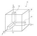
図19は、本発明の第5実施形態における力覚提示装置を概略的に示す斜視図であり、図20は、図19に示す力覚提示装置の1つの指に対応するアーム部の拡大図であり、図21は、図20に示すアーム部のジョイント部の断面図であり、図22は、図20に示すアーム部の指を挿入する力覚提示部の拡大図である。
【0132】
以下、第5実施形態における力覚提示装置2について、前述した第1実施形態との相違点を中心に説明し、同様の事項については、その説明を省略する。
第5実施形態における力覚提示装置2では、力覚発生部22として、特に、ユーザの指先に力覚を提示する複数のモータ201を用い、位置姿勢検出部(位置検出手段)23として、後述する複数のリンク203、複数のエンコーダ208、及び連結部204を用いる。
図19に示すように、第5実施形態の力覚提示装置2は、ユーザの各指先に適用する複数のアーム部200(図19では、2本のアーム部200しか示さないが、本実施形態では、ユーザの5本の指すべてに適用される。)と、ユーザの手の甲側に適用するアーム部200とを備える。
【0133】
なお、図19では、各アーム部200は、その一端がユーザの指先又は手の甲に装着され、他端がそれぞれ中空に浮いているように示されているが、本実施形態では、すべてのアーム部200は、上記他端側で1つにまとまり、その部分に制御部24、信号処理部25及び信号送受信部26が配置されている。しかしながら、本発明は、この構成に限らず、例えば、各アーム部200の他端側にそれぞれ制御部24、信号処理部25及び信号送受信部26を備えていてもよい。
各アーム部200の構造
(構成)はほぼ等しいので、ここでは、図20に示す指先に適用されるアーム部200、図21に示すそのアーム部200のジョイント部205、及び、図22に示す力覚提示部206及び連結部204を用いて、その構成を詳細に説明する。
【0134】
図20において、アーム部200は、3本のリンク203と、リンク203とリンク203とを連結する3つのジョイント(節)205と、各ジョイント部205に設けられる3つのモータ201と、各モータ201に対応してジョイント部205に設けられるクラッチ202と、ユーザの指先に装着する力覚提示部206と、力覚提示部206とリンク203とのジョイントをなす連結部204とを備える。
【0135】
なお、本実施形態では、3本のリンク203を備えるアーム部200について説明するが、本発明の力覚提示装置2は、これに限定されず、アーム部200にはリンク203がいくつ用いられてもよい。このリンク203の数は、本実施形態の力覚提示装置2を装着したユーザの指先の自由度、位置姿勢検出部23の検出能力(検出時間などの処理能力)などを考慮して、適当な数に決定するのが好ましい。
【0136】
ここで、図21を用いてジョイント部205の構造を説明する。図21に示すように、2つのリンク203を連結するジョイント部205には、モータ201と、モータ軸201aに連結されるエンコーダ208と、モータ201の所定の方向への回転を抑制(規制)するワンウェイクラッチ(移動規制手段)207と、このワンウェイクラッチ207を介してモータ軸201aに連結されるクラッチ(クラッチ機構)202とが配置される。なお、図21に示すように、1つのリンク203はモータ軸201aに連結し、もう1つのリンク203は、クラッチ202に連結されている。
【0137】
モータ201は、図20に示す方向A及びBのいずれにも回転可能であり、モータ201の回転角度を変えることにより、モータ201が配置されるジョイント部205に連結される2つのリンク203の角度を調整することができる。すなわち、2つのリンク203の一方は、モータ201の出力軸であるモータ軸201aに取り付けられており、モータ201の回転角度とジョイント部205の回転角度が一致するように構成されている。
【0138】
また、上述の情報処理装置8の衝突判定部82により、ユーザの指先が仮想空間画像内の対象物に触れた(衝突した)と判定された場合には、力覚提示装置2は、記憶部85に保存されているその対象物の物性データ及び状態量に基づいて演算された作用力(反力)を信号送受信部26を介して受信する。そして、モータ201は、その作用力データに基づいて、ユーザの指先に反力(力覚)を提示するように、通電されて駆動(回転)する。なお、このモータ201は、通電されていないときは回転するモータ軸201aが自由に回転可能なモータである。
【0139】
エンコーダ208は、上述のように、モータ201のモータ軸201aに連結されており、位置姿勢検出部23を構成する。エンコーダ208は、モータ201の回転角度、すなわち、2つのリンク203の相対的な回転角度を検出することができる。検出された2つのリンク203間の角度情報(信号)は、信号処理部25において所定の信号処理をされた後、信号送受信部26を介して情報処理装置8に送信される(図2参照)。
【0140】
クラッチ202のスリーブは、ワンウェイクラッチ207を介してモータ201のモータ軸201aに連結されている。このクラッチ202は、クラッチ202内部のコイルに通電することにより、モータ201の駆動を固定(回転不能に)するが、ワンウェイクラッチ207を介しているため、一方向への回転は自由なままである。
なお、図20において、ワンウェイクラッチ207が作動している場合、各ジョイント部205では、A方向には自由に回転可能であり、B方向には回転不可能である。以下、A方向を順方向、B方向をロック方向という。
【0141】
ワンウェイクラッチ207は、その内部に図示しない内輪と外輪を含み、その外輪は、クラッチ202のスリーブに固定あるいは回転止めされている。これにより、ワンウェイクラッチ207が順方向に回転する場合には、その内輪が回転し、逆に、ワンウェイクラッチ207がロック方向に回転する場合には、その内輪及び外輪、並びにクラッチ202のロータが一緒に回転する。
【0142】
なお、仮想空間において、対象物などに触れずにユーザがアーム部200を装着した指を移動する場合には、モータ201及びクラッチ202への通電がオフされ、ユーザはその指先を自由に移動することができる。
ここで、すべてのモータ201によって力覚発生手段が構成され、各リンク203、ジョイント部205、連結部204、及び力覚提示部206によって力覚提示部が構成される。また、エンコーダ208及び連結部204によって位置検出手段が構成される。
【0143】
図22に示すように、力覚提示部206は、図20に示すように、ユーザの指先が挿入できるように中空の筒状をしている。モータ201を駆動した場合やクラッチ202をオンしてワンウェイクラッチ207を作動した場合には、力覚提示部206は、それらで発生した作用力(力覚)をユーザの指先に提示するものである。
また、図23は、本発明の一実施形態における力覚提示部206の断面図であるが、力覚提示部206は、この図23に示すように、その内表面であってユーザの指腹が当たる部分にピン駆動による触覚提示部209を備えていてもよい。これにより、上記第1実施形態と同様の効果を得ることができる。
【0144】
図22では、図20に示した連結部204のカバーをはずしたものを示す。この連結部204は、ジンバル構造となっており、図22に示す矢印の方向に回転可能である。
また、連結部204は、図示しないポテンショメータ等の回転角度検出手段を備えており、力覚提示部206の姿勢を検出することができる。なお、連結部204として、ボールジョイントなどを用いることも可能であるが、その場合には、力覚提示部206の姿勢を検出する手段を別途設ける必要がある。
このように、本実施形態の力覚提示装置2は、情報処理装置8の指示に従って、モータ201をオン/オフし、あるいはクラッチ202を介してワンウェイクラッチ207を作動/不作動することにより、ユーザの指先に力覚を提示することができる。
【0145】
次に、第5実施形態における力覚提示装置2の動作(作用)について説明する。図24は、本発明の力覚提示処理(力覚提示方法)を示すフローチャートである。このフローチャートからも分かるように、本発明の力覚提示方法は、主に、力覚提示システム1における力覚提示装置2と情報処理装置8とのデータ送受信によって行われる。そのため、このフローチャートでは、仮想空間表示装置5の動作を省略しているが、必要に応じて説明を加える。
【0146】
使用に先立って、ユーザは、各部(各装置)の電源を入れ、力覚提示装置2を両手にそれぞれ装着し、眼鏡状の仮想空間表示装置5をかける(顔面に装着する)。すると、仮想空間表示装置5の画像表示部51a、51bに、予め情報処理装置8の記憶部85に画像データとして格納されている仮想空間画像、あるいは仮想空間表示装置5の撮像手段によって撮像された画像データから生成された仮想空間画像が表示される。
【0147】
そして、力覚提示システム1では、各装置の初期設定が行われる。この初期設定では、力覚提示装置2の各モータ201の回転角度、すなわち、アーム部200の各ジョイント部205の角度がエンコーダ208及び連結部204によって検出され、それらの検出された角度データは、信号送受信部26を介して情報処理装置8に送信される。
【0148】
情報処理装置8では、演算処理部81は、上記角度データに基づいて、力覚提示装置2を装着したユーザの各指先及び手の甲の仮想空間における位置及び姿勢を演算し、その演算結果、すなわち、仮想空間における各ポイントの座標を制御部84及び信号処理部86に出力する。
制御部84は、これらの座標から仮想空間内にユーザの手の画像を画像生成部83に生成させる。画像生成部83は、このユーザの手の画像データを現在仮想空間表示装置5に表示している仮想空間画像データと合成し、合成した画像データを信号処理部86及び信号送受信部87を介して仮想空間表示装置5に送信する。
【0149】
仮想空間表示装置5は、受信した仮想空間画像データを画像表示部51a、51bに表示する。以上によって、初期設定が終了する。
この初期設定が終了すると、力覚提示システム1は使用可能状態となる。以下、図24のフローチャートに基づいて、本実施形態の力覚提示装置2及び力覚提示システム1の動作を説明する。
【0150】
まず、力覚提示装置2では、位置姿勢検出部23は、各アーム部200の各ジョイント部205の角度を検出する。すなわち、位置姿勢検出部23は、各ジョイント部205に配置されるエンコーダ208を用いて対応する各モータ201の回転角度を検出し、連結部204の回転角度検出手段を用いて、力覚提示部206の姿勢を検出する。
そして、これらの検出データは、位置姿勢検出部23から信号処理部25に出力され、信号送受信部26を介して情報処理装置8に送信される(ステップS101)。
【0151】
信号送受信部87を介して力覚提示装置2から送信された検出データを受信すると、情報処理装置8は、制御部84を介してそれらのデータを演算処理部81に入力する。そして、演算処理部81は、これらの検出データに基づいて、ユーザの各指及び手の仮想空間内における位置及び姿勢を演算する(ステップS102)。
【0152】
すなわち、演算処理部81は、記憶部85に予め格納されているアーム部200のアーム長、すなわち、各リンク203のそれぞれのリンク長と、このアーム部200を支持している支持部(図示せず)の座標データと、上記検出データ、すなわち、各ジョイント部205のそれぞれ検出された回転角度とを用いて、順運動学的にユーザの指先の位置を演算する。演算結果は、ユーザの各指先及び手の甲の仮想空間における座標(位置情報)として表される。
その演算結果は、制御部84を介して画像生成部83に入力される。画像生成部83は、この演算結果に基づいて、仮想空間におけるユーザの手の画像を作成し、その手の画像を重ね合わせて仮想空間画像を更新する(ステップS103)。
【0153】
そして、その更新して生成された画像データは、信号処理部86及び信号送受信部87を介して仮想空間表示装置5に送信される。仮想空間表示装置5は、受信した画像データに基づいて、画像表示部51a、51bに更新した仮想空間画像を表示する。これにより、ユーザは、仮想空間表示装置5の画像表示部51a、51bによって、仮想空間画像内に表示されたユーザの手を見ることができる。
ここで、演算処理部81の演算結果が仮想空間内でユーザの指が移動していないことを示している場合、すなわち、上記検出データが前回の検出データ(ここでは、初期設定時のデータ)と同一である場合、画像生成部83は、仮想空間画像を更新することなく、ステップS104に移行してもよい。
【0154】
ステップS104において、情報処理装置8の衝突判定部(干渉判定手段)82は、演算処理部81によって得られたユーザの指先の位置情報及び記憶部85に予め記憶されている仮想空間画像内の対象物の位置情報に基づいて、ユーザの指先と仮想空間中の対象物が干渉したか否か(衝突したか否か)を判定する。そして、それらが干渉していないと判定された場合には(ステップS104においてNO)、各モータ201及び各クラッチ202の出力をオフ、すなわち、これらへの通電を止めて(ステップS105)、ステップS101に戻り同様の処理を繰り返す。なお、現時点ではモータ201又はクラッチ202への通電は行われていないので、そのままステップS101に戻り同様の処理を繰り返す。
【0155】
また、ステップS104においてユーザの指先と対象物が干渉したと判定された場合には(ステップS104においてYES)、制御部84は、その対象物の物性データ及び状態量データを記憶部85の所定の保存先から読み出し、これらのデータを演算処理部81に出力する。演算処理部81は、当該データに基づいて、対象物のユーザの指への作用力を演算する(ステップS106)。
【0156】
ステップS107において、制御部84(ここでは、判別手段)は、演算処理部81によって演算された作用力が予め設定され、記憶部85の所定の保存領域に記憶されている所定の閾値よりも大きいか否かを判別する。そして、この作用力が所定の閾値よりも大きいと判別された場合には、制御部84は、クラッチ202の動作信号(作動信号)を信号処理部86及び信号送受信部87を介して力覚提示装置2に送信する(ステップS109)。
一方、上記作用力が所定の閾値よりも小さいと判別された場合には、演算処理部81は、力覚提示装置2の各モータ201への作用力の分配比率を演算し(ステップS109)、その演算結果を適正なモータ動作信号として信号処理部86及び信号送受信部87を介して力覚提示装置2に送信する(ステップS110)。
【0157】
モータ201の動作信号又はクラッチ202の動作信号を受信した力覚提示装置2は、制御部24を介してその動作信号を力覚発生部22に入力する。そして、力覚発生部22は、その動作信号に基づいて、モータ201又はクラッチ202を通電し、モータ201の動作信号の場合には、各モータ201を駆動して作用力(力覚)を発生し、クラッチ202の動作信号の場合には、クラッチ202を駆動してワンウェイクラッチ207を作動して(ステップS111)、この力覚提示処理を終了する。
これにより、ユーザは、力覚提示部206を介してモータ201で発生した力覚を提示され、あるいは、ワンウェイクラッチ207の作動によりユーザの指先の所定の方向への移動を規制される。
【0158】
なお、この図24のフローチャートに示す力覚提示処理におけるステップS101の各ジョイント部205の検出ステップは、情報処理装置8の演算処理部81の演算処理能力に基づいて、所定の時間間隔で、例えば、1〜2秒毎に実行される。この検出ステップの検出頻度は、大きければ大きいほど、すなわち、時間間隔が短ければ短いほど、仮想空間領域におけるユーザへの力覚提示が自然に近くなるので、その検出頻度は、上記演算処理部81の演算処理能力に応じて適宜決定されるべきである。
【0159】
次いで、図25のフローチャートを参照して、本発明のコントラスト提示処理について説明する。図25は、本発明のコントラスト提示処理(コントラスト提示方法)を示すフローチャートである。このコントラスト提示処理は、好ましくは、ユーザが本発明の力覚提示装置2を装着したとき、すなわち、本発明の力覚提示装置2の使用開始時に行われる。なお、このコントラスト提示処理は、ユーザの指に作用する力覚のキャリブレーション、すなわち、力覚提示装置2のキャリブレーションに相当する処理である。
【0160】
なお、上記力覚提示処理のフローチャート(図24)と同様に、このフローチャートでも、仮想空間表示装置5の動作を省略しているが、必要に応じて適宜説明を加える。また、説明が前後するが、上述の初期設定が終了し、本発明のコントラスト提示処理を実行した後、通常の使用時には、上記力覚提示処理が常時実行されている。
【0161】
まず、ユーザに力覚のコントラストを提示するために、情報処理装置8の画像生成部83において、記憶部85に予め格納されている画像データに基づいて、仮想空間画像中に所定の対象物の画像が生成される(ステップS201)。そして、この生成された画像は、信号処理部86及び信号送受信部87を介して仮想空間表示装置5に送信される。仮想空間表示装置5では、その画像データは、画像表示部51a、51bに表示される。
【0162】
仮想空間画像が仮想空間表示装置5に表示された状態において、力覚提示装置2では、位置姿勢検出部23は、各アーム部200の各ジョイント部205の角度を検出する。すなわち、位置姿勢検出部23は、各ジョイント部205に配置されるエンコーダ208を用いて対応する各モータ201の回転角度を検出し、連結部204の回転角度検出手段を用いて、力覚提示部206の姿勢を検出する。
そして、これらの検出データは、位置姿勢検出部23から信号処理部25に出力され、信号送受信部26を介して情報処理装置8に送信される(ステップS202)。
【0163】
信号送受信部87を介して力覚提示装置2から送信された検出データを受信すると、情報処理装置8は、制御部84を介してそれらのデータを演算処理部81に入力する。そして、演算処理部81は、これらの検出データに基づいて、ユーザの各指及び手の仮想空間内における位置及び姿勢を演算する(ステップS203)。
【0164】
すなわち、演算処理部81は、記憶部85に予め格納されているアーム部200のアーム長、すなわち、各リンク203のそれぞれのリンク長と、このアーム部200を支持している支持部(図示せず)の座標データと、上記検出データ、すなわち、各ジョイント部205のそれぞれ検出された回転角度とを用いて、順運動学的にユーザの指先の位置を演算する。演算結果は、ユーザの各指先及び手の甲の仮想空間における座標(位置情報)として表される。
【0165】
その演算結果は、制御部84を介して画像生成部83に入力される。画像生成部83は、この演算結果に基づいて、仮想空間におけるユーザの手の画像を作成し、その手の画像を重ね合わせて仮想空間画像を更新する(ステップS204)。なお、このコントラスト提示処理では、開始時に、例えば、上記で表示された所定の対象物を適当な力の強さで押すように、仮想空間表示装置5に適当なメッセージを表示するのが好ましい。
【0166】
そして、その更新して生成された画像データは、信号処理部86及び信号送受信部87を介して仮想空間表示装置5に送信される。仮想空間表示装置5は、受信した画像データに基づいて、画像表示部51a、51bに更新した仮想空間画像を表示する。これにより、ユーザは、仮想空間表示装置5の画像表示部51a、51bによって、仮想空間画像内に表示されたユーザの手を見ることができる。
【0167】
ステップS205において、情報処理装置8の衝突判定部82は、演算処理部81によって得られたユーザの指先の位置情報及び記憶部85に予め記憶されている仮想空間画像内の当該所定の対象物の位置情報に基づいて、ユーザの指先と仮想空間中の対象物が干渉したか否か(衝突したか否か)を判定する。そして、それらが干渉していないと判定された場合には(ステップS205においてNO)、各モータ201の出力をオフ、すなわち、通電を止めて(ステップS206)、ステップS202に戻り同様の処理を繰り返す。なお、上記のようにユーザに対して対象物と干渉するように表示などをしている場合には、ユーザはこの対象物を触ろうと仮想空間中で手及び指を移動するので、このような処理が行われることは稀であろう。
【0168】
また、ステップS205においてユーザの指先と対象物が干渉したと判定された場合には(ステップS205においてYES)、制御部84は、その対象物の物性データ及び状態量データを記憶部85の所定の保存先から読み出し、これらのデータを演算処理部81に出力する。演算処理部81は、当該データに基づいて、対象物のユーザの指への最初の作用力を演算する(ステップS207)。このコントラスト提示処理では、ユーザ側が主体となって所定の対象物を押す動作をしているので、仮想空間中における所定の対象物の表示位置にユーザの指先を保持(固定)するために、その作用力と反対方向への反力(相互作用)を力覚発生部22である各モータ201が駆動して発生している。そのため、演算処理部81は、ここでは、各モータ201を駆動するための入力信号(制御信号)を用いて(あるいは、別のセンサ(図示せず)によりモータの出力をモニタして)、ユーザが対象物を押している作用力を演算することとなる。
【0169】
そして、制御部84は、ユーザの指先の位置が所定の位置から動かないように、力覚提示装置2の力覚発生部22である各モータ201をユーザの押す作用力に追従して駆動制御する(ステップS208、S209)。なお、この場合でも、ユーザの作用力は、演算処理部81の演算結果に基づいて、各モータ201に分配される。
【0170】
ステップS210において、情報処理装置8の制御部84は、ユーザが対象物を押す作用力が第1の閾値を超えているか否かを判定する。第1の閾値を超えていないと判定された場合には、ステップS207に戻り、同様の処理(作用力を演算し、各モータ201に分配する処理)を繰り返す。
ステップS210において上記ユーザの作用力が第1の閾値を超えていると判定された場合には、制御部84は、記憶部85に予め保存されている第2の閾値に対応する、各モータ201の動作信号(制御信号)を、信号処理部86及び信号送受信部87を介して力覚提示装置2に送信する(ステップS211)。
この各モータ201の動作信号を受信した力覚提示装置2は、この信号に基づいて、各モータ201の出力を変更し(ステップS212)、このコントラスト提示処理を終了する。
【0171】
なお、第1及び第2の閾値は、情報処理装置8(すなわち、力覚提示システム1)に予め設定されていてもよく、あるいは、力覚提示システム1(力覚提示装置2)を利用するユーザによって適宜変更可能なように構成されていてもよい。第1の閾値としては、ユーザが十分に所定の対象物を押していると感じる程度の大きさであるとともに、力覚提示装置2にとって過負荷とならないような大きさであることが好ましく、例えば、5kg重(50N(ニュートン))程度である。
【0172】
また、第2の閾値は、第1の閾値に対応して、ユーザ、すなわち、人間がコントラストを十分に感じられるように、小さい値である方がよく、好ましくは、各モータ201によって発生する作用力が概ね0に相当する値、すなわち、モータ201への通電を止めたときの作用力(負荷)の値(このとき、ユーザの指先は自由な移動が可能である)である。
このように、第1の閾値と第2の閾値が十分にずれて(離れて)いることにより、ユーザへのコントラストはよりよく提示される。
【0173】
次いで、図26のフローチャート及び図27〜図29の概略図を参照して、本発明の画像補正方法(画像補正処理)を説明する。なお、力覚提示装置2の構成は、本第5実施形態のもので代表して説明する。図26は、本発明の画像補正処理を示すフローチャートであり、図27は、力覚提示手段を装着した2本の指で紙を掴む場合の概念図(補正前)、図28は、力覚提示手段を装着した2本の指を接触させた場合の概念図(補正後)、図29は、本発明の画像補正処理で人差し指を補正した場合の概念図(補正前後)である。
【0174】
この画像補正処理も、上記コントラスト提示処理と同様に、好ましくは、ユーザが本発明の力覚提示装置2を装着したとき、すなわち、本発明の力覚提示装置2の使用開始時に行われる(対応するアプリケーションプログラムが実行される)。なお、この画像補正処理は、ユーザの指を含む仮想空間画像のキャリブレーション、すなわち、力覚提示システム1のキャリブレーションに相当する処理である。
【0175】
なお、上記力覚提示処理のフローチャート(図24)及びコントラスト提示処理(図25)と同様に、このフローチャートでも、仮想空間表示装置5の動作を省略しているが、必要に応じて適宜説明を加える。また、説明が前後するが、上述の初期設定が終了し、本発明のコントラスト提示処理を実行した後、通常の使用時には、上記力覚提示処理が常時実行されている。
【0176】
まず、ユーザは、情報処理装置8の指示によって所定のメッセージが表示された仮想空間表示装置5を確認し(ステップでは示さず)、力覚提示装置2を装着した手を基準位置に移動する。ここで、基準姿勢とは、例えば、指のすべての関節を伸ばして掌を開いた状態のように、少なくとも親指と処理対象の指(このフローチャートの説明では、人差し指)の関節が伸びた状態の姿勢をいう。
【0177】
そして、この基準姿勢の状態において、位置姿勢検出部23は、仮想空間におけるユーザの指先の位置を検出するために、各アーム部200の各ジョイント部205の角度を検出する。すなわち、位置姿勢検出部23は、各ジョイント部205に配置されるエンコーダ208を用いて対応する各モータ201の回転角度を検出し、連結部204の回転角度検出手段を用いて、力覚提示部206の位置及び姿勢、すなわち、ユーザの手及び指の位置及び姿勢を検出する。そして、制御部24は、これらの検出データ(角度データ)を信号処理部25及び信号送受信部26を介して情報処理装置8に送信する(ステップS301)。
【0178】
信号送受信部87を介して力覚提示装置2から送信された検出データを受信すると、情報処理装置8は、制御部84を介してそれらのデータを演算処理部81に入力する。そして、演算処理部81は、これらの検出データに基づいて、ユーザの各指及び手の仮想空間内における位置及び姿勢を演算する(ステップS302)。そして、制御部84は、演算結果及び各ジョイント部の関節角度θi(i=1,2,・・・)を記憶部85の所定の保存領域に格納する。
【0179】
なお、ユーザの各指及び手の仮想空間内における位置及び姿勢を演算する方法は、各エンコーダの出力から得られる関節角度及びリンク203のリンク長などを用いて、力覚提示システム1(又は力覚提示装置2)における所定の基準位置から順運動学的に指先及び手の甲の位置・姿勢を演算し、この演算結果から得られた指先及び手の甲の位置・姿勢に基づいて、指の各関節をリンクとして近似表現したデータを用いて、指先の位置から逆運動学的にユーザの手の位置検出を行っていない部分の形状(例えば、指の各関節角度など)を演算するというものである。このように、順運動学的演算だけでなく、逆運動学的演算を行うことにより、仮想空間におけるユーザの手及び指の位置・姿勢を正確に検出することができる。
【0180】
上述の各データの格納が終わると、同様に、ユーザは、情報処理装置8の指示によって所定のメッセージが表示された仮想空間表示装置5を確認し(ステップでは示さず)、力覚提示装置2を装着した手の人差し指と親指の2本で何もない状態でものを摘む動作をする。
【0181】
そして、この状態において、位置姿勢検出部23は、仮想空間におけるユーザの指先の位置を検出するために、各アーム部200の各ジョイント部205の角度を検出する。すなわち、位置姿勢検出部23は、各ジョイント部205に配置されるエンコーダ208を用いて対応する各モータ201の回転角度を検出し、連結部204の回転角度検出手段を用いて、力覚提示部206の位置及び姿勢、すなわち、ユーザの手及び指の位置及び姿勢を検出する。そして、制御部24は、これらの検出データ(角度データ)を信号処理部25及び信号送受信部26を介して情報処理装置8に送信する(ステップS303)。
【0182】
信号送受信部87を介して力覚提示装置2から送信された検出データを受信すると、情報処理装置8は、制御部84を介してそれらのデータを演算処理部81に入力する。そして、演算処理部81は、これらの検出データに基づいて、上記ステップS302の場合と同様に、ユーザの各指及び手の仮想空間内における位置及び姿勢を演算する(ステップS304)。そして、制御部84は、演算結果及び各ジョイント部の関節角度φi(i=1,2,・・・)を記憶部85の所定の保存領域に格納する。
【0183】
上述の各データの格納が終わると、演算処理部81の演算結果に基づいて、画像生成部83は、ユーザの手を取り込んだ状態における仮想空間画像を生成する(ステップS305)。ここで、ユーザが力覚提示装置2を装着した2本の指で実際に摘んでいる(2本の指が接触している)状態を図27に示す。実空間においては、図27(A)に示すように、ユーザの2本の指先は、力覚提示部206の厚みを介して接触(干渉)している。一方、仮想空間画像においては、図27(B)に示すように、仮想空間表示装置5は、力覚提示部206に厚みがあるために、2本の指はぴったりと接触しているように表示することができず、仮想空間では、対象物(図27では、紙などの薄状物)は、2本の指先の間に接触していないように表示される。なお、このユーザの指が摘む動作をしている状態の各指先の位置を実摘み位置という。
【0184】
この状態において、画像生成部83は、図27(B)のような状態から図28(B)のような状態になるように、仮想空間画像を変更(補正)して生成するとともに(ステップS306)、図28(B)に示すような2本の指先位置を特定し、制御部84を介してその位置情報(座標データ)を演算処理部81に出力する。なお、このユーザの2本の指が接触(干渉)している状態の各指先の位置を仮想摘み位置という。
【0185】
そして、演算処理部81は、各指先の位置が上記補正によってずれた際の、実摘み位置から仮想摘み位置へのずれ量に基づいて、各ジョイント部205の関節角度のずれ量を演算する(ステップS307)。なお、このずれ量の演算は、基準となる指(本実施形態では、親指)に対して一方の指(本実施形態では、人差し指)についてのみ行われる。このように、2本の指先の一方の指についてのみ、仮想空間画像を補正するための演算を行うことによって、本発明では演算を容易に実行することができる。
【0186】
そして、制御部84は、上記ずれ量演算によって得られた各ジョイント部205の関節角度のずれ量αi(i=1,2,・・・)を記憶部85の所定の保存領域に格納する。以下、上記θi、φi、及びαiに基づいて、制御部84は、仮想空間画像を補正するための変換則を決定する(ステップS308)。この変換則に用いられる変換方法は、いろいろなものが考えられるが、ここでは、代表的な2つの変換方法を示す。
【0187】
まず、第1の変換方法は、上記ずれ量に基づいて、基準姿勢のときの親指以外の指(本実施形態では、人差し指)の指先位置から仮想摘み位置までの間において、力覚提示装置2のアーム部200の各ジョイント部205の関節角度を比例拡大するものである。すなわち、本発明の力覚提示装置2をユーザが操作している間、一定周期(例えば、1,2秒)で対応するアーム部200の各ジョイント部205の関節角度がエンコーダ208によって検出され、演算処理部81は、その検出結果、すなわち、各ジョイント部の関節角度βi(i=1,2,・・・)に対して、上述の検出結果から定まる定数:
Ki=(φi−θi+αi)/(φi−θi) (1)
を用いて、換算(変換)された各ジョイント部205の関節角度:
βnewi=Ki・(βi−θi)+θi (2)
を演算する。そして、このようにして得られた各ジョイント部205の関節角度に基づいて、情報処理装置8の画像生成部83は、仮想空間におけるユーザの指を取り込んで、仮想空間画像を生成(更新)する。
【0188】
次に、第2の変換方法は、上述のようにエンコーダ208によって検出され、記憶部85に格納された各ジョイント部205の関節角度のずれ量αiの値をそのまま用いて、この値を各モータ201の回転角度のオフセット値として用いるものである。具体的には、上述の力覚提示処理(図24参照)のステップS101に示すように、力覚提示装置2では、装置の駆動中(操作中)予め設定された一定周期で、位置姿勢検出部23によって各ジョイント部205の回転角度(関節角度)が検出されている。検出された回転角度と関節角度のずれ量αiとを用いて、演算処理部81は、換算(変換)された各ジョイント部205の関節角度:
βnewi=βi+αi (3)
を演算する。そして、このようにして得られた各ジョイント部205の関節角度に基づいて、情報処理装置8の画像生成部83は、仮想空間におけるユーザの指を取り込んで、仮想空間画像を生成(更新)する。
【0189】
ステップS308において決定された変換則は、情報処理装置8の記憶部85の所定の保存領域に格納(保存)されて(ステップS309)、この画像補正処理を終了する。そして、この画像補正処理によるキャリブレーションを終了すると、力覚提示装置2は、通常モードである力覚提示処理(図24参照)を駆動中は実行する。このとき、各ジョイント部205の関節角度を検出し(ステップS101)、それに基づいて、ユーザの各指先位置を演算した後(ステップS102)、この演算結果及び上記ステップS309において格納された変換則に基づいて、画像生成部83は、仮想空間画像を更新して生成する。
【0190】
例えば、上記第2の変換則を用いた場合、図29に示すように、ユーザの親指の位置に対して、人差し指の位置が力覚提示部206の厚さに対応したずれ量(距離)だけ近づいた状態で、ユーザの手は、仮想空間画像に取り込まれて仮想空間表示装置5に表示される。なお、この図29(B)に示すように、仮想空間におけるユーザの指先の画像を補正する場合には、親指を固定し、人差し指の中手指節関節の回転角度(曲げ角度)で調整するのが好ましい。
なお、本実施形態では、具体的な画像の変換方法として、代表的な2つの変換方法を示したが、本発明はこれに限定されず、従来から知られる(公知の)いずれの変換方法が用いられてもよい。また、本発明では、予め計測された力覚提示部206の厚みに基づいて、上記関節角度のずれ量を演算してもよい。
【0191】
以上のように、本発明における力覚提示装置2、力覚提示システム及び画像補正方法は、ユーザの手(指先)が基準姿勢にある場合における各ジョイント部205の関節角度と、ユーザの指先が実摘み位置にある場合における各ジョイント部205の関節角度とをエンコーダ208を用いて検出するとともに、実摘み位置から演算された仮想摘み位置における各ジョイント部205の関節角度を演算し、検出結果及び演算結果に基づいて、実摘み位置と仮想摘み位置の間における各ジョイント部205の関節角度のずれ量を演算し、その演算されたずれ量に基づいて変換則を決定するように構成される。そして、本発明の画像補正方法によりユーザ毎にキャリブレーションを取った後、力覚提示装置2及び力覚提示システム1は、通常の力覚提示方法(例えば、図24のフローチャートに示す力覚提示処理)によって、本発明の力覚提示装置2を装着しているユーザの指先に力覚を提示する。
【0192】
したがって、本発明の力覚提示装置2、力覚提示システム1及び画像補正方法によって、実空間では力覚提示部206の厚みが存在するために到達不可能(表現不可能)であった力覚が提示されている部位(本実施形態では、ユーザの指先)の位置や姿勢まで仮想空間において表現することができる。それにより、仮想空間において、ユーザの位置・姿勢などの自然な状態を表現することができる。
【0193】
また、本発明の力覚提示装置2及び力覚提示システム1では、本発明の画像補正方法(画像補正処理)において得られた関節角度のずれ量をそれ以後の力覚提示処理などにおいて適用する際、仮想空間画像におけるユーザの指先の画像の補正は、主に親指以外の各指の中手指節関節の回転角度によって調整することとしたので、本発明の仮想空間画像は、簡便な方法で(高度な画像補正処理を必要とせず)、自然な表現が可能となる。
【0194】
なお、第5実施形態では、ユーザの親指と人差し指の各指先について、本発明の画像補正方法(画像補正処理)を適用した場合について説明したが、本発明は、この場合に限らず、例えば、親指と中指、あるいは親指と薬指のように、掴む動作をした際に接触するであろう任意の2本の指の指先に対して適用することができる。
【0195】
また、第5実施形態では、本発明の力覚提示装置2の力覚提示部206を装着したユーザの2本の指先におけるキャリブレーションについて説明したが、本発明の画像補正方法は、このような場合(状態)のみに限定されず、例えば、仮想空間中の対象物とユーザの各指の指先との干渉(接触)においても適用可能である。この場合、その対象物に接触している各指先に本発明が適用され、仮想空間画像においてユーザの指先の位置を補正した画像が、情報処理装置8の画像生成部83によって生成されることとなる。
なお、本発明では、前記各実施形態の任意の2以上の構成(特徴)を適宜組み合わせてもよい。すなわち、本発明では、第5実施形態の力覚提示装置2に他の実施形態の触覚発生部21などを組み合わせてもよい。
【0196】
また、本発明の力覚提示システム1は、情報処理装置8の画像生成部83によって仮想空間画像を生成し、その仮想空間画像を仮想空間表示装置5に表示するように構成されているが、本発明は仮想空間において適用する場合に限らず、例えば、仮想空間画像を表示せずに、力覚提示装置2と情報処理装置8のみによって構成されてもよい。また、本発明の力覚提示システム1は、上記各装置を一体的に1つの装置、すなわち、力覚提示装置のみとして構成してもよい。
以上、本発明の力覚提示装置及び力覚提示システムの構成を、図示の実施形態に基づいて説明したが、本発明はこれに限定されるものではなく、各部の構成は、同様の機能を有する任意の構成のものに置換することができる。
【図面の簡単な説明】
【図1】本発明の力覚提示装置及びその力覚提示装置を有する力覚提示システムの第1実施形態の構成例を示す概念図である。
【図2】図1に示すリアルグローブの回路構成例を示すブロック図である。
【図3】図1に示すリアルグローブの外観構成例を示す外観図(一部図示を省略)である。
【図4】図1に示すリアルグローブの触覚発生部の構成例を示す縦断面図である。
【図5】図1に示すリアルグローブの力覚発生部の構成例を示す外観図である。
【図6】図1に示すリアルグローブの力覚発生部の構成例を示す外観図である。
【図7】図1に示すリアルグローブの位置姿勢検出部の構成例を示すブロック図である。
【図8】図1に示す仮想空間表示装置の外観構成例を示す斜視図である。
【図9】図1に示す仮想空間表示装置の回路構成例を示すブロック図である。
【図10】図1に示す仮想空間表示装置の凹凸入力部の構成例を示す図(ブロック図、模式図)である。
【図11】図1に示す仮想空間表示装置の画像表示部の構成例を示す図(ブロック図、模式図)である。
【図12】図1に示す仮想空間表示装置の視線検出部の構成例を示す図(ブロック図、模式図)である。
【図13】図1に示す情報処理装置の回路構成例を示すブロック図である。
【図14】第2実施形態における力覚提示装置の触覚発生部の構成例を示す縦断面図である。
【図15】第3実施形態における力覚提示装置のリアルグローブの外観構成例を示す外観図(一部図示を省略)である。
【図16】第4実施形態における力覚提示装置の位置姿勢検出部の構成例を示すブロック図である。
【図17】第4実施形態における力覚提示装置の位置姿勢検出部の構成例を示す外観図(一部図示を省略)である。
【図18】図17に示す位置姿勢検出部のZ方向検出センサの構成例を示す外観図である。
【図19】第5実施形態における力覚提示装置を概略的に示す斜視図である。
【図20】図19に示す力覚提示装置の1つの指に対応するアーム部の拡大図である。
【図21】図20に示すアーム部のジョイント部の断面図である。
【図22】図20に示すアーム部の指を挿入する力覚提示部の拡大図である。
【図23】本発明の一実施形態における図20に示す力覚提示部の断面図である。
【図24】本発明の力覚提示処理を示すフローチャートである。
【図25】本発明のコントラスト提示処理を示すフローチャートである。
【図26】本発明の画像補正処理を示すフローチャートである。
【図27】力覚提示手段を装着した2本の指で紙を掴む場合の概念図(補正前)である。
【図28】力覚提示手段を装着した2本の指を接触させた場合の概念図(補正後)である。
【図29】本発明の画像補正処理で人差し指を補正した場合の概念図(補正前後)である。
【符号の説明】
1……力覚提示システム、2……力覚提示装置、2a……手袋、2b……フレームホルダ、2c……フレームカバー、2d……腕固定部、20……リアルグローブ、20a……筒状部、200……アーム部、201……モータ、201a……モータ軸、202……クラッチ、203……リンク、204……連結部、205……ジョイント部、206……力覚提示部、207……ワンウェイクラッチ、208……エンコーダ、209……ピン駆動による触覚提示部、21……触覚発生部、21a……開口、21d……腕固定部本体、210……単位触覚発生部、211……動力発生部、211a……モータ、212……アクチュエータワイヤ、212a……束、213……ワイヤ保持部、214……触覚提示ピン、214a……接触板、214b……支持部、215……触覚提示ピン支持部、216……触覚提示部、216a……第1の板片、216b……第2の板片、216c……接触部、217……ガイド部、218……押え板、22……力覚発生部、22d……エアー注入部、221……フレーム、222……リンクモータ、23……位置姿勢検出部、23d……蓋体、231……X方向検出コイル、232……Y方向検出コイル、233……Z方向検出コイル、24……制御部、25……信号処理部、251……増幅部、252……A/D変換部、26……信号送受信部、27……遊び吸収部、28……手首固定部、29……ねじれ吸収部、291……帯状部、292……開口、30……電力供給部、5……仮想空間表示装置、51a、51b……画像表示部、511……レンズ、512……レンズ移動機構、513……ステッピングモータ、514……モータ制御部、515……液晶表示パネル、516……液晶駆動部、517……バックライト、518……バックライト制御部、519……トランジスタ、52a、52b……視線検出部、521……ハーフミラー、522……フィルタ、523……レンズ、524……CCD、525……CCD制御部、526……CCD出力増幅部、527……LED、528……LED制御部、529……トランジスタ、53a、53b……凹凸入力部、531……レンズ、532……CCD、533……CCD制御部、534……CCD出力増幅部、54……制御部、55……信号送受信部、56……位置姿勢検出部、57……装着部、58……信号処理部、59……三次元加速度センサ、60……ケーシング、61……X方向検出センサ、62……Y方向検出センサ、63……Z方向検出センサ、64……エリンバー、65……振動用圧電素子、66……検出用圧電素子、67、68……ワイヤ、69……交流電源、8……情報処理装置、81……演算処理部、82……衝突判定部、83……画像生成部、84……制御部、85……記憶部、86……信号処理部、87……信号送受信部、88……磁界発生部、9……基地局[0001]
TECHNICAL FIELD OF THE INVENTION
The present invention relates to a haptic device and an image correcting method in the haptic device, and more particularly, to a haptic device used in a virtual space (virtual reality) system and an image correcting method in the haptic device. About.
[0002]
[Prior art]
A conventional force sense presentation device uses an actuator such as a motor and a clutch (for example, see Patent Literature 1), a device that uses a fluid such as air or liquid (for example, see Patent Literature 2), or a wire. There are motors that take up the motor (for example, see Patent Literature 3), and they express the interaction between the operator and the object using elasticity and viscosity.
[0003]
[Patent Document 1]
JP-A-2000-246677
[Patent Document 2]
JP-A-2000-99240
[Patent Document 3]
JP-A-6-324622
[0004]
[Problems to be solved by the invention]
However, as in the conventional force sense presentation device described in
[0005]
That is, since such a conventional haptic device does not generate and display a virtual space image in consideration of the thickness of the haptic device, the target in the virtual space that is thinner than the thickness of the haptic device. If an attempt is made to grasp (pluck) an object, for example, paper, the virtual space image cannot be displayed properly using the actually detected position information of the fingertip (ie, grasping the paper with the fingertip) Cannot be displayed), and the interaction between the site and the object cannot be appropriately presented (that is, it is determined (determined) that the site and the position of the object interfere with each other). Therefore, a force sense suitable for the target object cannot be presented).
[0006]
An object of the present invention is to correct a virtual space image according to a virtual space image by correcting the virtual space image in consideration of the thickness of the region where the force sense displayed in the virtual space is presented. The present invention is to provide a force sense presentation device and an image correction method that can be displayed on a computer.
[0007]
[Means for Solving the Problems]
In order to solve the above-described problems, in one embodiment of the present invention, a haptic device according to the present invention includes:
Image generation means for generating a virtual space image;
Display means for displaying the virtual space image generated by the image generation means,
Force sense generating means for generating a sense of force given to the user's finger according to the virtual space image,
A force sense presentation unit attached to the finger and presenting the force sense generated by the force sense generation unit to the finger,
When the fingertip on which the force sense presentation means is attached is brought into contact with an object, the force sense presentation means is generated by the image generation means so as to remove the thickness of the force sense presentation means in a virtual space image displayed by the display means. Image correction means for correcting the virtual space image,
It is characterized by having.
[0008]
According to the force sense presentation device of the present invention, the virtual space image generated by the image generation means is used when the force sense generated by the force sense generation means is presented to the user's finger via the force sense presentation means. The thickness of the haptic presentation means attached to the user's fingertip is removed so that the display means displays the object in the virtual space such that the fingertip of the user wearing the haptic presentation means is in contact with the object in the virtual space. Is corrected as follows.
[0009]
In addition, the haptic device according to another embodiment of the present invention,
Image generation means for generating a virtual space image;
Display means for displaying the virtual space image generated by the image generation means,
Force sense generating means for generating a sense of force given to the user's finger according to the virtual space image,
A force sense presentation unit attached to the finger and presenting the force sense generated by the force sense generation unit to the finger,
When the two fingertips on which the haptic presentation unit is attached are brought into contact, the haptic presentation unit is generated by the image generation unit so as to remove the thickness of the haptic presentation unit in the virtual space image displayed by the display unit. Image correction means for correcting the virtual space image,
It is characterized by having.
[0010]
According to this force sense presentation device, unlike the above-described case where the user's fingertip and the target in the virtual space contact (interference), the same operation is performed when the user's two fingertips contact (interference). To play.
Therefore, with the haptic device of the present invention, in a virtual space, a natural state such as the position / posture of the user can be obtained without being affected by the thickness (bias) of the haptic device attached to the user's fingertip or the like. Can be expressed.
[0011]
Here, the display unit displays an instruction to the user, such as a message, so that the virtual space image is corrected by the image correction unit when the user first wears the force sense presentation unit. Alternatively, the haptic device of the present invention may be configured to give an instruction to the user by voice. Preferably, the force sense presented by the force sense presentation means corresponds to a reaction force from the target in the virtual space image.
[0012]
Preferably, in consideration of interference in a real space, preferably, the two fingers are one of the user's thumb and a finger other than the thumb, and the virtual space image is corrected. One of the two fingertips is one of the fingers other than the thumb.
Here, preferably, the apparatus further comprises position detecting means for detecting a position in a virtual space of the finger on which the force sense presenting means is mounted, and wherein the image correcting means is configured to detect the positions of the two fingers detected by the position detecting means. The thickness of the force sense presentation means is removed based on the fingertip position information.
[0013]
In this case, the position detection unit detects a position of the fingertip in the virtual space in a state where the two fingertips of the user wearing the force sense presentation unit are in the reference posture, and the image correction unit includes: Relative positional information between the position where the two fingertips are brought into contact and the position of the two fingertips in the reference posture, and the two positions when the thickness of the force sense presentation unit is removed. Based on relative position information between the position of a fingertip and the position of the two fingertips in the reference posture, the position of one of the two fingertips in the virtual space is the position of the reference posture and the position of the reference posture. The virtual space image may be corrected so as to be a position proportionally enlarged from the position of the other fingertip between the contact positions when the thickness of the force sense presentation unit is removed. Here, preferably, the reference posture is a posture when the user spreads his hand.
[0014]
In one embodiment of the present invention, the image correction unit may be configured to correct the virtual space image using the thickness of the force sense presentation unit as an offset.
In another embodiment of the present invention, the haptic presentation unit includes an arm unit including a plurality of links and a plurality of nodes connecting the links, and a haptic presentation unit attached to the finger. And a connecting unit that connects the arm unit and the haptic presentation unit, and the haptic generating unit may be configured by a plurality of actuators that are motors respectively arranged in the plurality of nodes.
[0015]
In such a case, the position detecting means detects the position of the fingertip by detecting the rotation angle of each of the plurality of motors by a plurality of encoders connected to output shafts of the plurality of motors. May be configured. The force sense presentation device according to the present invention is configured such that, based on the position information of the finger in the virtual space detected by the position detection unit and the position information of the object in the virtual space set in advance, the finger is Interference determination means for determining whether or not interference with the object,
When the interference determination unit determines that the finger and the object interfere with each other, an operation for calculating an acting force to be presented to the finger based on the physical property data and the state quantity data of the object. Means are further provided,
The force sensation generating means may be configured to generate a force sensation to be presented to the user's fingertip by the force sensation providing means based on a calculation result of the calculation means.
[0016]
Further, the force sense presentation device of the present invention, a movement regulation means for regulating movement of the force sense presentation means in a predetermined one direction,
A clutch mechanism for switching operation / non-operation of the movement restricting means;
Determining means for determining whether the acting force calculated by the calculating means exceeds the predetermined threshold value, and
The clutch mechanism may be configured to activate or deactivate the movement restricting means by switching on / off based on a result of the determination by the determining means.
[0017]
Preferably, the haptic device according to the present invention further includes storage means for storing at least position information data of the object, the physical property data, and the state quantity data. Further preferably, the image generation means updates and generates the virtual space image at predetermined time intervals based on position information of the finger in the virtual space detected by the position detection means, and generates the display means. Continuously displays the virtual space image updated with the movement of the finger. The display means may be used by being worn on the face.
[0018]
In order to solve the above problem, in another aspect of the present invention, an image correction method of the present invention generates a virtual space image, displays the generated virtual space image, and responds to the virtual space image. An image correction method for a force sense presentation device that generates a force sense to be given to a user's finger and presents the force sense to the finger by a force sense presentation unit attached to the finger,
In the virtual space image displayed when the fingertip of the user wearing the haptic presentation unit is brought into contact with the object, the thickness of the haptic presentation unit is removed and the fingertip contacts the object. The virtual space image is corrected.
Alternatively, in a virtual space image displayed when two fingertips of the user wearing the haptic presentation unit are brought into contact with each other, the thickness of the haptic presentation unit is removed and the two fingertips come into contact with each other. As described above, the virtual space image is corrected.
[0019]
According to the image correction method of the present invention, it is possible to express a natural state such as the position and posture of a user in a virtual space without being affected by the thickness of a force sense presentation unit attached to a user's fingertip or the like. it can.
Also preferably, the image correction method of the present invention detects a position of the user's finger wearing the haptic presentation unit in a virtual space, and provides the haptic presentation based on the detected position information of the fingertip. The virtual space image is corrected so as to remove the thickness of the part. Thereby, the position of the user's fingertip in the virtual space can be accurately detected, and the thickness of the force sense presentation unit can be removed based on the position. It is possible to express a natural state such as the position and posture of the user without being affected by the thickness of the force sense presentation unit.
[0020]
In this case, the position of the fingertip in the virtual space is detected in a state in which the two fingertips of the user wearing the force sense presentation unit are in the reference posture, and the fingertip in a state in which the two fingertips are in contact with each other The position of the two fingertips is calculated, and the position of the two fingertips in the virtual space when the thickness of the force sense presentation unit is removed is calculated based on the position information in the contact state of the two fingertips, One fingertip of the two fingertips in the virtual space based on relative position information between the position of the fingertip in the posture and the position of the fingertip in the contact state or the calculated position of the fingertip The position of the reference posture, between the contact position when the thickness of the force sense presentation unit is removed from the position of the other fingertip, so as to be a position proportionally enlarged from the position of the other fingertip, Virtual space image may be corrected.
Further, instead of the above-described image correction method, the position of one of the two fingertips displayed on the virtual space image may be corrected with the thickness of the force sense presentation unit as an offset.
[0021]
BEST MODE FOR CARRYING OUT THE INVENTION
Hereinafter, a haptic device and an image correction method according to the present invention will be described in detail based on preferred embodiments shown in the accompanying drawings. This embodiment is given as an example, and the present invention should not be construed as being limited thereto.
FIG. 1 is a conceptual diagram showing a configuration example of a first embodiment of a haptic device according to the present invention and a haptic system including the haptic device. FIG. 2 is a real glove (force haptic device) shown in FIG. FIG. 3 is a block diagram illustrating a circuit configuration example of (device). FIG. 3 is an external view (partially omitted) of an external configuration example of the real glove shown in FIG.
[0022]
As shown in FIG. 1, the haptic
[0023]
The
[0024]
The force
[0025]
The
The base station 9 includes various devices that provide information on a virtual space image, such as various server computers connected to the Internet and a mobile phone base station that performs wireless communication with a mobile phone terminal.
[0026]
In the present embodiment, each
Further, the
[0027]
Further, the
Here, in the present embodiment, the force
[0028]
In the present invention, the force
In addition, in the present invention, the force
[0029]
As shown in FIG. 2, the
Further, as shown in FIG. 3, the entire shape of the
[0030]
The user can easily and surely attach and detach the
Further, since the
The
[0031]
The
When the user wears the
[0032]
The
When the user wears the
Further, the
[0033]
The
When the user wears the
[0034]
The
The
[0035]
When the user wears the
As described above, the torsion of the
[0036]
In addition, the number of the band-shaped
Further,
These
[0037]
The
By arranging the
[0038]
When the user wears the
FIG. 4 is a vertical cross-sectional view illustrating a configuration example of the tactile
[0039]
As shown in FIG. 4A, the
The
[0040]
The
As shown in FIG. 4A, in this embodiment, the
[0041]
Accordingly, the
The
[0042]
The
[0043]
In this embodiment, as shown in FIG. 4 (A), the
In this embodiment, the
[0044]
In FIG. 4A, for simplicity of explanation, one unit tactile sense generating section 210 (one tactile sense presentation pin 214) is shown as a representative, but as described above, actually, tactile
[0045]
Before and after each
The tactile sense pins 214 may be arranged regularly or irregularly.
[0046]
Next, a tactile sense generating operation by the tactile
When the user wears the
[0047]
In this case, in the virtual space (three-dimensional space), an X axis, a Y axis, and a Z axis orthogonal to each other, that is, XYZ coordinates (three-dimensional coordinates) are assumed in advance, and the coordinates of the object (three-dimensional coordinates) are assumed. Position information) and the coordinates (position information) of the user's fingertip are detected. When the coincidence is detected, a part corresponding to the coordinates of the object and a part corresponding to the coordinates of the user's fingertip are determined. Is determined to have touched. The coordinates of the user's fingertip are derived based on a signal (information) transmitted from the position and
[0048]
Next, the
When the
[0049]
At this time, as shown in FIG. 4C, the
[0050]
This operation is performed by the designated unit
When the drive of the
[0051]
When the
[0052]
According to such a tactile
Further, the slack of the
[0053]
FIGS. 5 and 6 are external views each showing a configuration example of the force
As shown in FIG. 5, the
The force
[0054]
When the user wears the
The link mechanism is attached to the back of the user's finger when the
[0055]
That is, when the user wears the
The
[0056]
Further, when the user wears the
[0057]
The driving force (rotational force) of each
FIG. 5 shows the
[0058]
As shown in FIG. 6, each
As shown in FIG. 6, inside the frame cover 2c, a plurality of (four in the present embodiment) position / posture detecting units (position detecting means) for detecting the positions and postures of predetermined parts of hands and fingers are provided. 23 are installed. Each position /
[0059]
That is, in the present embodiment, each position /
Further, since each position and
[0060]
As shown in FIG. 3, the position /
The position and
[0061]
Although not shown, an encoder is connected to each
In this case, since the rotation angle of the
[0062]
Next, a force generation operation performed by the
When the user wears the
Here, the determination of the contact between the object and the user's hand or finger is the same as in the case of the tactile
[0063]
The
Due to the angle adjustment of the
[0064]
Here, the force
For example, as shown in FIG. 5, by rotating a
[0065]
When the one-way clutch and the clutch mechanism are attached and the reaction force calculated by the
[0066]
FIG. 7 is a block diagram illustrating a configuration example of the position and
On the other hand, the
[0067]
The magnetic field generated by the magnetic field generator 88 is detected by the position and
[0068]
Each signal (detection data) detected in each of the X, Y, and Z directions by the position and
The
As described above, by providing the position /
[0069]
As the virtual
The virtual
[0070]
FIG. 10 is a diagram (block diagram, schematic diagram) illustrating a configuration example of the
The light (light flux) incident on the
[0071]
The signal output from the
Note that the configuration and operation of the concave /
[0072]
FIG. 11 is a diagram (block diagram, schematic diagram) illustrating a configuration example of the
When a virtual space image is displayed on the
[0073]
Then, the liquid
The wearer (user) can visually recognize the virtual space image displayed on the liquid
[0074]
The driving of the stepping
On the other hand, when the stepping
[0075]
In the virtual
The adjustment of the position of the
[0076]
Note that the configuration and operation of the
The line-of-
[0077]
FIG. 12 is a diagram (block diagram, schematic diagram) illustrating a configuration example of the visual
[0078]
The driving of the
The infrared light emitted from the
[0079]
Then, part of the reflected light (light flux) from the eyes of the wearer is reflected by the
[0080]
The signal output from the
The
[0081]
On the other hand, visible light incident on the
[0082]
The configuration and operation of the line-of-
The virtual
[0083]
The
[0084]
The virtual
In addition, when the virtual
[0085]
In this case, as described above, the detection data of the plurality of position /
[0086]
Therefore, when the user's hand or arm is within the area of the image displayed by the
Then, in the virtual
[0087]
The position and
A signal (detection data) from the position and
Therefore, for example, when the user wearing the virtual
[0088]
The three-dimensional acceleration sensor 59 detects accelerations of the virtual
The signal (acceleration data) detected by the three-dimensional acceleration sensor 59 is output to the
[0089]
FIG. 13 is a block diagram illustrating a circuit configuration example of the
[0090]
When the finger or hand of the
[0091]
When a one-way clutch and a clutch mechanism are applied to the
[0092]
Further, in the image correction process described later, the
[0093]
The
The
[0094]
The
[0095]
The
[0096]
Also, some or all of the programs, data, and the like stored in the storage medium are transmitted from other devices such as a server or a client (the base station 9 in the present embodiment) to a network line (for example, the Internet or a telephone line). , Etc., may be received from the signal transmission /
[0097]
The
Although not shown in detail, the magnetic field generation unit 88 is, for example, a quadrature coil type (quadrature coil type) magnetic field generator (X-direction coil, Y-direction coil, Z-direction) corresponding to the position and
[0098]
The magnetic field generating unit 88 may be stored in the
[0099]
Next, an operation (action) of the
The user turns on the power of each part, wears the
[0100]
Further, if the user's arm is set in the virtual space image displayed on the
In the
[0101]
The
[0102]
At the same time, the
When the user further moves the finger in the direction in which the key of the virtual personal computer is pressed, a virtual space image showing how the key is pressed is displayed on the
[0103]
In this case, the
[0104]
As described above, according to the
Further, according to the
Accordingly, the user can comfortably, easily, and reliably perform an operation (operation) in the virtual space.
[0105]
Further, in the tactile
This allows the user to more accurately and reliably sense the sensation corresponding to the contact of each finger pad with the object (object) in the virtual space image.
[0106]
Further, in the tactile
[0107]
In addition, since the force
Also, since the
[0108]
In the above-described embodiment, a case has been described in which a personal computer displayed in a virtual space image is virtually operated as a usage example. However, the present invention is not limited to this. It can also be used to handle goods. When dealing with a virtual book, for example, when touching the edge of a virtual book or turning a page, feel the tactile sensation or power applied to a finger when touching the edge of an actual book or turning a page Can be.
Further, in the present invention, the virtual space image need not be displayed. In other words, there may be predetermined data corresponding to the virtual space image, and a tactile sense or a force sense may be presented to the finger based on the data.
[0109]
Next, a second embodiment of the haptic device and the image processing device according to the present invention will be described. FIG. 14 is a longitudinal sectional view illustrating a configuration example of a tactile sensation generating unit of the haptic device according to the second embodiment.
Hereinafter, the
[0110]
As shown in FIG. 14A, in the
The
[0111]
The tactile
Further, the one end side of the tactile
[0112]
Between the
Further, a holding
[0113]
The
One end of an
[0114]
When the
[0115]
At this time, as shown in FIG. 14B, the movement of the
On the other hand, the restoring force (elastic force) of the tactile
[0116]
When a force is applied to the
This operation is performed by the designated unit
[0117]
In the designated unit tactile
As a result, the pressing force applied to the finger pad of the user's hand from the tactile
[0118]
Next, a third embodiment of a haptic device and a haptic system according to the present invention will be described.
FIG. 15 is an external view (partially omitted) of an external configuration example of a real glove of the haptic device according to the third embodiment. In order to make the figure clear, in FIG. 15, the tactile
[0119]
Hereinafter, the
As shown in FIG. 15, in the
The
[0120]
The hollow part of the
When the
Such an
[0121]
When wearing the
In this air injection, for example, the
In this way, the
[0122]
When removing the
According to the force
In the present invention, the unit tactile
[0123]
Next, a fourth embodiment of the haptic device and the haptic system according to the present invention will be described.
FIG. 16 is a block diagram illustrating a configuration example of a position and orientation detection unit of the force sense presentation device according to the fourth embodiment. FIG. 17 is an external view illustrating a configuration example of the position and orientation detection unit of the force sense presentation device according to the fourth embodiment. FIG. 18 (partially omitted) and FIG. 18 are external views showing a configuration example of a Z-direction detection sensor of the position and orientation detection unit shown in FIG. 17 and 18, an X axis, a Y axis, and a Z axis that are orthogonal to each other are assumed.
[0124]
Hereinafter, the
In the
[0125]
Then, in the force
[0126]
As shown in FIG. 17, the position and
As shown in FIG. 18, the Z-
[0127]
The shape of the
[0128]
When an AC voltage is applied from an
[0129]
The configuration of the
[0130]
As shown in FIG. 16, a signal (detection data) corresponding to the angular velocity around the X axis detected by the X
The
[0131]
Next, a fifth embodiment of the haptic device and the haptic system according to the present invention will be described.
FIG. 19 is a perspective view schematically showing a haptic device according to the fifth embodiment of the present invention, and FIG. 20 is an enlarged view of an arm portion corresponding to one finger of the haptic device shown in FIG. FIG. 21 is a cross-sectional view of the joint of the arm shown in FIG. 20, and FIG. 22 is an enlarged view of the force sense presentation unit for inserting a finger of the arm shown in FIG.
[0132]
Hereinafter, the
In the force
As shown in FIG. 19, the
[0133]
In FIG. 19, one end of each
Structure of each
Since the (configuration) is almost the same, here, the
[0134]
In FIG. 20, the
[0135]
In the present embodiment, the
[0136]
Here, the structure of the
[0137]
The
[0138]
When the
[0139]
As described above, the
[0140]
The sleeve of the clutch 202 is connected to a
In FIG. 20, when the one-
[0141]
The one-
[0142]
When the user moves the finger on which the
Here, force sense generating means is constituted by all the
[0143]
As shown in FIG. 22, the force
FIG. 23 is a cross-sectional view of the
[0144]
FIG. 22 shows the
The
As described above, the force
[0145]
Next, an operation (action) of the
[0146]
Prior to use, the user turns on the power of each unit (each device), wears the force
[0147]
Then, in the force
[0148]
In the
The
[0149]
The virtual
When this initial setting is completed, the force
[0150]
First, in the force
Then, these detection data are output from the position and
[0151]
Upon receiving the detection data transmitted from the force
[0152]
That is, the
The calculation result is input to the
[0153]
Then, the updated and generated image data is transmitted to the virtual
Here, when the calculation result of the
[0154]
In step S104, the collision determination unit (interference determination unit) 82 of the
[0155]
When it is determined in step S104 that the user's fingertip has interfered with the target (YES in step S104), the
[0156]
In step S107, the control unit 84 (here, the determination unit) sets the acting force calculated by the
On the other hand, when it is determined that the acting force is smaller than the predetermined threshold, the
[0157]
The
Thereby, the user is presented with a force sense generated by the
[0158]
Note that the detection step of each
[0159]
Next, the contrast presentation processing of the present invention will be described with reference to the flowchart of FIG. FIG. 25 is a flowchart showing the contrast presentation processing (contrast presentation method) of the present invention. This contrast presentation processing is preferably performed when the user wears the
[0160]
Note that, similarly to the flow chart of the force sense presentation processing (FIG. 24), in this flow chart, the operation of the virtual
[0161]
First, in order to present the haptic contrast to the user, the
[0162]
In the state in which the virtual space image is displayed on the virtual
Then, these detection data are output from the position and
[0163]
Upon receiving the detection data transmitted from the force
[0164]
That is, the
[0165]
The calculation result is input to the
[0166]
Then, the updated and generated image data is transmitted to the virtual
[0167]
In step S205, the
[0168]
If it is determined in step S205 that the user's fingertip has interfered with the object (YES in step S205), the
[0169]
Then, the
[0170]
In step S210, the
If it is determined in step S210 that the action force of the user exceeds the first threshold, the
The force
[0171]
Note that the first and second thresholds may be preset in the information processing device 8 (that is, the haptic presentation system 1), or use the haptic presentation system 1 (the haptic presentation device 2). You may comprise so that it can be changed suitably by a user. The first threshold value is preferably large enough for the user to feel that the user has pressed the predetermined object sufficiently, and preferably large enough not to overload the
[0172]
Further, the second threshold value should preferably be a small value corresponding to the first threshold value so that the user, that is, a human, can sufficiently feel the contrast. The value of the force is approximately equal to 0, that is, the value of the acting force (load) when the power supply to the
As described above, when the first threshold value and the second threshold value are sufficiently shifted (separated), the contrast to the user is better presented.
[0173]
Next, the image correction method (image correction processing) of the present invention will be described with reference to the flowchart of FIG. 26 and the schematic diagrams of FIGS. The configuration of the
[0174]
This image correction process is also preferably performed when the user wears the
[0175]
Note that, similarly to the flow chart of the haptic presentation processing (FIG. 24) and the contrast presentation processing (FIG. 25), the operation of the virtual
[0176]
First, the user checks the virtual
[0177]
Then, in this reference posture state, the position /
[0178]
Upon receiving the detection data transmitted from the force
[0179]
Note that the method of calculating the position and orientation of each user's finger and hand in the virtual space is based on the force sense presentation system 1 (or the force sense presentation system 1) using the joint angle obtained from the output of each encoder and the link length of the
[0180]
When the above-described data are stored, the user similarly checks the virtual
[0181]
Then, in this state, the position /
[0182]
Upon receiving the detection data transmitted from the force
[0183]
After the storage of each data described above, the
[0184]
In this state, the
[0185]
Then, the
[0186]
Then, the
[0187]
First, the first conversion method uses the force
Ki = (φi−θi + αi) / (φi−θi) (1)
The joint angle of each joint 205 converted (converted) using:
βnewi = Ki · (βi−θi) + θi (2)
Is calculated. Then, based on the joint angles of each
[0188]
Next, the second conversion method uses the value of the joint angle deviation amount αi of each
βnewi = βi + αi (3)
Is calculated. Then, based on the joint angles of each
[0189]
The conversion rule determined in step S308 is stored (saved) in a predetermined storage area of the
[0190]
For example, when the second conversion rule is used, as shown in FIG. 29, the position of the index finger is shifted from the position of the user's thumb by a shift amount (distance) corresponding to the thickness of the force
In the present embodiment, two typical conversion methods are shown as specific image conversion methods. However, the present invention is not limited to this, and any conventionally known (known) conversion method may be used. May be used. In the present invention, the deviation amount of the joint angle may be calculated based on the thickness of the force
[0191]
As described above, the
[0192]
Therefore, the
[0193]
Further, in the
[0194]
In the fifth embodiment, the case where the image correction method (image correction processing) of the present invention is applied to each fingertip of the user's thumb and index finger has been described. However, the present invention is not limited to this case. It can be applied to any two fingertips that will come into contact when performing a grasping operation, such as a thumb and a middle finger or a thumb and a ring finger.
[0195]
Further, in the fifth embodiment, the calibration with the two fingertips of the user wearing the
In the present invention, any two or more configurations (features) of the above embodiments may be appropriately combined. That is, in the present invention, the
[0196]
The haptic
As described above, the configuration of the haptic device and the haptic system of the present invention has been described based on the illustrated embodiment. However, the present invention is not limited to this, and the configuration of each unit has the same function. It can be replaced with any configuration that has.
[Brief description of the drawings]
FIG. 1 is a conceptual diagram illustrating a configuration example of a first embodiment of a haptic device and a haptic system including the haptic device according to the present invention.
FIG. 2 is a block diagram illustrating a circuit configuration example of the real globe illustrated in FIG. 1;
FIG. 3 is an external view (partially omitted) showing an external configuration example of the real glove shown in FIG. 1;
FIG. 4 is a longitudinal sectional view showing a configuration example of a tactile sense generating section of the real glove shown in FIG.
FIG. 5 is an external view showing a configuration example of a force sense generating unit of the real glove shown in FIG. 1;
FIG. 6 is an external view showing a configuration example of a force sense generating unit of the real glove shown in FIG. 1;
FIG. 7 is a block diagram illustrating a configuration example of a real glove position / posture detection unit illustrated in FIG. 1;
8 is a perspective view showing an example of an external configuration of the virtual space display device shown in FIG.
FIG. 9 is a block diagram illustrating a circuit configuration example of the virtual space display device illustrated in FIG. 1;
10 is a diagram (block diagram, schematic diagram) illustrating a configuration example of a concave / convex input unit of the virtual space display device illustrated in FIG.
11 is a diagram (block diagram, schematic diagram) showing a configuration example of an image display unit of the virtual space display device shown in FIG.
12 is a diagram (block diagram, schematic diagram) illustrating a configuration example of a line-of-sight detection unit of the virtual space display device illustrated in FIG.
13 is a block diagram illustrating a circuit configuration example of the information processing apparatus illustrated in FIG.
FIG. 14 is a vertical cross-sectional view illustrating a configuration example of a tactile sensation generating section of the haptic device according to the second embodiment.
FIG. 15 is an external view (partially omitted) illustrating an external configuration example of a real glove of the haptic device according to the third embodiment.
FIG. 16 is a block diagram illustrating a configuration example of a position and orientation detection unit of a force sense presentation device according to a fourth embodiment.
FIG. 17 is an external view (partially omitted) illustrating a configuration example of a position and orientation detection unit of a force sense presentation device according to a fourth embodiment.
18 is an external view showing a configuration example of a Z-direction detection sensor of the position and orientation detection unit shown in FIG.
FIG. 19 is a perspective view schematically showing a haptic device according to a fifth embodiment.
FIG. 20 is an enlarged view of an arm portion corresponding to one finger of the force sense presentation device shown in FIG. 19;
FIG. 21 is a sectional view of a joint of the arm shown in FIG. 20;
FIG. 22 is an enlarged view of a force sense presentation unit into which a finger of the arm unit shown in FIG. 20 is inserted.
FIG. 23 is a cross-sectional view of the force sense presentation section shown in FIG. 20 in one embodiment of the present invention.
FIG. 24 is a flowchart showing a force sense presentation process of the present invention.
FIG. 25 is a flowchart showing a contrast presentation process of the present invention.
FIG. 26 is a flowchart illustrating an image correction process according to the present invention.
FIG. 27 is a conceptual diagram (before correction) in a case where paper is grasped by two fingers equipped with force sense presentation means.
FIG. 28 is a conceptual diagram (after correction) of a case where two fingers wearing the force sense presentation means are brought into contact with each other.
FIG. 29 is a conceptual diagram (before and after correction) when an index finger is corrected in the image correction processing of the present invention.
[Explanation of symbols]
DESCRIPTION OF
Claims (15)
前記画像生成手段によって生成された仮想空間画像を表示する表示手段と、
前記仮想空間画像に応じて、ユーザの指に与える力覚を発生する力覚発生手段と、
前記指に装着され、前記力覚発生手段によって発生された力覚を前記指に提示する力覚提示手段と、
前記力覚提示手段が装着された指先を対象物に接触させた際、前記表示手段によって表示される仮想空間画像において前記力覚提示手段の厚みを取り除くように、前記画像生成手段によって生成された前記仮想空間画像を補正する画像補正手段と、
を備えることを特徴とする力覚提示装置。Image generation means for generating a virtual space image;
Display means for displaying the virtual space image generated by the image generation means,
Force sense generating means for generating a sense of force given to the user's finger according to the virtual space image,
A force sense presentation unit attached to the finger and presenting the force sense generated by the force sense generation unit to the finger,
When the fingertip on which the force sense presentation means is attached is brought into contact with an object, the force sense presentation means is generated by the image generation means so as to remove the thickness of the force sense presentation means in a virtual space image displayed by the display means. Image correction means for correcting the virtual space image,
A force sense presentation device comprising:
前記画像生成手段によって生成された仮想空間画像を表示する表示手段と、
前記仮想空間画像に応じて、ユーザの指に与える力覚を発生する力覚発生手段と、
前記指に装着され、前記力覚発生手段によって発生された力覚を前記指に提示する力覚提示手段と、
前記力覚提示手段が装着された2本の指先を接触させた際、前記表示手段によって表示される仮想空間画像において前記力覚提示手段の厚みを取り除くように、前記画像生成手段によって生成された前記仮想空間画像を補正する画像補正手段と、
を備えることを特徴とする力覚提示装置。Image generation means for generating a virtual space image;
Display means for displaying the virtual space image generated by the image generation means,
Force sense generating means for generating a sense of force given to the user's finger according to the virtual space image,
A force sense presentation unit attached to the finger and presenting the force sense generated by the force sense generation unit to the finger,
When the two fingertips on which the haptic presentation unit is attached are brought into contact, the haptic presentation unit is generated by the image generation unit so as to remove the thickness of the haptic presentation unit in the virtual space image displayed by the display unit. Image correction means for correcting the virtual space image,
A force sense presentation device comprising:
前記画像補正手段は、前記位置検出手段によって検出された前記2本の指先の位置情報に基づいて、前記力覚提示手段の厚みを取り除くよう構成される請求項1乃至3のいずれかに記載の力覚提示装置。Position detecting means for detecting a position in the virtual space of the finger on which the force sense presenting means is mounted, further comprising:
4. The image correction device according to claim 1, wherein the image correction unit is configured to remove a thickness of the force sense presentation unit based on position information of the two fingertips detected by the position detection unit. 5. Force sense presentation device.
前記画像補正手段は、前記2本の指先を接触させたときの位置と前記基準姿勢における前記2本の指先の位置との相対的な位置情報、及び、前記力覚提示手段の厚みを取り除いた際の前記2本の指先の位置と前記基準姿勢における前記2本の指先の位置との相対的な位置情報に基づいて、前記仮想空間における前記2本の指先の一方の指先の位置が、前記基準姿勢の位置と前記力覚提示手段の厚みが取り除かれた場合の接触位置の間において他方の指先の位置から比例拡大された位置になるように、前記仮想空間画像を補正する請求項4に記載の力覚提示装置。The position detection unit detects a position of the fingertip in the virtual space in a state where the two fingertips of the user wearing the force sense presentation unit are in a reference posture,
The image correction unit removes relative position information between a position where the two fingertips are brought into contact with each other and a position of the two fingertips in the reference posture, and a thickness of the force sense presentation unit. The position of one of the two fingertips in the virtual space is based on relative position information between the position of the two fingertips and the position of the two fingertips in the reference posture. 5. The virtual space image according to claim 4, wherein the virtual space image is corrected so as to be a position proportionally enlarged from the position of the other fingertip between the position of the reference posture and the contact position when the thickness of the force sense presentation unit is removed. The haptic device according to the above.
前記干渉判定手段によって前記指と前記対象物とが干渉していると判定された場合には、前記対象物の物性データ及び状態量データに基づいて、前記指に提示する作用力を演算する演算手段とを更に備え、
前記力覚発生手段は、前記演算手段の演算結果に基づいて、前記力覚提示手段によって前記ユーザの指先に提示する力覚を発生する請求項4、5及び9のいずれかに記載の力覚提示装置。Based on the position information of the finger in the virtual space detected by the position detecting means and the preset position information of the object in the virtual space, it is determined whether the finger interferes with the object. Interference determination means,
When the interference determination unit determines that the finger and the object interfere with each other, an operation for calculating an acting force to be presented to the finger based on the physical property data and the state quantity data of the object. Means are further provided,
The force sense according to any one of claims 4, 5 and 9, wherein the force sense generating means generates a force sense to be presented to the user's fingertip by the force sense presenting means based on a calculation result of the calculating means. Presentation device.
前記力覚提示部を装着した前記ユーザの指先を対象物に接触させたときに表示される仮想空間画像において、前記力覚提示部の厚みが取り除かれて前記指先が前記対象物に接触しているように、前記仮想空間画像を補正することを特徴とする画像補正方法。Generating a virtual space image, displaying the generated virtual space image, generating a haptic force to be given to the user's finger according to the virtual space image, and generating the haptic force by a haptic presentation unit attached to the finger. An image correction method of a force sense presentation device that presents to the finger,
In the virtual space image displayed when the fingertip of the user wearing the haptic presentation unit is brought into contact with the object, the thickness of the haptic presentation unit is removed and the fingertip contacts the object. And correcting the virtual space image.
前記力覚提示部を装着した前記ユーザの2本の指先を接触させたときに表示される仮想空間画像において、前記力覚提示部の厚みが取り除かれて前記2本の指先が接触しているように、前記仮想空間画像を補正することを特徴とする画像補正方法。Generating a virtual space image, displaying the generated virtual space image, generating a haptic force to be given to the user's finger according to the virtual space image, and generating the haptic force by a haptic presentation unit attached to the finger. An image correction method of a force sense presentation device that presents to the finger,
In a virtual space image displayed when two fingertips of the user wearing the haptic presentation unit are brought into contact with each other, the thickness of the haptic presentation unit is removed and the two fingertips are in contact with each other. And correcting the virtual space image.
Priority Applications (2)
| Application Number | Priority Date | Filing Date | Title |
|---|---|---|---|
| JP2002382473A JP2004213350A (en) | 2002-12-27 | 2002-12-27 | Force sense presentation device and image correction method |
| US10/747,816 US7250935B2 (en) | 2002-12-27 | 2003-12-29 | Force-feedback supply apparatus and image correcting method |
Applications Claiming Priority (1)
| Application Number | Priority Date | Filing Date | Title |
|---|---|---|---|
| JP2002382473A JP2004213350A (en) | 2002-12-27 | 2002-12-27 | Force sense presentation device and image correction method |
Publications (1)
| Publication Number | Publication Date |
|---|---|
| JP2004213350A true JP2004213350A (en) | 2004-07-29 |
Family
ID=32818020
Family Applications (1)
| Application Number | Title | Priority Date | Filing Date |
|---|---|---|---|
| JP2002382473A Pending JP2004213350A (en) | 2002-12-27 | 2002-12-27 | Force sense presentation device and image correction method |
Country Status (2)
| Country | Link |
|---|---|
| US (1) | US7250935B2 (en) |
| JP (1) | JP2004213350A (en) |
Cited By (8)
| Publication number | Priority date | Publication date | Assignee | Title |
|---|---|---|---|---|
| US8519950B2 (en) | 2007-11-19 | 2013-08-27 | Nokia Corporation | Input device |
| JP2016026342A (en) * | 2010-04-13 | 2016-02-12 | サムスン エレクトロニクス カンパニー リミテッド | Device and method for processing virtual world |
| CN109801709A (en) * | 2018-12-04 | 2019-05-24 | 广西峰和云启文化投资有限公司 | A kind of system of hand gestures capture and health status perception for virtual environment |
| JP2020520513A (en) * | 2018-02-14 | 2020-07-09 | リアルガム カンパニー リミテッドRealgam Co.,Ltd. | Interface device |
| WO2020230936A1 (en) * | 2019-05-14 | 2020-11-19 | 주식회사 풀다이브테크놀로지 | Glove for transmitting virtual reality tactility |
| US20210196482A1 (en) * | 2017-10-13 | 2021-07-01 | The Board Of Regents Of The University Of Texas System | Digital extenders with haptic feedback |
| WO2023084928A1 (en) * | 2021-11-09 | 2023-05-19 | ソニーグループ株式会社 | Information processing device, information processing method, and program |
| CN117251058A (en) * | 2023-11-14 | 2023-12-19 | 中国海洋大学 | A control method for a multi-information somatosensory interactive system |
Families Citing this family (60)
| Publication number | Priority date | Publication date | Assignee | Title |
|---|---|---|---|---|
| JP4046078B2 (en) * | 2003-12-10 | 2008-02-13 | ソニー株式会社 | INPUT DEVICE, INPUT METHOD, AND ELECTRONIC DEVICE |
| US8059089B2 (en) * | 2004-05-25 | 2011-11-15 | Sony Computer Entertainment Inc. | Input device and method, and character input method |
| US8585476B2 (en) | 2004-11-16 | 2013-11-19 | Jeffrey D Mullen | Location-based games and augmented reality systems |
| US7920124B2 (en) * | 2006-08-29 | 2011-04-05 | Canon Kabushiki Kaisha | Force sense presentation device, mixed reality system, information processing method, and information processing apparatus |
| US20080167662A1 (en) * | 2007-01-08 | 2008-07-10 | Kurtz Anthony D | Tactile feel apparatus for use with robotic operations |
| US20080259026A1 (en) * | 2007-04-20 | 2008-10-23 | Leonid Zeldin | Ergonomic cursor control device that does not assume any specific posture of hand and fingers |
| JP5052198B2 (en) * | 2007-05-01 | 2012-10-17 | 株式会社松浦機械製作所 | Method for measuring vibration state at work stage of workpiece and / or tool |
| US20080282446A1 (en) * | 2007-05-15 | 2008-11-20 | 180S, Inc. | Hand Covering With Tactility Features |
| US8031172B2 (en) * | 2007-10-12 | 2011-10-04 | Immersion Corporation | Method and apparatus for wearable remote interface device |
| US9003567B2 (en) | 2007-12-09 | 2015-04-14 | 180S, Inc. | Hand covering with tactility features |
| US8336119B2 (en) * | 2007-12-09 | 2012-12-25 | 180's. Inc. | Hand covering with conductive portion |
| IT1397737B1 (en) | 2010-01-18 | 2013-01-24 | Giovanni Saggio | EQUIPMENT AND METHOD OF DETECTION, TRAINING AND TRAINING OF MOTOR ACTIVITIES |
| CA2828222A1 (en) | 2010-02-23 | 2011-09-01 | Muv Interactive Ltd. | A system for projecting content to a display surface having user-controlled size, shape and location/direction and apparatus and methods useful in conjunction therewith |
| US9880619B2 (en) * | 2010-02-23 | 2018-01-30 | Muy Interactive Ltd. | Virtual reality system with a finger-wearable control |
| US20120249797A1 (en) | 2010-02-28 | 2012-10-04 | Osterhout Group, Inc. | Head-worn adaptive display |
| US10180572B2 (en) | 2010-02-28 | 2019-01-15 | Microsoft Technology Licensing, Llc | AR glasses with event and user action control of external applications |
| US20150309316A1 (en) * | 2011-04-06 | 2015-10-29 | Microsoft Technology Licensing, Llc | Ar glasses with predictive control of external device based on event input |
| US8570273B1 (en) * | 2010-05-20 | 2013-10-29 | Lockheed Martin Corporation | Input device configured to control a computing device |
| EP2654018B1 (en) * | 2010-12-17 | 2021-04-28 | Fujitsu Limited | Biometric authentication device, biometric authentication method, and computer program for biometric authentication |
| US8933913B2 (en) * | 2011-06-28 | 2015-01-13 | Microsoft Corporation | Electromagnetic 3D stylus |
| FR2986342B1 (en) * | 2012-01-31 | 2014-02-21 | Inst Nat Rech Inf Automat | INTERACTION DEVICE FOR CONTROLLING A TOUCH AND PREHENSION ELEMENT OF MULTIDIMENSIONAL VIRTUAL OBJECTS. |
| US9081542B2 (en) * | 2012-08-28 | 2015-07-14 | Google Technology Holdings LLC | Systems and methods for a wearable touch-sensitive device |
| WO2015100482A1 (en) * | 2013-12-31 | 2015-07-09 | Iftech Inventing Future Technology Inc. | Wearable devices, systems, methods and architectures for sensory stimulation and manipulation, and physiological data acquisition |
| US9468847B2 (en) * | 2014-04-30 | 2016-10-18 | Umm Al-Qura University | Tactile feedback gloves |
| US10019059B2 (en) * | 2014-08-22 | 2018-07-10 | Sony Interactive Entertainment Inc. | Glove interface object |
| CN114296574B (en) * | 2014-09-30 | 2024-12-27 | 苹果公司 | Fabric sensing equipment |
| IL296028B2 (en) | 2015-03-05 | 2024-12-01 | Magic Leap Inc | Systems and methods for augmented reality |
| US10180734B2 (en) | 2015-03-05 | 2019-01-15 | Magic Leap, Inc. | Systems and methods for augmented reality |
| US10838207B2 (en) * | 2015-03-05 | 2020-11-17 | Magic Leap, Inc. | Systems and methods for augmented reality |
| US10551916B2 (en) | 2015-09-24 | 2020-02-04 | Facebook Technologies, Llc | Detecting positions of a device based on magnetic fields generated by magnetic field generators at different positions of the device |
| US10528138B2 (en) * | 2015-11-06 | 2020-01-07 | Facebook Technologies, Llc | Virtual reality garment capable of jamming user movement |
| US10776618B2 (en) * | 2015-11-19 | 2020-09-15 | Lg Electronics Inc. | Mobile terminal and control method therefor |
| US10564722B2 (en) * | 2015-11-20 | 2020-02-18 | Facebook Technologies, Llc | Restricting user movement via connecting tendons in a garment to a jamming mechanism |
| EP3384468A4 (en) | 2015-12-04 | 2019-01-30 | Magic Leap, Inc. | RELOCATION SYSTEMS AND METHODS |
| KR102524641B1 (en) * | 2016-01-22 | 2023-04-21 | 삼성전자주식회사 | Head mounted display device and method for controlling the same |
| CA3032567A1 (en) | 2016-08-02 | 2018-02-08 | Magic Leap, Inc. | Fixed-distance virtual and augmented reality systems and methods |
| US10599217B1 (en) * | 2016-09-26 | 2020-03-24 | Facebook Technologies, Llc | Kinematic model for hand position |
| US10635172B1 (en) * | 2016-10-04 | 2020-04-28 | Facebook Technologies, Llc | Bend angle sensing mechanism for wearable device |
| US11036295B2 (en) | 2016-11-23 | 2021-06-15 | Microsoft Technology Licensing, Llc | Electrostatic slide clutch |
| US10812936B2 (en) | 2017-01-23 | 2020-10-20 | Magic Leap, Inc. | Localization determination for mixed reality systems |
| CN110431599B (en) | 2017-03-17 | 2022-04-12 | 奇跃公司 | Mixed reality system with virtual content warping and method for generating virtual content using the same |
| KR102841075B1 (en) | 2017-03-17 | 2025-07-30 | 매직 립, 인코포레이티드 | Mixed reality system with color virtual content warping and method of generating virtual content using same |
| AU2018233733B2 (en) | 2017-03-17 | 2021-11-11 | Magic Leap, Inc. | Mixed reality system with multi-source virtual content compositing and method of generating virtual content using same |
| US10409375B1 (en) * | 2017-07-07 | 2019-09-10 | Facebook Technologies, Llc | Apparatus, system, and method for providing localized tactile feedback |
| CN107943288B (en) * | 2017-11-16 | 2020-10-16 | 陈昭胜 | Intelligent wearing device, intelligent wearing equipment and control method |
| DE102017220996A1 (en) * | 2017-11-23 | 2019-05-23 | Deutsches Zentrum für Luft- und Raumfahrt e.V. | exoskeleton |
| US20190187812A1 (en) * | 2017-12-19 | 2019-06-20 | North Inc. | Wearable electronic devices having a multi-use single switch and methods of use thereof |
| US11023047B2 (en) | 2018-05-01 | 2021-06-01 | Microsoft Technology Licensing, Llc | Electrostatic slide clutch with bidirectional drive circuit |
| US11379948B2 (en) | 2018-07-23 | 2022-07-05 | Magic Leap, Inc. | Mixed reality system with virtual content warping and method of generating virtual content using same |
| US10852825B2 (en) * | 2018-09-06 | 2020-12-01 | Microsoft Technology Licensing, Llc | Selective restriction of skeletal joint motion |
| JP7124616B2 (en) * | 2018-10-03 | 2022-08-24 | コニカミノルタ株式会社 | Guidance devices, control systems and control programs |
| US11262797B1 (en) * | 2019-01-16 | 2022-03-01 | Apple Inc. | Computer systems with wearable force sensing devices |
| US10860102B2 (en) | 2019-05-08 | 2020-12-08 | Microsoft Technology Licensing, Llc | Guide for supporting flexible articulating structure |
| US11054905B2 (en) | 2019-05-24 | 2021-07-06 | Microsoft Technology Licensing, Llc | Motion-restricting apparatus with common base electrode |
| US11061476B2 (en) | 2019-05-24 | 2021-07-13 | Microsoft Technology Licensing, Llc | Haptic feedback apparatus |
| JPWO2023127078A1 (en) * | 2021-12-28 | 2023-07-06 | ||
| CN114924643B (en) * | 2022-05-12 | 2024-09-06 | 北京工商大学 | Dynamic force feedback mapping method based on video content detection |
| CN115390662B (en) * | 2022-07-29 | 2026-04-17 | 华东师范大学 | A force feedback virtual reality glove based on a sensorless FOC algorithm |
| WO2025076773A1 (en) * | 2023-10-12 | 2025-04-17 | 深圳市韶音科技有限公司 | Sensor |
| CN117572965B (en) * | 2023-11-14 | 2024-07-30 | 中国海洋大学 | A multi-information somatosensory interactive glove system for virtual reality system |
Family Cites Families (16)
| Publication number | Priority date | Publication date | Assignee | Title |
|---|---|---|---|---|
| US5631861A (en) * | 1990-02-02 | 1997-05-20 | Virtual Technologies, Inc. | Force feedback and texture simulating interface device |
| JPH06324622A (en) | 1993-05-11 | 1994-11-25 | Matsushita Electric Ind Co Ltd | Force display device |
| JP3872100B2 (en) * | 1993-08-12 | 2007-01-24 | セイコーエプソン株式会社 | Head-mounted image display device |
| US5980256A (en) * | 1993-10-29 | 1999-11-09 | Carmein; David E. E. | Virtual reality system with enhanced sensory apparatus |
| US5577981A (en) * | 1994-01-19 | 1996-11-26 | Jarvik; Robert | Virtual reality exercise machine and computer controlled video system |
| US5803738A (en) * | 1994-06-24 | 1998-09-08 | Cgsd Corporation | Apparatus for robotic force simulation |
| JP3585498B2 (en) * | 1994-07-19 | 2004-11-04 | 純次 古荘 | Virtual and remote reality systems |
| DE19641494A1 (en) * | 1996-10-09 | 1998-04-23 | Krauss Maffei Ag | Machine for machining workpieces |
| US6110130A (en) * | 1997-04-21 | 2000-08-29 | Virtual Technologies, Inc. | Exoskeleton device for directly measuring fingertip position and inferring finger joint angle |
| US6042555A (en) * | 1997-05-12 | 2000-03-28 | Virtual Technologies, Inc. | Force-feedback interface device for the hand |
| JP2000099240A (en) | 1998-09-18 | 2000-04-07 | Sony Corp | Force sense presentation device |
| JP2000246674A (en) | 1999-02-26 | 2000-09-12 | Sony Corp | Force sense presentation device |
| US6924787B2 (en) * | 2000-04-17 | 2005-08-02 | Immersion Corporation | Interface for controlling a graphical image |
| US6670894B2 (en) * | 2001-02-05 | 2003-12-30 | Carsten Mehring | System and method for keyboard independent touch typing |
| AU2003228353A1 (en) * | 2002-03-22 | 2003-10-13 | Michael F. Deering | Scalable high performance 3d graphics |
| US6896655B2 (en) * | 2002-08-05 | 2005-05-24 | Eastman Kodak Company | System and method for conditioning the psychological state of a subject using an adaptive autostereoscopic display |
-
2002
- 2002-12-27 JP JP2002382473A patent/JP2004213350A/en active Pending
-
2003
- 2003-12-29 US US10/747,816 patent/US7250935B2/en not_active Expired - Lifetime
Cited By (12)
| Publication number | Priority date | Publication date | Assignee | Title |
|---|---|---|---|---|
| US8519950B2 (en) | 2007-11-19 | 2013-08-27 | Nokia Corporation | Input device |
| JP2016026342A (en) * | 2010-04-13 | 2016-02-12 | サムスン エレクトロニクス カンパニー リミテッド | Device and method for processing virtual world |
| US9597592B2 (en) | 2010-04-13 | 2017-03-21 | Samsung Electronics Co., Ltd. | Method and apparatus for processing virtual world |
| US20210196482A1 (en) * | 2017-10-13 | 2021-07-01 | The Board Of Regents Of The University Of Texas System | Digital extenders with haptic feedback |
| US12290454B2 (en) * | 2017-10-13 | 2025-05-06 | Board Of Regents, The University Of Texas System | Digital extenders with haptic feedback |
| JP2020520513A (en) * | 2018-02-14 | 2020-07-09 | リアルガム カンパニー リミテッドRealgam Co.,Ltd. | Interface device |
| CN109801709A (en) * | 2018-12-04 | 2019-05-24 | 广西峰和云启文化投资有限公司 | A kind of system of hand gestures capture and health status perception for virtual environment |
| CN109801709B (en) * | 2018-12-04 | 2022-11-18 | 广西峰和云启文化投资有限公司 | Hand posture capturing and health state sensing system for virtual environment |
| WO2020230936A1 (en) * | 2019-05-14 | 2020-11-19 | 주식회사 풀다이브테크놀로지 | Glove for transmitting virtual reality tactility |
| WO2023084928A1 (en) * | 2021-11-09 | 2023-05-19 | ソニーグループ株式会社 | Information processing device, information processing method, and program |
| CN117251058A (en) * | 2023-11-14 | 2023-12-19 | 中国海洋大学 | A control method for a multi-information somatosensory interactive system |
| CN117251058B (en) * | 2023-11-14 | 2024-01-30 | 中国海洋大学 | A control method for a multi-information somatosensory interactive system |
Also Published As
| Publication number | Publication date |
|---|---|
| US7250935B2 (en) | 2007-07-31 |
| US20040174337A1 (en) | 2004-09-09 |
Similar Documents
| Publication | Publication Date | Title |
|---|---|---|
| JP2004213350A (en) | Force sense presentation device and image correction method | |
| US6862006B2 (en) | Image processing apparatus and image processing method, and image processing program and recording medium of the same | |
| JP4085691B2 (en) | Image processing device | |
| JP4023214B2 (en) | Tactile / force sense presentation device and tactile / force sense presentation system | |
| KR101541082B1 (en) | System and method for rehabilitation exercise of the hands | |
| JP7589696B2 (en) | Information processing device, information processing method, computer program, and augmented reality system | |
| EP1523725B1 (en) | Hand-held computer interactive device | |
| JP4048999B2 (en) | Image processing apparatus and image processing method | |
| WO2019225170A1 (en) | Position indicating device and spatial position indicating system | |
| JP2003316493A (en) | Tactile presentation device | |
| JP2003308141A (en) | Force sense presentation device | |
| JP4063131B2 (en) | Image processing apparatus and tactile / force-sensing method | |
| JP2004213349A (en) | Force sense presentation device and force sense presentation system | |
| JP4039111B2 (en) | Tactile / force sense presentation device and tactile / force sense presentation system | |
| JP2004213351A (en) | Force sense presentation device and force sense presentation system | |
| JP2021192130A (en) | Tactile presentation device and tactile presentation system | |
| US11490669B1 (en) | Lockable beams for haptics applications and related systems and methods | |
| JP4032882B2 (en) | Haptic display device | |
| JP2012194626A (en) | Display device | |
| JP7394046B2 (en) | System, imaging device, information processing device, information processing method, and information processing program | |
| JP2003337961A (en) | Image processing apparatus, image processing method, image processing program, and recording medium therefor | |
| WO2023209818A1 (en) | Operating device, information processing device, information processing system, information processing method, and information processing program | |
| JP7513564B2 (en) | System, information processing method and information processing program | |
| JP7747598B2 (en) | haptic devices | |
| WO2026047833A1 (en) | Input device |