JP2004139284A - Information processor for vehicle - Google Patents
Information processor for vehicle Download PDFInfo
- Publication number
- JP2004139284A JP2004139284A JP2002302381A JP2002302381A JP2004139284A JP 2004139284 A JP2004139284 A JP 2004139284A JP 2002302381 A JP2002302381 A JP 2002302381A JP 2002302381 A JP2002302381 A JP 2002302381A JP 2004139284 A JP2004139284 A JP 2004139284A
- Authority
- JP
- Japan
- Prior art keywords
- vehicle
- detour
- information
- camera
- network
- Prior art date
- Legal status (The legal status is an assumption and is not a legal conclusion. Google has not performed a legal analysis and makes no representation as to the accuracy of the status listed.)
- Granted
Links
- 238000004891 communication Methods 0.000 claims abstract description 92
- 238000001514 detection method Methods 0.000 claims abstract description 11
- 230000010365 information processing Effects 0.000 claims description 35
- 238000012545 processing Methods 0.000 claims description 8
- 230000005540 biological transmission Effects 0.000 abstract description 25
- 238000000034 method Methods 0.000 description 29
- 238000010586 diagram Methods 0.000 description 7
- 230000000694 effects Effects 0.000 description 5
- 230000015572 biosynthetic process Effects 0.000 description 2
- 239000003086 colorant Substances 0.000 description 2
- 238000012790 confirmation Methods 0.000 description 2
- 238000011161 development Methods 0.000 description 2
- 238000005516 engineering process Methods 0.000 description 2
- 230000002093 peripheral effect Effects 0.000 description 2
- 206010039203 Road traffic accident Diseases 0.000 description 1
- 230000004397 blinking Effects 0.000 description 1
- 239000012141 concentrate Substances 0.000 description 1
- 238000010276 construction Methods 0.000 description 1
- 230000007613 environmental effect Effects 0.000 description 1
- 238000009434 installation Methods 0.000 description 1
- 238000011160 research Methods 0.000 description 1
Images


Classifications
-
- G—PHYSICS
- G08—SIGNALLING
- G08G—TRAFFIC CONTROL SYSTEMS
- G08G1/00—Traffic control systems for road vehicles
- G08G1/09—Arrangements for giving variable traffic instructions
- G08G1/0962—Arrangements for giving variable traffic instructions having an indicator mounted inside the vehicle, e.g. giving voice messages
- G08G1/0967—Systems involving transmission of highway information, e.g. weather, speed limits
- G08G1/096766—Systems involving transmission of highway information, e.g. weather, speed limits where the system is characterised by the origin of the information transmission
- G08G1/096791—Systems involving transmission of highway information, e.g. weather, speed limits where the system is characterised by the origin of the information transmission where the origin of the information is another vehicle
-
- G—PHYSICS
- G08—SIGNALLING
- G08G—TRAFFIC CONTROL SYSTEMS
- G08G1/00—Traffic control systems for road vehicles
- G08G1/09—Arrangements for giving variable traffic instructions
- G08G1/0962—Arrangements for giving variable traffic instructions having an indicator mounted inside the vehicle, e.g. giving voice messages
- G08G1/0967—Systems involving transmission of highway information, e.g. weather, speed limits
- G08G1/096733—Systems involving transmission of highway information, e.g. weather, speed limits where a selection of the information might take place
- G08G1/09675—Systems involving transmission of highway information, e.g. weather, speed limits where a selection of the information might take place where a selection from the received information takes place in the vehicle
Landscapes
- Life Sciences & Earth Sciences (AREA)
- Atmospheric Sciences (AREA)
- Physics & Mathematics (AREA)
- General Physics & Mathematics (AREA)
- Traffic Control Systems (AREA)
- Instructional Devices (AREA)
- Navigation (AREA)
- Processing Or Creating Images (AREA)
Abstract
Description
【0001】
【発明の属する技術分野】
本発明は、各車両に搭載した通信機により車両相互間で情報を交換し利用する車両間ネットワークを形成する際、同一走行路を走行中の車両間において、先行車両の情報を後続車両が分岐路単位で有効に利用することができるようにした車両用情報処理装置に関する。
【0002】
【従来の技術】
近年の車両にはナビゲーション装置が広く搭載されるようになり、且つそのナビゲーション装置も年々高機能化している。そのため、従来の単なる目的地への道案内以外に、周囲の施設の情報等の表示、VICSを利用した道路の混雑や渋滞情報の表示、更にその渋滞に対応した迂回路の自動提示も行うことができるようになっている。
【0003】
また、近年の携帯電話の普及により、車両内で外部から種々の情報を取り込むことができるようになり、特にナビゲーション装置においても携帯電話を接続して情報センターと直接交信し、或いはインターネット網を利用して情報センターや種々の情報提供部門に接続することにより必用なデータの提供を受け、これをナビゲーション装置で利用し、必用なものをモニタ画面に表示することができるようにもなっている。
【0004】
更に、通信技術の発達により、例えば通信周波数2.5GHz帯を利用するブルートゥースのように、特別の許可無く自由に使用できる周波数帯において機器相互間で通信を行い、データの交換を行うことができるようになり、特に機器相互間をケーブル等で接続することなしにデータの交換を行うことができる手段として注目されている。
【0005】
このような通信機能をナビゲーション装置に備える場合には、車両に搭載した携帯電話を初めとする各種の機器と、予め設定されたプログラムにより自動的に、且つ自由に通信を行うことができるようになり、ナビゲーション装置のモニタ画面に各機器からの種々の情報を表示することもできるようになる。
【0006】
例えば通信周波数2.5GHz帯のように自由に利用できる周波数帯域で通信を行う機器を車両で使用するに際して、携帯電話とナビゲーション装置間で通信を行うのと同様に、車内の各種機器間で通信を行う以外に、更に別途車両間通信機を搭載し、例えば自車の周囲を走行している車両間においても、自車と同様の車両間通信機を備えている車両と相互に通信を行うことができる。
【0007】
しかも、その通信は予め設定されたプログラムにより、所定の条件下では自動的に通信を行うことができるようになる。その際、例えば上記のような通信周波数2.5GHz帯を利用するときには、その周波数帯の利用基準により、車両に搭載する車両間通信機は自車両から約100mの範囲内の車両と自由に、無料で通信を行うことができる。このとき、プログラムの設定によっては、所定の条件の時に特定の情報を、周囲を走行している同様の車両間通信機を備えた車両から自動的に取り込み、必用に応じてこれを利用し、且つこれを他の車両に対して自動的に送信することも可能となる。
【0008】
このような車両間の自動通信システムを用いると、例えば図8において「車両間通信ローカルネットワーク」として示すように、走行中の自車両を中心とした100m等の所定範囲内の車両との通信による各種情報やデータの収集、或いは交換を行うことができる。そのほか、特に車両に別途カメラを搭載し、常時前方を撮影しているときには、そのカメラ映像を他車が適宜取り込んで見ることができるようになり、自車においても他車のカメラ映像を必用に応じて利用することができるようになる。
【0009】
このような車両間通信ローカルネットワークを実際に使用するに際しては、未だその仕様は特定されていないため今後種々の態様で実施されることが考えられるが、例えばこの車両間通信機を備えた利用者がこのネットワークに入ることを希望するときには車両間通信機の作動を開始することにより自動的に自車の位置、進行方向、車間通信ID等の発信準備を行い、基本情報ネットワークに入るようにすることが考えられる。
【0010】
その他種々のオプションネットワークを予め用意しておき、例えば自車両にとって同一路を同一方向に走行する車両及びその走行に直接関連しそうな車両を選択して形成する同一走行路ネットワーク、更にはその同一走行路を走行するに際して、特に渋滞時の種々の状況に対応するための渋滞情報ネットワーク等を用意することができる。なお、この渋滞情報ネットワークは、前記のような同一走行路ネットワークを形成していない他の独自のネットワークの態様で形成することもできる。
【0011】
このようなオプションネットワークに入ることを希望するときには利用者がその旨の入力を行うと、例えば自車両にナビゲーション装置を搭載し、目的地に向けて走行しているときには車両間通信機はその通信可能な範囲内で、車両間通信機を作動しているとともに自車両と同一走行路上を同一方向、更にはその走行路に入り込みそうな車両を探し、モニタ画面に表示する。また、これらの車両との間で自動的に必要な情報の授受を行う。
【0012】
オプションネットワークとしては更に種々の態様が考えられ、例えば予め登録した車両で形成する仲間車両ネットワーク、例えば直前の交差点近辺のあらゆる車両で形成する周辺車両ネットワーク等を予め用意しておき、必用に応じて任意にこれらのネットワークを形成することができるようにする。このネットワークは同様に他車両も任意に形成しており、車両走行前、或いは走行時にモニタ画面に表示された設定案内に沿って設定を行うことにより、自車両がネットワークに加わる態様を決定することによって、それらの決定された車両間で、各々のオプションネットワークを形成することとなる。
【0013】
したがって、このようなネットワーク形成手法により、全ての車両が各々のネットワークにおいてマスターになることができ、従来のもののように、一つのネットワーク中では1台の車両がマスターになる、という制限を無くすることができるとともに、従来のもののように1台が複数のネットワークのマスターになれない、という制限もなくして1台が複数のネットワークのマスターになることもできるようになる。
【0014】
このように、利用者が特定のネットワークに入ることを希望するときには、その旨の入力を行うことにより、このネットワークで利用される予め決められた情報については自車両のデータ・情報は全てネットワーク利用者に提供可能なように開放され、その代わり同じネットワーク内の車両の同様の情報は自由に使用可能となる。
【0015】
また、図8に示すように、自車両A1を中心とした通信可能な所定距離範囲内の車両間通信ローカルネットワーク(A1)において、図中の車両A4は自車両A1の車両間通信ローカルネットワークに入り互いに通信可能となっているとともに、車両A4の車両間通信ローカルネットワーク(A4)の中に入っている車両A6の車両間通信ローカルネットワーク(A6)にも入っており、同様に車両A6とも互いに通信可能となっている。
【0016】
更に、図示実施例においては、この車両A6の車両間通信ローカルネットワーク(A6)には車両間通信機と同様の通信機を設置しているデーラD3と通信可能となっており、このデーラ3は同系列のデーラD2、D1とオリジナルな情報伝達システムを形成しており、このオリジナルな情報伝達システム中には情報センターが接続されている。したがって車両A6は情報センターから種々の情報を取り込むことが可能となり、また情報センターの統計データベースを利用して最新の交通情報をもとにした正確な誘導経路を得ることも可能となる。
【0017】
それにより、この車両A6と前記のような車両間通信ローカルネットワーク[(A6)(A4)]で接続されている車両A4、更にこの車両間通信ローカルネットワークと[(A4)(A1)]で接続されている自車両A1は、この情報伝達システムによって車両A6が得た情報センターからの情報やデータを受け取ることが可能となる。また、この情報伝達システムによって、自車両A1は情報センターに直接アクセスし、情報を取り込むことも可能となる。
【0018】
図8に示す例においては情報センターがWWW(World Wide Web)のインターネット網と接続し、インターネットの情報も適宜取り込むことが可能となり、また、ここではインターネット利用者に対して情報センターの情報を利用可能としている。なお、このインターネットは必用に応じて車両に持ち込んだ携帯電話により車両においても利用可能となり、入手した情報をモニタ画面に表示することも可能となるため、その際には、情報センターの情報は別途このインターネット網によって取り込むことも可能である。
【0019】
なお、自車両は上記のような種々のネットワークで各種の情報を取り込む以外に、同様に各車両が所持していて公開を許可している情報も検索等により自動的に取り込むことができ、例えば特定の車両が所有している細街路を含む詳細な地図データを取り込んでルート計算等に利用することができ、インターネットの各種ホームページと同様に、オリジナルに収集した施設情報、行楽地情報も利用することができる。
【0020】
上記のように、各車両に搭載した車両間通信機を用いることにより、自車の車両間通信ローカルネットワークから、このネットワークに入っている他社の車両間通信ローカルネットワークを介して更に他の車両間通信ローカルネットワークと接続することができ、この中の一部の車両が例えばオリジナルな情報伝達システムから情報を取り込むことが可能となっている場合には、その情報を自車も利用することができる。
【0021】
更に、それらのネットワークの中で情報センターが存在するときにはその情報やデータを利用することができ、また、いずれかのネットワークにおいてインターネットに接続可能の時には、インターネットの情報も取り込むことができるようになる。このように、車両間通信ネットワークは極めて広範なネットワークとなり、車両に搭載したカメラの映像を相互に利用することも含めて、今後更なる発展、多様な形態での利用が期待されている。
【0022】
上記のような車両間通信ネットワークを用い、例えば同一走行路を同一方向に走行している車両間で同一走行路ネットワークを形成するときにおいて、更に渋滞時に互いに所定の情報の授受を行う渋滞ネットワークを形成するとき、あるいは単独のネットワーク態様として渋滞ネットワークが存在する際それを利用するときには、例えば図9及び図10に示すような形態でそのネットワークが形成される。
【0023】
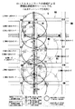
即ち、図9及び図10に示す例においては、自車両が図10に示すような走行路Gで示される誘導経路に沿って走行しており、現在道路U1を走行中の時、図中自車位置マークで示される自車両L3は、搭載している車両間通信機によって、円形の通信範囲内として示される自車L3ローカルネットワーク(L3)を形成可能となっている。
【0024】
図9及び図10の例においては、自車L3ローカルネットワーク(L3)を形成することが物理的に可能な車両としては、同一走行路Gを走行中の、自車両L3の後に位置する車両L2、自車両の前を走行している車両L4、その前の交差点C2を越えて前方を走行している車両L5、また、道路U1を走行しているものの図9に示すように逆方向に走行している車両R3、更に、自車両が走行している道路U1に交差点C2で交差する道路W1において、図中右側から交差点C2に入ろうとする車両S2、道路W1において図中左側から交差点C2に入ろうとする車両S3の合計6台の車両とローカルネットワークを形成することが可能となっている。
【0025】
その際に自車両を中心とした周辺車両ネットワーク形成するときには、自車両からは見えない車両とも通信を行うことができるようになり、それらの車両から、例えばカメラ映像を取り込むことが可能となる。その際には、自車両からは建物の陰で見えない箇所から自車両の前に飛び込んできそうな人をそれらの車両のカメラ映像から知ることができ、予め危険予防の対応をしておくことも可能となる。また、自車両直前の交差点におけるそれらのカメラ映像を同一画面に複数並列して表示することにより、その交差点について全ての方向から撮影した映像を見ることも可能となるため、事故多発交差点においても、運転者、その他の同乗者にとって安心して走行することもできる。
【0026】
図9及び図10に示す例においては、自車の前方を走行している車両L4は車間ネットワークを形成するための車両間通信機を搭載していないか、または搭載していても通信機をオフする等により利用していない車両であり、この車両とネットワークを形成することはない。なお、図9及び図10中において図面が錯綜するので図示していないが、自車とは逆方向に走行している、例えば車両R3とも車両間通信ネットワークを形成することが可能であり、その際には自車両の同一走行路ネットワーク、或いは渋滞ネットワークでは、その車両からの情報の利用可能性が少ないと判断されるときには予めそのネットワークには含まない車両として設定しておき、自動的に除外することもできる。但し、自車両の周辺の車両としてのドライブネットワークに組み込むことも可能である。
【0027】
上記のような自車L3のローカルネットワーク(L3)には、同一走行路Gにおいて前方を走行する車両L5のローカルネットワーク(L5)と接続しており、この時は車両L5のローカルネットワーク(L5)の中に自車両(L3)が存在するので、自車両L3と車両L5とは互いに情報、データの授受が可能となっている。また、この車両L5のローカルネットワーク(L5)中では、その前方の車両L6の前を走行する車両L7がローカルネットワーク(L7)を形成しており、前記と同様に両車両L5、L7が互いに情報、データの授受を可能としている。
【0028】
同様に、車両L7の前方において交差点C3を越えた道路上を走行している車両L8、更にその先の橋B1上の車両L9、更にその先の交差点C4の手前に車両L10が走行し、各々ローカルネットワークを形成し、互いに情報、データの授受を可能にしており、それにより、車両L10の情報等は自車両L3に対して、少なくともローカルネットワークL10、L9、L7、L3によって自車両にその情報等を取り込むことができるようになる。したがって、自車両が特定の交差点を通過しようとしたとき、その交差点の詳細な地図データを持っていないとき、その要求を送信することによって、ローカルネットワークで接続している車両の中からそのデータを所有している車両を探し、そのデータを一時的に利用することもできるようになる。
【0029】
また、例えば車両L10にカメラを備えているとき、そのカメラの映像を自車両L3に取り込むことも可能となり、自車両の遙か前方を走行する車両のカメラにより、実際の道路の混雑、渋滞の状況等をモニタ画面で見ることも可能となる。なお、自車両の後方にも同様のローカルネットワークの接続が形成され、自車両の後方を走行する車両に対しても同様の情報、及び自車両の情報等を自動的に伝達することができる。このようなカメラ映像の利用によって、遙か遠方も自由に見ることができる、いわゆる真のバードビューが可能となる。更に、例えば後で自車が右折する必要のある交差点のような特定の交差点を選択し、その交差点に近接している車両を自動選択して、その車両のカメラ映像を順次切り替え、常時特定の地点のカメラ映像を表示する、というような定点観測も可能となる。
【0030】
また、例えば自車両が信号の無い交差点C2を通過しようとするとき、道路W1を図中右側からこの交差点に入ろうとするローカルネットワーク(S2)を形成している車両S2の存在を、自車両のモニタ画面における車両マーク等で確認することができ、この交差点を低速で注意しながら通過する、というように、目に見えない場所にいる車両の状態を予め知ることによって、車両走行中の危険を回避することができる。
【0031】
このような情報の授受は、通常の車両間で行う以外に、例えば2輪車等の車両間でも可能であり、通信機が小型化した場合には歩行者がこれを所持することもでき、その際には、自車両の直前の道路に物陰から飛び出そうとする人の存在をモニタ画面の表示で知ることができ、それに対応した安全運転を行うように注意することもできる。このような携帯用のローカルネットワーク形成用通信機を所持するときには、前記のような車両間のローカルネットワークを利用して種々の情報の利用が可能となる。なお、その際には、前記車両間のローカルネットワークの他、持ち運びされるモバイル機器間のローカルネットワークの形成も可能となり、同様の情報の授受ができるようになる。
【0032】
更に、例えば混雑中の信号の無い交差点C2において、左折しようとしている車両S3が存在するとき、その車両S3の運転者との実際の会話によって、車両S3から「入れて下さい」という要望に対して、「はい、どうぞ」との挨拶、応答を行い、その車両を列内に入れることも可能となる。なお、自車両が前記車両S3の立場の時には、このようなやりとりにより、なかなか入りにくい混雑中の信号の無い交差点で、その車の列に容易に入ることができるようになる。このことは同様に、渋滞中で列をなしている高速道路に他の路線等からこの渋滞中の列に入るときも、同様の通信によって容易に入ることが可能となる。
【0033】
更に、図8に示すような情報センターの統計データをそのローカルネットワークに接続可能な他車の情報収集機能を利用することにより、例えば天候や季節毎の、特定の道路の交通渋滞情報、積雪時の交通規制情報、お祭り等のイベントの実行による交通規制情報、渋滞や混雑時において利用する地元の人が知っている程度の抜け道情報等の種々の情報を取り込むことが可能となり、無駄な時間を過ごすことなく、且つ安全運転が可能となる。なお、このような地元の人が知っている程度の抜け道路情報は、同一走行路ネットワーク中で各車両の走行路軌跡データを取り込み、その中に地元の人がいて抜け道を利用していたときには、そのデータを自動的に検索して取り込むことによって、特殊な抜け道も知ることも可能となる。
【0034】
なお、車両に環境センサとしてのカメラを搭載し、車両の走行状態に応じて適切な情報を運転者に提示する技術としては特許文献1に、また、他車との通信手段を搭載し、渋滞情報を相互に交換する技術は特許文献2に記載されている。
【0035】
【特許文献1】
特開平7−9882号公報
【特許文献2】
特開平9−180094号公報
【0036】
【発明が解決しようとする課題】
各車両に上記のような統一的機能を備えた車両間通信機を搭載し、各々がローカルネットワークを形成して、このような車両が多数集まることによって広範な情報伝達ネットワークを形成することにより、種々の情報を自動的に取り込むことができるようになるため、この情報伝達ネットワークによって更により具体的な利用法が検討されている。
【0037】
その一つとして、渋滞ネットワークをより効果的に利用することが考えられており、特に前記のような車両搭載カメラによって常時走行方向を撮影し、その映像を他の車両にも利用可能とすることが考えられている。その際には、通常の走行時にはナビゲーション用の地図を全面に表示している状態から、現在の渋滞の様子を自車両の前方を走行している車両の映像によって確認したいとき、車両間ネットワークの渋滞表示機能選択を行う等により、例えば図11に示すように、モニタ画面を2分割した左側画面に走行中の地図と、その地図上に渋滞ネットワークを形成すると共にカメラを搭載している車両を表示し、モニタ画面中の車両の一つを同図に示すように指で触ることによってそのタッチパネルの機能により指示を行い、指示された車両が撮影したカメラ映像をモニタ画面の右側に表示することが考えられている。
【0038】
このような手段により、渋滞に巻き込まれたとき、自分の車両の走行経路上での渋滞状況を、画面に表示された任意の車両のマークを触ることにより車両の指示を行い、その車両の前方の様子を見ることができる。また、この車両の前方が渋滞していることを確認したときには更にその先の車両のマークを触ることにより、現在の渋滞がどこまで続いているかの把握を容易に行うことができるようになる。
【0039】
しかしながら、図11に示すように、渋滞ネットワークに接続しカメラを搭載している車両のマークを地図画面上に表示する際には、車両用のモニタ画面の大きさには限界があり、特に対象となる車両が多数存在するときには、それらの車両のマークの重なりが多くなるため、表示が見にくくなるばかりでなく、車両のマークを指で触る際に別の車両に触ってしまうことが多くなり、適切な指示ができなくなる。特に車両が例え低速で走行している場合でも、運転者がこれを操作する際には小さな画面中の小さな車両マークに確実に触ることは困難となることが予想され、その際に車両の安全運転に支障を来すことも考えられる。
【0040】
更に、図11に示す方式でカメラで撮影した渋滞の状況の映像をモニタ画面に表示するときには、その車両のマークは地図画面上で大きく表示されることとなるため、表示されている車両が実際にはどのような地点を走行しているのかはわかりにくい。また、上記のような渋滞の状況をモニタ画面で確認するとき、前の車両の後部ばかりが撮影され、その走行の状態からある程度渋滞していることは確認できても、実際にどのような渋滞状況下を把握することができないことが生じる。
【0041】
車両の前方をカメラで撮影して、実際にその渋滞の程度を知るためには、上記のような通常の渋滞の列においてその列の中に埋もれていて前の車両の後部を大きく撮影している車両のカメラの映像より、交差点の手前で停止している車両のカメラが撮影した映像の方が、その前方の視界が開けているため渋滞の状態をより良く把握できる。一般的に、渋滞しているときの走行において、交差点に入るときには自分の車両が交差点の中で停止してしまい、他の車両の走行の邪魔にならないように調節して走行することが行われる。そのため、渋滞中の走行路において、交差点の手前で停車している車両のカメラの映像は、交差点の状態及び自車両の走行路の渋滞の状態を良く表しているということができる。
【0042】
それに対して図11に示す方式では、車両のマークが地図画面上に大きく表示されるため、各車両が交差点に対してどのような状態にあるかがわからず、同図に示すように交差点の手前で停車している車両を見つけてその映像を表示することは、実際には極めて困難であり、偶然性を必要とする。
【0043】
一方、前記のような車両用情報ネットワークシステムによって、例えば現在走行している走行路上で、自車両の前方の路上で事故が発生してその道路がふさがれてしまったとき、その情報は事故を起こしてしまった車両から、或いはその車両の後方を走行していた車両から後続の車両に対してその旨の情報を順次伝達することが可能となる。
【0044】
従来このような事故が発生したときには、交通情報センターに情報が集められ、確認作業終了後その情報をこの事故に関係する地域に対して、VICS、或いは放送等の手段で配信することとなる。そのため事故が発生してからしばらく経ってこの事故車の後方を走行する車両にも伝達されることとなる。
【0045】
それに対して、前記のような車両用情報ネットワークによって、この事故に最も影響のある後続車両に対して直ちにその事故の状態を伝えることができるため、この車両用情報ネットワークシステムが期待されている。
【0046】
しかしながら、このような事故の発生によりその道路が通行できなくなったことがわかっても、全ての車両が高性能のナビゲーション装置を搭載し、正確な迂回路を直ちに演算して走行を行うことができるとは限らず、データの古いナビゲーション装置を搭載した車両、演算速度の極めて遅いナビゲーション装置を搭載した車両、モニタ画面を搭載していてもナビゲーション装置を搭載していない車両等においては、前記のような事故に対応した正確な迂回路を直ちに得ることができず、高性能のナビゲーション装置のデータの利用を望む車両も多い。
【0047】
なお、この情報を受ける後続車両においてナビゲーション装置を搭載している車両はこのデータを直接利用することができるが、ナビゲーション装置を搭載していない車両でもモニタ画面を搭載しているときにはそこに表示することができ、モニタ画面の搭載していない車両でも、先行する車両の音声案内を利用して迂回路を走行することも可能である。このような状況は、前記のように走行路上で交通事故が発生した場合以外に、前記のような渋滞時においても、適切な迂回路を演算し、後続の車両に伝達することも考えられる。
【0048】
また、上記のように事故車両により通行止めになったとき、前記のように高性能のナビゲーション装置を搭載した車両から迂回路の情報が伝達されたときでも、必ずしもその迂回路が全ての後続車両にとって適切とは言えず、その車両にとって最も適切でも、後続の車両には他の適切な迂回路が存在する場合もある。
【0049】
例えば前記図10の例において、この状態で車両L9が橋B1の上で事故を起こし橋B1が通行不能になったとすると、その後続車両のうち車両L7は迂回路を演算し、交差点C3から右折して道路W2を走行し、交差点C11で左折し、橋B3を通り、交差点12で左折して道路W3を走行し、交差点C4で右折して予定の走行路Gに戻るように迂回路を設定することが可能である。したがってこの情報を後続の車両L5に伝えることにより、車両L5がこの情報を元に同様の迂回路を走行することは適切な迂回路ということができる。
【0050】
しかしながら、その迂回路の情報を更に後続の車両である自車両L3、及び更に後続の車両L2に伝えて迂回路情報として利用してもらうとき、例えば自車両L3が平均程度の性能のナビゲーション装置を搭載し、そこで迂回路を演算したときには、交差点C2で左折して道路W1を走行し、交差点C6で右折して道路U2を走行し、交差点C7、橋B2を通り、交差点C8で右折し、道路W3を通って交差点C4に至り、ここで左折して予定の走行路Gに戻るように迂回路が演算されたとき、この迂回路は前記のように車両L7が演算した迂回路より適切な迂回路ということができる。
【0051】
また、迂回路の利用に際して、1つの迂回路に多くの車両が集中することは好ましくなく、できることならば分散することが好ましいが、前記のように後続車両が他の迂回路を演算してそれを利用することは特に好ましい。したがって、迂回路を演算して後続の車両にその情報を伝達するに際して、更に適切な迂回路が存在するか否かをチェックした後に迂回路が提示されることが好ましいのに対して、現在は適切な手段が存在しない。
【0052】
したがって本発明は、車両間通信機により車両間でネットワークを形成して情報の授受を行うに際して、自車両の前方を走行する車両に搭載したカメラで撮影した映像をモニタ画面に表示するとき、交差点の手前側に近い車両を自動的に選択し、その車両のカメラの映像を表示することができるようにした車両用情報処理装置を提供するとともに、走行路の交通状態に応じて迂回路を演算して後続の車両に伝達するとき、これを受信した車両が更に他の車両の迂回路、または自車両演算の迂回路とを比較し、より適切な迂回路を選択することができるようにした車両間情報処理装置を提供することを目的とする。
【0053】
【課題を解決するための手段】
本発明に係る車両用情報処理装置は、上記課題を解決するため、車両間通信機を備え、車両間通信により同一走行路に関連する車両を選択して通信を行う車両間ネットワーク形成手段と、前記走行路を分岐路単位に分割する分岐路分割手段と、前記分岐路単位中でカメラ搭載車両を検出するカメラ搭載車両検出手段と、前記分岐路単位中で前方の分岐路に最も近いカメラ搭載車両を選択する車両選択手段と、前記車両選択手段で選択した車両から受信したカメラ映像をモニタ画面に表示する画像表示手段とを備えたものである。
【0054】
また、本発明に係る他の車両用情報処理装置は、前記車両選択手段が、分岐路単位中でのカメラ搭載先頭車両のみを選択したものである。
【0055】
また、本発明に係る他の車両用情報処理装置は、前記モニタ画面にが、複数の車両からのカメラ映像を並べて表示するものである。
【0056】
また、本発明に係る他の車両用情報処理装置は、前記モニタ画面には、地図画像と前記カメラ映像を表示し、地図画像には前記車両選択手段で選択した車両の存在する分岐路単位を他と区別可能に表示するものである。
【0057】
また、本発明に係る他の車両用情報処理装置は、前記車両選択手段が、利用者の指示により車両を選択する分岐路単位を順に変更するものである。
【0058】
また、本発明に係る他の車両用情報処理装置は、車両間通信機を備え、車両間通信により同一走行路に関連する車両を選択して通信を行う車両間ネットワーク形成手段と、前記走行路を分岐路単位に分割する分岐路分割手段と、他車両から受信した迂回路と、更に他車両から受信した迂回路または自車両演算の迂回路とを、前記分岐路分割手段で分割した分岐路単位により選択を行う迂回路選択手段を備えたものである。
【0059】
また、本発明に係る他の車両用情報処理装置は、前記他車両からの迂回路は、事故情報、または渋滞情報と共に受信するものである。
【0060】
【発明の実施の形態】
本発明の実施の形態を図面に沿って説明する。図1は本発明による車間通信による情報ネットワークシステムを形成して情報の授受を行うに際して、特に同一走行路上の先行車両のカメラ映像を交差点単位で自動表示し、また渋滞時においてネットワーク内の車両が迂回路を演算して提供する際、これを受信した車両は交差点単位のデータにより更に適切な迂回路を選択することができるようにした車両間情報処理装置の機能ブロック図を示している。
【0061】
図1に示す実施例においては、自車両用として車両用情報処理装置1を備え、この車両用情報処理装置1内にナビゲーション制御装置11を備え、システム制御部40によって車間ネットワーク用通信機2と共に統合的に制御されている。ナビゲーション装置11にはモニタ6、ハードディスクやDVD等のデータ記録装置7を備えるとともに、ナビゲーション制御装置11、及び後述する車間ネットワーク用通信機2で用いる自車位置及び進行方向を求めるためにも使用される車速・方位検出部8、GPS受信器9を備え、更に車両用情報処理装置1及び車間通信ネットワーク用通信機2に対して利用者の指示を入力するための指示信号入力部10を備えている。
【0062】
ナビゲーション装置11には自車位置進行方向演算部20を備え、前記車速・方位検出部8のデータ、及びGPS受信器9からの信号を入力し、自車両が現在走行している地点の位置データ、及び進行方向を演算し、そのデータを地図画像形成部22及び誘導経路演算部24に出力するとともに、後述するように車間ネットワーク用通信機2における送信部5の自車位置データ41、及び進行方向データ42として出力する。
【0063】
データ・情報読込部21では、前記ハードディスクやDVD、更にはCD等のデータ記録装置7から所望の地図データや施設情報を読み込み、地図画像形成部22に出力して自車位置を中心とした3D等の所定形式の地図画像を形成し、画像表示部19に出力するとともに、施設情報23も画像表示部19に出力して必要な情報をモニタ6に表示する。
【0064】
ナビゲーション装置11には従来の装置と同様に誘導経路演算部24を備え、その演算の結果は誘導経路設定部25を介して画像表示部19に出力し、地図画面上に重ねて表示する。誘導経路演算部24には迂回路演算部26を備え、後述する車間ネットワーク用通信機2の受信部4から渋滞情報35、或いは事故情報36が入ったとき、更には別途図示されないVICS受信器から誘導経路上に渋滞が発生したことを検出したときには、自動的に迂回路を演算することができるようにしている。
【0065】
演算した迂回路は誘導経路設定部25における迂回路選択部27に出力し、後述するように車間ネットワーク用通信機2の受信部4から迂回路データ34を外部の車両から受信したときには、その受信した迂回路と前記自車両が演算した迂回路とのいずれが現在の自車両にとって適切かを検討して選択し、また選択結果を利用者に提示して確認を依頼し、決定された迂回路を画像表示部19に最終的に表示して新たな誘導経路とする。また、演算した迂回路は後続車両等の利用に供するため、車間ネットワーク用通信機2にも出力する。
【0066】
図1に示すナビゲーション装置10の画像表示部19には、後述する車間ネットワーク用通信機2の受信部4から、同一走行路を走行中の先行する車両に備えたカメラで撮影したカメラ撮影映像33を入力し、モニタ6の画面を2分割した図中右側の部分にこれを表示することができるようにしている。また、車両用情報処理装置1にはネットワーク形成車両検出部12を備え、後述するように利用者が指示し選択したネットワークが形成された車両を検出してネットワーク形成車両の管理を行い、必用に応じてモニタ6の地図画面にこれらの車両を表示することができるようにしている。
【0067】
車両用情報処理装置1には分岐路単位分割部13を備え、前記のように例えば同一走行路のネットワークを形成した車両について、交差点等の分岐路部分で分割して分岐路単位を形成し、後述するように、カメラ撮影映像の表示、及び適切な迂回路の選択に際してそのデータを利用する。
【0068】
カメラ搭載車両検出部14は、ネットワーク形成車両検出部12で検出した例えば同一走行路ネットワーク等のネットワーク形成車両の中でカメラを搭載した車両を検出するものであり、ここでは単にカメラを搭載しているだけではなく、実際にこれを作動し、その映像をネットワークに公開している車両を検出する。このカメラ搭載車両検出部14においては、前記分岐路単位分割部13のデータにより、分岐路単位毎にカメラを搭載している車両を検出することもできるようにしている。
【0069】
車両選択部15においては、ネットワーク形成車両検出部12で形成したネットワーク形成中の車両の中から所望の車両を選択するものであり、その際には、分岐路単位分割部13のデータにより分岐路単位の中から特定の車両を選択することができ、またカメラ搭載車両検出部14からのデータによりカメラを搭載した車両の中から特定の車両を選択し、更に分岐路単位毎のカメラ搭載車両の中から特定の車両を選択する等の種々の態様での車両の選択を行うことができるようにしている。
【0070】
車間ネットワーク用通信機4には通信機全体の制御を行う車間通信制御部3を備え、システム制御部40によって車両用情報処理装置1と統合した制御を行い、受信部4、送信部5、更には車両用情報処理装置1との信号の授受の制御を行う。この車間通信制御部3には受信データ自動送信部38を備え、車間ネットワークの機能として例えば同一路線を走行している自車両より後方の車両が、自車両より前方の車両の情報やデータを取り込もうとしたとき、中継機器としての機能を行うため、それらの情報やデータを特に取り込むことなく、そのまま送信部5から自動的に送信を行うことができるようにしている。
【0071】
車間通信制御部3には送信・受信データ選択制御部39を備え、送信部5から他の車両に送信するデータの選択を行い、また、受信部4で受信するデータの指示を行う。これらの指示は、指示信号入力部10で選択し指示したネットワークの種類選択信号により自動的に特定のデータの送信、及び受信を行うようにし、また、利用者の指示により特定のデータを送信、或いは受信を行い、更には各種のデータ送信要求を行うことができるようにしている。
【0072】
受信部4においては種々の情報やデータの受信が可能となっており、図示の例においては例えば前記図8に示すように、この車両間通信ローカルネットワークに接続されている種々のネットワーク中に情報センターが存在し、その統計データベースの利用が可能なときには、送信部5の情報・統計データ要求47で要求した情報やデータをここで取り込む。また、インターネット情報32についても同様に、図8に示すようにこの車両間通信ローカルネットワークにインターネット接続部分が存在するときには、送信部5のインターネット情報要求48で要求した情報をここで取り込むようにしている。
【0073】
また、カメラ撮影映像33を受信可能としており、このネットワークに接続している車両の中でカメラを搭載している車両のうち、利用者の指示したもの、或いは車両選択部15で選択した車両のものを自動的に複数受信することができるようにし、必用に応じてカメラ映像をスクロールして選択表示する。なお、このカメラ撮影映像は、モニタ6の2分割した画面に、選択された1つ或いは複数の映像を表示する。
【0074】
受信部4においては迂回路データ34も受信可能としており、渋滞時に他の車両が演算して送信してきた迂回路を受信する。この迂回路データは前記のようにナビゲーション装置の迂回路選択部27で自車両で演算した迂回路と比較し、自車両の迂回路より適切であると判断されたときには自車両においてこれを利用することとなる。渋滞情報35及び事故情報36も受信可能としており、同一走行路において前方を走行する車両が渋滞に入ったことを検出したとき、或いは事故が発生したことを検出したときこれを後続の車両に伝達すると、この情報をここで受信し、前記迂回路演算部26はこの情報に基づいて迂回路の演算を行う。更に必用に応じてその他の情報やデータ37を受信し、車両用情報処理装置1で使用する。
【0075】
一方、送信部5からは、車間ネットワーク形成時の最低限のデータとして、自車位置データ41、進行方向データ42、ネットワーク種類コード43等が送信される。したがって利用者が車間ネットワークに入ることを選択したときには、自動的にこれらのデータがネットワーク形成車両に対して送信され、それにより他の車両は自車両の位置、及び進行方向を受信してモニタ画面の地図上にその存在を表示することができ、更に必用に応じて進行方向も表示可能となる。
【0076】
また、車間ネットワークに入るとき、各種のオプションのネットワークの内利用者が希望するネットワークを選択したときには、そのネットワークの種類に対応するオプションデータ45を送信する。それにより、例えば渋滞ネットワークを選択したときには、自車両で演算した迂回路を他の車両に対して送信可能としている。
【0077】
送信部5では上記のような車間ネットワーク形成用のデータ送信の他、接続したネットワーク中に情報センターが存在するときには、例えば季節や時間による特定地域の渋滞予測、交通規制のデータ、地元の人が知っている程度の抜け道情報等を要求することができ、またインターネット情報要求48により希望するURLから所望の情報の取り込み要求を行うことができ、必用に応じてその他の情報、データの取り込み要求49を行うことができるようにしている。
【0078】
上記のような機能ブロックから構成される車両用情報ネットワークシステムにおいては、例えば図2乃至図6に示すような作動フローによって順に所望の作動を行わせることができる。図2には、車間ネットワーク形成時において特に事故や渋滞時に行う処理の作動を示しており、最初車間ネットワークへの接続(ステップS1)から開始される。これは利用者が車間通信機の作動を開始することにより、或いはその後所定の操作を行うことにより開始される。なお、図2に示す例においては、後述するような事故発生時の迂回路の演算、演算結果の他車への提供等を渋滞ネットワークで行う例を示しているが、これを例えば緊急ネットワーク等の他のネットワークにおいて、或いは独自のオプションネットワークにおいて行わせることができる。
【0079】
次いで最小限情報の出力準備がなされる(ステップS2)。この時の最小限情報としては、例えば図1の車間ネットワーク用通信機2における送信部5に示されるように、自車位置データ41、進行方向データ42、ネットワーク種類コード43等の予めネットワークシステムの構築に際して決められた最小限データが、他車のネットワーク形成車両の検索作動に応じて送信するために準備される。
【0080】
次いでこの作動フローの例においては、渋滞ネットワークを選択したか否かを判別する(ステップS3)。この判別に際しては図1の指示信号入力部10において、モニタ画面に表示された設定入力画面に沿って順次選択設定を行うとき、その選択した結果を記憶している車間通信制御部3のデータによって検出することができる。
【0081】
ステップS3において渋滞ネットワークを選択したと判別したときには、渋滞ネットワーク内での情報の授受を行う(ステップS4)。この時には、ネットワーク形成車両における前記最小限情報は当然取り込まれ、また同様のデータが他車に取り込まれるとともに、その他同一走行路を走行している車両、更にはこの走行路に関係すると思われる車両が、自車における渋滞ネットワーク対象車両として選択され、それらの車両に対して渋滞ネットワーク形成時に提供する情報として予め決められている情報やデータを送受信する。
【0082】
次いで図2に示す作動フローの例においては、渋滞ネットワーク形成車両をモニタ画面に表示し(ステップS5)、モニタ画面上で現在渋滞ネットワークを形成している車両が地図上でどのような状態になっているかがわかるようにしている。その表示は特に車両マークを表示する必要はなく、例えば対応する車両の位置に赤色の点を点滅させる等により表示させることができる。またその際、最小限情報の授受を行うネットワーク形成車両も地図画面上に表示するときには、その表示とは別に、例えば色を異ならせる等によって区別して表示しても良い。
【0083】
これらのネットワーク形成車両の表示が地図画面を見る際に邪魔になるときは、適宜その表示を消すようにしても良い。なお、これらの作動は図1の車両用情報処理装置1におけるネットワーク形成車両検出部12において、対応するネットワークを形成している車両が検出され、画像表示部19において種々の態様でこれを表示することができる。
【0084】
その後、他車から走行経路上の事故情報を受信したか否かを判別する。この事故情報は、事故を起こした車両から緊急情報として直接受信することもできるが、後続車両がその状況を把握したときには、その旨の情報を更に後続する車両に対して送信するとき、これを受信することもできる。この時の事故情報としては、例えば事故の発生地点、事故の程度等が受信される。
【0085】
ステップS6において他車から走行路上の事故情報を受信したと判別したときには、自車両において迂回路を演算し(ステップS7)、次いで他車から迂回路のデータを入力したか否かを判別する(ステップS8)。なお、図1に示す例においては自車両に搭載したナビゲーション装置に迂回路演算部26を備えた例を示しているので、図2に示す作動フローもここで迂回路を演算しているものであるが、自車両搭載のナビゲーション装置に迂回路を演算する機能がないとき、更にはナビゲーション装置を搭載していないときには当然この迂回路の演算は行われず、以降ステップS11に進むこととなる。
【0086】
ステップS8において他車から迂回路のデータを入力したと判別したときには、この実施例においては、自車演算の迂回路と他車からの迂回路とを比較し、適切な方を選択する処理を行う(ステップS9)。なお、この処理は後述するように図3に示す作動フローによって行われ、自車演算の迂回路と他車演算の迂回路の内適切なものが自動的に選択される。また、この処理は図1における迂回路選択部27において行われる。
【0087】
次いでこのようにして選択された迂回路をモニタ画面上に表示し(ステップS10)、利用者に対してその迂回路を走行するか否かの確認を促す(ステップS11)。また前記ステップS8において他車から迂回路のデータを入力しないと判別したときには自動的にその迂回路が選択され、ステップS10に進んでその迂回路を表示する。
【0088】
図示の例においては、ステップS11ではその迂回路を走行するか否かの判別の結果、走行するときにはステップS14に進み、走行しないときにはステップS12に進んで他の迂回路の候補はあるか否かの判別を行い、他車からの迂回路、或いは自車演算の迂回路等でその他のものが存在するときは他の迂回路を表示する(ステップS13)。その表示の後はステップS11に戻り、同様の作動を繰り返し、その過程で利用者がその迂回路を走行すると決定したとき、ステップS14に進んでその迂回路の走行が開始され、その後ステップS4に進み同様の作動を繰り返す。ステップS12において他の迂回路が存在しないと判別したときには、同様にステップS4に戻ってそのまま走行を行い、再び渋滞ネットワーク内での情報の授受を行う。
【0089】
なお、上記の例においては、後述する図3に示す手法により自車両による迂回路と他車両による迂回路のいずれかを自動的に選択した例を示したが、そのような自動選択を行わない際には、ステップS10において全ての迂回路をそれぞれ異なった色で表示し、ステップS11において利用者がその中から適切と思われるものを選択するようにしてもよい。
【0090】
前記ステップS9における自車演算の迂回路と他車からの迂回路との比較選択処理に際しては、例えば図3に示すようにして行うことができる。即ち、最初自車演算の迂回路は他車演算の迂回路より所定距離以上長いか否かの判別を行い(ステップS31)、例えば2倍の距離がある等によりあまりにもその距離が長いときには、自車演算の迂回路より他車演算の迂回路の方が適切なものとして、一応自車演算の迂回路を記憶した後(ステップS36)、受信した他車からの迂回路を選択する(ステップS37)。
【0091】
前記ステップS31において、自車演算の迂回路は他車演算の迂回路より所定距離以上長くはないと判別されたときには、例えある程度は自車演算の迂回路が長くても、自車の先を走行する車両の多くものが受信した迂回路を通ることになるので、多くの車両がその道路に集中することが考えられ、それらの車両のほとんどが通らない自車演算の迂回路の方が早く着くこともあり得ることを考慮し、少しくらい距離が長い程度では自車演算の迂回路を選択する方向に進むものとする。
【0092】
ステップS31において、自車演算の迂回路が前記のように例えば2倍以上のように特別に長いものではないと判別したときには、自車両が演算した迂回路は、迂回路を送信してきた車両の後方で迂回するような迂回路になっているか否かを判別する(ステップS32)。
【0093】
この状態は、例えば図10に示す例において、同一走行路G上を走行しており、橋B1上の車両L9が事故を起こしてこの道U1を塞いだとき、その情報がこの事故車L9から直接、或いは後続の車両L8からその旨の情報が図示のネットワークにより後続の車両に伝達されるとき、例えば車両L7が迂回路を演算した結果、分岐路としての交差点C3、C11、C12、C4で元の走行路Gに戻る迂回路を演算して発信したとき、自車両L3が迂回路を別途演算し、交差点C2、C6、C8、C4で元の迂回路Gに戻る迂回路を演算したときには、前記判別において、自車演算の迂回路は迂回路を送信した車両L7の後方で迂回すると判別される。
【0094】
このようなときは多くの場合、自車演算の迂回路は先を進む車両より多くの候補の中から選択された迂回路のため、適切な迂回路である場合が多いので、自車演算の迂回路を選択する(ステップS33)。また、自車演算の迂回路は迂回路を送信した車両の後方で迂回するものではないと判別したときには、後に他車演算の迂回路が利用されることもあることを考慮し、その迂回路を記憶する(ステップS5)。
【0095】
ステップS33において自車演算の迂回路を選択したときには、この迂回路が先に送信されてきた他車演算の迂回路より良いものであることが考えられ、少なくとも参考データとしてもらうためにこの自車演算の迂回路を後続の車両等の他車両に送信する(ステップS34)。その後、前記ステップS37で受信した他車からの迂回路を選択した場合を含めて、前記図2のステップS10に進み(ステップS38)、選択した迂回路の表示を行うこととなる。また、ステップS35及びステップS36で記憶した別の迂回路は、図2のステップS12において他の迂回路の候補はあるか否かの判別に際して参照され、その後必用に応じて利用される。
【0096】
上記のような事故情報に基づく迂回路の演算は、図10から明らかなように、各車両がどの交差点間、即ち分岐路間に存在するかによって変わることが多い。したがって、迂回路を送信している車両が自車両と同じ交差点間に存在するときは、同じ迂回路にすることが適切な場合が多いが、別の交差点間、即ち別の分岐路単位間に存在するときには別の迂回路が存在する可能性が大きくなる。このように、事故情報に基づく迂回路の選択処理は、後述する渋滞ネットワーク中での先行車両のカメラ撮影映像の表示処理と同様に、車間ネットワーク内での情報処理を分岐路単位で分割して考慮するする点において共通する課題ということができる。
【0097】
上記作動は図2におけるステップS6において、他車から走行経路上の事故情報を受信したときの一連の作動として説明したものであるが、このステップS6においてこのような事故情報を受信しないときにはステップS15に進み、渋滞を検出したか否かを判別する(ステップS15)。渋滞の検出に際しては、例えば車両の速度が時速20km以下が5分程度継続したときのように、自車の走行状態によって検出することができ、別途VICS情報により知ることもできると共に、前方を走行する車両からの情報によっても検出することもできる。ここで渋滞を検出しないときにはステップS4に戻って同様の作動を繰り返すこととなる。
【0098】
ステップS15において渋滞を検出したと判別したときには、選択したネットワーク中で先行車両のカメラ撮影映像の取り込みが可能であるか否かの判別を行う(ステップS16)。この判別に際して、前記のようにして形成した渋滞ネットワーク中の車両で、最低限の条件として、同一走行路の自車両より前方を走行している車両の中にカメラを搭載している車両が存在するか否かを判別することにより行い、存在しないときにはその後の処理を行うことはできないのでステップS4に戻って同様の作動を繰り返す。
【0099】
このステップS16の判別に際して、この車両間ネットワークシステムの普及が始まる時において、またカメラを搭載する車両が未だ少ない状態においては、次のステップに進めないことが考えられるが、この車両間ネットワークで使用する機器は比較的安価に提供することができるのでその急速な普及が考えられると共に、現在車両にカメラを搭載して種々の運転補助を行う研究が進められており、しかも近年携帯電話にデジタルカメラが搭載され、動画も取り込めることができるようになっていることからもわかるように、今後車両にテレビカメラを搭載することが急速に普及することが予想されている。
【0100】
このような車両間ネットワーク、車両のカメラ映像の利用が普及すると、多くの車両がこのシステムの利用が可能となるので、前記ステップS16の判別では、選択したネットワーク中で先行車両のカメラ撮影映像の取り込みが可能と判別され、次のステップS17に進み、渋滞ネットワーク中での先行車両のカメラ撮影映像の表示処理を行う。この処理は後述するように、図4または図5に示す作動フローによって順に行うことができる。
【0101】
後述するようにステップS17の処理が終了した後は、図示実施例においては迂回路の提示が必要であるか否かの判別を行い(ステップS18)、この渋滞を抜けるための迂回路の提示が必要である旨の利用者からの指示があったとき、或いは渋滞を検出したときには特別の理由がない限り迂回路の提示を行うものとして、前記ステップS7に進む。その後は他車からの迂回路のデータを加味しながら、前記と同様の作動を行う。ステップS18において迂回路の提示は必要ないと判別したときには、ステップS4に進み、以下同様の作動を繰り返す。
【0102】
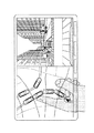
前記ステップS17における渋滞ネットワーク中での先行車両のカメラ撮影映像の表示処理に際しては、例えば図4に示すように、最初自車位置から先の走行道路でカメラを備えた車両が存在する分岐点単位を選択する(ステップS41)。この分岐点単位としては、例えば図6の画面例における左右2分割画面において左側画面に示される地図では、説明の便宜上、その分岐点単位が信号のある交差点で区切られたものとして示しており、図示の例においては自車両が含まれる図示されない交差点から「新谷」交差点迄と、「新谷」交差点から「稲崎」交差点迄と、「稲崎」交差点から「御坂」交差点迄と、「御坂」交差点から「菅山」交差点迄と「菅山」交差点から図示されない交差点迄の合計5つの分岐点単位が示されている。なお、前記図4におけるステップS41において選択を行う交差点単位は、前記図10に示されるような車両間ローカルネットワークが接続した範囲内の分岐点単位となる。
【0103】
ステップS41における分岐点単位の選択に際して、前記図2のステップS16において、選択したネットワーク中で先行車両のカメラ撮影映像取込可能か否かの判別で、既にネットワーク中でカメラを搭載してその映像を提供する用意がある車両が存在することが確認されているので、ここでは少なくとも1つの分岐点単位を選択することができる。図6及び図7の画面例においては、説明の都合上全ての分岐点単位が選択された例を示している。
【0104】
次いで図4に示す実施例においては、該当する分岐点単位は3個以上あるか否かの判別を行っている。この判別において3個以上あるか否かの判別を行っているのは、後述するように画面に3個の映像を表示するようにしているためであり、この画面に2個の映像を表示する際にはこのステップでは該当する分岐点単位は2個以上あるか否かの判別を行うこととなり、同様にn個の映像を表示する際にはn個以上あるか否かの判別を行うことになる。
【0105】
前記ステップS42において3個以上あると判別したときには、自車の分岐点単位を含め、3個先の該当分岐点単位において、前方分岐点に近い車両のカメラ映像を順に画面に表示する(ステップS43)。このような作動によって表示された例を図6に示しており、2分割した画面の右側に、更に縦に3分割した画面中にそれらの映像が順に表示されている。なお、このように表示される映像としてはビデオカメラのほか、所定間隔で連続的に撮影することができる静止画撮影カメラの映像でも良い。
【0106】
この画面例においては、3分割した一番下の映像は、自車両の前方に存在する「新谷」交差点迄の分岐点単位において、カメラを備えた車両のうちできる限りこの分岐点に近い車両のカメラの映像を取り込むように選択した結果表示されたものであり、この分岐点単位においては、 新谷交差点の部分を直接撮影することができる車両が存在しない結果、渋滞中の道路において比較的交差点に近い箇所に停車し、或いは低速で走行している車両からの映像を表示した例を示している。
【0107】
それに対して3分割した画面中、中央に表示されている「稲崎」交差点については、「新谷」交差点から「稲崎」交差点迄の分岐点単位の中でカメラを搭載した車両の内、前方の分岐点、即ち「稲崎」交差点に最も近い車両は交差点の直前で停車している車両であり、その結果稲崎交差点の様子が映し出されている。同様に3分割した画面中最上段に表示されている「御坂」交差点についても、その交差点の直前に停止している車両からの映像が表示されている。
【0108】
図示実施例においては、2分割した画面の左側に表示されている地図において、図中右側に表示されている映像の交差点単位を示すため、その交差点単位の前方の交差点に対する信号表示部に赤の太枠等により利用者にとってわかりやすい表示を行っており、更に2分割した画面の右側画面においては、その画面を更に縦に3分割した各カメラ映像の右上に、対応する分岐路単位の前方の交差点名を表示し、両者の対応が明瞭にわかるようにしている。この3個の映像を見ることにより利用者は、少なくとも御坂交差点迄は渋滞が続いていることがわかる。
【0109】
図4において、その後ステップS44に進み、更に前方の分岐点単位のカメラ映像表示の指示があるか否かを判別する。この判別は、図2の指示信号入力部10から利用者がその指示を行ったか否かによって判別することができる。なお、車両の信号入力部については、多くの機器の操作をコンソールボックスの最上部等の所定の位置に設けたジョイスティック式等の集中コントロールコマンダーを用い、ハプティック制御により操作を行うことが提案され、一部で実用化されているが、このような操作機器を用いることにより容易に前記操作を行うことができる。
【0110】
ステップS44において更に前方の分岐点単位のカメラの映像表示の指示があったと判別したときには、指示された分岐点単位が存在するか否かの判別を行い(ステップS45)、存在するときには指示されたとおり、1つ先の分岐点単位を含んだ、3個の該当分岐点単位で、前方分岐点に近い車両のカメラ映像を順に画面表示する。それにより、例えば図7に示すように、「稲崎」交差点迄の分岐点単位、「御坂」交差点迄の分岐点単位、「菅山」交差点迄の分岐点単位が選択され、前記と同様にこれらの分岐点単位の内前方の交差点に最も近いカメラを搭載した車両が選択され、その映像を画面に前記と同様に表示する。
【0111】
その結果、図7に示す例においては、2分割した左側の画面においては選択した分岐点単位を示すために対応する信号に対して他と容易に識別可能な表示を行うとともに、右側の画面において縦に3分割した各々の映像の右上に各分岐点単位を示す交差点名を表示している。この例においては、1つ先の分岐点単位として「菅山」交差点が選択され、その映像が最上段に表示されており、この画面においてはその前方には渋滞が存在せず、したがって現在自車両の周辺に生じている渋滞は少なくとも「御坂」交差点から「菅山」交差点の間で解消していることがわかる。
【0112】
前記ステップS46において1つ先の分岐点単位迄に映像表示を移した後は、ステップS44に戻って更に前方の分岐点単位のカメラ映像表示の指示があるか否かを判別し、利用者が更に同様の操作を行うか否かを検出し、以下同様の作動を繰り返す。また、前記ステップS42において、該当する分岐点は3個以上存在しないと判別したときには、ステップS47に進み、表示可能な該当分岐点単位で、前方分岐点に近い車両のカメラ映像を順に画面表示する。
【0113】
したがって、例えば該当する分岐点単位が2個しか存在しないときには、その2個を横に2分割した画面の右側画面を更に縦に2分割し、この中に表示することができる大きさでそれらを表示する。また、該当する分岐点単位が1つしか存在しないときには、その1つだけを横に2分割した画面の右側画面全体に1つのカメラ映像を表示する。その際には、前記図11の右側画面に示すような1つのカメラ映像が表示されることとなる。
【0114】
また、前記ステップS44において、更に前方の分岐点単位のカメラ映像表示の指示が行われなかったと判別したとき、及びステップS45において、指示された分岐点単位は存在しない時、即ち該当する分岐点単位が3個しか存在しないときか、その後この作動を繰り返すことにより全ての分岐点単位の映像を表示したとき、更に、ステップS47において該当する分岐点単位は2個以下のため、それ以上表示する映像が存在しないときには、ステップS48において前記図2におけるステップS16に進んで図2の作動を行うこととなる。
【0115】
上記実施例においては、分岐点単位にカメラを搭載した車両が存在するときには全て映像表示の選択の対象とした例を示したが、この車間情報ネットワークシステムが普及した際には、原則として交差点の直前で停止、或いは低速で走行している車両が存在する状態となるので、交差点の直前で停止、或いは走行している車両が存在する分岐点単位のみを選択することにより、前記図6の画面例における最下段の映像のように、ほとんど前の車両の後部しか映っていない映像を表示することを無くすことができる。
【0116】
その際の作動フローは図5に示すように、前記図4に示す作動フローを基準とし、前記ステップS43においては自車の分岐点単位を含め、3個先の該当分岐点単位で、前方分岐点に近い車両のカメラ映像を順に画面表示するようにしたのに対して、図5に示す作動フローではステップS53において、前記「前方分岐点に近い車両」に代えて、「前方分岐点直前の車両」としている。同様に図4のステップS47における「前方分岐点に近い車両」に代えて、図5のステップS57において「前方分岐点直前の車両」とし、更に図4のステップS46における「前方分岐点に近い車両」に代えて、図5のステップS57において「前方分岐点直前の車両」としており、このような作動フローにより容易に対応することができる。
【0117】
【発明の効果】
本発明に係る車両用情報処理装置において、車両間通信機を備え、車両間通信により同一走行路に関連する車両を選択して通信を行う車両間ネットワーク形成手段と、前記走行路を分岐路単位に分割する分岐路分割手段と、前記分岐路単位中でカメラ搭載車両を検出するカメラ搭載車両検出手段と、前記分岐路単位中で前方の分岐路に最も近いカメラ搭載車両を選択する車両選択手段と、前記車両選択手段で選択した車両から受信したカメラ映像をモニタ画面に表示する画像表示手段とを備えたものは、車両間の通信手段によって車両間でネットワークを形成してデータの授受を行うに際して、自車両の前方を走行する車両に搭載したカメラで撮影した映像をモニタ画面に表示するとき、交差点に近い地点を走行している車両を自動的に任意に選択することができ、その車両のカメラの映像をモニタ画面に表示することができる。
【0118】
また、本発明に係る他の車両用情報処理装置において、前記車両選択手段が分岐路単位中でのカメラ搭載先頭車両のみを選択したものは、モニタ画面に表示するカメラ映像は常に分岐路の先頭車両であり、あまり分岐路の様子が分かりにくい分岐路から離れていて他車両の後を撮影しているカメラ映像を表示することがないので、分岐路の様子をわかりやすく表示することができる。
【0119】
また、本発明に係る他の車両用情報処理装置において、前記モニタ画面が複数の車両からのカメラ映像を並べて表示するものは、走行道路上の車両の走行状態を全体として容易に把握することができる。
【0120】
また、本発明に係る他の車両用情報処理装置において、前記モニタ画面には地図画像と前記カメラ映像を表示し、地図画像には前記車両選択手段で選択した車両の存在する分岐路単位を他と区別可能に表示したものは、モニタ画面に表示しているカメラ映像を撮影している車両が存在している分岐路単位を、地図上で容易に見ることができ、カメラの映像と地図の関係により、全体の様子を容易に把握することができるようになる。
【0121】
また、本発明に係る他の車両用情報処理装置において、前記車両選択手段が、利用者の指示により車両を選択する分岐路単位を順に変更するようにしたものにおいては、利用者の指示によりモニタ画面に表示するカメラ映像を、例えば走行方向に沿って1つずつ、或いは複数ずつ順にスクロールする等、種々の態様で変更して表示することができる。
【0122】
また、本発明に係る他の車両用情報処理装置において、車両間通信機を備え、車両間通信により同一走行路に関連する車両を選択して通信を行う車両間ネットワーク形成手段と、前記走行路を分岐路単位に分割する分岐路分割手段と、他車両から受信した迂回路と更に他車両から受信した迂回路、または自車両演算の迂回路とを、前記分岐路分割手段で分割した分岐路単位により選択を行う迂回路選択手段を備えたもにおいては、車両間の通信手段によって車両間でネットワークを形成してデータの授受を行うに際して、走行路の交通状態に応じてネットワーク内の車両が迂回路を送信し、これを自車両が受信したとき、この迂回路を送信した車両の分岐路単位での位置によって、更に他車両から受信した迂回路、或いは自車両が演算した迂回路の中から、より適切な迂回路を的確に選択することができる。
【0123】
また、本発明に係る他の車両用情報処理装置において、前記他車両からの迂回路が事故情報、または渋滞情報と共に受信するもにおいては、事故発生の検出時、或いは渋滞検出時に自動的に前記迂回路を選択する手段を作動させることができ、的確な走行を行うことが可能となる。
【図面の簡単な説明】
【図1】本発明の実施例の主要機能とそれらの関係を示す機能ブロック図である。
【図2】同実施例の全体の作動を示す作動フロー図である。
【図3】図2におけるステップS9の、自車演算の迂回路と他車からの迂回路との比較処理を行う作動フロー図である。
【図4】図2におけるステップS17の、渋滞ネットワーク中でのカメラ撮影映像の表示処理を行う作動フロー図である。
【図5】図2におけるステップS17の、渋滞ネットワーク中でのカメラ撮影映像の表示処理を行う他の作動フロー図である。
【図6】本発明において、分岐路単位で選択した車両のカメラ映像をモニタ画面に表示する例を示した図である。
【図7】本発明において、分岐路単位で選択した車両のカメラ映像をモニタ画面に表示する他の例を示した図である。
【図8】本発明を適用するのに適した車両用情報ネットワークシステムの全体概要を示す図である。
【図9】同車両用情報ネットワークシステムにおいて同一走行路ネットワークを形成した状態を模式的に示した図である。
【図10】図9の同一走行路ネットワークを平面視し、より詳細に示した図である。
【図11】車両用情報ネットワークシステムにおいて、前方を走行する車両のカメラ映像を取り込むに際して、従来考えられている例を示す画面表示例である。
【符号の説明】
1 車両間情報処理装置
2 車間ネットワーク用通信機
3 車間通信制御部
4 受信部
5 送信部
6 モニタ
7 データ記録装置
8 車速・方位検出部
9 GPS受信器
10 指示信号入力部
11 ナビゲーション制御装置
12 ネットワーク形成車両検出部
13 分岐路単位分割部
14 カメラ搭載車両検出部
15 車両選択部
19 画像表示部
20 自車位置進行方向演算部
21 データ・情報読込部
22 地図画像形成部
23 施設情報
24 誘導経路演算部
25 誘導経路設定部
26 迂回路演算部
27 迂回路選択部
31 情報・統計データ
32 インターネット情報
33 カメラ撮影映像
34 迂回路データ
35 渋滞情報
36 事故情報
37 その他の情報・データ
38 受信データ自動送信部
39 送信・受信データ選択制御部
40 システム制御部
41 自車位置データ
42 進行方向データ
43 ネットワーク種類コード
45 ネットワーク種類対応オプションデータ
46 要求指示
47 情報・統計データ要求
48 インターネット情報要求
49 その他の情報・データ要求[0001]
TECHNICAL FIELD OF THE INVENTION
The present invention provides a vehicle-to-vehicle network in which information is exchanged and used between vehicles by a communication device mounted on each vehicle. The present invention relates to a vehicle information processing apparatus that can be effectively used on a road basis.
[0002]
[Prior art]
2. Description of the Related Art In recent years, navigation devices have been widely mounted on vehicles, and the navigation devices have also become more sophisticated year by year. Therefore, in addition to the conventional route guidance to the destination, information on surrounding facilities and the like, display of information on traffic congestion and traffic congestion using VICS, and automatic presentation of a detour corresponding to the traffic congestion are also performed. Can be done.
[0003]
In addition, with the spread of mobile phones in recent years, it has become possible to take in various types of information from the outside in vehicles, and in particular, a mobile phone is also connected to directly communicate with an information center or use an Internet network in a navigation device. Necessary data is provided by connecting to an information center or various information providing departments, and the required data can be used by the navigation device to display necessary data on a monitor screen.
[0004]
Further, with the development of communication technology, devices can communicate with each other and exchange data in a frequency band that can be used freely without special permission, such as Bluetooth using a communication frequency of 2.5 GHz. As a result, attention has been paid particularly as a means for exchanging data without connecting devices with a cable or the like.
[0005]
When such a communication function is provided in a navigation device, it is possible to automatically and freely communicate with various devices such as a mobile phone mounted on a vehicle by a preset program. In other words, various information from each device can be displayed on the monitor screen of the navigation device.
[0006]
When a device that communicates in a freely available frequency band such as a communication frequency band of 2.5 GHz is used in a vehicle, communication between various devices in the vehicle is performed in the same manner as communication between a mobile phone and a navigation device. In addition to the above, a separate vehicle-to-vehicle communication device is further mounted, for example, between vehicles running around the own vehicle, mutually communicating with a vehicle having the same vehicle-to-vehicle communication device as the own vehicle. be able to.
[0007]
In addition, the communication can be automatically performed under a predetermined condition by a preset program. At this time, for example, when using the communication frequency 2.5 GHz band as described above, the inter-vehicle communication device mounted on the vehicle can freely communicate with a vehicle within a range of about 100 m from the own vehicle according to the usage standard of the frequency band. You can communicate for free. At this time, depending on the setting of the program, specific information is automatically taken from a vehicle equipped with a similar inter-vehicle communication device traveling around the vehicle under predetermined conditions, and this is used as necessary, In addition, this can be automatically transmitted to another vehicle.
[0008]
When such an automatic communication system between vehicles is used, for example, as shown as “local communication network between vehicles” in FIG. Various information and data can be collected or exchanged. In addition, especially when a camera is separately mounted on the vehicle and the front is constantly photographed, the other vehicle can appropriately capture the camera image and see it, and even the own vehicle needs the camera image of the other vehicle. It can be used accordingly.
[0009]
In actual use of such a vehicle-to-vehicle communication local network, its specifications have not been specified yet, so it is conceivable that the invention will be implemented in various forms in the future. When the user wishes to enter this network, the operation of the inter-vehicle communication device is started to automatically prepare the transmission of the position, traveling direction, inter-vehicle communication ID, etc. of the own vehicle, and to enter the basic information network. It is possible.
[0010]
Other various optional networks are prepared in advance, for example, the same traveling road network for selecting and forming a vehicle traveling on the same road in the same direction for the own vehicle and a vehicle likely to be directly related to the traveling, and further, the same traveling When traveling on a road, it is possible to prepare a traffic jam information network or the like to cope with various situations particularly during traffic jams. The congestion information network can be formed in a form of another unique network that does not form the same travel road network as described above.
[0011]
When the user wishes to enter such an optional network, the user performs an input to that effect.For example, the navigation device is mounted on the own vehicle, and when traveling to the destination, the inter-vehicle communication device performs the communication. Within the possible range, a vehicle that operates the inter-vehicle communication device and that is likely to enter the same direction on the same traveling path as the own vehicle and further into the traveling path is displayed on the monitor screen. Also, necessary information is automatically exchanged with these vehicles.
[0012]
Various modes are further conceivable as the option network.For example, a fellow vehicle network formed by vehicles registered in advance, for example, a peripheral vehicle network formed by all vehicles near the immediately preceding intersection, or the like is prepared in advance, and if necessary, Optionally, these networks can be formed. This network is also arbitrarily formed for other vehicles, and the mode in which the own vehicle joins the network is determined by performing setting according to the setting guidance displayed on the monitor screen before or during driving of the vehicle. Thus, an option network is formed between the determined vehicles.
[0013]
Therefore, by such a network formation method, all the vehicles can be masters in each network, and the restriction that one vehicle becomes the master in one network as in the related art is eliminated. In addition to this, one device can become the master of a plurality of networks without the restriction that one device cannot be the master of a plurality of networks unlike the conventional device.
[0014]
As described above, when the user desires to enter a specific network, the user inputs the fact so that all the data and information of the own vehicle can be used for the predetermined information used in this network. Open to the public, and instead the same information of vehicles in the same network is freely available.
[0015]
Further, as shown in FIG. 8, in the inter-vehicle communication local network (A1) within a predetermined distance range in which communication is possible centering on the own vehicle A1, the vehicle A4 in the figure becomes the inter-vehicle communication local network of the own vehicle A1. The vehicle A6 is also communicable with each other, and is also in the vehicle-to-vehicle communication local network (A6) of the vehicle A6 that is in the vehicle-to-vehicle communication local network (A4). Communication is possible.
[0016]
Further, in the illustrated embodiment, the vehicle-to-vehicle communication local network (A6) of the vehicle A6 can communicate with a dealer D3 in which a communication device similar to the vehicle-to-vehicle communication device is installed. An original information transmission system is formed with the same series of dealers D2 and D1, and an information center is connected to the original information transmission system. Therefore, the vehicle A6 can take in various information from the information center, and can also obtain an accurate guidance route based on the latest traffic information using the statistical database of the information center.
[0017]
Thereby, the vehicle A4 is connected to the vehicle A6 by the above-described vehicle-to-vehicle communication local network [(A6) (A4)], and further connected to the vehicle-to-vehicle communication local network by [(A4) (A1)]. The subject vehicle A1 can receive information and data from the information center obtained by the vehicle A6 by this information transmission system. The information transmission system also allows the vehicle A1 to directly access the information center and take in information.
[0018]
In the example shown in FIG. 8, the information center is connected to the WWW (World Wide Web) Internet network, and the information of the Internet can be appropriately taken in. In this case, the information of the information center is used for Internet users. It is possible. If necessary, the Internet can be used in the vehicle with a mobile phone brought into the vehicle, and the obtained information can be displayed on the monitor screen. It is also possible to take in by this Internet network.
[0019]
In addition, in addition to the host vehicle taking in various types of information through the various networks as described above, similarly, information owned by each vehicle and permitted to be disclosed can be automatically taken in by searching or the like. Detailed map data including narrow streets owned by a specific vehicle can be imported and used for route calculation, etc., as well as various homepages on the Internet, original facility information and resort information are also used. be able to.
[0020]
As described above, by using the vehicle-to-vehicle communication device mounted on each vehicle, the vehicle-to-vehicle communication local network of the own vehicle can be further connected to another vehicle via the vehicle-to-vehicle communication local network of another company. If it is possible to connect to a communication local network and some of the vehicles can take in information from, for example, an original information transmission system, the information can be used by the own vehicle. .
[0021]
Furthermore, when an information center exists in those networks, the information and data can be used, and when it is possible to connect to the Internet in any of the networks, the information of the Internet can be taken in. . As described above, the vehicle-to-vehicle communication network becomes an extremely wide-area network, and further development and use in various forms are expected in the future, including the mutual use of images of cameras mounted on vehicles.
[0022]
Using the vehicle-to-vehicle communication network as described above, for example, when forming the same traveling road network between vehicles traveling on the same traveling road in the same direction, a traffic congestion network for transmitting and receiving predetermined information to each other at a further traffic congestion. When the network is formed, or when a congestion network is used as a single network mode, the network is formed in a form as shown in FIGS. 9 and 10, for example.
[0023]
That is, in the example shown in FIGS. 9 and 10, when the own vehicle is traveling along the guidance route indicated by the traveling path G as shown in FIG. The own vehicle L3 indicated by the vehicle position mark can form a local network (L3) of the own vehicle L3 indicated as being within a circular communication range by the inter-vehicle communication device mounted thereon.
[0024]
In the example of FIG. 9 and FIG. 10, as the vehicle physically capable of forming the local network (L3) of the own vehicle L3, the vehicle L2 located after the own vehicle L3 running on the same traveling path G 9, a vehicle L4 traveling in front of the own vehicle, a vehicle L5 traveling in front of an intersection C2 in front of the own vehicle, and traveling in a reverse direction as shown in FIG. Vehicle R3, and further, on a road W1 crossing the road U1 on which the host vehicle is traveling at an intersection C2, a vehicle S2 trying to enter the intersection C2 from the right side in the figure, and an intersection C2 from the left side in the figure on the road W1. It is possible to form a local network with a total of six vehicles S3 to be entered.
[0025]
At this time, when forming a peripheral vehicle network centering on the own vehicle, communication with vehicles that cannot be seen from the own vehicle can be performed, and for example, camera images can be captured from those vehicles. At that time, you can know from the camera images of those vehicles that you are likely to jump in front of your vehicle from a place that is not visible from your vehicle behind the building, and take measures to prevent danger in advance Is also possible. Also, by displaying a plurality of those camera images at the intersection just before the own vehicle in parallel on the same screen, it becomes possible to see images taken from all directions of the intersection, so even at intersections where accidents frequently occur, The driver and other passengers can also travel with peace of mind.
[0026]
In the example shown in FIGS. 9 and 10, the vehicle L4 running ahead of the own vehicle does not have an inter-vehicle communication device for forming an inter-vehicle network, or has a communication device even if it does. The vehicle is not used because it is turned off, and does not form a network with this vehicle. Although not shown in FIG. 9 and FIG. 10 because the drawings are complicated, it is possible to form an inter-vehicle communication network with the vehicle R3 running in the opposite direction to the own vehicle, for example. When it is judged that the availability of information from the vehicle on the same road network or the traffic congestion network of the own vehicle is small, the vehicle is set in advance as a vehicle not included in the network and is automatically excluded. You can also. However, it is also possible to incorporate it into a drive network as a vehicle around the own vehicle.
[0027]
The local network (L3) of the own vehicle L3 is connected to the local network (L5) of the vehicle L5 traveling ahead on the same travel path G, and at this time, the local network (L5) of the vehicle L5. , The own vehicle (L3) exists, so that the own vehicle L3 and the vehicle L5 can exchange information and data with each other. Further, in the local network (L5) of the vehicle L5, a vehicle L7 traveling in front of the vehicle L6 ahead of the vehicle L5 forms a local network (L7), and the two vehicles L5 and L7 communicate with each other as described above. , Data can be exchanged.
[0028]
Similarly, the vehicle L8 is traveling on the road in front of the intersection C3 in front of the vehicle L7, the vehicle L9 on the bridge B1 further ahead, and the vehicle L10 traveling further ahead of the intersection C4 ahead. A local network is formed so that information and data can be exchanged with each other, whereby information of the vehicle L10 is transmitted to the own vehicle L3 at least by the local network L10, L9, L7, L3. Etc. can be captured. Therefore, when the vehicle attempts to pass a specific intersection and does not have detailed map data of the intersection, the data is transmitted from the vehicles connected by the local network by transmitting the request. You will be able to find your vehicle and use that data temporarily.
[0029]
Further, for example, when the vehicle L10 is provided with a camera, it is possible to capture the image of the camera into the own vehicle L3, and the camera of the vehicle traveling far ahead of the own vehicle can be used for actual traffic congestion and traffic congestion. The situation and the like can be viewed on the monitor screen. Note that a similar local network connection is formed behind the own vehicle, and similar information, information of the own vehicle, and the like can be automatically transmitted to a vehicle traveling behind the own vehicle. The use of such a camera image enables a so-called true bird view in which a far distance can be freely viewed. Further, for example, a specific intersection such as an intersection where the own vehicle needs to make a right turn later is selected, a vehicle close to the intersection is automatically selected, the camera image of the vehicle is sequentially switched, and a specific image is always displayed. Fixed point observation, such as displaying a camera image of a point, is also possible.
[0030]
Further, for example, when the own vehicle attempts to pass through the intersection C2 where there is no signal, the existence of the vehicle S2 forming the local network (S2) that attempts to enter the intersection from the right side of the road W1 in the drawing is determined by the own vehicle. By knowing in advance the state of the vehicle in an invisible place, such as passing the intersection at low speed with caution, you can check the vehicle mark on the monitor screen, etc. Can be avoided.
[0031]
The transmission and reception of such information can be performed between vehicles such as two-wheeled vehicles in addition to being performed between normal vehicles, and when a communication device is downsized, a pedestrian can carry it. In this case, the presence of a person trying to jump out of the shade on the road immediately before the host vehicle can be known from the display on the monitor screen, and the user can be careful to perform safe driving corresponding to the presence. When possessing such a portable communication device for forming a local network, various types of information can be used by utilizing the local network between vehicles as described above. In this case, in addition to the local network between the vehicles, a local network between mobile devices to be carried can be formed, and similar information can be exchanged.
[0032]
Further, for example, when there is a vehicle S3 that is going to turn left at an intersection C2 where there is no traffic light during congestion, a request to "enter" from the vehicle S3 by an actual conversation with the driver of the vehicle S3 is given. , "Yes, please" and give a response, and the vehicle can be put in the queue. In addition, when the own vehicle is in the position of the vehicle S3, such an exchange makes it possible to easily enter the queue of the vehicle at an intersection where there is no busy signal which is difficult to enter. This also makes it possible to easily enter the congested queue from another route or the like on an expressway in a congested traffic by similar communication.
[0033]
Further, by utilizing the information collection function of another vehicle which can connect the statistical data of the information center as shown in FIG. 8 to the local network, for example, information on traffic congestion on a specific road, such as weather or season, and Traffic control information, traffic control information by performing events such as festivals, and various types of information, such as information on walkways that local people use in times of congestion or congestion, can be taken in. Safe driving is possible without spending time. It should be noted that such a road information that the local person knows is obtained by capturing the road path data of each vehicle in the same road network, and when a local person is in the road path and using the road. By automatically retrieving and capturing the data, it is also possible to know a special loophole.
[0034]
[0035]
[Patent Document 1]
JP-A-7-9882
[Patent Document 2]
JP-A-9-180004
[0036]
[Problems to be solved by the invention]
Each vehicle is equipped with an inter-vehicle communication device having the above-described unified function, each forms a local network, and a large information transmission network is formed by gathering a large number of such vehicles. Since various kinds of information can be automatically taken in, even more specific uses are being studied by this information transmission network.
[0037]
As one of them, it is considered to use the traffic congestion network more effectively. In particular, the vehicle-mounted camera as described above always captures the traveling direction and makes the image available to other vehicles. Is considered. In such a case, if you want to check the current traffic congestion from the state where the navigation map is displayed on the entire surface during normal driving, using the image of the vehicle traveling in front of the vehicle, As shown in FIG. 11, for example, by selecting a traffic jam display function, a map that is running on a left screen obtained by dividing a monitor screen into two and a vehicle that forms a traffic jam network on the map and has a camera mounted thereon are displayed. Display and give an instruction by the touch panel function by touching one of the vehicles on the monitor screen with a finger as shown in the figure, and display the camera image taken by the indicated vehicle on the right side of the monitor screen Is considered.
[0038]
By such means, when the user is caught in a traffic jam, the user can give an instruction of the vehicle by touching the mark of an arbitrary vehicle displayed on the screen to indicate the status of the traffic jam on the traveling route of the own vehicle, and Can be seen. Further, when it is confirmed that there is traffic congestion in front of the vehicle, by touching the mark of the vehicle further ahead, it is possible to easily understand how far the current traffic congestion continues.
[0039]
However, as shown in FIG. 11, when displaying a mark of a vehicle connected to a traffic congestion network and equipped with a camera on a map screen, the size of a monitor screen for the vehicle is limited. When there are a large number of vehicles, the overlap of the marks of those vehicles increases, so that not only the display becomes difficult to see, but also the vehicle mark often touches another vehicle when the finger is touched, You cannot give proper instructions. In particular, even if the vehicle is running at low speed, it is expected that it will be difficult for the driver to touch the small vehicle mark on the small screen without fail when operating the vehicle. Driving may be hindered.
[0040]
Further, when displaying an image of a traffic congestion state captured by a camera in the method shown in FIG. 11 on a monitor screen, the mark of the vehicle is displayed large on the map screen, so that the displayed vehicle is not actually displayed. It is difficult to tell what kind of point you are driving. Also, when checking the above-described traffic congestion status on the monitor screen, only the rear part of the preceding vehicle is photographed, and it can be confirmed from the driving state that traffic congestion is to some extent. It may not be possible to grasp the situation.
[0041]
To photograph the front of the vehicle with a camera and actually know the degree of the congestion, take a large picture of the rear part of the previous vehicle that is buried in that row in the usual congestion row as described above The image captured by the camera of the vehicle stopped before the intersection can be more clearly understood than the image of the camera of the vehicle in which the vehicle is stopped before the intersection because the view ahead is open. In general, when traveling in a traffic jam, when entering an intersection, one's vehicle is stopped in the intersection, and the vehicle is adjusted and traveled so as not to disturb the traveling of other vehicles. . For this reason, it can be said that the image of the camera of the vehicle stopped in front of the intersection on the traveling road in the traffic congestion well represents the state of the intersection and the traffic congestion on the traveling road of the own vehicle.
[0042]
On the other hand, in the method shown in FIG. 11, the mark of the vehicle is displayed in a large size on the map screen, so that it is not known what state each vehicle is at the intersection, and as shown in FIG. It is actually extremely difficult to find a vehicle that is stopped in front and display the image of the vehicle, and it requires contingency.
[0043]
On the other hand, according to the vehicle information network system as described above, for example, when an accident occurs on a road ahead of the own vehicle on the current traveling road and the road is blocked, the information is It is possible to sequentially transmit information to that effect from a vehicle that has woken up, or a vehicle that has been traveling behind the vehicle, to a subsequent vehicle.
[0044]
Conventionally, when such an accident occurs, information is collected at a traffic information center, and after the confirmation work is completed, the information is distributed to an area related to the accident by means of VICS or broadcasting. For this reason, the information is transmitted to a vehicle running behind the accident vehicle some time after the occurrence of the accident.
[0045]
On the other hand, the vehicle information network as described above can immediately inform the following vehicle that is most affected by the accident of the state of the accident, and thus the vehicle information network system is expected.
[0046]
However, even if it is known that the road is impassable due to the occurrence of such an accident, all the vehicles are equipped with a high-performance navigation device and can immediately calculate an accurate detour and travel. Not limited to, a vehicle equipped with a navigation device with old data, a vehicle equipped with a navigation device having a very low calculation speed, a vehicle equipped with a monitor screen but without a navigation device, etc. Accurate detours in response to serious accidents cannot be obtained immediately, and many vehicles want to use data from high-performance navigation devices.
[0047]
It should be noted that, in a succeeding vehicle that receives this information, a vehicle equipped with a navigation device can directly use this data, but a vehicle not equipped with a navigation device also displays a monitor screen when the vehicle is equipped with a monitor screen. It is also possible for a vehicle without a monitor screen to travel on a detour using voice guidance of a preceding vehicle. In such a situation, in addition to the case where a traffic accident occurs on the traveling road as described above, it is also conceivable that an appropriate detour is calculated and transmitted to the following vehicle even in the case of traffic congestion as described above.
[0048]
In addition, when traffic is blocked by an accident vehicle as described above, even when information on a detour is transmitted from a vehicle equipped with a high-performance navigation device as described above, the detour is not necessarily performed by all subsequent vehicles. It may not be appropriate, but may be most appropriate for that vehicle, but there may be other suitable detours for subsequent vehicles.
[0049]
For example, in the example of FIG. 10, if the vehicle L9 causes an accident on the bridge B1 and the bridge B1 becomes impassable in this state, the vehicle L7 of the following vehicles calculates a detour and turns right from the intersection C3. Detour on road W2, turn left at intersection C11, go through bridge B3, turn left at
[0050]
However, when the information of the detour is transmitted to the own vehicle L3 and the following vehicle L2, which are the following vehicles, and used as detour information, for example, the navigation device having the average performance of the own vehicle L3 is used. When a detour is calculated there, turn left at intersection C2 and travel on road W1, turn right at intersection C6 and travel on road U2, cross intersection C7, bridge B2, and turn right at intersection C8. When the detour is calculated to reach the intersection C4 through W3 and turn left here to return to the planned traveling route G, this detour is more appropriate than the detour calculated by the vehicle L7 as described above. It can be called a road.
[0051]
In addition, when using a detour, it is not preferable that many vehicles concentrate on one detour, and it is preferable to disperse as much as possible. It is particularly preferred to use Therefore, when calculating the detour and transmitting the information to the following vehicle, it is preferable that the detour is presented after checking whether or not a more appropriate detour exists, but at present, the detour is presented. There is no appropriate means.
[0052]
Therefore, the present invention provides a network between vehicles by means of a vehicle-to-vehicle communication device for transmitting and receiving information, when displaying an image captured by a camera mounted on a vehicle traveling ahead of the vehicle on a monitor screen, A vehicle information processing device that can automatically select a vehicle near the front of the vehicle and display the image of the camera of the vehicle is provided, and calculates a detour according to the traffic condition of the traveling road When transmitting to a subsequent vehicle, the vehicle that receives this can further compare with a detour of another vehicle or a detour of the own vehicle calculation and select a more appropriate detour. It is an object to provide an inter-vehicle information processing device.
[0053]
[Means for Solving the Problems]
An information processing apparatus for a vehicle according to the present invention includes an inter-vehicle communication device to solve the above-described problem, and an inter-vehicle network forming unit that performs communication by selecting a vehicle related to the same traveling path by inter-vehicle communication, A branch road dividing unit that divides the traveling road into branch road units, a camera-mounted vehicle detection unit that detects a camera-mounted vehicle in the branch road unit, and a camera mounted closest to a forward branch road in the branch road unit. The vehicle includes vehicle selection means for selecting a vehicle, and image display means for displaying a camera image received from the vehicle selected by the vehicle selection means on a monitor screen.
[0054]
Further, in another vehicle information processing apparatus according to the present invention, the vehicle selecting means selects only a leading vehicle equipped with a camera in a branch road unit.
[0055]
In another vehicle information processing apparatus according to the present invention, the monitor screen displays camera images from a plurality of vehicles side by side.
[0056]
Further, another information processing apparatus for a vehicle according to the present invention displays a map image and the camera image on the monitor screen, and the map image includes a branch road unit where the vehicle selected by the vehicle selection unit exists. It is displayed so as to be distinguishable from others.
[0057]
Further, in another vehicle information processing apparatus according to the present invention, the vehicle selection means sequentially changes a branch road unit for selecting a vehicle according to a user's instruction.
[0058]
Another information processing apparatus for a vehicle according to the present invention includes an inter-vehicle communication device, and a vehicle-to-vehicle network forming means for selecting a vehicle related to the same traveling path by inter-vehicle communication to perform communication, and Branching means for dividing the vehicle into branch road units, a detour route received from another vehicle, and a detour route received from another vehicle or a detour route for the calculation of the own vehicle. It is provided with detour selection means for selecting by unit.
[0059]
In another information processing apparatus for a vehicle according to the present invention, the detour from the other vehicle may be received together with accident information or traffic congestion information.
[0060]
BEST MODE FOR CARRYING OUT THE INVENTION
An embodiment of the present invention will be described with reference to the drawings. FIG. 1 shows an information network system based on the inter-vehicle communication according to the present invention, in which information is transmitted and received, in particular, a camera image of a preceding vehicle on the same traveling road is automatically displayed for each intersection. FIG. 3 is a functional block diagram of an inter-vehicle information processing apparatus that allows a vehicle receiving the detour to select a more appropriate detour on the basis of intersection data when calculating and providing the detour.
[0061]
In the embodiment shown in FIG. 1, an
[0062]
The
[0063]
The data /
[0064]
The
[0065]
The calculated detour is output to the
[0066]
The
[0067]
The vehicle
[0068]
The camera-equipped
[0069]
The
[0070]
The vehicle-to-vehicle
[0071]
The inter-vehicle
[0072]
The receiving
[0073]
In addition, the camera-capturing
[0074]
The receiving
[0075]
On the other hand, the
[0076]
Also, when entering the inter-vehicle network, when the user selects a desired one of the various optional networks,
[0077]
In addition to the above-described data transmission for forming an inter-vehicle network, the
[0078]
In the vehicle information network system including the functional blocks as described above, desired operations can be sequentially performed according to the operation flows as shown in FIGS. 2 to 6, for example. FIG. 2 shows an operation of a process performed particularly when an accident or traffic congestion occurs when the inter-vehicle network is formed, and is first started from connection to the inter-vehicle network (step S1). This is started by the user starting the operation of the inter-vehicle communication device or by performing a predetermined operation thereafter. In the example shown in FIG. 2, an example is shown in which a detour calculation at the time of occurrence of an accident, which will be described later, and a result of the calculation are provided to another vehicle through a congestion network. In other networks or on their own optional network.
[0079]
Next, preparation for output of minimum information is performed (step S2). As the minimum information at this time, for example, as shown in the
[0080]
Next, in this example of the operation flow, it is determined whether or not the congestion network has been selected (step S3). In this determination, when the instruction
[0081]
If it is determined in step S3 that the congestion network has been selected, information is exchanged within the congestion network (step S4). At this time, the minimum information of the network-forming vehicle is naturally taken in, and the same data is taken in by another vehicle. In addition, a vehicle running on the same running road, and a vehicle that seems to be related to this running road Is selected as a traffic congestion network target vehicle in the own vehicle, and transmits and receives predetermined information and data as information to be provided to the vehicles when the congestion network is formed.
[0082]
Next, in the example of the operation flow shown in FIG. 2, the congestion network forming vehicle is displayed on the monitor screen (step S5), and the state of the vehicle currently forming the congestion network on the monitor screen is displayed. So that you know what you are doing. The display does not need to display a vehicle mark, but can be displayed by, for example, blinking a red dot at the position of the corresponding vehicle. Also, at this time, when the network-forming vehicle that exchanges the minimum information is also displayed on the map screen, it may be displayed separately from the display, for example, by different colors.
[0083]
If the display of these network-forming vehicles hinders the viewing of the map screen, the display may be appropriately erased. Note that these operations are performed by the network forming
[0084]
Thereafter, it is determined whether or not accident information on the traveling route has been received from another vehicle. This accident information can be directly received as emergency information from the vehicle in which the accident occurred, but when the following vehicle grasps the situation, when transmitting the information to that effect to the following vehicle, this information is transmitted. You can also receive it. As the accident information at this time, for example, an accident occurrence point, an accident degree, and the like are received.
[0085]
When it is determined in step S6 that accident information on the traveling road has been received from another vehicle, a detour is calculated in the own vehicle (step S7), and then it is determined whether or not detour data has been input from another vehicle (step S7). Step S8). Note that the example shown in FIG. 1 shows an example in which the navigation device mounted on the host vehicle is provided with the
[0086]
When it is determined in step S8 that the data of the detour is input from another vehicle, in this embodiment, a process of comparing the detour of the own vehicle calculation with the detour from the other vehicle and selecting an appropriate one is performed. Perform (Step S9). This process is performed according to the operation flow shown in FIG. 3 as described later, and an appropriate one of the detours for the own vehicle calculation and the detours for the other vehicle calculation is automatically selected. This processing is performed in the
[0087]
Next, the detour selected in this way is displayed on the monitor screen (step S10), and the user is urged to confirm whether to travel on the detour (step S11). When it is determined in step S8 that data of a detour is not input from another vehicle, the detour is automatically selected, and the process proceeds to step S10 to display the detour.
[0088]
In the illustrated example, in step S11, as a result of determining whether or not to travel on the detour, the process proceeds to step S14 when the vehicle travels, and proceeds to step S12 when the vehicle does not travel to determine whether there is another detour candidate. Is determined, and if there is a detour from another vehicle or a detour of the own vehicle calculation, another detour is displayed (step S13). After the display, the process returns to step S11, and the same operation is repeated. In the process, when the user decides to travel on the detour, the process proceeds to step S14 to start traveling on the detour, and then proceeds to step S4. Advance and repeat the same operation. If it is determined in step S12 that there is no other detour, the flow returns to step S4 to drive the vehicle as it is, and to exchange information within the congestion network again.
[0089]
In the above example, an example is shown in which either a detour by the own vehicle or a detour by another vehicle is automatically selected by the method shown in FIG. 3 described below, but such automatic selection is not performed. In this case, all the detours may be displayed in different colors in step S10, and the user may select one deemed appropriate from among them in step S11.
[0090]
The comparison and selection processing of the detour of the own vehicle calculation and the detour from another vehicle in step S9 can be performed, for example, as shown in FIG. That is, first, it is determined whether the detour of the own vehicle calculation is longer than the detour of the other vehicle by a predetermined distance or more (step S31). If the distance is too long due to, for example, twice the distance, Assuming that the detour of the other vehicle calculation is more appropriate than the detour of the own vehicle calculation, the detour of the own vehicle calculation is temporarily stored (step S36), and the received detour from the other vehicle is selected (step S36). S37).
[0091]
In step S31, when it is determined that the detour of the own vehicle calculation is not longer than the detour of the other vehicle by a predetermined distance or more, even if the detour of the own vehicle calculation is longer to some extent, the point ahead of the own vehicle is determined. Since many of the traveling vehicles will pass through the received detour, many vehicles may be concentrated on the road, and the detour of self-vehicle calculation that most of those vehicles do not pass is faster. Considering that there is a possibility that the vehicle may arrive, it is assumed that if the distance is slightly longer, the vehicle proceeds in the direction of selecting the detour for the own vehicle calculation.
[0092]
In step S31, when it is determined that the detour of the own vehicle calculation is not particularly long, for example, twice or more as described above, the detour calculated by the own vehicle is the same as that of the vehicle that transmitted the detour. It is determined whether or not a detour is made to detour behind (step S32).
[0093]
This state is, for example, in the example shown in FIG. 10, when the vehicle L9 on the bridge B1 has caused an accident and blocked the road U1 when the vehicle L9 is traveling on the same traveling path G, the information is transmitted from the accident vehicle L9. When the information to that effect is transmitted directly or from the following vehicle L8 to the following vehicle through the illustrated network, for example, as a result of the vehicle L7 calculating a detour, at the intersections C3, C11, C12, and C4 as branch roads. When the self-vehicle L3 separately calculates the detour and returns to the original detour G at intersections C2, C6, C8, and C4 when calculating and transmitting the detour that returns to the original traveling path G; In the determination, it is determined that the detour of the own vehicle calculation detours behind the vehicle L7 that transmitted the detour.
[0094]
In such a case, in many cases, the detour of the own vehicle calculation is an appropriate detour because the detour is selected from among more candidates than the vehicle traveling ahead. A detour is selected (step S33). Also, when it is determined that the detour of the own vehicle calculation does not make a detour behind the vehicle that transmitted the detour, the detour of another vehicle calculation may be used later, and the detour is considered. Is stored (step S5).
[0095]
When the detour of the own vehicle calculation is selected in step S33, it is considered that this detour is better than the previously transmitted detour of the other vehicle calculation, and at least this own vehicle is obtained in order to obtain reference data. The detour of the calculation is transmitted to another vehicle such as a succeeding vehicle (step S34). Thereafter, including the case where the detour from the other vehicle received in step S37 is selected, the process proceeds to step S10 in FIG. 2 (step S38), and the selected detour is displayed. The other detours stored in steps S35 and S36 are referred to in step S12 of FIG. 2 when determining whether there is another detour candidate, and are used as necessary thereafter.
[0096]
As is clear from FIG. 10, the calculation of the detour based on the accident information described above often changes depending on which intersection each vehicle exists between, that is, between the forks. Therefore, when the vehicle transmitting the detour is between the same intersection as the vehicle, it is often appropriate to make the same detour, but between different intersections, that is, between different branch road units. When it exists, the possibility that another detour exists will increase. As described above, the detour selection processing based on the accident information is performed by dividing the information processing in the inter-vehicle network for each branch road in the same manner as the display processing of the camera photographed image of the preceding vehicle in the congestion network described later. It can be said that it is a common problem in consideration.
[0097]
The above operation has been described as a series of operations when the accident information on the traveling route is received from another vehicle in step S6 in FIG. 2, but if such accident information is not received in step S6, step S15 is performed. To determine whether or not a traffic jam has been detected (step S15). When detecting traffic congestion, for example, when the speed of the vehicle is 20 km / h or less for about 5 minutes, it can be detected according to the traveling state of the own vehicle. It can also be detected based on information from a running vehicle. If no traffic jam is detected, the process returns to step S4 and the same operation is repeated.
[0098]
When it is determined in step S15 that traffic congestion has been detected, it is determined whether or not it is possible to capture a camera image of the preceding vehicle in the selected network (step S16). At the time of this determination, among vehicles in the congestion network formed as described above, as a minimum condition, there is a vehicle equipped with a camera among vehicles traveling ahead of the own vehicle on the same traveling path. It is determined by determining whether or not to perform the operation. If no such operation is performed, the subsequent processing cannot be performed, so the process returns to step S4 to repeat the same operation.
[0099]
In the determination in step S16, when the inter-vehicle network system starts to spread or when the number of vehicles equipped with cameras is still small, it may not be possible to proceed to the next step. Devices can be provided at relatively low cost, and their rapid spread is considered. Currently, research is underway to provide various driving assistance by mounting a camera on a vehicle. It is expected that the installation of a TV camera in a vehicle will rapidly spread in the future, as can be seen from the fact that it is possible to incorporate moving images and to capture moving images.
[0100]
When the use of the vehicle-to-vehicle network and the use of the camera image of the vehicle becomes widespread, many vehicles can use the system. Therefore, in the determination in step S16, the camera image of the vehicle ahead of the vehicle in the selected network is determined. It is determined that the image can be taken in, and the process proceeds to the next step S17, in which a process of displaying the image captured by the camera of the preceding vehicle in the traffic congestion network is performed. This processing can be sequentially performed according to the operation flow shown in FIG. 4 or 5 as described later.
[0101]
After the process of step S17 is completed as described later, in the illustrated embodiment, it is determined whether or not it is necessary to present a detour (step S18). When there is an instruction from the user to the necessity, or when traffic congestion is detected, it is assumed that a detour is presented unless there is a special reason, and the process proceeds to step S7. Thereafter, the same operation as described above is performed while taking into account the data of the detour from another vehicle. When it is determined in step S18 that presentation of a detour is not necessary, the process proceeds to step S4, and the same operation is repeated.
[0102]
In the process of displaying the image captured by the camera of the preceding vehicle in the traffic congestion network in step S17, for example, as shown in FIG. Is selected (step S41). For example, in the map shown on the left screen in the left and right split screen in the screen example of FIG. 6, the branch point unit is shown as being divided by an intersection with a signal for convenience of explanation. In the illustrated example, the vehicle is included from an unillustrated intersection to the “Shinya” intersection, from the “Shinya” intersection to the “Inazaki” intersection, from the “Inazaki” intersection to the “Misaka” intersection, and from the “Misaka” intersection. A total of five junction units from the "Sugayama" intersection to the "Sugayama" intersection to an unillustrated intersection are shown. The intersection unit selected in step S41 in FIG. 4 is a branch point unit within a range where the local network between vehicles is connected as shown in FIG.
[0103]
At the time of selecting a branch point unit in step S41, in step S16 of FIG. 2 described above, it is determined whether or not a camera image of a preceding vehicle can be captured in the selected network. Since it is confirmed that there is a vehicle ready to provide the above, at least one branch point unit can be selected here. 6 and 7 show an example in which all branch point units are selected for convenience of explanation.
[0104]
Next, in the embodiment shown in FIG. 4, it is determined whether or not there are three or more corresponding branch point units. The reason why it is determined whether or not there are three or more in this determination is because three images are displayed on the screen as described later, and two images are displayed on this screen. In this case, in this step, it is determined whether or not there are two or more corresponding branch point units. Similarly, when displaying n images, it is determined whether or not there are n or more. become.
[0105]
When it is determined in step S42 that there are three or more, the camera images of the vehicles near the front branch point are sequentially displayed on the screen in the corresponding branch point unit three points ahead including the branch point unit of the own vehicle (step S43). ). FIG. 6 shows an example of the display by such an operation, and the images are sequentially displayed on the right side of the screen divided into two and further vertically divided into three screens. It should be noted that the video displayed in this manner may be a video from a still camera that can continuously capture images at predetermined intervals, in addition to a video camera.
[0106]
In this example of the screen, the bottom image divided into three is a unit of a branch point to the "Shintani" intersection existing in front of the own vehicle, of a vehicle equipped with a camera as close as possible to this branch point. It is displayed as a result of selecting to capture the image of the camera.In this branch point unit, there is no vehicle that can directly shoot the part of the Shintani intersection, and as a result, it is relatively An example is shown in which an image from a vehicle stopped at a nearby location or running at a low speed is displayed.
[0107]
On the other hand, in the three-divided screen, the "Inazaki" intersection displayed at the center is the branch ahead of the vehicle equipped with the camera in the junction unit from the "Shinya" intersection to the "Inazaki" intersection. The vehicle closest to the point, that is, the “Inazaki” intersection is the vehicle that is stopped immediately before the intersection, and as a result, the state of the Inazaki intersection is displayed. Similarly, for the "Misaka" intersection displayed at the top of the three-divided screen, an image from a vehicle stopped immediately before the intersection is also displayed.
[0108]
In the illustrated embodiment, in the map displayed on the left side of the screen divided into two, to indicate the intersection unit of the image displayed on the right side in the figure, the signal display unit for the intersection ahead of the intersection unit shows a red A user-friendly display is provided by a bold frame or the like. In the right screen of the screen further divided into two, the intersection in front of the corresponding branch road unit is located at the upper right of each camera image obtained by further dividing the screen vertically into three. The names are displayed so that the correspondence between them can be clearly understood. By looking at these three images, the user can see that traffic congestion continues at least up to the Misaka intersection.
[0109]
In FIG. 4, the process then proceeds to step S44, in which it is determined whether or not there is an instruction to display a camera image in units of branch points further ahead. This determination can be made based on whether or not the user has given the instruction from the instruction
[0110]
In step S44, when it is determined that there is an instruction to display the image of the camera in the unit of a further forward branch point, it is determined whether or not the specified branch point unit exists (step S45). As described above, the camera images of the vehicles near the front branch point are sequentially displayed on the screen in units of three corresponding branch points including the unit of the next branch point. As a result, for example, as shown in FIG. 7, a branch point unit up to the "Inazaki" intersection, a branch point unit up to the "Misaka" intersection, and a branch point unit up to the "Sugayama" intersection are selected. The vehicle equipped with the camera closest to the intersection in front of each branch point is selected, and its image is displayed on the screen in the same manner as described above.
[0111]
As a result, in the example shown in FIG. 7, on the left screen divided into two, a signal corresponding to the selected branch point unit is displayed so as to be easily identifiable from the others, and on the right screen, An intersection name indicating each branch point unit is displayed at the upper right of each of the three vertically divided images. In this example, "Sugayama" intersection is selected as the next branch point unit, and its image is displayed on the top row. On this screen, there is no traffic congestion in front of the intersection, and therefore the current vehicle It can be seen that the traffic congestion occurring around is reduced at least between the "Misaka" intersection and the "Sugayama" intersection.
[0112]
After the image display is moved to the next branch point unit in step S46, the process returns to step S44 to determine whether or not there is an instruction to display a camera image in a further forward branch point unit. Further, it is detected whether or not the same operation is performed, and the same operation is repeated thereafter. If it is determined in step S42 that there are no more than three corresponding branch points, the process proceeds to step S47, and camera images of vehicles near the front branch point are sequentially displayed on the screen for each applicable branch point that can be displayed. .
[0113]
Therefore, for example, when there are only two corresponding branch point units, the right screen of the screen obtained by dividing the two into two horizontally is further vertically divided into two parts, and these are divided into a size that can be displayed therein. indicate. When only one corresponding branch point unit exists, one camera image is displayed on the entire right screen of the screen obtained by dividing only one of the branch points into two. In this case, one camera image as shown in the right screen of FIG. 11 is displayed.
[0114]
In addition, when it is determined in step S44 that the instruction for displaying the camera image in the forward branch point unit has not been performed, and when the specified branch point unit does not exist in step S45, When there are only three or when the images of all branch point units are displayed by repeating this operation, furthermore, in step S47, since the corresponding branch point units are two or less, the image to be displayed any more is displayed. Does not exist, the process proceeds to step S16 in FIG. 2 in step S48, and the operation in FIG. 2 is performed.
[0115]
In the above-described embodiment, an example has been described in which, when there is a vehicle equipped with a camera at each branch point, all of the images are selected for image display. Since there is a vehicle that is stopped immediately before or running at a low speed, the screen shown in FIG. 6 is displayed by selecting only the branch point unit where the vehicle that is stopped or running immediately before the intersection exists. It is possible to eliminate the display of an image showing almost only the rear part of the vehicle in front, such as the image at the bottom of the example.
[0116]
The operation flow at that time is, as shown in FIG. 5, based on the operation flow shown in FIG. 4, and in step S43, including the branch point unit of the own vehicle, in the corresponding branch point unit three points ahead, the forward branch While the camera images of the vehicles close to the point are sequentially displayed on the screen, in the operation flow shown in FIG. 5, in step S53, the "vehicle close to the front branch point" is replaced with the "vehicle immediately before the front branch point". Vehicle ". Similarly, instead of "vehicle near the front branch point" in step S47 in FIG. 4, "vehicle immediately before the front branch point" in step S57 in FIG. 5, and "vehicle near the front branch point" in step S46 in FIG. In step S57 in FIG. 5 is replaced with "vehicle immediately before the fork in front", so that such an operation flow can be easily dealt with.
[0117]
【The invention's effect】
An information processing apparatus for a vehicle according to the present invention, comprising: an inter-vehicle communication device; an inter-vehicle network forming means for selecting and communicating a vehicle related to the same traveling path by inter-vehicle communication; A vehicle-equipped vehicle detecting means for detecting a camera-equipped vehicle in the branch road unit, and a vehicle selecting means for selecting a camera-equipped vehicle closest to a forward branch road in the branch road unit And an image display means for displaying a camera image received from the vehicle selected by the vehicle selection means on a monitor screen, and a network is formed between the vehicles by the communication means between the vehicles to exchange data. When displaying on a monitor screen an image captured by a camera mounted on a vehicle traveling ahead of the host vehicle, a vehicle traveling near an intersection is automatically selected. Can be selected, it is possible to display the camera image of the vehicle on the monitor screen.
[0118]
Further, in another vehicle information processing apparatus according to the present invention, when the vehicle selecting means selects only the leading vehicle equipped with a camera in a branch road unit, the camera image displayed on the monitor screen is always at the head of the branch road. Since the vehicle is a vehicle and is far from the branch road where the state of the branch road is difficult to understand, the camera image capturing the rear of the other vehicle is not displayed. Therefore, the state of the branch road can be displayed in an easy-to-understand manner.
[0119]
In another vehicle information processing apparatus according to the present invention, the monitor screen that displays camera images from a plurality of vehicles side by side can easily grasp the traveling state of the vehicles on the traveling road as a whole. it can.
[0120]
Further, in another vehicle information processing apparatus according to the present invention, a map image and the camera image are displayed on the monitor screen, and the map image includes a branch road unit where the vehicle selected by the vehicle selection unit exists. The ones that can be distinguished from each other are easy to see on the map the branch road unit where the vehicle that is shooting the camera image displayed on the monitor screen exists on the map, and the camera image and the map The relation makes it possible to easily grasp the whole state.
[0121]
Further, in another vehicle information processing apparatus according to the present invention, in the vehicle information processing apparatus, wherein the vehicle selecting means sequentially changes a branch road unit for selecting a vehicle according to a user's instruction. The camera image displayed on the screen can be changed and displayed in various modes, for example, scrolling one by one or a plurality of pieces in order along the traveling direction.
[0122]
In another vehicle information processing apparatus according to the present invention, there is provided an inter-vehicle communication device, a vehicle-to-vehicle network forming means for selecting a vehicle related to the same traveling path by inter-vehicle communication and performing communication, and And a detour received from another vehicle and a detour received from another vehicle, or a detour obtained by calculation of the own vehicle. In the case of having detour selection means for selecting by unit, when a network is formed between vehicles by the communication means between the vehicles and data is exchanged, vehicles in the network are switched according to the traffic condition of the traveling path. The detour is transmitted, and when the own vehicle receives the detour, the detour received from another vehicle or the detour calculated by the own vehicle is further performed depending on the position of the vehicle that transmitted the detour on a branch road basis. From the road it can be accurately selected a more appropriate detour.
[0123]
Further, in another vehicle information processing apparatus according to the present invention, in the case where the detour from the other vehicle receives the accident information or the traffic congestion information, the detour automatically detects the accident occurrence or detects the traffic congestion automatically. The means for selecting a detour can be operated, and accurate traveling can be performed.
[Brief description of the drawings]
FIG. 1 is a functional block diagram showing main functions of an embodiment of the present invention and their relationships.
FIG. 2 is an operation flowchart showing an entire operation of the embodiment.
FIG. 3 is an operation flowchart for performing a comparison process of a detour of own vehicle calculation and a detour from another vehicle in step S9 in FIG. 2;
FIG. 4 is an operation flowchart showing a process of displaying a video image captured by a camera in a traffic congestion network in step S17 in FIG. 2;
FIG. 5 is another operation flowchart for performing processing of displaying a video image captured by a camera in a traffic congestion network in step S17 in FIG. 2;
FIG. 6 is a diagram showing an example in which a camera image of a vehicle selected for each branch road is displayed on a monitor screen in the present invention.
FIG. 7 is a diagram showing another example in which a camera image of a vehicle selected on a branch road basis is displayed on a monitor screen in the present invention.
FIG. 8 is a diagram showing an overall outline of a vehicle information network system suitable for applying the present invention.
FIG. 9 is a diagram schematically showing a state in which the same traveling road network is formed in the vehicle information network system.
FIG. 10 is a diagram showing the same traveling road network of FIG. 9 in more detail in plan view.
FIG. 11 is a screen display example showing a conventionally considered example when capturing a camera image of a vehicle traveling ahead in the vehicle information network system.
[Explanation of symbols]
1 Vehicle information processing device
2 Inter-vehicle network communication device
3 Inter-vehicle communication control unit
4 Receiver
5 Transmission section
6 Monitor
7 Data recording device
8 Vehicle speed / direction detection unit
9 GPS receiver
10 Instruction signal input section
11 Navigation control device
12 Network formation vehicle detection unit
13 Branch road unit division
14 Vehicle-equipped vehicle detector
15 Vehicle selection section
19 Image display section
20 Vehicle position traveling direction calculation unit
21 Data / information reading unit
22 Map image forming unit
23 facility information
24 Guidance route calculation unit
25 Guide route setting section
26 detour operation section
27 Detour selection section
31 Information and statistical data
32 Internet Information
33 Camera Video
34 Detour data
35 Traffic information
36 Accident Information
37 Other information and data
38 Received data automatic transmission unit
39 Transmission / reception data selection control unit
40 System control unit
41 Own vehicle position data
42 Heading direction data
43 Network type code
45 Option data for network type
46 Request indication
47 Request for Information and Statistical Data
48 Internet Information Request
49 Other information and data requests
Claims (7)
前記走行路を分岐路単位に分割する分岐路分割手段と、
前記分岐路単位中でカメラ搭載車両を検出するカメラ搭載車両検出手段と、
前記分岐路単位中で前方の分岐路に最も近いカメラ搭載車両を選択する車両選択手段と、
前記車両選択手段で選択した車両から受信したカメラ映像をモニタ画面に表示する画像表示手段とを備えたことを特徴とする車両用情報処理装置。An inter-vehicle network forming means comprising an inter-vehicle communication device, selecting a vehicle related to the same traveling path by inter-vehicle communication and performing communication.
Branch road dividing means for dividing the traveling road into branch road units,
Camera-mounted vehicle detection means for detecting a camera-mounted vehicle in the branch road unit,
Vehicle selection means for selecting a camera-equipped vehicle closest to the front branch road in the branch road unit,
Image processing means for displaying a camera image received from the vehicle selected by the vehicle selection means on a monitor screen.
地図画像には前記車両選択手段で選択した車両の存在する分岐路単位を他と区別可能に表示することを特徴とする請求項1記載の車両用情報処理装置。The monitor screen displays a map image and the camera image,
The vehicle information processing apparatus according to claim 1, wherein the map image displays the branch road unit where the vehicle selected by the vehicle selection means exists, so as to be distinguishable from others.
前記走行路を分岐路単位に分割する分岐路分割手段と、
他車両から受信した迂回路と更に他車両から受信した迂回路、または自車両演算の迂回路とを、前記分岐路分割手段で分割した分岐路単位により選択を行う迂回路選択手段を備えたことを特徴とする車両用情報処理装置。An inter-vehicle network forming means comprising an inter-vehicle communication device, selecting a vehicle related to the same traveling path by inter-vehicle communication and performing communication.
Branch road dividing means for dividing the traveling road into branch road units,
A detour selecting means for selecting a detour received from another vehicle and a detour received from another vehicle or a detour calculated by the own vehicle on a branch road basis divided by the branch road dividing means; An information processing device for a vehicle, comprising:
Priority Applications (1)
| Application Number | Priority Date | Filing Date | Title |
|---|---|---|---|
| JP2002302381A JP4108435B2 (en) | 2002-10-16 | 2002-10-16 | Information processing apparatus for vehicle |
Applications Claiming Priority (1)
| Application Number | Priority Date | Filing Date | Title |
|---|---|---|---|
| JP2002302381A JP4108435B2 (en) | 2002-10-16 | 2002-10-16 | Information processing apparatus for vehicle |
Publications (2)
| Publication Number | Publication Date |
|---|---|
| JP2004139284A true JP2004139284A (en) | 2004-05-13 |
| JP4108435B2 JP4108435B2 (en) | 2008-06-25 |
Family
ID=32450448
Family Applications (1)
| Application Number | Title | Priority Date | Filing Date |
|---|---|---|---|
| JP2002302381A Expired - Lifetime JP4108435B2 (en) | 2002-10-16 | 2002-10-16 | Information processing apparatus for vehicle |
Country Status (1)
| Country | Link |
|---|---|
| JP (1) | JP4108435B2 (en) |
Cited By (20)
| Publication number | Priority date | Publication date | Assignee | Title |
|---|---|---|---|---|
| JP2006031583A (en) * | 2004-07-21 | 2006-02-02 | Alpine Electronics Inc | On-vehicle system and remote observation system |
| JP2006153463A (en) * | 2004-11-25 | 2006-06-15 | Hitachi Software Eng Co Ltd | Car navigation system |
| JP2006221537A (en) * | 2005-02-14 | 2006-08-24 | Denso Corp | Traffic information providing system, traffic information providing center, and on-vehicle information collecting device |
| JP2007108119A (en) * | 2005-10-17 | 2007-04-26 | Alpine Electronics Inc | Navigation system |
| WO2007046340A1 (en) * | 2005-10-21 | 2007-04-26 | Pioneer Corporation | Communication terminal, information display method, information display program and recording medium |
| JP2007116490A (en) * | 2005-10-21 | 2007-05-10 | Pioneer Electronic Corp | Communication terminal, information display method, information display program, and recording medium |
| JP2008500561A (en) * | 2004-06-03 | 2008-01-10 | シャープ株式会社 | MAP DATA CREATION DEVICE, MOBILE BODY HAVING THE SAME, AND MAP DATA CREATION METHOD |
| JP2009009445A (en) * | 2007-06-29 | 2009-01-15 | Denso Corp | Inter-vehicle communication device using wireless bus |
| JP2009516189A (en) * | 2005-11-18 | 2009-04-16 | トムトム インターナショナル ベスローテン フエンノートシャップ | Navigation device that displays traffic information |
| JP2009223460A (en) * | 2008-03-14 | 2009-10-01 | Hitachi Kokusai Electric Inc | Probe car system |
| JP2010134640A (en) * | 2008-12-03 | 2010-06-17 | Honda Motor Co Ltd | Information acquisition apparatus |
| JP2011216090A (en) * | 2010-03-31 | 2011-10-27 | Denso Corp | Method and system for displaying image of traffic camera view |
| WO2013088223A1 (en) | 2011-12-13 | 2013-06-20 | Toyota Jidosha Kabushiki Kaisha | Information providing system and information providing method |
| KR20140030697A (en) * | 2012-09-03 | 2014-03-12 | 현대모비스 주식회사 | Front video providing method and display apparatus |
| JP2017182278A (en) * | 2016-03-29 | 2017-10-05 | 株式会社デンソー | Device and method for instructing evacuation |
| EP3483857A1 (en) * | 2017-11-10 | 2019-05-15 | LG Electronics Inc. | Vehicle control device mounted on vehicle and method for controlling the vehicle |
| JP2019215639A (en) * | 2018-06-11 | 2019-12-19 | 本田技研工業株式会社 | Display control device and program |
| JP2020123075A (en) * | 2019-01-29 | 2020-08-13 | 株式会社デンソーテン | Delivery system and delivery method |
| JP2020140237A (en) * | 2019-02-26 | 2020-09-03 | トヨタ自動車株式会社 | In-vehicle information processing device, vehicle-to-vehicle information processing system, and information processing system |
| JP2021056191A (en) * | 2019-10-02 | 2021-04-08 | 株式会社デンソーテン | In-vehicle device, distribution system, and method for receiving picture |
-
2002
- 2002-10-16 JP JP2002302381A patent/JP4108435B2/en not_active Expired - Lifetime
Cited By (29)
| Publication number | Priority date | Publication date | Assignee | Title |
|---|---|---|---|---|
| JP2008500561A (en) * | 2004-06-03 | 2008-01-10 | シャープ株式会社 | MAP DATA CREATION DEVICE, MOBILE BODY HAVING THE SAME, AND MAP DATA CREATION METHOD |
| JP2006031583A (en) * | 2004-07-21 | 2006-02-02 | Alpine Electronics Inc | On-vehicle system and remote observation system |
| JP2006153463A (en) * | 2004-11-25 | 2006-06-15 | Hitachi Software Eng Co Ltd | Car navigation system |
| JP2006221537A (en) * | 2005-02-14 | 2006-08-24 | Denso Corp | Traffic information providing system, traffic information providing center, and on-vehicle information collecting device |
| JP2007108119A (en) * | 2005-10-17 | 2007-04-26 | Alpine Electronics Inc | Navigation system |
| JP2007116490A (en) * | 2005-10-21 | 2007-05-10 | Pioneer Electronic Corp | Communication terminal, information display method, information display program, and recording medium |
| WO2007046340A1 (en) * | 2005-10-21 | 2007-04-26 | Pioneer Corporation | Communication terminal, information display method, information display program and recording medium |
| JP2009516189A (en) * | 2005-11-18 | 2009-04-16 | トムトム インターナショナル ベスローテン フエンノートシャップ | Navigation device that displays traffic information |
| JP2009009445A (en) * | 2007-06-29 | 2009-01-15 | Denso Corp | Inter-vehicle communication device using wireless bus |
| JP2009223460A (en) * | 2008-03-14 | 2009-10-01 | Hitachi Kokusai Electric Inc | Probe car system |
| JP2010134640A (en) * | 2008-12-03 | 2010-06-17 | Honda Motor Co Ltd | Information acquisition apparatus |
| JP2011216090A (en) * | 2010-03-31 | 2011-10-27 | Denso Corp | Method and system for displaying image of traffic camera view |
| WO2013088223A1 (en) | 2011-12-13 | 2013-06-20 | Toyota Jidosha Kabushiki Kaisha | Information providing system and information providing method |
| JP2013145540A (en) * | 2011-12-13 | 2013-07-25 | Toyota Motor Corp | Information providing system |
| US9631941B2 (en) | 2011-12-13 | 2017-04-25 | Toyota Jidosha Kabushiki Kaisha | Information providing system and information providing method |
| KR20140030697A (en) * | 2012-09-03 | 2014-03-12 | 현대모비스 주식회사 | Front video providing method and display apparatus |
| KR102020624B1 (en) | 2012-09-03 | 2019-09-10 | 현대모비스 주식회사 | Front Video Providing Method and Display Apparatus |
| JP2017182278A (en) * | 2016-03-29 | 2017-10-05 | 株式会社デンソー | Device and method for instructing evacuation |
| US11034363B2 (en) | 2017-11-10 | 2021-06-15 | Lg Electronics Inc. | Vehicle control device mounted on vehicle and method for controlling the vehicle |
| EP3483857A1 (en) * | 2017-11-10 | 2019-05-15 | LG Electronics Inc. | Vehicle control device mounted on vehicle and method for controlling the vehicle |
| CN109760604A (en) * | 2017-11-10 | 2019-05-17 | Lg电子株式会社 | The method of the vehicle control apparatus and control vehicle that are installed on vehicle |
| JP2019215639A (en) * | 2018-06-11 | 2019-12-19 | 本田技研工業株式会社 | Display control device and program |
| JP2020123075A (en) * | 2019-01-29 | 2020-08-13 | 株式会社デンソーテン | Delivery system and delivery method |
| JP7348725B2 (en) | 2019-01-29 | 2023-09-21 | 株式会社デンソーテン | Distribution system, distribution method and on-vehicle device |
| JP2020140237A (en) * | 2019-02-26 | 2020-09-03 | トヨタ自動車株式会社 | In-vehicle information processing device, vehicle-to-vehicle information processing system, and information processing system |
| JP7131433B2 (en) | 2019-02-26 | 2022-09-06 | トヨタ自動車株式会社 | In-vehicle information processing device, inter-vehicle information processing system, and information processing system |
| JP7344072B2 (en) | 2019-10-02 | 2023-09-13 | 株式会社デンソーテン | In-vehicle device, distribution system, and video reception method |
| JP2021056191A (en) * | 2019-10-02 | 2021-04-08 | 株式会社デンソーテン | In-vehicle device, distribution system, and method for receiving picture |
| US11959766B2 (en) * | 2019-10-02 | 2024-04-16 | Denso Ten Limited | In-vehicle apparatus, distribution system, and video receiving method |
Also Published As
| Publication number | Publication date |
|---|---|
| JP4108435B2 (en) | 2008-06-25 |
Similar Documents
| Publication | Publication Date | Title |
|---|---|---|
| JP4108435B2 (en) | Information processing apparatus for vehicle | |
| JP6488594B2 (en) | Automatic driving support system, automatic driving support method, and computer program | |
| JP6390276B2 (en) | Automatic driving support system, automatic driving support method, and computer program | |
| JP4771365B2 (en) | Route guidance system, route guidance method and program | |
| JP6361403B2 (en) | Automatic driving support system, automatic driving support method, and computer program | |
| JP4881757B2 (en) | Traffic information providing system, traffic information providing device, navigation device, and traffic information providing method | |
| JP2009154647A (en) | Multi-screen display device and program thereof | |
| JP4470873B2 (en) | Route guidance system and route guidance method | |
| JP2015161518A (en) | Automatic driving support system, automatic driving support method and computer program | |
| JP2007320433A (en) | Parking guidance device | |
| JP4350126B2 (en) | Route guidance system and method | |
| JP2004245610A (en) | System and method for analyzing passing of vehicle coming from opposite direction, and navigation device | |
| JP2006038558A (en) | Car navigation system | |
| JP2013149035A (en) | Information providing device | |
| JP2017041038A (en) | Route search system, route search method and computer program | |
| JP2007240338A (en) | Navigation system | |
| CA2609681A1 (en) | Method for determining traffic information, and a device arranged to perform the method | |
| JP2006277546A (en) | Information providing system and information providing method | |
| JP2020060932A (en) | On-vehicle device | |
| JP2006184106A (en) | Car navigation system | |
| JP4111800B2 (en) | Inter-vehicle communication information processing device | |
| JP2005003419A (en) | Vehicle-mounted navigation apparatus | |
| KR102600313B1 (en) | Method for analyzing information of vehicle path of intersection | |
| JP4595866B2 (en) | Route information creation system and route information creation method | |
| JP4726121B2 (en) | Traffic information guidance device for navigation |
Legal Events
| Date | Code | Title | Description |
|---|---|---|---|
| A521 | Written amendment |
Free format text: JAPANESE INTERMEDIATE CODE: A523 Effective date: 20050928 |
|
| A621 | Written request for application examination |
Free format text: JAPANESE INTERMEDIATE CODE: A621 Effective date: 20050930 |
|
| A977 | Report on retrieval |
Free format text: JAPANESE INTERMEDIATE CODE: A971007 Effective date: 20080125 |
|
| A131 | Notification of reasons for refusal |
Free format text: JAPANESE INTERMEDIATE CODE: A131 Effective date: 20080206 |
|
| A521 | Written amendment |
Free format text: JAPANESE INTERMEDIATE CODE: A523 Effective date: 20080304 |
|
| TRDD | Decision of grant or rejection written | ||
| A01 | Written decision to grant a patent or to grant a registration (utility model) |
Free format text: JAPANESE INTERMEDIATE CODE: A01 Effective date: 20080401 |
|
| A61 | First payment of annual fees (during grant procedure) |
Free format text: JAPANESE INTERMEDIATE CODE: A61 Effective date: 20080402 |
|
| FPAY | Renewal fee payment (event date is renewal date of database) |
Free format text: PAYMENT UNTIL: 20110411 Year of fee payment: 3 |
|
| R150 | Certificate of patent or registration of utility model |
Free format text: JAPANESE INTERMEDIATE CODE: R150 |
|
| FPAY | Renewal fee payment (event date is renewal date of database) |
Free format text: PAYMENT UNTIL: 20120411 Year of fee payment: 4 |
|
| FPAY | Renewal fee payment (event date is renewal date of database) |
Free format text: PAYMENT UNTIL: 20120411 Year of fee payment: 4 |
|
| FPAY | Renewal fee payment (event date is renewal date of database) |
Free format text: PAYMENT UNTIL: 20130411 Year of fee payment: 5 |
|
| FPAY | Renewal fee payment (event date is renewal date of database) |
Free format text: PAYMENT UNTIL: 20130411 Year of fee payment: 5 |
|
| FPAY | Renewal fee payment (event date is renewal date of database) |
Free format text: PAYMENT UNTIL: 20140411 Year of fee payment: 6 |