JP2004092712A - Check valve - Google Patents
Check valve Download PDFInfo
- Publication number
- JP2004092712A JP2004092712A JP2002252266A JP2002252266A JP2004092712A JP 2004092712 A JP2004092712 A JP 2004092712A JP 2002252266 A JP2002252266 A JP 2002252266A JP 2002252266 A JP2002252266 A JP 2002252266A JP 2004092712 A JP2004092712 A JP 2004092712A
- Authority
- JP
- Japan
- Prior art keywords
- check valve
- passage
- check
- chamber
- valve
- Prior art date
- Legal status (The legal status is an assumption and is not a legal conclusion. Google has not performed a legal analysis and makes no representation as to the accuracy of the status listed.)
- Pending
Links
- 230000002093 peripheral effect Effects 0.000 claims abstract description 21
- 238000004891 communication Methods 0.000 claims description 54
- 238000005429 filling process Methods 0.000 description 9
- 238000010586 diagram Methods 0.000 description 5
- 230000007423 decrease Effects 0.000 description 3
- 230000000694 effects Effects 0.000 description 2
- 238000000926 separation method Methods 0.000 description 2
- 239000000428 dust Substances 0.000 description 1
- 238000005516 engineering process Methods 0.000 description 1
- 238000000034 method Methods 0.000 description 1
- 230000004048 modification Effects 0.000 description 1
- 238000012986 modification Methods 0.000 description 1
Images




Landscapes
- Filling Or Discharging Of Gas Storage Vessels (AREA)
- Check Valves (AREA)
Abstract
Description
【0001】
【発明の属する技術分野】
本発明は、バルブ装置の充填路などに設けられる逆止弁に関し、さらに詳しくは、ガス流通時の逆止部材の振動を抑制して音鳴りの発生を低減した逆止弁に関する。
【0002】
【従来の技術】
ガス取出し路と充填路とを形成したバルブ装置にあっては、通常、充填路にガス容器の内部空間から充填口への流れを遮断する逆止弁が設けられる。
従来、上記の逆止弁としては、例えば図11に示すものがある。即ちこの逆止弁(50)は、ハウジング(51)に第1通路(52)と逆止弁室(53)と第2通路(54)とを順に形成して、逆止弁室(53)に開口する第1通路(52)の開口端に逆止弁座(55)を形成し、上記の逆止弁室(53)に逆止部材(56)を、上記の逆止弁座(55)に対して進退自在に挿入し、上記の逆止部材(56)を逆止バネ(57)で閉弁方向へ付勢して、第1通路(52)から第2通路(54)へのガスの流通は許容するが、第2通路(54)から第1通路(52)へのガスの流通は阻止するように構成してある。また、上記のハウジング(51)には開弁方向へ移動した逆止部材(56)を受止める受止め部(58)を形成してあり、さらに逆止部材(56)を挟んで逆止弁座(55)とは反対側に差圧室(59)を形成し、この差圧室(59)を上記の逆止弁室(53)に連通してある。
【0003】
【発明が解決しようとする課題】
上記の逆止部材(56)は、充填ガス圧で第1通路(52)内が高圧になると、差圧室(59)内との圧力差により開弁し、第1通路(52)内と差圧室(59)内との差圧による開弁力が上記の逆止バネ(57)の閉弁力よりも小さくなると閉弁する。
このとき、充填過程の初期には、第1通路(52)内と差圧室(59)内との差圧による開弁力が大きく、上記の逆止バネ(57)の閉弁力に抗して逆止部材(56)が開弁移動し、開き位置(O)の逆止部材(56)は上記の受止め部(58)に受止められ、安定よく支持される。
【0004】
しかしながら、上記の差圧室(59)の内圧は逆止弁室(53)に連通しているため、充填過程の比較的早期のうちに上記の第1通路(52)内と差圧室(59)内との差圧が小さくなり、逆止部材(56)が開き位置(O)と閉じ位置(S)との中間位置へ移行する。この中間位置では、逆止部材(56)が逆止バネ(57)にのみ支持された不安定な状態となり、充填ガスの流れが乱れていることもあって、この逆止部材(56)が振動し易く、周囲のガイド面に接離するなどして音鳴りを生ずる問題がある。
【0005】
このとき、上記の逆止部材(56)が、閉弁時にその先端を第1通路(52)内へ突入させて逆止部材(56)の周面を逆止弁座(55)に接当させる形式である場合には、確実に閉弁するように上記の逆止バネ(57)の付勢力を大きく設定する必要があり、上記の逆止部材(56)は、一層早期に中間位置へ移行し、不安定になり易い。
【0006】
上記の振動を抑制するため、例えば図11に示すように、逆止部材(56)の外周面にOリング(60)を装着してガイド面との接離を緩衝させる場合がある。しかしこのOリング(60)に微細なゴミなどの異物が溜まると摺動抵抗が増加し、逆止部材(56)が適正に閉弁作動し難くなる惧れがある。
【0007】
また、逆止部材(56)が上記の中間位置にあると、その先端部に付設したシール部材(61)が高速で流れるガス流中に露出されることとなり、例えば充填ガス中の異物などによりこのシール部材(61)が早期に損傷する惧れもある。
本発明は上記の問題点を解消し、ガス流通時の逆止部材の振動を抑制して音鳴りの発生を低減した逆止弁を提供することを技術的課題とする。
【0008】
【課題を解決するための手段】
本発明は上記の課題を解決するため、例えば本発明の実施の形態を示す図1から図10に基づいて説明すると、逆止弁を次のように構成したものである。
即ち、請求項1に記載の発明は、第1通路(13)と逆止弁室(29)と第2通路(14)とを順に形成して、上記の逆止弁室(29)に逆止弁座(30)を形成し、上記の逆止弁室(29)に逆止部材(31)を、上記の逆止弁座(30)に対して進退自在に挿入し、上記の逆止部材(31)を付勢手段(34)で閉弁方向へ付勢して、第1通路(13)から第2通路(14)へのガスの流通は許容するが、第2通路(14)から第1通路(13)へのガスの流通は阻止するように構成した逆止弁であって、
開弁方向へ移動した上記の逆止部材(31)を受止める受止め部(36)を設け、上記の逆止部材(31)を挟んで逆止弁座(30)とは反対側に差圧室(35)を形成して、この差圧室(35)の周壁(33)に連通孔(38)を透設し、この連通孔(38)を介して、上記の差圧室(35)を、上記の第2通路(14)のうちの逆止弁室(29)から離れた部位に連通させたことを特徴とする。
【0009】
また、請求項2に記載の発明は、第1通路(13)と逆止弁室(29)と第2通路(14)とを順に形成して、上記の逆止弁室(29)に逆止弁座(30)を形成し、上記の逆止弁室(29)の内周面にガイド面(42)を形成し、この逆止弁室(29)に逆止部材(31)を挿入して、この逆止部材(31)を、上記の逆止弁座(30)に対して進退自在に上記のガイド面(42)で支持し、上記の逆止部材(31)を付勢手段(34)で閉弁方向へ付勢して、第1通路(13)から第2通路(14)へのガスの流通は許容するが、第2通路(14)から第1通路(13)へのガスの流通は阻止するように構成した逆止弁であって、
開弁方向へ移動した上記の逆止部材(31)を受止める受止め部(36)を設け、上記の逆止部材(31)を挟んで逆止弁座(30)とは反対側に差圧室(35)を形成して、この差圧室(35)の周壁(33)に連通孔(38)を透設し、上記の逆止弁室(29)と上記の第2通路(14)とを、上記のガイド面(42)と逆止部材(31)との間の狭い間隙を介して連通させ、この第2通路(14)を上記の差圧室(35)に、上記の連通孔(38)を介して連通させたことを特徴とする。
【0010】
【作用】
請求項1に記載の発明にあっては、差圧室が第2通路の逆止弁室から離れた部位に連通されているため、この差圧室内は、第1通路内や逆止弁室内と比べて低圧となっている。また、請求項2に記載の発明にあっては、ガイド面と逆止部材との間の狭い間隙を介して逆止弁室と第2通路とを連通させ、この第2通路を上記の差圧室に連通させてあるので、上記の差圧室内は第1通路内や逆止弁室内と比べて低圧となっている。
このため、第1通路内と逆止弁室内との差圧が小さくなっても、上記の差圧室と第1通路や逆止弁室内との差圧が大きく保たれるので、上記の逆止部材は、例えば充填過程の終期近くになるまで、上記の受止め部に安定よく支持された開き位置に保持される。
【0011】
そして、第1通路内と第2通路内の圧力差が少なくなると、この第2通路内の圧力が上記の連通孔を介して上記の差圧室内に作用しているので、上記の差圧室内と第1通路内との差圧による開弁力が小さくなり、上記の付勢手段の閉弁力により逆止部材が逆止弁座側へ移動し、閉弁する。
【0012】
【発明の実施の形態】
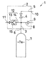
図1から図3は本発明の第1実施形態を示し、図1は逆止弁を備えたバルブ装置の系統図、図2はそのバルブ装置の一部破断面図、図3は逆止弁近傍の拡大断面図である。
【0013】
図1に示すように、このバルブ装置(1)は、ハウジング(2)に入口路(3)と閉止弁(4)と出口路(5)とを順に形成してあり、上記の入口路(3)は、入口穴(6)を介してガス容器(7)の内部空間(7a)に連通してある。また、この入口路(3)にはガス逃し路(8)が接続されており、このガス逃し路(8)に安全弁(9)が設けてある。上記の出口路(5)は、出口穴(10)を介して図示しないガス使用機器に接続され、上記の閉止弁(4)を開弁することにより、ガス容器(7)内の貯蔵ガスが消費される。
【0014】
上記の出口穴(10)は充填口(11)を兼ねており、上記の出口路(5)と入口路(3)との間に充填路(12)が、上記の閉止弁(4)と並列に形成してある。なお、上記の充填路(12)は、図1の仮想線に示すように、上記の入口路(3)に代えてガス容器(7)の内部空間(7a)へ直接連通させてもよい。
上記の充填路(12)は第1通路(13)と第2通路(14)とからなり、両通路(13・14)間に逆止弁(15)の弁室が設けてある。この逆止弁(15)は、出口路(5)側の第1通路(13)から入口路(3)側の第2通路(14)へのガスの流通は許容するが、第2通路(14)から第1通路(13)へのガスの流通は阻止する。そして、上記のガス容器(7)内へフレッシュガスを充填する際は、上記の出口穴(10)に図示しない充填装置が接続され、出口路(5)と充填路(12)と入口路(3)とを順に経てガス容器(7)の内部空間(7a)へフレッシュガスが充填される。
【0015】
次に、上記のバルブ装置の具体的な構造を、図1を参照しながら図2と図3に基づいて説明する。
図2に示すように、このバルブ装置(1)は、ハウジング(2)の下部に脚ネジ部(16)を備えており、この脚ネジ部(16)がガス容器(7)の首部(7b)に螺着固定される。この脚ネジ部(16)の下面にはガス容器(7)の内部空間(7a)に臨ませて前記の入口穴(6)が開口してある。一方、ハウジング(2)の側面にはノズル部(17)が突設してあり、このノズル部(17)の先端面に前記の出口穴(10)が開口してある。
【0016】
ハウジング(2)内には、上記の入口穴(6)と出口穴(10)との間に、前記の入口路(3)と閉止弁(4)の弁室(18)と出口路(5)とが順に形成してある。入口路(3)には前記のガス逃し路(8)が分岐してある。
上記の入口路(3)の上端は上記の閉止弁室(18)に開口してあり、この開口周縁に閉止弁座(19)が形成されている。
上記の閉止弁室(18)には閉止部材(20)が昇降自在に挿入されており、この閉止部材(20)はスピンドル(21)と操作ハンドル(22)により、上記の閉止弁座(19)に対し開閉操作される。
【0017】
上記のハウジング(2)には、上記のノズル部(17)とは異なる側面にボス部(23)を突設してあり、このボス部(23)に逆止弁装着孔(24)が形成してある。この装着孔(24)には蓋部材(25)がネジ止めされ、この装着孔(24)内に逆止弁(15)が設けてある。
即ち、図2及び図3に示すように、逆止弁(15)のハウジングの一部を構成する有底筒状のガイド筒(26)が、上記の装着孔(24)内にネジ止め固定されている。このガイド筒(26)の開口部と前記の閉止弁室(18)との間には前記の第1通路(13)が形成されている。また、このガイド筒(26)と上記の蓋部材(25)との間には連通空間(27)が形成され、この連通空間(27)と前記の入口路(3)との間に連通路(28)が形成してある。
【0018】
上記のガイド筒(26)内には逆止弁室(29)が形成してあり、この逆止弁室(29)に臨む上記の第1通路(13)の開口の周囲に逆止弁座(30)が形成してある。上記の逆止弁室(29)内には、逆止部材(31)が上記の逆止弁座(30)に対し進退自在に挿入してある。この逆止部材(31)の先端面には、上記の逆止弁座(30)へ接当する弁面(32)が形成してあり、この逆止部材(31)とガイド筒(26)の底壁(33)との間に、この逆止部材(31)を逆止弁座(30)側へ付勢する逆止バネ(34)が装着してある。また、上記の底壁(33)と逆止部材(31)との間には差圧室(35)が形成してあり、ガイド筒(26)の内周面には、開弁方向へ移動した逆止部材(31)を受止める受止め部(36)が形成してある。
【0019】
上記のガイド筒(26)の周壁には、上記の差圧室(35)と並列に、上記の逆止弁室(29)と前記の連通空間(27)とを連通する小径の連通路(37)が形成してある。前記の充填路(12)の一部を構成する第2通路(14)は、この小径連通路(37)と上記の連通空間(27)と前記の連通路(28)とにより形成される。
上記の差圧室(35)の周壁のうち、ガイド筒(26)の底壁(33)には連通孔(38)が透設してあり、この連通孔(38)を介して上記の差圧室(35)と上記の連通空間(27)とが連通してある。従って、この差圧室(35)と前記の逆止弁室(29)とは、上記の第2通路(14)のうちの上記の小径連通路(37)を経たのち、上記の連通孔(38)を介して連通される。
【0020】
次に、前記のガス容器内へフレッシュガスを充填する場合の、上記の逆止弁の作動について説明する。
最初に、前記の閉止弁(4)を閉じた状態で、前記のノズル部(17)にガス充填装置が接続され、フレッシュガスが出口穴(10)に供給される。これによりフレッシュガスは、出口路(5)から閉止弁室(18)を経て上記の第1通路(13)に流入し、そのガス圧で逆止部材(31)を逆止バネ(34)の付勢力に抗して開弁し、第2通路(14)から入口路(3)を経てガス容器(7)の内部空間(7a)へ充填される。
【0021】
このとき、上記の差圧室(35)は、第2通路(14)のうち逆止弁室(29)から離れた連通空間(27)に連通しており、この差圧室(35)内は、第1通路(13)内や逆止弁室(29)内と比べて低圧になっている。このため、上記の逆止部材(31)はこの差圧室(35)と逆止弁室(29)との差圧により、逆止バネ(34)の付勢力に抗して開弁側に付勢され、充填過程の終期近くになるまで、図3の上半部に示すように、前記の受止め部(36)に安定よく支持された開き位置(O)に保持される。この結果、ガス充填中の逆止部材(31)の振動が抑制され、音鳴りの発生が低減される。
【0022】
そして、充填過程の終期になると、上記の第1通路(13)内と第2通路(14)内の圧力差が少なくなり、従って、上記の逆止弁室(29)と第2通路(14)中の上記の連通空間(27)との圧力差も小さくなる。上記の差圧室(35)には、この連通空間(27)内の圧力が上記の連通孔(38)を介して作用している。この結果、この差圧室(35)内と逆止弁室(29)内との圧力差による開弁力が小さくなり、逆止部材(31)は、図3の下半部に示すように、上記の逆止バネ(34)に付勢されて逆止弁座(30)側の閉じ位置(S)へ移動し、閉弁する。
【0023】
上記の逆止部材(31)は、前記の従来技術のように、その周面に弁面を形成して閉弁時にこの弁面を上記の逆止弁座へ接当するように構成してもよい。しかし、この実施形態では、上記の逆止弁座(30)へ接当する弁面(32)を逆止部材(31)の先端面に形成してあるので、前記の従来技術と異なって、この弁面(32)を第1通路(13)内へ押し込む必要がない。このため、上記の逆止バネ(34)の付勢力を弱く設定でき、一層容易に、充填終期に至るまで逆止部材(31)を受止め部(36)に安定良く支持することができる。
また、上記の弁面(32)が逆止部材(31)の先端面に形成されることから、この弁面(32)と前記の逆止弁座(30)との間を充填ガス流が円滑に流れ易く、例えば充填ガス中の異物などによる弁面(32)の損傷を低減することができる。
【0024】
図4と図5は本発明の第2実施形態を示し、図4は逆止弁を備えたバルブ装置の一部破断面図、図5は逆止弁近傍の拡大断面図である。
この実施形態のバルブ装置は、系統図のうちの充填路が図1の仮想線で示すように形成されているが、その他の構成は上記の第1実施形態と同様である。
即ち、図4に示すように、バルブ装置(1)のハウジング(2)には脚ネジ部(16)の下面に逆止弁(15)が装着され、この逆止弁(15)と閉止弁室(18)との間に充填路(12)が形成されている。その他のバルブ装置の構成は、上記の第1実施形態と同様であるので、説明を省略する。
【0025】
図5に示すように、上記の逆止弁(15)のハウジング部分(2a)を構成する有底筒状のガイド筒(26)は、開口部を上方に向けて脚ネジ部(16)の下面に螺着固定してある。ガイド筒(26)の開口部内には逆止弁室(29)が形成され、上記の充填路(12)の下端開口はこの逆止弁室(29)に臨ませてあり、この充填路(12)が逆止弁(15)の第1通路(13)を構成している。
上記の第1通路(13)の下端開口の周囲には逆止弁座(30)が形成してあり、逆止弁室(29)に挿入された逆止部材(31)が逆止バネ(34)で逆止弁座(30)側へ付勢してある。
【0026】
上記のガイド筒(26)の底壁(33)と逆止部材(31)との間には差圧室(35)が形成してあり、ガイド筒(26)の内周面には、開弁方向へ移動した開き位置(O)の逆止部材(31)を受止める受止め部(36)が形成してある。
上記のガイド筒(26)の周壁には、前記の逆止弁室(29)とガス容器(7)の内部空間(7a)とを連通する第2通路(14)が形成してある。
上記の差圧室(35)の周壁のうち、上記のガイド筒(26)の底壁(33)には連通孔(38)が透設してあり、上記の差圧室(35)は、この連通孔(38)と上記の内部空間(7a)と第2通路(14)とを順に介して上記の逆止弁室(29)に連通してある。
【0027】
上記の差圧室(35)内には、ガス容器(7)の内部空間(7a)の圧力が作用するが、この内部空間(7a)は第2通路(14)を介して逆止弁室(29)に連通している。このため、逆止弁室(29)と差圧室(35)との間には、充填過程の終期に達するまで比較的大きな圧力差を生じるので、この逆止弁(15)は前記の第1実施形態と同様に作用する。
【0028】
上記の実施形態ではいずれも充填口を出口穴と兼用したバルブ装置について説明した。しかし本発明は出口穴と別に充填口を設けたバルブ装置にも適用することができる。
即ち、図6から図8はこの場合の第3実施形態を示し、図6は逆止弁を備えたバルブ装置の系統図、図7はそのバルブ装置の一部破断面図、図8は逆止弁近傍の拡大断面図である。
【0029】
図6に示すように、このバルブ装置(1)のハウジング(2)には、前記の第1実施形態と異なって、充填口(11)が上記の出口穴(10)とは別に設けてあり、この充填口(11)と上記の入口路(3)との間に充填路(12)が形成してある。なお、この充填路(12)は上記の入口路(3)に代えてガス容器(7)の内部空間(7a)へ直接連通させてもよい。さらに、前記の出口路(5)に流量調整弁を設けた場合などは、この流量調整弁と前記の閉止弁(4)との間の出口路(5)と、上記の充填口(11)との間に充填路(12)を形成してもよい。
上記の充填路(12)は、充填口(11)側の第1通路(13)と入口路(3)側の第2通路(14)とからなり、両通路(13・14)間に逆止弁(15)の弁室が設けてある。その他の構成は前記の第1実施形態と同様であるので、説明を省略する。
【0030】
次に、上記のバルブ装置の具体的な構造を、図6を参照しながら図7と図8に基づいて説明する。
図7に示すように、このバルブ装置(1)は、前記の第1実施形態と同様、脚ネジ部(16)の下面に入口穴(6)が開口してある。また、ハウジング(2)の側面に突設したノズル部(17)に出口穴(10)を開口してあり、前記の入口穴(6)とこの出口穴(10)との間に、入口路(3)と閉止弁(4)の弁室(18)と出口路(5)とが順に形成してある。
【0031】
上記のハウジング(2)の側面には前記のノズル部(17)とは異なる側面にボス部(23)を突設して、このボス部(23)に逆止弁装着孔(24)が形成してある。この装着孔(24)には、筒部材(39)とこれに螺着固定したガイド筒(26)がネジ止めされ、この筒部材(39)とガイド筒(26)とが逆止弁(15)のハウジング部分(2a)を構成している。上記の装着孔(24)の開口に充填口(11)が形成され、この充填口(11)と前記の入口路(3)との間に、上記のガイド筒(26)内を通過する充填路(12)が形成されている。
【0032】
上記の筒部材(39)内には、前記のガイド筒(26)の開口部と上記の充填口(11)との間に第1通路(13)が形成されている。また、ガイド筒(26)と上記の入口路(3)との間には連通路(28)が形成してある。
【0033】
図7と図8に示すように、上記のガイド筒(26)内には、前記の第1実施形態と同様、逆止弁室(29)が形成してあり、この逆止弁室(29)に臨む上記の第1通路(13)の開口の周囲に逆止弁座(30)が形成され、逆止弁室(29)内には、逆止部材(31)が上記の逆止弁座(30)に対し進退自在に挿入してある。上記のガイド筒(26)の底壁(33)と上記の逆止部材(31)との間には差圧室(35)が形成してある。
【0034】
上記のガイド筒(26)の周壁には、上記の差圧室(35)と並列に、前記の逆止弁室(29)と連通路(28)とを連通する小径の連通路(37)が形成してある。前記の充填路(12)の一部を構成する第2通路(14)は、この小径連通路(37)と上記の連通路(28)とにより形成される。上記の差圧室(35)の周壁のうち、上記のガイド筒(26)の底壁(33)には連通孔(38)が透設してあり、この連通孔(38)を介して上記の差圧室(35)と上記の連通路(28)とが連通してある。従って、この差圧室(35)と前記の逆止弁室(29)とは、前記の第1実施形態と同様、上記の第2通路(14)のうちの上記の小径連通路(37)を経たのち、上記の連通孔(38)を介して連通される。
その他の構成は前記の第1実施形態と同様であり、同様に作用するので説明を省略する。
【0035】
上記の逆止弁室(29)は、例えば図9に示す変形例のように、ガイド筒(26)の内面に形成した環状凹部(40)で構成してもよい。この場合は、この環状凹部(40)からガイド筒(26)の端面まで前記の小径連通路(37)を直線状に加工すればよく、容易に形成することができる。
【0036】
図10は本発明の第4実施形態を示し、上半部は閉弁状態の、下半部は開弁状態の、逆止弁の拡大断面図である。
この第4実施形態では、バルブ装置のハウジング(2)の外面のうち、出口穴とは異なる位置に充填ノズル部(41)を設けて、この充填ノズル部(41)に逆止弁装着孔(24)を形成し、この装着孔(24)に逆止弁(15)のハウジング部分(2a)を構成する筒部材(39)とこれに螺着固定したガイド筒(26)がネジ止めされている。
【0037】
上記の筒部材(39)内には、上記の第3実施形態と同様、前記のガイド筒(26)の開口部と充填ノズル部(41)の先端に開口した充填口(11)との間に第1通路(13)が形成されている。また、ガイド筒(26)と図外の入口路との間に連通路(28)が形成してある。さらに、上記のガイド筒(26)内には逆止弁室(29)が形成してあり、この逆止弁室(29)に臨む上記の第1通路(13)の開口の周囲に逆止弁座(30)が形成してある。
【0038】
上記の逆止弁室(29)の内周面にはガイド面(42)が形成され、この逆止弁室(29)に挿入した逆止部材(31)を、上記の逆止弁座(30)に対して進退自在に上記のガイド面(42)で支持してある。そして、上記のガイド筒(26)の底壁(33)と上記の逆止部材(31)との間に差圧室(35)が形成してある。
【0039】
上記の差圧室(35)の周囲には環状凹部(40)が形成してあり、この環状凹部(40)と上記の逆止弁室(29)とは、ガイド面(42)と逆止部材(31)との間の狭い間隙を介して連通してある。また、上記の環状凹部(40)と前記の連通路(28)との間には小径の連通路(37)が形成してあり、この小径連通路(37)と上記の連通路(28)とにより第2通路(14)が構成される。上記の差圧室(35)の周壁のうち、上記のガイド筒(26)の底壁(33)には連通孔(38)が透設してあり、この連通孔(38)を介して上記の第2通路(14)の一部である連通路(28)と上記の差圧室(35)とが連通している。従って、上記の逆止弁室(29)と上記の差圧室(35)とは、上記のガイド面(42)と逆止部材(31)との間の狭い間隙と、上記の環状凹部(40)と、上記の第2通路(14)と、上記の連通孔(38)とを順に介して連通している。
【0040】
上記の逆止弁は次のように作動する。
充填ノズル(41)にガス充填装置が接続され、フレッシュガスが充填口(11)から上記の第1通路(13)に流入すると、その充填ガス圧により逆止部材(31)が逆止バネ(34)の付勢力に抗して開弁移動する。これにより、フレッシュガスは上記のガイド面(42)と逆止部材(31)との間の狭い間隙と、上記の環状凹部(40)と、上記の第2通路(14)とを順に経て図外のガス容器内へ案内される。
【0041】
このとき、上記の差圧室(35)は、上記のガイド面(42)と逆止部材(31)との間の狭い間隙を介して逆止弁室(29)に連通していることから、この差圧室(35)内は第1通路(13)内や逆止弁室(29)内と比べて低圧になっている。このため、上記の逆止部材(31)はこの差圧室(35)と逆止弁室(29)との差圧により、逆止バネ(34)の付勢力に抗して開弁側に付勢され、充填過程の終期近くになるまで、図10の下半部に示すように受止め部(36)に安定よく支持された開き位置(O)に保持される。この結果、ガス充填中の逆止部材(31)の振動が抑制され、音鳴りの発生が低減される。
【0042】
充填過程の終期になると、上記の第1通路(13)内と第2通路(14)内の圧力差が少なくなり、従って、この第2通路(14)内の圧力が作用する差圧室(35)と上記の逆止弁室(29)との圧力差も小さくなる。このため、この圧力差による開弁力が小さくなり、上記の逆止バネ(34)の閉弁力により、図10の上半部に示すように逆止部材(31)が逆止弁座(30)側の閉じ位置(S)へ移動し、閉弁する。
【0043】
その他の構成は前記の第3実施形態と同様であり、同様に作用するので説明を省略する。
なお、この第4実施形態では、上記の第3実施形態と同様、出口穴とは別に充填口を形成したバルブ装置に適用する場合について説明したが、この第4実施形態のものを、前記の第1実施形態のように、出口穴と充填口とを兼用する場合のバルブ装置に適用することも可能である。
【0044】
また、上記の第1通路や第2通路、逆止部材、付勢手段、ハウジングなど、本発明の逆止弁の具体的な構造は、上記の各実施形態で説明した構造のものに限定されず、さらに本発明の逆止弁は、充填路以外の流路に設けてもよいことは言うまでもない。
【0045】
【発明の効果】
本発明は上記のように構成され作用することから、次の効果を奏する。
【0046】
(1) 例えば充填過程において、第1通路内と逆止弁室内との差圧が早期に小さくなっても、上記の差圧室と第1通路や逆止弁室内との差圧は、充填過程の終期近くになるまで大きく保たれるので、上記の逆止部材は、上記の受止め部に安定よく支持された開き位置に保持される。この結果、ガス流通時の逆止部材の振動が抑制され、音鳴りの発生を低減することができる。
【0047】
(2) また、逆止部材が、開き位置と閉じ位置の中間に位置することが少ないので、逆止部材の弁面が高速で流れるガス流中に露出されることが低減され、弁面やシール部材等の損傷を防止することができる。
【0048】
(3) 上記の逆止部材の先端面に、上記の逆止弁座へ接当する弁面を形成した場合には、付勢手段の付勢力を小さく設定できるので、逆止部材を一層良好に上記の受止め部へ安定良く支持できるうえ、開弁時にガス流がこの弁面に沿って円滑に流れ易いことから、例えばガス中の異物などによる弁面の損傷を低減することができる。
【図面の簡単な説明】
【図1】本発明の第1実施形態を示す、逆止弁を備えたバルブ装置の系統図である。
【図2】第1実施形態の、逆止弁を備えたバルブ装置の一部破断面図である。
【図3】第1実施形態を示し、上半部は開弁状態の、下半部は閉弁状態の、逆止弁近傍の拡大断面図である。
【図4】本発明の第2実施形態を示す、逆止弁を備えたバルブ装置の一部破断面図である。
【図5】第2実施形態を示し、左半部は閉弁状態の、右半部は開弁状態の、逆止弁近傍の拡大断面図である。
【図6】本発明の第3実施形態を示す、逆止弁を備えたバルブ装置の系統図である。
【図7】第3実施形態の、逆止弁を備えたバルブ装置の一部破断面図である。
【図8】第3実施形態を示し、上半部は開弁状態の、下半部は閉弁状態の、逆止弁近傍の拡大断面図である。
【図9】第3実施形態の変形例を示し、上半部は閉弁状態の、下半部は開弁状態の、逆止弁の断面図である。
【図10】本発明の第4実施形態を示し、上半部は閉弁状態の、下半部は開弁状態の、逆止弁の断面図である。
【図11】従来技術を示し、上半部は閉弁状態の、下半部は開弁状態の、逆止弁の断面図である。
【符号の説明】
13…第1通路
14…第2通路
15…逆止弁
29…逆止弁室
30…逆止弁座
31…逆止部材
32…弁面
33…差圧室の周壁(ガイド筒の底壁)
34…付勢手段(逆止バネ)
35…差圧室
36…受止め部
38…連通孔
42…ガイド面[0001]
TECHNICAL FIELD OF THE INVENTION
The present invention relates to a check valve provided in a filling passage or the like of a valve device, and more particularly, to a check valve that suppresses vibration of a check member during gas flow and reduces generation of noise.
[0002]
[Prior art]
In a valve device having a gas taking-out path and a filling path, a check valve is normally provided in the filling path to shut off the flow from the internal space of the gas container to the filling port.
Conventionally, as the above-mentioned check valve, there is, for example, one shown in FIG. That is, the check valve (50) is formed with a first passage (52), a check valve chamber (53), and a second passage (54) in the housing (51) in order, and the check valve chamber (53). A check valve seat (55) is formed at the open end of the first passageway (52) that opens to the side, and a check member (56) is provided in the check valve chamber (53) and the check valve seat (55). ), The check member (56) is urged in a valve closing direction by a check spring (57) to move the check member (56) from the first passage (52) to the second passage (54). Although the gas is allowed to flow, the gas is prevented from flowing from the second passage (54) to the first passage (52). A receiving portion (58) for receiving the check member (56) moved in the valve opening direction is formed in the housing (51), and the check valve is sandwiched between the check member (56). A differential pressure chamber (59) is formed on the side opposite to the seat (55), and the differential pressure chamber (59) communicates with the check valve chamber (53).
[0003]
[Problems to be solved by the invention]
When the pressure inside the first passage (52) becomes high due to the filling gas pressure, the check member (56) opens due to the pressure difference between the inside of the differential pressure chamber (59) and the inside of the first passage (52). The valve closes when the valve opening force due to the differential pressure with the differential pressure chamber (59) becomes smaller than the valve closing force of the check spring (57).
At this time, in the initial stage of the filling process, the valve opening force due to the differential pressure between the first passage (52) and the differential pressure chamber (59) is large, and the valve opening force of the check spring (57) is reduced. Then, the check member (56) moves to open the valve, and the check member (56) at the open position (O) is received by the receiving portion (58), and is stably supported.
[0004]
However, since the internal pressure of the differential pressure chamber (59) is in communication with the check valve chamber (53), the inside of the first passage (52) and the differential pressure chamber (59) are relatively early in the filling process. 59), the check member (56) shifts to an intermediate position between the open position (O) and the closed position (S). At this intermediate position, the check member (56) is in an unstable state supported only by the check spring (57), and the flow of the filling gas is disturbed. There is a problem that a sound is generated due to easy vibration and contact with and separation from a surrounding guide surface.
[0005]
At this time, when the valve is closed, the tip of the check member (56) projects into the first passage (52) so that the peripheral surface of the check member (56) contacts the check valve seat (55). In this case, the urging force of the check spring (57) needs to be set large so that the valve is securely closed, and the check member (56) is moved to the intermediate position even earlier. Migrate easily and become unstable.
[0006]
In order to suppress the above-described vibration, for example, as shown in FIG. 11, an O-ring (60) may be attached to the outer peripheral surface of the check member (56) to buffer the contact with and separation from the guide surface. However, if foreign matter such as fine dust accumulates on the O-ring (60), the sliding resistance increases, and the check member (56) may not be able to properly close the valve.
[0007]
When the check member (56) is at the intermediate position, the seal member (61) attached to the tip of the check member (56) is exposed to the gas flow flowing at a high speed. The seal member (61) may be damaged at an early stage.
SUMMARY OF THE INVENTION It is a technical object of the present invention to solve the above-mentioned problems and to provide a check valve which suppresses vibration of a check member during gas flow and reduces generation of noise.
[0008]
[Means for Solving the Problems]
In order to solve the above-described problems, the present invention will be described with reference to, for example, FIGS. 1 to 10 showing an embodiment of the present invention, in which a check valve is configured as follows.
That is, according to the first aspect of the present invention, the first passage (13), the check valve chamber (29), and the second passage (14) are formed in this order, and the check valve chamber (29) is reversed. A check valve seat (30) is formed, and a check member (31) is inserted into the check valve chamber (29) so as to advance and retreat with respect to the check valve seat (30). The member (31) is urged in the valve closing direction by the urging means (34) to allow the gas to flow from the first passage (13) to the second passage (14), but the second passage (14). A check valve configured to prevent gas from flowing from the first passage (13) to the first passage (13),
A receiving portion (36) for receiving the check member (31) moved in the valve-opening direction is provided, and the check member (31) is sandwiched between the check member and the check valve seat (30) on the side opposite to the check valve seat (30). A pressure chamber (35) is formed, a communication hole (38) is formed in the peripheral wall (33) of the differential pressure chamber (35), and the differential pressure chamber (35) is inserted through the communication hole (38). ) Is communicated with a portion of the second passage (14) remote from the check valve chamber (29).
[0009]
According to a second aspect of the present invention, the first passage (13), the check valve chamber (29), and the second passage (14) are formed in this order, and the check valve chamber (29) is reversed. A check valve seat (30) is formed, a guide surface (42) is formed on the inner peripheral surface of the check valve chamber (29), and a check member (31) is inserted into the check valve chamber (29). Then, the check member (31) is supported on the guide surface (42) so as to be able to advance and retreat with respect to the check valve seat (30), and the check member (31) is biased. The gas is urged in the valve closing direction at (34) to allow the gas to flow from the first passage (13) to the second passage (14), but from the second passage (14) to the first passage (13). A check valve configured to block the flow of gas of
A receiving portion (36) for receiving the check member (31) moved in the valve-opening direction is provided, and the check member (31) is sandwiched between the check member and the check valve seat (30) on the side opposite to the check valve seat (30). A pressure chamber (35) is formed, a communication hole (38) is formed through the peripheral wall (33) of the differential pressure chamber (35), and the check valve chamber (29) is connected to the second passage (14). ) Is communicated through a narrow gap between the guide surface (42) and the check member (31), and the second passage (14) is connected to the differential pressure chamber (35). It is characterized in that it is communicated through the communication hole (38).
[0010]
[Action]
According to the first aspect of the present invention, since the differential pressure chamber is communicated with a portion of the second passage remote from the check valve chamber, the differential pressure chamber is in the first passage or the check valve chamber. The pressure is lower than that of. According to the second aspect of the present invention, the check valve chamber and the second passage are communicated with each other through a narrow gap between the guide surface and the check member, and the second passage is connected to the difference passage. Since the differential pressure chamber is in communication with the pressure chamber, the pressure in the differential pressure chamber is lower than that in the first passage and the check valve chamber.
For this reason, even if the differential pressure between the first passage and the check valve chamber is reduced, the differential pressure between the differential pressure chamber and the first passage or the check valve chamber is kept large. The stop member is held in an open position that is stably supported by the receiving part, for example, until near the end of the filling process.
[0011]
When the pressure difference between the first passage and the second passage is reduced, the pressure in the second passage acts on the differential pressure chamber through the communication hole. The valve opening force due to the pressure difference between the valve and the first passage is reduced, and the check member is moved to the check valve seat side by the valve closing force of the urging means to close the valve.
[0012]
BEST MODE FOR CARRYING OUT THE INVENTION
1 to 3 show a first embodiment of the present invention. FIG. 1 is a system diagram of a valve device provided with a check valve, FIG. 2 is a partially cutaway sectional view of the valve device, and FIG. It is an expanded sectional view of a vicinity.
[0013]
As shown in FIG. 1, in the valve device (1), an inlet path (3), a shut-off valve (4), and an outlet path (5) are sequentially formed in a housing (2). 3) communicates with the internal space (7a) of the gas container (7) via the inlet hole (6). A gas relief path (8) is connected to the inlet path (3), and a safety valve (9) is provided in the gas relief path (8). The outlet passage (5) is connected to a gas-using device (not shown) through an outlet hole (10), and the stored gas in the gas container (7) is opened by opening the shut-off valve (4). Consumed.
[0014]
The outlet hole (10) also serves as a filling port (11), and a filling path (12) is provided between the outlet path (5) and the inlet path (3). They are formed in parallel. In addition, as shown by the imaginary line in FIG. 1, the filling path (12) may be directly connected to the internal space (7a) of the gas container (7) instead of the entrance path (3).
The filling passage (12) includes a first passage (13) and a second passage (14), and a valve chamber of a check valve (15) is provided between the two passages (13, 14). The check valve (15) allows the gas to flow from the first passage (13) on the outlet passage (5) side to the second passage (14) on the inlet passage (3) side. Gas flow from 14) to the first passage (13) is blocked. When filling the gas container (7) with fresh gas, a filling device (not shown) is connected to the outlet hole (10), and the outlet passage (5), the filling passage (12), and the inlet passage ( 3), the inner space (7a) of the gas container (7) is filled with fresh gas.
[0015]
Next, a specific structure of the above-described valve device will be described based on FIGS. 2 and 3 with reference to FIG.
As shown in FIG. 2, the valve device (1) includes a leg screw (16) at a lower portion of the housing (2), and the leg screw (16) is attached to a neck (7b) of the gas container (7). ). The inlet hole (6) is opened on the lower surface of the leg screw portion (16) so as to face the internal space (7a) of the gas container (7). On the other hand, a nozzle portion (17) protrudes from a side surface of the housing (2), and the outlet hole (10) is opened at a tip end surface of the nozzle portion (17).
[0016]
In the housing (2), the inlet passage (3), the valve chamber (18) of the shut-off valve (4) and the outlet passage (5) are provided between the inlet hole (6) and the outlet hole (10). ) Are formed in order. The gas release path (8) branches off from the inlet path (3).
The upper end of the inlet passage (3) is open to the above-mentioned closing valve chamber (18), and a closing valve seat (19) is formed around the opening.
A shut-off member (20) is inserted into the shut-off valve chamber (18) so as to be able to move up and down, and the shut-off member (20) is moved by the spindle (21) and the operating handle (22). ).
[0017]
The housing (2) has a boss (23) projecting from a side surface different from the nozzle (17), and a check valve mounting hole (24) is formed in the boss (23). I have. A lid member (25) is screwed into the mounting hole (24), and a check valve (15) is provided in the mounting hole (24).
That is, as shown in FIGS. 2 and 3, a bottomed cylindrical guide tube (26) constituting a part of the housing of the check valve (15) is screwed and fixed in the mounting hole (24). Have been. The first passage (13) is formed between the opening of the guide cylinder (26) and the closing valve chamber (18). A communication space (27) is formed between the guide tube (26) and the lid member (25), and a communication passage is provided between the communication space (27) and the entrance path (3). (28) is formed.
[0018]
A check valve chamber (29) is formed in the guide cylinder (26), and a check valve seat is formed around the opening of the first passage (13) facing the check valve chamber (29). (30) is formed. A check member (31) is inserted into the check valve chamber (29) so as to be able to advance and retreat with respect to the check valve seat (30). A valve surface (32) for contacting the check valve seat (30) is formed on a distal end surface of the check member (31), and the check member (31) and the guide cylinder (26) are formed. A check spring (34) for urging the check member (31) toward the check valve seat (30) is mounted between the check valve and the bottom wall (33). Further, a differential pressure chamber (35) is formed between the bottom wall (33) and the check member (31), and the inner peripheral surface of the guide cylinder (26) moves in the valve opening direction. A receiving portion (36) for receiving the check member (31) is formed.
[0019]
In the peripheral wall of the guide cylinder (26), in parallel with the differential pressure chamber (35), a small-diameter communication passage (27) that communicates the check valve chamber (29) with the communication space (27). 37) is formed. The second passage (14) constituting a part of the filling passage (12) is formed by the small-diameter communication passage (37), the communication space (27), and the communication passage (28).
In the peripheral wall of the differential pressure chamber (35), a communication hole (38) is formed through the bottom wall (33) of the guide cylinder (26), and the differential pressure is reduced through the communication hole (38). The pressure chamber (35) communicates with the communication space (27). Therefore, the differential pressure chamber (35) and the check valve chamber (29) pass through the small-diameter communication passage (37) of the second passage (14), and then pass through the communication hole ( 38).
[0020]
Next, the operation of the above-described check valve when the above-mentioned gas container is filled with fresh gas will be described.
First, with the closing valve (4) closed, a gas filling device is connected to the nozzle portion (17), and fresh gas is supplied to the outlet hole (10). As a result, the fresh gas flows from the outlet passage (5) through the shut-off valve chamber (18) into the first passage (13), and the gas pressure causes the check member (31) to move to the check spring (34). The valve is opened against the urging force, and the internal space (7a) of the gas container (7) is filled from the second passage (14) through the inlet passage (3).
[0021]
At this time, the differential pressure chamber (35) communicates with a communication space (27) of the second passage (14) that is separated from the check valve chamber (29), and inside the differential pressure chamber (35). Is lower in pressure than in the first passage (13) and in the check valve chamber (29). Therefore, the check member (31) moves toward the valve opening side against the urging force of the check spring (34) due to the differential pressure between the differential pressure chamber (35) and the check valve chamber (29). Until near the end of the filling process, as shown in the upper half of FIG. 3, it is held in the open position (O), which is stably supported by the receiving part (36). As a result, the vibration of the check member (31) during gas filling is suppressed, and the generation of noise is reduced.
[0022]
Then, at the end of the filling process, the pressure difference between the first passage (13) and the second passage (14) decreases, and therefore, the check valve chamber (29) and the second passage (14). The pressure difference between the communication space (27) and the above-mentioned communication space (27) also becomes small. The pressure in the communication space (27) acts on the differential pressure chamber (35) via the communication hole (38). As a result, the valve opening force due to the pressure difference between the differential pressure chamber (35) and the check valve chamber (29) is reduced, and the check member (31) is, as shown in the lower half of FIG. The spring is biased by the check spring (34) and moves to the close position (S) on the check valve seat (30) side to close the valve.
[0023]
The check member (31) is configured such that a valve surface is formed on a peripheral surface thereof and the valve surface is brought into contact with the check valve seat when the valve is closed, as in the above-described conventional technology. Is also good. However, in this embodiment, since the valve surface (32) contacting the above-mentioned check valve seat (30) is formed on the distal end surface of the check member (31), unlike the above-mentioned prior art, There is no need to push this valve face (32) into the first passage (13). Therefore, the urging force of the check spring (34) can be set to be weak, and the check member (31) can be more stably supported on the receiving portion (36) until the end of filling.
Further, since the valve surface (32) is formed on the distal end surface of the check member (31), the filling gas flow flows between the valve surface (32) and the check valve seat (30). It is easy to flow smoothly, and it is possible to reduce damage to the valve surface (32) due to, for example, foreign matter in the filling gas.
[0024]
4 and 5 show a second embodiment of the present invention. FIG. 4 is a partially broken sectional view of a valve device provided with a check valve, and FIG. 5 is an enlarged sectional view of the vicinity of the check valve.
In the valve device of this embodiment, the filling path in the system diagram is formed as shown by the imaginary line in FIG. 1, but other configurations are the same as those of the above-described first embodiment.
That is, as shown in FIG. 4, a check valve (15) is mounted on the lower surface of the leg screw (16) on the housing (2) of the valve device (1), and the check valve (15) and the shut-off valve are provided. A filling path (12) is formed between the chamber and the chamber (18). The other configuration of the valve device is the same as that of the above-described first embodiment, and the description is omitted.
[0025]
As shown in FIG. 5, the bottomed cylindrical guide tube (26) constituting the housing portion (2a) of the check valve (15) has a leg screw portion (16) with an opening directed upward. It is screwed and fixed to the lower surface. A check valve chamber (29) is formed in the opening of the guide cylinder (26), and the lower end opening of the filling path (12) faces the check valve chamber (29). 12) constitutes a first passage (13) of the check valve (15).
A check valve seat (30) is formed around the lower end opening of the first passage (13), and a check member (31) inserted into the check valve chamber (29) includes a check spring ( At 34), it is urged toward the check valve seat (30).
[0026]
A differential pressure chamber (35) is formed between the bottom wall (33) of the guide cylinder (26) and the check member (31), and an inner peripheral surface of the guide cylinder (26) is opened. A receiving portion (36) for receiving the check member (31) at the open position (O) moved in the valve direction is formed.
A second passageway (14) is formed in a peripheral wall of the guide cylinder (26) to communicate the check valve chamber (29) with the internal space (7a) of the gas container (7).
In the peripheral wall of the differential pressure chamber (35), a communication hole (38) is provided through the bottom wall (33) of the guide cylinder (26), and the differential pressure chamber (35) The communication hole (38), the internal space (7a), and the second passage (14) sequentially communicate with the check valve chamber (29).
[0027]
The pressure of the internal space (7a) of the gas container (7) acts on the differential pressure chamber (35), and the internal space (7a) is connected to the check valve chamber via the second passage (14). (29). As a result, a relatively large pressure difference is generated between the check valve chamber (29) and the differential pressure chamber (35) until the end of the filling process, so that the check valve (15) is It works in the same way as the first embodiment.
[0028]
In the above embodiments, the valve device in which the filling port also serves as the outlet hole has been described. However, the present invention can also be applied to a valve device provided with a filling port separately from the outlet hole.
6 to 8 show a third embodiment in this case, FIG. 6 is a system diagram of a valve device provided with a check valve, FIG. 7 is a partially broken sectional view of the valve device, and FIG. It is an expanded sectional view near a stop valve.
[0029]
As shown in FIG. 6, unlike the first embodiment, the housing (2) of the valve device (1) has a filling port (11) provided separately from the outlet hole (10). A filling path (12) is formed between the filling port (11) and the inlet path (3). The filling path (12) may be directly connected to the internal space (7a) of the gas container (7) instead of the inlet path (3). Further, when a flow control valve is provided in the outlet path (5), the outlet path (5) between the flow control valve and the shut-off valve (4) and the filling port (11). And a filling path (12) may be formed between them.
The filling path (12) is composed of a first passage (13) on the filling port (11) side and a second passage (14) on the inlet path (3) side. A valve chamber for the stop valve (15) is provided. The other configuration is the same as that of the first embodiment, and the description is omitted.
[0030]
Next, a specific structure of the above-described valve device will be described based on FIGS. 7 and 8 with reference to FIG.
As shown in FIG. 7, this valve device (1) has an inlet hole (6) opened in the lower surface of the leg screw portion (16), as in the first embodiment. An outlet hole (10) is opened in a nozzle portion (17) protruding from a side surface of the housing (2), and an inlet passage is provided between the inlet hole (6) and the outlet hole (10). (3), a valve chamber (18) of the closing valve (4) and an outlet path (5) are formed in order.
[0031]
A boss (23) protrudes from a side of the housing (2) different from the nozzle (17), and a check valve mounting hole (24) is formed in the boss (23). I have. A cylinder member (39) and a guide cylinder (26) screwed and fixed to the cylinder member (39) are screwed into the mounting hole (24), and the cylinder member (39) and the guide cylinder (26) are connected to the check valve (15). ) Of the housing portion (2a). A filling port (11) is formed at the opening of the mounting hole (24), and a filling port passing through the guide tube (26) is provided between the filling port (11) and the entrance path (3). A path (12) is formed.
[0032]
A first passage (13) is formed in the cylindrical member (39) between the opening of the guide cylinder (26) and the filling port (11). A communication path (28) is formed between the guide cylinder (26) and the above-mentioned entrance path (3).
[0033]
As shown in FIGS. 7 and 8, a check valve chamber (29) is formed in the guide cylinder (26) as in the first embodiment, and the check valve chamber (29) is formed. ), A check valve seat (30) is formed around the opening of the first passage (13), and a check member (31) is provided in the check valve chamber (29). It is inserted into the seat (30) so as to be able to move forward and backward. A differential pressure chamber (35) is formed between the bottom wall (33) of the guide tube (26) and the check member (31).
[0034]
A small-diameter communication passage (37) communicating with the check valve chamber (29) and the communication passage (28) is provided on a peripheral wall of the guide cylinder (26) in parallel with the differential pressure chamber (35). Is formed. The second passage (14) constituting a part of the filling passage (12) is formed by the small-diameter communication passage (37) and the communication passage (28). In the peripheral wall of the differential pressure chamber (35), a communication hole (38) is provided through the bottom wall (33) of the guide tube (26), and the communication hole (38) is inserted through the communication hole (38). The pressure difference chamber (35) communicates with the communication passage (28). Accordingly, the differential pressure chamber (35) and the check valve chamber (29) are connected to the small-diameter communication passage (37) of the second passage (14), similarly to the first embodiment. After that, it is communicated through the communication hole (38).
The other configuration is the same as that of the above-described first embodiment.
[0035]
The above-described check valve chamber (29) may be constituted by an annular concave portion (40) formed on the inner surface of the guide cylinder (26), for example, as in a modified example shown in FIG. In this case, the small-diameter communication passage (37) may be formed linearly from the annular concave portion (40) to the end face of the guide cylinder (26), and can be easily formed.
[0036]
FIG. 10 is an enlarged sectional view of a check valve according to a fourth embodiment of the present invention, in which the upper half is in a closed state and the lower half is in an open state.
In the fourth embodiment, a filling nozzle portion (41) is provided at a position different from the outlet hole in the outer surface of the housing (2) of the valve device, and the check nozzle mounting hole (41) is provided in the filling nozzle portion (41). 24), and a cylindrical member (39) constituting a housing part (2a) of the check valve (15) and a guide cylinder (26) screwed to the cylindrical member (39) are screwed into the mounting hole (24). I have.
[0037]
In the cylindrical member (39), between the opening of the guide cylinder (26) and the filling port (11) opened at the tip of the filling nozzle (41), as in the third embodiment. A first passage (13) is formed in the first passage. A communication passage (28) is formed between the guide cylinder (26) and an entrance passage (not shown). Further, a check valve chamber (29) is formed in the guide cylinder (26), and a check valve is formed around the opening of the first passage (13) facing the check valve chamber (29). A valve seat (30) is formed.
[0038]
A guide surface (42) is formed on the inner peripheral surface of the check valve chamber (29), and the check member (31) inserted into the check valve chamber (29) is connected to the check valve seat (29). 30) is supported on the guide surface (42) so as to be able to advance and retreat with respect to 30). A differential pressure chamber (35) is formed between the bottom wall (33) of the guide cylinder (26) and the check member (31).
[0039]
An annular concave portion (40) is formed around the differential pressure chamber (35), and the annular concave portion (40) and the check valve chamber (29) are in check with the guide surface (42). It communicates with the member (31) via a narrow gap. A small-diameter communication path (37) is formed between the annular recess (40) and the communication path (28), and the small-diameter communication path (37) and the communication path (28) are formed. A second passage (14) is configured by the above. In the peripheral wall of the differential pressure chamber (35), a communication hole (38) is provided through the bottom wall (33) of the guide tube (26), and the communication hole (38) is inserted through the communication hole (38). The communication passage (28), which is a part of the second passage (14), communicates with the differential pressure chamber (35). Therefore, the check valve chamber (29) and the differential pressure chamber (35) are provided with a narrow gap between the guide surface (42) and the check member (31) and the annular concave portion (31). 40), the second passage (14), and the communication hole (38) in this order.
[0040]
The above check valve operates as follows.
When a gas filling device is connected to the filling nozzle (41) and fresh gas flows into the first passage (13) from the filling port (11), the check gas (31) causes the check member (31) to move the check spring ( The valve opens and moves against the biasing force of 34). Thereby, the fresh gas flows through the narrow gap between the guide surface (42) and the check member (31), the annular recess (40), and the second passage (14) in this order. Guided into the outer gas container.
[0041]
At this time, the differential pressure chamber (35) communicates with the check valve chamber (29) via a narrow gap between the guide surface (42) and the check member (31). The pressure in the differential pressure chamber (35) is lower than that in the first passage (13) and the inside of the check valve chamber (29). Therefore, the check member (31) moves toward the valve opening side against the urging force of the check spring (34) due to the differential pressure between the differential pressure chamber (35) and the check valve chamber (29). It is biased and held in the open position (O) which is stably supported by the receiving part (36) as shown in the lower half of FIG. 10 until near the end of the filling process. As a result, the vibration of the check member (31) during gas filling is suppressed, and the generation of noise is reduced.
[0042]
At the end of the filling process, the pressure difference between the first passage (13) and the second passage (14) decreases, and therefore, the differential pressure chamber () in which the pressure in the second passage (14) acts. The pressure difference between 35) and the check valve chamber (29) also becomes small. For this reason, the valve opening force due to this pressure difference is reduced, and the check member (31) causes the check member (31) to move the check valve seat (31) as shown in the upper half of FIG. Move to the 30) side close position (S) and close the valve.
[0043]
The other configuration is the same as that of the third embodiment described above, and operates in the same manner.
In the fourth embodiment, similarly to the third embodiment described above, a case where the present invention is applied to a valve device in which a filling port is formed separately from an outlet hole has been described. As in the first embodiment, the present invention can be applied to a valve device in which an outlet hole and a filling port are used.
[0044]
Further, the specific structure of the check valve of the present invention, such as the first and second passages, the check member, the urging means, and the housing, is limited to the structure described in each of the above embodiments. Needless to say, the check valve of the present invention may be provided in a flow path other than the filling path.
[0045]
【The invention's effect】
The present invention is configured and operated as described above, and has the following effects.
[0046]
(1) For example, in the filling process, even if the differential pressure between the inside of the first passage and the check valve chamber decreases early, the differential pressure between the above-described differential pressure chamber and the first passage or the check valve chamber is increased. Since it is kept large until near the end of the process, the check member is held in the open position, which is stably supported by the receiving portion. As a result, vibration of the check member at the time of gas flow is suppressed, and generation of noise can be reduced.
[0047]
(2) Also, since the check member is rarely located between the open position and the closed position, exposure of the valve face of the check member to the gas flow flowing at high speed is reduced, and the valve face and Damage to the seal member and the like can be prevented.
[0048]
(3) In the case where a valve surface that comes into contact with the check valve seat is formed on the distal end surface of the check member, the urging force of the urging means can be set to be small. In addition, since the gas flow can be smoothly supported along the valve surface when the valve is opened, damage to the valve surface due to, for example, foreign matter in the gas can be reduced.
[Brief description of the drawings]
FIG. 1 is a system diagram of a valve device having a check valve according to a first embodiment of the present invention.
FIG. 2 is a partially broken cross-sectional view of a valve device including a check valve according to the first embodiment.
FIG. 3 is an enlarged cross-sectional view of the vicinity of a check valve in a first embodiment, in which an upper half is in an open state and a lower half is in a closed state.
FIG. 4 is a partially broken cross-sectional view of a valve device having a check valve according to a second embodiment of the present invention.
FIG. 5 is an enlarged cross-sectional view showing the vicinity of a check valve in a left half in a closed state and a right half in an open state according to the second embodiment.
FIG. 6 is a system diagram of a valve device having a check valve according to a third embodiment of the present invention.
FIG. 7 is a partially broken sectional view of a valve device having a check valve according to a third embodiment.
FIG. 8 is an enlarged cross-sectional view of the vicinity of a check valve according to a third embodiment, in which an upper half is in an open state and a lower half is in a closed state.
FIG. 9 is a sectional view of a check valve according to a modification of the third embodiment, in which an upper half is in a closed state and a lower half is in an open state.
FIG. 10 is a cross-sectional view of a check valve according to a fourth embodiment of the present invention, in which an upper half is in a closed state and a lower half is in an open state.
FIG. 11 is a cross-sectional view of a check valve according to the related art, in which an upper half is in a closed state and a lower half is in an open state.
[Explanation of symbols]
13: First passage
14 Second passage
15 ... Check valve
29… Check valve room
30 ... check valve seat
31 ... check member
32 ... Valve face
33: peripheral wall of differential pressure chamber (bottom wall of guide cylinder)
34 ... biasing means (return spring)
35 ... differential pressure chamber
36 ... receiving part
38… Communication hole
42 ... Guide surface
Claims (3)
上記の逆止弁室(29)に逆止部材(31)を、上記の逆止弁座(30)に対して進退自在に挿入し、
上記の逆止部材(31)を付勢手段(34)で閉弁方向へ付勢して、第1通路(13)から第2通路(14)へのガスの流通は許容するが、第2通路(14)から第1通路(13)へのガスの流通は阻止するように構成した逆止弁であって、
開弁方向へ移動した上記の逆止部材(31)を受止める受止め部(36)を設け、
上記の逆止部材(31)を挟んで逆止弁座(30)とは反対側に差圧室(35)を形成して、この差圧室(35)の周壁(33)に連通孔(38)を透設し、
この連通孔(38)を介して、上記の差圧室(35)を、上記の第2通路(14)のうちの逆止弁室(29)から離れた部位に連通させたことを特徴とする、逆止弁。A first passage (13), a check valve chamber (29), and a second passage (14) are formed in this order, and a check valve seat (30) is formed in the check valve chamber (29).
A check member (31) is inserted into the check valve chamber (29) so as to be able to advance and retreat with respect to the check valve seat (30),
The check member (31) is urged in the valve closing direction by the urging means (34) to allow the gas to flow from the first passage (13) to the second passage (14). A check valve configured to prevent gas from flowing from the passage (14) to the first passage (13),
A receiving portion (36) for receiving the check member (31) moved in the valve opening direction;
A differential pressure chamber (35) is formed on the opposite side of the check valve seat (30) with the check member (31) interposed therebetween, and a communication hole (33) is formed in a peripheral wall (33) of the differential pressure chamber (35). 38)
The differential pressure chamber (35) communicates with a portion of the second passage (14) remote from the check valve chamber (29) through the communication hole (38). Yes, check valve.
上記の逆止弁室(29)の内周面にガイド面(42)を形成し、
この逆止弁室(29)に逆止部材(31)を挿入して、この逆止部材(31)を、上記の逆止弁座(30)に対して進退自在に上記のガイド面(42)で支持し、
上記の逆止部材(31)を付勢手段(34)で閉弁方向へ付勢して、第1通路(13)から第2通路(14)へのガスの流通は許容するが、第2通路(14)から第1通路(13)へのガスの流通は阻止するように構成した逆止弁であって、
開弁方向へ移動した上記の逆止部材(31)を受止める受止め部(36)を設け、
上記の逆止部材(31)を挟んで逆止弁座(30)とは反対側に差圧室(35)を形成して、この差圧室(35)の周壁(33)に連通孔(38)を透設し、
上記の逆止弁室(29)と上記の第2通路(14)とを、上記のガイド面(42)と逆止部材(31)との間の狭い間隙を介して連通させ、この第2通路(14)を上記の差圧室(35)に、上記の連通孔(38)を介して連通させたことを特徴とする、逆止弁。A first passage (13), a check valve chamber (29), and a second passage (14) are formed in this order, and a check valve seat (30) is formed in the check valve chamber (29).
Forming a guide surface (42) on the inner peripheral surface of the check valve chamber (29);
A check member (31) is inserted into the check valve chamber (29), and the check member (31) is moved forward and backward with respect to the check valve seat (30). )
The check member (31) is urged in the valve closing direction by the urging means (34) to allow the gas to flow from the first passage (13) to the second passage (14). A check valve configured to prevent gas from flowing from the passage (14) to the first passage (13),
A receiving portion (36) for receiving the check member (31) moved in the valve opening direction;
A differential pressure chamber (35) is formed on the opposite side of the check valve seat (30) with the check member (31) interposed therebetween, and a communication hole (33) is formed in a peripheral wall (33) of the differential pressure chamber (35). 38)
The check valve chamber (29) communicates with the second passage (14) through a narrow gap between the guide surface (42) and the check member (31). A check valve characterized in that a passage (14) communicates with said differential pressure chamber (35) through said communication hole (38).
Priority Applications (1)
| Application Number | Priority Date | Filing Date | Title |
|---|---|---|---|
| JP2002252266A JP2004092712A (en) | 2002-08-30 | 2002-08-30 | Check valve |
Applications Claiming Priority (1)
| Application Number | Priority Date | Filing Date | Title |
|---|---|---|---|
| JP2002252266A JP2004092712A (en) | 2002-08-30 | 2002-08-30 | Check valve |
Publications (1)
| Publication Number | Publication Date |
|---|---|
| JP2004092712A true JP2004092712A (en) | 2004-03-25 |
Family
ID=32058584
Family Applications (1)
| Application Number | Title | Priority Date | Filing Date |
|---|---|---|---|
| JP2002252266A Pending JP2004092712A (en) | 2002-08-30 | 2002-08-30 | Check valve |
Country Status (1)
| Country | Link |
|---|---|
| JP (1) | JP2004092712A (en) |
Cited By (3)
| Publication number | Priority date | Publication date | Assignee | Title |
|---|---|---|---|---|
| WO2016194146A1 (en) * | 2015-06-02 | 2016-12-08 | 株式会社ネリキ | Container valve |
| WO2023233959A1 (en) * | 2022-05-30 | 2023-12-07 | 株式会社ジェイテクト | Valve assembly |
| WO2024042883A1 (en) * | 2022-08-24 | 2024-02-29 | 三菱重工業株式会社 | Discharge valve, boosting pump, and hydrogen delivery system |
-
2002
- 2002-08-30 JP JP2002252266A patent/JP2004092712A/en active Pending
Cited By (11)
| Publication number | Priority date | Publication date | Assignee | Title |
|---|---|---|---|---|
| WO2016194146A1 (en) * | 2015-06-02 | 2016-12-08 | 株式会社ネリキ | Container valve |
| AU2015271926B1 (en) * | 2015-06-02 | 2016-12-15 | Neriki Valve Co., Ltd. | Cylinder valve |
| US9683706B2 (en) | 2015-06-02 | 2017-06-20 | Neriki Valve Co., Ltd. | Cylinder valve |
| CN107076361A (en) * | 2015-06-02 | 2017-08-18 | 练木股份有限公司 | Container value |
| KR101826152B1 (en) | 2015-06-02 | 2018-03-22 | 가부시키가이샤 네리키 | Cylinder valve |
| EP3306176A4 (en) * | 2015-06-02 | 2019-02-27 | Neriki Valve Co., Ltd. | CONTAINER VALVE |
| CN107076361B (en) * | 2015-06-02 | 2019-06-11 | 练木股份有限公司 | container valve |
| WO2023233959A1 (en) * | 2022-05-30 | 2023-12-07 | 株式会社ジェイテクト | Valve assembly |
| WO2024042883A1 (en) * | 2022-08-24 | 2024-02-29 | 三菱重工業株式会社 | Discharge valve, boosting pump, and hydrogen delivery system |
| JP2024030275A (en) * | 2022-08-24 | 2024-03-07 | 三菱重工業株式会社 | Discharge valve and boost pump and hydrogen supply system |
| JP7720287B2 (en) | 2022-08-24 | 2025-08-07 | 三菱重工業株式会社 | Discharge valve, booster pump and hydrogen supply system |
Similar Documents
| Publication | Publication Date | Title |
|---|---|---|
| JP5692543B2 (en) | Fluid biased fluid control valve | |
| US7434780B2 (en) | Pilot-type two-port valve | |
| JP5763186B2 (en) | Solenoid valve for pressure vessel | |
| JPH10281310A (en) | Valve | |
| US6571834B2 (en) | Gas charging device | |
| JP2004092712A (en) | Check valve | |
| KR20100080531A (en) | Fluid device unit structure | |
| JP5222700B2 (en) | Solenoid valve control device | |
| JP2004360876A (en) | Three-way valve | |
| US20240369151A1 (en) | Solenoid valve and hydrogen tank system comprising solenoid valve | |
| JP2001041340A (en) | solenoid valve | |
| US20100229971A1 (en) | Back-pressure responsive valve | |
| JP4826567B2 (en) | Pressure control device | |
| JP2010266000A (en) | Overflow prevention valve | |
| JP2006095150A (en) | Hydrant valve device, and fire hydrant apparatus | |
| JP2007247743A (en) | Electromagnetic shut-off valve and control method thereof | |
| JPS5817275A (en) | Pilot valve device | |
| JP2001248798A (en) | Compressed/liquefied gas tap | |
| JPH0660701B2 (en) | Gas emergency shutoff device | |
| JP2010121706A (en) | Solenoid valve for high pressure fuel | |
| JP2002106748A (en) | Pilot type diaphragm valve | |
| JP2003049963A (en) | Solenoid valve | |
| JP2004108503A (en) | Pilot type solenoid valve | |
| JP2004156762A (en) | Valve unit | |
| JP6556676B2 (en) | Pneumatic valve and concentrator equipped with the same |
Legal Events
| Date | Code | Title | Description |
|---|---|---|---|
| A621 | Written request for application examination |
Free format text: JAPANESE INTERMEDIATE CODE: A621 Effective date: 20050214 |
|
| A977 | Report on retrieval |
Effective date: 20080327 Free format text: JAPANESE INTERMEDIATE CODE: A971007 |
|
| A131 | Notification of reasons for refusal |
Effective date: 20080408 Free format text: JAPANESE INTERMEDIATE CODE: A131 |
|
| A02 | Decision of refusal |
Effective date: 20080812 Free format text: JAPANESE INTERMEDIATE CODE: A02 |