EP4550958A1 - Thermal optimization for data centers - Google Patents
Thermal optimization for data centers Download PDFInfo
- Publication number
- EP4550958A1 EP4550958A1 EP24209904.2A EP24209904A EP4550958A1 EP 4550958 A1 EP4550958 A1 EP 4550958A1 EP 24209904 A EP24209904 A EP 24209904A EP 4550958 A1 EP4550958 A1 EP 4550958A1
- Authority
- EP
- European Patent Office
- Prior art keywords
- building
- hvac system
- set forth
- optimization
- thermal
- Prior art date
- Legal status (The legal status is an assumption and is not a legal conclusion. Google has not performed a legal analysis and makes no representation as to the accuracy of the status listed.)
- Pending
Links
Images

Classifications
-
- G—PHYSICS
- G05—CONTROLLING; REGULATING
- G05B—CONTROL OR REGULATING SYSTEMS IN GENERAL; FUNCTIONAL ELEMENTS OF SUCH SYSTEMS; MONITORING OR TESTING ARRANGEMENTS FOR SUCH SYSTEMS OR ELEMENTS
- G05B19/00—Program-control systems
- G05B19/02—Program-control systems electric
- G05B19/04—Program control other than numerical control, i.e. in sequence controllers or logic controllers
- G05B19/042—Program control other than numerical control, i.e. in sequence controllers or logic controllers using digital processors
-
- H—ELECTRICITY
- H05—ELECTRIC TECHNIQUES NOT OTHERWISE PROVIDED FOR
- H05K—PRINTED CIRCUITS; CASINGS OR CONSTRUCTIONAL DETAILS OF ELECTRIC APPARATUS; MANUFACTURE OF ASSEMBLAGES OF ELECTRICAL COMPONENTS
- H05K7/00—Constructional details common to different types of electric apparatus
- H05K7/20—Modifications to facilitate cooling, ventilating, or heating
- H05K7/20709—Modifications to facilitate cooling, ventilating, or heating for server racks or cabinets; for data centers, e.g. 19-inch computer racks
- H05K7/20718—Forced ventilation of a gaseous coolant
- H05K7/20745—Forced ventilation of a gaseous coolant within rooms for removing heat from cabinets, e.g. by air conditioning device
-
- F—MECHANICAL ENGINEERING; LIGHTING; HEATING; WEAPONS; BLASTING
- F24—HEATING; RANGES; VENTILATING
- F24F—AIR-CONDITIONING; AIR-HUMIDIFICATION; VENTILATION; USE OF AIR CURRENTS FOR SCREENING
- F24F11/00—Control or safety arrangements
- F24F11/30—Control or safety arrangements for purposes related to the operation of the system, e.g. for safety or monitoring
- F24F11/46—Improving electric energy efficiency or saving
-
- F—MECHANICAL ENGINEERING; LIGHTING; HEATING; WEAPONS; BLASTING
- F24—HEATING; RANGES; VENTILATING
- F24F—AIR-CONDITIONING; AIR-HUMIDIFICATION; VENTILATION; USE OF AIR CURRENTS FOR SCREENING
- F24F11/00—Control or safety arrangements
- F24F11/62—Control or safety arrangements characterised by the type of control or by internal processing, e.g. using fuzzy logic, adaptive control or estimation of values
- F24F11/63—Electronic processing
- F24F11/64—Electronic processing using pre-stored data
-
- G—PHYSICS
- G06—COMPUTING OR CALCULATING; COUNTING
- G06F—ELECTRIC DIGITAL DATA PROCESSING
- G06F1/00—Details not covered by groups G06F3/00 - G06F13/00 and G06F21/00
- G06F1/16—Constructional details or arrangements
- G06F1/20—Cooling means
-
- G—PHYSICS
- G06—COMPUTING OR CALCULATING; COUNTING
- G06F—ELECTRIC DIGITAL DATA PROCESSING
- G06F1/00—Details not covered by groups G06F3/00 - G06F13/00 and G06F21/00
- G06F1/16—Constructional details or arrangements
- G06F1/20—Cooling means
- G06F1/206—Cooling means comprising thermal management
-
- G—PHYSICS
- G06—COMPUTING OR CALCULATING; COUNTING
- G06F—ELECTRIC DIGITAL DATA PROCESSING
- G06F1/00—Details not covered by groups G06F3/00 - G06F13/00 and G06F21/00
- G06F1/26—Power supply means, e.g. regulation thereof
- G06F1/28—Supervision thereof, e.g. detecting power-supply failure by out of limits supervision
-
- G—PHYSICS
- G06—COMPUTING OR CALCULATING; COUNTING
- G06F—ELECTRIC DIGITAL DATA PROCESSING
- G06F1/00—Details not covered by groups G06F3/00 - G06F13/00 and G06F21/00
- G06F1/26—Power supply means, e.g. regulation thereof
- G06F1/32—Means for saving power
- G06F1/3203—Power management, i.e. event-based initiation of a power-saving mode
- G06F1/3206—Monitoring of events, devices or parameters that trigger a change in power modality
-
- H—ELECTRICITY
- H05—ELECTRIC TECHNIQUES NOT OTHERWISE PROVIDED FOR
- H05K—PRINTED CIRCUITS; CASINGS OR CONSTRUCTIONAL DETAILS OF ELECTRIC APPARATUS; MANUFACTURE OF ASSEMBLAGES OF ELECTRICAL COMPONENTS
- H05K7/00—Constructional details common to different types of electric apparatus
- H05K7/20—Modifications to facilitate cooling, ventilating, or heating
- H05K7/20709—Modifications to facilitate cooling, ventilating, or heating for server racks or cabinets; for data centers, e.g. 19-inch computer racks
- H05K7/20836—Thermal management, e.g. server temperature control
-
- G—PHYSICS
- G05—CONTROLLING; REGULATING
- G05B—CONTROL OR REGULATING SYSTEMS IN GENERAL; FUNCTIONAL ELEMENTS OF SUCH SYSTEMS; MONITORING OR TESTING ARRANGEMENTS FOR SUCH SYSTEMS OR ELEMENTS
- G05B2219/00—Program-control systems
- G05B2219/20—Pc systems
- G05B2219/26—Pc applications
- G05B2219/2614—HVAC, heating, ventillation, climate control
-
- G—PHYSICS
- G06—COMPUTING OR CALCULATING; COUNTING
- G06F—ELECTRIC DIGITAL DATA PROCESSING
- G06F2200/00—Indexing scheme relating to G06F1/04 - G06F1/32
- G06F2200/20—Indexing scheme relating to G06F1/20
- G06F2200/201—Cooling arrangements using cooling fluid
Definitions
- This invention relates to optimization of the thermal conditioning for buildings housing data centers.
- HVAC heating ventilation and air conditioning
- One type HVAC is a so called water chiller.
- various areas in such a building are provided with a temperature setpoint, and the water chiller acts to maintain that setpoint for the particular area.
- the thermal optimization control includes processing circuitry.
- the processing circuitry is operable to receive information from a building housing at least one computer server, with the information including at least current thermal load.
- the processing circuitry is operable to control an associated HVAC system for at least an area of the building where the at least one computer server is housed.
- the processing circuity is operable to optimize the operation of the HVAC system based upon the current and an expected upcoming thermal load on the area of the building where the server is received to reduce energy usage by the HVAC system.
- a method and a building including a thermal optimization control are also disclosed.
- FIG. 1 A building 20 is illustrated in Figure 1 .
- Building 20 has IT space 22.
- the IT space would be an area(s) housing servers and potentially other electronic equipment that will generate heat.
- An air handling unit 24 delivers air into the IT space 22 to maintain a desired temperature level.
- a water chiller 26 is shown for supplying water to cool the air delivered from the air handling unit 24 into the IT space 22.
- a building management system 28 controls the water chiller to achieve a desired air temperature and flow moving into the IT space 22.
- an ambient condition sensor 30 delivers a signal into the water chiller 26, and into a thermal optimization control 32.
- Thermal optimization control 32 includes a data center info management system 34.
- the data center info management system 34 receives a signal from the IT space 22, and from a data center operator 38.
- Data center operator 38 allows input of data center conditions from an operator to the data center info management system 34.
- Element 36 is an optimization engine and supervisory controls.
- a temperature is selected for various locations within the building, and the water chiller is operated to achieve those present temperatures.
- the load on different locations in the IT space 22 can change over time.
- the heat loads at various spaces within the IT space 22 may vary.
- data center HVAC setpoints can be varied versus remaining fixed per the above-mentioned design standard. Multiple thermal units can be managed cohesively in this manner so that they cooperate to achieve energy savings.
- real-time and predicted IT load data may be utilized by the thermal management optimization control 32 to optimize the thermal management and resulting energy use.
- the disclosed system uses the real-time IT data to predict upcoming IT demand in a data center, and dynamically aligns thermal capacity with demand. In this manner, the disclosed system optimizes the chiller plant operating efficiency and provides supervisory control over data center operations.
- FIG. 2 is an overview of the operation under the disclosed method.
- the thermal optimization control 32 receives input shown at 40 from customer locations and associated weather data.
- Energy modeling is performed as shown schematically at 42.
- system dynamic modeling is performed as shown schematically at element 44.
- IT load prediction is performed at 46, and optimization is performed at 48 based upon inputs 40, 42, 44 and 46.
- Input data is also received at the thermal optimization control 32 from the IT space 22 itself.
- the energy modeling 42 captures power consumption modeling and energy consumption for the HVAC system, and in particular the water chiller 26.
- the system dynamic modeling 44 will capture system dynamics.
- the optimization may include a decision to operate all 3 on part load, or shutdown one and operate two on full load.
- the volume of water passing from the chiller plant 26 to the air handling unit 24 may be varied to minimize energy consumption.
- FIG. 3 is an example diagram showing the overall control of this disclosure.
- the building 20 may include rooftop HVAC systems 50, which may be water chillers. As can be seen, there may be a plurality of chillers, and illustrated here as 12.
- data and requirements are considered including a load profile of upcoming thermal loads, ambient weather, etc.
- an energy function and a load prediction are considered. This may include creating and computing piece-wise linear function at all valid points such as outside air temperature, water temperatures, the number of chillers being utilized, etc.
- the optimization occurs at 64. Note, non-linear functions may be used.
- the objective for the optimization is to reduce energy consumptions with system constraints.
- the optimized actions include the number of chiller staging, leaving chilled water temperature (LWT), chilled water differential pressure, CRAH/C supply air temperature (SAT), or leaving air temperature.
- an energy function utilizes a number of pieces of information as described above.
- a load prediction is also utilized and may be received from a data center infrastructure management system.
- the information could include historic load information and current load information.
- the historic load information could come with a timestamp from which the controller can determine time of day, day of the week, year and month.
- Figure 4 schematically shows options for step wise optimizing the thermal handling of a building. There are several possible steps along the way.
- the staging or on/off state of the chillers may be the only step.
- the chiller staging may be optimized along with controlling a chiller water flow and temperature to achieve better savings.
- the entire data center can be managed cohesively as a system including controlling the volume of air and temperature of air, and controlling the HVAC system in this manner such that the several items cooperate to achieve the optimized operation, and not to compete.
- a volume of air delivered into the building may be controlled by controlling a fan for delivering the air into the building to reduce energy consumptions.
- each of the above can be done along with rack level airflow management to components within servers or other electronic components in the IT space.
- CHW chiller water
- T temperature
- FIG. 5 is a flow chart of the method according to this disclosure.
- the HVAC system operation is optimized based upon current conditions in several locations within an IT space based upon current need and predicted need.
- the chillers are operated at the optimized level.
- the control continues to update the operation as conditions change.
- a thermal optimization control under this disclosure could be said to include processing circuitry.
- the processing circuitry is operable to receive information from a building housing at least one computer server, with the information including at least a current thermal load.
- the processing circuitry is operable to control an associated HVAC system for at least an area of the building where the at least one computer server is housed.
- the processing circuity is operable to optimize the operation of the HVAC system based upon the current thermal load and an expected upcoming thermal load on the area of the building where the server is received to reduce energy usage by the HVAC system.
- the load information could be related to the thermal load and/or an associated power load for the IT system.
- a method of optimizing thermal conditioning under this disclosure could be said to include receiving information from a building housing at least one computer server, with the information including at least current thermal load.
- Thermal load information from the building is used to control an associated HVAC system for at least an area of the building where the at least one computer server is housed. Operation of the HVAC system is optimized based upon the current thermal load on the area of the building where the at least one computer server is housed to reduce energy usage by the HVAC system.
- the HVAC system is typically on the building roof. However, in some applications that benefit from this disclosure the HVAC system could be remote from the building.
Landscapes
- Engineering & Computer Science (AREA)
- General Engineering & Computer Science (AREA)
- Physics & Mathematics (AREA)
- Theoretical Computer Science (AREA)
- General Physics & Mathematics (AREA)
- Signal Processing (AREA)
- Mechanical Engineering (AREA)
- Combustion & Propulsion (AREA)
- Chemical & Material Sciences (AREA)
- Fuzzy Systems (AREA)
- Mathematical Physics (AREA)
- Human Computer Interaction (AREA)
- Computer Hardware Design (AREA)
- Thermal Sciences (AREA)
- Microelectronics & Electronic Packaging (AREA)
- Automation & Control Theory (AREA)
- Air Conditioning Control Device (AREA)
Abstract
A thermal optimization control (32) includes processing circuitry. The processing circuitry is operable to receive information from a building (20) housing at least one computer server, with the information including at least current thermal load. The processing circuitry is operable to control an associated HVAC system for at least an area (22) of the building (20) where the at least one computer server is housed. The processing circuity is operable to optimize the operation of the HVAC system based upon the current and an expected upcoming thermal load on the area (22) of the building (20) where the server is received to reduce energy usage by the HVAC system. A method and building (20) are also disclosed.
Description
- This invention relates to optimization of the thermal conditioning for buildings housing data centers.
- A modern development is the existence of data centers. Data centers typically include any number of computer servers, and other electronic devices. Maintaining the proper temperatures in a building operating as a data center, or an area of a building having data center components, is important.
- Thus, it is known to provide heating ventilation and air conditioning ("HVAC") for such buildings. One type HVAC is a so called water chiller. Typically various areas in such a building are provided with a temperature setpoint, and the water chiller acts to maintain that setpoint for the particular area.
- According to a first aspect of the invention there is provided a thermal optimization control. The thermal optimization control includes processing circuitry. The processing circuitry is operable to receive information from a building housing at least one computer server, with the information including at least current thermal load. The processing circuitry is operable to control an associated HVAC system for at least an area of the building where the at least one computer server is housed. The processing circuity is operable to optimize the operation of the HVAC system based upon the current and an expected upcoming thermal load on the area of the building where the server is received to reduce energy usage by the HVAC system.
- According to further aspects of the invention a method and a building including a thermal optimization control are also disclosed.
- These and other features will be best understood from the following drawings and specification, the following is a brief description.
- Certain exemplary embodiments will now be described in greater detail by way of example only and with reference to the accompanying drawings in which:
-
Figure 1 schematically shows a building having data center components. -
Figure 2 shows aspect of a thermal optimization for a building such as inFigure 1 . -
Figure 3 is a schematic of a system for utilizing a method of this disclosure. -
Figure 4 shows various degrees of optimization with the present disclosure. -
Figure 5 is a brief flow chart of a method according to this disclosure. - A
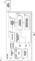
building 20 is illustrated inFigure 1 .Building 20 hasIT space 22. The IT space would be an area(s) housing servers and potentially other electronic equipment that will generate heat. Anair handling unit 24 delivers air into theIT space 22 to maintain a desired temperature level. - A
water chiller 26 is shown for supplying water to cool the air delivered from theair handling unit 24 into theIT space 22. Abuilding management system 28 controls the water chiller to achieve a desired air temperature and flow moving into theIT space 22. - As shown, an
ambient condition sensor 30 delivers a signal into thewater chiller 26, and into athermal optimization control 32.Thermal optimization control 32 includes a data centerinfo management system 34. The data centerinfo management system 34 receives a signal from theIT space 22, and from adata center operator 38.Data center operator 38 allows input of data center conditions from an operator to the data centerinfo management system 34. - As an example, the
data center operator 38 can send input signals of anticipated scheduling for operations that will be performed at various locations within theIT space 22. Thedata center operator 38 may also allow an individual to override a temperature optimized by thethermal optimization control 32. As an example, should an optimized temperature be lower or higher than the operator may desire, a signal may be sent to override the determined optimized temperature. -
Element 36 is an optimization engine and supervisory controls. - In the prior art, a temperature is selected for various locations within the building, and the water chiller is operated to achieve those present temperatures. The load on different locations in the
IT space 22 can change over time. As an example, there may be a server in one area of theIT space 22 that is performing a large amount of work at a particular time, while other servers are operating at a lower level. Thus, the heat loads at various spaces within theIT space 22 may vary. - It would be desirable to optimize the thermal management to achieve energy savings. To this end, data center HVAC setpoints can be varied versus remaining fixed per the above-mentioned design standard. Multiple thermal units can be managed cohesively in this manner so that they cooperate to achieve energy savings.
- In one main aspect of this disclosure, real-time and predicted IT load data may be utilized by the thermal
management optimization control 32 to optimize the thermal management and resulting energy use. - The disclosed system uses the real-time IT data to predict upcoming IT demand in a data center, and dynamically aligns thermal capacity with demand. In this manner, the disclosed system optimizes the chiller plant operating efficiency and provides supervisory control over data center operations.
- By addressing these issues, more efficient data center life cycle thermal management can be achieved. Organizations can achieve improved operation efficiency, reduced cost, enhance equipment reliability and increase sustainability in their data center operations.
-
Figure 2 is an overview of the operation under the disclosed method. As shown, thethermal optimization control 32 receives input shown at 40 from customer locations and associated weather data. Energy modeling is performed as shown schematically at 42. In addition, system dynamic modeling is performed as shown schematically atelement 44. IT load prediction is performed at 46, and optimization is performed at 48 based uponinputs thermal optimization control 32 from theIT space 22 itself. - The load prediction can be based upon historic data, the time of day, date, month or day of the week. Moreover, an operator may input upcoming IT events to assist with the prediction. As an example of historic data, it may be that a company performs a particular large IT intensive function on a particular day of the month. As one example, perhaps bills are mailed on the first Monday of a month. The historic data would store this, and utilize this to help anticipate a thermal load on the associated part of the
IT space 22. - The
energy modeling 42 captures power consumption modeling and energy consumption for the HVAC system, and in particular thewater chiller 26. The systemdynamic modeling 44 will capture system dynamics. - As examples of optimization, assuming the
building 20 is provided with three water chillers, the optimization may include a decision to operate all 3 on part load, or shutdown one and operate two on full load. Moreover, the volume of water passing from thechiller plant 26 to theair handling unit 24 may be varied to minimize energy consumption. -
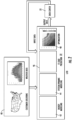
Figure 3 is an example diagram showing the overall control of this disclosure. As shown, thebuilding 20 may includerooftop HVAC systems 50, which may be water chillers. As can be seen, there may be a plurality of chillers, and illustrated here as 12. - There are also four
floors IT spaces 22. It should be appreciated that the load across the several floors will vary over time and relative to each other. As an example, perhaps theIT space 22 onfloor 56 will be performing a large task beginning an hour from now. That would be taken into account by thethermal optimization control 32, and factored into the optimization. - At 60, data and requirements are considered including a load profile of upcoming thermal loads, ambient weather, etc.
- Next at 62 an energy function and a load prediction are considered. This may include creating and computing piece-wise linear function at all valid points such as outside air temperature, water temperatures, the number of chillers being utilized, etc. Next, the optimization occurs at 64. Note, non-linear functions may be used.
- The objective for the optimization is to reduce energy consumptions with system constraints. The optimized actions include the number of chiller staging, leaving chilled water temperature (LWT), chilled water differential pressure, CRAH/C supply air temperature (SAT), or leaving air temperature.
- As shown at 62, an energy function utilizes a number of pieces of information as described above. A load prediction is also utilized and may be received from a data center infrastructure management system. The information could include historic load information and current load information. The historic load information could come with a timestamp from which the controller can determine time of day, day of the week, year and month.
-
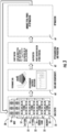
Figure 4 schematically shows options for step wise optimizing the thermal handling of a building. There are several possible steps along the way. - As an example, the staging or on/off state of the chillers may be the only step. As a second more extensive step the chiller staging may be optimized along with controlling a chiller water flow and temperature to achieve better savings. As yet another potential step, the entire data center can be managed cohesively as a system including controlling the volume of air and temperature of air, and controlling the HVAC system in this manner such that the several items cooperate to achieve the optimized operation, and not to compete. A volume of air delivered into the building may be controlled by controlling a fan for delivering the air into the building to reduce energy consumptions. Finally, and a further step, each of the above can be done along with rack level airflow management to components within servers or other electronic components in the IT space.
- For example, if the IT load predicts a certain row of racks will increase in the prediction horizon, we can increase the air flow in that row. Or if there is schedule maintenance shutdown of the servers in certain racks, one can reduce the air flow in that IT space.
- Notably, the term "CHW" refers to chiller water. The "T"s refer to temperature.
-
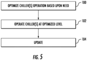
Figure 5 is a flow chart of the method according to this disclosure. Atstep 100, the HVAC system operation is optimized based upon current conditions in several locations within an IT space based upon current need and predicted need. Atstep 102 the chillers are operated at the optimized level. Atstep 104, the control continues to update the operation as conditions change. - A thermal optimization control under this disclosure could be said to include processing circuitry. The processing circuitry is operable to receive information from a building housing at least one computer server, with the information including at least a current thermal load. The processing circuitry is operable to control an associated HVAC system for at least an area of the building where the at least one computer server is housed. The processing circuity is operable to optimize the operation of the HVAC system based upon the current thermal load and an expected upcoming thermal load on the area of the building where the server is received to reduce energy usage by the HVAC system.
- The load information could be related to the thermal load and/or an associated power load for the IT system.
- A method of optimizing thermal conditioning under this disclosure could be said to include receiving information from a building housing at least one computer server, with the information including at least current thermal load. Thermal load information from the building is used to control an associated HVAC system for at least an area of the building where the at least one computer server is housed. Operation of the HVAC system is optimized based upon the current thermal load on the area of the building where the at least one computer server is housed to reduce energy usage by the HVAC system.
- The HVAC system is typically on the building roof. However, in some applications that benefit from this disclosure the HVAC system could be remote from the building.
- Although embodiments have been disclosed, a worker of skill in this art would recognize that modifications would come within the scope of this invention, which is as defined by the appended claims. For that reason, the following claims should be studied to determine the true scope of the invention.
Claims (15)
- A thermal optimization control (32) comprising:processing circuitry;the processing circuitry being operable to receive information from a building (20) housing at least one computer server, with the information including at least a current thermal load;the processing circuitry being operable to control an associated HVAC system for at least an area (22) of the building (20) where the at least one computer server is housed; andthe processing circuity being operable to optimize the operation of the HVAC system based upon the current thermal load and an expected upcoming thermal load on the area (22) of the building (20) where the server is received to reduce energy usage by the HVAC system.
- The control (32) as set forth in claim 1, wherein the optimization includes controlling a staging of a plurality of HVAC systems between on/off conditions and/or full load/partial load; and/or
wherein the optimization further includes controlling a volumetric flow and temperature of water delivered from one or more water chillers (26) to an air handling unit (24) to optimize and reduce energy consumption. - The control (32) as set forth in any preceding claim, wherein there are a plurality of the computer servers, and there are a plurality of areas (22) in the building (20) housing the plurality of computer servers.
- The control (32) as set forth in any preceding claim, wherein the thermal optimization control further has a memory being provided with historic thermal load information from the building (20).
- A method of optimizing thermal conditioning comprising:receiving information from a building (20) housing at least one computer server, with the information including at least current thermal load;using thermal load information from the building (20) to control an associated HVAC system for at least an area (22) of the building (20) where the at least one computer server is housed; andoptimizing (100) operation of the HVAC system based upon the current thermal load on the area (22) of the building (20) where the at least one computer server is housed to reduce energy usage by the HVAC system.
- The method as set forth in claim 5, wherein the HVAC system includes a plurality of water chillers (26) for cooling air to be delivered from an air handling unit (24) into the area (22) of the building (20) that houses the at least one computer server.
- The method as set forth in claim 6, wherein there are a plurality of the computer servers and a plurality of areas (22) in the building (20) receiving the plurality of computer servers.
- The method as set forth in claim 7, wherein the optimization includes controlling a staging of the plurality of water chillers (26) between on/off conditions and/or full load/partial load.
- The method as set forth in claim 8, wherein the optimization further includes controlling a volumetric flow and temperature of water delivered from the water chillers (26) to the air handling unit (24) to optimize and reduce energy consumption.
- The method as set forth in claim 9, wherein a volume of air delivered into the building (20) is controlled by controlling a fan for delivering air into the building (20) to reduce energy consumptions, optionally wherein air flow is managed at a rack level within the plurality of servers to reduce energy consumption.
- The method as set forth in any of claims 5 to 10, further including the step of using historic data in the optimization, optionally
wherein the historic data includes prior load information. - The method as set forth in claim 11, further including receiving information from an operator associated with the area (22) of the building (20) receiving the plurality of computer servers and controlling the HVAC system based upon the information received from the operator.
- A building (20) comprising:an area (22) housing at least one computer server;a HVAC system for the building (20); anda thermal optimization control (32) having processing circuitry, the processing circuitry being operable to receive information from the building (20), with the information including at least a current thermal load, the processing circuitry being operable to control the HVAC system for at least an area (22) of the building (20) where the at least one computer server is housed; andthe processing circuity being operable to optimize the operation of the HVAC system based upon the current thermal load on the area (22) of the building (20) where the server is received to reduce energy usage by the HVAC system.
- The building (20) as set forth in claim 13, wherein the HVAC system includes a plurality of water chillers (26) for cooling air to be delivered into the area (22) of the building (20) that houses the at least one computer server, and/or
wherein there are a plurality of the computer servers, and there are a plurality of areas (22) in the building (20) receiving the plurality of computer servers. - The building (20) as set forth in claim 13 or 14, wherein the thermal optimization control also has a memory with historic data on the thermal load, and/or
wherein the thermal optimization control (32) is configured to predict an upcoming thermal load in the optimization.
Applications Claiming Priority (1)
| Application Number | Priority Date | Filing Date | Title |
|---|---|---|---|
| US202363594457P | 2023-10-31 | 2023-10-31 |
Publications (1)
| Publication Number | Publication Date |
|---|---|
| EP4550958A1 true EP4550958A1 (en) | 2025-05-07 |
Family
ID=93335289
Family Applications (1)
| Application Number | Title | Priority Date | Filing Date |
|---|---|---|---|
| EP24209904.2A Pending EP4550958A1 (en) | 2023-10-31 | 2024-10-30 | Thermal optimization for data centers |
Country Status (3)
| Country | Link |
|---|---|
| US (1) | US20250138499A1 (en) |
| EP (1) | EP4550958A1 (en) |
| CN (1) | CN119922868A (en) |
Citations (4)
| Publication number | Priority date | Publication date | Assignee | Title |
|---|---|---|---|---|
| US20100076607A1 (en) * | 2008-08-08 | 2010-03-25 | Osman Ahmed | Data center thermal performance optimization using distributed cooling systems |
| US10247435B2 (en) * | 2016-06-29 | 2019-04-02 | International Business Machines Corporation | Real-time control of highly variable thermal loads |
| US20210262689A1 (en) * | 2018-06-15 | 2021-08-26 | Johnson Controls Technology Company | Cost savings from fault prediction and diagnosis |
| US11497144B2 (en) * | 2018-09-21 | 2022-11-08 | Johnson Controls Tyco IP Holdings LLP | Optimized thermal control of data center |
-
2024
- 2024-10-09 US US18/910,588 patent/US20250138499A1/en active Pending
- 2024-10-30 EP EP24209904.2A patent/EP4550958A1/en active Pending
- 2024-10-30 CN CN202411526620.9A patent/CN119922868A/en active Pending
Patent Citations (4)
| Publication number | Priority date | Publication date | Assignee | Title |
|---|---|---|---|---|
| US20100076607A1 (en) * | 2008-08-08 | 2010-03-25 | Osman Ahmed | Data center thermal performance optimization using distributed cooling systems |
| US10247435B2 (en) * | 2016-06-29 | 2019-04-02 | International Business Machines Corporation | Real-time control of highly variable thermal loads |
| US20210262689A1 (en) * | 2018-06-15 | 2021-08-26 | Johnson Controls Technology Company | Cost savings from fault prediction and diagnosis |
| US11497144B2 (en) * | 2018-09-21 | 2022-11-08 | Johnson Controls Tyco IP Holdings LLP | Optimized thermal control of data center |
Also Published As
| Publication number | Publication date |
|---|---|
| US20250138499A1 (en) | 2025-05-01 |
| CN119922868A (en) | 2025-05-02 |
Similar Documents
| Publication | Publication Date | Title |
|---|---|---|
| US8155793B2 (en) | System and method for controlling air conditioning facilities, and system and method for power management of computer room | |
| US12429241B2 (en) | Climate control adaptive temperature setpoint adjustment systems and methods | |
| US10605477B2 (en) | HVAC system with free cooling optimization based on coolant flowrate | |
| US8406929B2 (en) | Optimized control system for cooling systems | |
| EP2169328A2 (en) | Air-conditioning control system and air-conditioning control method | |
| US20100057259A1 (en) | System and method for dynamically managing blowers and vents | |
| US20100010678A1 (en) | System and method to control data center air handling systems | |
| US20130317654A1 (en) | Air-conditioning control system and air-conditioning control method | |
| US11892188B2 (en) | Capacity control for HVAC system | |
| Borkowski et al. | Customized data center cooling system operating at significant outdoor temperature fluctuations | |
| CN102105751A (en) | Group management device and group management system | |
| KR20240160164A (en) | Systems and methods for dynamic control of HVAC components in buildings | |
| JP2009014246A (en) | Electric / gas mixed air conditioning control system | |
| CN101216206A (en) | Air conditioner and its control method | |
| EP2653796A2 (en) | System and method for controlling air conditioner | |
| EP4550958A1 (en) | Thermal optimization for data centers | |
| US9869982B1 (en) | Data center scale utility pool and control platform | |
| US20090012651A1 (en) | Including Energy Price in Optimizing Refrigerant System Operation | |
| JP2009142113A (en) | Power control system, equipment controller, and equipment control program | |
| JP4920027B2 (en) | Linkage control method for air conditioning equipment and ICT equipment | |
| JP6955231B2 (en) | Maintenance support system | |
| JP5491987B2 (en) | Air conditioning controller | |
| JP4688112B2 (en) | Link control system and link control method for ICT equipment and facility | |
| US20150167994A1 (en) | Hvac control system | |
| JP7482464B1 (en) | Demand response power control system |
Legal Events
| Date | Code | Title | Description |
|---|---|---|---|
| PUAI | Public reference made under article 153(3) epc to a published international application that has entered the european phase |
Free format text: ORIGINAL CODE: 0009012 |
|
| STAA | Information on the status of an ep patent application or granted ep patent |
Free format text: STATUS: THE APPLICATION HAS BEEN PUBLISHED |
|
| AK | Designated contracting states |
Kind code of ref document: A1 Designated state(s): AL AT BE BG CH CY CZ DE DK EE ES FI FR GB GR HR HU IE IS IT LI LT LU LV MC ME MK MT NL NO PL PT RO RS SE SI SK SM TR |
|
| STAA | Information on the status of an ep patent application or granted ep patent |
Free format text: STATUS: REQUEST FOR EXAMINATION WAS MADE |
|
| 17P | Request for examination filed |
Effective date: 20251105 |