EP4438177A1 - Test arrangement for detecting a substance - Google Patents
Test arrangement for detecting a substance Download PDFInfo
- Publication number
- EP4438177A1 EP4438177A1 EP23165995.4A EP23165995A EP4438177A1 EP 4438177 A1 EP4438177 A1 EP 4438177A1 EP 23165995 A EP23165995 A EP 23165995A EP 4438177 A1 EP4438177 A1 EP 4438177A1
- Authority
- EP
- European Patent Office
- Prior art keywords
- test
- container
- plastic sleeve
- arrangement according
- test arrangement
- Prior art date
- Legal status (The legal status is an assumption and is not a legal conclusion. Google has not performed a legal analysis and makes no representation as to the accuracy of the status listed.)
- Pending
Links
- 238000012360 testing method Methods 0.000 title claims abstract description 314
- 239000000126 substance Substances 0.000 title claims abstract description 59
- 229920003023 plastic Polymers 0.000 claims abstract description 118
- 239000003708 ampul Substances 0.000 claims abstract description 83
- 239000007788 liquid Substances 0.000 claims abstract description 77
- 230000004913 activation Effects 0.000 claims abstract description 30
- 238000007654 immersion Methods 0.000 claims abstract 2
- 238000012546 transfer Methods 0.000 claims description 14
- 230000008859 change Effects 0.000 description 18
- 230000008878 coupling Effects 0.000 description 15
- 238000010168 coupling process Methods 0.000 description 15
- 238000005859 coupling reaction Methods 0.000 description 15
- 239000011521 glass Substances 0.000 description 15
- 239000000523 sample Substances 0.000 description 14
- 238000003825 pressing Methods 0.000 description 9
- 239000000463 material Substances 0.000 description 8
- 206010036790 Productive cough Diseases 0.000 description 7
- 210000003802 sputum Anatomy 0.000 description 7
- 208000024794 sputum Diseases 0.000 description 7
- 238000001514 detection method Methods 0.000 description 6
- 241000700605 Viruses Species 0.000 description 3
- 238000003780 insertion Methods 0.000 description 3
- 230000037431 insertion Effects 0.000 description 3
- 210000001519 tissue Anatomy 0.000 description 3
- 229920000742 Cotton Polymers 0.000 description 2
- 238000006243 chemical reaction Methods 0.000 description 2
- 238000005192 partition Methods 0.000 description 2
- 239000012620 biological material Substances 0.000 description 1
- 238000013461 design Methods 0.000 description 1
- 239000012530 fluid Substances 0.000 description 1
- 238000000034 method Methods 0.000 description 1
- 239000000203 mixture Substances 0.000 description 1
- 210000004400 mucous membrane Anatomy 0.000 description 1
- 210000002850 nasal mucosa Anatomy 0.000 description 1
- 230000002093 peripheral effect Effects 0.000 description 1
- 230000008569 process Effects 0.000 description 1
- 238000012545 processing Methods 0.000 description 1
- 238000003756 stirring Methods 0.000 description 1
- 230000007704 transition Effects 0.000 description 1
Images


Classifications
-
- B—PERFORMING OPERATIONS; TRANSPORTING
- B01—PHYSICAL OR CHEMICAL PROCESSES OR APPARATUS IN GENERAL
- B01L—CHEMICAL OR PHYSICAL LABORATORY APPARATUS FOR GENERAL USE
- B01L3/00—Containers or dishes for laboratory use, e.g. laboratory glassware; Droppers
- B01L3/50—Containers for the purpose of retaining a material to be analysed, e.g. test tubes
- B01L3/502—Containers for the purpose of retaining a material to be analysed, e.g. test tubes with fluid transport, e.g. in multi-compartment structures
- B01L3/5029—Containers for the purpose of retaining a material to be analysed, e.g. test tubes with fluid transport, e.g. in multi-compartment structures using swabs
-
- B—PERFORMING OPERATIONS; TRANSPORTING
- B65—CONVEYING; PACKING; STORING; HANDLING THIN OR FILAMENTARY MATERIAL
- B65D—CONTAINERS FOR STORAGE OR TRANSPORT OF ARTICLES OR MATERIALS, e.g. BAGS, BARRELS, BOTTLES, BOXES, CANS, CARTONS, CRATES, DRUMS, JARS, TANKS, HOPPERS, FORWARDING CONTAINERS; ACCESSORIES, CLOSURES, OR FITTINGS THEREFOR; PACKAGING ELEMENTS; PACKAGES
- B65D81/00—Containers, packaging elements, or packages, for contents presenting particular transport or storage problems, or adapted to be used for non-packaging purposes after removal of contents
- B65D81/32—Containers, packaging elements, or packages, for contents presenting particular transport or storage problems, or adapted to be used for non-packaging purposes after removal of contents for packaging two or more different materials which must be maintained separate prior to use in admixture
- B65D81/3216—Rigid containers disposed one within the other
- B65D81/3222—Rigid containers disposed one within the other with additional means facilitating admixture
-
- B—PERFORMING OPERATIONS; TRANSPORTING
- B01—PHYSICAL OR CHEMICAL PROCESSES OR APPARATUS IN GENERAL
- B01L—CHEMICAL OR PHYSICAL LABORATORY APPARATUS FOR GENERAL USE
- B01L2200/00—Solutions for specific problems relating to chemical or physical laboratory apparatus
- B01L2200/06—Fluid handling related problems
- B01L2200/0621—Control of the sequence of chambers filled or emptied
-
- B—PERFORMING OPERATIONS; TRANSPORTING
- B01—PHYSICAL OR CHEMICAL PROCESSES OR APPARATUS IN GENERAL
- B01L—CHEMICAL OR PHYSICAL LABORATORY APPARATUS FOR GENERAL USE
- B01L2200/00—Solutions for specific problems relating to chemical or physical laboratory apparatus
- B01L2200/16—Reagents, handling or storing thereof
-
- B—PERFORMING OPERATIONS; TRANSPORTING
- B01—PHYSICAL OR CHEMICAL PROCESSES OR APPARATUS IN GENERAL
- B01L—CHEMICAL OR PHYSICAL LABORATORY APPARATUS FOR GENERAL USE
- B01L2300/00—Additional constructional details
- B01L2300/04—Closures and closing means
- B01L2300/046—Function or devices integrated in the closure
- B01L2300/047—Additional chamber, reservoir
-
- B—PERFORMING OPERATIONS; TRANSPORTING
- B01—PHYSICAL OR CHEMICAL PROCESSES OR APPARATUS IN GENERAL
- B01L—CHEMICAL OR PHYSICAL LABORATORY APPARATUS FOR GENERAL USE
- B01L2300/00—Additional constructional details
- B01L2300/08—Geometry, shape and general structure
- B01L2300/0832—Geometry, shape and general structure cylindrical, tube shaped
-
- B—PERFORMING OPERATIONS; TRANSPORTING
- B01—PHYSICAL OR CHEMICAL PROCESSES OR APPARATUS IN GENERAL
- B01L—CHEMICAL OR PHYSICAL LABORATORY APPARATUS FOR GENERAL USE
- B01L2300/00—Additional constructional details
- B01L2300/08—Geometry, shape and general structure
- B01L2300/0861—Configuration of multiple channels and/or chambers in a single devices
- B01L2300/087—Multiple sequential chambers
-
- B—PERFORMING OPERATIONS; TRANSPORTING
- B01—PHYSICAL OR CHEMICAL PROCESSES OR APPARATUS IN GENERAL
- B01L—CHEMICAL OR PHYSICAL LABORATORY APPARATUS FOR GENERAL USE
- B01L2300/00—Additional constructional details
- B01L2300/12—Specific details about materials
- B01L2300/123—Flexible; Elastomeric
-
- B—PERFORMING OPERATIONS; TRANSPORTING
- B01—PHYSICAL OR CHEMICAL PROCESSES OR APPARATUS IN GENERAL
- B01L—CHEMICAL OR PHYSICAL LABORATORY APPARATUS FOR GENERAL USE
- B01L2400/00—Moving or stopping fluids
- B01L2400/04—Moving fluids with specific forces or mechanical means
- B01L2400/0475—Moving fluids with specific forces or mechanical means specific mechanical means and fluid pressure
- B01L2400/0481—Moving fluids with specific forces or mechanical means specific mechanical means and fluid pressure squeezing of channels or chambers
-
- B—PERFORMING OPERATIONS; TRANSPORTING
- B01—PHYSICAL OR CHEMICAL PROCESSES OR APPARATUS IN GENERAL
- B01L—CHEMICAL OR PHYSICAL LABORATORY APPARATUS FOR GENERAL USE
- B01L2400/00—Moving or stopping fluids
- B01L2400/06—Valves, specific forms thereof
- B01L2400/0677—Valves, specific forms thereof phase change valves; Meltable, freezing, dissolvable plugs; Destructible barriers
- B01L2400/0683—Valves, specific forms thereof phase change valves; Meltable, freezing, dissolvable plugs; Destructible barriers mechanically breaking a wall or membrane within a channel or chamber
Definitions
- the invention relates to a test arrangement for detecting a substance.
- Test arrangements for detecting a substance include, for example, a container in which a test liquid is kept.
- the arrangement is also equipped with a test swab, such as a cotton swab or the like, by means of which the substance can be obtained from a surface, for example from the mucous membrane of a person or from a laboratory table.
- the test swab is then dipped into the test liquid in the container and reacted with it.
- the substance can be detected using a measuring strip or by a color change of the test liquid mixed with the substance.
- Such a test arrangement can be used to detect certain chemical and/or biological substances or materials.
- the invention is based on the object of creating a test arrangement for the detection of a chemical and/or biological substance, which is characterized by a compact structure and which enables a reaction-stable storage of a test liquid.
- a test arrangement for detecting a chemical and/or biological substance comprising a plastic sleeve, an ampoule containing a test liquid and arranged in the plastic sleeve, a container with a mixing chamber for receiving and mixing the test liquid and the substance, and an activation device, by the actuation of which a The ampoule is broken open so that the test liquid is released into the mixing chamber, and a test swab is used to extract/collect the substance and immerse it in the mixing chamber.
- the test arrangement designed according to the invention enables the stable storage of a test liquid by means of the ampoule arranged in the plastic sleeve, which is made in particular from glass or a reaction-stable, defined breakable plastic.
- the mixing chamber which is formed by the container of the test arrangement, is in flow connection with a receiving chamber of the plastic sleeve, in which the ampoule is arranged, which can be broken open by actuating the activation device.
- the test liquid which is arranged in the ampoule in the delivery state, is handled in a sealed manner from the environment.
- the test liquid reacts with a substance that is introduced into the mixing chamber by means of the test collection stick.
- the substance is detected, for example, by a defined color change of the test liquid or by applying the test liquid that has reacted with the substance to a test strip, which experiences a color change when the substance is present.
- the test arrangement according to the invention is suitable for detecting any substances that can react with a test liquid, whereby the test liquid undergoes a color change as a result of the reaction and/or the test liquid containing the substance to be detected can additionally be applied to a test strip, which then undergoes coloration at least in a defined area when the substance to be detected is present.
- the container with the mixing chamber is preferably made of plastic or glass.
- the plastic sleeve and the container are formed from a one-piece component. It is particularly conceivable that the plastic sleeve and the container are arranged next to each other, one behind the other or one below the other.
- the container is detachably connected to the plastic sleeve and the mixing chamber of the Container is connected via a transfer opening, which is preferably formed on the plastic sleeve, to a receiving space of the plastic sleeve in which the ampoule is arranged.
- the plastic sleeve has a base or a partition wall, which in particular can also follow a conical surface or the like and which is provided with at least one transfer opening, which enables the test liquid to flow from the receiving space of the ampoule into the mixing space.
- the activation device of the test arrangement according to the invention by means of which the ampoule can be opened to release the test liquid, can be designed in a variety of ways.
- the activation device comprises a ramp-like projection which is formed on the inside of the plastic sleeve and which, when the activation device is actuated, interacts with the ampoule in such a way that a tip of the ampoule is broken off.
- the activation device can comprise an actuation button which can be pressed into the plastic sleeve and has, for example, on its inner side a particularly flat ramp which also interacts with a tip of the ampoule so that this tip can be broken off to open the ampoule.
- the activation device comprises defined pressure areas of the plastic sleeve.
- the pressure areas are in particular elastically deformable, so that a user of the test arrangement can break open the ampoule to release the test liquid by applying manual pressure.
- the ampoule In order to be able to break open the ampoule in a targeted manner, it is preferably designed as a glass or plastic ampoule, which is provided with two breakable, in particular needle-like tips in the broad sense.
- the tips can be broken off at defined predetermined breaking points from an ampoule body, which is in particular cylindrically shaped.
- a special embodiment of the test arrangement according to the invention has a pipetting bellows which is formed on the plastic sleeve.
- the container can have a base.
- the mixing chamber is arranged lower than the plastic sleeve or the ampoule arranged in the plastic sleeve.
- the container can have an introduction channel through which the substance to be detected can be introduced into the mixing chamber.
- the introduction channel can be arranged next to the plastic sleeve so that its axis is aligned parallel to the main axis of the plastic sleeve or the ampoule.
- the container of the test arrangement according to the invention is designed as a tube with one open end and one closed end, i.e. in the manner of a test tube.
- the container is preferably made of a transparent plastic or glass material, so that in particular a color change of the test liquid when it reacts with the sample material is visible from the outside.
- the container can have a discharge opening and/or a spout in a special embodiment of the test arrangement according to the invention.
- the outlet opening is preferably provided with a manual closure by means of which a controlled opening of the outlet opening is possible.
- the plastic sleeve and the container are arranged axially one behind the other, it is advantageous if the plastic sleeve has an apron that surrounds the container.
- the apron serves as a holder for the container on the plastic sleeve and also to seal the transition between the plastic sleeve and the container. It is of course also conceivable for the container to have an apron that surrounds the plastic sleeve in a corresponding manner.
- the container can have a stop on its circumference which interacts with the apron.
- the skirt together with an inner ring wall forms an annular groove into which an edge of the container is inserted.
- the container is designed, for example, in the manner of a test tube.
- the test collection stick is arranged or attached to the plastic sleeve so that it is immersed in the container.
- the plastic sleeve can be detached from the container together with the test collection stick and, for example, guided over a surface or biological tissue.
- the test collection stick is then pushed back into the container and the plastic sleeve is connected to the plastic sleeve in a fluid-tight manner.
- the test arrangement can then be activated by operating the activation device.
- the test liquid then flows into the mixing chamber in which the test collection stick is also arranged. If the substance to be detected has actually been absorbed by the test collection stick, the test liquid changes color due to the chemical reaction of the substance with the test liquid.
- the test collection stick is designed, for example, like a cotton swab or other sample collection stick.
- the latter can be provided with a ring wall which forms a receptacle for a shaft of the test stick.
- the activation device of the test arrangement according to the invention can further comprise an actuation button which can be pressed into the plastic sleeve and has on its inner side a particularly flat ramp which interacts with a tip of the ampoule so that when the activation device or the activation button is actuated, the ramp moves onto the tip and breaks it off.
- the container can be attached to a test plate which is provided with a test strip or the like.
- the test strip When the test strip is wetted with the test liquid and the substance to be detected is present, it undergoes a color change at least in some areas.
- a valve which controls a liquid flow between the mixing chamber of the container and a test chamber of the test plate, into which the test liquid is fed after mixing with the substance.
- the valve is in particular manually operable and preferably has a manually depressible actuation button for this purpose.
- the container can be pivotally attached to the test plate.
- a reservoir containing a reference liquid can be arranged on the test plate.
- the reference liquid can be released by operating a valve or the like.
- test arrangement 10 for detecting a chemical and/or biological substance or a chemical and/or biological material is shown.
- the test arrangement 10 comprises a plastic sleeve 12, a glass ampoule 14, which is designed as a so-called bitip ampoule and thus comprises a cylindrical ampoule body 15, which at each of its ends merges into a particularly needle-like tip 16 or 17, which can be broken off at a respective defined predetermined breaking point 18.
- the ampoule 14 made of glass contains a test liquid and is arranged in a receiving space 19 of the plastic sleeve 12.
- the plastic sleeve 12 is coupled at the front to a container 20, which is designed in the manner of a transparent test tube made of plastic or glass and delimits a mixing space 21.
- the plastic sleeve 12 has a coupling section 22 which is provided with an apron 23 which surrounds the container 20 in its end region bordering the plastic sleeve 12.
- the coupling section 22 has an annular wall 24 which, together with the apron 23, delimits an annular groove into which the edge of the container 20 bordering the plastic sleeve 12 is clamped.
- the test arrangement 10 further comprises a test or substance collection rod 25, which has a shaft 26 and a receiving area 27.
- the shaft 26 is received with its end area in a form-fitting manner by a shaft receptacle 28, which is formed on the coupling section 22 of the plastic sleeve 12.
- the test collection rod 25 is arranged eccentrically, i.e. offset in the radial direction.
- the coupling section 12 also forms a base 29 of the plastic sleeve 12, in which a transfer opening 30 is formed, which leads into a channel 31 running parallel to the shaft 26 of the test collection rod 25, which in turn opens into the mixing chamber 21 of the container 2.
- a connection is established between the receiving area 19 of the plastic sleeve 12 and the mixing chamber 21 of the container 20 made of plastic or glass via the transfer opening 30 and the channel 31.
- Press areas 32 and 33 of the plastic sleeve 12 represent an activation device by means of which the glass ampoule 14 can be opened or whose tips 16 and 17 can be broken off.
- test collection rod 25 attached to the plastic sleeve 12, so that material is collected which may contain the substance to be detected.
- the container 20 is then coupled to the plastic sleeve 12, i.e. at the coupling section 22 in the direction shown in Figure 4
- the tips 16, 17 are then broken off from the ampoule 14 by applying manual pressure to the pressure areas 32 and 33 of the plastic sleeve 12, so that a test liquid taken up by the ampoule 14 is released into the receiving space 19.
- the test liquid can now flow via the transfer opening 30 and the channel 31 into the mixing space 21 of the container 20, so that the receiving area 27 lies in the test liquid.
- test liquid into the mixing space 21 can be supported by means of a bellows-like end section 34 of the plastic sleeve 12.
- the test liquid reacts with the material arranged on the receiving area 27. If this contains the substance to be detected, the test liquid undergoes a defined color change. If no color change is carried out, the test is negative, which means that the chemical and/or biological substance in question cannot be detected.
- test arrangement 200 which essentially corresponds to that according to Figure 1 but differs from it in that the plastic sleeve 12 has a shaft receptacle 28 in its coupling section 22 facing the container 20, the axis of which coincides with the main axis of the test arrangement 10, so that the test collection rod 25 with its shaft 26 also lies in the central axis of the test arrangement 200.
- the plastic sleeve 12 of the test arrangement 200 comprises a base region 35, into which the tip 16 of the ampoule 15 engages and which is provided with several transfer openings 30, which are distributed along a circular line surrounding the tip 16 and which connect the receiving space 19 of the plastic sleeve 12 with the mixing space 21 of the container 20.
- the plastic sleeve 12 has, contrary to the embodiment according to the Figures 1 to 4 no bellows-like end section.
- test arrangement 200 corresponds to that according to the Figures 1 to 4 , which is why reference is made to the relevant description to avoid repetition.
- the application of test arrangement 200 also corresponds to the application of the test arrangement according to the Figures 1 to 4 .
- a test arrangement 300 which also comprises a plastic sleeve 12 with a coupling section 22, an ampoule 14 made of glass with two breakable tips 16 and 17 and an ampoule body 15 connecting the two tips 16 and 17 to one another, as well as a test tube-like container 20 and a test collection rod 25 with a shaft 26 and a receiving area 27.
- a coupling section 22 also comprises an apron 23 and an annular wall 24, between which an edge section of the container 20 is clamped.
- the container 20 has an annular collar 36, which specifies the insertion depth of the container 20 into the coupling section 22 of the plastic sleeve 12.
- the shaft 26 of the test collection stick 25 is inserted into a tube-like shaft receptacle 28, which is also formed on the coupling section 22 of the plastic sleeve 12.
- an inner wall 37 is formed on the plastic sleeve 12, which follows a conical surface and on which a plurality of window-like transfer openings 30 are formed all around, which establish a connection between a receiving space 19 of the plastic sleeve 12 and a mixing space 21 of the container 20.
- the test arrangement 300 is further provided with an activation device 38, which on the one hand comprises an actuation button 39 which is slidably mounted in the plastic sleeve 12 and has a particularly flat ramp 40 on the inside which serves to break off the tip 17 of the ampoule 14.
- the activation device 38 comprises a ramp 42 formed on a projection 41 which serves to break off the tip 16 of the ampoule 14.
- test collection rod 25 attached to the plastic sleeve 12 is first moved with its receiving area 27 over a surface to be examined in order to collect material.
- the container 20 is then placed in the Figure 11
- the test strip 25 is then pulled over the test strip 25 in the manner shown and fixed to the coupling section 22.
- the activation device 38 is then actuated, i.e. the actuation button 39 is pressed axially into the plastic sleeve 12 so that the tip 16 moves up onto the ramp 42 and is broken off and the ramp 40 moves up onto the tip 17 and breaks it off.
- test liquid held in the ampoule 14 can flow from the receiving space 19 via the transfer openings 30 into the mixing space 21 of the container 20.
- the receiving area 27 of the test collection strip 25 is exposed to the test liquid.
- the test liquid can react with a material arranged on the receiving area 27. If the substance to be detected is contained, the test liquid undergoes a color change which can be visually detected by the user. Without a color change, the test is negative, which means that the substance in question cannot be detected.
- test arrangement 400 which is also suitable for detecting a chemical and/or biological substance.
- the test arrangement 400 comprises a housing 42 which has a plastic sleeve 12 with a receiving space 19 for receiving a glass ampoule 14 which comprises an ampoule body 15 and two tips 16 and 17 which can each be broken off from the ampoule body 15 via a defined predetermined breaking point 18.
- the housing 42 comprises an insert 43, which represents a container 20 in which a mixing chamber 21 is formed.
- the insert 43 can be displaced relative to a housing section 44 of the housing 42 forming the plastic sleeve 12.
- the insert 43 can be pressed into the housing section 44 in order to activate the test arrangement 400.
- the insert 43 has a ramp 42 which interacts with the tip 16 of the ampoule.
- the insert 43, which forms the container 20, is therefore also part of the activation device.
- the housing section 44 which receives the ampoule 14 in the receiving space 19, forms a channel 45 parallel to the receiving space 19, via which, on the one hand, a test collection rod 25, on which a receiving area 27 is formed, can be introduced into the mixing space 21 and, on the other hand, a test liquid contained in the mixing space 21 can be applied to a test cassette 46, which is provided with an indicator strip, by means of a dosing cap 46, which can be inserted into a front end of the channel 45.
- the test arrangement 400 is used in such a way that a sample is first obtained using the test collection rod 25.
- the housing 420 is then activated by pressing the insert 43 into the housing section 44.
- the tips 15 and 17 of the ampoule 14 are broken off by means of the ramps 40 and 42 and the test liquid held in the ampoule 14 is released into the mixing chamber 21.
- the test collection rod 25 is introduced into the mixing chamber 21 via the channel 45. Mixing chamber 20 so that the material arranged on the receiving area 27 can react with the test liquid (cf. Figure 16 ).
- the test collection rod 25 is then removed from the housing 420 so that the dosing cap 46 can be fitted (cf. Figure 17 ) and the test liquid can be applied to the test cassette 47 via the dosing cap 46. If the test strip of the test cassette 47 then changes color at least in some areas, a certain substance has been detected. Without a color change, the substance in question is not detected.
- a test arrangement 500 which has a plastic tube 510 which forms a plastic sleeve 12 in which a receiving space 19 for an ampoule 14 of the type described in connection with the prescribed embodiments is formed.
- the plastic tube 510 comprises a pipetting section 50 which is provided with a bellows region 51 and a pipetting tip 52.
- the test arrangement 500 comprises a container 20 which is designed in the manner of a small trough and has a mixing chamber 21.
- the test arrangement 500 comprises a test collection rod 25 with a receiving area 27.
- test cassette 47 with a test or indicator strip is provided.
- the plastic tube 510 comprises defined pressing areas 32 and 33 as an activation device for breaking off the tips 16 and 17 of the ampoule 15, via which a user can break off the tips 16 and 17 to release the test liquid held in the ampoule 14.
- test arrangement 500 When using the test arrangement 500, a surface or tissue is first wiped over using the test collection stick 25 in order to collect a sample or material.
- the ampoule 14 is then broken open via the pressing areas 32 and 33 so that the test liquid flows into an interior 53 of the pipetting section 50 of the plastic tube 10.
- the test liquid is then manually Pressing the bellows area 51 over the pipette tip 52 into the mixing chamber 21 of the container 22.
- the test collection stick 25 is then dipped with its receiving area 27 into the test liquid in the mixing chamber 21. After a defined dwell time, the test collection stick 25 is removed again and the test liquid mixed with the sample is drawn into the pipette section 50 of the plastic tube 510. This can then be added drop by drop to the test cassette 47. If there is then a color change at least in some areas on the test strip of the test cassette, a certain substance contained in the sample has been detected. Without a color change, there is no detection.
- a test arrangement 600 is shown which essentially corresponds to that according to the Figures 19 and 20 corresponds, but differs from this only in that it has an actuating button 39 as an activation device on the plastic tube 510, which is provided with a ramp 40 that interacts with the tip 17 of the ampoule 14, wherein the actuating button 39 can be pressed into the receiving area for the ampoule 14, which forms a plastic sleeve 12.
- a further ramp 42 is formed in the receiving space 19 of the plastic sleeve 12, onto which the tip 16 moves when the actuating button 39 is pressed. The tips 16 and 17 are thus broken off from the ampoule body 15 by pressing the actuating button 39 by means of the ramps 40 and 42.
- test arrangement 600 corresponds to that of the test arrangement according to the Figures 19 and 20 , which is why, to avoid repetition, reference is made to the relevant description.
- test arrangement 700 which has a carrier plate designed as a test cassette 47, on which a container 20 is arranged, which encloses a mixing chamber 21.
- the container 20 has an annular wall 60.
- a plastic sleeve 12 is inserted into the ring wall 60 of the test arrangement 700, which is provided with a coupling section 22 which has a ring wall 61 whose outer diameter corresponds to the inner diameter of the ring wall 60 of the container 20.
- the plastic sleeve 12 forms a receiving space 19 for an ampoule 14, which also has two tips 16 and 17, which delimit a cylindrical ampoule body 15 at the end.
- the test arrangement 700 comprises an actuation button 39 which can be pressed into the receiving space 19 of the plastic sleeve 12 and has a ramp 40 on the inside which interacts with the tip 17 of the ampoule 14.
- the plastic sleeve 12 On the side facing away from the actuation button 39, the plastic sleeve 12 has a further ramp 42 in the region of the coupling section 22 which interacts with the other tip 16 of the ampoule 14.
- a transfer channel 62 which can be optionally opened or closed by means of a manually operable slide valve 63.
- a container 64 for reference liquid is arranged on the test cassette 47. By applying axial vertical pressure to the container 64, the reference liquid contained therein can be released in the direction of the test strip of the test cassette 47.
- the plastic sleeve 12 When using the test arrangement 700 to detect a chemical and/or biological substance, the plastic sleeve 12 is first removed from the container 20. The user can then introduce his sputum or another sample from above into the mixing chamber 21 of the container 20. The plastic sleeve 12 is then placed back on the container 20. The user then presses the actuation button 39 in an axial direction so that the tips 16 and 17 of the ampoule 14 are broken off and the test liquid contained therein flows downwards into the mixing chamber 21 and mixes with the sputum.
- the slide valve 63 is actuated so that the fluid flow between the mixing chamber 21 and the test cassette 47 is released and it can be determined by means of the test strip of the test cassette 47 whether a certain substance, for example a virus, is present in the sputum.
- the detection is carried out by the test strip undergoing a color change. If necessary, the test result can be checked using the reference liquid by pressing the container 64.
- a test arrangement 800 which comprises a plastic sleeve 12 with a receiving space for receiving an ampoule 14 and a container 20 in which a mixing space 21 is formed.
- the container 20 also has a discharge opening 65 which is closed by means of a cap.
- the discharge opening 65 can also be closed by means of a one-piece molded and twist-off closure.
- the test arrangement 800 has a test cassette 47 with test strips.
- the plastic sleeve 12 has two defined pressing areas 32 and 33. By exerting manual pressure on the pressing areas 32 and 33, tips 16 and 17 of the ampoule 14 can be broken off at defined predetermined breaking points so that a test liquid held in the ampoule is released.
- the user When using the test arrangement 800, the user first removes the plastic sleeve 12 from the container 20 so that he can introduce sputum or another sample into the mixing chamber 21 of the container 20. He then inserts the plastic sleeve 12 back into the container 20 so that an annular wall 61 of the plastic sleeve 12 rests against a corresponding annular wall of the container 20 from the inside. The insertion depth is determined by an annular collar 67 which is formed on the plastic sleeve 12.
- the user then presses on the pressing areas 32 and 33, which represent an activation device, so that the tips 16 and 17 of the ampoule 14 are broken off and the test liquid flows from the ampoule 14 into the mixing chamber 21 and mixes there with the sputum.
- the mixing process can be assisted by shaking the arrangement if necessary.
- the cap 66 is then removed and the mixture of the test liquid and the sputum is dosed onto the test cassette 47. If a certain substance, for example a virus, is present in the sputum, the test strip of the test cassette 47 undergoes a color change at least in some areas. This makes it possible to detect this substance, i.e. the virus.
- test arrangement 900 is shown, which largely corresponds to that according to the Figures 30 to 32 but differs from it in that it additionally has a test collection stick 25 which has a receiving area 27 and a shaft 26.
- test arrangement 900 corresponds to that according to the Figures 30 to 32 .
- test swab 25 for example from the nasal mucosa of a user.
- the test swab 25 is then placed in the Figure 35 introduced into the container 20 in the manner shown, so that the receiving area 27 of the test collection stick 25 is in the mixing chamber 21.
- the ampoule 14 is opened by breaking off the tips 16 and 17, the receiving area 27 of the test collection stick 25 is flushed with the test liquid, so that the sample arranged on the receiving area 27 can react with the test liquid.
- the test liquid is applied to the test cassette 47, so that a substance contained in the sample can be detected by means of the test strip of the test cassette 47.
- a test arrangement 1000 is shown, which essentially corresponds to that according to the Figures 33 to 35 corresponds, but differs from this in that the plastic sleeve 12 has an actuating button 39 with an internal ramp 40 as an activation device, which interacts with a ramp 42 formed in one piece on the inside of the plastic sleeve 12 in such a way that when the actuating button 39 is moved into the plastic sleeve 12, the tip 17 is broken off by means of the ramp 40 and the tip 16 of the ampoule 14 is broken off by means of the ramp 42, so that the test liquid held in the ampoule 14 can flow into the mixing chamber 21 of the container 20, so that the receiving area 27 of the test collection stick 25 is washed by the test liquid.
- arrangement 1000 corresponds to the structure and application of the test arrangement according to the Figures 33 to 35 , so that in order to avoid repetition, reference is made to the relevant description.
- a test arrangement 1100 which has a plastic sleeve 12 which accommodates a receiving space 19 for a glass ampoule 14 of the type mentioned in the examples described above.
- the plastic sleeve 12 is arranged on a trough-like container 20 with which it is manufactured in one piece.
- the container 20 has a mixing chamber 21 which is provided with a spout 70 and is open at the top.
- the plastic sleeve 12 On the side facing away from the container 20, the plastic sleeve 12 has an actuating button 39 as an activation device, which is provided on the inside with a ramp 40 which interacts with a tip 17 of the ampoule 14. On the side facing away from the actuating button 39, the plastic sleeve 12 has a ramp 42 which is formed by a base surface.
- test arrangement 1100 is provided with a test collection stick 25, which also has a receiving area 27.
- test collection stick 25 During use, a sample is taken from a surface or tissue using the test collection stick 25.
- the actuating button 39 is then pressed downwards so that the tips 16 and 17 of the ampoule 14 break off by means of the ramps 40 and 42 and the test liquid contained in the ampoule 14 flows through a transfer opening 30 from the plastic sleeve 12 into the mixing chamber 21 of the container 20.
- the test collection stick 25 is then immersed with its receiving area 27 into the test liquid in the mixing chamber 21, if necessary while stirring.
- test liquid can then be dosed via the spout 70 onto a test cassette 47 with test strips, so that the detection of a substance collected using the test collection stick 25 is possible. If the test strip changes color, the substance has been detected. Without a color change, detection cannot be carried out.
- a test arrangement 1200 which has a receiving housing 420 with a base 71 which is formed by a conical wall which is formed on a container 20 which forms a mixing chamber 21.
- a plastic sleeve 12 is formed in one piece on the container 20 and has a receiving chamber 19 for a glass ampoule 14 which is formed in accordance with the glass ampoule of the embodiments described above.
- test arrangement 1200 has an insert 72 at the top, which is provided on the one hand with an activation device in the form of a ramp 40 and on the other hand with a drain 70.
- the ramp 40 is formed by an internal, inclined partition wall.
- the container 20 On the side facing away from the insert 72 which can be axially displaced in the plastic sleeve 12, the container 20 has a further ramp 42 through an inclined boundary wall of the mixing chamber 21, which cooperates with the tip 16 of the ampoule 14.
- the diameter of the plastic sleeve 12 is selected such that a test collection rod 25 with its receiving area 27 can be introduced past the ampoule into the mixing chamber 21 via the tube-like insert 72, the outer diameter of the ampoule 15 is therefore smaller than the inner diameter of the plastic sleeve 12.
- a sample is first obtained using the test collection stick 25.
- the test collection stick 25 is then introduced into the mixing chamber 21 with its receiving area 27 via the insert 72 and the free space between the ampoule 14 and the peripheral wall of the plastic sleeve 12 in the manner described above.
- the insert 72 is then pressed into the plastic sleeve 12 so that the tips 16 and 17 of the ampoule 14 are broken off by means of the ramps 40 and 42 and the test liquid held in the ampoule 14 flows into the mixing chamber 21.
- the test collection stick 25 can then be removed and the test liquid can be dosed onto a test cassette 47 via the spout 70. If the substance to be detected is present in the sample, the test strip of the test cassette 47 undergoes a color change. Otherwise there will be no color change.
Landscapes
- Health & Medical Sciences (AREA)
- Chemical & Material Sciences (AREA)
- Engineering & Computer Science (AREA)
- Mechanical Engineering (AREA)
- Analytical Chemistry (AREA)
- General Health & Medical Sciences (AREA)
- Hematology (AREA)
- Clinical Laboratory Science (AREA)
- Chemical Kinetics & Catalysis (AREA)
- Investigating Or Analysing Biological Materials (AREA)
Abstract
Es wird eine Testanordnung zum Nachweis einer Substanz vorgeschlagen, umfassend eine Kunststoffhülse (12), eine Ampulle (15), die eine Testflüssigkeit aufnimmt und die in der Kunststoffhülse (12) angeordnet ist, einen Behälter (20) mit einem Mischraum (21) zur Aufnahme und zum Mischen der Testflüssigkeit und der Substanz, sowie eine Aktivierungseinrichtung, durch deren Betätigung ein Aufbrechen der Ampulle (15) erfolgt, so dass die Testflüssigkeit in den Mischraum (21) freigegeben wird, und ein Testsammelstäbchen (25) zum Eintauchen in den Mischraum (21).

Description
Die Erfindung betrifft eine Testanordnung zum Nachweis einer Substanz.The invention relates to a test arrangement for detecting a substance.
Testanordnungen zum Nachweis einer Substanz sind aus der Praxis bekannt und umfassen beispielsweise einen Behälter, in dem eine Testflüssigkeit vorgehalten ist. Zudem ist die Anordnung mit einem Testsammelstäbchen, wie Wattestäbchen oder dergleichen, ausgestattet, mittels dessen die Substanz von einer Oberfläche, beispielsweise von der Schleimhaut eines Menschen oder von einem Labortisch, gewonnen werden kann. Das Testsammelstäbchen wird dann in den Behälter in die Testflüssigkeit getaucht und mit dieser zur Reaktion gebracht. Über einen Messstreifen oder auch durch einen Farbumschlag der mit der Substanz vermischten Testflüssigkeit kann die Substanz nachgewiesen werden. Eine solche Testanordnung kann zum Nachweis bestimmter chemischer und/oder biologischer Substanzen bzw. Stoffe eingesetzt werden.Test arrangements for detecting a substance are known in practice and include, for example, a container in which a test liquid is kept. The arrangement is also equipped with a test swab, such as a cotton swab or the like, by means of which the substance can be obtained from a surface, for example from the mucous membrane of a person or from a laboratory table. The test swab is then dipped into the test liquid in the container and reacted with it. The substance can be detected using a measuring strip or by a color change of the test liquid mixed with the substance. Such a test arrangement can be used to detect certain chemical and/or biological substances or materials.
Der Erfindung liegt die Aufgabe zugrunde, eine Testanordnung zum Nachweis einer chemischen und/oder biologischen Substanz zu schaffen, welche sich durch einen kompakten Aufbau auszeichnet und die eine reaktionsstabile Lagerung einer Testflüssigkeit ermöglicht.The invention is based on the object of creating a test arrangement for the detection of a chemical and/or biological substance, which is characterized by a compact structure and which enables a reaction-stable storage of a test liquid.
Diese Aufgabe ist erfindungsgemäß durch die Testanordnung mit den Merkmalen des Anspruchs 1 gelöst.This object is achieved according to the invention by the test arrangement having the features of
Erfindungsgemäß wird also eine Testanordnung zum Nachweis einer chemischen und/oder biologischen Substanz vorgeschlagen, umfassend eine Kunststoffhülse, eine Ampulle, die eine Testflüssigkeit enthält und die in der Kunststoffhülse angeordnet ist, einen Behälter mit einem Mischraum zur Aufnahme und zum Mischen der Testflüssigkeit und der Substanz sowie eine Aktivierungseinrichtung, durch deren Betätigung ein Aufbrechen der Ampulle erfolgt, so dass die Testflüssigkeit in den Mischraum freigegeben wird, und ein Testsammelstäbchen (Swab) zum Gewinnen/Sammeln der Substanz und zum Eintauchen in den Mischraum.According to the invention, a test arrangement for detecting a chemical and/or biological substance is proposed, comprising a plastic sleeve, an ampoule containing a test liquid and arranged in the plastic sleeve, a container with a mixing chamber for receiving and mixing the test liquid and the substance, and an activation device, by the actuation of which a The ampoule is broken open so that the test liquid is released into the mixing chamber, and a test swab is used to extract/collect the substance and immerse it in the mixing chamber.
Die erfindungsgemäß ausgebildete Testanordnung ermöglicht durch die in der Kunststoffhülse angeordnete Ampulle, die insbesondere aus Glas oder einem reaktionsstabilen, definiert brechbaren Kunststoff gefertigt ist, die stabile Lagerung einer Testflüssigkeit. Der Mischraum, der von dem Behälter der Testanordnung gebildet ist, steht in Fließverbindung mit einem Aufnahmeraum der Kunststoffhülse, in dem die Ampulle angeordnet ist, die durch Betätigung der Aktivierungseinrichtung aufgebrochen werden kann. Idealerweise erfolgt damit das Handling der Testflüssigkeit, die im Lieferzustand in der Ampulle angeordnet ist, abgedichtet gegenüber der Umgebung. In dem Mischraum reagiert die Testflüssigkeit mit Substanz, die mittels des Testsammelstäbchens in den Mischraum eingebracht wird. Ein Nachweis der Substanz erfolgt beispielsweise über einen definierten Farbumschlag der Testflüssigkeit oder auch durch Aufbringen der mit der Substanz reagierten Testflüssigkeit auf einen Teststreifen, der bei Vorliegen der Substanz einen Farbumschlag erfährt.The test arrangement designed according to the invention enables the stable storage of a test liquid by means of the ampoule arranged in the plastic sleeve, which is made in particular from glass or a reaction-stable, defined breakable plastic. The mixing chamber, which is formed by the container of the test arrangement, is in flow connection with a receiving chamber of the plastic sleeve, in which the ampoule is arranged, which can be broken open by actuating the activation device. Ideally, the test liquid, which is arranged in the ampoule in the delivery state, is handled in a sealed manner from the environment. In the mixing chamber, the test liquid reacts with a substance that is introduced into the mixing chamber by means of the test collection stick. The substance is detected, for example, by a defined color change of the test liquid or by applying the test liquid that has reacted with the substance to a test strip, which experiences a color change when the substance is present.
Grundsätzlich eignet sich die Testanordnung nach der Erfindung zum Nachweis jeglicher Substanzen, die mit einer Testflüssigkeit reagieren können, wobei die Testflüssigkeit durch die Reaktion einem Farbumschlag unterliegt und/oder die mit der nachzuweisenden Substanz beaufschlagte Testflüssigkeit zusätzlich auf einen Teststreifen aufgebracht werden kann, der dann bei Vorliegen der nachzuweisenden Substanz zumindest in einem definierten Bereich eine Einfärbung erfährt.In principle, the test arrangement according to the invention is suitable for detecting any substances that can react with a test liquid, whereby the test liquid undergoes a color change as a result of the reaction and/or the test liquid containing the substance to be detected can additionally be applied to a test strip, which then undergoes coloration at least in a defined area when the substance to be detected is present.
Der Behälter mit dem Mischraum ist vorzugsweise aus Kunststoff oder Glas gefertigt.The container with the mixing chamber is preferably made of plastic or glass.
Bei einer speziellen Ausführungsform der Testanordnung nach der Erfindung sind die Kunststoffhülse und der Behälter von einem einstückigen Bauteil gebildet. Denkbar ist es insbesondere, dass die Kunststoffhülse und der Behälter nebeneinander, hintereinander bzw. untereinander angeordnet sind.In a special embodiment of the test arrangement according to the invention, the plastic sleeve and the container are formed from a one-piece component. It is particularly conceivable that the plastic sleeve and the container are arranged next to each other, one behind the other or one below the other.
Bei einer weiteren speziellen Ausführungsform der Testanordnung nach der Erfindung ist der Behälter lösbar mit der Kunststoffhülse verbunden und der Mischraum des Behälters über eine Transferöffnung, die vorzugsweise an der Kunststoffhülse ausgebildet ist, mit einem Aufnahmeraum der Kunststoffhülse verbunden, in dem die Ampulle angeordnet ist. Beispielsweise weist die Kunststoffhülse einen Boden bzw. eine Trennwand auf, die insbesondere auch einer Kegelfläche oder dergleichen folgen kann und die mit mindestens einer Transferöffnung versehen ist, welche ermöglichst, dass die Testflüssigkeit aus dem Aufnahmeraum der Ampulle in den Mischraum fließt.In a further special embodiment of the test arrangement according to the invention, the container is detachably connected to the plastic sleeve and the mixing chamber of the Container is connected via a transfer opening, which is preferably formed on the plastic sleeve, to a receiving space of the plastic sleeve in which the ampoule is arranged. For example, the plastic sleeve has a base or a partition wall, which in particular can also follow a conical surface or the like and which is provided with at least one transfer opening, which enables the test liquid to flow from the receiving space of the ampoule into the mixing space.
Die Aktivierungseinrichtung der Testanordnung nach der Erfindung, mittels der die Ampulle zur Freigabe der Testflüssigkeit öffenbar ist, kann in vielfältiger Weise ausgebildet sein. Beispielsweise umfasst die Aktivierungseinrichtung einen rampenartigen Vorsprung, welcher innenseitig an der Kunststoffhülse ausgeformt ist und der bei einer Betätigung der Aktivierungseinrichtung so mit der Ampulle zusammenwirkt, dass eine Spitze derselben abgebrochen wird.The activation device of the test arrangement according to the invention, by means of which the ampoule can be opened to release the test liquid, can be designed in a variety of ways. For example, the activation device comprises a ramp-like projection which is formed on the inside of the plastic sleeve and which, when the activation device is actuated, interacts with the ampoule in such a way that a tip of the ampoule is broken off.
Des Weiteren kann die Aktivierungseinrichtung einen Betätigungsknopf umfassen, der in die Kunststoffhülse eindrückbar ist und beispielsweise an seiner Innenseite eine insbesondere ebene Rampe aufweist, die ebenfalls mit einer Spitze der Ampulle zusammenwirkt, so dass diese Spitze zum Öffnen der Ampulle abbrechbar ist.Furthermore, the activation device can comprise an actuation button which can be pressed into the plastic sleeve and has, for example, on its inner side a particularly flat ramp which also interacts with a tip of the ampoule so that this tip can be broken off to open the ampoule.
Zudem ist es denkbar, dass die Aktivierungseinrichtung definierte Drückbereiche der Kunststoffhülse umfasst. Die Drückbereiche sind insbesondere elastisch verformbar, so dass ein Nutzer der Testanordnung durch Aufbringen eines manuellen Drucks die Ampulle zur Freigabe der Testflüssigkeit aufbrechen kann.It is also conceivable that the activation device comprises defined pressure areas of the plastic sleeve. The pressure areas are in particular elastically deformable, so that a user of the test arrangement can break open the ampoule to release the test liquid by applying manual pressure.
Um die Ampulle gezielt aufbrechen zu können, ist diese vorzugsweise als Glas- oder Kunststoffampulle ausgebildet, die mit zwei abbrechbaren, insbesondere im weiten Sinne nadelartigen Spitzen versehen ist. Die Spitzen sind an definierten Sollbruchstellen von einem Ampullenkörper abbrechbar, welcher insbesondere zylindrisch ausgeformt ist.In order to be able to break open the ampoule in a targeted manner, it is preferably designed as a glass or plastic ampoule, which is provided with two breakable, in particular needle-like tips in the broad sense. The tips can be broken off at defined predetermined breaking points from an ampoule body, which is in particular cylindrically shaped.
Um die Testflüssigkeit möglichst effektiv aus dem Aufnahmeraum der Ampulle in den Mischraum des Behälters fördern zu können, weist eine spezielle Ausführungsform der Testanordnung nach der Erfindung einen Pipettierbalg auf, der an der Kunststoffhülse ausgebildet ist.In order to be able to convey the test liquid as effectively as possible from the receiving space of the ampoule into the mixing space of the container, a special embodiment of the test arrangement according to the invention has a pipetting bellows which is formed on the plastic sleeve.
Um die Handhabung der Testanordnung nach der Erfindung insbesondere bei der Ausführungsform, bei der die Kunststoffhülse und der Behälter von einem einstückigen Bauteil gebildet sind, zu verbessern, kann der Behälter eine Standfläche aufweisen. In diesem Falle ist es vorteilhaft, wenn der Mischraum tiefer angeordnet ist als die Kunststoffhülse bzw. die in der Kunststoffhülse angeordnete Ampulle. Zudem kann der Behälter einen Einführkanal aufweisen, über den die nachzuweisende Substanz in den Mischraum eingebracht werden kann. Der Einführkanal kann neben der Kunststoffhülse angeordnet sein, so dass dessen Achse parallel zur Hauptachse der Kunststoffhülse bzw. der Ampulle ausgerichtet ist.In order to improve the handling of the test arrangement according to the invention, particularly in the embodiment in which the plastic sleeve and the container are formed from a one-piece component, the container can have a base. In this case, it is advantageous if the mixing chamber is arranged lower than the plastic sleeve or the ampoule arranged in the plastic sleeve. In addition, the container can have an introduction channel through which the substance to be detected can be introduced into the mixing chamber. The introduction channel can be arranged next to the plastic sleeve so that its axis is aligned parallel to the main axis of the plastic sleeve or the ampoule.
Der Behälter der Testanordnung nach der Erfindung ist bei einer vorteilhaften Ausführungsform als Röhrchen mit einem offenen Ende und einem geschlossenen Ende, d.h. nach Art eines Reagenzglases ausgebildet. In diesem Falle ist der Behälter vorzugsweise aus einem transparenten Kunststoff- oder Glaswerkstoff gefertigt, so dass insbesondere ein Farbumschlag der Testflüssigkeit bei deren Reaktion mit dem Probenmaterial von außen sichtbar ist.In an advantageous embodiment, the container of the test arrangement according to the invention is designed as a tube with one open end and one closed end, i.e. in the manner of a test tube. In this case, the container is preferably made of a transparent plastic or glass material, so that in particular a color change of the test liquid when it reacts with the sample material is visible from the outside.
Um die Testflüssigkeit, die in dem Mischraum mit der Substanz versetzt wurde, zur Weiterverarbeitung aus dem Behälter ausbringen zu können, kann der Behälter bei einer speziellen Ausführungsform der Testanordnung nach der Erfindung eine Austragöffnung und/oder einen Ausguss aufweisen.In order to be able to discharge the test liquid, which has been mixed with the substance in the mixing chamber, from the container for further processing, the container can have a discharge opening and/or a spout in a special embodiment of the test arrangement according to the invention.
Die Auslauföffnung ist vorzugsweise mit einem manuellen Verschluss versehen, mittels dessen ein kontrolliertes Öffnen der Auslauföffnung möglich ist.The outlet opening is preferably provided with a manual closure by means of which a controlled opening of the outlet opening is possible.
Bei einer Ausführungsform, bei der die Kunststoffhülse und der Behälter axial hintereinander angeordnet sind, ist es vorteilhaft, wenn die Kunststoffhülse eine Schürze aufweist, die den Behälter umgreift. Die Schürze dient als Halterung für den Behälter an der Kunststoffhülse und auch zur Dichtung des Übergangs zwischen der Kunststoffhülse und dem Behälter. Denkbar ist es natürlich auch, dass der Behälter eine Schürze aufweist, welche die Kunststoffhülse in entsprechender Weise umgreift.In an embodiment in which the plastic sleeve and the container are arranged axially one behind the other, it is advantageous if the plastic sleeve has an apron that surrounds the container. The apron serves as a holder for the container on the plastic sleeve and also to seal the transition between the plastic sleeve and the container. It is of course also conceivable for the container to have an apron that surrounds the plastic sleeve in a corresponding manner.
Um die Einschiebtiefe des Behälters an der Schürze zu definieren, kann der Behälter an seinem Umfang einen Anschlag aufweisen, der mit der Schürze zusammenwirkt.In order to define the insertion depth of the container on the apron, the container can have a stop on its circumference which interacts with the apron.
Bei einer weiteren speziellen Ausführungsform der Testanordnung nach der Erfindung bildet die Schürze zusammen mit einer innen liegenden Ringwand eine Ringnut aus, in welche ein Rand des Behälters eingeschoben ist. Der Behälter ist in diesem Falle beispielsweise nach Art eines Reagenzglases ausgebildet.In a further special embodiment of the test arrangement according to the invention, the skirt together with an inner ring wall forms an annular groove into which an edge of the container is inserted. In this case, the container is designed, for example, in the manner of a test tube.
Bei einer besonders kompakten Bauweise der Testanordnung nach der Erfindung ist das Testsammelstäbchen an der Kunststoffhülse angeordnet bzw. befestigt, so dass es in den Behälter eintaucht. Zum Sammeln der nachzuweisenden Substanz kann die Kunststoffhülse zusammen mit dem Testsammelstäbchen von dem Behälter gelöst werden und beispielsweise über eine Fläche oder auch ein biologisches Gewebe geführt werden. Anschließend wird das Testsammelstäbchen wieder in den Behälter eingeschoben und die Kunststoffhülse fluiddicht mit der Kunststoffhülse verbunden. Im Anschluss daran kann eine Aktivierung der Testanordnung durch Betätigung der Aktivierungseinrichtung erfolgen. Die Testflüssigkeit fließt dann in den Mischraum, in dem auch das Testsammelstäbchen angeordnet ist. Wenn die nachzuweisende Substanz tatsächlich von dem Testsammelstäbchen aufgenommen wurde, erfolgt beispielsweise ein Farbumschlag der Testflüssigkeit aufgrund der chemischen Reaktion der Substanz mit der Testflüssigkeit.In a particularly compact design of the test arrangement according to the invention, the test collection stick is arranged or attached to the plastic sleeve so that it is immersed in the container. To collect the substance to be detected, the plastic sleeve can be detached from the container together with the test collection stick and, for example, guided over a surface or biological tissue. The test collection stick is then pushed back into the container and the plastic sleeve is connected to the plastic sleeve in a fluid-tight manner. The test arrangement can then be activated by operating the activation device. The test liquid then flows into the mixing chamber in which the test collection stick is also arranged. If the substance to be detected has actually been absorbed by the test collection stick, the test liquid changes color due to the chemical reaction of the substance with the test liquid.
Das Testsammelstäbchen ist beispielsweise nach Art eines Wattestäbchens oder als sonstiges Probeentnahmestäbchen ausgebildet.The test collection stick is designed, for example, like a cotton swab or other sample collection stick.
Zur Halterung des Testsammelstäbchens an der Kunststoffhülse kann diese mit einer Ringwand versehen sein, welche eine Aufnahme für einen Schaft des Testsammelstäbchens bildet.To hold the test stick on the plastic sleeve, the latter can be provided with a ring wall which forms a receptacle for a shaft of the test stick.
Die Aktivierungseinrichtung der Testanordnung nach der Erfindung kann des Weiteren einen Betätigungsknopf umfassen, der in die Kunststoffhülse eindrückbar ist und an seiner Innenseite eine insbesondere ebene Rampe aufweist, die mit einer Spitze der Ampulle zusammenwirkt, so dass bei einer Betätigung der Aktivierungseinrichtung bzw. des Aktivierungsknopfes die Rampe auf die Spitze auffährt und diese abbricht.The activation device of the test arrangement according to the invention can further comprise an actuation button which can be pressed into the plastic sleeve and has on its inner side a particularly flat ramp which interacts with a tip of the ampoule so that when the activation device or the activation button is actuated, the ramp moves onto the tip and breaks it off.
Wenn die mit der Substanz vermischte Testflüssigkeit zum Nachweis der Substanz aus dem Mischraum ausgeführt werden soll, kann der Behälter auf einer Testplatte befestigt sein, die mit einem Teststreifen oder dergleichen versehen ist. Der Teststreifen erfährt bei einem Benetzen mit der Testflüssigkeit bei Vorhandensein der nachzuweisenden Substanz zumindest bereichsweise einem Farbumschlag.If the test liquid mixed with the substance is to be discharged from the mixing chamber for the detection of the substance, the container can be attached to a test plate which is provided with a test strip or the like. When the test strip is wetted with the test liquid and the substance to be detected is present, it undergoes a color change at least in some areas.
Bei einer weiteren speziellen Ausführungsform der Testanordnung nach der Erfindung ist ein Ventil vorgesehen, das einen Flüssigkeitsstrom zwischen dem Mischraum des Behälters und einem Testraum der Testplatte steuert, in den die Testflüssigkeit nach dem Vermischen mit der Substanz geleitet wird.In a further special embodiment of the test arrangement according to the invention, a valve is provided which controls a liquid flow between the mixing chamber of the container and a test chamber of the test plate, into which the test liquid is fed after mixing with the substance.
Das Ventil ist insbesondere manuell betätigbar und weist hierzu vorzugsweise einen manuell drückbaren Betätigungsknopf auf.The valve is in particular manually operable and preferably has a manually depressible actuation button for this purpose.
Um eine kompakte Lagerung der Testanordnung nach der Erfindung zu ermöglichen, kann der Behälter schwenkbar an der Testplatte befestigt sein.In order to enable compact storage of the test arrangement according to the invention, the container can be pivotally attached to the test plate.
Um einen Vergleich zwischen einer mit der Substanz beaufschlagten Testflüssigkeit mit einer Referenzflüssigkeit zu ermöglichen, kann an der Testplatte ein Vorratsbehälter mit einer Referenzflüssigkeit angeordnet sein. Die Referenzflüssigkeit kann durch Betätigen eines Ventils oder dergleichen freigeben werden.In order to enable a comparison between a test liquid containing the substance and a reference liquid, a reservoir containing a reference liquid can be arranged on the test plate. The reference liquid can be released by operating a valve or the like.
Weitere Vorteile und vorteilhafte Ausgestaltungen des Gegenstandes der Erfindung sind der Beschreibung, der Zeichnung und den Patentansprüchen entnehmbar.Further advantages and advantageous embodiments of the subject matter of the invention can be found in the description, the drawing and the patent claims.
Ausführungsbeispiele einer Testanordnung nach der Erfindung sind in der Zeichnung schematisch vereinfacht dargestellt und werden in der nachfolgenden Beschreibung näher erläutert. Es zeigt:
Figur 1- eine perspektivische Draufsicht auf eine erste Ausführungsform der Testanordnung nach der Erfindung;
- Figur 2
- die Einzelteile der Testanordnung nach
Figur 1 - Figur 3
- eine Seitenansicht der Testanordnung nach
Figur 1 - Figur 4
- einen Längsschnitt durch die
Testanordnung nach Figur 1 entlang der Linie A-A inFigur 3 ; - Figur 5
- eine perspektivische Ansicht einer zweiten Ausführungsform der Testanordnung nach der Erfindung;
- Figur 6
- die Einzelteile der Testanordnung nach
Figur 5 ; - Figur 7
- eine Seitenansicht der Testanordnung nach
Figur 5 ; - Figur 8
- einen Schnitt durch die Testanordnung nach
Figur 5 entlang der Linie A-A inFigur 7 ; - Figur 9
- eine perspektivische Ansicht einer dritten Ausführungsform der Testanordnung nach der Erfindung;
Figur 10- die Einzelteile der Testanordnung nach
Figur 9 ; - Figur 11
- einen Längsschnitt durch die Testanordnung nach
Figur 9 ; Figur 12- eine perspektivische Ansicht einer vierten Ausführungsform der Testanordnung nach der Erfindung;
- Figur 13
- die
Testanordnung nach Figur 12 im Lieferzustand; Figur 14- eine Seitenansicht der Testanordnung nach
Figur 12 ; Figur 15- einen Längsschnitt durch die Testanordnung;
Figur 16- die Testanordnung
nach den Figuren 12 bei einem ersten Anwendungsschritt;bis 15 Figur 17- die Testanordnung
nach den Figuren 12 bei einem zweiten Anwendungsschritt;bis 15 Figur 18- die Testanordnung
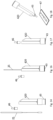
nach den Figuren 12 bei einem dritten Anwendungsschritt;bis 15 Figur 19- eine fünfte Ausführungsform einer Testanordnung nach der Erfindung;
Figur 20- einen Längsschnitt durch einen Applikator der Testanordnung nach
Figur 19 ; Figur 21- eine sechste Ausführungsform einer Testanordnung nach der Erfindung;
Figur 22- einen Längsschnitt durch einen Applikator der Testanordnung nach
Figur 21 ; Figur 23- eine perspektivische Ansicht einer siebten Ausführungsform einer Testanordnung nach der Erfindung;
Figur 24- die
Testanordnung nach Figur 23 im zur Benutzung vorbereiteten Zustand; Figur 25- eine Seitenansicht der Testanordnung nach
Figur 23 ; Figur 26- einen Schnitt durch die
Testanordnung nach Figur 23 entlang der Linie A-A inFigur 25 Figur 27- eine zweite Seitenansicht der Testanordnung nach
Figur 23 ; Figur 28- einen Schnitt durch die
Testanordnung nach Figur 23 entlang der Linie B-B inFigur 27 Figur 29einen Figur 28 entsprechenden Schnitt der Testanordnung nachFigur 23 , jedoch bei geschlossenem Auslassventil;Figur 30- eine perspektivische Ansicht einer achten Ausführungsform einer Testanordnung nach der Erfindung;
- Figur 31
- die
Testanordnung nach Figur 30 im anwendungsbereiten Zustand; Figur 32- einen Längsschnitt durch die
Testanordnung nach Figur 30 ; Figur 33- eine perspektivische Ansicht einer neunten Ausführungsform einer Testanordnung nach der Erfindung;
Figur 34- die
Testanordnung nach Figur 33 im anwendungsbereiten Zustand; Figur 35- einen Längsschnitt durch die
Testanordnung nach Figur 33 ; - Figur 36
- eine perspektivische Ansicht einer zehnten Ausführungsform einer Testanordnung nach der Erfindung;
Figur 37- die
Testanordnung nach Figur 37 im anwendungsbereiten Zustand; Figur 38- einen Längsschnitt durch die Testanordnung nach
Figur 36 ; Figur 39- eine perspektivische Ansicht einer elften Ausführungsform einer Testanordnung nach der Erfindung;
Figur 40- eine Seitenansicht der Testanordnung nach
Figur 39 ; Figur 41- einen Schnitt durch die Testanordnung
nach den Figuren 39 ;und 40 Figur 42- eine perspektivische Ansicht einer zwölften Ausführungsform einer Testanordnung nach der Erfindung; und
Figur 43- einen Längsschnitt durch die
Testanordnung nach Figur 42 bei der Benutzung.
- Figure 1
- a perspective top view of a first embodiment of the test arrangement according to the invention;
- Figure 2
- the individual parts of the test arrangement
Figure 1 ; - Figure 3
- a side view of the test arrangement after
Figure 1 ; - Figure 4
- a longitudinal section through the test arrangement according to
Figure 1 along line AA inFigure 3 ; - Figure 5
- a perspective view of a second embodiment of the test arrangement according to the invention;
- Figure 6
- the individual parts of the test arrangement
Figure 5 ; - Figure 7
- a side view of the test arrangement after
Figure 5 ; - Figure 8
- a cross-section of the test arrangement
Figure 5 along line AA inFigure 7 ; - Figure 9
- a perspective view of a third embodiment of the test arrangement according to the invention;
- Figure 10
- the individual parts of the test arrangement
Figure 9 ; - Figure 11
- a longitudinal section through the test arrangement according to
Figure 9 ; - Figure 12
- a perspective view of a fourth embodiment of the test arrangement according to the invention;
- Figure 13
- the test arrangement according to
Figure 12 in the delivery condition; - Figure 14
- a side view of the test arrangement after
Figure 12 ; - Figure 15
- a longitudinal section through the test arrangement;
- Figure 16
- the test arrangement according to the
Figures 12 to 15 in a first application step; - Figure 17
- the test arrangement according to the
Figures 12 to 15 in a second application step; - Figure 18
- the test arrangement according to the
Figures 12 to 15 in a third application step; - Figure 19
- a fifth embodiment of a test arrangement according to the invention;
- Figure 20
- a longitudinal section through an applicator of the test arrangement according to
Figure 19 ; - Figure 21
- a sixth embodiment of a test arrangement according to the invention;
- Figure 22
- a longitudinal section through an applicator of the test arrangement according to
Figure 21 ; - Figure 23
- a perspective view of a seventh embodiment of a test arrangement according to the invention;
- Figure 24
- the test arrangement according to
Figure 23 in a state prepared for use; - Figure 25
- a side view of the test arrangement after
Figure 23 ; - Figure 26
- a cross-section of the test arrangement
Figure 23 along the line AA inFigure 25 ; - Figure 27
- a second side view of the test arrangement after
Figure 23 ; - Figure 28
- a cross-section of the test arrangement
Figure 23 along the line BB inFigure 27 with the exhaust valve open; - Figure 29
- a
Figure 28 corresponding section of the test arrangement according toFigure 23 , but with the exhaust valve closed; - Figure 30
- a perspective view of an eighth embodiment of a test arrangement according to the invention;
- Figure 31
- the test arrangement according to
Figure 30 in ready-to-use condition; - Figure 32
- a longitudinal section through the test arrangement according to
Figure 30 ; - Figure 33
- a perspective view of a ninth embodiment of a test arrangement according to the invention;
- Figure 34
- the test arrangement according to
Figure 33 in ready-to-use condition; - Figure 35
- a longitudinal section through the test arrangement according to
Figure 33 ; - Figure 36
- a perspective view of a tenth embodiment of a test arrangement according to the invention;
- Figure 37
- the test arrangement according to
Figure 37 in ready-to-use condition; - Figure 38
- a longitudinal section through the test arrangement according to
Figure 36 ; - Figure 39
- a perspective view of an eleventh embodiment of a test arrangement according to the invention;
- Figure 40
- a side view of the test arrangement after
Figure 39 ; - Figure 41
- a cross-section of the test arrangement according to the
Figures 39 and 40 ; - Figure 42
- a perspective view of a twelfth embodiment of a test arrangement according to the invention; and
- Figure 43
- a longitudinal section through the test arrangement according to
Figure 42 when using it.
In den
Die Testanordnung 10 umfasst des Weiteren ein Test- bzw. Substanzsammelstäbchen 25, das einen Schaft 26 und einen Aufnahmebereich 27 aufweist. Der Schaft 26 ist mit seinem Endbereich formschlüssig von einer Schaftaufnahme 28 aufgenommen, welche an dem Kopplungsabschnitt 22 der Kunststoffhülse 12 ausgebildet ist. Bezogen auf die Mittelachse der Testanordnung ist das Testsammelstäbchen 25 exzentrisch, d.h. in radialer Richtung versetzt angeordnet.The
Der Kopplungsabschnitt 12 bildet zudem einen Boden 29 der Kunststoffhülse 12 aus, in dem eine Transferöffnung 30 ausgebildet ist, die in einen parallel zu dem Schaft 26 des Testsammelstäbchens 25 verlaufenden Kanal 31 führt, der wiederum in den Mischraum 21 des Behälters 2 mündet. Über die Transferöffnung 30 und den Kanal 31 ist eine Verbindung zwischen dem Aufnahmebereich 19 der Kunststoffhülse 12 und dem Mischraum 21 des aus Kunststoff oder Glas gefertigten Behälters 20 hergestellt.The
Drückbereiche 32 und 33 der Kunststoffhülse 12 stellen eine Aktivierungseinrichtung dar, mittels der die Glasampulle 14 geöffnet werden kann bzw. deren Spitzen 16 und 17 abgebrochen werden können.
Bei einer Anwendung der Testanordnung 10 wird mittels des an der Kunststoffhülse 12 befestigten Testsammelstäbchens 25 eine Oberfläche überstrichen, so dass Material aufgenommen wird, das gegebenenfalls die nachzuweisende Substanz umfasst. Anschließend wird der Behälter 20 mit der Kunststoffhülse 12 gekoppelt, das heißt an dem Kopplungsabschnitt 22 in der in
In den
Des Weiteren umfasst die Kunststoffhülse 12 der Testanordnung 200 einen Bodenbereich 35, in den die Spitze 16 der Ampulle 15 eingreift und der mit mehreren Transferöffnungen 30 versehen ist, die entlang einer die Spitze 16 umlaufenden Kreislinie verteilt sind und die den Aufnahmeraum 19 der Kunststoffhülse 12 mit dem Mischraum 21 des Behälters 20 verbinden. Zudem weist die Kunststoffhülse 12 entgegen der Ausführungsform nach den
Im Übrigen entspricht die Testanordnung 200 derjenigen nach den
In den
Der Schaft 26 des Testsammelstäbchens 25 ist in eine röhrchenartigen Schaftaufnahme 28 eingeschoben, welcher ebenfalls an dem Kopplungsabschnitt 22 der Kunststoffhülse 12 ausgeformt ist.The
Anschließend an die Schaftaufnahme 28 ist an der Kunststoffhülse 12 eine innenliegende Wand 37 ausgeformt, welche einer Kegelfläche folgt und an der umlaufend mehrere fensterartige Transferöffnungen 30 ausgeformt sind, welche eine Verbindung zwischen einem Aufnahmeraum 19 der Kunststoffhülse 12 und einem Mischraum 21 des Behälters 20 herstellen.Adjacent to the
Die Testanordnung 300 ist des Weiteren mit einer Aktivierungseinrichtung 38 versehen, die einerseits einen Betätigungsknopf 39 umfasst, der verschiebbar in der Kunststoffhülse 12 gelagert ist und innenseitig eine insbesondere ebene Rampe 40 aufweist, die zum Abbrechen der Spitze 17 der Ampulle 14 dient. Andererseits umfasst die Aktivierungseinrichtung 38 eine an einem Vorsprung 41 ausgebildete Rampe 42, welche zum Abbrechen der Spitze 16 der Ampulle 14 dient.The
Entsprechend der Anwendung der Testanordnungen nach den
In den
Des Weiteren umfasst das Gehäuse 42 einen Einsatz 43, welcher einen Behälter 20 darstellt, in dem ein Mischraum 21 ausgebildet ist. Der Einsatz 43 ist gegenüber einem die Kunststoffhülse 12 bildenden Gehäuseabschnitt 44 des Gehäuses 42 verlagerbar. Insbesondere kann der Einsatz 43 in den Gehäuseabschnitt 44 gedrückt werden, um die Testanordnung 400 zu aktivieren.Furthermore, the
Zur Ausbildung einer Aktivierungseinrichtung weist der Einsatz 43 eine Rampe 42 auf, welche mit der Spitze 16 der Ampulle zusammenwirkt. Die dem Einsatz 43 abgewandte Stirnseite der Kunststoffhülse 12, die von dem Gehäuseabschnitt 44 gebildet ist, bildet ebenfalls eine Rampe 40 aus, welche mit der Spitze 17 der Ampulle 14 zusammenwirkt. Der Einsatz 43, der den Behälter 20 bildet, ist also auch Bestandteil der Aktivierungseinrichtung.To form an activation device, the
Der Gehäuseabschnitt 44, der in dem Aufnahmeraum 19 die Ampulle 14 aufnimmt, bildet parallel zu dem Aufnahmeraum 19 einen Kanal 45 aus, über den einerseits ein Testsammelstäbchen 25, an dem ein Aufnahmebereich 27 ausgebildet ist, in den Mischraum 21 eingeführt werden kann und andererseits eine in den Mischraum 21 enthaltene Testflüssigkeit mittels einer Dosierkappe 46, die in ein stirnseitiges Ende des Kanals 45 einsetzbar ist, auf eine Testkassette 46, die mit einem Indikatorstreifen versehen ist, aufgebracht werden kann.The
Die Anwendung der Testanordnung 400 erfolgt derart, dass zunächst mittels des Testsammelstäbchens 25 eine Probe gewonnen wird. Anschließend wird das Aufnahmegehäuse 420 aktiviert, indem der Einsatz 43 in den Gehäuseabschnitt 44 eingedrückt wird. Dadurch werden mittels der Rampen 40 und 42 die Spitzen 15 und 17 der Ampulle 14 abgebrochen und die in der Ampulle 14 vorgehaltene Testflüssigkeit in den Mischraum 21 freigegeben. Das Testsammelstäbchen 25 wird über den Kanal 45 in den Mischraum 20 eingetaucht, so dass das auf dem Aufnahmebereich 27 angeordnete Material mit der Testflüssigkeit reagieren kann (vgl.
In den
Getrennt von dem Kunststoffröhrchen 510 umfasst die Testanordnung 500 einen Behälter 20, der nach Art eines kleinen Trogs ausgebildet ist und einen Mischraum 21 aufweist. Zudem umfasst die Testanordnung 500 ein Testsammelstäbchen 25 mit einem Aufnahmebereich 27.Separate from the
Des Weiteren ist eine Testkassette 47 mit einem Test- bzw. Indikatorstreifen vorgesehen.Furthermore, a
Das Kunststoffröhrchen 510 umfasst als Aktivierungseinrichtung zum Abbrechen der Spitzen 16 und 17 der Ampulle 15 definierte Drückbereiche 32 und 33, über die ein Nutzer die Spitzen 16 und 17 zur Freigabe der in der Ampulle 14 vorgehaltenen Testflüssigkeit abbrechen kann.The
Bei der Anwendung der Testanordnung 500 wird zunächst mittels des Testsammelstäbchens 25 eine Oberfläche bzw. ein Gewebe überstrichen, um ein Probe bzw. Material zu sammeln. Anschließend wird über die Drückbereiche 32 und 33 die Ampulle 14 aufgebrochen, so dass die Testflüssigkeit in einen Innenraum 53 des Pipettierabschnitts 50 des Kunststoffröhrchens 10 fließt. Dann wird die Testflüssigkeit durch manuelles Drücken des Balgbereichs 51 über die Pipettierspitze 52 in den Mischraum 21 des Behälters 22 gegeben. Daraufhin wird das Testsammelstäbchen 25 mit seinem Aufnahmebereich 27 in die Testflüssigkeit in dem Mischraum 21 getaucht. Nach einer definierten Verweilzeit wird das Testsammelstäbchen 25 wieder entfernt und die mit der Probe versetzte Testflüssigkeit in den Pipettierabschnitt 50 des Kunststoffröhrchens 510 gezogen. Diese kann dann definiert tröpfchenweise auf die Testkassette 47 gegeben werden. Kommt es dann an dem Teststreifen der Testkassette zu einem zumindest bereichsweisen Farbumschlag, ist eine bestimmte in der Probe enthaltene Substanz nachgewiesen. Ohne Farbumschlag liegt kein Nachweis vor.When using the
In den
Die Anwendung und Nutzung der Testanordnung 600 entspricht derjenigen der Testanordnung nach den
In den
Im zusammengesetzten Zustand der Testanordnung 700 ist in die Ringwand 60 der Testanordnung 700 eine Kunststoffhülse 12 eingesteckt, welche mit einem Kopplungsabschnitt 22 versehen ist, der eine Ringwand 61 aufweist, deren Außendurchmesser mit dem Innendurchmesser der Ringwand 60 des Behälters 20 korrespondiert. Die Kunststoffhülse 12 bildet einen Aufnahmeraum 19 für eine Ampulle 14, welche ebenfalls zwei Spitzen 16 und 17 aufweist, welche einen zylindrischen Ampullenkörper 15 endseitig begrenzen.In the assembled state of the
Als Aktivierungseinrichtung umfasst die Testanordnung 700 einen Betätigungsknopf 39, der in den Aufnahmeraum 19 der Kunststoffhülse 12 eindrückbar ist und innenseitig eine Rampe 40 aufweist, die mit der Spitze 17 der Ampulle 14 zusammenwirkt. An der dem Betätigungsknopf 39 abgewandten Seite weist die Kunststoffhülse 12 im Bereich des Kopplungsabschnitts 22 eine weitere Rampe 42 auf, welche mit der anderen Spitze 16 der Ampulle 14 zusammenwirkt.As an activation device, the
Zwischen dem Mischraum 21 und der Testkassette 47 der Testanordnung 700 liegt ein Transferkanal 62, welcher mittels eines manuell betätigbaren Schieberventils 63 wahlweise geöffnet oder geschlossen werden kann.Between the mixing
Zudem ist an der Testkassette 47 ein Behälter 64 für Referenzflüssigkeit angeordnet. Durch axialen senkrechten Druck auf den Behälter 64 kann die in diese enthaltene Referenzflüssigkeit in Richtung des Teststreifens der Testkassette 47 freigegeben werden.In addition, a
Bei der Anwendung der Testanordnung 700 zum Nachweis einer chemischen und/oder biologischen Substanz wird zunächst die Kunststoffhülse 12 von dem Behälter 20 abgenommen. Anschließend kann der Anwender sein Sputum oder auch eine andere Probe von oben in den Mischraum 21 des Behälters 20 einbringen. Dann wird die Kunststoffhülse 12 wieder auf den Behälter 20 aufgesetzt. Im Anschluss hieran drückt der Anwender in axialer Richtung auf den Betätigungsknopf 39, so dass die Spitzen 16 und 17 der Ampulle 14 abgebrochen werden und die in dieser enthaltene Testflüssigkeit nach unten in den Mischraum 21 fließt und sich mit dem Sputum vermengt. Nach einer insbesondere definierten Verweilzeit wird das Schieberventil 63 betätigt, so dass der Fluidfluss zwischen dem Mischraum 21 und der Testkassette 47 freigegeben ist und mittels des Teststreifens der Testkassette 47 ermittelbar ist, ob ein bestimmter Stoff, beispielsweise ein Virus, in dem Sputum vorhanden ist. Der Nachweis erfolgt dadurch, dass der Teststreifen einen Farbumschlag erfährt. Gegebenenfalls kann durch Drücken des Behälters 64 das Testergebnis mittels der Referenzflüssigkeit überprüft werden.When using the
In den
Bei der Benutzung der Testanordnung 800 nimmt der Anwender zunächst die Kunststoffhülse 12 von dem Behälter 20 ab, so dass er Sputum oder auch eine andere Probe in den Mischraum 21 des Behälters 20 einbringen kann. Anschließend setzt er die Kunststoffhülse 12 wieder in den Behälter 20 ein, so dass eine Ringwand 61 der Kunststoffhülse 12 an einer korrespondierenden Ringwand des Behälters 20 von innen anliegt. Die Einschubtiefe ist durch einen Ringbund 67 festgelegt, welcher an der Kunststoffhülse 12 ausgeformt ist.When using the
Dann drückt der Anwender auf die eine Aktivierungseinrichtung darstellenden Drückbereiche 32 und 33, so dass die Spitzen 16 und 17 der Ampulle 14 abgebrochen werden und die Testflüssigkeit aus der Ampulle 14 in den Mischraum 21 fließt und sich dort mit dem Sputum vermengt. Der Mischprozess kann gegebenenfalls durch Schütteln der Anordnung unterstützt werden. Anschließend wird die Kappe 66 abgenommen und das Gemisch aus der Testflüssigkeit und dem Sputum auf die Testkassette 47 dosiert. Bei Vorliegen einer bestimmten Substanz, beispielsweise eines Virus in dem Sputum, erfährt der Teststreifen der Testkassette 47 zumindest bereichsweise einen Farbumschlag. Somit ist ein Nachweis dieser Substanz, d.h. des Virus, möglich.The user then presses on the
In den
Hinsichtlich des Aufbaus entspricht die Testanordnung 900 im Übrigen derjenigen nach den
Bei der Nutzung wird aber anders als bei der Testanordnung nach den
In den
Im Übrigen entsprechen der Aufbau und die Anwendung der Anordnung 1000 dem Aufbau und der Anwendung der Testanordnung nach den
In den
An der dem Behälter 20 abgewandten Seite weist die Kunststoffhülse 12 als Aktivierungseinrichtung einen Betätigungsknopf 39 auf, der innenseitig mit einer Rampe 40 versehen ist, welche mit einer Spitze 17 der Ampulle 14 zusammenwirkt. An der dem Betätigungsknopf 39 abgewandten Seite weist die Kunststoffhülse 12 eine Rampe 42 auf, die von einer Bodenfläche gebildet ist.On the side facing away from the
Zudem ist die Testanordnung 1100 mit einem Testsammelstäbchen 25 versehen, das ebenfalls einen Aufnahmebereich 27 aufweist.In addition, the
Bei der Anwendung wird mittels des Testsammelstäbchens 25 eine Probe von einer Oberfläche oder einem Gewebe gewonnen. Dann wird der Betätigungsknopf 39 nach unten gedrückt, so dass mittels der Rampen 40 und 42 die Spitzen 16 und 17 der Ampulle 14 abbrechen und die in der Ampulle 14 enthaltene Testflüssigkeit über eine Transferöffnung 30 aus der Kunststoffhülse 12 in den Mischraum 21 des Behälters 20 fließt. Dann wird das Testsammelstäbchen 25 mit seinem Aufnahmebereich 27 in die Testflüssigkeit in dem Mischraum 21 getaucht, gegebenenfalls unter Rühren.During use, a sample is taken from a surface or tissue using the
Anschließend kann die Testflüssigkeit über den Ausguss 70 auf eine Testkassette 47 mit Teststreifen dosiert werden, so dass der Nachweis einer mittels des Testsammelstäbchens 25 aufgenommenen Substanz möglich ist. Erfolgt ein Farbumschlag an dem Teststreifen, ist die Substanz nachgewiesen. Ohne Farbumschlag kann der Nachweis nicht erbracht werden.The test liquid can then be dosed via the
In den
Zudem weist die Testanordnung 1200 oben einen Einsatz 72 auf, der einerseits in Form einer Rampe 40 mit einer Aktivierungseinrichtung versehen ist und andererseits mit einem Ausguss 70 versehen ist. Die Rampe 40 ist durch eine innenliegende, schräg angestellte Trennwand gebildet.In addition, the test arrangement 1200 has an
An der dem in der Kunststoffhülse 12 axial verlagerbaren Einsatz 72 abgewandten Seite weist der Behälter 20 durch ein schräg angestellte Begrenzungswand des Mischraums 21 eine weitere Rampe 42 auf, die mit der Spitze 16 der Ampulle 14 zusammenwirkt.On the side facing away from the
Der Durchmesser der Kunststoffhülse 12 ist so gewählt, dass über den röhrchenartigen Einsatz 72 ein Testsammelstäbchen 25 mit seinem Aufnahmebereich 27 an der Ampulle vorbei in den Mischraum 21 eingebracht werden kann, der Außendurchmesser der Ampulle 15 ist also kleiner als der Innendurchmesser der Kunststoffhülse 12.The diameter of the
Bei der Anwendung der Testanordnung 1200 wird zunächst mittels des Testsammelstäbchens 25 eine Probe gewonnen. Das Testsammelstäbchen 25 wird dann in der vorstehend beschriebenen Weise über den Einsatz 72 und den Freiraum zwischen der Ampulle 14 und der Umfangswand der Kunststoffhülse 12 mit seinem Aufnahmebereich 27 in den Mischraum 21 eingeführt. Anschließend wird der Einsatz 72 in die Kunststoffhülse 12 gedrückt, so dass mittels der Rampen 40 und 42 die Spitzen 16 und 17 der Ampulle 14 abgebrochen werden und die in der Ampulle 14 vorgehaltene Testflüssigkeit in den Mischraum 21 fließt. Insbesondere nach einer definierten Verweilzeit kann dann das Testsammelstäbchen 25 entfernt werden und die Testflüssigkeit über den Ausguss 70 auf eine Testkassette 47 dosiert werden. Bei Vorhandensein der nachzuweisenden Substanz in der Probe erfährt der Teststreifen der Testkassette 47 einen Farbumschlag. Im anderen Fall erfolgt kein Farbumschlag.When using the test arrangement 1200, a sample is first obtained using the
- 1010
- Testanordnungtest setup
- 1212
- Kunststoffhülseplastic sleeve
- 1414
- Glasampulleglass ampoule
- 1515
- Ampullenkörperampoule body
- 1616
- SpitzeGreat
- 1717
- SpitzeGreat
- 1818
- Sollbruchstelllepredetermined breaking point
- 1919
- Aufnahmeraumrecording room
- 2020
- Behältercontainer
- 2121
- Mischraummixing room
- 2222
- Kopplungsabschnittcoupling section
- 2323
- SchürzeApron
- 2424
- Ringwandring wall
- 2525
- Testsammelstäbchentest swabs
- 2626
- Schaftshaft
- 2727
- Aufnahmebereichrecording area
- 2828
- Schaftaufnahmeshaft mount
- 2929
- BodenFloor
- 3030
- Transferöffnungtransfer opening
- 3131
- Kanalchannel
- 3232
- Drückbereichpressure range
- 3333
- Drückbereichpressure range
- 3434
- Endabschnittfinal section
- 3535
- Bodenbereichfloor area
- 3636
- Ringbundring band
- 3737
- WandWall
- 3838
- Aktivierungseinrichtungactivation device
- 3939
- Betätigungsknopfoperating button
- 4040
- Ramperamp
- 4141
- Vorsprungprojection
- 4242
- Ramperamp
- 4343
- EinsatzMission
- 4444
- Gehäuseabschnitthousing section
- 4545
- Kanalchannel
- 4646
- Dosierkappedosing cap
- 4747
- Testkassettetest cassette
- 5050
- Pipettierabschnittpipetting section
- 5151
- Balgbereichbellows area
- 5252
- Pipettierspitzepipette tip
- 6060
- Ringwandring wall
- 6161
- Ringwandring wall
- 6262
- Transferkanaltransfer channel
- 6363
- Schieberventilslide valve
- 6464
- Behältercontainer
- 6565
- Austragöffnungdischarge opening
- 6666
- Kappe/Verschlusscap/closure
- 6767
- Ringbundring band
- 7070
- Ausgussspout
- 7171
- Fußabschnittfoot section
- 7272
- EinsatzMission
- 200200
- Tetsanordnungtest order
- 300300
- Testanordnungtest setup
- 400400
- Testanordnungtest setup
- 420420
- Aufnahmegehäusehousing
- 500500
- Testanordnungtest setup
- 510510
- Kunststoffröhrchenplastic tubes
- 600600
- Testanordnungtest setup
- 700700
- Testanordnungtest setup
- 800800
- Testanordnungtest setup
- 900900
- Testanordnungtest setup
- 10001000
- Testanordnungtest setup
- 11001100
- Testanordnungtest setup
- 12001200
- Testanordnungtest setup
Claims (15)
Priority Applications (2)
| Application Number | Priority Date | Filing Date | Title |
|---|---|---|---|
| EP23165995.4A EP4438177A1 (en) | 2023-03-31 | 2023-03-31 | Test arrangement for detecting a substance |
| US18/617,877 US20240327096A1 (en) | 2023-03-31 | 2024-03-27 | Test Arrangement for the Detection of a Substance |
Applications Claiming Priority (1)
| Application Number | Priority Date | Filing Date | Title |
|---|---|---|---|
| EP23165995.4A EP4438177A1 (en) | 2023-03-31 | 2023-03-31 | Test arrangement for detecting a substance |
Publications (1)
| Publication Number | Publication Date |
|---|---|
| EP4438177A1 true EP4438177A1 (en) | 2024-10-02 |
Family
ID=85800246
Family Applications (1)
| Application Number | Title | Priority Date | Filing Date |
|---|---|---|---|
| EP23165995.4A Pending EP4438177A1 (en) | 2023-03-31 | 2023-03-31 | Test arrangement for detecting a substance |
Country Status (2)
| Country | Link |
|---|---|
| US (1) | US20240327096A1 (en) |
| EP (1) | EP4438177A1 (en) |
Citations (6)
| Publication number | Priority date | Publication date | Assignee | Title |
|---|---|---|---|---|
| US3792699A (en) * | 1972-05-30 | 1974-02-19 | Medex Inc | Disposable swab unit |
| US20030064526A1 (en) * | 2001-09-28 | 2003-04-03 | Orasure Technologies, Inc. | Sample collector and test device |
| US20160116379A1 (en) * | 2014-10-22 | 2016-04-28 | Ibis Biosciences, Inc. | Apparatuses for sterilely delivering fluid |
| CN112236239A (en) * | 2018-05-16 | 2021-01-15 | 塞茨希默萨加罗民法公司(授权代表:安德烈亚斯·希默,阿伦斯堡22926;阿尔伯托·C.·萨加罗,巴特洪堡61348;塞巴斯蒂安·塞茨,德尔旺根91602) | Applicator device |
| US20210291181A1 (en) * | 2020-03-17 | 2021-09-23 | Detect, Inc. | Seal component for a rapid diagnostic test |
| US20220155294A1 (en) * | 2020-11-13 | 2022-05-19 | Detect, Inc. | Apparatuses for performing rapid diagnostic tests |
-
2023
- 2023-03-31 EP EP23165995.4A patent/EP4438177A1/en active Pending
-
2024
- 2024-03-27 US US18/617,877 patent/US20240327096A1/en active Pending
Patent Citations (6)
| Publication number | Priority date | Publication date | Assignee | Title |
|---|---|---|---|---|
| US3792699A (en) * | 1972-05-30 | 1974-02-19 | Medex Inc | Disposable swab unit |
| US20030064526A1 (en) * | 2001-09-28 | 2003-04-03 | Orasure Technologies, Inc. | Sample collector and test device |
| US20160116379A1 (en) * | 2014-10-22 | 2016-04-28 | Ibis Biosciences, Inc. | Apparatuses for sterilely delivering fluid |
| CN112236239A (en) * | 2018-05-16 | 2021-01-15 | 塞茨希默萨加罗民法公司(授权代表:安德烈亚斯·希默,阿伦斯堡22926;阿尔伯托·C.·萨加罗,巴特洪堡61348;塞巴斯蒂安·塞茨,德尔旺根91602) | Applicator device |
| US20210291181A1 (en) * | 2020-03-17 | 2021-09-23 | Detect, Inc. | Seal component for a rapid diagnostic test |
| US20220155294A1 (en) * | 2020-11-13 | 2022-05-19 | Detect, Inc. | Apparatuses for performing rapid diagnostic tests |
Also Published As
| Publication number | Publication date |
|---|---|
| US20240327096A1 (en) | 2024-10-03 |
Similar Documents
| Publication | Publication Date | Title |
|---|---|---|
| DE60306232T2 (en) | Cotton ball device and procedure | |
| DE69032623T2 (en) | SAMPLE TEST UNIT | |
| DE69837476T2 (en) | Multi-chamber dispenser with a deformable housing | |
| DE69219612T2 (en) | Testing device | |
| DE69210239T2 (en) | SAMPLING DEVICE | |
| DE60300304T2 (en) | Extractor tube for collecting stool samples | |
| DE69925210T2 (en) | Tip for a suction device | |
| DE2638743C3 (en) | Device for dispensing a biological fluid | |
| DE2525340A1 (en) | ELEVATOR ARRANGEMENT FOR A DEVICE FOR DILUTING LIQUID SAMPLES | |
| WO2003068398A1 (en) | Sample preparation device and test device set based thereon | |
| DE2603616A1 (en) | PIPETTE ARRANGEMENT FOR INDIVIDUAL ANALYZES | |
| WO2007093150A1 (en) | Method and device for withdrawing a volume of liquid by suction, in particular for collecting a sample for analysis by means of a liquid chromatography device | |
| DE10011235C2 (en) | Stitching device for sample taking and method for taking a sample | |
| DE19539276A1 (en) | Apparatus for dispensing fluid in small amounts from sample container | |
| EP1838239A1 (en) | Testing unit for carrying out a one-time testing of a body fluid | |
| DE69921051T2 (en) | Suction device for dispensing liquids | |
| DE69111394T2 (en) | Disposable device for testing a liquid. | |
| DE3415580C2 (en) | ||
| EP2764918A1 (en) | Device for analysing a test fluid | |
| EP4438177A1 (en) | Test arrangement for detecting a substance | |
| EP3248683B1 (en) | Capillary draining aid | |
| EP0907414B1 (en) | Method for achieving chemical, in particular biochemical reactions and pipette tip with reaction vessel | |
| DE102013000922A1 (en) | Autonomous samplers for biological fluids in system, has sampling body, which is formed hollow-cylindrical and is combined in region of its inner surface with intermediate piece | |
| WO1998058587A1 (en) | Device for taking and examining samples | |
| DE60211743T2 (en) | PIPETTE AND METHOD FOR TESTING LIQUID FLUIDS |
Legal Events
| Date | Code | Title | Description |
|---|---|---|---|
| STAA | Information on the status of an ep patent application or granted ep patent |
Free format text: STATUS: UNKNOWN |
|
| PUAI | Public reference made under article 153(3) epc to a published international application that has entered the european phase |
Free format text: ORIGINAL CODE: 0009012 |
|
| STAA | Information on the status of an ep patent application or granted ep patent |
Free format text: STATUS: THE APPLICATION HAS BEEN PUBLISHED |
|
| AK | Designated contracting states |
Kind code of ref document: A1 Designated state(s): AL AT BE BG CH CY CZ DE DK EE ES FI FR GB GR HR HU IE IS IT LI LT LU LV MC ME MK MT NL NO PL PT RO RS SE SI SK SM TR |
|
| STAA | Information on the status of an ep patent application or granted ep patent |
Free format text: STATUS: REQUEST FOR EXAMINATION WAS MADE |
|
| 17P | Request for examination filed |
Effective date: 20250326 |