EP4268648B1 - Protective device for a hand - Google Patents
Protective device for a hand Download PDFInfo
- Publication number
- EP4268648B1 EP4268648B1 EP22170087.5A EP22170087A EP4268648B1 EP 4268648 B1 EP4268648 B1 EP 4268648B1 EP 22170087 A EP22170087 A EP 22170087A EP 4268648 B1 EP4268648 B1 EP 4268648B1
- Authority
- EP
- European Patent Office
- Prior art keywords
- finger
- palm
- protection
- finger protection
- protective device
- Prior art date
- Legal status (The legal status is an assumption and is not a legal conclusion. Google has not performed a legal analysis and makes no representation as to the accuracy of the status listed.)
- Active
Links
Images




Classifications
-
- A—HUMAN NECESSITIES
- A41—WEARING APPAREL
- A41D—OUTERWEAR; PROTECTIVE GARMENTS; ACCESSORIES
- A41D13/00—Professional, industrial or sporting protective garments, e.g. surgeons' gowns or garments protecting against blows or punches
- A41D13/05—Professional, industrial or sporting protective garments, e.g. surgeons' gowns or garments protecting against blows or punches protecting only a particular body part
- A41D13/08—Arm or hand
- A41D13/081—Hand protectors
- A41D13/082—Hand protectors especially for the inner part of the hand
-
- A—HUMAN NECESSITIES
- A41—WEARING APPAREL
- A41D—OUTERWEAR; PROTECTIVE GARMENTS; ACCESSORIES
- A41D13/00—Professional, industrial or sporting protective garments, e.g. surgeons' gowns or garments protecting against blows or punches
- A41D13/05—Professional, industrial or sporting protective garments, e.g. surgeons' gowns or garments protecting against blows or punches protecting only a particular body part
- A41D13/08—Arm or hand
- A41D13/081—Hand protectors
- A41D13/087—Hand protectors especially for fingers
-
- A—HUMAN NECESSITIES
- A41—WEARING APPAREL
- A41D—OUTERWEAR; PROTECTIVE GARMENTS; ACCESSORIES
- A41D19/00—Gloves
- A41D19/0055—Plastic or rubber gloves
- A41D19/0058—Three-dimensional gloves
-
- A—HUMAN NECESSITIES
- A61—MEDICAL OR VETERINARY SCIENCE; HYGIENE
- A61B—DIAGNOSIS; SURGERY; IDENTIFICATION
- A61B42/00—Surgical gloves; Finger-stalls specially adapted for surgery; Devices for handling or treatment thereof
- A61B42/20—Finger-stalls specially adapted for surgery
-
- A—HUMAN NECESSITIES
- A41—WEARING APPAREL
- A41D—OUTERWEAR; PROTECTIVE GARMENTS; ACCESSORIES
- A41D19/00—Gloves
- A41D19/0055—Plastic or rubber gloves
- A41D19/0082—Details
- A41D19/0096—Means for resisting mechanical agressions, e.g. cutting or piercing
-
- A—HUMAN NECESSITIES
- A41—WEARING APPAREL
- A41D—OUTERWEAR; PROTECTIVE GARMENTS; ACCESSORIES
- A41D19/00—Gloves
- A41D19/015—Protective gloves
- A41D19/01547—Protective gloves with grip improving means
- A41D19/01558—Protective gloves with grip improving means using a layer of grip improving material
Definitions
- the invention relates to a protective device for a hand, which comprises exactly two finger protection elements and a palm protection element connecting the two finger protection elements, wherein one finger protection element is intended for the thumb and the other finger protection element for another finger, in particular the index finger, of a user and the palm protection element is designed to be flat so that it only comes into contact with the palm of a user, while the back of the user's hand remains free or essentially free.
- BGW health services and welfare
- finger cots that can be placed individually on the fingertips.
- these finger cots are often made of inadequate material, so that they do not offer sufficient protection against punctures and cuts in the finger area. Even protection limited to the fingers is sometimes considered inadequate.
- a surgical finger guard as a needlestick guard. It comprises an element that is flexible and resistant to a needle point.
- the element is designed to be conformable to a finger to provide a continuous barrier to a needle stick over at least a portion of the finger.
- the element has a continuous, undulating shape which ends with an end cap that is resistant to a needle point.
- the disclosed elements extend over individual fingers, analogous to finger cots.
- a surgical glove is made of a thin, elastic material that is designed to be resistant to nail punctures in selected areas on the palm of the hand.
- it includes suitable materials in these areas, for example a woven material or a solid material.
- the EP 0 320 541 A1 discloses another surgical glove that is resistant to needle sticks. It comprises a thin base glove made of latex or a synthetic rubber, which is provided on the inside with a reinforcement material with a tightly woven puncture-resistant reinforcement material to minimize the risk of punctures or tears.
- the DE 20 2006 010 706 U1 reveals finger cots and a partial glove to prevent cuts in hairdressing.
- the partial glove covers two of the user's fingers, specifically the index and middle fingers, the palm, the back of the hand and the wrist. It is made of a cut-resistant nitrile plastic or a metallic fabric that is coated with plastic.
- the protective devices known from the state of the art have in principle proven to be effective in protecting users' hands from injuries caused by pointed and sharp objects. However, there is still a need for improved devices. In particular, there is a need for protective devices that enable very safe and at the same time quick and convenient disposal of pointed or sharp medical objects after use.
- the protective device according to the invention when worn on the hand as intended - in contrast to classic "full gloves" - covers only part of the hand, specifically two fingers at least in sections and the palm.
- the fingers that the device according to the invention protects are the thumb and another finger, preferably the index finger.
- the structure is based on the typical hand movements that are carried out especially when closing or re-closing pointed and sharp medical utensils, such as cannulas, lancets, scalpels and the like.
- the securing or closing elements which can be covers or caps, are usually held between the thumb and another finger, in particular the index finger, while the previously used instrument is carefully inserted.
- the applicant has determined that the fingertips of the two fingers used for holding, but also the palm of the user's hand, are at risk of being injured, for example as a result of slipping or incorrect "aiming" during the insertion process.
- the device according to the invention reliably protects precisely these particularly vulnerable areas of the hand during the re-closing process.
- the protective device according to the invention can be put on very comfortably and particularly quickly by a user. All he has to do is insert the tips of his thumb and another finger, especially his index finger, into the respective finger protection element.
- the palm protection element connecting the two finger protection elements then lies protectively in front of his palm.
- the protective device according to the invention can be put on particularly quickly, especially in comparison with previously known full and partial gloves, which have to be pulled over the hand and up to the wrist with relative effort, the effort associated with disposal is minimized. If the effort of proper and at the same time safe disposal is low, users are more likely to opt for this and the risk of health risks is reduced.
- the protective device according to the invention can also be used in combination with thin disposable rubber gloves, which are often worn in the medical or nursing field. These do not have to be removed before the device according to the invention is put on. This will be the case with the previously known full or partial gloves with a protective function against punctures and cuts, since pulling another full or partial glove over an existing rubber glove is problematic. Since the protective device according to the invention does not require the disposable gloves to be removed, the effort can be further reduced.
- one of the finger protection elements is intended for the thumb and the other for another finger, in particular the index finger of a user's hand, means in particular or includes in particular that the elements are designed and arranged in such a way that one can be placed on the thumb and the other on another finger, in particular the index finger, of a user's hand. If the two finger protection elements are placed on the fingers, the protective device according to the invention is worn as intended.
- the finger protection elements are both located closer to one end region of the palm protection element than to another end region of the palm protection element opposite the one end region.
- the two finger protection elements can in particular be located directly on the one end region of the palm protection element.
- the other end region i.e. the end region on which the finger protection elements are not located or from which they are further away, is a free end region of the palm protection element.
- the palm protection element is preferably tongue-shaped.
- the palm protection element has an end region with a U-shaped outer contour, called the tip region, and an end region opposite the tip region, called the root region. Then the finger protection elements are both preferably located closer to the root region than to the tip region. They can be located directly on the root region.
- the tip area is preferably a free end area of the palm protection element.
- the root region ends with a straight edge opposite the tip region and that the finger protection elements extend up to this edge.
- the palm protection element then ends in the area of the finger protection elements or extends starting from the finger protection elements.
- This configuration has proven to be particularly suitable, particularly in the case where one of the finger protection elements is intended for the index finger.
- the thumb and index finger are both arranged close to or at an end region of the palm. In the case of the left hand, when looking at the palm, these are specifically located at the left end region of the palm and in the case of the right hand, at the right.
- the two finger protection elements are arranged to the side of the palm protection element in relation to the two opposite end regions of the palm protection element, preferably protruding laterally from the palm protection element.
- laterally means in particular to the side of the palm protection element in relation to an imaginary line connecting these two end regions.
- one of the two finger protection elements is arranged on two opposite sides of the palm protection element.
- the finger protection elements are open at one end and at the end opposite the open end other end are closed, with the open end facing the palm protection element and the closed end facing away from the palm protection element. Then the tips of the thumb and another finger, in particular the thumb and index finger, of one hand can be inserted into the finger protection elements in a particularly convenient manner in order to put on the protective device according to the invention.
- the thumb and index finger can be separated in a V shape, for example.
- the palm protection element then lies between the two finger protection elements and one end region of the latter, when worn, lies in particular on that end region of the palm of a user which connects the thumb and index finger and extends from there preferably over the entire palm of the user.
- the finger protection elements each comprise a finger protection cap with a closed top and an open bottom. It is also possible for the finger protection elements to be formed by such finger protection caps. Finger protection caps can be easily placed on the thumb and other fingers of a user and reliably protect the tips of these fingers in particular.
- the finger protection caps are preferably characterized at least essentially by the shape of a hollow truncated cone or at least essentially by the shape of a hollow cylinder closed on one side. These shapes have proven particularly useful for caps that can be placed on fingers. At least essentially means that deviations from the exact hollow truncated cone or hollow cylinder shape can exist.
- the finger protection caps can be rounded in particular, e.g. rounded edges and curved, especially convex, front walls, as is known from thimbles.
- the finger protection caps are characterized by a greater material thickness on their front sides than in the remaining area.
- the reinforcement of the material on the front side offers particularly high resistance in risk zones. When worn, the fingertips are located under the front sides, which are particularly at risk, especially when it comes to punctures.
- a further embodiment of the invention is characterized in that the finger protection elements have a finger protection bar. If such a bar is present, it is connected in particular to the open underside of the finger protection cap of the respective finger protection element.
- a finger protection bar can in particular serve to protect a lower section of the thumb and another finger, in particular the index finger, which is closer to the palm of the hand.
- the upper sections of the thumb and the other finger are covered and protected all around, while the lower sections of the fingers are only protected on their inside by the respective finger protection bar, but remain free on the outside or top and sides.
- the finger protection bars are preferably designed and arranged accordingly in order to cover and thus protect a longitudinal section of the respective finger, in particular only on the inside.
- the finger protection bars are preferably flat and only come into contact with the inside of the fingers, while leaving the fingers free on the outside or top and sides.
- the finger protection elements each comprise a finger protection bar
- the finger protection bar of the finger protection element intended for the thumb has a shorter length than the finger protection bar of the finger protection element intended for the other finger, in particular the index finger.
- finger protection elements are connected to one another exclusively via the palm protection element and are in particular formed in one piece. If the finger protection elements comprise finger protection caps and adjoining finger protection webs, the palm protection element is preferably connected to the finger protection webs.
- a fastening strap can be provided, one end of which is firmly connected to the palm protection element, preferably in the area which, in the intended state, is located between the base of the thumb and the base of the other finger, and the free end of which can be releasably fixed to the palm protection element, in particular to the area which is associated with the ball of a user's hand, for example by means of a Velcro fastener, after the fastening strap has been placed over the back of the user's hand.
- the palm protection element can be additionally fixed to the hand.
- Knobs can be provided on the inside and/or outside of the finger protection caps, which enables particularly safe handling of pointed or sharp utensils. Knobs on the inside of the finger protection caps ensure, above all, a particularly secure hold of the device according to the invention or the finger protection caps on the Hand of a user. External knobs allow more control when handling objects.
- the material thickness of the protective device according to the invention is expediently selected such that a sufficient degree of puncture or cut resistance is ensured.
- the material thickness of the finger protection caps is at least 1.0 mm, in particular at least 2.0 mm, at least in sections and/or the material thickness of the finger protection caps is a maximum of 5.0 mm, in particular a maximum of 4.0 mm, and preferably 3.0 mm.
- the material thickness of the finger protection bars is at least 1.0 mm, in particular at least 2.0 mm and/or a maximum of 5.0 mm, in particular a maximum of 4.0 mm and preferably 3.0 ⁇ 0.5 mm.
- the interior of the finger protection caps can have a diameter of 1.5 to 3.0 cm and/or a length in the range of 1.5 to 6.0 cm, particularly at their widest point. It is particularly preferred if the finger protection caps are designed in such a way that they only cover the front thumb or finger joint up to the first finger joint. In this case, the finger protection caps have a length of at least 2.0 cm, in particular at least 2.5 cm and/or of at most 4.0 cm, in particular at most 3.0 cm.
- the palm protection element is expediently designed and arranged in such a way that, when worn as intended, it Protective device when the two finger protection elements are each placed on a finger, in particular the thumb and index finger of a user, extending protectively in front of the user's palm. It can be designed as a flexible mat that lies between the two finger protection elements and, when worn, covers the palm of the hand and lies against it.
- the protective device according to the invention or its finger protection elements and/or palm protection element preferably comprise an elastically deformable material, in particular at least one elastomer or silicone, or consist thereof.
- the finger protection elements and/or the palm protection element can comprise or consist of latex. It is important that the palm protection element is sufficiently flexible so that it rests against the palm of the hand during use.
- the finger protection bars must also be flexible enough that the thumb and the other finger can be moved freely. This is ensured by appropriately matching the elasticity of the material used and the material thickness.
- the material can be reinforced. In particular, reinforcing elements such as strips of sheet metal, plastic or the like or reinforcing fibers can be embedded in the material.
- a further embodiment of the invention is characterized in that the palm protection element has a thickness of at least 1.0 mm, in particular at least 2.0 mm and/or a maximum of 5.0 mm, in particular a maximum of 4.0 mm, wherein the thickness is preferably 3.0 ⁇ 0.5 mm, and/or that the palm protection element has a length of at least 6.0 cm, in particular at least 7.0 cm and/or a maximum of 11.0 cm, in particular a maximum of 9.0 ⁇ 0.5 cm.
- the protective device according to the invention is designed in such a way that it leaves three fingers, preferably the ring finger, middle finger and little finger, and/or the back of the hand and/or the wrist free when a user wears it as intended. It has proven to be particularly suitable if it leaves three fingers, in particular the ring finger, middle finger and little finger, and the back of the hand and the wrist free. Particularly preferably, only the upper end areas of two fingers are covered by the two finger protection caps and the palm of the hand is covered by the palm protection element.
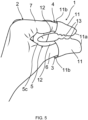
- FIGS 1 to 9 show various views of an embodiment of a protective device 1 according to the invention.
- Figures 1 to 7 the device 1 when worn on the hand 2 of a user while it Figures 8 and 9 can be removed in an unworn condition and is on its own.
- the protective device 1 comprises two finger protection elements 3, 4 and a palm protection element 5, which connects the two finger protection elements 3, 4 to one another.
- One finger protection element 3 is clearly intended for the thumb 6 and the other finger protection element 4 is clearly intended for the index finger 7 of the hand 2 of a user.
- the protective device 1 comprises exactly two finger protection elements 3, 4.
- the protective device 1 has no finger protection elements for the remaining fingers, i.e. the middle finger 8, ring finger 9 and little finger 10. These fingers 8, 9, 10 remain free when the device 1 is worn on the hand 2 of a user. The same applies to the back of the hand 2a and the wrist 2b, which also remain free.
- the protective device 1 has no protective elements for these either.
- the two finger protection elements 3, 4 for the thumb 6 and the index finger 7 each comprise a finger protection cap 11 and a finger protection bar 12 in the embodiment shown.
- the shape of the finger protection caps 11 corresponds to conventional thimbles that are also used for sewing. They have approximately the shape of hollow truncated cones, whereby the front end section of these is noticeably rounded and thus adapted to the shape of the fingertips to be accommodated.
- the caps 11 are closed on their front side 11a and their underside 11b opposite the front side is open so that they can be placed on the fingertip (see in particular the Figures 2 and 5 , which show the attached state particularly well).
- the length of the finger protection caps 11 is selected in such a way that, when worn, only an upper section of the thumb 6 or index finger 7 is received and covered, specifically only the section that extends from the fingertip to approximately the top joint of the respective finger 6, 7. The remaining section from the thumb and index finger to the palm is left free by the finger protection caps 11.
- the length of the interior of the finger protection caps 11 is 3.0 cm. The diameter of their interior is 2.5 cm at the widest point.
- the finger protection caps 11 are each connected to a finger protection bar 12 at the bottom, in other words starting at their open undersides, which protects the thumb 6 and index finger 7 over the remaining longitudinal section of the finger 6, 7 that is not covered by the finger protection cap 11 and extends to the metacarpal, but only in the area of the inner surface of the respective finger 6, 7. They are designed and arranged accordingly in order to only cover and protect the lower longitudinal section of the respective finger 6, 7, which extends from the top finger joint to the lower end of the finger 6, 7, on the inside. On the outside, back and sides, they leave the thumb 6 and index finger 7 free.
- the finger protection bars 12 here have an approximately rectangular outer circumference. They both have a width of 2.0 cm, but have different lengths.
- the finger protection bar 12 of the finger protection element 3 intended for the thumb 6 is shorter than the finger protection bar of the finger protection bar 12 intended for the index finger 7 in order to take into account the different lengths of these two fingers.
- the finger protection bars 12 are formed in one piece with the finger protection caps 11 and are molded onto them.
- the finger protection bars 12 and caps 11 consist of an elastic plastic material, in particular a Elastomer or silicone. They have a suitable material thickness to provide good protection against punctures, scratches, cuts and the like.
- the material thickness in the area of the front sides 11a of the finger protection caps 11 is 5.0 mm, while in the remaining areas of the finger protection caps 11 it is 3.0 mm.
- the front sides 11a of the finger protection caps 11 are therefore reinforced in order to provide particularly good protection in the risk zones there.
- the greater material thickness is shown in the sectional view in Figure 9 to recognize.
- the material thickness of the finger protection bars 12 is 3.0 mm.
- the finger protection elements 3, 4 have knobs 13 in the areas of the finger protection caps 11 that are adjacent to or border on the finger protection webs 12.
- the knobs 13 are provided on both the inside and outside of these areas of the finger protection caps 11.
- the knobs 13 are positioned on the side of the finger protection caps 11 that is also connected to the finger protection web 12 and that faces the palm protection element 5.
- the material thickness of the finger protection caps 4 is slightly reduced so that the tips of the inner knobs 13 are approximately flush with the inside of the finger protection webs 12.
- the inner knobs 13 ensure, above all, a particularly secure hold of the device according to the invention or of the finger protection caps 11 on the hand 2 of a user and the outer knobs 13 above all provide more control with regard to objects to be handled.
- the palm protection element 5 which is tongue-shaped here, connects the two finger protection elements 3, 4 of the device 1, specifically their Finger protection bars 12 with each other.
- the finger protection elements 3, 4, ie the finger protection bars 12 of these are connected to each other exclusively via the palm protection element 5.
- the palm protection element 5 is designed as a flexible mat. It has a free end region with a U-shaped outer contour, a tip region 5a, and an end region opposite the tip region 5a, the root region 5b (see in particular the Figures 6 and 8 ).
- the two finger protection elements 3, 4 are both located closer to the root area 5b than to the tip area 5a. In the example shown, they are located directly on the root area 5b.
- the root area 5b ends with a straight edge 5c opposite the tip area 5a, and the finger protection elements 3, 4, specifically their finger protection webs 12, extend to this edge 5c.
- the two finger protection elements 3, 4 are also located to the side of the palm protection element 5 in relation to the two opposite end regions 5a and 5b, one on each of the two opposite sides of the same. Here they protrude laterally from the palm protection element 5.
- the two finger protection elements 3, 4 are aligned.
- the open end of the finger protection elements 3, 4 and the open end of the respective finger protection caps 11 face the palm protection element 5, and the closed front sides of the finger protection elements 3, 4, specifically of their finger protection caps 11, face away from the palm protection element 5. In this way, the tips of the thumb 6 and index finger 7 can be inserted into the finger protection elements 3, 4 and their caps 11 in a particularly comfortable manner in order to put on the protective device 1.
- the palm protection element 5 is designed and arranged in such a way that, when the protective device 1 is worn as intended, when the two finger protection elements 3, 4 or their caps 11 are placed on the thumb 6 and index finger 7 of a user, it extends protectively in front of the palm of the user's hand.
- it has a length of 8.0 cm (extension from the edge 5c to the end of the tip area 5a).
- the palm protection element 5 and the finger protection elements 3, 4 are formed as one piece.
- the palm protection element 5 is made of the same material as the finger protection elements 3, 4 and is 3.0 mm thick.
- the structure of the protective device 1 is based on the typical hand movements that are carried out when closing or re-closing pointed and sharp medical utensils, such as cannulas, lancets, scalpels and the like.
- the securing or closing elements which can be, for example, covers or caps 14, are usually held between the thumb 6 and index finger 7 (see the Figures 3 and 4 ), while the previously used instrument is carefully inserted.
- the applicant has determined that the fingertips of the two fingers 6, 7 used for holding and the palm of the user are particularly at risk of being injured.
- the protective device 1 reliably protects precisely these particularly vulnerable areas of the hand 2 during the reclosing process. At the same time, the protective device 1 can be put on very comfortably and very quickly by a user.
- the palm protection element 5 connecting the two finger protection elements 3, 4 then lies protectively in front of his palm. Since the Since the protective device 1 is made of an elastic material, the finger protection caps 3, 4 can be brought together comfortably in order to grip a cap 14, for example. The finger protection bars 12 and the palm protection element 5 are then bent accordingly, which is particularly useful in the Figure 5 is recognizable.
- the user can optionally push those fingers that are not covered by a finger protection element 3, 4, i.e. the middle finger 8, ring finger 9 and little finger 10, or their front sections, behind the palm protection element 5 in order to protect them as well.
- a finger protection element 3 i.e. the middle finger 8, ring finger 9 and little finger 10, or their front sections, behind the palm protection element 5 in order to protect them as well.
- the protective device 1 can be put on particularly quickly, especially in comparison with previously known full and partial gloves, which have to be pulled over the hand and up to the wrist with relative effort, the effort involved in disposal is minimized. If the effort involved in proper and at the same time safe disposal is low, users are more likely to opt for this and the risk of health risks is reduced.
- the protective device 1 can also be used in combination with thin disposable rubber gloves, which are often worn in the medical or nursing field. These do not have to be removed before the protective device 1 is put on by inserting the thumb 6 and index finger 7, or the tips of these.
Landscapes
- Health & Medical Sciences (AREA)
- Engineering & Computer Science (AREA)
- General Health & Medical Sciences (AREA)
- Textile Engineering (AREA)
- Physical Education & Sports Medicine (AREA)
- Surgery (AREA)
- Life Sciences & Earth Sciences (AREA)
- Heart & Thoracic Surgery (AREA)
- Biomedical Technology (AREA)
- Medical Informatics (AREA)
- Molecular Biology (AREA)
- Animal Behavior & Ethology (AREA)
- Public Health (AREA)
- Veterinary Medicine (AREA)
- Professional, Industrial, Or Sporting Protective Garments (AREA)
- Gloves (AREA)
Description
Die Erfindung betrifft eine Schutzeinrichtung für eine Hand, die genau zwei Fingerschutzelemente und ein die beiden Fingerschutzelemente verbindendes Handflächenschutzelement umfasst, wobei ein Fingerschutzelement für den Daumen und das andere Fingerschutzelement für einen weiteren Finger, insbesondere den Zeigefinger, eines Benutzers bestimmt ist und das Handflächenschutzelement flächig ausgebildet ist, sodass es nur an der Handfläche eines Benutzers in Anlage kommt, der Handrücken des Benutzers hingegen frei oder im wesentlichen frei bleibt.The invention relates to a protective device for a hand, which comprises exactly two finger protection elements and a palm protection element connecting the two finger protection elements, wherein one finger protection element is intended for the thumb and the other finger protection element for another finger, in particular the index finger, of a user and the palm protection element is designed to be flat so that it only comes into contact with the palm of a user, while the back of the user's hand remains free or essentially free.
Ein hoher Anteil gemeldeter Unfälle im Gesundheitsdienst sowie in Laboren ist auf Nadelstich-, Schnitt- und Kratzverletzungen der Haut durch stechende oder schneidende Instrumente zurückzuführen. Die Berufsgenossenschaft für Gesundheitsdienst und Wohlfahrtspflege (BGW) nennt als eine Ursache, dass spitze und scharfe Instrumente wie Kanülen, Lanzetten, Nadeln, Skalpelle und dergleichen nicht unmittelbar nach dem Gebrauch korrekt entsorgt werden. In einigen Fällen verzichten die Benutzer auf das Wiederverschließen mit zugehörigen Sicherungselemente, wie Kappen bzw. Hüllen, und entsorgen die Instrumente offen in einem Abfallbehälter, der dann ein erhebliches Gesundheitsrisiko darstellt.A high proportion of reported accidents in the health service and in laboratories can be traced back to needlesticks, cuts and scratches on the skin caused by piercing or cutting instruments. The professional association for health services and welfare (BGW) cites one reason for this as the fact that pointed and sharp instruments such as cannulas, lancets, needles, scalpels and the like are not disposed of correctly immediately after use. In some cases, users do not re-seal them with the appropriate safety elements, such as caps or covers, and dispose of the instruments openly in a waste container, which then poses a significant health risk.
Es sind "Fingerlinge" bekannt, welche einzeln auf die Fingerspitzen aufgesetzt werden können. Diese Fingerlinge sind jedoch oftmals aus unzureichendem Material, so dass sie im Bereich der Finger keinen ausreichenden Schutz gegen Stich- und Schnittverletzungen bieten. Auch der auf die Finger beschränkte Schutz wird teilweise als unzureichend erachtet.There are "finger cots" that can be placed individually on the fingertips. However, these finger cots are often made of inadequate material, so that they do not offer sufficient protection against punctures and cuts in the finger area. Even protection limited to the fingers is sometimes considered inadequate.
Aus der
Aus der
Die
Die
Die Dokumente
Die aus dem Stand der Technik vorbekannten Schutzeinrichtungen haben sich prinzipiell bewährt, um die Hände von Benutzern vor Verletzungen durch spitze und scharfe Gegenstände zu schützen. Es besteht jedoch weiterhin Bedarf an verbesserten Einrichtungen. Insbesondere besteht Bedarf an Schutzeinrichtungen, die eine sehr sichere und gleichzeitig zügige und komfortable Entsorgung von spitzen bzw. scharfen medizinischen Gegenständen nach deren Benutzung ermöglicht.The protective devices known from the state of the art have in principle proven to be effective in protecting users' hands from injuries caused by pointed and sharp objects. However, there is still a need for improved devices. In particular, there is a need for protective devices that enable very safe and at the same time quick and convenient disposal of pointed or sharp medical objects after use.
Es ist daher Aufgabe der vorliegenden Erfindung, eine Schutzeinrichtung der eingangs genannten Art anzugeben, die den Benutzer besonders zuverlässig vor Verletzungen im Bereich der Hand schützt, wenn er mit spitzen bzw. scharfen Gegenständen hantiert, diese insbesondere entsorgt, und die sich gleichzeitig besonders einfach und komfortabel nutzen lässt.It is therefore an object of the present invention to provide a protective device of the type mentioned at the outset which protects the user particularly reliably against injuries to the hand when handling pointed or sharp objects, in particular when disposing of them, and which is at the same time particularly easy and convenient to use.
Diese Aufgabe wird bei einer Schutzeinrichtung der eingangs genannten Art dadurch gelöst, dass die Fingerschutzelemente beide näher an einem Endbereich des Handflächenschutzelementes liegen als an einem dem einen Endbereich gegenüberliegenden anderen Endbereich des Handflächenschutzelementes.This object is achieved in a protective device of the type mentioned at the outset in that the finger protection elements are both located closer to one end region of the palm protection element than to another end region of the palm protection element opposite one end region.
Die erfindungsgemäße Schutzeinrichtung bedeckt mit anderen Worten im bestimmungsgemäß an der Hand getragenen Zustand - im Gegensatz zu klassischen "Vollhandschuhe" - nur einen Teil der Hand, konkret zwei Finger zumindest abschnittsweise und die Handinnenfläche. Bei den Fingern, welche die erfindungsgemäße Einrichtung schützt, handelt es sich um den Daumen und einen weiteren Finger, bevorzugt den Zeigefinger. Der Aufbau orientiert sich dabei an den typischen Handbewegungen, die vor allem beim Verschließen bzw. Wiederverschließen von spitzen und scharfen medizinischen Utensilien, wie Kanülen, Lanzetten, Skalpellen und dergleichen, durchgeführt werden. Die Sicherungs- bzw. Verschlusselemente, bei denen es sich z.B. um Hüllen oder Kappen handeln kann, werden in der Regel zwischen dem Daumen und einem weiteren Finger, insbesondere dem Zeigefinger, festgehalten, während das zuvor verwendete Instrument vorsichtig eingeführt wird. Die Anmelderin hat festgestellt, dass hierbei vor allem die Fingerspitzen der beiden für das Festhalten genutzten Finger, aber auch die Handinnenfläche des Benutzers gefährdet sind, verletzt zu werden, etwa in Folge eines Abrutschens oder falschen "Zielens" bei dem Einführvorgang. Durch die erfindungsgemäße Einrichtung werden genau diese besonders gefährdeten Bereiche der Hand bei dem Wiederverschließvorgang zuverlässig geschützt. Gleichzeitig kann die erfindungsgemäße Schutzeinrichtung sehr komfortabel und besonders zügig von einem Benutzer angelegt werden. Er muss nur die Spitzen seines Daumens und eines weiteren Fingers, insbesondere Zeigefingers, in das jeweilige Fingerschutzelement einführen. Das die beiden Fingerschutzelemente verbindende Handflächenschutzelement liegt dann schützend vor seiner Handinnenfläche.In other words, the protective device according to the invention, when worn on the hand as intended - in contrast to classic "full gloves" - covers only part of the hand, specifically two fingers at least in sections and the palm. The fingers that the device according to the invention protects are the thumb and another finger, preferably the index finger. The structure is based on the typical hand movements that are carried out especially when closing or re-closing pointed and sharp medical utensils, such as cannulas, lancets, scalpels and the like. The securing or closing elements, which can be covers or caps, are usually held between the thumb and another finger, in particular the index finger, while the previously used instrument is carefully inserted. The applicant has determined that the fingertips of the two fingers used for holding, but also the palm of the user's hand, are at risk of being injured, for example as a result of slipping or incorrect "aiming" during the insertion process. The device according to the invention reliably protects precisely these particularly vulnerable areas of the hand during the re-closing process. At the same time, the protective device according to the invention can be put on very comfortably and particularly quickly by a user. All he has to do is insert the tips of his thumb and another finger, especially his index finger, into the respective finger protection element. The palm protection element connecting the two finger protection elements then lies protectively in front of his palm.
Da die erfindungsgemäße Schutzeinrichtung besonders schnell anlegbar ist, vor allem im Vergleich mit vorbekannten Voll- sowie Teilhandschuhen, die relativ aufwendig über die Hand und bis zum Handgelenk gezogen werden müssen, wird der mit der Entsorgung verbundene Aufwand minimiert. Ist der Aufwand einer sachgemäßen und gleichzeitig sicheren Entsorgung gering, werden Benutzer sich eher für diese entscheiden und die Gefahr von Gesundheitsrisiken wird reduziert. Die erfindungsgemäße Schutzeinrichtung kann dabei auch in Kombination mit dünnen Einweg-Gummihandschuhen genutzt werden, die im medizinischen bzw. pflegerischen Bereich vielfach getragen werden. Diese müssen nicht ausgezogen werden, bevor die erfindungsgemäße Einrichtung angelegt wird. Bei den vorbekannten Voll- bzw. Teilhandschuhen mit Schutzfunktion gegen Einstiche und Schnitte wird dies der Fall sein, da ein Überziehen eines weiteren Voll- oder Teilhandschuhs über einen vorhandenen Gummihandschuh problematisch ist. Da die erfindungsgemäße Schutzeinrichtung kein Ausziehen der Einweghandschuhe voraussetzt, kann der Aufwand weiter reduziert werden.Since the protective device according to the invention can be put on particularly quickly, especially in comparison with previously known full and partial gloves, which have to be pulled over the hand and up to the wrist with relative effort, the effort associated with disposal is minimized. If the effort of proper and at the same time safe disposal is low, users are more likely to opt for this and the risk of health risks is reduced. The protective device according to the invention can also be used in combination with thin disposable rubber gloves, which are often worn in the medical or nursing field. These do not have to be removed before the device according to the invention is put on. This will be the case with the previously known full or partial gloves with a protective function against punctures and cuts, since pulling another full or partial glove over an existing rubber glove is problematic. Since the protective device according to the invention does not require the disposable gloves to be removed, the effort can be further reduced.
Dass von den Fingerschutzelementen eines für den Daumen und das andere für einen weiteren Finger, insbesondere den Zeigefinger der Hand eines Benutzers bestimmt ist, bedeutet insbesondere bzw. schließt insbesondere mit ein, dass die Elemente derart ausgebildet und angeordnet sind, dass eines auf den Daumen und das andere auf den weiteren Finger, insbesondere Zeigefinger, der Hand eines Benutzers aufsetzbar ist. Sind die beiden Fingerschutzelemente auf die Finger aufgesetzt, wird die erfindungsgemäße Schutzeinrichtung in bestimmungsgemäßer Weise getragen.The fact that one of the finger protection elements is intended for the thumb and the other for another finger, in particular the index finger of a user's hand, means in particular or includes in particular that the elements are designed and arranged in such a way that one can be placed on the thumb and the other on another finger, in particular the index finger, of a user's hand. If the two finger protection elements are placed on the fingers, the protective device according to the invention is worn as intended.
Erfindungsgemäß ist vorgesehen, dass die Fingerschutzelemente beide näher an einem Endbereich des Handflächenschutzelementes liegen als an einem dem einen Endbereich gegenüberliegenden anderen Endbereich des Handflächenschutzelementes. Die beiden Fingerschutzelemente können insbesondere unmittelbar an dem einen Endbereich des Handflächenschutzelements liegen. Alternativ oder zusätzlich kann vorgesehen sein, dass der andere Endbereich, also derjenige Endbereich, an dem die Fingerschutzelemente nicht liegen bzw. von dem sie weiter entfernt sind, ein freier Endbereich des Handflächenschutzelements ist.According to the invention, it is provided that the finger protection elements are both located closer to one end region of the palm protection element than to another end region of the palm protection element opposite the one end region. The two finger protection elements can in particular be located directly on the one end region of the palm protection element. Alternatively or additionally, it can be provided that the other end region, i.e. the end region on which the finger protection elements are not located or from which they are further away, is a free end region of the palm protection element.
Das Handflächenschutzelement ist bevorzugt zungenförmig ausgebildet.The palm protection element is preferably tongue-shaped.
Es kann vorgesehen sein, dass das Handflächenschutzelement einen Endbereich mit U-förmiger Außenkontur, Spitzenbereich genannt, und einen dem Spitzenbereich gegenüberliegenden Endbereich, Wurzelbereich genannt, aufweist. Dann liegen die Fingerschutzelemente beide bevorzugt näher an dem Wurzelbereich als an dem Spitzenbereich. Sie können unmittelbar an dem Wurzelbereich liegen.It can be provided that the palm protection element has an end region with a U-shaped outer contour, called the tip region, and an end region opposite the tip region, called the root region. Then the finger protection elements are both preferably located closer to the root region than to the tip region. They can be located directly on the root region.
Der Spitzenbereich ist bevorzugt ein freier Endbereich des Handflächenschutzelementes.The tip area is preferably a free end area of the palm protection element.
Besonders bevorzugt ist vorgesehen, dass der Wurzelbereich mit einer dem Spitzenbereich gegenüberliegenden insbesondere geraden Kante abschließt und sich die Fingerschutzelemente bis zu dieser Kante erstrecken. Das Handflächenschutzelement endet dann mit anderen Worten im Bereich der Fingerschutzelemente bzw. erstreckt sich beginnend von den Fingerschutzelementen aus. Diese Ausgestaltung hat sich als ganz besonders geeignet erwiesen, insbesondere für den Fall, dass von den Fingerschutzelementen eines für den Zeigefinger bestimmt ist. Es besteht dann eine ideale Anpassung an den anatomischen Aufbau der menschlichen Hand, bei der Daumen und Zeigefinger beide nahe bzw. an einem Endbereich der Handfläche angeordnet sind. Bei der linken Hand liegen diese, wenn man auf die Handinnenfläche blickt, konkret am linken Endbereich der Handfläche und bei der rechten Hand am rechten.It is particularly preferred that the root region ends with a straight edge opposite the tip region and that the finger protection elements extend up to this edge. In other words, the palm protection element then ends in the area of the finger protection elements or extends starting from the finger protection elements. This configuration has proven to be particularly suitable, particularly in the case where one of the finger protection elements is intended for the index finger. There is then an ideal adaptation to the anatomical structure of the human hand, in which the thumb and index finger are both arranged close to or at an end region of the palm. In the case of the left hand, when looking at the palm, these are specifically located at the left end region of the palm and in the case of the right hand, at the right.
Weiterhin kann vorgesehen sein, dass die beiden Fingerschutzelemente in Bezug auf die beiden gegenüberliegenden Endbereiche des Handflächenschutzelementes seitlich des Handflächenschutzelementes angeordnet sind, bevorzugt seitlich von dem Handflächenschutzelement abragen. In Bezug auf die beiden gegenüberliegenden Endbereiche seitlich bedeutet insbesondere in Bezug auf eine diese beiden Endbereiche verbindende gedachte Linie seitlich des Handflächenschutzelementes.Furthermore, it can be provided that the two finger protection elements are arranged to the side of the palm protection element in relation to the two opposite end regions of the palm protection element, preferably protruding laterally from the palm protection element. In relation to the two opposite end regions, laterally means in particular to the side of the palm protection element in relation to an imaginary line connecting these two end regions.
Als ganz besonders vorteilhaft hat es sich ferner erwiesen, wenn von den beiden Fingerschutzelementen je eines an zwei gegenüberliegenden Seiten des Handflächenschutzelementes angeordnet ist.It has also proven to be particularly advantageous if one of the two finger protection elements is arranged on two opposite sides of the palm protection element.
Alternativ oder zusätzlich kann vorgesehen sein, dass die Fingerschutzelemente an einem Ende offen und an ihrem dem offenen Ende gegenüber liegenden anderen Ende geschlossen sind, wobei das offene Ende dem Handflächenschutzelement zugewandt und das geschlossene Ende von dem Handflächenschutzelement abgewandt ist. Dann kann man auf besonders komfortable Weise die Spitzen von Daumens und einem weiteren Finger, insbesondere Daumen und Zeigefinger, einer Hand in die Fingerschutzelemente einführen, um die erfindungsgemäße Schutzeinrichtung anzulegen. Hierfür kann man Daumen und Zeigefinger z.B. V-förmig auseinanderstellen.Alternatively or additionally, it can be provided that the finger protection elements are open at one end and at the end opposite the open end other end are closed, with the open end facing the palm protection element and the closed end facing away from the palm protection element. Then the tips of the thumb and another finger, in particular the thumb and index finger, of one hand can be inserted into the finger protection elements in a particularly convenient manner in order to put on the protective device according to the invention. For this purpose, the thumb and index finger can be separated in a V shape, for example.
Das Handflächenschutzelement liegt dann zwischen den beiden Fingerschutzelementen und sein einer Endbereich liegt im getragenen Zustand insbesondere auf demjenigen Endbereich der Handfläche eines Benutzers, welcher Daumen und Zeigefinger miteinander verbindet und erstreckt sich von dort beginnend bevorzugt über die gesamte Handfläche des Benutzers.The palm protection element then lies between the two finger protection elements and one end region of the latter, when worn, lies in particular on that end region of the palm of a user which connects the thumb and index finger and extends from there preferably over the entire palm of the user.
In weiterer besonders bevorzugter Ausführungsform der erfindungsgemäßen Schutzeinrichtung ist vorgesehen, dass die Fingerschutzelemente jeweils eine Fingerschutzkappe mit einer geschlossenen Oberseite und einer offenen Unterseite umfassen. Es ist auch möglich, dass die Fingerschutzelemente durch derartige Fingerschutzkappen gebildet werden. Fingerschutzkappen können auf einfache Weise auf den Daumen und den weiteren Finger eines Benutzers aufgesetzt werden und insbesondere die Spitzen dieser Finger zuverlässig schützen.In another particularly preferred embodiment of the protective device according to the invention, the finger protection elements each comprise a finger protection cap with a closed top and an open bottom. It is also possible for the finger protection elements to be formed by such finger protection caps. Finger protection caps can be easily placed on the thumb and other fingers of a user and reliably protect the tips of these fingers in particular.
Die Fingerschutzkappen zeichnen sich bevorzugt zumindest im Wesentlichen durch die Form eines Hohlkegelstumpfes oder zumindest im Wesentlichen durch die Form eines einseitig geschlossenen Hohlzylinders aus. Diese Formen haben sich für auf Finger aufsetzbare Kappen besonders bewährt. Unter zumindest im Wesentlich ist dabei zu verstehen, dass Abweichungen der genauen Hohlkegelstumpf- bzw. Hohlzylinderform vorliegen können. So können die Fingerschutzkappen insbesondere abgerundet sein, z.B. abgerundete Kanten und gekrümmte, insbesondere konvexe Stirnwandung aufweisen, wie es von Fingerhüten bekannt ist.The finger protection caps are preferably characterized at least essentially by the shape of a hollow truncated cone or at least essentially by the shape of a hollow cylinder closed on one side. These shapes have proven particularly useful for caps that can be placed on fingers. At least essentially means that deviations from the exact hollow truncated cone or hollow cylinder shape can exist. The finger protection caps can be rounded in particular, e.g. rounded edges and curved, especially convex, front walls, as is known from thimbles.
Auch kann vorgesehen sein, dass sich die Fingerschutzkappen in ihren Stirnseiten durch eine größere Materialstärke auszeichnen als im verbleibenden Bereich. Durch die stirnseitige Verstärkung des Materials wird in Risikozonen besonders viel Widerstandsfähigkeit geboten. Unter den Stirnseiten liegen im getragenen Zustand die Fingerkuppen, die besonders gefährdet sind, vor allem, was Einstiche angeht.It can also be provided that the finger protection caps are characterized by a greater material thickness on their front sides than in the remaining area. The reinforcement of the material on the front side offers particularly high resistance in risk zones. When worn, the fingertips are located under the front sides, which are particularly at risk, especially when it comes to punctures.
Eine weitere Ausführungsform der Erfindung zeichnet sich dadurch aus, dass die Fingerschutzelemente einen Fingerschutzsteg aufweisen. Ist ein solcher vorhanden, schließt er sich insbesondere an die offene Unterseite der Fingerschutzkappe des jeweiligen Fingerschutzelementes an. Ein Fingerschutzsteg kann insbesondere jeweils dem Schutz eines unteren, der Handinnenfläche näheren Abschnitts von Daumen und weiterem Finger, insbesondere Zeigefinger dienen.A further embodiment of the invention is characterized in that the finger protection elements have a finger protection bar. If such a bar is present, it is connected in particular to the open underside of the finger protection cap of the respective finger protection element. A finger protection bar can in particular serve to protect a lower section of the thumb and another finger, in particular the index finger, which is closer to the palm of the hand.
Bei dieser Ausführungsform werden die oberen Abschnitte des Daumens und des weiteren Fingers insbesondere rundum verdeckt und geschützt, während die unteren Abschnitte der Finger nur an ihrer Innenseite durch den jeweiligen Fingerschutzsteg geschützt sind, jedoch außen- bzw. oberseitig und seitlich frei bleiben. Die Fingerschutzstege sind entsprechend bevorzugt ausgestaltet und angeordnet, um einen Längsabschnitt des jeweiligen Fingers insbesondere nur innenseitig zu verdecken und somit zu schützen. Die Fingerschutzstege sind bevorzugt flächig ausgebildet und kommen nur an den Innenseiten der Finger in Anlage, während sie die Finger außen- bzw. oberseitig und seitlich frei lassen.In this embodiment, the upper sections of the thumb and the other finger are covered and protected all around, while the lower sections of the fingers are only protected on their inside by the respective finger protection bar, but remain free on the outside or top and sides. The finger protection bars are preferably designed and arranged accordingly in order to cover and thus protect a longitudinal section of the respective finger, in particular only on the inside. The finger protection bars are preferably flat and only come into contact with the inside of the fingers, while leaving the fingers free on the outside or top and sides.
Umfassen die Fingerschutzelemente jeweils einen Fingerschutzsteg, gilt bevorzugt, dass der Fingerschutzsteg des für den Daumen bestimmten Fingerschutzelementes eine geringere Länge aufweist als der Fingerschutzsteg des für den weiteren Finger, insbesondere Zeigefinger bestimmten Fingerschutzelementes.If the finger protection elements each comprise a finger protection bar, it is preferred that the finger protection bar of the finger protection element intended for the thumb has a shorter length than the finger protection bar of the finger protection element intended for the other finger, in particular the index finger.
Eine weitere besonders bevorzugte Ausgestaltung zeichnet sich ferner dadurch aus, dass die Fingerschutzelemente ausschließlich über das Handflächenschutzelement miteinander verbunden und insbesondere einteilig ausgebildet sind. Umfassen die Fingerschutzelemente Fingerschutzkappen und sich daran anschließende Fingerschutzstege, ist das Handflächenschutzelement bevorzugt mit den Fingerschutzstegen verbunden.Another particularly preferred embodiment is further characterized in that the finger protection elements are connected to one another exclusively via the palm protection element and are in particular formed in one piece. If the finger protection elements comprise finger protection caps and adjoining finger protection webs, the palm protection element is preferably connected to the finger protection webs.
Zusätzlich kann ein Befestigungsband vorgesehen sein, dessen eines Ende mit dem Handflächenschutzelement fest verbunden ist, und zwar bevorzugt in dem Bereich, der im bestimmungsgemäßen Zustand zwischen der Wurzel des Daumens und der Wurzel des weiteren Fingers gelegen ist, und dessen freies Ende an dem Handflächenschutzelement, insbesondere an dessen Bereich welcher an dem Handballen eines Benutzers zugeordnet ist, beispielsweise mittels eines Klettverschlusses lösbar fixiert werden kann, nachdem das Befestigungsband über den Handrücken des Benutzers gelegt wurde. Auf diese Weise kann das Handflächenschutzelement zusätzlich an der Hand fixiert werden.In addition, a fastening strap can be provided, one end of which is firmly connected to the palm protection element, preferably in the area which, in the intended state, is located between the base of the thumb and the base of the other finger, and the free end of which can be releasably fixed to the palm protection element, in particular to the area which is associated with the ball of a user's hand, for example by means of a Velcro fastener, after the fastening strap has been placed over the back of the user's hand. In this way, the palm protection element can be additionally fixed to the hand.
An der Innenseite und/oder der Außenseite der Fingerschutzkappen können Noppen vorgesehen sein, wodurch ein besonders sicheres Handling spitzer bzw. scharfer Utensilien möglich wird. Innenseitig der Fingerschutzkappen vorhandene Noppen gewährleisten vor allem einen besonders sicheren Halt der erfindungsgemäßen Einrichtung bzw. der Fingerschutzkappen an der Hand eines Benutzers. Außenseitige Noppen ermöglichen vor allem mehr Kontrolle, was zu hantierende Gegenstände angeht.Knobs can be provided on the inside and/or outside of the finger protection caps, which enables particularly safe handling of pointed or sharp utensils. Knobs on the inside of the finger protection caps ensure, above all, a particularly secure hold of the device according to the invention or the finger protection caps on the Hand of a user. External knobs allow more control when handling objects.
Die Materialstärke der erfindungsgemäßen Schutzeinrichtung ist zweckmäßigerweise derart gewählt, dass ein ausreichendes Maß an Stich- bzw. Schnittfestigkeit gewährleistet wird.The material thickness of the protective device according to the invention is expediently selected such that a sufficient degree of puncture or cut resistance is ensured.
Als besonders geeignet hat es sich erwiesen, wenn die Materialstärke der Fingerschutzkappen zumindest abschnittsweise mindestens 1,0 mm, insbesondere mindestens 2,0 mm beträgt und/oder die Materialstärke der Fingerschutzkappen maximal 5,0 mm, insbesondere maximal 4,0 mm beträgt und bevorzugt 3,0 mm beträgt.It has proven to be particularly suitable if the material thickness of the finger protection caps is at least 1.0 mm, in particular at least 2.0 mm, at least in sections and/or the material thickness of the finger protection caps is a maximum of 5.0 mm, in particular a maximum of 4.0 mm, and preferably 3.0 mm.
Alternativ und/oder zusätzlich kann vorgesehen sein, dass die Materialstärke der Fingerschutzstege zumindest im Bereich der den Fingerkuppen zugeordneten vorderen Enden mindestens 1,0 mm, insbesondere mindestens 2,0 mm beträgt und/oder maximal 5,0 mm, insbesondere maximal 4,0 mm beträgt und bevorzugt 3,0 ±0,5 mm beträgt.Alternatively and/or additionally, it can be provided that the material thickness of the finger protection bars, at least in the area of the front ends assigned to the fingertips, is at least 1.0 mm, in particular at least 2.0 mm and/or a maximum of 5.0 mm, in particular a maximum of 4.0 mm and preferably 3.0 ±0.5 mm.
In weiterer Ausgestaltung der Erfindung kann der Innenraum der Fingerschutzkappen insbesondere an deren breitesten Stelle einen Durchmesser von 1,5 bis 3,0 cm und/oder eine Länge im Bereich von 1,5 bis 6,0 cm aufweisen. Besonders bevorzugt ist, wenn die Fingerschutzkappen so ausgestaltet sind, dass Sie nur das jeweils vordere Daumen- bzw. Fingerglied bis zum ersten Fingergelenk abdecken. In diesem Fall besitzen die Fingerschutzkappen eine Länge von wenigstens 2,0 cm, insbesondere wenigstens 2,5 cm und/oder von höchstens 4,0 cm, insbesondere höchstens 3,0 cm.In a further embodiment of the invention, the interior of the finger protection caps can have a diameter of 1.5 to 3.0 cm and/or a length in the range of 1.5 to 6.0 cm, particularly at their widest point. It is particularly preferred if the finger protection caps are designed in such a way that they only cover the front thumb or finger joint up to the first finger joint. In this case, the finger protection caps have a length of at least 2.0 cm, in particular at least 2.5 cm and/or of at most 4.0 cm, in particular at most 3.0 cm.
Das Handflächenschutzelement ist zweckmäßigerweise derart ausgestaltet und angeordnet, dass es sich im bestimmungsgemäß getragenen Zustand der Schutzeinrichtung, wenn die beiden Fingerschutzelemente jeweils auf einen Finger, insbesondere den Daumen und Zeigefinger eines Benutzers aufgesetzt sind, schützend vor der Handinnenfläche des Benutzers erstreckt. Es kann als flexible Matte ausgestaltet sein, die zwischen den beiden Fingerschutzelementen liegt und im getragenen Zustand die Handinnenfläche bedeckt und an dieser anliegt.The palm protection element is expediently designed and arranged in such a way that, when worn as intended, it Protective device when the two finger protection elements are each placed on a finger, in particular the thumb and index finger of a user, extending protectively in front of the user's palm. It can be designed as a flexible mat that lies between the two finger protection elements and, when worn, covers the palm of the hand and lies against it.
Die erfindungsgemäße Schutzeinrichtung bzw. deren Fingerschutzelemente und/oder Handflächenschutzelement umfassen bevorzugt ein elastisch verformbares Material, insbesondere wenigstens ein Elastomer oder Silikon bzw. bestehen daraus. Alternativ oder zusätzlich können die Fingerschutzelemente und/oder das Handflächenschutzelement Latex umfassen bzw. daraus bestehen. Wichtig ist, dass das Handflächenschutzelement ausreichend flexibel ist, sodass es sich im Gebrauch an der Handinnenfläche anlegt. Ebenso müssen die Fingerschutzstege so flexibel sein, dass der Daumen und der weitere Finger frei bewegt werden können. Dies wird eine durch entsprechende Abstimmung der Elastizität des verwendeten Materials und der Materialdicke sichergestellt. Das Material kann verstärkt sein. Insbesondere können Verstärkungselemente wie beispielsweise Streifen aus Metallblech, Kunststoff oder der gleichen oder auch Verstärkungsfasern in das Material eingebettet sein.The protective device according to the invention or its finger protection elements and/or palm protection element preferably comprise an elastically deformable material, in particular at least one elastomer or silicone, or consist thereof. Alternatively or additionally, the finger protection elements and/or the palm protection element can comprise or consist of latex. It is important that the palm protection element is sufficiently flexible so that it rests against the palm of the hand during use. The finger protection bars must also be flexible enough that the thumb and the other finger can be moved freely. This is ensured by appropriately matching the elasticity of the material used and the material thickness. The material can be reinforced. In particular, reinforcing elements such as strips of sheet metal, plastic or the like or reinforcing fibers can be embedded in the material.
Eine weitere Ausgestaltung der Erfindung zeichnet sich dadurch aus, dass das Handflächenschutzelement eine Dicke von wenigstens 1,0 mm, insbesondere wenigstens 2,0 mm und/oder maximal 5,0 mm, insbesondere maximal 4,0 mm aufweist, wobei die Dicke bevorzugt 3,0 ± 0,5 mm aufweist, und/oder dass das Handflächenschutzelement eine Länge von mindestens 6,0 cm, insbesondere mindestens 7,0 cm und/oder von höchstens 11,0 cm, insbesondere höchstens 9,0 ± 0,5 cm aufweist.A further embodiment of the invention is characterized in that the palm protection element has a thickness of at least 1.0 mm, in particular at least 2.0 mm and/or a maximum of 5.0 mm, in particular a maximum of 4.0 mm, wherein the thickness is preferably 3.0 ± 0.5 mm, and/or that the palm protection element has a length of at least 6.0 cm, in particular at least 7.0 cm and/or a maximum of 11.0 cm, in particular a maximum of 9.0 ± 0.5 cm.
In weiterer zweckmäßiger Ausgestaltung ist die erfindungsgemäße Schutzeinrichtung derart ausgebildet, dass sie drei Finger, bevorzugt den Ringfinger, Mittelfinger und kleinen Finger, und/oder den Handrücken und/oder das Handgelenk frei lässt, wenn ein Benutzer diese in bestimmungsgemäßer Weise trägt. Als ganz besonders geeignet hat sich erwiesen, wenn sie drei Finger, insbesondere der Ringfinger, Mittelfinger und kleiner Finger, und den Handrücken und das Handgelenk freilässt. Besonders bevorzugt werden nur die oberen Endbereiche zweier Finger durch die beiden Fingerschutzkappen und die Handinnenfläche durch das Handflächenschutzelement bedeckt.In a further expedient embodiment, the protective device according to the invention is designed in such a way that it leaves three fingers, preferably the ring finger, middle finger and little finger, and/or the back of the hand and/or the wrist free when a user wears it as intended. It has proven to be particularly suitable if it leaves three fingers, in particular the ring finger, middle finger and little finger, and the back of the hand and the wrist free. Particularly preferably, only the upper end areas of two fingers are covered by the two finger protection caps and the palm of the hand is covered by the palm protection element.
Hinsichtlich der Ausgestaltung der Erfindung wird auch auf die Unteransprüche sowie auf die nachfolgende Beschreibung eines Ausführungsbeispiels unter Bezugnahme auf die beiliegende Zeichnung verwiesen.With regard to the embodiment of the invention, reference is also made to the subclaims and to the following description of an embodiment with reference to the accompanying drawing.
In der Zeichnung zeigt in rein schematischer Darstellung:
Figur 1- ein Ausführungsbeispiel einer erfindungsgemäßen Schutzeinrichtung im bestimmungsgemäß an der Hand eines Benutzers getragenen Zustand in einer Ansicht auf die Handinnenfläche;
Figur 2- die
Schutzeinrichtung aus Figur 1 im getragenen Zustand in einer Ansicht auf den Handrücken: Figur 3- die
Schutzeinrichtung aus Figur 1 im getragenen Zustand in einer Ansicht auf die Handinnenfläche, wobei Daumen und Zeigefinger und die darauf aufgesetzten Fingerschutzkappen zusammengeführt sind, um einen Gegenstand zu halten; Figur 4- die
Schutzeinrichtung aus Figur 1 im getragenen Zustand in einer Ansicht auf die Handinnenfläche, wobei Daumen und Zeigefinger und die darauf aufgesetzten Fingerschutzkappen zusammengeführt sind, um einen Gegenstand zu halten; Figur 5- die
Schutzeinrichtung aus Figur 1 im getragenen Zustand von der Seite; Figur 6- die
Schutzeinrichtung aus Figur 1 im getragenen Zustand in einer Ansicht auf die Handinnenfläche, wobei die Spitzen von Mittelfinger, Ringfinger und kleinem Finger des Benutzers hinter dem Handflächenschutzelement positioniert sind; Figur 7- die
Ansicht aus Figur 6 , wobei Daumen und Zeigefinger näher zusammengeführt sind; Figur 8- die
Schutzeinrichtung aus Figur 1 im ungetragenen, aufgeklappten Zustand in der Aufsicht; und Figur 9- eine Schnittdarstellung der Schutzeinrichtung entlang der Linie AA in
Figur 8
- Figure 1
- an embodiment of a protective device according to the invention in the intended state worn on the hand of a user in a view of the palm of the hand;
- Figure 2
- the protective device
Figure 1 when worn in a view of the back of the hand: - Figure 3
- the protective device
Figure 1 when worn, in a view of the palm of the hand, with the thumb and index finger and the finger protection caps placed thereon brought together to hold an object; - Figure 4
- the protective device
Figure 1 when worn, in a view of the palm of the hand, with thumb and index finger and the finger protection caps placed thereon are brought together to hold an object; - Figure 5
- the protective device
Figure 1 when worn from the side; - Figure 6
- the protective device
Figure 1 when worn, in a view of the palm of the hand, with the tips of the user's middle finger, ring finger and little finger positioned behind the palm protection element; - Figure 7
- the view from
Figure 6 , with the thumb and index finger brought closer together; - Figure 8
- the protective device
Figure 1 in the unworn, unfolded state when viewed from above; and - Figure 9
- a sectional view of the protective device along the line AA in
Figure 8 .
In den Figuren sind gleiche Komponenten bzw. Elemente mit gleichen Bezugszeichen versehen.In the figures, identical components or elements are provided with identical reference symbols.
Die
Die erfindungsgemäße Schutzeinrichtung 1 umfasst zwei Fingerschutzelemente 3, 4 und ein Handflächenschutzelement 5, welches die beiden Fingerschutzelemente 3, 4 miteinander verbindet. Dabei ist ein Fingerschutzelement 3 erkennbar für den Daumen 6 und das andere Fingerschutzelement 4 erkennbar für den Zeigefinger 7 der Hand 2 eines Benutzers bestimmt.The
Die Schutzeinrichtung 1 umfasst genau zwei Fingerschutzelemente 3, 4. Für die verbleibenden Finger, also den Mittelfinger 8, Ringfinger 9 und kleinen Finger 10 weist die Schutzeinrichtung 1 keine Fingerschutzelemente auf. Diese Finger 8, 9, 10 bleiben entsprechend frei, wenn die Einrichtung 1 an der Hand 2 eines Benutzers getragen wird. Gleiches gilt für den Handrücken 2a und das Handgelenk 2b, die ebenfalls frei bleiben. Die Schutzeinrichtung 1 weist auch für diese keine Schutzelemente auf.The
Die beiden Fingerschutzelemente 3, 4 für den Daumen 6 und den Zeigefinger 7 umfassen bei dem dargestellten Ausführungsbeispiel jeweils eine Fingerschutzkappe 11 und einen Fingerschutzsteg 12. Die Fingerschutzkappen 11 entsprechen in ihrer Form konventionellen Fingerhüten, die auch beim Nähen zum Einsatz kommen. Sie haben in etwa die Form von Hohlkegelstümpfen, wobei der stirnseitige Endabschnitt dieser erkennbar abgerundet und somit an die Form der aufzunehmenden Fingerspitzen angepasst ist. Die Kappen 11 sind an ihrer Stirnseite 11a verschlossen und ihrer der Stirnseite gegenüberliegenden Unterseite 11b offen ausgebildet, so dass sie auf die Fingerspitze aufgesetzt werden können (vgl. insbesondere die
Wie man erkennt, ist die Länge der Fingerschutzkappen 11 derart gewählt, dass von diesen im getragenen Zustand nur ein oberer Abschnitt des Daumens 6 bzw. Zeigefingers 7 aufgenommen und bedeckt wird, konkret nur derjenige Abschnitt, der sich von der Fingerspitze bis etwa zum obersten Gelenk des jeweiligen Fingers 6, 7, erstreckt. Den restlichen Abschnitt von Daumen und Zeigefinger bis zur Handfläche wird von den Fingerschutzkappen 11 freigelassen. Die Länge des Innenraums der Fingerschutzkappen 11 liegt hier bei 3,0 cm. Der Durchmesser von deren Innenraum beträgt an der breitesten Stelle 2,5 cm. Diese Werte sind rein beispielhaft zu verstehen. Zweckmäßiger Weise kommt die erfindungsgemäße Schutzeinrichtung 1 - genau wie konventionelle Handschuhe - in verschiedenen Größen für verschieden große Hände zum Einsatz.As can be seen, the length of the finger protection caps 11 is selected in such a way that, when worn, only an upper section of the
An die Fingerschutzkappen 11 schließt sich nach unten hin, mit anderen Worten beginnend an deren offenen Unterseiten, jeweils ein Fingerschutzsteg 12 an, welcher den Daumen 6 und Zeigefinger 7 über den verbleibenden, nicht von der Fingerschutzkappe 11 verdeckten Längsabschnitt des Fingers 6, 7, der sich bis zur Mittelhand erstreckt, schützt, jedoch nur im Bereich der Innenfläche des jeweiligen Fingers 6, 7. Sie sind entsprechend ausgestaltet und angeordnet, um den unteren Längsabschnitt des jeweiligen Fingers 6, 7, der sich vom obersten Fingergelenk bis zum unteren Enden des Fingers 6, 7 erstreckt, nur innenseitig zu verdecken und zu schützen. Außen- bzw. rückseitig und seitlich lassen sie den Daumen 6 und Zeigefinger 7 frei. Die Fingerschutzstege 12 haben hier einen etwa rechteckigen Außenumfang. Sie weisen beide eine Breite von 2,0 cm auf, haben jedoch unterschiedliche Längen. Der Fingerschutzsteg 12 des für den Daumen 6 bestimmten Fingerschutzelementes 3 ist kürzer als der Fingerschutzsteg des für den Zeigefinger 7 bestimmten Fingerschutzsteges 12, um den verschiedenen Längen dieser beiden Finger Rechnung zu tragen.The finger protection caps 11 are each connected to a
Die Fingerschutzstege 12 sind einteilig mit den Fingerschutzkappen 11 ausgebildet und an diese angeformt. Die Fingerschutzstege 12 und Kappen 11 bestehen aus einem elastischen Kunststoffmaterial, insbesondere einem Elastomer oder Silikon. Sie weisen eine geeignete Materialstärke auf, um einen guten Schutz gegen Einstiche, Kratzer, Schnitte und dergleichen zu bieten. Bei dem dargestellten Beispiel beträgt die Materialstärke im Bereich der Stirnseiten 11a der Fingerschutzkappen 11 5,0 mm, während sie in den verbleibenden Bereichen der Fingerschutzkappen 11 3,0 mm beträgt. Die Stirnseiten 11a der Fingerschutzkappen 11 sind also verstärkt, um in den dortigen Risikozoneneinen besonders guten Schutz zu bieten. Die größere Materialstärke ist in der Schnittdarstellung in
Die Materialstärke der Fingerschutzstege 12 liegt bei 3,0 mm.The material thickness of the finger protection bars 12 is 3.0 mm.
Die Fingerschutzelemente 3, 4 weisen Noppen 13 auf und zwar in den zu den Fingerschutzstegen 12 benachbarten beziehungsweise an diese angrenzenden Bereiche der Fingerschutzkappen 11. Die Noppen 13 sind dabei sowohl innen- als auch außenseitig an diesen Bereichen der Fingerschutzkappen 11 vorgesehen. Außenseitig sind die Noppen 13 an derjenigen Seite der Fingerschutzkappen 11 positioniert, an die sich auch jeweils der Fingerschutzsteg 12 anschließt, und die dem Handflächenschutzelement 5 zugewandt ist. Innenseitig sind Noppen 13, die den äußeren Noppen 13 gegenüberliegend, aber seitlich versetzt zu diesen, angeordnet. In den Bereichen, in denen Noppen 13 vorgesehen sind, ist die Materialstärke der Fingerschutzkappen 4 etwas reduziert, so dass die Spitzen der inneren Noppen 13 etwa bindig mit der Innenseite der Fingerschutzstege 12 abschließen. Die inneren Noppen 13 gewährleisten vor allem einen besonders sicheren Halt der erfindungsgemäßen Einrichtung bzw. der Fingerschutzkappen 11 an der Hand 2 eines Benutzers und die äußeren Noppen 13 vor allem mehr Kontrolle, was zu hantierende Gegenstände angeht.The
Das Handflächenschutzelement 5, das hier zungenförmig ausgebildet ist, verbindet die beiden Fingerschutzelemente 3, 4 der Einrichtung 1, konkret deren Fingerschutzstege 12 miteinander. Die Fingerschutzelemente 3, 4, d.h. die Fingerschutzstege 12 dieser sind dabei ausschließlich über das Handflächenschutzelement 5 miteinander verbunden.The
Das Handflächenschutzelement 5 ist flächig als eine flexible Matte ausgebildet. Es weist einen freien Endbereich mit U-förmiger Außenkontur, einen Spitzenbereich 5a, und einen dem Spitzenbereich 5a gegenüberliegenden Endbereich, Wurzelbereich 5b, aufweist (vgl. insbesondere die
Wie man in den Figuren erkennt, liegen die beiden Fingerschutzelemente 3, 4 ferner in Bezug auf die beiden gegenüberliegenden Endbereiche 5a und 5b seitlich des Handflächenschutzelementes 5 und zwar jeweils eines an zwei gegenüberliegenden Seiten dieses. Sie ragen hier seitlich von dem Handflächenschutzelement 5 ab. Die beiden Fingerschutzelemente 3, 4 fluchten.As can be seen in the figures, the two
Das offene Ende der Fingerschutzelemente 3, 4 und das offene Ende der jeweiligen Fingerschutzkappen 11 sind dem Handflächenschutzelement 5 zugewandt, und die geschlossenen Stirnseiten der Fingerschutzelemente 3, 4, konkret von deren Fingerschutzkappen 11, sind von dem Handflächenschutzelement 5 abgewandt. So können auf besonders komfortable Weise die Spitzen von Daumen 6 und Zeigefinger 7 in die Fingerschutzelemente 3, 4 und deren Kappen 11 eingeführt werden, um die Schutzeinrichtung 1 anzulegen.The open end of the
Wie man in den Figuren erkennt, ist das Handflächenschutzelement 5 derart ausgestaltet und angeordnet, dass es sich im bestimmungsgemäß getragenen Zustand der Schutzeinrichtung 1, wenn die beiden Fingerschutzelemente 3, 4 bzw. deren Kappen 11 auf Daumen 6 und Zeigefinger 7 eines Benutzers aufgesetzt sind, schützend vor der Handinnenfläche des Benutzers erstreckt. Es weist hier eine Länge von 8,0 cm auf (Ausdehnung von der Kante 5c bis zum Ende des Spitzenbereichs 5a).As can be seen in the figures, the
Das Handflächenschutzelement 5 und die Fingerschutzelemente 3, 4 sind einteilig ausgebildet. Das Handflächenschutzelement 5 besteht aus dem gleichen Material wie die Fingerschutzelemente 3, 4 und ist 3,0 mm dick.The
Der Aufbau der Schutzeinrichtung 1 orientiert sich an den typischen Handbewegungen, die beim Verschließen bzw. Wiederverschließen von spitzen und scharfen medizinischen Utensilien, wie Kanülen, Lanzetten, Skalpellen und dergleichen, durchgeführt werden. Die Sicherungs- bzw. Verschlusselemente, bei denen es sich z.B. um Hüllen oder Kappen 14 handeln kann, werden in der Regel zwischen dem Daumen 6 und Zeigefinger 7 festgehalten (vgl. die
Der Benutzer kann wahlweise diejenigen Finger, die nicht von einem Fingerschutzelement 3, 4 bedeckt sind, also den Mittelfinger 8, Ringfinger 9 und kleinen Finger 10, bzw. deren vordere Abschnitte, hinter das Handflächenschutzelement 5 schieben, um auch diese zu schützen. Dies ist in den
Da die Schutzeinrichtung 1 besonders schnell anlegbar ist, vor allem im Vergleich mit vorbekannten Voll- sowie Teilhandschuhen, die relativ aufwendig über die Hand und bis zum Handgelenk gezogen werden müssen, wird der mit der Entsorgung verbundene Aufwand minimiert. Ist der Aufwand einer sachgemäßen und gleichzeitig sicheren Entsorgung gering, werden Benutzer sich eher für diese entscheiden und die Gefahr von Gesundheitsrisiken wird reduziert. Die Schutzeinrichtung 1 kann dabei auch in Kombination mit dünnen Einweg-Gummihandschuhen genutzt werden, die im medizinischen bzw. pflegerischen Bereich vielfach getragen werden. Diese müssen nicht ausgezogen werden, bevor die Schutzeinrichtung 1 durch Einschieben von Daumen 6 und Zeigefinger 7, bzw. Spitzen dieser, angelegt wird.Since the
- 11
- SchutzeinrichtungProtective device
- 22
- Handhand
- 2a2a
- HandrückenBack of the hand
- 2b2b
- Handgelenkwrist
- 33
- FingerschutzelementFinger protection element
- 44
- FingerschutzelementFinger protection element
- 55
- HandflächenschutzelementPalm protection element
- 5a5a
- SpitzenbereichTop range
- 5b5b
- WurzelbereichRoot area
- 66
- DaumenThumb
- 77
- Zeigefingerindex finger
- 88
- Mittelfingermiddle finger
- 99
- RingfingerRing finger
- 1010
- kleiner Fingerpinkie finger
- 1111
- FingerschutzkappeFinger protection cap
- 11a11a
- StirnseiteFront side
- 11b11b
- Unterseitebottom
- 1212
- FingerschutzstegFinger protection bar
- 1313
- Noppenub
- 1414
- Kappecap
Claims (15)
- Protective device (1) for a hand (2), which comprises precisely two finger protection elements (3, 4) and a palm protection element (5) connecting the two finger protection elements (3, 4), wherein one finger protection element (3) is intended for the thumb (6) and the other finger protection element (4) is intended for a further finger, in particular the index finger (7), of a user, characterized in that the palm protection element (2) is designed to be planar, so that it only comes into contact with the palm of a user's hand, whereas the back of the user's hand remains free or essentially free, wherein the finger protection elements (3, 4) both lie closer to one end region (5b) of the palm protection element (5) than to another end region (5a) of the palm protection element (5) opposite the one end region (5b).
- Protective device (1) according to claim 1, characterized in that the finger protection elements (3, 4) both lie directly at the one end region (5b) of the palm protection element (5), and/or wherein the other end region (5a) is a free end region of the palm protection element (5).
- Protective device (1) according to claim 2, characterized in that the palm protective element (5) has a preferably free end region with a U-shaped outer contour, tip region (5a), and an end region opposite the tip region (5a), root region (5b), the finger protective elements (3, 4) both lying closer to the root region (5b) than to the tip region (5a), in particular, the finger protection elements (3, 4) both lying directly on the root region (5b), preferably, the root region (5b) terminating with an edge (5c), in particular a straight edge, opposite the tip region (5a), and the finger protection elements (3, 4) extending up to this edge (5c).
- Protective device (1) according to claim 2 or 3, characterized in that the finger protection elements (3, 4) are arranged laterally of the palm protection element (5) with respect to the two opposite end regions (5a, 5b), preferably projecting laterally from the palm protection element (5).
- Protective device (1) according to claim 4, characterized in that one of the finger protection elements (3, 4) is arranged on each of two opposite sides of the palm protection element (5), and/or in that the finger protection elements (3, 4) are open at one end and closed at their end opposite the open end, the open end facing the palm protection element (5) and the closed end facing away from the palm protection element (5).
- Protective device (1) according to one of the preceding claims, characterized in that the finger protection elements (3, 4) each comprise a finger protection cap (11) with a closed upper side (11a) and an open lower side (11b), preferably wherein the finger protection caps (11) have at least substantially the shape of a hollow truncated cone or at least substantially the shape of a hollow cylinder closed on one side, and/or wherein the finger protection caps (11) are characterized by a greater material thickness in the region of their closed upper sides (11a) than in the remaining region.
- Protective device (1) according to one of the preceding claims, characterized in that the finger protection elements (3, 4) each have a finger protection web (12), in particular, wherein the finger protection web (12) of the finger protection element (3) intended for the thumb (6) has a shorter length than the finger protection web (12) of the finger protection element (4) intended for the further finger (7) and/or wherein the material thickness of the finger protection webs (12), at least in the region of the front ends associated with the fingertips, is at least 1.0 mm, in particular at least 2 mm, and/or is at most 5.0 mm, in particular at most 4.0 mm, and is preferably 3.0 ± 0.5 mm.
- Protective device (1) according to claim 6 and 7, characterized in that the finger protection web (12) is connected to the open underside (11b) of the finger protection cap (11).
- Protective device (1) according to one of claims 6 or 8, characterized in that nubs (13) are provided on the inside and/or the outside of the finger protection caps (11).
- Protective device (1) according to one of claims 7 to 9, characterized in,that the material thickness of the finger protection caps (11) is at least 1.0 mm, in particular at least 2 mm, at least in sections, and/or in that the material thickness of the finger protection caps (11) is at most 5.0 mm, in particular at most 4.0 mm, and is preferably 3.0 ± 0.5 mm, and/orthat the interior of the finger protection caps (11) has a diameter of 1.5 to 3.0 cm, in particular at the widest point, and/or in that the interior of the finger protection caps (11) has a length in the range from 1.5 to 6.0 cm, and/orin that the finger protection caps (11) have a length of at least 2 cm, in particular at least 2.5 cm, and/or of at most 4.0 cm, in particular at most 3.0 cm.
- Protective device (1) according to one of the preceding claims, characterized in that the finger protection elements (3, 4) are connected to each other exclusively via the palm protection element (5).
- Protective device (1) according to one of the preceding claims, characterized inthat the palm protection element (5) is designed as a flexible mat, and/orthat the palm protection element (5) is designed and arranged in such a way that, in the state in which the protective device (1) is worn as intended, when the two finger protection elements (3, 4) are each placed on a finger, in particular the thumb (6) and index finger (7), of a user, it extends protectively in front of the palm of the user's hand.
- Protective device (1) according to one of the preceding claims, characterized inthat the palm protection element (5) has a thickness of at least 1.0 mm, in particular at least 2 mm, and/or a maximum of 5.0 mm, in particular a maximum of 4 mm, the thickness preferably being 3.0 ± 0.5 mm, and/orthat the palm protection element (5) has a length of at least 6.0 cm, in particular at least 7.0 cm and/or of at most 11.0 cm, in particular at most 9.0 ± 0.5 cm.
- Protective device (1) according to one of the preceding claims, characterized in that the finger protection elements (3, 4) and/or the palm protection element (5) comprise or consist of at least one elastically deformable material, in particular at least one elastomer and/or silicone, wherein in particular the material is reinforced and preferably reinforcing elements in the form of strips of metal sheet, plastic or reinforcing fibers are embedded in the material.
- Protective device (1) according to one of the preceding claims, characterized in that the protective device (1) is designed in one piece, and/or in that the protective device (1) is designed in such a way that it leaves three fingers, preferably the ring finger (8), middle finger (9) and little finger (10), and/or the back of the hand (2a) and/or the wrist (2b) free.
Priority Applications (5)
| Application Number | Priority Date | Filing Date | Title |
|---|---|---|---|
| EP22170087.5A EP4268648B1 (en) | 2022-04-26 | 2022-04-26 | Protective device for a hand |
| ES22170087T ES2994810T3 (en) | 2022-04-26 | 2022-04-26 | Protective device for a hand |
| PL22170087.5T PL4268648T3 (en) | 2022-04-26 | 2022-04-26 | Hand protection device |
| US18/137,104 US20230337761A1 (en) | 2022-04-26 | 2023-04-20 | Protective device for one hand |
| CA3198001A CA3198001A1 (en) | 2022-04-26 | 2023-04-26 | Protective device for one hand |
Applications Claiming Priority (1)
| Application Number | Priority Date | Filing Date | Title |
|---|---|---|---|
| EP22170087.5A EP4268648B1 (en) | 2022-04-26 | 2022-04-26 | Protective device for a hand |
Publications (3)
| Publication Number | Publication Date |
|---|---|
| EP4268648A1 EP4268648A1 (en) | 2023-11-01 |
| EP4268648B1 true EP4268648B1 (en) | 2024-08-14 |
| EP4268648C0 EP4268648C0 (en) | 2024-08-14 |
Family
ID=81387143
Family Applications (1)
| Application Number | Title | Priority Date | Filing Date |
|---|---|---|---|
| EP22170087.5A Active EP4268648B1 (en) | 2022-04-26 | 2022-04-26 | Protective device for a hand |
Country Status (5)
| Country | Link |
|---|---|
| US (1) | US20230337761A1 (en) |
| EP (1) | EP4268648B1 (en) |
| CA (1) | CA3198001A1 (en) |
| ES (1) | ES2994810T3 (en) |
| PL (1) | PL4268648T3 (en) |
Family Cites Families (11)
| Publication number | Priority date | Publication date | Assignee | Title |
|---|---|---|---|---|
| EP0320541B1 (en) | 1987-12-14 | 1994-08-31 | Arnold Steven Seid | Penetration-resistant surgical glove |
| US4864661A (en) | 1988-10-20 | 1989-09-12 | Gimbel Neal I | Puncture resistant surgical glove |
| GB9210798D0 (en) | 1992-05-21 | 1992-07-08 | Wallace Ltd H G | Surgical thimble |
| USD412048S (en) * | 1994-04-28 | 1999-07-20 | Anthony Schiazza | Two fingered glove |
| US6145128A (en) * | 1998-09-17 | 2000-11-14 | Suzuki; Eriko | Finger protector apparatus |
| DE202006010706U1 (en) | 2006-07-10 | 2006-10-12 | Haller, Bettina, Dipl.-Ing. | Partial glove for protecting against cuts in a butcher shop or in forestry comprises middle and index finger parts of the left and right hand with no thumb, ring finger and little finger parts |
| KR101445768B1 (en) * | 2012-12-26 | 2014-11-03 | 이영태 | Timble, Timble set, and Glove using the same |
| US9884241B2 (en) * | 2013-01-08 | 2018-02-06 | John C Ramirez | Partial fingered gloves for football or golf play |
| US20140283279A1 (en) * | 2013-03-22 | 2014-09-25 | Dustin Pratho | Reusable Finger Guard |
| US20160081404A1 (en) * | 2014-09-24 | 2016-03-24 | Kim K. Visokey | Garden glove |
| US10136686B2 (en) * | 2016-01-29 | 2018-11-27 | Omni Creations, LLC | Vegetable grip |
-
2022
- 2022-04-26 EP EP22170087.5A patent/EP4268648B1/en active Active
- 2022-04-26 ES ES22170087T patent/ES2994810T3/en active Active
- 2022-04-26 PL PL22170087.5T patent/PL4268648T3/en unknown
-
2023
- 2023-04-20 US US18/137,104 patent/US20230337761A1/en not_active Abandoned
- 2023-04-26 CA CA3198001A patent/CA3198001A1/en active Pending
Also Published As
| Publication number | Publication date |
|---|---|
| US20230337761A1 (en) | 2023-10-26 |
| EP4268648A1 (en) | 2023-11-01 |
| EP4268648C0 (en) | 2024-08-14 |
| CA3198001A1 (en) | 2023-10-26 |
| ES2994810T3 (en) | 2025-01-31 |
| PL4268648T3 (en) | 2024-12-16 |
Similar Documents
| Publication | Publication Date | Title |
|---|---|---|
| DE69529179T2 (en) | Swiveling needle guard | |
| DE60221652T2 (en) | SURGICAL SCALPEL WITH PROTECTION | |
| DE69433063T2 (en) | SURGICAL SCALPEL | |
| DE69936326T2 (en) | Surgical scalpel | |
| DE60118511T2 (en) | Blood collection set | |
| EP1675486B1 (en) | Pair of gloves and method for removing a pair of gloves | |
| EP2544636B1 (en) | Palmar thumb and thumb saddle joint splint | |
| EP2841030A1 (en) | Thumb orthosis | |
| DE3874014T2 (en) | ARRANGEMENT FOR PREVENTING INJURY WHEN PUT THE CAP ON AN INJECTION NEEDLE AFTER THEIR USE. | |
| DE4200732A1 (en) | NAVELINE CUTTING SCISSORS FOR UNIQUE USE | |
| DE68904133T2 (en) | PROTECTIVE SHIELD FOR SUBCUTANEOUS NEEDLES. | |
| EP3666233A1 (en) | Therapeutic glove and fixing rail for a therapy glove | |
| EP0657110A1 (en) | Protective garment | |
| EP4268648B1 (en) | Protective device for a hand | |
| DE202022003028U1 (en) | Protective device for one hand | |
| DE69125244T2 (en) | Knife handle | |
| DE4317108A1 (en) | Surgical finger protection | |
| DE202006011664U1 (en) | Orthotic thumb glove has fabric-lined semi-flexible plastic channel with respiratory perforations and securing straps | |
| DE202020106837U1 (en) | Hygienic mask | |
| DE60013796T2 (en) | Device for avoiding hand contraction, especially during sleep | |
| DE102015116931B4 (en) | orthosis with shoulder and arm area | |
| DE8904941U1 (en) | Glove | |
| DE102004018717B3 (en) | Flexible elastic finger protector for protecting the finger from injury during cutting comprises an annular collar made from a tear resistant elastic fabric, preferably a yarn or Kevlar fibers, with a core made from Lycra fibers | |
| EP1228786B1 (en) | Hand protector for sports equipment | |
| WO2006092129A1 (en) | Medical glove |
Legal Events
| Date | Code | Title | Description |
|---|---|---|---|
| REG | Reference to a national code |
Ref country code: DE Ref legal event code: R138 Ref document number: 202022003028 Country of ref document: DE Free format text: GERMAN DOCUMENT NUMBER IS 502022001438 |
|
| PUAI | Public reference made under article 153(3) epc to a published international application that has entered the european phase |
Free format text: ORIGINAL CODE: 0009012 |
|
| STAA | Information on the status of an ep patent application or granted ep patent |
Free format text: STATUS: REQUEST FOR EXAMINATION WAS MADE |
|
| 17P | Request for examination filed |
Effective date: 20221104 |
|
| AK | Designated contracting states |
Kind code of ref document: A1 Designated state(s): AL AT BE BG CH CY CZ DE DK EE ES FI FR GB GR HR HU IE IS IT LI LT LU LV MC MK MT NL NO PL PT RO RS SE SI SK SM TR |
|
| GRAP | Despatch of communication of intention to grant a patent |
Free format text: ORIGINAL CODE: EPIDOSNIGR1 |
|
| STAA | Information on the status of an ep patent application or granted ep patent |
Free format text: STATUS: GRANT OF PATENT IS INTENDED |
|
| GRAS | Grant fee paid |
Free format text: ORIGINAL CODE: EPIDOSNIGR3 |
|
| INTG | Intention to grant announced |
Effective date: 20240423 |
|
| GRAA | (expected) grant |
Free format text: ORIGINAL CODE: 0009210 |
|
| STAA | Information on the status of an ep patent application or granted ep patent |
Free format text: STATUS: THE PATENT HAS BEEN GRANTED |
|
| AK | Designated contracting states |
Kind code of ref document: B1 Designated state(s): AL AT BE BG CH CY CZ DE DK EE ES FI FR GB GR HR HU IE IS IT LI LT LU LV MC MK MT NL NO PL PT RO RS SE SI SK SM TR |
|
| REG | Reference to a national code |
Ref country code: GB Ref legal event code: FG4D Free format text: NOT ENGLISH |
|
| REG | Reference to a national code |
Ref country code: CH Ref legal event code: EP |
|
| REG | Reference to a national code |
Ref country code: DE Ref legal event code: R096 Ref document number: 502022001438 Country of ref document: DE |
|
| REG | Reference to a national code |
Ref country code: IE Ref legal event code: FG4D Free format text: LANGUAGE OF EP DOCUMENT: GERMAN |
|
| U01 | Request for unitary effect filed |
Effective date: 20240815 |
|
| U07 | Unitary effect registered |
Designated state(s): AT BE BG DE DK EE FI FR IT LT LU LV MT NL PT SE SI Effective date: 20240826 |
|
| PG25 | Lapsed in a contracting state [announced via postgrant information from national office to epo] |
Ref country code: GR Free format text: LAPSE BECAUSE OF FAILURE TO SUBMIT A TRANSLATION OF THE DESCRIPTION OR TO PAY THE FEE WITHIN THE PRESCRIBED TIME-LIMIT Effective date: 20241115 |
|
| PG25 | Lapsed in a contracting state [announced via postgrant information from national office to epo] |
Ref country code: IS Free format text: LAPSE BECAUSE OF FAILURE TO SUBMIT A TRANSLATION OF THE DESCRIPTION OR TO PAY THE FEE WITHIN THE PRESCRIBED TIME-LIMIT Effective date: 20241214 |
|
| PG25 | Lapsed in a contracting state [announced via postgrant information from national office to epo] |
Ref country code: HR Free format text: LAPSE BECAUSE OF FAILURE TO SUBMIT A TRANSLATION OF THE DESCRIPTION OR TO PAY THE FEE WITHIN THE PRESCRIBED TIME-LIMIT Effective date: 20240814 |
|
| PG25 | Lapsed in a contracting state [announced via postgrant information from national office to epo] |
Ref country code: RS Free format text: LAPSE BECAUSE OF FAILURE TO SUBMIT A TRANSLATION OF THE DESCRIPTION OR TO PAY THE FEE WITHIN THE PRESCRIBED TIME-LIMIT Effective date: 20241114 |
|
| PG25 | Lapsed in a contracting state [announced via postgrant information from national office to epo] |
Ref country code: RS Free format text: LAPSE BECAUSE OF FAILURE TO SUBMIT A TRANSLATION OF THE DESCRIPTION OR TO PAY THE FEE WITHIN THE PRESCRIBED TIME-LIMIT Effective date: 20241114 Ref country code: IS Free format text: LAPSE BECAUSE OF FAILURE TO SUBMIT A TRANSLATION OF THE DESCRIPTION OR TO PAY THE FEE WITHIN THE PRESCRIBED TIME-LIMIT Effective date: 20241214 Ref country code: HR Free format text: LAPSE BECAUSE OF FAILURE TO SUBMIT A TRANSLATION OF THE DESCRIPTION OR TO PAY THE FEE WITHIN THE PRESCRIBED TIME-LIMIT Effective date: 20240814 Ref country code: GR Free format text: LAPSE BECAUSE OF FAILURE TO SUBMIT A TRANSLATION OF THE DESCRIPTION OR TO PAY THE FEE WITHIN THE PRESCRIBED TIME-LIMIT Effective date: 20241115 |
|
| REG | Reference to a national code |
Ref country code: ES Ref legal event code: FG2A Ref document number: 2994810 Country of ref document: ES Kind code of ref document: T3 Effective date: 20250131 |
|
| PG25 | Lapsed in a contracting state [announced via postgrant information from national office to epo] |
Ref country code: SM Free format text: LAPSE BECAUSE OF FAILURE TO SUBMIT A TRANSLATION OF THE DESCRIPTION OR TO PAY THE FEE WITHIN THE PRESCRIBED TIME-LIMIT Effective date: 20240814 |
|
| U20 | Renewal fee for the european patent with unitary effect paid |
Year of fee payment: 4 Effective date: 20250313 |
|
| PG25 | Lapsed in a contracting state [announced via postgrant information from national office to epo] |
Ref country code: CZ Free format text: LAPSE BECAUSE OF FAILURE TO SUBMIT A TRANSLATION OF THE DESCRIPTION OR TO PAY THE FEE WITHIN THE PRESCRIBED TIME-LIMIT Effective date: 20240814 |
|
| PG25 | Lapsed in a contracting state [announced via postgrant information from national office to epo] |
Ref country code: SK Free format text: LAPSE BECAUSE OF FAILURE TO SUBMIT A TRANSLATION OF THE DESCRIPTION OR TO PAY THE FEE WITHIN THE PRESCRIBED TIME-LIMIT Effective date: 20240814 |
|
| PLBE | No opposition filed within time limit |
Free format text: ORIGINAL CODE: 0009261 |
|
| STAA | Information on the status of an ep patent application or granted ep patent |
Free format text: STATUS: NO OPPOSITION FILED WITHIN TIME LIMIT |
|
| PGFP | Annual fee paid to national office [announced via postgrant information from national office to epo] |
Ref country code: PL Payment date: 20250411 Year of fee payment: 4 |
|
| PGFP | Annual fee paid to national office [announced via postgrant information from national office to epo] |
Ref country code: ES Payment date: 20250519 Year of fee payment: 4 |
|
| PGFP | Annual fee paid to national office [announced via postgrant information from national office to epo] |
Ref country code: NO Payment date: 20250422 Year of fee payment: 4 |
|
| 26N | No opposition filed |
Effective date: 20250515 |
|
| PGFP | Annual fee paid to national office [announced via postgrant information from national office to epo] |
Ref country code: CH Payment date: 20250501 Year of fee payment: 4 |
|
| PG25 | Lapsed in a contracting state [announced via postgrant information from national office to epo] |
Ref country code: MC Free format text: LAPSE BECAUSE OF FAILURE TO SUBMIT A TRANSLATION OF THE DESCRIPTION OR TO PAY THE FEE WITHIN THE PRESCRIBED TIME-LIMIT Effective date: 20240814 |
|
| PG25 | Lapsed in a contracting state [announced via postgrant information from national office to epo] |
Ref country code: IE Free format text: LAPSE BECAUSE OF NON-PAYMENT OF DUE FEES Effective date: 20250426 |
|
| PG25 | Lapsed in a contracting state [announced via postgrant information from national office to epo] |
Ref country code: RO Free format text: LAPSE BECAUSE OF FAILURE TO SUBMIT A TRANSLATION OF THE DESCRIPTION OR TO PAY THE FEE WITHIN THE PRESCRIBED TIME-LIMIT Effective date: 20240814 |