EP4242496A1 - Control device of vehicle - Google Patents
Control device of vehicle Download PDFInfo
- Publication number
- EP4242496A1 EP4242496A1 EP23156654.8A EP23156654A EP4242496A1 EP 4242496 A1 EP4242496 A1 EP 4242496A1 EP 23156654 A EP23156654 A EP 23156654A EP 4242496 A1 EP4242496 A1 EP 4242496A1
- Authority
- EP
- European Patent Office
- Prior art keywords
- vehicle
- hcu
- sliding down
- determination process
- shift position
- Prior art date
- Legal status (The legal status is an assumption and is not a legal conclusion. Google has not performed a legal analysis and makes no representation as to the accuracy of the status listed.)
- Granted
Links
Images


Classifications
-
- F—MECHANICAL ENGINEERING; LIGHTING; HEATING; WEAPONS; BLASTING
- F16—ENGINEERING ELEMENTS AND UNITS; GENERAL MEASURES FOR PRODUCING AND MAINTAINING EFFECTIVE FUNCTIONING OF MACHINES OR INSTALLATIONS; THERMAL INSULATION IN GENERAL
- F16H—GEARING
- F16H61/00—Control functions within control units of change-speed- or reversing-gearings for conveying rotary motion ; Control of exclusively fluid gearing, friction gearing, gearings with endless flexible members or other particular types of gearing
- F16H61/20—Preventing gear creeping ; Transmission control during standstill, e.g. hill hold control
-
- F—MECHANICAL ENGINEERING; LIGHTING; HEATING; WEAPONS; BLASTING
- F16—ENGINEERING ELEMENTS AND UNITS; GENERAL MEASURES FOR PRODUCING AND MAINTAINING EFFECTIVE FUNCTIONING OF MACHINES OR INSTALLATIONS; THERMAL INSULATION IN GENERAL
- F16H—GEARING
- F16H63/00—Control outputs from the control unit to change-speed- or reversing-gearings for conveying rotary motion or to other devices than the final output mechanism
- F16H63/40—Control outputs from the control unit to change-speed- or reversing-gearings for conveying rotary motion or to other devices than the final output mechanism comprising signals other than signals for actuating the final output mechanisms
- F16H63/50—Signals to an engine or motor
-
- B—PERFORMING OPERATIONS; TRANSPORTING
- B60—VEHICLES IN GENERAL
- B60Y—INDEXING SCHEME RELATING TO ASPECTS CROSS-CUTTING VEHICLE TECHNOLOGY
- B60Y2200/00—Type of vehicle
- B60Y2200/90—Vehicles comprising electric prime movers
- B60Y2200/92—Hybrid vehicles
-
- F—MECHANICAL ENGINEERING; LIGHTING; HEATING; WEAPONS; BLASTING
- F16—ENGINEERING ELEMENTS AND UNITS; GENERAL MEASURES FOR PRODUCING AND MAINTAINING EFFECTIVE FUNCTIONING OF MACHINES OR INSTALLATIONS; THERMAL INSULATION IN GENERAL
- F16H—GEARING
- F16H59/00—Control inputs to control units of change-speed- or reversing-gearings for conveying rotary motion
- F16H59/36—Inputs being a function of speed
- F16H2059/366—Engine or motor speed
-
- F—MECHANICAL ENGINEERING; LIGHTING; HEATING; WEAPONS; BLASTING
- F16—ENGINEERING ELEMENTS AND UNITS; GENERAL MEASURES FOR PRODUCING AND MAINTAINING EFFECTIVE FUNCTIONING OF MACHINES OR INSTALLATIONS; THERMAL INSULATION IN GENERAL
- F16H—GEARING
- F16H61/00—Control functions within control units of change-speed- or reversing-gearings for conveying rotary motion ; Control of exclusively fluid gearing, friction gearing, gearings with endless flexible members or other particular types of gearing
- F16H61/20—Preventing gear creeping ; Transmission control during standstill, e.g. hill hold control
- F16H2061/205—Hill hold control, e.g. with torque converter or a friction device slightly engaged to keep vehicle stationary
-
- F—MECHANICAL ENGINEERING; LIGHTING; HEATING; WEAPONS; BLASTING
- F16—ENGINEERING ELEMENTS AND UNITS; GENERAL MEASURES FOR PRODUCING AND MAINTAINING EFFECTIVE FUNCTIONING OF MACHINES OR INSTALLATIONS; THERMAL INSULATION IN GENERAL
- F16H—GEARING
- F16H59/00—Control inputs to control units of change-speed- or reversing-gearings for conveying rotary motion
- F16H59/36—Inputs being a function of speed
- F16H59/44—Inputs being a function of speed dependent on machine speed, e.g. the vehicle speed
-
- F—MECHANICAL ENGINEERING; LIGHTING; HEATING; WEAPONS; BLASTING
- F16—ENGINEERING ELEMENTS AND UNITS; GENERAL MEASURES FOR PRODUCING AND MAINTAINING EFFECTIVE FUNCTIONING OF MACHINES OR INSTALLATIONS; THERMAL INSULATION IN GENERAL
- F16H—GEARING
- F16H59/00—Control inputs to control units of change-speed- or reversing-gearings for conveying rotary motion
- F16H59/48—Inputs being a function of acceleration
-
- F—MECHANICAL ENGINEERING; LIGHTING; HEATING; WEAPONS; BLASTING
- F16—ENGINEERING ELEMENTS AND UNITS; GENERAL MEASURES FOR PRODUCING AND MAINTAINING EFFECTIVE FUNCTIONING OF MACHINES OR INSTALLATIONS; THERMAL INSULATION IN GENERAL
- F16H—GEARING
- F16H59/00—Control inputs to control units of change-speed- or reversing-gearings for conveying rotary motion
- F16H59/68—Inputs being a function of gearing status
- F16H59/70—Inputs being a function of gearing status dependent on the ratio established
-
- Y—GENERAL TAGGING OF NEW TECHNOLOGICAL DEVELOPMENTS; GENERAL TAGGING OF CROSS-SECTIONAL TECHNOLOGIES SPANNING OVER SEVERAL SECTIONS OF THE IPC; TECHNICAL SUBJECTS COVERED BY FORMER USPC CROSS-REFERENCE ART COLLECTIONS [XRACs] AND DIGESTS
- Y02—TECHNOLOGIES OR APPLICATIONS FOR MITIGATION OR ADAPTATION AGAINST CLIMATE CHANGE
- Y02T—CLIMATE CHANGE MITIGATION TECHNOLOGIES RELATED TO TRANSPORTATION
- Y02T10/00—Road transport of goods or passengers
- Y02T10/60—Other road transportation technologies with climate change mitigation effect
- Y02T10/62—Hybrid vehicles
Definitions
- the present invention relates to a control device of a vehicle.
- Patent Literature 1 discloses that a vehicle speed is compared with a threshold speed of negative value during a vehicle travel on an uphill road using a motor, and the vehicle is determined to slide down to thereby start an engine following that the vehicle speed is the threshold speed or lower. According thereto, engine torque compensates for shortage of motor torque, preventing the vehicle from sliding down.
- the vehicle is determined to slide down if a vehicle speed in a direction opposite to a traveling direction depending on a shift position is detected and thus, when a garage shift operation of changing the shift position from one of forward and reverse ranges to the other is performed by a driver, the vehicle may be determined to slide down even without an actual sliding down.
- an object of the present invention is to provide a control device of a vehicle capable of accurately determining the vehicle to slide down even when a garage shift operation is performed.
- a control device of a vehicle with at least one of a motor and an internal combustion engine as driving sources for a driving wheel including: a garage shift operation determination unit to determine whether a garage shift operation of changing a shift position from one of forward and reverse ranges to the other is performed by a driver; a sliding down determination unit to perform, if the garage shift operation determination unit determines that the garage shift operation is performed, a first sliding down determination process of determining whether the vehicle slides down, otherwise performing a second sliding down determination process of determining whether the vehicle slides down, the second sliding down determination process being different from the first sliding down determination process; and a control unit to increase driving force of the vehicle upon the determination that the vehicle slides down.
- a control device is mounted on a vehicle with at least one of a motor and an internal combustion engine as driving sources for a driving wheel, the control device including: a garage shift operation determination unit to determine whether a garage shift operation of changing a shift position from one of forward and reverse ranges to the other is performed by a driver; a sliding down determination unit to perform, if the garage shift operation determination unit determines that the garage shift operation is performed, a first sliding down determination process of determining whether the vehicle slides down, otherwise performing a second sliding down determination process of determining whether the vehicle slides down, the second sliding down determination process being different from the first sliding down determination process; and a control unit to increase driving force of the vehicle upon the determination that the vehicle slides down.
- a vehicle 1 includes an engine 2 (internal combustion engine), an automatic transmission 3, a motor generator 4 (motor), driving wheels 5, an HCU 10 (Hybrid Control Unit) to totally control the vehicle 1, an ECM 11 (Engine Control Module) to control the engine 2, an TCM 12 (Transmission Control Module) to control the transmission 3, an ISGCM 13 (Integrated Starter Generator Control Module), an INVCM 14 (Inverter Control Module), and an BMS 16 (Battery Management System).
- engine 2 internal combustion engine
- an automatic transmission 3 a motor generator 4 (motor)
- driving wheels 5 Driving wheels 5
- HCU 10 Hybrid Control Unit
- ECM 11 Engine Control Module
- TCM 12 Transmission Control Module
- ISGCM 13 Integrated Starter Generator Control Module
- INVCM 14 Inverter Control Module
- BMS 16 Battery Management System
- the engine 2 is formed with cylinders, being configured to perform, for each cylinder, a series of four steps of an intake step, a compression step, an expansion step and an exhaust step.
- the engine 2 is connected with an ISG 20 (Integrated Starter Generator) and a starter 21.
- the ISG 20 is connected to a crankshaft 18 of the engine 2 via a belt 22 and the like.
- the ISG 20 has a motor function of rotating with supplied electric power to thereby rotate the engine 2 and a generator function of converting a rotation power inputted from the crankshaft 18 into electric power.
- the ISG 20 is controlled by the ISGCM 13 to function as a motor, to restart the engine 2 in a stopped state due to an idle stop function.
- the ISG 20 may function as the motor to assist a vehicle travel.
- the starter 21 includes a motor and a pinion gear (not shown).
- the starter 21 rotates the motor to thereby rotate the crankshaft 18, applying rotation power to the engine 2 at an engine start.
- the engine 2 is started by the starter 21, but restarted by the ISG 20 after being stopped depending on the idle stop function.
- the transmission 3 is configured to change a rotation speed inputted from the engine 2 and output the changed rotation speed to the driving wheels 5 via driving shafts 23.
- the transmission 3 includes a normally-meshing type shift mechanism 25 composed of a parallel shaft gear mechanism, a clutch 26 as a power transmission mechanism composed of a normally-close type dry clutch, a differential 27, and actuators (not shown).
- the transmission 3 is of so-called AMT (Automated Manual Transmission), in which the actuators to be controlled by the TCM 12 switch between shift stages in the shift mechanism 25 and engage/release the clutch 26.
- the differential 27 is configured to transmit power outputted from the shift mechanism 25 to the driving shafts 23.
- the motor generator 4 is connected to the differential 27 via a chain 28.
- the motor generator 4 functions as a motor.
- the motor generator 4 also functions as a generator, being configured to generate electric power using vehicle travel. Note that the motor generator 4 may be disposed on a power transmission path from the engine 2 to the driving wheels 5, being not limited to the connection to the differential 27.
- the vehicle 1 includes the engine 2 and the motor generator 4 as driving sources to drive the driving wheels 5, which is a hybrid vehicle configured to be driven with at least one of engine torque of the engine 2 and motor torque of the motor generator 4.
- the vehicle 1 includes an HEV mode and an EV mode.
- the vehicle 1 In the HEV mode, the vehicle 1 is allowed to travel with the engine and motor torques. During the HEV mode, the HCU 10 stops/restarts the engine 2 and controls the engine and motor torques.
- the vehicle 1 In the EV mode, the vehicle 1 is allowed to travel with only the motor torque of the motor generator 4. In other words, in the EV mode, the vehicle 1 never uses the engine 2, which corresponds to so-called electric vehicle including only a motor as a driving source.
- the vehicle 1 also includes a first battery 30, high-voltage power pack 34 with a second battery 33, a high-voltage cable 35, and a low-voltage cable 36.
- the first and second batteries 30, 33 are of chargeable secondary batteries.
- the first battery 30 is of a lead battery.
- the first battery 30 is of a low-voltage battery where the number of cells is determined to generate output voltage of about 12 V. State of the first battery 30, such as residual capacity, temperature, and charging/discharging current, is managed by the HCU 10.
- the second battery 33 is of a high-voltage battery where the number of cells is determined to generate output voltage higher than that of the first battery 30, e.g., 100 V, such as a lithium ion battery.
- State of the second battery 33 such as charging amount, temperature, and charging/discharging current, is managed by the BMS 16.
- the vehicle 1 also includes a general load(s) 37 as an electrical load(s) except for the starter 21 and the ISG 20.
- the general load 37 does not require suitable electric power supply, which is to be temporarily used.
- the general load 37 includes a wiper (not shown), and an electric cooling fan (not shown) to feed cooling wind into the engine 2, for example.
- the first battery 30 is connected to, via the low-voltage cable 36, the starter 21, the ISG 20, and the general load 37, to thereby supply them with electric power.
- the first battery 30 is configured to supply electric power to at least the starter 21 and the ISG 20 as engine starters.
- the high-voltage power pack 34 includes an inverter 45, the INVCM 14, and the BMS 16, in addition to the second battery 33.
- the high-voltage power pack 34 is connected to the motor generator 4 via the high-voltage cable 35, to thereby supply it with electric power.
- the inverter 45 is controlled by the INVCM 14 so as to convert AC power from the high-voltage cable 35 and DC power from the second battery 33 into each other.
- the INVCM 14 causes the inverter 45 to convert the discharged DC power from the second battery 33 into AC power to thereby supply the motor generator 4 with the converted one.
- the INVCM 14 when performing regeneration by the motor generator 4, causes the inverter 45 to convert the generated AC power from the motor generator 4 into DC power to thereby charge the battery 33 with the converted one.
- the HCU10, the ECM 11, the TCM 12, the ISGCM 13, the INVCM 14, and the BMS 16 are each constituted by a computer unit including a Central Processing Unit (CPU), a Random Access Memory (RAM), a Read Only Memory (ROM), a flash memory to store a backup data and the like, and input and output ports.
- CPU Central Processing Unit
- RAM Random Access Memory
- ROM Read Only Memory
- flash memory to store a backup data and the like, and input and output ports.
- each computer unit stores a program for causing the computer unit to function as the corresponding one of the HCU10, the ECM 11, the TCM 12, the ISGCM 13, the INVCM 14, and the BMS 16, in addition to various constants and maps.
- each CPU executes the program stored in the ROM using the RAM as an operation area, causing the computer unit thereof to function as the corresponding one of the HCU10, the ECM 11, the TCM 12, the ISGCM 13, the INVCM 14, and the BMS 16.
- the ECM 11 is configured to perform an idle stop control.
- the ECM 11 stops the engine 2 upon establishment of a predetermined stop condition but drives the ISG 20 through the ISGCM 13 to thereby restart the engine 2 upon establishment of a predetermined restart condition. Due thereto, it is possible to avoid unnecessary idling in the engine 2, thereby improving fuel efficiency of the vehicle 1.
- the vehicle 1 also includes CAN communication cables 48, 49 to form in-vehicle LAN (Local Area Network) in accordance with a standard such as CAN (Controller Area Network).
- CAN Controller Area Network
- the HCU 10 is connected to the INVCM 14 and the BMS 16 through the CAN communication cable 48.
- the HCU 10, the INVCM 14, and the BMS 16 mutually send/receive a control signal and the like therethrough.
- the HCU 10 is also connected to the ECM 11, the TCM 12, and the ISGCM 13 through the CAN communication cable 49.
- the HCU 10, the ECM 11, the TCM 12, and the ISGCM 13 mutually send/receive a control signal and the like therethrough.
- the input port of the HCU 10 is connected with various sensors such as a shift position sensor 51, a motor rotation speed sensor 52, and a vehicle speed sensor 53.
- the shift position sensor 51 is configured to detect a position of a shift lever (hereinafter also referred to as "shift position") and output the detection signal to the HCU 10.
- the forward range includes, in addition to D range at which the shift stages are automatically switched therebetween, M range at which the shift stages are switched therebetween in accordance with the driver's shift operation, and L range at which lower one(s) of the shift stages is allowed to be established.
- the motor rotation speed sensor 52 is configured to detect a rotation speed of the motor generator 4 (hereinafter also referred to as "motor rotation speed") and output the detection signal to the HCU 10.
- motor rotation speed a rotation speed of the motor generator 4
- a resolver may be used as the motor rotation speed sensor 52.
- the resolver to be used as the motor rotation speed sensor 52 is a sensor to accurately detect a rotation angle (rotation position), the motor rotation speed, and a rotation direction (hereinafter also referred to as "motor rotation direction") of the motor generator 4. Contrary to the accuracy detection, due to a backlash reduction, the resolver may output a rapidly-changed output signal, i.e., output signals to be outputted from the resolver may be drastically changed for a short period of time. For this reason, a part of the output signals, which drastically changes, is preferable not to be used for determining whether the vehicle 1 slides down.
- the vehicle speed sensor 53 is configured to detect a speed of the vehicle 1 (hereinafter also referred to as "vehicle speed") and output the detection signal to the HCU 10. Specifically, the vehicle speed sensor 53 detects the vehicle speed and a traveling direction toward which the vehicle 1 travels, based on rotation speed and direction of the driving wheels 5. Note that the motor generator 4 is connected to the driving wheels 5 via the differential 27 and hence, the vehicle speed may be calculated using the motor rotation speed.
- the vehicle 1 when the vehicle 1 is on an uphill road so as to forwardly travel thereagainst, if driving torque generated at the vehicle 1 is smaller than torque required to forwardly drive the vehicle 1 against the uphill road, the vehicle 1 may backwardly travel (slide down) on the uphill road contrary to the driver's intension.
- the HCU 10 determines that the vehicle 1 slides down upon detecting that the sign of the value of the vehicle speed/the motor rotation speed is opposite to that corresponding to a traveling direction depending on the shift position toward which the vehicle 1 is to travel.
- Such a vehicle sliding down may occur not only when driving the vehicle 1 on the uphill road but also when parking the vehicle 1 at an inclined parking-position or garage.
- the driver performs a garage shift operation of changing (shifting) the shift position from one of the forward and reverse ranges to the other.
- Such a garage shift operation is normally performed after the vehicle 1 is completely stopped, but may be performed while the vehicle 1 travels at a very slow speed (e.g., lower than 10 km/h) before completely stopped. For this reason, the garage shift operation of changing the shift position from the reverse range/forward range to the forward range/reverse range may be performed while the vehicle 1 backwardly/forwardly travels at the very slow speed.
- a very slow speed e.g., lower than 10 km/h
- the HCU 10 determines whether the vehicle 1 slides down based on only the vehicle speed or the motor rotation speed, it may determine, even without an actual sliding down, that the vehicle 1 slides down, when the driver performs the garage shift operation.
- the HCU 10 determines whether the vehicle slides down, using a different method than that without the garage shift operation.
- the HCU 10 determines whether the vehicle 1 slides down, based on the vehicle speed or the motor rotation speed.
- the vehicle 1 determines whether the vehicle 1 slides down, based on an acceleration of the vehicle 1 (hereinafter also referred to as “vehicle acceleration”) or an acceleration of the motor generator 4 (hereinafter also referred to as “motor rotation acceleration”) in addition to the vehicle speed/the motor rotation speed.
- vehicle acceleration an acceleration of the vehicle 1
- motor rotation acceleration acceleration of the motor generator 4
- the vehicle speed and the motor rotation speed each increase along a direction toward which the vehicle 1 slides down (i.e., absolute value of the vehicle speed/motor rotation speed increases, to be added with the sign corresponding to the sliding down direction) when the vehicle 1 actually slides down, but gradually decrease (become close to zero) when the garage shift operation is performed while the vehicle 1 travels at the very low speed.
- the HCU 10 also uses, when the garage shift operation is performed, the vehicle acceleration or the motor rotation acceleration for the determination, accurately determining whether the vehicle 1 slides down. More specifically, the HCU 10 differentiates the vehicle speed/motor rotation speed to calculate the vehicle acceleration /motor rotation acceleration. Subsequently, the HCU 10 increases driving force of the vehicle 1, upon determining that the vehicle 1 slides down.
- the vehicle speed and the motor rotation speed each have positive value (i.e., the values of the vehicle speed and the motor rotation speed are each added with the positive sign) when the vehicle 1 forwardly travels, but each have negative value when the vehicle 1 backwardly travels.
- This operation may be performed in an electric vehicle.
- the HCU 10 determines whether the driver performs the garage shift operation of changing the shift position from one of the forward and reverse ranges to the other, during vehicle travel using driving force generated from the motor generator 4.
- the HCU 10 performs a first sliding down determination process to thereby determine whether the vehicle 1 slides down, upon the determination that the driver performs the garage shift operation. Otherwise (unless the HCU 10 determines that the driver performs the garage shift operation), the HCU 10 performs a second sliding down determination process different from the first one to thereby determine whether the vehicle 1 slides down.
- the HCU 10 increases driving torque of the vehicle 1 upon the determination of the vehicle sliding down in accordance with the first or second sliding down determination process. Note that in order to increase driving torque of the vehicle 1, in the EV mode the motor torque is to be increased, but in the HEV mode the motor torque is to be increased or the engine torque is to be increased by driving the engine 2 (by restarting the engine 2 when the engine 2 is stopped).
- the HCU 10 increases driving torque of the vehicle 1
- driving force e.g., motor torque, engine torque
- the first sliding down determination process is of determining whether the vehicle 1 slides down based on the shift position and the motor rotation speed and acceleration.
- the second sliding down determination process is of determining whether the vehicle 1 slides down based on the shift position and the motor rotation speed.
- the absolute value of the motor rotation acceleration is determined whether to be smaller than a predetermined threshold and following this determination, the vehicle 1 is determined whether to slide down based on the shift position and the motor rotation speed and acceleration.
- the HCU 10 determines whether the vehicle 1 slides down based on the shift position and the motor rotation speed and acceleration.
- the vehicle 1 may be determined whether to slide down based on the shift position and the vehicle speed and acceleration.
- the vehicle 1 may be determined whether to slide down based on the shift position and the vehicle speed.
- the HCU 10 may restart the engine 2 to thereby increase driving force of the vehicle 1 upon determining that the vehicle 1 slides down in accordance with the first or second sliding down determination process.
- This operation may be performed in a conventional vehicle.
- the HCU 10 determines, during vehicle travel using driving force generated from the engine 2, whether the driver performs the garage shift operation of changing the shift position from one of the forward and reverse ranges to the other.
- the HCU 10 performs the first sliding down determination process to thereby determine whether the vehicle 1 slides down, upon the determination that the driver performs the garage shift operation. Otherwise (unless the HCU 10 determines that the driver performs the garage shift operation), the HCU 10 performs the second sliding down determination process different from the first one to thereby determine whether the vehicle 1 slides down.
- the HCU 10 increases driving torque of the vehicle 1 upon the determination of the vehicle sliding down in accordance with the first or second sliding down determination process.
- the first sliding down determination process is of determining whether the vehicle 1 slides down based on the shift position and the vehicle speed and acceleration.
- the second sliding down determination process is of determining whether the vehicle 1 slides down based on the shift position and the vehicle speed.
- the HCU 10 constitutes a garage shift operation determination unit, first and second sliding down determination units (both collectively referred to as “sliding down determination unit"), and a control unit of the present invention. Also, the HCU 10 constitutes a motor acceleration calculation unit to calculate the motor rotation acceleration and a vehicle acceleration calculation unit to calculate the vehicle acceleration.
- step S 1 the HCU 10 determines whether the garage shift operation is performed.
- step S1 i.e., when determining that the garage shift operation is performed
- the HCU 10 proceeds to step S2 to perform the first sliding down determination process, otherwise (if "NO” at step S 1) proceeding to step S3 to perform the second sliding down determination process.
- the vehicle 1 is determined whether to slide down in accordance with the second sliding down determination process when the vehicle 1 is driven on the uphill road with the forward range selected, but is determined whether to slide down in accordance with the first sliding down determination process when the vehicle 1 is parked with the garage shift operation, for example.
- the first sliding down determination process is performed, after the garage shift operation is detected (e.g., the shift position is changed from the forward/reverse range to the reverse/forward range), until a predetermined period of time (e.g., 2 sec) elapses or until a traveling direction corresponding to the changed range (the reverse/forward range) is detected.
- a predetermined period of time e.g. 2 sec
- the HCU 10 determines, in the respective first and second sliding down determination processes (at steps S2, S3), whether the vehicle 1 slides down using different methods. Note that procedure of these processes will be explained in detail referring to FIGS. 4 and 5 or FIGS. 6 and 7 .
- step S4 determines whether the vehicle 1 slides down.
- step S4 determines whether the vehicle sliding down, by referring to the result of the first or second sliding down determination process (at step S2, S3).
- step S4 in FIG. 3 corresponds to step S16, S19 in FIG. 4 , for example.
- step S4 when determining that the vehicle 1 does not slide down, the HCU 10 terminates this operation.
- step S4 when determining that the vehicle 1 slides down, the HCU 10 proceeds to step S5 to increase driving force of the vehicle 1.
- step S2 in FIG. 3 the first sliding down determination process of step S2 in FIG. 3 will be explained in detail, which is performed upon the garage shift operation.
- the HCU 10 calculates the motor rotation acceleration. Subsequently, at step S12, the HCU 10 determines whether the absolute value of the calculated motor rotation acceleration is smaller than a predetermined threshold ⁇ .
- step S12 when determining that the absolute value is not smaller than the threshold ⁇ , the HCU 10 terminates this process.
- step S12 when determining that the absolute value is smaller than the threshold ⁇ , the HCU 10 proceeds to step S13 to determine whether the shift position is changed from the reverse range to the forward range by the garage shift operation.
- step S14 determines whether the motor rotation speed is smaller than zero. In other words, at step S14, the HCU 10 determines a traveling direction (forward or backward) of the vehicle 1 using the sign (positive or negative) of the value of the motor rotation speed. For example, if the motor rotation speed has negative value, the vehicle 1 is to backwardly travel.
- step S 14 determines whether the motor rotation acceleration is smaller than zero. In other words, at step S15, the HCU 10 determines a speed increasing direction (forward or backward) of the vehicle 1 using the sign (positive or negative) of the value of the motor rotation acceleration. For example, if the motor rotation acceleration has negative value, the vehicle 1 is to backwardly increase speed thereof.
- step S15 when determining that the motor rotation acceleration is not smaller than zero, the HCU 10 terminates this process.
- step S15 when determining that the motor rotation acceleration is smaller than zero, the HCU 10 proceeds to step S16 to determine that the vehicle 1 slides down. After step S16, the HCU 10 terminates this process.
- step S13 when determining that the shift position is not changed from the reverse range to the forward range (i.e., the forward range is changed into the reverse range by the garage shift operation), the HCU 10 proceeds to step S17 to determine whether the motor rotation speed is larger than zero.
- step S17 similar to step S14, the HCU 10 determines a traveling direction (forward or backward) of the vehicle 1 using the sign (positive or negative) of the value of the motor rotation speed. For example, if the motor rotation speed has positive value, the vehicle 1 is to forwardly travel.
- step S17 when determining that the motor rotation speed is not larger than zero, the HCU 10 terminates this process.
- step S17 when determining that the motor rotation speed is larger than zero, the HCU 10 proceeds to step S18 to determine whether the motor rotation acceleration is larger than zero.
- step S18 similar to step S15, the HCU 10 determines a speed increasing direction (forward or backward) of the vehicle 1 using the sign (positive or negative) of the value of the motor rotation acceleration. For example, if the motor rotation acceleration has positive value, the vehicle 1 is to forwardly increase speed thereof.
- step S18 when determining that the motor rotation acceleration is not larger than zero, the HCU 10 terminates this process. If “YES” at step S 18 (when determining that the motor rotation acceleration is larger than zero), the HCU 10 proceeds to step S19 to determine that the vehicle 1 slides down. After step S19, the HCU 10 terminates this process.
- step S3 in FIG. 3 the second sliding down determination process of step S3 in FIG. 3 will be explained in detail, which is performed unless the garage shift operation is detected.
- the HCU 10 determines whether the shift position is in the forward range (i.e., the forward range is selected).
- step S21 when determining that the shift position is in the forward range, the HCU 10 proceeds to step S22 to determine whether the motor rotation speed is smaller than zero. In other words, at step S22, the HCU 10 determines a traveling direction (forward or backward) of the vehicle 1 using the sign (positive or negative) of the value of the motor rotation speed. For example, if the motor rotation speed has negative value, the vehicle 1 is to backwardly travel.
- step S22 when determining that the motor rotation speed is not smaller than zero, the HCU 10 terminates this process. If “YES” thereat (when determining that the motor rotation speed is smaller than zero), the HCU 10 proceeds to step S23 to determine that the vehicle 1 slides down. After step S23, the HCU 10 terminates this process.
- step S24 determines whether the motor rotation speed is larger than zero. In other words, at step S24, the HCU 10 determines a traveling direction (forward or backward) of the vehicle 1 using the sign (positive or negative) of the value of the motor rotation speed. For example, if the motor rotation speed has positive value, the vehicle 1 is to forwardly travel.
- step S24 when determining that the motor rotation speed is not larger than zero, the HCU 10 terminates this process. If “YES” thereat (when determining that the motor rotation speed is larger than zero), the HCU 10 proceeds to step S25 to determines that the vehicle 1 slides down. After step S25, the HCU 10 terminates this process.
- step S2 shown in FIG. 3 the first sliding down determination process of step S2 shown in FIG. 3 will be explained in detail, which is performed upon the garage shift operation.
- the first sliding down determination process shown in FIG. 6 is to be performed during the traveling mode using the engine (e.g., the HEV mode or the engine mode), which is different from that shown in FIG. 4 in this point.
- the engine e.g., the HEV mode or the engine mode
- the HCU 10 calculates the vehicle acceleration.
- the HCU 10 determines whether the shift position is changed from the reverse range to the forward range by the garage shift operation.
- step S33 determines whether the vehicle speed is smaller than zero. In other words, at step S33, the HCU 10 determines a traveling direction (forward or backward) of the vehicle 1 using the sign (positive or negative) of the value of the vehicle speed. For example, if the vehicle speed has negative value, the vehicle 1 is to backwardly travel.
- step S33 determines whether the vehicle acceleration is smaller than zero.
- step S34 determines whether the vehicle acceleration is smaller than zero. In other words, at step S34, the HCU 10 determines a speed increasing direction (forward or backward) of the vehicle 1 using the sign (positive or negative) of the value of the vehicle acceleration. For example, if the vehicle acceleration has negative value, the vehicle 1 is to backwardly increase speed thereof.
- step S35 determines that the vehicle 1 slides down. After step S35, the HCU 10 terminates this process.
- step S32 when determining that the shift position is not changed from the reverse range to the forward range (i.e., the forward range is changed into the reverse range by the garage shift operation), the HCU 10 proceeds to step S36 to determine whether the vehicle speed is larger than zero.
- step S36 similar to step S33, the HCU 10 determines a traveling direction (forward or backward) of the vehicle 1 using the sign (positive or negative) of the value of the vehicle speed. For example, if the vehicle speed has positive value, the vehicle 1 is to forwardly travel.
- step S37 determines whether the vehicle acceleration is larger than zero. In other words, at step S37, similar to step S34, the HCU 10 determines a speed increasing direction (forward or backward) of the vehicle 1 using the sign (positive or negative) of the value of the vehicle acceleration. For example, if the vehicle acceleration has positive value, the vehicle 1 is to forwardly increase speed thereof.
- step S38 determines that the vehicle 1 slides down. After step S38, the HCU 10 terminates this process.
- step S3 in FIG. 3 the second sliding down determination process of step S3 in FIG. 3 will be explained in detail, which is performed unless the garage shift operation is detected.
- the HCU 10 determines whether the shift position is in the forward range (i.e., the forward range is selected).
- step S41 when determining that the shift position is in the forward range, the HCU 10 proceeds to step S42 to determine whether the vehicle speed is smaller than zero.
- the HCU 10 determines a traveling direction (forward or backward) of the vehicle 1 using the sign (positive or negative) of the value of the vehicle speed. For example, if the vehicle speed has negative value, the vehicle 1 is to backwardly travel.
- step S43 determines that the vehicle 1 slides down. After step S43, the HCU 10 terminates this process.
- step S44 determines whether the vehicle speed is larger than zero. In other words, at step S44, the HCU 10 determines a traveling direction (forward or backward) of the vehicle 1 using the sign (positive or negative) of the value of the vehicle speed. For example, if the vehicle speed has positive value, the vehicle 1 is to forwardly travel.
- step S45 determines that the vehicle 1 slides down. After step S45, the HCU 10 terminates this process.
- the vehicle 1 includes the motor generator 4 and the engine 2 as driving sources to drive the driving wheels 5.
- the HCU 10 determines, during power on of the vehicle 1 (while being activated), whether the garage shift operation is performed by the driver.
- the HCU 10 determines that the garage shift operation is performed by the driver, it performs the first sliding down determination process to determine whether the vehicle 1 slides down. Otherwise (unless the HCU 10 determines that the garage shift operation is performed by the driver), the HCU 10 performs the second sliding down determination process to determine whether the vehicle 1 slides down, the second sliding down determination process being different from the first one.
- the vehicle 1 is determined whether to slide down using different methods in response to present/absence of the garage shift operation, preventing the vehicle 1 from being mistakenly determined to slide down with the garage shift operation to thereby accurately determine the vehicle sliding down.
- the HCU 10 increases driving force of the vehicle 1, thereby preventing the vehicle 1 from sliding down.
- the vehicle 1 is determined whether to slide down, based on the shift position and the motor rotation speed and acceleration.
- Such a sliding down determination process is performed when the garage shift operation is performed, preventing the vehicle 1 from being mistakenly determined to slide down even if an actual traveling direction (forward or backward) is not reversed upon the garage shift operation (i.e., even if the selected shift position is changed, during vehicle travel at the very slow speed, into another corresponding to a direction opposite to the traveling direction in said vehicle travel). As a result, it is possible to accurately determine the vehicle sliding down.
- the shift position when e.g., the shift position is changed from the reverse range to the forward range by the garage shift operation during backward travel at the very slow speed, such a backward travel may be temporally continued upon the shift position change, but the traveling direction may be reversed from backward to forward after a period of time elapses from the shift position change.
- the vehicle 1 is determined, similar to that without the garage shift operation, whether to slide down based on the shift position and the motor rotation speed, immediately after the garage shift operation, the shift position is in the forward range but the motor rotation speed has negative value which corresponds to backward direction, causing the shift position and the traveling direction to mismatch each other to thereby mistakenly determine that the vehicle 1 slides down.
- the vehicle 1 when the garage shift operation is performed, the vehicle 1 is determined whether to slide down based on the shift position and the motor rotation speed and acceleration. Due thereto, even when the shift position is in the forward range but the motor rotation speed has negative value which corresponds to backward direction, the vehicle 1 can be considered, if the motor rotation acceleration has positive value, as being decelerated to be in middle of transition from backward to forward, correctly determining that the vehicle 1 does not slide down. On the other hand, in this case, if the motor rotation acceleration has negative value, the vehicle speed in backward direction increases, correctly determining that the vehicle 1 slides down.
- the vehicle 1 is determined whether to slide down based on the shift position and the motor rotation speed and acceleration. Due thereto, even when the shift position is in the reverse range but the motor rotation speed has positive value which corresponds to forward direction, the vehicle 1 can be considered, if the motor rotation acceleration has negative value, as being decelerated to be in middle of transition from forward to backward, correctly determining that the vehicle 1 does not slide down. On the other hand, in this case, if the motor rotation acceleration has positive value, the vehicle speed in forward direction increases, correctly determining that the vehicle 1 slides down.
- the vehicle 1 is determined whether to slide down based on the shift position and the motor rotation speed.
- the vehicle 1 is determined whether to slide down based on the shift position and the motor rotation speed, shortening a period of time for the vehicle sliding down determination, compared with a case where, as the garage shift operation is performed, the vehicle 1 is determined whether to slide down based on the shift position and the motor rotation speed and acceleration.
- the motor rotation acceleration is obtained by differentiating the motor rotation speed, which is of differential value.
- Driving force generated from the motor generator 4 is transmitted to the driving wheels 5 via gears of power transmission mechanism and thus, rotation change or vehicle vibration due to backlash reduction of gears may cause the motor rotation acceleration to rapidly change.
- the vehicle 1 is determined whether to slide down based on, similar to the first sliding down determination, the shift position and the motor rotation speed and acceleration, it may be required to monitor the motor rotation acceleration for a certain period of time to eliminate influence from backlash reduction of gears, lengthening a period of time for the vehicle sliding down determination.
- the vehicle 1 is determined whether to slide down based on the shift position and the motor rotation speed without the motor rotation acceleration, shortening the period of time for the vehicle sliding down determination.
- the absolute value of the motor rotation acceleration is determined whether to be smaller than the predetermined threshold to determine whether the vehicle 1 slides down based on the shift position and the motor rotation speed and acceleration.
- the motor rotation speed to be detected using the resolver is highly accurate. For this reason, the detection value of the motor rotation speed may rapidly change due to backlash reduction of gears. Such a rapid change due thereto is not associated with the above-mentioned vehicle sliding down.
- the absolute value of the motor rotation acceleration is determined to be the predetermined threshold or larger, it is to be omitted from the vehicle sliding down determination (i.e., the sliding down determination is allowed to proceed after the absolute value falls below the predetermined threshold) to thereby prevent an erroneous determination of the sliding down.
- the vehicle 1 may be determined whether to slide down based on the shift position and the vehicle speed and acceleration.
- the vehicle 1 may be determined whether to slide down based on the shift position and the vehicle speed.
- the engine 2 is driven to thereby increase driving force of the vehicle 1.
- the motor generator 4 has a characteristic that heating amount becomes large in the vicinity of zero rpm of the motor rotation speed.
- the motor generator 4 may not be allowed, at e.g., vehicle start, to increase driving force of the vehicle 1 due to high-temperature of the motor generator.
- the motor generator 4 may not be allowed to increase driving force of the vehicle 1 due to drop of SOC of the second battery 33 to supply the motor generator 4 with electric power. Even in such a case, the engine 2 is driven to thereby increase driving force of the vehicle 1 with engine torque.
- the vehicle 1 may be conventional one with the engine 2 as the driving source to drive the driving wheels 5, without the motor generator 4. Also in such a vehicle, the HCU 10 determines whether the garage shift operation is performed by the driver. If the HCU 10 determines that the garage shift operation is performed by the driver, it performs the first sliding down determination process to determine whether the vehicle 1 slides down. Otherwise (unless the HCU 10 determines that the garage shift operation is performed by the driver), the HCU 10 performs the second sliding down determination process to determine whether the vehicle 1 slides down, the second sliding down determination process being different from the first one. The HCU 10 increases driving force of the vehicle 1 upon determining that the vehicle 1 slides down in accordance with the first or second sliding down determination process.
- the vehicle 1 is determined whether to slide down using different methods in response to present/absence of the garage shift operation, preventing the vehicle 1 from being mistakenly determined to slide down with the garage shift operation to thereby accurately determine the vehicle sliding down.
- the HCU 10 increases driving force of the vehicle 1, thereby preventing the vehicle 1 from sliding down.
- the first sliding down determination process uses the shift position and the vehicle speed and acceleration.
- the vehicle 1 is determined whether to slide down based on the shift position and the vehicle speed and acceleration, accurately determining the vehicle sliding down even with the garage shift operation.
- the second sliding down determination process uses the shift position and the vehicle speed.
- the vehicle is determined whether to slide down based on the shift position and the vehicle speed, shortening the period of time for the vehicle sliding down determination, compared with a case where, as the garage shift operation is performed, the vehicle 1 is determined whether to slide down based on the shift position and the vehicle speed and acceleration.
Landscapes
- Engineering & Computer Science (AREA)
- General Engineering & Computer Science (AREA)
- Mechanical Engineering (AREA)
- Electric Propulsion And Braking For Vehicles (AREA)
- Hybrid Electric Vehicles (AREA)
Abstract
Description
- The present invention relates to a control device of a vehicle.
-
Patent Literature 1 discloses that a vehicle speed is compared with a threshold speed of negative value during a vehicle travel on an uphill road using a motor, and the vehicle is determined to slide down to thereby start an engine following that the vehicle speed is the threshold speed or lower. According thereto, engine torque compensates for shortage of motor torque, preventing the vehicle from sliding down. - [Patent Literature 1]
JP 2021-84453 A - However, in
Patent Literature 1, the vehicle is determined to slide down if a vehicle speed in a direction opposite to a traveling direction depending on a shift position is detected and thus, when a garage shift operation of changing the shift position from one of forward and reverse ranges to the other is performed by a driver, the vehicle may be determined to slide down even without an actual sliding down. - For example, in a case where the driver switches the shift position from the reverse range to the forward range while the vehicle very-slowly travels backward, the vehicle still travels backward immediately after the switching to the forward range, thereby causing a problem that the vehicle is mistakenly determined to slide down.
- Thus, an object of the present invention is to provide a control device of a vehicle capable of accurately determining the vehicle to slide down even when a garage shift operation is performed.
- According to an aspect of the present invention, there is provided a control device of a vehicle with at least one of a motor and an internal combustion engine as driving sources for a driving wheel, the control device including: a garage shift operation determination unit to determine whether a garage shift operation of changing a shift position from one of forward and reverse ranges to the other is performed by a driver; a sliding down determination unit to perform, if the garage shift operation determination unit determines that the garage shift operation is performed, a first sliding down determination process of determining whether the vehicle slides down, otherwise performing a second sliding down determination process of determining whether the vehicle slides down, the second sliding down determination process being different from the first sliding down determination process; and a control unit to increase driving force of the vehicle upon the determination that the vehicle slides down.
- According to the present invention, it is possible to accurately determine a vehicle to slide down even when a garage shift operation is performed.
-
-
Fig. 1 is a diagram of a vehicle mounted with a control device according to an embodiment of the present invention. -
Fig. 2 is a schematic block diagram showing the control device. -
Fig. 3 is a flow chart showing a procedure of a vehicle sliding down determination operation to be performed in the control device. -
Fig. 4 is a flow chart showing a procedure of a first sliding down determination process using a shift position, a motor rotation speed, and a motor rotation acceleration. -
Fig. 5 is a flow chart showing a procedure of a second sliding down determination process using the shift position and the motor rotation speed. -
Fig. 6 is a flow chart showing a procedure of the first sliding down determination process using the shift position, a vehicle speed, and a vehicle acceleration. -
Fig. 7 is a flow chart showing a procedure of the second sliding down determination process using the shift position and the vehicle speed. - A control device according to an embodiment of the present invention is mounted on a vehicle with at least one of a motor and an internal combustion engine as driving sources for a driving wheel, the control device including: a garage shift operation determination unit to determine whether a garage shift operation of changing a shift position from one of forward and reverse ranges to the other is performed by a driver; a sliding down determination unit to perform, if the garage shift operation determination unit determines that the garage shift operation is performed, a first sliding down determination process of determining whether the vehicle slides down, otherwise performing a second sliding down determination process of determining whether the vehicle slides down, the second sliding down determination process being different from the first sliding down determination process; and a control unit to increase driving force of the vehicle upon the determination that the vehicle slides down.
- Hereinafter, referring to Figs., a control device of a vehicle according to an embodiment of the present invention will be described.
- As shown in
FIG. 1 , avehicle 1 includes an engine 2 (internal combustion engine), anautomatic transmission 3, a motor generator 4 (motor),driving wheels 5, an HCU 10 (Hybrid Control Unit) to totally control thevehicle 1, an ECM 11 (Engine Control Module) to control theengine 2, an TCM 12 (Transmission Control Module) to control thetransmission 3, an ISGCM 13 (Integrated Starter Generator Control Module), an INVCM 14 (Inverter Control Module), and an BMS 16 (Battery Management System). - The
engine 2 is formed with cylinders, being configured to perform, for each cylinder, a series of four steps of an intake step, a compression step, an expansion step and an exhaust step. - The
engine 2 is connected with an ISG 20 (Integrated Starter Generator) and astarter 21. Specifically, the ISG 20 is connected to acrankshaft 18 of theengine 2 via abelt 22 and the like. The ISG 20 has a motor function of rotating with supplied electric power to thereby rotate theengine 2 and a generator function of converting a rotation power inputted from thecrankshaft 18 into electric power. - The
ISG 20 is controlled by the ISGCM 13 to function as a motor, to restart theengine 2 in a stopped state due to an idle stop function. The ISG 20 may function as the motor to assist a vehicle travel. - The
starter 21 includes a motor and a pinion gear (not shown). Thestarter 21 rotates the motor to thereby rotate thecrankshaft 18, applying rotation power to theengine 2 at an engine start. Thus, theengine 2 is started by thestarter 21, but restarted by theISG 20 after being stopped depending on the idle stop function. - The
transmission 3 is configured to change a rotation speed inputted from theengine 2 and output the changed rotation speed to thedriving wheels 5 viadriving shafts 23. Thetransmission 3 includes a normally-meshingtype shift mechanism 25 composed of a parallel shaft gear mechanism, aclutch 26 as a power transmission mechanism composed of a normally-close type dry clutch, adifferential 27, and actuators (not shown). - The
transmission 3 is of so-called AMT (Automated Manual Transmission), in which the actuators to be controlled by theTCM 12 switch between shift stages in theshift mechanism 25 and engage/release theclutch 26. Thedifferential 27 is configured to transmit power outputted from theshift mechanism 25 to thedriving shafts 23. - The
motor generator 4 is connected to thedifferential 27 via achain 28. Themotor generator 4 functions as a motor. - The
motor generator 4 also functions as a generator, being configured to generate electric power using vehicle travel. Note that themotor generator 4 may be disposed on a power transmission path from theengine 2 to thedriving wheels 5, being not limited to the connection to thedifferential 27. - Thus, the
vehicle 1 includes theengine 2 and themotor generator 4 as driving sources to drive thedriving wheels 5, which is a hybrid vehicle configured to be driven with at least one of engine torque of theengine 2 and motor torque of themotor generator 4. - As traveling modes, the
vehicle 1 includes an HEV mode and an EV mode. - In the HEV mode, the
vehicle 1 is allowed to travel with the engine and motor torques. During the HEV mode, theHCU 10 stops/restarts theengine 2 and controls the engine and motor torques. - In the EV mode, the
vehicle 1 is allowed to travel with only the motor torque of themotor generator 4. In other words, in the EV mode, thevehicle 1 never uses theengine 2, which corresponds to so-called electric vehicle including only a motor as a driving source. - In addition to the above-mentioned traveling modes, there is also an engine mode to be performed when the
motor generator 4 is disenabled to be used as a driving source for some reason. In the engine mode, thevehicle 1 is driven with only the engine torque. In other words, in the engine mode, thevehicle 1 never uses themotor generator 4, which corresponds to so-called conventional vehicle including only an engine as a driving source. - The
vehicle 1 also includes afirst battery 30, high-voltage power pack 34 with asecond battery 33, a high-voltage cable 35, and a low-voltage cable 36. - The first and
second batteries first battery 30 is of a lead battery. - That is, the
first battery 30 is of a low-voltage battery where the number of cells is determined to generate output voltage of about 12 V. State of thefirst battery 30, such as residual capacity, temperature, and charging/discharging current, is managed by theHCU 10. - On the other hand, the
second battery 33 is of a high-voltage battery where the number of cells is determined to generate output voltage higher than that of thefirst battery 30, e.g., 100 V, such as a lithium ion battery. State of thesecond battery 33, such as charging amount, temperature, and charging/discharging current, is managed by theBMS 16. - The
vehicle 1 also includes a general load(s) 37 as an electrical load(s) except for thestarter 21 and theISG 20. - The
general load 37 does not require suitable electric power supply, which is to be temporarily used. Thegeneral load 37 includes a wiper (not shown), and an electric cooling fan (not shown) to feed cooling wind into theengine 2, for example. - The
first battery 30 is connected to, via the low-voltage cable 36, thestarter 21, theISG 20, and thegeneral load 37, to thereby supply them with electric power. - Thus, the
first battery 30 is configured to supply electric power to at least thestarter 21 and theISG 20 as engine starters. - The high-
voltage power pack 34 includes aninverter 45, theINVCM 14, and theBMS 16, in addition to thesecond battery 33. The high-voltage power pack 34 is connected to themotor generator 4 via the high-voltage cable 35, to thereby supply it with electric power. - The
inverter 45 is controlled by theINVCM 14 so as to convert AC power from the high-voltage cable 35 and DC power from thesecond battery 33 into each other. For example, when powering themotor generator 4, theINVCM 14 causes theinverter 45 to convert the discharged DC power from thesecond battery 33 into AC power to thereby supply themotor generator 4 with the converted one. - Contrariwise, when performing regeneration by the
motor generator 4, theINVCM 14 causes theinverter 45 to convert the generated AC power from themotor generator 4 into DC power to thereby charge thebattery 33 with the converted one. - The HCU10, the
ECM 11, theTCM 12, theISGCM 13, theINVCM 14, and theBMS 16 are each constituted by a computer unit including a Central Processing Unit (CPU), a Random Access Memory (RAM), a Read Only Memory (ROM), a flash memory to store a backup data and the like, and input and output ports. - The ROM of each computer unit stores a program for causing the computer unit to function as the corresponding one of the HCU10, the
ECM 11, theTCM 12, theISGCM 13, theINVCM 14, and theBMS 16, in addition to various constants and maps. - That is, each CPU executes the program stored in the ROM using the RAM as an operation area, causing the computer unit thereof to function as the corresponding one of the HCU10, the
ECM 11, theTCM 12, theISGCM 13, theINVCM 14, and theBMS 16. - The
ECM 11 is configured to perform an idle stop control. In the idle stop control, theECM 11 stops theengine 2 upon establishment of a predetermined stop condition but drives theISG 20 through theISGCM 13 to thereby restart theengine 2 upon establishment of a predetermined restart condition. Due thereto, it is possible to avoid unnecessary idling in theengine 2, thereby improving fuel efficiency of thevehicle 1. - The
vehicle 1 also includesCAN communication cables - The
HCU 10 is connected to theINVCM 14 and theBMS 16 through theCAN communication cable 48. TheHCU 10, theINVCM 14, and theBMS 16 mutually send/receive a control signal and the like therethrough. - The
HCU 10 is also connected to theECM 11, theTCM 12, and theISGCM 13 through theCAN communication cable 49. TheHCU 10, theECM 11, theTCM 12, and theISGCM 13 mutually send/receive a control signal and the like therethrough. - As shown in
FIG. 2 , the input port of theHCU 10 is connected with various sensors such as ashift position sensor 51, a motorrotation speed sensor 52, and avehicle speed sensor 53. - The
shift position sensor 51 is configured to detect a position of a shift lever (hereinafter also referred to as "shift position") and output the detection signal to theHCU 10. - There are included in the shift position a forward range (D range and the like), at which the
vehicle 1 is allowed to forwardly travel, and a reverse range (R range), at which thevehicle 1 is allowed to backwardly travel. The forward range includes, in addition to D range at which the shift stages are automatically switched therebetween, M range at which the shift stages are switched therebetween in accordance with the driver's shift operation, and L range at which lower one(s) of the shift stages is allowed to be established. - The motor
rotation speed sensor 52 is configured to detect a rotation speed of the motor generator 4 (hereinafter also referred to as "motor rotation speed") and output the detection signal to theHCU 10. As the motorrotation speed sensor 52, a resolver may be used. - The resolver to be used as the motor
rotation speed sensor 52 is a sensor to accurately detect a rotation angle (rotation position), the motor rotation speed, and a rotation direction (hereinafter also referred to as "motor rotation direction") of themotor generator 4. Contrary to the accuracy detection, due to a backlash reduction, the resolver may output a rapidly-changed output signal, i.e., output signals to be outputted from the resolver may be drastically changed for a short period of time. For this reason, a part of the output signals, which drastically changes, is preferable not to be used for determining whether thevehicle 1 slides down. - The
vehicle speed sensor 53 is configured to detect a speed of the vehicle 1 (hereinafter also referred to as "vehicle speed") and output the detection signal to theHCU 10. Specifically, thevehicle speed sensor 53 detects the vehicle speed and a traveling direction toward which thevehicle 1 travels, based on rotation speed and direction of thedriving wheels 5. Note that themotor generator 4 is connected to thedriving wheels 5 via the differential 27 and hence, the vehicle speed may be calculated using the motor rotation speed. - By the way, when the
vehicle 1 is on an uphill road so as to forwardly travel thereagainst, if driving torque generated at thevehicle 1 is smaller than torque required to forwardly drive thevehicle 1 against the uphill road, thevehicle 1 may backwardly travel (slide down) on the uphill road contrary to the driver's intension. - When the
vehicle 1 slides down on the uphill road as such, although the forward range is selected as the shift position, signs (positive or negative, depending on vehicle traveling direction (forward, backward)/motor rotation direction (clockwise, counterclockwise)) of values of the vehicle speed and the motor rotation speed correspond to those when thevehicle 1 backwardly travels. Note that such a vehicle sliding down may also occur when thevehicle 1 is on an uphill road so as to backwardly travel thereagainst. - For this reason, e.g., when driving the
vehicle 1 on the uphill road, theHCU 10 determines that thevehicle 1 slides down upon detecting that the sign of the value of the vehicle speed/the motor rotation speed is opposite to that corresponding to a traveling direction depending on the shift position toward which thevehicle 1 is to travel. - Such a vehicle sliding down may occur not only when driving the
vehicle 1 on the uphill road but also when parking thevehicle 1 at an inclined parking-position or garage. Generally, when parking thevehicle 1, the driver performs a garage shift operation of changing (shifting) the shift position from one of the forward and reverse ranges to the other. - Such a garage shift operation is normally performed after the
vehicle 1 is completely stopped, but may be performed while thevehicle 1 travels at a very slow speed (e.g., lower than 10 km/h) before completely stopped. For this reason, the garage shift operation of changing the shift position from the reverse range/forward range to the forward range/reverse range may be performed while thevehicle 1 backwardly/forwardly travels at the very slow speed. - If the
HCU 10 determines whether thevehicle 1 slides down based on only the vehicle speed or the motor rotation speed, it may determine, even without an actual sliding down, that thevehicle 1 slides down, when the driver performs the garage shift operation. - For example, when parking the
vehicle 1, if the driver changes the shift position from the reverse range to the forward range while thevehicle 1 backwardly travels at the very low speed, immediately thereafter thevehicle 1 still backwardly travels. Due thereto, even if thevehicle 1 backwardly travels not depending on the slope of the road, an erroneous determination that thevehicle 1 slides down may occur. - Thus, in the present embodiment, when the driver performs the garage shift operation, the
HCU 10 determines whether the vehicle slides down, using a different method than that without the garage shift operation. - Specifically, while the garage shift operation is not performed by the driver, the
HCU 10 determines whether thevehicle 1 slides down, based on the vehicle speed or the motor rotation speed. On the other hand, when the garage shift operation is performed by the driver, thevehicle 1 determines whether thevehicle 1 slides down, based on an acceleration of the vehicle 1 (hereinafter also referred to as "vehicle acceleration") or an acceleration of the motor generator 4 (hereinafter also referred to as "motor rotation acceleration") in addition to the vehicle speed/the motor rotation speed. This is because, the vehicle speed and the motor rotation speed each increase along a direction toward which thevehicle 1 slides down (i.e., absolute value of the vehicle speed/motor rotation speed increases, to be added with the sign corresponding to the sliding down direction) when thevehicle 1 actually slides down, but gradually decrease (become close to zero) when the garage shift operation is performed while thevehicle 1 travels at the very low speed. - That is, the
HCU 10 also uses, when the garage shift operation is performed, the vehicle acceleration or the motor rotation acceleration for the determination, accurately determining whether thevehicle 1 slides down. More specifically, theHCU 10 differentiates the vehicle speed/motor rotation speed to calculate the vehicle acceleration /motor rotation acceleration. Subsequently, theHCU 10 increases driving force of thevehicle 1, upon determining that thevehicle 1 slides down. - Next, a vehicle sliding down determination operation to be performed in the
HCU 10 will be explained, in which thevehicle 1 is determined whether to slide down to thereby increase driving force thereof upon the determination that thevehicle 1 slides down. In the present embodiment, the vehicle speed and the motor rotation speed each have positive value (i.e., the values of the vehicle speed and the motor rotation speed are each added with the positive sign) when thevehicle 1 forwardly travels, but each have negative value when thevehicle 1 backwardly travels. - Firstly, a vehicle sliding down determination operation to be performed during vehicle travel in the HEV mode using motor torque or in the EV mode will be explained.
- This operation may be performed in an electric vehicle.
- The
HCU 10 determines whether the driver performs the garage shift operation of changing the shift position from one of the forward and reverse ranges to the other, during vehicle travel using driving force generated from themotor generator 4. - Subsequently, the
HCU 10 performs a first sliding down determination process to thereby determine whether thevehicle 1 slides down, upon the determination that the driver performs the garage shift operation. Otherwise (unless theHCU 10 determines that the driver performs the garage shift operation), theHCU 10 performs a second sliding down determination process different from the first one to thereby determine whether thevehicle 1 slides down. - Subsequently, the
HCU 10 increases driving torque of thevehicle 1 upon the determination of the vehicle sliding down in accordance with the first or second sliding down determination process. Note that in order to increase driving torque of thevehicle 1, in the EV mode the motor torque is to be increased, but in the HEV mode the motor torque is to be increased or the engine torque is to be increased by driving the engine 2 (by restarting theengine 2 when theengine 2 is stopped). - That is, "the
HCU 10 increases driving torque of thevehicle 1" means that driving force (e.g., motor torque, engine torque) available in the current traveling mode or vehicle configuration is increased so as to increase the total driving torque in thevehicle 1. - The first sliding down determination process is of determining whether the
vehicle 1 slides down based on the shift position and the motor rotation speed and acceleration. - The second sliding down determination process is of determining whether the
vehicle 1 slides down based on the shift position and the motor rotation speed. - In the first sliding down determination process, it is preferable that the absolute value of the motor rotation acceleration is determined whether to be smaller than a predetermined threshold and following this determination, the
vehicle 1 is determined whether to slide down based on the shift position and the motor rotation speed and acceleration. In the present embodiment, in order to eliminate the influence from the backlash reduction of gears, as long as the absolute value of the motor rotation acceleration is smaller than the predetermined threshold, theHCU 10 determines whether thevehicle 1 slides down based on the shift position and the motor rotation speed and acceleration. - In the first sliding down determination process, the
vehicle 1 may be determined whether to slide down based on the shift position and the vehicle speed and acceleration. - In the second sliding down determination process, the
vehicle 1 may be determined whether to slide down based on the shift position and the vehicle speed. - During vehicle travel in the HEV mode using the motor torque (with the
engine 2 stopped), theHCU 10 may restart theengine 2 to thereby increase driving force of thevehicle 1 upon determining that thevehicle 1 slides down in accordance with the first or second sliding down determination process. - Secondly, a case where such a vehicle sliding down determination operation is performed during vehicle travel in the HEV mode using engine torque or in the engine mode will be explained.
- This operation may be performed in a conventional vehicle.
- The
HCU 10 determines, during vehicle travel using driving force generated from theengine 2, whether the driver performs the garage shift operation of changing the shift position from one of the forward and reverse ranges to the other. - Subsequently, the
HCU 10 performs the first sliding down determination process to thereby determine whether thevehicle 1 slides down, upon the determination that the driver performs the garage shift operation. Otherwise (unless theHCU 10 determines that the driver performs the garage shift operation), theHCU 10 performs the second sliding down determination process different from the first one to thereby determine whether thevehicle 1 slides down. - Subsequently, the
HCU 10 increases driving torque of thevehicle 1 upon the determination of the vehicle sliding down in accordance with the first or second sliding down determination process. - Note that in order to increase driving torque of the
vehicle 1, engine torque/motor torque is to be increased in the HEV mode using the engine torque, but engine torque is to be increased in the engine mode. That is, "theHCU 10 increases driving torque of thevehicle 1" means that driving force available in the current traveling mode or vehicle configuration is increased so as to increase the total driving torque in thevehicle 1. - The first sliding down determination process is of determining whether the
vehicle 1 slides down based on the shift position and the vehicle speed and acceleration. - The second sliding down determination process is of determining whether the
vehicle 1 slides down based on the shift position and the vehicle speed. - Thus, the
HCU 10 constitutes a garage shift operation determination unit, first and second sliding down determination units (both collectively referred to as "sliding down determination unit"), and a control unit of the present invention. Also, theHCU 10 constitutes a motor acceleration calculation unit to calculate the motor rotation acceleration and a vehicle acceleration calculation unit to calculate the vehicle acceleration. - Next, referring to
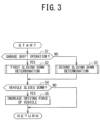
FIG. 3 , a procedure of the vehicle sliding down determination operation to be performed in the control device according to the present embodiment will be explained. Note that this operation is started upon activating theHCU 10, being repeated at a predetermined interval. - At
step S 1, theHCU 10 determines whether the garage shift operation is performed. - If "YES" at step S1 (i.e., when determining that the garage shift operation is performed), the
HCU 10 proceeds to step S2 to perform the first sliding down determination process, otherwise (if "NO" at step S 1) proceeding to step S3 to perform the second sliding down determination process. - Due thereto, the
vehicle 1 is determined whether to slide down in accordance with the second sliding down determination process when thevehicle 1 is driven on the uphill road with the forward range selected, but is determined whether to slide down in accordance with the first sliding down determination process when thevehicle 1 is parked with the garage shift operation, for example. - The first sliding down determination process is performed, after the garage shift operation is detected (e.g., the shift position is changed from the forward/reverse range to the reverse/forward range), until a predetermined period of time (e.g., 2 sec) elapses or until a traveling direction corresponding to the changed range (the reverse/forward range) is detected.
- The
HCU 10 determines, in the respective first and second sliding down determination processes (at steps S2, S3), whether thevehicle 1 slides down using different methods. Note that procedure of these processes will be explained in detail referring toFIGS. 4 and5 orFIGS. 6 and7 . - After step S2 or S3, the
HCU 10 determines, at step S4, whether thevehicle 1 slides down. At step S4, theHCU 10 determines whether the vehicle sliding down, by referring to the result of the first or second sliding down determination process (at step S2, S3). In other words, step S4 inFIG. 3 corresponds to step S16, S19 inFIG. 4 , for example. - If "NO" at step S4 (when determining that the
vehicle 1 does not slide down), theHCU 10 terminates this operation. - If "YES" at step S4 (when determining that the
vehicle 1 slides down), theHCU 10 proceeds to step S5 to increase driving force of thevehicle 1. - Next, referring to
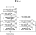
FIGS. 4 and5 , procedure of the respective first and second sliding down determination processes will be explained, which are performed during vehicle travel in the HEV mode using motor torque or in the EV mode. - Firstly, referring to
FIG. 4 , the first sliding down determination process of step S2 inFIG. 3 will be explained in detail, which is performed upon the garage shift operation. - At
step S 11, theHCU 10 calculates the motor rotation acceleration. Subsequently, at step S12, theHCU 10 determines whether the absolute value of the calculated motor rotation acceleration is smaller than a predetermined threshold α. - If "NO" at step S12 (when determining that the absolute value is not smaller than the threshold α), the
HCU 10 terminates this process. - If "YES" at step S12 (when determining that the absolute value is smaller than the threshold α), the
HCU 10 proceeds to step S13 to determine whether the shift position is changed from the reverse range to the forward range by the garage shift operation. - If "YES" at S 13 (when the reverse range is changed into the forward range), the
HCU 10 proceeds to step S14 to determine whether the motor rotation speed is smaller than zero. In other words, at step S14, theHCU 10 determines a traveling direction (forward or backward) of thevehicle 1 using the sign (positive or negative) of the value of the motor rotation speed. For example, if the motor rotation speed has negative value, thevehicle 1 is to backwardly travel. - If "NO" at step S 14 (when determining that the motor rotation speed is not smaller than zero), the
HCU 10 terminates this process. On the other hand, if "YES" at step S 14 (when determining that the motor rotation speed is smaller than zero), theHCU 10 proceeds to step S15 to determine whether the motor rotation acceleration is smaller than zero. In other words, at step S15, theHCU 10 determines a speed increasing direction (forward or backward) of thevehicle 1 using the sign (positive or negative) of the value of the motor rotation acceleration. For example, if the motor rotation acceleration has negative value, thevehicle 1 is to backwardly increase speed thereof. - If "NO" at step S15 (when determining that the motor rotation acceleration is not smaller than zero), the
HCU 10 terminates this process. - If "YES" at step S15 (when determining that the motor rotation acceleration is smaller than zero), the
HCU 10 proceeds to step S16 to determine that thevehicle 1 slides down. After step S16, theHCU 10 terminates this process. - In contrast, if "NO" at step S13 (when determining that the shift position is not changed from the reverse range to the forward range (i.e., the forward range is changed into the reverse range by the garage shift operation), the
HCU 10 proceeds to step S17 to determine whether the motor rotation speed is larger than zero. In other words, at step S17, similar to step S14, theHCU 10 determines a traveling direction (forward or backward) of thevehicle 1 using the sign (positive or negative) of the value of the motor rotation speed. For example, if the motor rotation speed has positive value, thevehicle 1 is to forwardly travel. - If "NO" at step S17 (when determining that the motor rotation speed is not larger than zero), the
HCU 10 terminates this process. - If "YES" at step S17 (when determining that the motor rotation speed is larger than zero), the
HCU 10 proceeds to step S18 to determine whether the motor rotation acceleration is larger than zero. In other words, at step S18, similar to step S15, theHCU 10 determines a speed increasing direction (forward or backward) of thevehicle 1 using the sign (positive or negative) of the value of the motor rotation acceleration. For example, if the motor rotation acceleration has positive value, thevehicle 1 is to forwardly increase speed thereof. - If "NO" at step S18 (when determining that the motor rotation acceleration is not larger than zero), the
HCU 10 terminates this process. If "YES" at step S 18 (when determining that the motor rotation acceleration is larger than zero), theHCU 10 proceeds to step S19 to determine that thevehicle 1 slides down. After step S19, theHCU 10 terminates this process. - Secondly, referring to
FIG. 5 , the second sliding down determination process of step S3 inFIG. 3 will be explained in detail, which is performed unless the garage shift operation is detected. - At step S21, the
HCU 10 determines whether the shift position is in the forward range (i.e., the forward range is selected). - If "YES" at step S21 (when determining that the shift position is in the forward range), the
HCU 10 proceeds to step S22 to determine whether the motor rotation speed is smaller than zero. In other words, at step S22, theHCU 10 determines a traveling direction (forward or backward) of thevehicle 1 using the sign (positive or negative) of the value of the motor rotation speed. For example, if the motor rotation speed has negative value, thevehicle 1 is to backwardly travel. - If "NO" at step S22 (when determining that the motor rotation speed is not smaller than zero), the
HCU 10 terminates this process. If "YES" thereat (when determining that the motor rotation speed is smaller than zero), theHCU 10 proceeds to step S23 to determine that thevehicle 1 slides down. After step S23, theHCU 10 terminates this process. - If "NO" at step S21 (when determining that the shift position is in not the forward range but the reverse range), the
HCU 10 proceeds to step S24 to determine whether the motor rotation speed is larger than zero. In other words, at step S24, theHCU 10 determines a traveling direction (forward or backward) of thevehicle 1 using the sign (positive or negative) of the value of the motor rotation speed. For example, if the motor rotation speed has positive value, thevehicle 1 is to forwardly travel. - If "NO" at step S24 (when determining that the motor rotation speed is not larger than zero), the
HCU 10 terminates this process. If "YES" thereat (when determining that the motor rotation speed is larger than zero), theHCU 10 proceeds to step S25 to determines that thevehicle 1 slides down. After step S25, theHCU 10 terminates this process. - Next, referring to
FIGS. 6 and7 , procedure of the respective first and second sliding down determination processes will be explained, which are performed during vehicle travel in the HEV mode using engine torque or in the engine mode. - Firstly, referring to
FIG. 6 , the first sliding down determination process of step S2 shown inFIG. 3 will be explained in detail, which is performed upon the garage shift operation. Note that the first sliding down determination process shown inFIG. 6 is to be performed during the traveling mode using the engine (e.g., the HEV mode or the engine mode), which is different from that shown inFIG. 4 in this point. - At step S31, the
HCU 10 calculates the vehicle acceleration. At subsequent step S32, theHCU 10 determines whether the shift position is changed from the reverse range to the forward range by the garage shift operation. - If "YES" at S32 (when the reverse range is changed into the forward range), the
HCU 10 proceeds to step S33 to determine whether the vehicle speed is smaller than zero. In other words, at step S33, theHCU 10 determines a traveling direction (forward or backward) of thevehicle 1 using the sign (positive or negative) of the value of the vehicle speed. For example, if the vehicle speed has negative value, thevehicle 1 is to backwardly travel. - If "NO" at step S33 (when determining that the vehicle speed is not smaller than zero), the
HCU 10 terminates this process. On the other hand, if "YES" thereat (when determining that the vehicle speed is smaller than zero), theHCU 10 proceeds to step S34 to determine whether the vehicle acceleration is smaller than zero. In other words, at step S34, theHCU 10 determines a speed increasing direction (forward or backward) of thevehicle 1 using the sign (positive or negative) of the value of the vehicle acceleration. For example, if the vehicle acceleration has negative value, thevehicle 1 is to backwardly increase speed thereof. - If "NO" thereat (when determining that the vehicle acceleration is not smaller than zero), the
HCU 10 terminates this process. If "YES" thereat (when determining that the vehicle acceleration is smaller than zero), theHCU 10 proceeds to step S35 to determine that thevehicle 1 slides down. After step S35, theHCU 10 terminates this process. - In contrast, if "NO" at step S32 (when determining that the shift position is not changed from the reverse range to the forward range (i.e., the forward range is changed into the reverse range by the garage shift operation), the
HCU 10 proceeds to step S36 to determine whether the vehicle speed is larger than zero. In other words, at step S36, similar to step S33, theHCU 10 determines a traveling direction (forward or backward) of thevehicle 1 using the sign (positive or negative) of the value of the vehicle speed. For example, if the vehicle speed has positive value, thevehicle 1 is to forwardly travel. - If "NO" thereat (when determining that the vehicle speed is not larger than zero), the
HCU 10 terminates this process. - If "YES" thereat (when determining that the vehicle speed is larger than zero), the
HCU 10 proceeds to step S37 to determine whether the vehicle acceleration is larger than zero. In other words, at step S37, similar to step S34, theHCU 10 determines a speed increasing direction (forward or backward) of thevehicle 1 using the sign (positive or negative) of the value of the vehicle acceleration. For example, if the vehicle acceleration has positive value, thevehicle 1 is to forwardly increase speed thereof. - If "NO" thereat (when determining that the vehicle acceleration is not larger than zero), the
HCU 10 terminates this process. If "YES" thereat (when determining that the vehicle acceleration is larger than zero), theHCU 10 proceeds to step S38 to determine that thevehicle 1 slides down. After step S38, theHCU 10 terminates this process. - Secondly, referring to
FIG. 7 , the second sliding down determination process of step S3 inFIG. 3 will be explained in detail, which is performed unless the garage shift operation is detected. - At step S41, the
HCU 10 determines whether the shift position is in the forward range (i.e., the forward range is selected). - If "YES" at step S41 (when determining that the shift position is in the forward range), the
HCU 10 proceeds to step S42 to determine whether the vehicle speed is smaller than zero. In other words, at step S42, theHCU 10 determines a traveling direction (forward or backward) of thevehicle 1 using the sign (positive or negative) of the value of the vehicle speed. For example, if the vehicle speed has negative value, thevehicle 1 is to backwardly travel. - If "NO" thereat (when determining that the vehicle speed is not smaller than zero), the
HCU 10 terminates this process. If "YES" thereat (when determining that the vehicle speed is smaller than zero), theHCU 10 proceeds to step S43 to determine that thevehicle 1 slides down. After step S43, theHCU 10 terminates this process. - If "NO" at step S41 (when determining that the shift position is in not the forward range but the reverse range), the
HCU 10 proceeds to step S44 to determine whether the vehicle speed is larger than zero. In other words, at step S44, theHCU 10 determines a traveling direction (forward or backward) of thevehicle 1 using the sign (positive or negative) of the value of the vehicle speed. For example, if the vehicle speed has positive value, thevehicle 1 is to forwardly travel. - If "NO" thereat (when determining that the vehicle speed is not larger than zero), the
HCU 10 terminates this process. If "YES" thereat (when determining that the vehicle speed is larger than zero), theHCU 10 proceeds to step S45 to determine that thevehicle 1 slides down. After step S45, theHCU 10 terminates this process. - As mentioned above, in the present embodiment, the
vehicle 1 includes themotor generator 4 and theengine 2 as driving sources to drive the drivingwheels 5. TheHCU 10 determines, during power on of the vehicle 1 (while being activated), whether the garage shift operation is performed by the driver. - If the
HCU 10 determines that the garage shift operation is performed by the driver, it performs the first sliding down determination process to determine whether thevehicle 1 slides down. Otherwise (unless theHCU 10 determines that the garage shift operation is performed by the driver), theHCU 10 performs the second sliding down determination process to determine whether thevehicle 1 slides down, the second sliding down determination process being different from the first one. - Thus, the
vehicle 1 is determined whether to slide down using different methods in response to present/absence of the garage shift operation, preventing thevehicle 1 from being mistakenly determined to slide down with the garage shift operation to thereby accurately determine the vehicle sliding down. - As the result of the first or second sliding down determination process, when determining that the
vehicle 1 slides down, theHCU 10 increases driving force of thevehicle 1, thereby preventing thevehicle 1 from sliding down. - In the first sliding down determination process, the
vehicle 1 is determined whether to slide down, based on the shift position and the motor rotation speed and acceleration. - Such a sliding down determination process is performed when the garage shift operation is performed, preventing the
vehicle 1 from being mistakenly determined to slide down even if an actual traveling direction (forward or backward) is not reversed upon the garage shift operation (i.e., even if the selected shift position is changed, during vehicle travel at the very slow speed, into another corresponding to a direction opposite to the traveling direction in said vehicle travel). As a result, it is possible to accurately determine the vehicle sliding down. - Specifically, when e.g., the shift position is changed from the reverse range to the forward range by the garage shift operation during backward travel at the very slow speed, such a backward travel may be temporally continued upon the shift position change, but the traveling direction may be reversed from backward to forward after a period of time elapses from the shift position change. In such a case, if the
vehicle 1 is determined, similar to that without the garage shift operation, whether to slide down based on the shift position and the motor rotation speed, immediately after the garage shift operation, the shift position is in the forward range but the motor rotation speed has negative value which corresponds to backward direction, causing the shift position and the traveling direction to mismatch each other to thereby mistakenly determine that thevehicle 1 slides down. - With respect to above, in the present embodiment, when the garage shift operation is performed, the
vehicle 1 is determined whether to slide down based on the shift position and the motor rotation speed and acceleration. Due thereto, even when the shift position is in the forward range but the motor rotation speed has negative value which corresponds to backward direction, thevehicle 1 can be considered, if the motor rotation acceleration has positive value, as being decelerated to be in middle of transition from backward to forward, correctly determining that thevehicle 1 does not slide down. On the other hand, in this case, if the motor rotation acceleration has negative value, the vehicle speed in backward direction increases, correctly determining that thevehicle 1 slides down. - Similarly, when the shift position is changed from the forward range to the reverse range by the garage shift operation during backward travel at the very slow speed, such a forward travel may be temporally continued upon the shift position change, but the traveling direction may be reversed from forward to backward after a period of time elapses from the shift position change. In such a case, if the
vehicle 1 is determined, similar to that without the garage shift operation, whether to slide down based on the shift position and the motor rotation speed, immediately after the garage shift operation, the shift position is in the reverse range but the motor rotation speed has positive value which corresponds to forward direction, causing the shift position and the traveling direction to mismatch each other to thereby mistakenly determine that thevehicle 1 slides down. - Hence, also in this case, the
vehicle 1 is determined whether to slide down based on the shift position and the motor rotation speed and acceleration. Due thereto, even when the shift position is in the reverse range but the motor rotation speed has positive value which corresponds to forward direction, thevehicle 1 can be considered, if the motor rotation acceleration has negative value, as being decelerated to be in middle of transition from forward to backward, correctly determining that thevehicle 1 does not slide down. On the other hand, in this case, if the motor rotation acceleration has positive value, the vehicle speed in forward direction increases, correctly determining that thevehicle 1 slides down. - Thus, it is possible to prevent the
vehicle 1 from being determined to slide down even without an actual vehicle sliding down, thereby avoiding driving force from being unnecessarily increased. - In contrast, in the second sliding down determination process, the
vehicle 1 is determined whether to slide down based on the shift position and the motor rotation speed. - Due thereto, while the garage shift operation is not performed, the
vehicle 1 is determined whether to slide down based on the shift position and the motor rotation speed, shortening a period of time for the vehicle sliding down determination, compared with a case where, as the garage shift operation is performed, thevehicle 1 is determined whether to slide down based on the shift position and the motor rotation speed and acceleration. - Furthermore, the motor rotation acceleration is obtained by differentiating the motor rotation speed, which is of differential value. Driving force generated from the
motor generator 4 is transmitted to thedriving wheels 5 via gears of power transmission mechanism and thus, rotation change or vehicle vibration due to backlash reduction of gears may cause the motor rotation acceleration to rapidly change. For this reason, even when the garage shift operation is not performed, if thevehicle 1 is determined whether to slide down based on, similar to the first sliding down determination, the shift position and the motor rotation speed and acceleration, it may be required to monitor the motor rotation acceleration for a certain period of time to eliminate influence from backlash reduction of gears, lengthening a period of time for the vehicle sliding down determination. With respect thereto, in the present embodiment, unless the garage shift operation is performed, thevehicle 1 is determined whether to slide down based on the shift position and the motor rotation speed without the motor rotation acceleration, shortening the period of time for the vehicle sliding down determination. - In the first sliding down determination process, the absolute value of the motor rotation acceleration is determined whether to be smaller than the predetermined threshold to determine whether the
vehicle 1 slides down based on the shift position and the motor rotation speed and acceleration. - Thereby, it is possible to prevent the
vehicle 1 from being determined to slide down even without an actual sliding down. Specifically, the motor rotation speed to be detected using the resolver is highly accurate. For this reason, the detection value of the motor rotation speed may rapidly change due to backlash reduction of gears. Such a rapid change due thereto is not associated with the above-mentioned vehicle sliding down. Hence, when the absolute value of the motor rotation acceleration is determined to be the predetermined threshold or larger, it is to be omitted from the vehicle sliding down determination (i.e., the sliding down determination is allowed to proceed after the absolute value falls below the predetermined threshold) to thereby prevent an erroneous determination of the sliding down. - In such a first sliding down determination process, the
vehicle 1 may be determined whether to slide down based on the shift position and the vehicle speed and acceleration. - Also in this case, similar to the sliding down determination using the shift position and the motor rotation speed and acceleration, it is possible to accurately determine whether the
vehicle 1 slides down even at the garage shift operation. - Similarly, in the second sliding down determination process, the
vehicle 1 may be determined whether to slide down based on the shift position and the vehicle speed. - Thereby, also in this case, while the garage shift operation is not performed, it is possible to shorten the period of time for the sliding down determination, compared with that for the sliding down determination based on, as the garage shift operation is performed, the shift position and the vehicle speed and acceleration.
- When the
vehicle 1 is determined to slide down in accordance with the first or second sliding down determination process, it is preferable that theengine 2 is driven to thereby increase driving force of thevehicle 1. - Thereby, it is possible to increase driving force of the
vehicle 1 with engine torque even unless themotor generator 4 is allowed to increase driving force of thevehicle 1. - Note that the
motor generator 4 has a characteristic that heating amount becomes large in the vicinity of zero rpm of the motor rotation speed. Thus, themotor generator 4 may not be allowed, at e.g., vehicle start, to increase driving force of thevehicle 1 due to high-temperature of the motor generator. Additionally, themotor generator 4 may not be allowed to increase driving force of thevehicle 1 due to drop of SOC of thesecond battery 33 to supply themotor generator 4 with electric power. Even in such a case, theengine 2 is driven to thereby increase driving force of thevehicle 1 with engine torque. - The
vehicle 1 may be conventional one with theengine 2 as the driving source to drive the drivingwheels 5, without themotor generator 4. Also in such a vehicle, theHCU 10 determines whether the garage shift operation is performed by the driver. If theHCU 10 determines that the garage shift operation is performed by the driver, it performs the first sliding down determination process to determine whether thevehicle 1 slides down. Otherwise (unless theHCU 10 determines that the garage shift operation is performed by the driver), theHCU 10 performs the second sliding down determination process to determine whether thevehicle 1 slides down, the second sliding down determination process being different from the first one. TheHCU 10 increases driving force of thevehicle 1 upon determining that thevehicle 1 slides down in accordance with the first or second sliding down determination process. - Thus, the
vehicle 1 is determined whether to slide down using different methods in response to present/absence of the garage shift operation, preventing thevehicle 1 from being mistakenly determined to slide down with the garage shift operation to thereby accurately determine the vehicle sliding down. - Additionally, as the result of the first or second sliding down determination process, when determining that the
vehicle 1 slides down, theHCU 10 increases driving force of thevehicle 1, thereby preventing thevehicle 1 from sliding down. - In such a conventional vehicle, the first sliding down determination process uses the shift position and the vehicle speed and acceleration.
- Thus, the
vehicle 1 is determined whether to slide down based on the shift position and the vehicle speed and acceleration, accurately determining the vehicle sliding down even with the garage shift operation. - Additionally, in such a conventional vehicle, the second sliding down determination process uses the shift position and the vehicle speed.
- Thus, while the garage shift operation is not performed, the vehicle is determined whether to slide down based on the shift position and the vehicle speed, shortening the period of time for the vehicle sliding down determination, compared with a case where, as the garage shift operation is performed, the
vehicle 1 is determined whether to slide down based on the shift position and the vehicle speed and acceleration. - Although the embodiment of the present invention has been disclosed, it is obvious that those skilled in the art can make changes without departing from the scope of the present invention. It is intended that all such modifications and equivalents are encompassed by the claims.
-
- 1: vehicle
- 2: engine (internal combustion engine)
- 4: motor generator (motor)
- 5: driving wheel
- 10: HCU (garage shift operation determination unit, sliding down determination unit, control unit)
Claims (8)
- A control device of a vehicle (1) with at least one of a motor (4) and an internal combustion engine (2) as driving sources for a driving wheel (5),
the control device comprising:a garage shift operation determination unit (10) to determine whether a garage shift operation of changing a shift position from one of forward and reverse ranges to the other is performed by a driver;a sliding down determination unit (10) to perform, if the garage shift operation determination unit determines that the garage shift operation is performed, a first sliding down determination process of determining whether the vehicle slides down, otherwise performing a second sliding down determination process of determining whether the vehicle slides down, the second sliding down determination process being different from the first sliding down determination process; anda control unit (10) to increase driving force of the vehicle upon the determination that the vehicle slides down. - The control device as claimed in claim 1, whereinthe vehicle includes the motor, andin the first sliding down determination process, the sliding down determination unit determines whether the vehicle slides down, based on: the shift position, and rotation speed and acceleration of the motor; or the shift position, and speed and acceleration of the vehicle.
- The control device as claimed in claim 2, wherein
in the second sliding down determination process, the sliding down determination unit determines whether the vehicle slides down based on the shift position and the rotation speed of the motor. - The control device as claimed in claim 2, wherein
in the first sliding down determination process, the sliding down determination unit: determines whether an absolute value of the rotation acceleration of the motor is smaller than a predetermined threshold; and determines whether the vehicle slides down based on the shift position and the rotation speed and acceleration of the motor, following the determination of the absolute value. - The control device as claimed in claim 1, wherein
in the first sliding down determination process, the sliding down determination unit determines whether the vehicle slides down based on the shift position, and speed and acceleration of the vehicle. - The control device as claimed in claim 5, wherein
in the second sliding down determination process, the sliding down determination unit determines whether the vehicle slides down based on the shift position and the speed of the vehicle. - The control device as claimed in claim 5 or 6, wherein
the vehicle includes the internal combustion engine. - The control device as claimed in any one of claims 1 to 4, whereinthe vehicle includes both of the motor and the internal combustion engine,the control unit drives the internal combustion engine to thereby increase driving force of the vehicle, upon the determination that the vehicle slides down.
Applications Claiming Priority (1)
| Application Number | Priority Date | Filing Date | Title |
|---|---|---|---|
| JP2022035072A JP7753931B2 (en) | 2022-03-08 | 2022-03-08 | Vehicle control device |
Publications (2)
| Publication Number | Publication Date |
|---|---|
| EP4242496A1 true EP4242496A1 (en) | 2023-09-13 |
| EP4242496B1 EP4242496B1 (en) | 2024-12-18 |
Family
ID=85239112
Family Applications (1)
| Application Number | Title | Priority Date | Filing Date |
|---|---|---|---|
| EP23156654.8A Active EP4242496B1 (en) | 2022-03-08 | 2023-02-14 | Control device of vehicle |
Country Status (2)
| Country | Link |
|---|---|
| EP (1) | EP4242496B1 (en) |
| JP (1) | JP7753931B2 (en) |
Families Citing this family (3)
| Publication number | Priority date | Publication date | Assignee | Title |
|---|---|---|---|---|
| JP2019118625A (en) * | 2017-12-29 | 2019-07-22 | 株式会社三洋物産 | Game machine |
| JP2019118620A (en) * | 2017-12-29 | 2019-07-22 | 株式会社三洋物産 | Game machine |
| JP7196395B2 (en) * | 2018-01-31 | 2022-12-27 | 株式会社三洋物産 | game machine |
Citations (2)
| Publication number | Priority date | Publication date | Assignee | Title |
|---|---|---|---|---|
| WO2014193886A1 (en) * | 2013-05-29 | 2014-12-04 | Chrysler Group Llc | Interactive transmission shift techniques |
| JP2021084453A (en) | 2019-11-25 | 2021-06-03 | トヨタ自動車株式会社 | Hybrid vehicle |
Family Cites Families (6)
| Publication number | Priority date | Publication date | Assignee | Title |
|---|---|---|---|---|
| JP4133349B2 (en) | 2003-01-07 | 2008-08-13 | 株式会社豊田自動織機 | Vehicle travel control device |
| JP4106562B2 (en) | 2004-03-09 | 2008-06-25 | 三菱自動車工業株式会社 | Electric vehicle drive control device |
| JP2013183504A (en) | 2012-02-29 | 2013-09-12 | Daihatsu Motor Co Ltd | Play elimination control device of electric vehicle |
| JP2015044495A (en) | 2013-08-28 | 2015-03-12 | トヨタ自動車株式会社 | Hybrid-vehicular control apparatus |
| JP6080835B2 (en) | 2014-12-05 | 2017-02-15 | 本田技研工業株式会社 | Vehicle control device |
| US11136011B2 (en) | 2018-10-16 | 2021-10-05 | Ford Global Technologies, Llc | Method and system for vehicle control |
-
2022
- 2022-03-08 JP JP2022035072A patent/JP7753931B2/en active Active
-
2023
- 2023-02-14 EP EP23156654.8A patent/EP4242496B1/en active Active
Patent Citations (2)
| Publication number | Priority date | Publication date | Assignee | Title |
|---|---|---|---|---|
| WO2014193886A1 (en) * | 2013-05-29 | 2014-12-04 | Chrysler Group Llc | Interactive transmission shift techniques |
| JP2021084453A (en) | 2019-11-25 | 2021-06-03 | トヨタ自動車株式会社 | Hybrid vehicle |
Also Published As
| Publication number | Publication date |
|---|---|
| EP4242496B1 (en) | 2024-12-18 |
| JP2023130656A (en) | 2023-09-21 |
| JP7753931B2 (en) | 2025-10-15 |
Similar Documents
| Publication | Publication Date | Title |
|---|---|---|
| EP4242496B1 (en) | Control device of vehicle | |
| KR20160084036A (en) | Method for learning kisspoint of engine clutch in hybrid vehicle | |
| US12320860B2 (en) | Deterioration diagnosis apparatus of assembled battery and deterioration diagnosis method of assembled battery | |
| EP3147147B1 (en) | Hybrid car in p0-configuration with an electrical machine at a side of a combustion engine that faces away from a clutch in p1-configuration with the electrical machine between the clutch and the combustion engine | |
| JP2020031489A (en) | Vehicle charging lid opening/closing device | |
| JP2017094827A (en) | Hybrid vehicle control device | |
| JP7484562B2 (en) | Hybrid vehicle control device | |
| EP4227133B1 (en) | Control device of hybrid vehicle | |
| US20220290645A1 (en) | Engine start control device | |
| CN108238041B (en) | Hybrid vehicle | |
| JP7120351B2 (en) | hybrid vehicle | |
| EP3988411B1 (en) | Control device of hybrid vehicle | |
| JP7334491B2 (en) | Vehicle drive control device | |
| JP6911348B2 (en) | Hybrid vehicle | |
| CN108725419B (en) | hybrid vehicle | |
| JP2018069947A (en) | Drive control device of hybrid vehicle | |
| US12339326B2 (en) | Deterioration diagnosis apparatus of assembled battery and deterioration diagnosis method of assembled battery | |
| JP2017100472A (en) | Charge control device for hybrid vehicle | |
| CN107989706B (en) | Automatic stop device for engine | |
| EP4124502A1 (en) | Charging system of vehicle | |
| EP4588740A1 (en) | Vehicle start control device | |
| EP3974224B1 (en) | Automatic transmission control device | |
| JP7275896B2 (en) | vehicle engine controller | |
| JP2017114322A (en) | Hybrid vehicle | |
| EP3974226B1 (en) | A hybrid vehicle comprising an automatic transmission control device |
Legal Events
| Date | Code | Title | Description |
|---|---|---|---|
| PUAI | Public reference made under article 153(3) epc to a published international application that has entered the european phase |
Free format text: ORIGINAL CODE: 0009012 |
|
| STAA | Information on the status of an ep patent application or granted ep patent |
Free format text: STATUS: REQUEST FOR EXAMINATION WAS MADE |
|
| 17P | Request for examination filed |
Effective date: 20230214 |
|
| AK | Designated contracting states |
Kind code of ref document: A1 Designated state(s): AL AT BE BG CH CY CZ DE DK EE ES FI FR GB GR HR HU IE IS IT LI LT LU LV MC ME MK MT NL NO PL PT RO RS SE SI SK SM TR |
|
| RIC1 | Information provided on ipc code assigned before grant |
Ipc: F16H 59/70 20060101ALN20240722BHEP Ipc: F16H 59/48 20060101ALN20240722BHEP Ipc: F16H 59/44 20060101ALN20240722BHEP Ipc: F16H 59/36 20060101ALN20240722BHEP Ipc: F16H 61/20 20060101ALN20240722BHEP Ipc: F16H 63/50 20060101AFI20240722BHEP |
|
| GRAP | Despatch of communication of intention to grant a patent |
Free format text: ORIGINAL CODE: EPIDOSNIGR1 |
|
| STAA | Information on the status of an ep patent application or granted ep patent |
Free format text: STATUS: GRANT OF PATENT IS INTENDED |
|
| INTG | Intention to grant announced |
Effective date: 20240911 |
|
| GRAS | Grant fee paid |
Free format text: ORIGINAL CODE: EPIDOSNIGR3 |
|
| GRAA | (expected) grant |
Free format text: ORIGINAL CODE: 0009210 |
|
| STAA | Information on the status of an ep patent application or granted ep patent |
Free format text: STATUS: THE PATENT HAS BEEN GRANTED |
|
| AK | Designated contracting states |
Kind code of ref document: B1 Designated state(s): AL AT BE BG CH CY CZ DE DK EE ES FI FR GB GR HR HU IE IS IT LI LT LU LV MC ME MK MT NL NO PL PT RO RS SE SI SK SM TR |
|
| REG | Reference to a national code |
Ref country code: CH Ref legal event code: EP |
|
| REG | Reference to a national code |
Ref country code: DE Ref legal event code: R096 Ref document number: 602023001358 Country of ref document: DE |
|
| REG | Reference to a national code |
Ref country code: IE Ref legal event code: FG4D |
|
| REG | Reference to a national code |
Ref country code: LT Ref legal event code: MG9D |
|
| PG25 | Lapsed in a contracting state [announced via postgrant information from national office to epo] |
Ref country code: HR Free format text: LAPSE BECAUSE OF FAILURE TO SUBMIT A TRANSLATION OF THE DESCRIPTION OR TO PAY THE FEE WITHIN THE PRESCRIBED TIME-LIMIT Effective date: 20241218 |
|
| PG25 | Lapsed in a contracting state [announced via postgrant information from national office to epo] |
Ref country code: FI Free format text: LAPSE BECAUSE OF FAILURE TO SUBMIT A TRANSLATION OF THE DESCRIPTION OR TO PAY THE FEE WITHIN THE PRESCRIBED TIME-LIMIT Effective date: 20241218 |
|
| PG25 | Lapsed in a contracting state [announced via postgrant information from national office to epo] |
Ref country code: BG Free format text: LAPSE BECAUSE OF FAILURE TO SUBMIT A TRANSLATION OF THE DESCRIPTION OR TO PAY THE FEE WITHIN THE PRESCRIBED TIME-LIMIT Effective date: 20241218 |
|
| PG25 | Lapsed in a contracting state [announced via postgrant information from national office to epo] |
Ref country code: NO Free format text: LAPSE BECAUSE OF FAILURE TO SUBMIT A TRANSLATION OF THE DESCRIPTION OR TO PAY THE FEE WITHIN THE PRESCRIBED TIME-LIMIT Effective date: 20250318 |
|
| REG | Reference to a national code |
Ref country code: NL Ref legal event code: MP Effective date: 20241218 |
|
| PG25 | Lapsed in a contracting state [announced via postgrant information from national office to epo] |
Ref country code: LV Free format text: LAPSE BECAUSE OF FAILURE TO SUBMIT A TRANSLATION OF THE DESCRIPTION OR TO PAY THE FEE WITHIN THE PRESCRIBED TIME-LIMIT Effective date: 20241218 Ref country code: GR Free format text: LAPSE BECAUSE OF FAILURE TO SUBMIT A TRANSLATION OF THE DESCRIPTION OR TO PAY THE FEE WITHIN THE PRESCRIBED TIME-LIMIT Effective date: 20250319 |
|
| PG25 | Lapsed in a contracting state [announced via postgrant information from national office to epo] |
Ref country code: RS Free format text: LAPSE BECAUSE OF FAILURE TO SUBMIT A TRANSLATION OF THE DESCRIPTION OR TO PAY THE FEE WITHIN THE PRESCRIBED TIME-LIMIT Effective date: 20250318 |
|
| PG25 | Lapsed in a contracting state [announced via postgrant information from national office to epo] |
Ref country code: NL Free format text: LAPSE BECAUSE OF FAILURE TO SUBMIT A TRANSLATION OF THE DESCRIPTION OR TO PAY THE FEE WITHIN THE PRESCRIBED TIME-LIMIT Effective date: 20241218 |
|
| REG | Reference to a national code |
Ref country code: AT Ref legal event code: MK05 Ref document number: 1752456 Country of ref document: AT Kind code of ref document: T Effective date: 20241218 |
|
| PG25 | Lapsed in a contracting state [announced via postgrant information from national office to epo] |
Ref country code: SM Free format text: LAPSE BECAUSE OF FAILURE TO SUBMIT A TRANSLATION OF THE DESCRIPTION OR TO PAY THE FEE WITHIN THE PRESCRIBED TIME-LIMIT Effective date: 20241218 |
|
| PG25 | Lapsed in a contracting state [announced via postgrant information from national office to epo] |
Ref country code: PL Free format text: LAPSE BECAUSE OF FAILURE TO SUBMIT A TRANSLATION OF THE DESCRIPTION OR TO PAY THE FEE WITHIN THE PRESCRIBED TIME-LIMIT Effective date: 20241218 |
|
| PG25 | Lapsed in a contracting state [announced via postgrant information from national office to epo] |
Ref country code: ES Free format text: LAPSE BECAUSE OF FAILURE TO SUBMIT A TRANSLATION OF THE DESCRIPTION OR TO PAY THE FEE WITHIN THE PRESCRIBED TIME-LIMIT Effective date: 20241218 |
|
| PG25 | Lapsed in a contracting state [announced via postgrant information from national office to epo] |
Ref country code: IS Free format text: LAPSE BECAUSE OF FAILURE TO SUBMIT A TRANSLATION OF THE DESCRIPTION OR TO PAY THE FEE WITHIN THE PRESCRIBED TIME-LIMIT Effective date: 20250418 |
|
| PG25 | Lapsed in a contracting state [announced via postgrant information from national office to epo] |
Ref country code: PT Free format text: LAPSE BECAUSE OF FAILURE TO SUBMIT A TRANSLATION OF THE DESCRIPTION OR TO PAY THE FEE WITHIN THE PRESCRIBED TIME-LIMIT Effective date: 20250421 |
|
| PG25 | Lapsed in a contracting state [announced via postgrant information from national office to epo] |
Ref country code: EE Free format text: LAPSE BECAUSE OF FAILURE TO SUBMIT A TRANSLATION OF THE DESCRIPTION OR TO PAY THE FEE WITHIN THE PRESCRIBED TIME-LIMIT Effective date: 20241218 |
|
| PG25 | Lapsed in a contracting state [announced via postgrant information from national office to epo] |
Ref country code: RO Free format text: LAPSE BECAUSE OF FAILURE TO SUBMIT A TRANSLATION OF THE DESCRIPTION OR TO PAY THE FEE WITHIN THE PRESCRIBED TIME-LIMIT Effective date: 20241218 Ref country code: AT Free format text: LAPSE BECAUSE OF FAILURE TO SUBMIT A TRANSLATION OF THE DESCRIPTION OR TO PAY THE FEE WITHIN THE PRESCRIBED TIME-LIMIT Effective date: 20241218 |
|
| PG25 | Lapsed in a contracting state [announced via postgrant information from national office to epo] |
Ref country code: SK Free format text: LAPSE BECAUSE OF FAILURE TO SUBMIT A TRANSLATION OF THE DESCRIPTION OR TO PAY THE FEE WITHIN THE PRESCRIBED TIME-LIMIT Effective date: 20241218 |
|
| PG25 | Lapsed in a contracting state [announced via postgrant information from national office to epo] |
Ref country code: CZ Free format text: LAPSE BECAUSE OF FAILURE TO SUBMIT A TRANSLATION OF THE DESCRIPTION OR TO PAY THE FEE WITHIN THE PRESCRIBED TIME-LIMIT Effective date: 20241218 |
|
| PG25 | Lapsed in a contracting state [announced via postgrant information from national office to epo] |
Ref country code: IT Free format text: LAPSE BECAUSE OF FAILURE TO SUBMIT A TRANSLATION OF THE DESCRIPTION OR TO PAY THE FEE WITHIN THE PRESCRIBED TIME-LIMIT Effective date: 20241218 |
|
| PG25 | Lapsed in a contracting state [announced via postgrant information from national office to epo] |
Ref country code: SE Free format text: LAPSE BECAUSE OF FAILURE TO SUBMIT A TRANSLATION OF THE DESCRIPTION OR TO PAY THE FEE WITHIN THE PRESCRIBED TIME-LIMIT Effective date: 20241218 |
|
| PG25 | Lapsed in a contracting state [announced via postgrant information from national office to epo] |
Ref country code: MC Free format text: LAPSE BECAUSE OF FAILURE TO SUBMIT A TRANSLATION OF THE DESCRIPTION OR TO PAY THE FEE WITHIN THE PRESCRIBED TIME-LIMIT Effective date: 20241218 |
|
| REG | Reference to a national code |
Ref country code: DE Ref legal event code: R097 Ref document number: 602023001358 Country of ref document: DE |
|
| PG25 | Lapsed in a contracting state [announced via postgrant information from national office to epo] |
Ref country code: DK Free format text: LAPSE BECAUSE OF FAILURE TO SUBMIT A TRANSLATION OF THE DESCRIPTION OR TO PAY THE FEE WITHIN THE PRESCRIBED TIME-LIMIT Effective date: 20241218 |
|
| PG25 | Lapsed in a contracting state [announced via postgrant information from national office to epo] |
Ref country code: LU Free format text: LAPSE BECAUSE OF NON-PAYMENT OF DUE FEES Effective date: 20250214 |
|
| PLBE | No opposition filed within time limit |
Free format text: ORIGINAL CODE: 0009261 |
|
| STAA | Information on the status of an ep patent application or granted ep patent |
Free format text: STATUS: NO OPPOSITION FILED WITHIN TIME LIMIT |
|
| 26N | No opposition filed |
Effective date: 20250919 |
|
| REG | Reference to a national code |
Ref country code: BE Ref legal event code: MM Effective date: 20250228 |
|
| PGFP | Annual fee paid to national office [announced via postgrant information from national office to epo] |
Ref country code: FR Payment date: 20251231 Year of fee payment: 4 |
|
| PG25 | Lapsed in a contracting state [announced via postgrant information from national office to epo] |
Ref country code: BE Free format text: LAPSE BECAUSE OF NON-PAYMENT OF DUE FEES Effective date: 20250228 |
|
| PG25 | Lapsed in a contracting state [announced via postgrant information from national office to epo] |
Ref country code: IE Free format text: LAPSE BECAUSE OF NON-PAYMENT OF DUE FEES Effective date: 20250214 |
|
| PGFP | Annual fee paid to national office [announced via postgrant information from national office to epo] |
Ref country code: DE Payment date: 20251230 Year of fee payment: 4 |