EP4127623B1 - Fabry-perot interferometer having supporting elements - Google Patents
Fabry-perot interferometer having supporting elements Download PDFInfo
- Publication number
- EP4127623B1 EP4127623B1 EP21718634.5A EP21718634A EP4127623B1 EP 4127623 B1 EP4127623 B1 EP 4127623B1 EP 21718634 A EP21718634 A EP 21718634A EP 4127623 B1 EP4127623 B1 EP 4127623B1
- Authority
- EP
- European Patent Office
- Prior art keywords
- mirror
- mirror plate
- interferometer
- plate
- bonding region
- Prior art date
- Legal status (The legal status is an assumption and is not a legal conclusion. Google has not performed a legal analysis and makes no representation as to the accuracy of the status listed.)
- Active
Links
Images


Classifications
-
- G—PHYSICS
- G01—MEASURING; TESTING
- G01J—MEASUREMENT OF INTENSITY, VELOCITY, SPECTRAL CONTENT, POLARISATION, PHASE OR PULSE CHARACTERISTICS OF INFRARED, VISIBLE OR ULTRAVIOLET LIGHT; COLORIMETRY; RADIATION PYROMETRY
- G01J3/00—Spectrometry; Spectrophotometry; Monochromators; Measuring colours
- G01J3/12—Generating the spectrum; Monochromators
- G01J3/26—Generating the spectrum; Monochromators using multiple reflection, e.g. Fabry-Perot interferometer, variable interference filters
-
- G—PHYSICS
- G01—MEASURING; TESTING
- G01J—MEASUREMENT OF INTENSITY, VELOCITY, SPECTRAL CONTENT, POLARISATION, PHASE OR PULSE CHARACTERISTICS OF INFRARED, VISIBLE OR ULTRAVIOLET LIGHT; COLORIMETRY; RADIATION PYROMETRY
- G01J3/00—Spectrometry; Spectrophotometry; Monochromators; Measuring colours
- G01J3/02—Details
- G01J3/0202—Mechanical elements; Supports for optical elements
-
- G—PHYSICS
- G02—OPTICS
- G02B—OPTICAL ELEMENTS, SYSTEMS OR APPARATUS
- G02B26/00—Optical devices or arrangements for the control of light using movable or deformable optical elements
- G02B26/001—Optical devices or arrangements for the control of light using movable or deformable optical elements based on interference in an adjustable optical cavity
-
- G—PHYSICS
- G02—OPTICS
- G02B—OPTICAL ELEMENTS, SYSTEMS OR APPARATUS
- G02B5/00—Optical elements other than lenses
- G02B5/20—Filters
- G02B5/28—Interference filters
- G02B5/284—Interference filters of etalon type comprising a resonant cavity other than a thin solid film, e.g. gas, air, solid plates
-
- G—PHYSICS
- G02—OPTICS
- G02F—OPTICAL DEVICES OR ARRANGEMENTS FOR THE CONTROL OF LIGHT BY MODIFICATION OF THE OPTICAL PROPERTIES OF THE MEDIA OF THE ELEMENTS INVOLVED THEREIN; NON-LINEAR OPTICS; FREQUENCY-CHANGING OF LIGHT; OPTICAL LOGIC ELEMENTS; OPTICAL ANALOGUE/DIGITAL CONVERTERS
- G02F1/00—Devices or arrangements for the control of the intensity, colour, phase, polarisation or direction of light arriving from an independent light source, e.g. switching, gating or modulating; Non-linear optics
- G02F1/01—Devices or arrangements for the control of the intensity, colour, phase, polarisation or direction of light arriving from an independent light source, e.g. switching, gating or modulating; Non-linear optics for the control of the intensity, phase, polarisation or colour
- G02F1/21—Devices or arrangements for the control of the intensity, colour, phase, polarisation or direction of light arriving from an independent light source, e.g. switching, gating or modulating; Non-linear optics for the control of the intensity, phase, polarisation or colour by interference
-
- G—PHYSICS
- G02—OPTICS
- G02B—OPTICAL ELEMENTS, SYSTEMS OR APPARATUS
- G02B26/00—Optical devices or arrangements for the control of light using movable or deformable optical elements
- G02B26/08—Optical devices or arrangements for the control of light using movable or deformable optical elements for controlling the direction of light
- G02B26/0816—Optical devices or arrangements for the control of light using movable or deformable optical elements for controlling the direction of light by means of one or more reflecting elements
- G02B26/0833—Optical devices or arrangements for the control of light using movable or deformable optical elements for controlling the direction of light by means of one or more reflecting elements the reflecting element being a micromechanical device, e.g. a MEMS mirror, DMD
Definitions
- the present invention relates to optical Fabry-Perot interferometers.
- a Fabry-Perot interferometer comprises a pair of semi-transparent mirrors, which are arranged to operate as an optical cavity.
- a Fabry-Perot interferometer FPI of prior art may comprise a first mirror plate 100 and a second mirror plate 200.
- the first mirror plate 100 has a first semi-transparent mirror M1
- the second mirror plate 200 has a second semi-transparent mirror M2.
- the interferometer may comprise one or more actuators ACU1, ACU2 for changing the distance d F between the mirrors M1, M2.
- the first mirror plate 100 may be bonded to a base plate BASE1 by one or more joints J0.
- the second mirror plate 200 may be bonded to the actuators ACU1, ACU2 by one or more joints J0.
- the actuators may be bonded to the base plate BASE1 by joints J3. Thermal expansion and/or shrinking of the joints J0, J3 may cause deforming forces FX1, FY1, FY2, which may cause significant geometric deformation (DEFORM1) of the mirrors.
- the geometric deformation of the shape of the mirrors may disturb or prevent operation of the Fabry Perot interferometer.
- WO2013/167811 A1 discloses a prior art Fabry-Perot interferometer.
- an interferometer according to claim 1.
- the width or diameter of the mirror plates of the interferometer may be e.g. in the range of 5 mm to 50 mm.
- the semi-transparent mirrors of the interferometer may be produced with a high degree of accuracy.
- the deviations of the semi-transparent mirror from the perfect planar shape may initially be e.g. smaller than 1/200, before the mirror plate is attached to the interferometer.
- the parts of the interferometer may be connected to each other by joints, e.g. by adhesive joints. Thermal expansion of the joints, humidity-induced expansion of the joints, and/or shrinking of the joints may cause that deforming forces are transferred to the mirror plates of the interferometer.
- Adhesive joint may absorb moisture e.g. from ambient air, depending on the relative humidity of the ambient air.
- the second mirror may be substantially parallel with the first mirror during operation.
- the parallelism of the second mirror with respect to the first mirror may be adjusted by using the actuators.
- geometric deformation of the shape of the mirror cannot be typically corrected by using the actuators.
- the mirror plate is supported by supporting elements, wherein the mirror plate is bonded to supporting elements by joints.
- the positions of the bonding regions of the mirror plate may be selected to overlap with a middle plane of the mirror plate, so as to minimize deviations of the shape of the semi-transparent mirror from the initial shape.
- coupling the supporting and deforming forces to the mirror plate via bonding regions located at the middle plane may minimize bending of the mirror of the mirror plate.
- Coupling the supporting and deforming forces to the mirror plate via bonding regions located at the middle plane may ensure that deformations of the upper surface of the mirror plate may substantially compensate deformations of the lower surface of said mirror plate.
- Local deviations of the shape of the semi-transparent mirror from the initial planar shape may preferably be smaller than e.g. ⁇ /500. Local deviations of the shape of the semi-transparent mirror from the initial planar shape may preferably be smaller than e.g. 10 nm. Positioning the joints to overlap with the middle plane of the mirror plate may allow keeping the stress-induced deviations smaller than a predetermined limit, e.g. smaller than 10 nm.
- a spectrometer 700 may comprise a Fabry-Perot interferometer 300.
- An object OBJ1 may reflect, emit and/or transmit light LB1, which may be transmitted through the interferometer 300 in order to monitor the spectrum of the light LB1.
- the interferometer 300 may be used e.g. for measuring reflection, transmission (absorption) and/or emission of the light LB1 of the object OBJ1.
- the Fabry-Perot interferometer 300 comprises a first mirror plate 100 and a second mirror plate 200.
- the first mirror plate 100 comprises a first semi-transparent mirror M1
- the second mirror plate 200 comprises a second semi-transparent mirror M2.
- the mirrors M1, M2 may have e.g. a substantially circular form or a substantially rectangular form.
- the distance d F between the mirrors M1, M2 may be adjusted to provide constructive interference for transmitted light at one or more given wavelengths so that the interferometer 300 may transmit light.
- the distance d F may also be adjusted to provide destructive interference for transmitted light at the given wavelength so that the interferometer 300 may reflect light.
- the mirror distance d F may be adjusted by one or more actuators ACU1, ACU2. Three actuators are arranged to move the second mirror plate 200 with respect to the first mirror plate 100.
- the actuator ACU1, ACU2 may be e.g. a piezoelectric actuator, an electrostatic actuator, an electrostrictive actuator, or a flexoelectric actuator.
- the spectrometer 700 may comprise a control unit CNT1.
- the control unit CNT1 may be arranged to send a control signal SET D to the interferometer 300 in order to adjust the mirror gap d F .
- the interferometer 300 may comprise a driver unit 420.
- the driver unit 420 may e.g. convert a digital control signal SET D into an analog signal suitable for driving one or more actuators.
- the driver unit 420 may provide a signal HV1 for driving an actuator.
- the driver unit 420 may provide e.g. a high voltage signal HV1 for driving a piezoelectric actuator.
- the mirrors M1, M2 may be substantially flat and substantially parallel to each other.
- the flatness of the mirror M1, M2 may be e.g. better than ⁇ N /200, in order to provide a suitable finesse (i.e. the ratio of the free spectral range to the spectral width of a transmission peak).
- ⁇ N denotes a predetermined operating wavelength.
- the predetermined operating wavelength ⁇ N may be e.g. in the range of 500 nm to 4000 nm.
- the predetermined operating wavelength ⁇ N may be e.g. 2000 nm or 4000 nm.
- the interferometer 300 may optionally comprise means for monitoring the distance d F between the mirrors and/or the mirror plates.
- the interferometer 300 may comprise e.g. capacitive means for monitoring the distance.
- the interferometer 300 may comprise e.g. inductive means for monitoring the distance.
- the interferometer 300 may comprise e.g. interferometric means for monitoring the distance.
- the interferometer 300 may optionally comprise capacitive sensor electrodes for capacitively monitoring mirror distance d F .
- Sensor electrodes G1a, G2a may together form a sensor capacitor C1, wherein the capacitance value of the sensor capacitor C1 may depend on the mirror distance d F . Consequently, the mirror distance d F may be monitored by monitoring the capacitance value of the sensor capacitor C1.
- the sensor capacitor C1 may be connected to a capacitance monitoring unit 410 e.g. by conductors CONa, CONb.
- the capacitance monitoring unit 410 may provide a sensor signal S d indicative of the mirror distance d F .
- the sensor capacitor C1 may also be implemented e.g. as shown in Fig. 7a .
- the capacitance monitoring unit 410 may provide a sensor signal S d .
- the sensor signal may be used for monitoring the mirror gap d F .
- the spectral response of the spectrometer 700 may be calibrated e.g. as a function of the mirror gap d F .
- the spectrometer 700 may comprise a memory MEM2 for storing spectral calibration parameters DPAR2.
- the mirror gap d F and/or a spectral position ⁇ may be determined from the sensor signal S d e.g. by using the spectral calibration parameters DPAR2.
- the interferometer 300 may also comprise two or more sensor capacitors for monitoring the parallelism of the mirrors M1, M2, in addition to monitoring the mirror distance d F between the mirrors M1, M2.
- the mirror M2 may be adjusted to be parallel with the mirror M1 e.g. by controlling one or more of the actuators ACU1, ACU2 of the interferometer 300.
- geometric deformation of the shape of the mirror M1 and/or M2 cannot be typically corrected by using the actuators ACU1, ACU2
- the Fabry-Perot interferometer 300 may form transmitted light LB2 by filtering the light LB1 obtained from the object OBJ1.
- the spectrometer 700 may comprise an optical detector DET1.
- the interferometer 300 may be optically coupled to the detector DET1.
- the transmitted light LB2 may impinge on the detector DET1.
- the detector DET1 may be e.g. an image sensor or a non-imaging detector.
- the detector DET1 may provide one or more intensity signals S DET1 indicative of the intensity of the transmitted light LB2.
- the spectrometer 700 may optionally comprise imaging, focusing, or collimating optics 500.
- the optics 500 may be arranged to focus light LB2 to the detector DET1.
- the optics 500 may also be positioned between the interferometer 300 and the sensor DET1.
- the interferometer 300 may also be positioned e.g. within multi-element optics 500.
- the interferometer 300 may be positioned between elements of multi-element optics 500.
- the spectrometer 700 may optionally comprise a memory MEM1 for storing intensity calibration parameters CALPAR1.
- the spectrometer 700 may be arranged to obtain detector signal values S DET1 from the detector DET1, and to determine intensity values X( ⁇ ) from the detector signal values S DET1 by using one or more intensity calibration parameters CALPAR1.
- an intensity value X( ⁇ ) of the light LB1 may be determined from a detector signal S DET1 by using the one or more intensity calibration parameters CALPAR1.
- the spectrometer 700 may optionally comprise a memory MEM3 for storing output OUT1.
- the output OUT1 may comprise e.g. detector signals S DET1 and/or intensity values determined from the detector signals.
- the output OUT1 may e.g. comprise one or more digital images of the object OBJ1, captured by using the interferometer 300 as a spectrally selective filter.
- the spectrometer 700 may comprise a memory MEM4 for storing a computer program PROG1.
- the computer program PROG1 may be configured, when executed by one or more data processors (e.g. CNT1), cause the apparatus 300, 700 perform one or more of the following:
- the spectrometer 700 may optionally comprise a user interface USR1 e.g. for displaying information to a user and/or for receiving commands from the user.
- the user interface USR1 may comprise e.g. a display, a keypad and/or a touch screen.
- the spectrometer 700 may optionally comprise a communication unit RXTX1.
- the communication unit RXTX1 may transmit and/or receive a signal COM1 e.g. in order to receive commands, to receive calibration data, and/or to send output data OUT1.
- the communication unit RXTX1 may have e.g. wired and/or wireless communication capabilities.
- the communication unit RXTX1 may be arranged to communicate e.g. with a local wireless network (Bluetooth, WLAN), with the Internet and/or with a mobile communications network (4G, 5G).
- the spectrometer 700 may optionally comprise one or more optical cut-off filters 510 to limit the spectral response of the detector DET1.
- the light LB2 may propagate substantially in the direction -SZ.
- the optical axis AX1 of the interferometer 300 may be parallel with the direction SZ.
- the light LB2 may propagate substantially in the direction of the optical axis AX1.
- the light LB2 may propagate substantially in the direction -SZ.
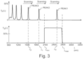
- Fig. 3 shows, by way of example, a spectral transmittance of a Fabry-Perot interferometer 300, and the pass band of an optional filter 510.
- the uppermost curve of Fig. 3 shows the spectral transmittance T F ( ⁇ ) of the Fabry-Perot interferometer 300.
- the spectral transmittance T F ( ⁇ ) may have one or more adjacent transmittance peaks PEAK1, PEAK2, PEAK3 of the Fabry-Perot interferometer 300.
- a first transmittance peak PEAK1 may be at a wavelength ⁇ 0
- a second transmittance peak PEAK2 may be at a wavelength ⁇ 1
- a third transmittance peak PEAK3 may be at a wavelength ⁇ 2 .
- the spectral positions ⁇ 0 , ⁇ 1 , ⁇ 2 of the transmission peaks PEAK1, PEAK2, PEAK3 may depend on the mirror distance d F according to the Fabry-Perot transmission function.
- the spectral positions of the transmission peaks may be changed by changing the mirror gap d F .
- the spectral positions of the transmission peaks may be changed by tuning the mirror gap d F .
- the transmission peaks PEAK1, PEAK2, PEAK3 may also be called passbands of the Fabry-Perot interferometer.
- the spectrometer 700 may optionally comprise one or more optical cut-off filters 510 to limit the spectral response of the spectrometer 700.
- the one or more filters 510 may together provide a spectral transmittance T S ( ⁇ ).
- the one or more filters 510 may provide an optical band pass filter defined by cut-off wavelengths ⁇ min and ⁇ max .
- the Fabry-Perot interferometer 300 comprises a first mirror plate 100, a second mirror plate 200, and one or more actuators ACU1, ACU2 to change the distance d F between the mirrors M1, M2 of the interferometer 300.
- the first mirror plate 100 has a first semi-transmissive mirror M1
- the second mirror plate 200 has a second semi-transmissive mirror M2.
- the M1, M2 may be planar with an accuracy, which is e.g. better than 1/200.
- the width w 100 of the first mirror plate 100 may be e.g. in the range of 5 mm to 50 mm.
- the distance d F between the semi-transparent mirrors M1, M2 may be e.g. in the range of 0.5 ⁇ m to 10 ⁇ m. According to the invention, the distance d F between the semi-transparent mirrors M1, M2 is in the range of 0.2 ⁇ m to 10 ⁇ m.
- the first mirror plate 100 may be stationary, and the second mirror plate 200 may be moved by the actuators ACU1, ACU2, with respect to the first mirror plate 100.
- the Fabry-Perot interferometer 300 comprises three actuators ACU1, ACU2, ACU3 to change the distance d F between the mirrors M1, M2 of the interferometer 300 and/or to adjust the tilt angle between the mirrors M1, M2.
- the first mirror plate 100 and/or the second mirror plate 200 are supported by supporting elements S1.
- the supporting elements S1 may be e.g. bent pieces of metal sheet or blocks.
- the mirror plates 100, 200 are bonded to the supporting elements S1 by joints J1.
- the joints J1 may be positioned close to the middle plane of the mirror plates 100, 200, so as to reduce deformation of the shape of the mirrors M1, M2.
- the semi-transparent mirrors M1, M2 may be e.g. dielectric multilayer coatings deposited on a transparent substrate.
- the substrate material of the mirror plates 100, 200 may be transparent in the operating wavelength range of the interferometer 300.
- the material of the mirror plates 100, 200 may be e.g. glass, silica, silicon or sapphire.
- the supporting elements S1 may e.g. comprise or consist of a metal, glass, silicon (Si), silica (SiO 2 ), sapphire (Al 2 O 3 ) or ceramic material.
- Supporting block elements S1 ( Fig. 4b ) may provide stable support for the mirror plate 100, 200.
- Block elements S1 of Fig. 4b may sometimes transfer horizontal forces (e.g. in direction SX) to the mirror plate 100, 200.
- Using the slightly flexible supporting elements of Fig. 4a may reduce the magnitude of forces transferred to the mirror plate 100, 200, when compared with the supporting blocks of Fig. 4b .
- Flexible supporting elements S1 may e.g. comprise spring steel or Invar alloy (FeNi36).
- the material of the supporting elements S1 for the stationary mirror plate (e.g. M1) may be selected such that the thermal expansion of the supporting elements S1 may at least partly compensate thermal expansion of the joints J2.
- the material of the supporting elements S1 for the movable mirror plate (e.g. M2) may be selected such that the thermal expansion of the supporting elements S1 may at least partly compensate thermal expansion of the joints J2, J3 and thermal expansion of the one or more actuators ACU1.
- the slightly flexible supporting elements of Fig. 4a may provide a less stable support for the mirror plates, when compared with the supporting blocks of Fig. 4b .
- the reduced stability of the flexible elements S1 may be at least partly compensated by monitoring and correcting the position of the mirror plate 200 by using the actuators.
- the position of the mirror plate 200 may be monitored e.g. by using the capacitive sensor electrodes G1a, G2a, G1b, G2b.
- the position of the mirror plate 200 may be corrected by using the actuators ACU1, ACU2.
- the interferometer 300 comprises a base plate BASE1.
- the first mirror plate 100 and the second mirror plate 200 are attached to the base plate BASE1 via the supporting elements S1.
- the first mirror plate 100 is bonded to the supporting elements S1 by joints J1.
- the support elements S1 of the first mirror plate 100 may be attached to the base plate BASE1 by joints J2.
- the support elements S1 of the first mirror plate 100 may be attached e.g. to a mounting surface SRF3 of the base plate BASE1 by the joints J2.
- the surface SRF3 may be e.g. substantially perpendicular to the optical axis AX1 of the interferometer 300.
- the second mirror plate 200 may be bonded to the supporting elements S1 by joints J1.
- the support elements S1 of the second mirror plate 200 may be attached to the actuators ACU1, ACU2 by joints J2.
- the actuators ACU1, ACU2 may be attached to the base plate BASE1 by joints J2.
- the support elements S1 of the second mirror plate 200 may be attached e.g. to the mounting surface SRF3 by the joints J2.
- the joints J1, J2, J3 may be e.g. adhesive joints.
- the joints J1, J2, J3 may comprise e.g. an adhesive (ADH1).
- the joints J1, J2, J3 may also be formed e.g. by welding or soldering.
- the interferometer 300 may be optionally assembled such that a gap GAP3 remains between the first mirror plate 100 and the base plate BASE1.
- the gap GAP3 may reduce the probability of causing deformation of the mirror plate 100.
- the interferometer 300 may optionally comprise capacitive sensor electrodes (G1a, G2a, G1b, G2b) for monitoring the distance d F between the mirrors M1, M2 and/or for monitoring a tilt angle of the mirror M2 with respect to the mirror M1.
- capacitive sensor electrodes G1a, G2a, G1b, G2b
- the first mirror plate 100 may comprise sensor electrodes G1a, G1b.
- the second mirror plate 200 may comprise sensor electrodes G2a, G2b.
- the electrodes G1a and G2a may together form a first sensor capacitor C1, which has a capacitance C 1 .
- the electrodes G1b and G2b may together form a second sensor capacitor C2, which has a capacitance C 2 .
- the sensor capacitors C1, C2 may also be implemented e.g. as shown in Fig. 7a .
- the distance between the electrodes G1a, G2a may depend on the mirror distance d F
- the capacitance C 1 of the first sensor capacitor C1 may depend on the distance between the electrodes G1a, G2a such that the mirror distance d F near the electrodes G1a, G2a may be monitored by monitoring the capacitance C 1 of the first sensor capacitor C1.
- the mirror distance d F close to the electrodes G2a, G2b may be monitored by monitoring the capacitance C 2 of the second sensor capacitor C2, respectively.
- the mirror distance d F and/or tilt angle may also be monitored e.g. by analyzing one or more optical signals transmitted through the interferometer 300.
- the sensor electrodes may also be omitted.
- the base plate BASE1 may optionally comprise an opening OPE1 for light LB1, LB2, which is transmitted through the interferometer 300.
- each supporting element S1 of the first mirror plate 100 is bonded to the first mirror plate 100 by a joint J1.
- the mirror plate 100 is bonded to one or more supporting elements S1 by three or more joints J1.
- the number of the joints J1 of the first mirror plate 100 may be equal to three in order to minimize internal stress of the mirror plate 100.
- the joints J1 may be e.g. adhesive joints.
- Each joint J1 is bonded to the first mirror plate 100 at a bonding region REG1.
- the mirror plate 100 may have a first surface SRF11 and a second surface SRF12.
- the surface SRF11 may be at least partly defined by the outer surface of the first mirror M1.
- the surface SRF11 may be parallel with the first mirror M1.
- the first surface SRF11 and a second surface SRF12 may define the thickness h 100 of the mirror plate 100.
- the second surface SRF12 may be e.g. substantially parallel with the first surface SRF11.
- the second surface SRF12 may also be slightly tilted with respect to the first surface SRF11 in order to reduce an effect of unwanted reflections.
- the first surface SRF11 and the second surface SRF12 may define a non-zero wedge angle.
- the joints J1 of the first mirror plate 100 may be positioned close to the middle plane PLN1 of the first mirror plate 100. Positioning the joints J1 close to the middle plane may reduce or minimize geometric deformation of the mirrors M1, M2 away from the planar shape. A joint J1 may transfer a horizontal deforming force (e.g. in the direction SX) to the mirror plate.
- the distance d 1 between each bonding region REG1 and the first substantially planar surface SRF11 is greater than 30% of the thickness h 100 of the mirror plate 100
- the distance d 2 between each bonding region REG1 and the second substantially planar surface SRF12 is greater than 30% of the thickness h 100 of the mirror plate 100.
- the distance d 1 between each bonding region REG1 and the first substantially planar surface SRF11 is greater than 30% of the thickness h 100 of the mirror plate 100, and the distance d 3 between the lowermost edge of each bonding region REG1 and the first substantially planar surface SRF11 may be e.g. smaller than 70% of the thickness h 100 of the mirror plate 100.
- each bonding region REG1 may overlap the central plane PLN1 of the first mirror plate 100.
- the central plane PLN1 may meet each bonding region REG1 of the first mirror plate 100.
- resulting deformations of the upper surface SRF11 and the lower surface SRF12 may be substantially symmetric with respect to the middle plane PLN1.
- a horizontal deforming force may cause a tendency of the upper surface SRF11 to deflect upwards, but this tendency may be effectively compensated by a corresponding tendency of the lower surface SRF12 to deflect downwards. Consequently, a deformation of the lower surface SRF12 may substantially compensate a deformation of the upper surface SRF11.
- Causing the deforming force to act on the middle plane may minimize geometric deformation of the mirrors M1, M2.
- causing the deforming force to act on the middle plane may minimize bending of the mirrors M1, M2.
- Each bonding region REG1 is substantially perpendicular to the central plane PLN1 of the first mirror plate 100, e.g. in order to further ensure that horizontal forces are transferred symmetrically from the supporting elements S1 to the mirror plate.
- Each bonding region REG1 may be located on a side surface (SRF10) of the mirror plate, the side surface (SRF10) being substantially perpendicular to the central plane PLN1 of the first mirror plate 100.
- a mirror plate 100 with perpendicular side surfaces (SRF10) may be substantially symmetrical with respect to the central plane PLN1, e.g. in order to minimize deformations and/or in order to simplify production of the mirror plate 100.
- a joint J1 may also transfer a deforming torque to the mirror plate.
- the maximum dimension d MAX of the bonding region REG1 may be smaller than a predetermined limit in order to minimize or avoid transferring a deforming torque from the supporting element S1 to the mirror plate 100.
- the maximum dimension d MAX of each bonding region REG1 of the first mirror plate 100 may be e.g. smaller than 30% of the thickness h 100 of the mirror plate 100.
- the bonding region REG1 may have a first dimension w REG1 in a first direction along the central plane PLN1, and the bonding region REG1 may have a second dimension h REG1 in a second direction, which is perpendicular to the first direction.
- the first dimension w REG1 may be e.g. the width of the bonding region REG1
- the second dimension h REG1 may be e.g. the height of the bonding region REG1.
- the height h REG1 of each bonding region REG1 of the first mirror plate 100 may be e.g. smaller than 30% of the thickness h 100 of the mirror plate 100.
- the width w REG1 of each bonding region REG1 of the first mirror plate 100 may also be e.g. smaller than 30% of the thickness h 100 of the mirror plate 100.
- SX, SY, and SZ may denote orthogonal directions.
- the mirror M1 of the first mirror plate 100 may be in a plane defined by the directions SX and SY.
- SZ may denote the "vertical direction”.
- a mirror plate may have an "upper” surface and a “lower” surface with respect to the direction SZ.
- the "upper” surface SRF11 may be above the “lower” surface SRF12 in the direction SZ.
- the “lower” surface SRF12 may be below the "upper” surface SRF11.
- In-coming light LB1 may propagate in the direction -SZ from the surface SRF21 to the surface SRF22.
- the mirror M1 may be below the mirror M2.
- Transmitted light LB2 may propagate in the direction -SZ from the surface SRF11 to the surface SRF12.
- the distances d 1 , d 2 , d 3 may be defined in the direction of the optical axis (SZ).
- the middle plane PLN1 of the first mirror plate 100 is at the halfway between the upper surface SRF11 and the lower surface SRF12.
- the distance d P1 between the middle plane PLN1 and the upper surface SRF11 is equal to the distance d P2 between the middle plane PLN1 and the lower surface SRF12.
- the first surface SRF11 may be substantially parallel with the second surface SRF12.
- the middle plane PLN1 may be substantially parallel with the first surface SRF11.
- the first surface SRF11 and the second surface SRF12 may also define a non-zero wedge angle e.g. in order to reduce unwanted reflections.
- the supporting element S1 may also be e.g. an annular ring, which may be attached to the first mirror plate 100 by three joints J1.
- each bonding region REG1 of the second mirror plate 200 may overlap the central plane PLN2 of the second mirror plate 200.
- the central plane PLN2 may meet each bonding region REG1 of the second mirror plate 200.
- the second mirror plate 200 may have a first substantially planar surface SRF21 and a second substantially planar surface SRF22.
- the surface SRF22 may be at least partly defined by the outer surface of the second mirror M2.
- the surface SRF22 may be parallel with the mirror M2.
- the first substantially planar surface SRF21 and the second substantially planar surface SRF22 may define the maximum thickness h 200 of the second mirror plate 200.
- the middle plane PLN2 of the second mirror plate 200 is at the halfway between the upper surface SRF21 and the lower surface SRF22.
- the first surface SRF21 may be substantially parallel with the second surface SRF22.
- the middle plane PLN2 may be substantially parallel with the surface SRF22.
- the first surface SRF21 and the second surface SRF22 of the plate 200 may also define a non-zero wedge angle e.g. in order to reduce an effect of unwanted reflections.
- the second mirror plate 200 may be bonded to one or more first supporting elements S1 by three or more joints J1. Each joint J1 may be bonded to the second mirror plate 200 at a bonding region REG1.
- the distance d 21 between each bonding region REG1 and the first substantially planar surface SRF21 may be greater than 30% of the thickness h 200 of the second mirror plate, and the distance d 22 between each bonding region REG1 and the second substantially planar surface SRF22 may be greater than 30% of the thickness h 200 of the second mirror plate 200.
- the distance d 22 between each bonding region REG1 and the substantially planar surface SRF22 may be greater than 30% of the thickness h 200 of the second mirror plate 200, and the distance d 23 between the uppermost edge of each bonding region REG1 and the substantially planar surface SRF22 may be smaller than 70% of the thickness h 200 of the second mirror plate 200.
- the distances d 21 , d 22 , d 23 may be defined in the direction of the optical axis (SZ).
- Each bonding region REG1 of the second mirror plate 200 may be substantially perpendicular to the first substantially planar surface SRF21 of the second mirror plate 200.
- the maximum dimension d MAX of each bonding region REG1 of the second mirror plate 200 may be smaller than 30% of the thickness h 200 of the second mirror plate 200.
- the supporting elements S1 may have a first bonding region REG11 and a second bonding region REG12.
- the first bonding region REG11 may be attached to the bonding region REG1 of the mirror plate (100, 200) by a joint J1.
- the second bonding region REG12 may be attached the surface SRF3 of the base plate BASE1 or a bonding surface of an actuator (ACU1) by a joint J2.
- the first bonding region REG11 may be substantially perpendicular to the mirror M1, M2 of the mirror plate.
- the second bonding region REG12 may be substantially parallel with the mirror M1, M2 of the mirror plate.
- An angle ⁇ 1 between the regions REG11, REG12 may be substantially equal to 90 degrees.
- the flexible support element S1 of Fig. 5d may reduce the magnitude of forces transferred to the mirror plate.
- the support element of Fig. 5e may provide more stable support, when compared with the support element of Fig. 5d .
- the mirrors M1, M2 may be rather close to each other.
- the interferometer 300 may be produced such that a target value of the mirror distance d F is e.g. in the range of 0.2 ⁇ m to 10 ⁇ m.
- the risk of mutual contact between the mirrors may be high when the target value is smaller than 0.5 ⁇ m.
- Accidental contact of the mirror M1 with the mirror M2 may cause permanent damage to the interferometer 300.
- the mirrors, the actuators, and/or other structures of the interferometer 300 may be damaged in case of the contact.
- shrinking of the joints J0 of the second plate 200 may pull the second plate 200 towards the first plate 100 so that mirror M1 may come into contact with the mirror M2.
- Each bonding region REG1 is substantially perpendicular to the central plane of the mirror plate.
- the perpendicular orientation of the bonding region REG1 may reduce the risk of damaging the interferometer 300 e.g. in case of shrinking and/or expansion of the joints.
- the interferometer 300 may be produced e.g. such that the joints J1 are formed on the bonding regions REG1 after the joints J2, J3 have been formed, wherein the bonding regions REG1 may have said perpendicular orientation.
- the joints J1 may be adhesive joints, which may be cured after the joints (J2, J3) have been formed.
- the interferometer 300 may be produced such that the joints J2 for the first mirror plate 100 and the joints J2 for the second mirror plate 200 are cured substantially simultaneously at a substantially similar rate, so as to reduce or minimize relative movement of the second mirror plate 200 with respect to the first mirror plate during said curing. Consequently, the risk of damaging the mirrors M1, M2 due to mutual contact may be reduced.
- Fig. 6a shows, by way of example, in a three-dimensional exploded view of a Fabry-Perot interferometer 300.
- the interferometer 300 comprises a first mirror plate 100, a second mirror plate 200, and three actuators ACU1, ACU2, ACU3.
- the first mirror plate 100 may be supported by three joints J1, and the second mirror plate 200 may be supported by three joints J1.
- the first mirror plate 100 is attached to the base plate BASE1 via the joints J1 and via supporting elements S1.
- the second mirror plate 200 is attached to the actuators ACU1, ACU2, ACU3 via the joints J1 and via supporting elements S1.
- Using the three actuators may allow adjusting an average value of the mirror distance d F and adjusting the tilt of the mirror M2 about a first axis (e.g. direction SX) and about a second axis (e.g. direction SY).
- the interferometer 300 may comprise sensor electrodes G1a, G2a, G1b, G2b, G3a, G3c to implement three or more sensor capacitors. Using the three or more sensor capacitors may allow monitoring the average value of the mirror distance d F and monitoring the tilt of the mirror M2 about a first axis and about a second axis.
- the monitoring unit 410 may comprise multiple inputs for the sensor capacitors.
- the sensor electrodes may be arranged to monitor the alignment of the second mirror plate 200 with respect to the first mirror plate 100.
- a non-zero difference between the capacitance of a first sensor capacitor (formed by electrodes G1a, G2a) and the capacitance of a third sensor capacitor (formed by electrodes G1c, G2c) may indicate that the second plate 200 is tilted about the axis SX.
- Figs. 6b, 6c , and 6d show, by way of example, in a top view, different positions of support elements S1 for supporting the mirror plate 200 of the interferometer 300.
- Fig. 6b and 6c show supporting a substantially rectangular mirror plate 200.
- Fig. 6d shows supporting a substantially circular mirror plate 200.
- the interferometer 300 may comprise one or more capacitive sensors C1 for monitoring the mirror distance d F .
- the sensor C1 may comprise a first sensor electrode G1a, a second sensor electrode G2a, and an intermediate sensor electrode G0a.
- the electrodes G1a, G2a may be attached to the first stationary mirror plate 100.
- the intermediate electrode G0a may be attached to the movable second mirror plate 200.
- the first electrode and the intermediate electrode may form a first capacitor C11.
- the intermediate electrode and the second electrode may form a second capacitor C12.
- the capacitive sensor C1 may comprise the capacitors C11 and C12, which may be connected in series via the intermediate electrode G0a.
- the electrodes G1a, G2a of the sensor capacitor C1 may be connected to a capacitance monitoring unit 410 e.g. by conductors CONa, CONb.
- the capacitance monitoring unit 410 may provide a sensor signal S d indicative of the mirror distance d F .
- Fig. 7b shows, by way of example, a relation between the mirror distance d F and the capacitance value C d of a sensor capacitor.
- the curve CCRV1 of Fig. 8 shows the sensor capacitance C d as the function of the mirror gap d F .
- the value of the sensor capacitance C d may be inversely proportional to the value of the electrode distance.
- C d,1 denotes the sensor capacitance at a first mirror distance value d F,1 .
- C d,2 denotes the sensor capacitance at a second mirror distance value d F,2 .
- the control unit CNT1 may be arranged to determine the value of the mirror distance d F from the measured value of the sensor capacitance C d .
- the capacitance monitoring unit 410 may provide a sensor signal value S d,1 when the sensor capacitance has a value C d,1 .
- the capacitance monitoring unit 410 may provide a sensor signal value S d,2 when the sensor capacitance has a value C d,2 .
- Fig. 8 shows, by way of example, the spectral intensity I( ⁇ ) of light LB1 received from an object OBJ1.
- the spectral intensity I( ⁇ ) may have a value X( ⁇ 0 ) at a wavelength ⁇ 0 .
- the value X( ⁇ 0 ) may be determined from the detector signal S DET1 obtained from the optical detector DET1.
- the wavelength ⁇ 0 may be selected by adjusting the mirror gap d F before the detector signal S DET1 is obtained from the optical detector DET1.
- the mirror gap d F may be scanned during a measurement in order to measure spectral range of the spectrum OSPEC1 of the object OBJ1.
- the object OBJ1 may be e.g. a real object or a virtual object.
- a real object OBJ1 may be e.g. in solid, liquid, or gaseous form.
- the real object OBJ1 may be a cuvette filled with a gas.
- the real object OBJ1 may be e.g. a plant (e.g. tree or a flower), a combustion flame, or an oil spill floating on water.
- the real object OBJ1 may be e.g. the sun or a star observed through a layer of absorbing gas.
- the real object may be e.g. an image printed on a paper.
- a virtual object OBJ1 may be e.g. an optical image formed by another optical device.
- the interferometer 300 may be suitable for filtering and/or analyzing infrared light.
- the materials and the dimensions of the mirror plate 100 may be selected such that a Fabry Perot interferometer 300 comprising the mirror plate 100 may be applicable for spectral analysis of infrared light.
- the Fabry-Perot interferometer may be used as an optical filter, which has a variable mirror gap.
- An optical device may comprise one or more Fabry-Perot interferometers.
- the optical device may be e.g. a non-imaging spectrometer, an imaging spectrometer, a chemical analyzer, a biomedical sensor, and/or a component of a telecommunication system.
- the first mirror plate 100 may be e.g. rectangular or circular, when viewed in the direction of the optical axis AX1 (direction -SZ).
- the second mirror plate 200 may be e.g. rectangular or circular, when viewed in the direction of the optical axis AX1.
- the first mirror plate 100 may be smaller than the second mirror plate 200, the first mirror plate 100 may be larger than the second mirror plate 200, or the mirror plates 100, 200 may be of equal size.
- the width or diameter w 100 of the first mirror plate 100 may also be greater than or equal to the width or diameter w 200 of the second mirror plate 200.
- the term "plate” may refer to a body, which has one or more substantially planar portions.
- the plate may have a first substantially planar portion so as to minimize wavefront distortion of light transmitted and/or reflected by said planar portion.
- the plate may optionally have a second substantially planar portion, so as to minimize wavefront distortion of light transmitted through the first substantially planar portion and the second substantially planar portion.
- the first planar portion may cover the entire top surface of the plate, or the first planar portion may cover less than 100% of the top surface of the plate.
- the second planar portion may cover the entire bottom surface of the plate, or the second planar portion may cover less than 100% of the bottom surface of the plate.
- the plate may optionally have e.g. one or more protruding portions and/or recessed portions.
- first planar portion may be substantially parallel to the second planar portion.
- first planar portion and the second planar portion may define a non-zero wedge angle e.g. in order to reduce unwanted reflections.
- the supporting blocks S1 may provide more stable support for the mirror plate M1 and/or M2, when compared with the slightly flexible supporting elements.
- the first supporting elements S1 may be rigid.
- the supporting blocks S1 may be implemented as rigid non-flexible elements S1.
- the interferometer 300 may be produced such that the joints J2 are formed after the joints J1 and J3 have been formed.
- the joints J2 may be adhesive joints, which may be cured after the joints J1 and J3 have been formed.
- the width w 100 of the first mirror plate 100 may be e.g. in the range of 5 mm to 100 mm. In particular, the width w 100 of the first mirror plate 100 may be e.g. in the range of 5 mm to 50 mm.
- the materials and the dimensions of the mirror plate 100 may also be selected such that a Fabry-Perot interferometer 300 comprising the mirror plate 100 may be applicable for spectral analysis of visible light.
- the operating wavelength range of the interferometer may include e.g. the range of 380 nm to 760 nm.
- the materials and the dimensions of the mirror plate 100 may also be selected such that a Fabry-Perot interferometer 300 comprising the mirror plate 100 may be applicable for spectral analysis of ultraviolet light.
- the operating wavelength range of the interferometer may include e.g. the range of 150 nm to 380 nm.
- An operating wavelength ⁇ N of the Fabry-Perot interferometer 300 may be e.g. in the range of 150 nm to 6000 nm.
Landscapes
- Physics & Mathematics (AREA)
- Spectroscopy & Molecular Physics (AREA)
- General Physics & Mathematics (AREA)
- Optics & Photonics (AREA)
- Nonlinear Science (AREA)
- Mechanical Light Control Or Optical Switches (AREA)
Description
- The present invention relates to optical Fabry-Perot interferometers.
- A Fabry-Perot interferometer comprises a pair of semi-transparent mirrors, which are arranged to operate as an optical cavity.
- Referring to
Figs. 1a and 1b , a Fabry-Perot interferometer FPI of prior art may comprise afirst mirror plate 100 and asecond mirror plate 200. Thefirst mirror plate 100 has a first semi-transparent mirror M1, and thesecond mirror plate 200 has a second semi-transparent mirror M2. The interferometer may comprise one or more actuators ACU1, ACU2 for changing the distance dF between the mirrors M1, M2. - The
first mirror plate 100 may be bonded to a base plate BASE1 by one or more joints J0. Thesecond mirror plate 200 may be bonded to the actuators ACU1, ACU2 by one or more joints J0. The actuators may be bonded to the base plate BASE1 by joints J3. Thermal expansion and/or shrinking of the joints J0, J3 may cause deforming forces FX1, FY1, FY2, which may cause significant geometric deformation (DEFORM1) of the mirrors. The geometric deformation of the shape of the mirrors may disturb or prevent operation of the Fabry Perot interferometer. -
WO2013/167811 A1 discloses a prior art Fabry-Perot interferometer. - According to an aspect, there is provided an interferometer according to
claim 1. - Further aspects are defined in the other claims.
- The width or diameter of the mirror plates of the interferometer may be e.g. in the range of 5 mm to 50 mm. The semi-transparent mirrors of the interferometer may be produced with a high degree of accuracy. The deviations of the semi-transparent mirror from the perfect planar shape may initially be e.g. smaller than 1/200, before the mirror plate is attached to the interferometer.
- The parts of the interferometer may be connected to each other by joints, e.g. by adhesive joints. Thermal expansion of the joints, humidity-induced expansion of the joints, and/or shrinking of the joints may cause that deforming forces are transferred to the mirror plates of the interferometer. Adhesive joint may absorb moisture e.g. from ambient air, depending on the relative humidity of the ambient air.
- The second mirror may be substantially parallel with the first mirror during operation. The parallelism of the second mirror with respect to the first mirror may be adjusted by using the actuators. However, geometric deformation of the shape of the mirror cannot be typically corrected by using the actuators.
- The mirror plate is supported by supporting elements, wherein the mirror plate is bonded to supporting elements by joints. The positions of the bonding regions of the mirror plate may be selected to overlap with a middle plane of the mirror plate, so as to minimize deviations of the shape of the semi-transparent mirror from the initial shape. In particular, coupling the supporting and deforming forces to the mirror plate via bonding regions located at the middle plane may minimize bending of the mirror of the mirror plate. Coupling the supporting and deforming forces to the mirror plate via bonding regions located at the middle plane may ensure that deformations of the upper surface of the mirror plate may substantially compensate deformations of the lower surface of said mirror plate.
- Local deviations of the shape of the semi-transparent mirror from the initial planar shape may preferably be smaller than e.g. λ/500. Local deviations of the shape of the semi-transparent mirror from the initial planar shape may preferably be smaller than e.g. 10 nm. Positioning the joints to overlap with the middle plane of the mirror plate may allow keeping the stress-induced deviations smaller than a predetermined limit, e.g. smaller than 10 nm.
- In the following examples, several variations will be described in more detail with reference to the appended drawings, in which
- Fig. 1a
- shows, by way of example, in a cross-sectional side view, a Fabry-Perot interferometer of Prior Art,
- Fig. 1b
- shows, by way of example, in a cross-sectional side view, geometric deformation of the mirrors of the interferometer of
Fig. 1a , - Fig. 2
- shows, by way of example, in a cross-sectional side view, a spectrometer, which comprises a Fabry-Perot interferometer,
- Fig. 3
- shows, by way of example, spectral transmittance peaks of a Fabry-Perot interferometer.
- Fig. 4a
- shows, by way of example, in a cross-sectional side view, a Fabry-Perot interferometer,
- Fig. 4b
- shows, by way of example, in a cross-sectional side view, a Fabry-Perot interferometer,
- Fig. 5a
- shows, by way of example, in a side view, a joint of the mirror plate,
- Fig. 5b
- shows, by way of example, in an end view, the joint of
Fig. 5a , - Fig. 5c
- shows, by way of example, in a side view, a joint of the second mirror plate,
- Fig. 5d
- shows, by way of example, in a side view, a support element for a mirror plate,
- Fig. 5e
- shows, by way of example, in a side view, a support element for a mirror plate,
- Fig. 6a
- shows, by way of example, an exploded three-dimensional view of the Fabry-Perot interferometer,
- Fig. 6b
- shows, by way of example, in a top view, positions of support elements with respect to the second mirror plate,
- Fig. 6c
- shows, by way of example, in a top view, positions of support elements with respect to the second mirror plate,
- Fig. 6d
- shows, by way of example, in a top view, positions of support elements with respect to the second mirror plate,
- Fig. 7a
- shows, by way of example, in a side view, a capacitive sensor for monitoring the distance between the mirrors of the interferometer,
- Fig. 7b
- shows, by way of example, determining a distance between the mirrors by monitoring a capacitor signal, and
- Fig. 8
- shows, by way of example, measuring spectral intensity by using the interferometer.
- Referring to
Fig. 2 , aspectrometer 700 may comprise a Fabry-Perot interferometer 300. An object OBJ1 may reflect, emit and/or transmit light LB1, which may be transmitted through theinterferometer 300 in order to monitor the spectrum of the light LB1. Theinterferometer 300 may be used e.g. for measuring reflection, transmission (absorption) and/or emission of the light LB1 of the object OBJ1. - The Fabry-
Perot interferometer 300 comprises afirst mirror plate 100 and asecond mirror plate 200. Thefirst mirror plate 100 comprises a first semi-transparent mirror M1, and thesecond mirror plate 200 comprises a second semi-transparent mirror M2. The mirrors M1, M2 may have e.g. a substantially circular form or a substantially rectangular form. - The distance dF between the mirrors M1, M2 may be adjusted to provide constructive interference for transmitted light at one or more given wavelengths so that the
interferometer 300 may transmit light. The distance dF may also be adjusted to provide destructive interference for transmitted light at the given wavelength so that theinterferometer 300 may reflect light. - The mirror distance dF may be adjusted by one or more actuators ACU1, ACU2. Three actuators are arranged to move the
second mirror plate 200 with respect to thefirst mirror plate 100. The actuator ACU1, ACU2 may be e.g. a piezoelectric actuator, an electrostatic actuator, an electrostrictive actuator, or a flexoelectric actuator. - The
spectrometer 700 may comprise a control unit CNT1. The control unit CNT1 may be arranged to send a control signal SETD to theinterferometer 300 in order to adjust the mirror gap dF. Theinterferometer 300 may comprise adriver unit 420. Thedriver unit 420 may e.g. convert a digital control signal SETD into an analog signal suitable for driving one or more actuators. Thedriver unit 420 may provide a signal HV1 for driving an actuator. Thedriver unit 420 may provide e.g. a high voltage signal HV1 for driving a piezoelectric actuator. - The mirrors M1, M2 may be substantially flat and substantially parallel to each other. The flatness of the mirror M1, M2 may be e.g. better than λN/200, in order to provide a suitable finesse (i.e. the ratio of the free spectral range to the spectral width of a transmission peak). λN denotes a predetermined operating wavelength. The predetermined operating wavelength λN may be e.g. in the range of 500 nm to 4000 nm. The predetermined operating wavelength λN may be e.g. 2000 nm or 4000 nm.
- The
interferometer 300 may optionally comprise means for monitoring the distance dF between the mirrors and/or the mirror plates. Theinterferometer 300 may comprise e.g. capacitive means for monitoring the distance. Theinterferometer 300 may comprise e.g. inductive means for monitoring the distance. Theinterferometer 300 may comprise e.g. interferometric means for monitoring the distance. - The
interferometer 300 may optionally comprise capacitive sensor electrodes for capacitively monitoring mirror distance dF. Sensor electrodes G1a, G2a may together form a sensor capacitor C1, wherein the capacitance value of the sensor capacitor C1 may depend on the mirror distance dF. Consequently, the mirror distance dF may be monitored by monitoring the capacitance value of the sensor capacitor C1. The sensor capacitor C1 may be connected to acapacitance monitoring unit 410 e.g. by conductors CONa, CONb. Thecapacitance monitoring unit 410 may provide a sensor signal Sd indicative of the mirror distance dF. The sensor capacitor C1 may also be implemented e.g. as shown inFig. 7a . - The
capacitance monitoring unit 410 may provide a sensor signal Sd. The sensor signal may be used for monitoring the mirror gap dF. The spectral response of thespectrometer 700 may be calibrated e.g. as a function of the mirror gap dF. Thespectrometer 700 may comprise a memory MEM2 for storing spectral calibration parameters DPAR2. The mirror gap dF and/or a spectral position λ may be determined from the sensor signal Sd e.g. by using the spectral calibration parameters DPAR2. - The
interferometer 300 may also comprise two or more sensor capacitors for monitoring the parallelism of the mirrors M1, M2, in addition to monitoring the mirror distance dF between the mirrors M1, M2. The mirror M2 may be adjusted to be parallel with the mirror M1 e.g. by controlling one or more of the actuators ACU1, ACU2 of theinterferometer 300. However, geometric deformation of the shape of the mirror M1 and/or M2 cannot be typically corrected by using the actuators ACU1, ACU2 - The Fabry-
Perot interferometer 300 may form transmitted light LB2 by filtering the light LB1 obtained from the object OBJ1. Thespectrometer 700 may comprise an optical detector DET1. Theinterferometer 300 may be optically coupled to the detector DET1. The transmitted light LB2 may impinge on the detector DET1. The detector DET1 may be e.g. an image sensor or a non-imaging detector. The detector DET1 may provide one or more intensity signals SDET1 indicative of the intensity of the transmitted light LB2. - The
spectrometer 700 may optionally comprise imaging, focusing, or collimatingoptics 500. Theoptics 500 may be arranged to focus light LB2 to the detector DET1. Theoptics 500 may also be positioned between theinterferometer 300 and the sensor DET1. - The
interferometer 300 may also be positioned e.g. withinmulti-element optics 500. Theinterferometer 300 may be positioned between elements ofmulti-element optics 500. - The
spectrometer 700 may optionally comprise a memory MEM1 for storing intensity calibration parameters CALPAR1. Thespectrometer 700 may be arranged to obtain detector signal values SDET1 from the detector DET1, and to determine intensity values X(λ) from the detector signal values SDET1 by using one or more intensity calibration parameters CALPAR1. At each mirror distance value dF, an intensity value X(λ) of the light LB1 may be determined from a detector signal SDET1 by using the one or more intensity calibration parameters CALPAR1. - The
spectrometer 700 may optionally comprise a memory MEM3 for storing output OUT1. The output OUT1 may comprise e.g. detector signals SDET1 and/or intensity values determined from the detector signals. The output OUT1 may e.g. comprise one or more digital images of the object OBJ1, captured by using theinterferometer 300 as a spectrally selective filter. - The
spectrometer 700 may comprise a memory MEM4 for storing a computer program PROG1. The computer program PROG1 may be configured, when executed by one or more data processors (e.g. CNT1), cause theapparatus - measure a distance dF between the mirrors M1, M2,
- set a transmittance peak of the
interferometer 300 to a selected position, - cause spectral scanning of the
interferometer 300, - measure a spectral intensity value,
- measure a spectrum,
- adjust parallelism (tilt angle) of the mirrors M1, M2.
- The
spectrometer 700 may optionally comprise a user interface USR1 e.g. for displaying information to a user and/or for receiving commands from the user. The user interface USR1 may comprise e.g. a display, a keypad and/or a touch screen. - The
spectrometer 700 may optionally comprise a communication unit RXTX1. The communication unit RXTX1 may transmit and/or receive a signal COM1 e.g. in order to receive commands, to receive calibration data, and/or to send output data OUT1. The communication unit RXTX1 may have e.g. wired and/or wireless communication capabilities. The communication unit RXTX1 may be arranged to communicate e.g. with a local wireless network (Bluetooth, WLAN), with the Internet and/or with a mobile communications network (4G, 5G). - The
spectrometer 700 may optionally comprise one or more optical cut-offfilters 510 to limit the spectral response of the detector DET1. - SX, SY and SZ denote orthogonal directions. The light LB2 may propagate substantially in the direction -SZ. The optical axis AX1 of the
interferometer 300 may be parallel with the direction SZ. The light LB2 may propagate substantially in the direction of the optical axis AX1. The light LB2 may propagate substantially in the direction -SZ. -
Fig. 3 shows, by way of example, a spectral transmittance of a Fabry-Perot interferometer 300, and the pass band of anoptional filter 510. The uppermost curve ofFig. 3 shows the spectral transmittance TF(λ) of the Fabry-Perot interferometer 300. The spectral transmittance TF(λ) may have one or more adjacent transmittance peaks PEAK1, PEAK2, PEAK3 of the Fabry-Perot interferometer 300. For example, a first transmittance peak PEAK1 may be at a wavelength λ0, a second transmittance peak PEAK2 may be at a wavelength λ1, and a third transmittance peak PEAK3 may be at a wavelength λ2. The spectral positions λ0, λ1, λ2 of the transmission peaks PEAK1, PEAK2, PEAK3 may depend on the mirror distance dF according to the Fabry-Perot transmission function. The spectral positions of the transmission peaks may be changed by changing the mirror gap dF. The spectral positions of the transmission peaks may be changed by tuning the mirror gap dF. The transmission peaks PEAK1, PEAK2, PEAK3 may also be called passbands of the Fabry-Perot interferometer. - The
spectrometer 700 may optionally comprise one or more optical cut-offfilters 510 to limit the spectral response of thespectrometer 700. The one ormore filters 510 may together provide a spectral transmittance TS(λ). The one ormore filters 510 may provide an optical band pass filter defined by cut-off wavelengths λmin and λmax. - Referring to
Figs. 4a and 4b , the Fabry-Perot interferometer 300 comprises afirst mirror plate 100, asecond mirror plate 200, and one or more actuators ACU1, ACU2 to change the distance dF between the mirrors M1, M2 of theinterferometer 300. Thefirst mirror plate 100 has a first semi-transmissive mirror M1, and thesecond mirror plate 200 has a second semi-transmissive mirror M2. The M1, M2 may be planar with an accuracy, which is e.g. better than 1/200. - The width w100 of the
first mirror plate 100 may be e.g. in the range of 5 mm to 50 mm. - The distance dF between the semi-transparent mirrors M1, M2 may be e.g. in the range of 0.5 µm to 10 µm. According to the invention, the distance dF between the semi-transparent mirrors M1, M2 is in the range of 0.2 µm to 10 µm. The
first mirror plate 100 may be stationary, and thesecond mirror plate 200 may be moved by the actuators ACU1, ACU2, with respect to thefirst mirror plate 100. - The Fabry-
Perot interferometer 300 comprises three actuators ACU1, ACU2, ACU3 to change the distance dF between the mirrors M1, M2 of theinterferometer 300 and/or to adjust the tilt angle between the mirrors M1, M2. - The
first mirror plate 100 and/or thesecond mirror plate 200 are supported by supporting elements S1. The supporting elements S1 may be e.g. bent pieces of metal sheet or blocks. Themirror plates mirror plates - The semi-transparent mirrors M1, M2 may be e.g. dielectric multilayer coatings deposited on a transparent substrate. The substrate material of the
mirror plates interferometer 300. The material of themirror plates - The supporting elements S1 may e.g. comprise or consist of a metal, glass, silicon (Si), silica (SiO2), sapphire (Al2O3) or ceramic material. Supporting block elements S1 (
Fig. 4b ) may provide stable support for themirror plate Fig. 4b may sometimes transfer horizontal forces (e.g. in direction SX) to themirror plate Fig. 4a may reduce the magnitude of forces transferred to themirror plate Fig. 4b . Flexible supporting elements S1 may e.g. comprise spring steel or Invar alloy (FeNi36). - The material of the supporting elements S1 for the stationary mirror plate (e.g. M1) may be selected such that the thermal expansion of the supporting elements S1 may at least partly compensate thermal expansion of the joints J2. The material of the supporting elements S1 for the movable mirror plate (e.g. M2) may be selected such that the thermal expansion of the supporting elements S1 may at least partly compensate thermal expansion of the joints J2, J3 and thermal expansion of the one or more actuators ACU1.
- The slightly flexible supporting elements of
Fig. 4a may provide a less stable support for the mirror plates, when compared with the supporting blocks ofFig. 4b . However, the reduced stability of the flexible elements S1 may be at least partly compensated by monitoring and correcting the position of themirror plate 200 by using the actuators. The position of themirror plate 200 may be monitored e.g. by using the capacitive sensor electrodes G1a, G2a, G1b, G2b. The position of themirror plate 200 may be corrected by using the actuators ACU1, ACU2. - The
interferometer 300 comprises a base plate BASE1. Thefirst mirror plate 100 and thesecond mirror plate 200 are attached to the base plate BASE1 via the supporting elements S1. - The
first mirror plate 100 is bonded to the supporting elements S1 by joints J1. The support elements S1 of thefirst mirror plate 100 may be attached to the base plate BASE1 by joints J2. The support elements S1 of thefirst mirror plate 100 may be attached e.g. to a mounting surface SRF3 of the base plate BASE1 by the joints J2. The surface SRF3 may be e.g. substantially perpendicular to the optical axis AX1 of theinterferometer 300. - The
second mirror plate 200 may be bonded to the supporting elements S1 by joints J1. The support elements S1 of thesecond mirror plate 200 may be attached to the actuators ACU1, ACU2 by joints J2. The actuators ACU1, ACU2 may be attached to the base plate BASE1 by joints J2. The support elements S1 of thesecond mirror plate 200 may be attached e.g. to the mounting surface SRF3 by the joints J2. - The joints J1, J2, J3 may be e.g. adhesive joints. The joints J1, J2, J3 may comprise e.g. an adhesive (ADH1). In an embodiment, the joints J1, J2, J3 may also be formed e.g. by welding or soldering.
- The
interferometer 300 may be optionally assembled such that a gap GAP3 remains between thefirst mirror plate 100 and the base plate BASE1. The gap GAP3 may reduce the probability of causing deformation of themirror plate 100. - The
interferometer 300 may optionally comprise capacitive sensor electrodes (G1a, G2a, G1b, G2b) for monitoring the distance dF between the mirrors M1, M2 and/or for monitoring a tilt angle of the mirror M2 with respect to the mirror M1. - The
first mirror plate 100 may comprise sensor electrodes G1a, G1b. Thesecond mirror plate 200 may comprise sensor electrodes G2a, G2b. The electrodes G1a and G2a may together form a first sensor capacitor C1, which has a capacitance C1. The electrodes G1b and G2b may together form a second sensor capacitor C2, which has a capacitance C2. The sensor capacitors C1, C2 may also be implemented e.g. as shown inFig. 7a . - The distance between the electrodes G1a, G2a may depend on the mirror distance dF, and the capacitance C1 of the first sensor capacitor C1 may depend on the distance between the electrodes G1a, G2a such that the mirror distance dF near the electrodes G1a, G2a may be monitored by monitoring the capacitance C1 of the first sensor capacitor C1. The mirror distance dF close to the electrodes G2a, G2b may be monitored by monitoring the capacitance C2 of the second sensor capacitor C2, respectively.
- The mirror distance dF and/or tilt angle may also be monitored e.g. by analyzing one or more optical signals transmitted through the
interferometer 300. The sensor electrodes may also be omitted. - The base plate BASE1 may optionally comprise an opening OPE1 for light LB1, LB2, which is transmitted through the
interferometer 300. - Referring to
Figs. 5a and 5b , each supporting element S1 of thefirst mirror plate 100 is bonded to thefirst mirror plate 100 by a joint J1. Themirror plate 100 is bonded to one or more supporting elements S1 by three or more joints J1. In particular, the number of the joints J1 of thefirst mirror plate 100 may be equal to three in order to minimize internal stress of themirror plate 100. The joints J1 may be e.g. adhesive joints. Each joint J1 is bonded to thefirst mirror plate 100 at a bonding region REG1. - The
mirror plate 100 may have a first surface SRF11 and a second surface SRF12. The surface SRF11 may be at least partly defined by the outer surface of the first mirror M1. The surface SRF11 may be parallel with the first mirror M1. The first surface SRF11 and a second surface SRF12 may define the thickness h100 of themirror plate 100. The second surface SRF12 may be e.g. substantially parallel with the first surface SRF11. The second surface SRF12 may also be slightly tilted with respect to the first surface SRF11 in order to reduce an effect of unwanted reflections. The first surface SRF11 and the second surface SRF12 may define a non-zero wedge angle. - The joints J1 of the
first mirror plate 100 may be positioned close to the middle plane PLN1 of thefirst mirror plate 100. Positioning the joints J1 close to the middle plane may reduce or minimize geometric deformation of the mirrors M1, M2 away from the planar shape. A joint J1 may transfer a horizontal deforming force (e.g. in the direction SX) to the mirror plate. - The distance d1 between each bonding region REG1 and the first substantially planar surface SRF11 is greater than 30% of the thickness h100 of the
mirror plate 100, and the distance d2 between each bonding region REG1 and the second substantially planar surface SRF12 is greater than 30% of the thickness h100 of themirror plate 100. - The distance d1 between each bonding region REG1 and the first substantially planar surface SRF11 is greater than 30% of the thickness h100 of the
mirror plate 100, and the distance d3 between the lowermost edge of each bonding region REG1 and the first substantially planar surface SRF11 may be e.g. smaller than 70% of the thickness h100 of themirror plate 100. - In particular, each bonding region REG1 may overlap the central plane PLN1 of the
first mirror plate 100. The central plane PLN1 may meet each bonding region REG1 of thefirst mirror plate 100. - In case of a horizontal deforming force acting on the middle plane PLN1, resulting deformations of the upper surface SRF11 and the lower surface SRF12 may be substantially symmetric with respect to the middle plane PLN1. For example, a horizontal deforming force may cause a tendency of the upper surface SRF11 to deflect upwards, but this tendency may be effectively compensated by a corresponding tendency of the lower surface SRF12 to deflect downwards. Consequently, a deformation of the lower surface SRF12 may substantially compensate a deformation of the upper surface SRF11.
- Causing the deforming force to act on the middle plane may minimize geometric deformation of the mirrors M1, M2. In particular, causing the deforming force to act on the middle plane may minimize bending of the mirrors M1, M2.
- Each bonding region REG1 is substantially perpendicular to the central plane PLN1 of the
first mirror plate 100, e.g. in order to further ensure that horizontal forces are transferred symmetrically from the supporting elements S1 to the mirror plate. - Each bonding region REG1 may be located on a side surface (SRF10) of the mirror plate, the side surface (SRF10) being substantially perpendicular to the central plane PLN1 of the
first mirror plate 100. Amirror plate 100 with perpendicular side surfaces (SRF10) may be substantially symmetrical with respect to the central plane PLN1, e.g. in order to minimize deformations and/or in order to simplify production of themirror plate 100. - A joint J1 may also transfer a deforming torque to the mirror plate. The maximum dimension dMAX of the bonding region REG1 may be smaller than a predetermined limit in order to minimize or avoid transferring a deforming torque from the supporting element S1 to the
mirror plate 100. For example, the maximum dimension dMAX of each bonding region REG1 of thefirst mirror plate 100 may be e.g. smaller than 30% of the thickness h100 of themirror plate 100. - The bonding region REG1 may have a first dimension wREG1 in a first direction along the central plane PLN1, and the bonding region REG1 may have a second dimension hREG1 in a second direction, which is perpendicular to the first direction. The first dimension wREG1 may be e.g. the width of the bonding region REG1, and the second dimension hREG1 may be e.g. the height of the bonding region REG1.
- For example, the height hREG1 of each bonding region REG1 of the
first mirror plate 100 may be e.g. smaller than 30% of the thickness h100 of themirror plate 100. For example, the width wREG1 of each bonding region REG1 of thefirst mirror plate 100 may also be e.g. smaller than 30% of the thickness h100 of themirror plate 100. - SX, SY, and SZ may denote orthogonal directions. The mirror M1 of the
first mirror plate 100 may be in a plane defined by the directions SX and SY. SZ may denote the "vertical direction". A mirror plate may have an "upper" surface and a "lower" surface with respect to the direction SZ. The "upper" surface SRF11 may be above the "lower" surface SRF12 in the direction SZ. The "lower" surface SRF12 may be below the "upper" surface SRF11. In-coming light LB1 may propagate in the direction -SZ from the surface SRF21 to the surface SRF22. The mirror M1 may be below the mirror M2. Transmitted light LB2 may propagate in the direction -SZ from the surface SRF11 to the surface SRF12. - The distances d1, d2, d3 may be defined in the direction of the optical axis (SZ).
- The middle plane PLN1 of the
first mirror plate 100 is at the halfway between the upper surface SRF11 and the lower surface SRF12. The distance dP1 between the middle plane PLN1 and the upper surface SRF11 is equal to the distance dP2 between the middle plane PLN1 and the lower surface SRF12. - The first surface SRF11 may be substantially parallel with the second surface SRF12. The middle plane PLN1 may be substantially parallel with the first surface SRF11.
- The first surface SRF11 and the second surface SRF12 may also define a non-zero wedge angle e.g. in order to reduce unwanted reflections.
- The supporting element S1 may also be e.g. an annular ring, which may be attached to the
first mirror plate 100 by three joints J1. - Referring to
Fig. 5c , each bonding region REG1 of thesecond mirror plate 200 may overlap the central plane PLN2 of thesecond mirror plate 200. The central plane PLN2 may meet each bonding region REG1 of thesecond mirror plate 200. - The
second mirror plate 200 may have a first substantially planar surface SRF21 and a second substantially planar surface SRF22. The surface SRF22 may be at least partly defined by the outer surface of the second mirror M2. The surface SRF22 may be parallel with the mirror M2. The first substantially planar surface SRF21 and the second substantially planar surface SRF22 may define the maximum thickness h200 of thesecond mirror plate 200. The middle plane PLN2 of thesecond mirror plate 200 is at the halfway between the upper surface SRF21 and the lower surface SRF22. - The first surface SRF21 may be substantially parallel with the second surface SRF22. The middle plane PLN2 may be substantially parallel with the surface SRF22. The first surface SRF21 and the second surface SRF22 of the
plate 200 may also define a non-zero wedge angle e.g. in order to reduce an effect of unwanted reflections. - The
second mirror plate 200 may be bonded to one or more first supporting elements S1 by three or more joints J1. Each joint J1 may be bonded to thesecond mirror plate 200 at a bonding region REG1. The distance d21 between each bonding region REG1 and the first substantially planar surface SRF21 may be greater than 30% of the thickness h200 of the second mirror plate, and the distance d22 between each bonding region REG1 and the second substantially planar surface SRF22 may be greater than 30% of the thickness h200 of thesecond mirror plate 200. - The distance d22 between each bonding region REG1 and the substantially planar surface SRF22 may be greater than 30% of the thickness h200 of the
second mirror plate 200, and the distance d23 between the uppermost edge of each bonding region REG1 and the substantially planar surface SRF22 may be smaller than 70% of the thickness h200 of thesecond mirror plate 200. - The distances d21, d22, d23 may be defined in the direction of the optical axis (SZ).
- Each bonding region REG1 of the
second mirror plate 200 may be substantially perpendicular to the first substantially planar surface SRF21 of thesecond mirror plate 200. - The maximum dimension dMAX of each bonding region REG1 of the
second mirror plate 200 may be smaller than 30% of the thickness h200 of thesecond mirror plate 200. - Referring to
Fig. 5d and Fig. 5e , the supporting elements S1 may have a first bonding region REG11 and a second bonding region REG12. The first bonding region REG11 may be attached to the bonding region REG1 of the mirror plate (100, 200) by a joint J1. The second bonding region REG12 may be attached the surface SRF3 of the base plate BASE1 or a bonding surface of an actuator (ACU1) by a joint J2. After attaching, the first bonding region REG11 may be substantially perpendicular to the mirror M1, M2 of the mirror plate. After attaching, the second bonding region REG12 may be substantially parallel with the mirror M1, M2 of the mirror plate. An angle α1 between the regions REG11, REG12 may be substantially equal to 90 degrees. The flexible support element S1 ofFig. 5d may reduce the magnitude of forces transferred to the mirror plate. The support element ofFig. 5e may provide more stable support, when compared with the support element ofFig. 5d . - The mirrors M1, M2 may be rather close to each other. The
interferometer 300 may be produced such that a target value of the mirror distance dF is e.g. in the range of 0.2 µm to 10 µm. The risk of mutual contact between the mirrors may be high when the target value is smaller than 0.5 µm. - Accidental contact of the mirror M1 with the mirror M2 may cause permanent damage to the
interferometer 300. For example, the mirrors, the actuators, and/or other structures of theinterferometer 300 may be damaged in case of the contact. For example, in case of the comparative interferometer shown inFig. 1a , shrinking of the joints J0 of thesecond plate 200 may pull thesecond plate 200 towards thefirst plate 100 so that mirror M1 may come into contact with the mirror M2. - Each bonding region REG1 is substantially perpendicular to the central plane of the mirror plate. The perpendicular orientation of the bonding region REG1 may reduce the risk of damaging the
interferometer 300 e.g. in case of shrinking and/or expansion of the joints. In an embodiment, theinterferometer 300 may be produced e.g. such that the joints J1 are formed on the bonding regions REG1 after the joints J2, J3 have been formed, wherein the bonding regions REG1 may have said perpendicular orientation. For example, the joints J1 may be adhesive joints, which may be cured after the joints (J2, J3) have been formed. - In an embodiment, the
interferometer 300 may be produced such that the joints J2 for thefirst mirror plate 100 and the joints J2 for thesecond mirror plate 200 are cured substantially simultaneously at a substantially similar rate, so as to reduce or minimize relative movement of thesecond mirror plate 200 with respect to the first mirror plate during said curing. Consequently, the risk of damaging the mirrors M1, M2 due to mutual contact may be reduced. -
Fig. 6a shows, by way of example, in a three-dimensional exploded view of a Fabry-Perot interferometer 300. Theinterferometer 300 comprises afirst mirror plate 100, asecond mirror plate 200, and three actuators ACU1, ACU2, ACU3. Thefirst mirror plate 100 may be supported by three joints J1, and thesecond mirror plate 200 may be supported by three joints J1. Thefirst mirror plate 100 is attached to the base plate BASE1 via the joints J1 and via supporting elements S1. Thesecond mirror plate 200 is attached to the actuators ACU1, ACU2, ACU3 via the joints J1 and via supporting elements S1. - Using the three actuators may allow adjusting an average value of the mirror distance dF and adjusting the tilt of the mirror M2 about a first axis (e.g. direction SX) and about a second axis (e.g. direction SY).
- The
interferometer 300 may comprise sensor electrodes G1a, G2a, G1b, G2b, G3a, G3c to implement three or more sensor capacitors. Using the three or more sensor capacitors may allow monitoring the average value of the mirror distance dF and monitoring the tilt of the mirror M2 about a first axis and about a second axis. Themonitoring unit 410 may comprise multiple inputs for the sensor capacitors. The sensor electrodes may be arranged to monitor the alignment of thesecond mirror plate 200 with respect to thefirst mirror plate 100. For example, a non-zero difference between the capacitance of a first sensor capacitor (formed by electrodes G1a, G2a) and the capacitance of a third sensor capacitor (formed by electrodes G1c, G2c) may indicate that thesecond plate 200 is tilted about the axis SX. -
Figs. 6b, 6c , and6d show, by way of example, in a top view, different positions of support elements S1 for supporting themirror plate 200 of theinterferometer 300.Fig. 6b and 6c show supporting a substantiallyrectangular mirror plate 200.Fig. 6d shows supporting a substantiallycircular mirror plate 200. - Referring to
Fig. 7a , theinterferometer 300 may comprise one or more capacitive sensors C1 for monitoring the mirror distance dF. The sensor C1 may comprise a first sensor electrode G1a, a second sensor electrode G2a, and an intermediate sensor electrode G0a. The electrodes G1a, G2a may be attached to the firststationary mirror plate 100. The intermediate electrode G0a may be attached to the movablesecond mirror plate 200. When using the intermediate electrode G0a, it is not necessary to connect conductors CONa, CONb to themovable mirror plate 200. Avoiding the use of movable conductors may provide e.g. simplified construction, faster response and/or more reliable operation. - The first electrode and the intermediate electrode may form a first capacitor C11. The intermediate electrode and the second electrode may form a second capacitor C12. The capacitive sensor C1 may comprise the capacitors C11 and C12, which may be connected in series via the intermediate electrode G0a. The electrodes G1a, G2a of the sensor capacitor C1 may be connected to a
capacitance monitoring unit 410 e.g. by conductors CONa, CONb. Thecapacitance monitoring unit 410 may provide a sensor signal Sd indicative of the mirror distance dF. -
Fig. 7b shows, by way of example, a relation between the mirror distance dF and the capacitance value Cd of a sensor capacitor. The curve CCRV1 ofFig. 8 shows the sensor capacitance Cd as the function of the mirror gap dF. To the first approximation, the value of the sensor capacitance Cd may be inversely proportional to the value of the electrode distance. Cd,1 denotes the sensor capacitance at a first mirror distance value dF,1. Cd,2 denotes the sensor capacitance at a second mirror distance value dF,2. - The control unit CNT1 may be arranged to determine the value of the mirror distance dF from the measured value of the sensor capacitance Cd. The
capacitance monitoring unit 410 may provide a sensor signal value Sd,1 when the sensor capacitance has a value Cd,1. Thecapacitance monitoring unit 410 may provide a sensor signal value Sd,2 when the sensor capacitance has a value Cd,2. -
Fig. 8 shows, by way of example, the spectral intensity I(λ) of light LB1 received from an object OBJ1. The spectral intensity I(λ) may have a value X(λ0) at a wavelength λ0. The value X(λ0) may be determined from the detector signal SDET1 obtained from the optical detector DET1. The wavelength λ0 may be selected by adjusting the mirror gap dF before the detector signal SDET1 is obtained from the optical detector DET1. The mirror gap dF may be scanned during a measurement in order to measure spectral range of the spectrum OSPEC1 of the object OBJ1. - The object OBJ1 may be e.g. a real object or a virtual object. A real object OBJ1 may be e.g. in solid, liquid, or gaseous form. The real object OBJ1 may be a cuvette filled with a gas. The real object OBJ1 may be e.g. a plant (e.g. tree or a flower), a combustion flame, or an oil spill floating on water. The real object OBJ1 may be e.g. the sun or a star observed through a layer of absorbing gas. The real object may be e.g. an image printed on a paper. A virtual object OBJ1 may be e.g. an optical image formed by another optical device.
- The
interferometer 300 may be suitable for filtering and/or analyzing infrared light. The materials and the dimensions of themirror plate 100 may be selected such that aFabry Perot interferometer 300 comprising themirror plate 100 may be applicable for spectral analysis of infrared light. - The Fabry-Perot interferometer may be used as an optical filter, which has a variable mirror gap. An optical device may comprise one or more Fabry-Perot interferometers. The optical device may be e.g. a non-imaging spectrometer, an imaging spectrometer, a chemical analyzer, a biomedical sensor, and/or a component of a telecommunication system.
- The
first mirror plate 100 may be e.g. rectangular or circular, when viewed in the direction of the optical axis AX1 (direction -SZ). Thesecond mirror plate 200 may be e.g. rectangular or circular, when viewed in the direction of the optical axis AX1. Thefirst mirror plate 100 may be smaller than thesecond mirror plate 200, thefirst mirror plate 100 may be larger than thesecond mirror plate 200, or themirror plates first mirror plate 100 may also be greater than or equal to the width or diameter w200 of thesecond mirror plate 200. - The term "plate" may refer to a body, which has one or more substantially planar portions. The plate may have a first substantially planar portion so as to minimize wavefront distortion of light transmitted and/or reflected by said planar portion. The plate may optionally have a second substantially planar portion, so as to minimize wavefront distortion of light transmitted through the first substantially planar portion and the second substantially planar portion. The first planar portion may cover the entire top surface of the plate, or the first planar portion may cover less than 100% of the top surface of the plate. The second planar portion may cover the entire bottom surface of the plate, or the second planar portion may cover less than 100% of the bottom surface of the plate. The plate may optionally have e.g. one or more protruding portions and/or recessed portions. In an embodiment, first planar portion may be substantially parallel to the second planar portion. In an embodiment, first planar portion and the second planar portion may define a non-zero wedge angle e.g. in order to reduce unwanted reflections.
- The supporting blocks S1 may provide more stable support for the mirror plate M1 and/or M2, when compared with the slightly flexible supporting elements. In an embodiment, the first supporting elements S1 may be rigid. In particular, the supporting blocks S1 may be implemented as rigid non-flexible elements S1.
- In an embodiment, the
interferometer 300 may be produced such that the joints J2 are formed after the joints J1 and J3 have been formed. For example, the joints J2 may be adhesive joints, which may be cured after the joints J1 and J3 have been formed. - The width w100 of the
first mirror plate 100 may be e.g. in the range of 5 mm to 100 mm. In particular, the width w100 of thefirst mirror plate 100 may be e.g. in the range of 5 mm to 50 mm. - The materials and the dimensions of the
mirror plate 100 may also be selected such that a Fabry-Perot interferometer 300 comprising themirror plate 100 may be applicable for spectral analysis of visible light. The operating wavelength range of the interferometer may include e.g. the range of 380 nm to 760 nm. - The materials and the dimensions of the
mirror plate 100 may also be selected such that a Fabry-Perot interferometer 300 comprising themirror plate 100 may be applicable for spectral analysis of ultraviolet light. The operating wavelength range of the interferometer may include e.g. the range of 150 nm to 380 nm. - An operating wavelength λN of the Fabry-
Perot interferometer 300 may be e.g. in the range of 150 nm to 6000 nm. - For the person skilled in the art, it will be clear that modifications and variations of the devices and methods according to the present invention are perceivable. The figures are schematic. The particular embodiments described above with reference to the accompanying drawings are illustrative only and not meant to limit the scope of the invention, which is defined by the appended claims.
Claims (8)
- A Fabry-Perot interferometer (300), comprising:- a first mirror plate (100) comprising a first semi-transparent mirror (M1),- a second mirror plate (200) comprising a second semi-transparent mirror (M2) to define an optical cavity together with the first mirror (M1),- three actuators (ACU1, ACU2, ACU3) to change the distance (dF) between the first mirror (M1) and the second mirror (M2), and- one or more first supporting elements (S1) to support the first mirror plate (100),wherein the first mirror plate has a first substantially planar surface (SRF11) and a second substantially planar surface (SRF12) defining the maximum thickness (h100) of the first mirror plate (100),wherein the first mirror plate (100) is bonded to the one or more first supporting elements (S1) by three or more joints (J1),wherein each joint (J1) is bonded to the first mirror plate (100) at a bonding region (REG1),wherein the distance (d1) between each bonding region (REG1) and the first substantially planar surface (SRF11) is greater than 30% of the thickness (h100) of the mirror plate (100), and the distance (d2) between each bonding region (REG1) and the second substantially planar surface (SRF12) is greater than 30% of the thickness (h100) of the mirror plate (100),characterized in that each bonding region (REG1) of the first mirror plate (100) is substantially perpendicular to the first substantially planar surface (SRF11) of the first mirror plate (100), wherein the interferometer (300) further comprises one or more second supporting elements (S1), and a base plate (BASE1), wherein the first mirror plate (100) is attached to the base plate (BASE1) by the one or more first supporting elements (S1), wherein the second mirror plate (200) is attached to the actuators (ACU1, ACU2, ACU3) by the one or more second supporting elements (S1), wherein the actuators (ACU1, ACU2, ACU3) are bonded to the base plate (BASE1), and wherein the distance (dF) between the first mirror (M1) and the second mirror (M2) is in the range of 0.2 µm to 10 µm.
- The interferometer (300) of claim 1, wherein each bonding region (REG1) of the first mirror plate (100) overlaps the central plane (PLN1) of the first mirror plate (100).
- The interferometer (300) of claim 1 or 2, wherein a maximum dimension (dMAX) of each bonding region (REG1) of the first mirror plate (100) is smaller than 30% of the thickness (h100) of the mirror plate (100).
- The interferometer (300) according to any of claims 1 to 3, wherein the joints (J1) are adhesive joints (ADH1).
- The interferometer (300) according to any of claims 1 to 4, wherein the first supporting elements (S1) are flexible.
- The interferometer (300) according to any of claims 1 to 5, wherein the second mirror plate (200) has a first substantially planar surface (SRF21) and a second substantially planar surface (SRF22) defining the maximum thickness (h200) of the second mirror plate (200),wherein the second mirror plate (200) is bonded to the one or more second supporting elements (S1) by three or more joints (J1),wherein each joint (J1) is bonded to the second mirror plate (200) at a bonding region (REG1),wherein the distance (d21) between each bonding region (REG1) and the first substantially planar surface (SRF21) is greater than 30% of the thickness (h200) of the second mirror plate (200), and the distance (d22) between each bonding region (REG1) and the second substantially planar surface (SRF22) is greater than 30% of the thickness (h200) of the second mirror plate (200).
- The interferometer (300) according to any of claims 1 to 6, wherein the one or more first supporting elements (S1) are attached to a mounting surface (SRF3) of a base plate (BASE1) by an adhesive joint (J2).
- The interferometer (300) according to any of claims 1 to 4, wherein the first supporting elements (S1) are rigid.
Applications Claiming Priority (2)
| Application Number | Priority Date | Filing Date | Title |
|---|---|---|---|
| FI20205318A FI130707B1 (en) | 2020-03-31 | 2020-03-31 | Fabry-Perot interferometer with support elements |
| PCT/FI2021/050228 WO2021198562A1 (en) | 2020-03-31 | 2021-03-30 | Fabry-perot interferometer having supporting elements |
Publications (3)
| Publication Number | Publication Date |
|---|---|
| EP4127623A1 EP4127623A1 (en) | 2023-02-08 |
| EP4127623C0 EP4127623C0 (en) | 2025-05-28 |
| EP4127623B1 true EP4127623B1 (en) | 2025-05-28 |
Family
ID=75497962
Family Applications (1)
| Application Number | Title | Priority Date | Filing Date |
|---|---|---|---|
| EP21718634.5A Active EP4127623B1 (en) | 2020-03-31 | 2021-03-30 | Fabry-perot interferometer having supporting elements |
Country Status (5)
| Country | Link |
|---|---|
| US (1) | US12209905B2 (en) |
| EP (1) | EP4127623B1 (en) |
| FI (1) | FI130707B1 (en) |
| PL (1) | PL4127623T3 (en) |
| WO (1) | WO2021198562A1 (en) |
Family Cites Families (11)
| Publication number | Priority date | Publication date | Assignee | Title |
|---|---|---|---|---|
| US5307718A (en) * | 1992-10-29 | 1994-05-03 | The United States Of America As Represented By The United States Department Of Energy | Apparatus and process for removing a predetermined portion of reflective material from mirror |
| US6674562B1 (en) * | 1994-05-05 | 2004-01-06 | Iridigm Display Corporation | Interferometric modulation of radiation |
| JP5048939B2 (en) | 2005-11-01 | 2012-10-17 | オリンパス株式会社 | Etalon device and its assembly adjustment method |
| JP4379457B2 (en) * | 2006-01-19 | 2009-12-09 | セイコーエプソン株式会社 | Optical device, wavelength tunable filter, wavelength tunable filter module, and optical spectrum analyzer |
| US8143577B2 (en) * | 2007-09-28 | 2012-03-27 | Shanghai Juge Electronics Technologies Co. Ltd. | Infrared sensors, focal plane arrays and thermal imaging systems |
| CN102449513B (en) * | 2009-05-29 | 2015-01-21 | 高通Mems科技公司 | Illumination devices and methods of fabrication thereof |
| US8947670B2 (en) * | 2010-11-11 | 2015-02-03 | Thermo Electron Scientific Instruments Inc. | Flexure mounted moving mirror to reduce vibration noise |
| FI125612B (en) * | 2012-05-08 | 2015-12-15 | Teknologian Tutkimuskeskus Vtt Oy | Fabry-Perot interferometer |
| US9372338B2 (en) | 2014-01-17 | 2016-06-21 | Qualcomm Mems Technologies, Inc. | Multi-state interferometric modulator with large stable range of motion |
| US10168214B2 (en) * | 2015-05-15 | 2019-01-01 | Trutag Technologies, Inc. | Method of assembly and manufacturing of piezo actuated Fabry-Perot interferometer |
| US9927299B2 (en) * | 2015-12-15 | 2018-03-27 | Trutag Technologies, Inc. | Spectral reading using synchronized LED sources |
-
2020
- 2020-03-31 FI FI20205318A patent/FI130707B1/en active
-
2021
- 2021-03-30 WO PCT/FI2021/050228 patent/WO2021198562A1/en not_active Ceased
- 2021-03-30 US US17/914,968 patent/US12209905B2/en active Active
- 2021-03-30 PL PL21718634.5T patent/PL4127623T3/en unknown
- 2021-03-30 EP EP21718634.5A patent/EP4127623B1/en active Active
Also Published As
| Publication number | Publication date |
|---|---|
| US20230152154A1 (en) | 2023-05-18 |
| WO2021198562A1 (en) | 2021-10-07 |
| EP4127623C0 (en) | 2025-05-28 |
| PL4127623T3 (en) | 2025-10-06 |
| US12209905B2 (en) | 2025-01-28 |
| EP4127623A1 (en) | 2023-02-08 |
| FI130707B1 (en) | 2024-01-31 |
| FI20205318A1 (en) | 2021-10-01 |
Similar Documents
| Publication | Publication Date | Title |
|---|---|---|
| US9268144B2 (en) | Method for producing a mirror plate for Fabry-Perot interferometer, and a mirror plate produced by the method | |
| EP3268708B1 (en) | A mirror plate for a fabry-perot interferometer and a fabry-perot interferometer | |
| US8995044B2 (en) | Micromechanical tunable Fabry-Perot interferometer and a method for producing the same | |
| EP2672243A1 (en) | Micromechanical tunable Fabry-Perot interferometer arrangement and a method for producing the same | |
| EP3241002B1 (en) | Mirror plate for an optical interferometer and an optical interferometer | |
| US20120206813A1 (en) | Tunable spectral filter comprising fabry-perot interferometer | |
| EP2475970B1 (en) | Compensated mems ftir spectrometer architecture | |
| JPH0194312A (en) | Variable interference device | |
| AU2016357096B2 (en) | Proximity focus imaging interferometer | |
| EP4127623B1 (en) | Fabry-perot interferometer having supporting elements | |
| JP2014187576A (en) | Spectroscopic camera, and alignment adjustment method | |
| KR102696279B1 (en) | Wavelength Variable Optical Filter and Manufacturing Method thereof, and Multi Spectral Imaging Device Including The Same | |
| EP4139643A1 (en) | Hyperspectral imaging device | |
| JP2013178392A (en) | Wavelength variable interference filter, optical filter device, optical module, and electronic apparatus | |
| EP3933484A1 (en) | Optical scanner | |
| Gupta et al. | MEMS-based tunable Fabry-Perot filters |
Legal Events
| Date | Code | Title | Description |
|---|---|---|---|
| STAA | Information on the status of an ep patent application or granted ep patent |
Free format text: STATUS: UNKNOWN |
|
| STAA | Information on the status of an ep patent application or granted ep patent |
Free format text: STATUS: THE INTERNATIONAL PUBLICATION HAS BEEN MADE |
|
| PUAI | Public reference made under article 153(3) epc to a published international application that has entered the european phase |
Free format text: ORIGINAL CODE: 0009012 |
|
| STAA | Information on the status of an ep patent application or granted ep patent |
Free format text: STATUS: REQUEST FOR EXAMINATION WAS MADE |
|
| 17P | Request for examination filed |
Effective date: 20220928 |
|
| AK | Designated contracting states |
Kind code of ref document: A1 Designated state(s): AL AT BE BG CH CY CZ DE DK EE ES FI FR GB GR HR HU IE IS IT LI LT LU LV MC MK MT NL NO PL PT RO RS SE SI SK SM TR |
|
| DAV | Request for validation of the european patent (deleted) | ||
| DAX | Request for extension of the european patent (deleted) | ||
| GRAP | Despatch of communication of intention to grant a patent |
Free format text: ORIGINAL CODE: EPIDOSNIGR1 |
|
| STAA | Information on the status of an ep patent application or granted ep patent |
Free format text: STATUS: GRANT OF PATENT IS INTENDED |
|
| INTG | Intention to grant announced |
Effective date: 20250103 |
|
| GRAS | Grant fee paid |
Free format text: ORIGINAL CODE: EPIDOSNIGR3 |
|
| GRAA | (expected) grant |
Free format text: ORIGINAL CODE: 0009210 |
|
| STAA | Information on the status of an ep patent application or granted ep patent |
Free format text: STATUS: THE PATENT HAS BEEN GRANTED |
|
| AK | Designated contracting states |
Kind code of ref document: B1 Designated state(s): AL AT BE BG CH CY CZ DE DK EE ES FI FR GB GR HR HU IE IS IT LI LT LU LV MC MK MT NL NO PL PT RO RS SE SI SK SM TR |
|
| REG | Reference to a national code |
Ref country code: GB Ref legal event code: FG4D |
|
| REG | Reference to a national code |
Ref country code: CH Ref legal event code: EP |
|
| REG | Reference to a national code |
Ref country code: IE Ref legal event code: FG4D Ref country code: DE Ref legal event code: R096 Ref document number: 602021031419 Country of ref document: DE |
|
| U01 | Request for unitary effect filed |
Effective date: 20250612 |
|
| U07 | Unitary effect registered |
Designated state(s): AT BE BG DE DK EE FI FR IT LT LU LV MT NL PT RO SE SI Effective date: 20250623 |
|
| PG25 | Lapsed in a contracting state [announced via postgrant information from national office to epo] |
Ref country code: ES Free format text: LAPSE BECAUSE OF FAILURE TO SUBMIT A TRANSLATION OF THE DESCRIPTION OR TO PAY THE FEE WITHIN THE PRESCRIBED TIME-LIMIT Effective date: 20250528 |
|
| PG25 | Lapsed in a contracting state [announced via postgrant information from national office to epo] |
Ref country code: GR Free format text: LAPSE BECAUSE OF FAILURE TO SUBMIT A TRANSLATION OF THE DESCRIPTION OR TO PAY THE FEE WITHIN THE PRESCRIBED TIME-LIMIT Effective date: 20250829 |
|
| PG25 | Lapsed in a contracting state [announced via postgrant information from national office to epo] |
Ref country code: HR Free format text: LAPSE BECAUSE OF FAILURE TO SUBMIT A TRANSLATION OF THE DESCRIPTION OR TO PAY THE FEE WITHIN THE PRESCRIBED TIME-LIMIT Effective date: 20250528 |
|
| PG25 | Lapsed in a contracting state [announced via postgrant information from national office to epo] |
Ref country code: RS Free format text: LAPSE BECAUSE OF FAILURE TO SUBMIT A TRANSLATION OF THE DESCRIPTION OR TO PAY THE FEE WITHIN THE PRESCRIBED TIME-LIMIT Effective date: 20250828 |
|
| PG25 | Lapsed in a contracting state [announced via postgrant information from national office to epo] |
Ref country code: IS Free format text: LAPSE BECAUSE OF FAILURE TO SUBMIT A TRANSLATION OF THE DESCRIPTION OR TO PAY THE FEE WITHIN THE PRESCRIBED TIME-LIMIT Effective date: 20250928 |
|
| PG25 | Lapsed in a contracting state [announced via postgrant information from national office to epo] |
Ref country code: SM Free format text: LAPSE BECAUSE OF FAILURE TO SUBMIT A TRANSLATION OF THE DESCRIPTION OR TO PAY THE FEE WITHIN THE PRESCRIBED TIME-LIMIT Effective date: 20250528 |
|
| PG25 | Lapsed in a contracting state [announced via postgrant information from national office to epo] |
Ref country code: CZ Free format text: LAPSE BECAUSE OF FAILURE TO SUBMIT A TRANSLATION OF THE DESCRIPTION OR TO PAY THE FEE WITHIN THE PRESCRIBED TIME-LIMIT Effective date: 20250528 |
|
| PG25 | Lapsed in a contracting state [announced via postgrant information from national office to epo] |
Ref country code: SK Free format text: LAPSE BECAUSE OF FAILURE TO SUBMIT A TRANSLATION OF THE DESCRIPTION OR TO PAY THE FEE WITHIN THE PRESCRIBED TIME-LIMIT Effective date: 20250528 |
|
| PLBE | No opposition filed within time limit |
Free format text: ORIGINAL CODE: 0009261 |
|
| STAA | Information on the status of an ep patent application or granted ep patent |
Free format text: STATUS: NO OPPOSITION FILED WITHIN TIME LIMIT |
|
| PGFP | Annual fee paid to national office [announced via postgrant information from national office to epo] |
Ref country code: GB Payment date: 20260324 Year of fee payment: 6 |
|
| REG | Reference to a national code |
Ref country code: CH Ref legal event code: L10 Free format text: ST27 STATUS EVENT CODE: U-0-0-L10-L00 (AS PROVIDED BY THE NATIONAL OFFICE) Effective date: 20260409 |
|
| PGFP | Annual fee paid to national office [announced via postgrant information from national office to epo] |
Ref country code: NO Payment date: 20260323 Year of fee payment: 6 |