EP4117246B1 - Device and method for multimode signal acquisition - Google Patents
Device and method for multimode signal acquisition Download PDFInfo
- Publication number
- EP4117246B1 EP4117246B1 EP22194073.7A EP22194073A EP4117246B1 EP 4117246 B1 EP4117246 B1 EP 4117246B1 EP 22194073 A EP22194073 A EP 22194073A EP 4117246 B1 EP4117246 B1 EP 4117246B1
- Authority
- EP
- European Patent Office
- Prior art keywords
- signal
- communication mode
- communication
- frequencies
- characteristic
- Prior art date
- Legal status (The legal status is an assumption and is not a legal conclusion. Google has not performed a legal analysis and makes no representation as to the accuracy of the status listed.)
- Active
Links
Images


Classifications
-
- H—ELECTRICITY
- H04—ELECTRIC COMMUNICATION TECHNIQUE
- H04L—TRANSMISSION OF DIGITAL INFORMATION, e.g. TELEGRAPHIC COMMUNICATION
- H04L27/00—Modulated-carrier systems
- H04L27/0012—Modulated-carrier systems arrangements for identifying the type of modulation
Definitions
- the present invention relates to the acquisition of signals transmitted using a variety of different communication modes.
- Mode switching allows for a plurality of communication modes to be supported by a single receiver by utilizing a common initial communication mode. For example, as a part of a common initial communication mode between a transmitter and a receiver, a specific communication mode for the signals that are to be subsequently received is provided to the receiver. The receiver is then able to be switched or configured to receive the signals corresponding to that specific communication mode.
- EP2066043 describes a cell search method for a multi-mode telecommunication apparatus.
- the method comprises receiving signals present in a frequency range; transforming received signals into frequency domain; estimating power spectral density from transformed signals; estimating probability of different communication modes by correlating the estimated power spectral density with power spectral density signatures of said different communication modes; and performing cell search according to estimated most probable communication mode.
- a common initial communication mode can be effective for implementing a receiver that is capable of receiving signals of multiple modes, such a technique has limited applicability due to its strict requirements for common mode operation. Requiring that all initial communication occur using the same common mode is difficult or impossible to enforce, for example, when the signals being exchanged are associated with different communications standards (e.g., IEEE 802.11, IEEE 802.15, IEEE 802.16, etc.). Additionally, requiring a common initial communication mode can also increase the computational resources required for multimode signal acquisition, as well as the power consumed by the receiver.
- the system includes a receiver that is configured for multimode signal acquisition.
- the receiver includes a filter module, a sampling module, a first analysis module, a second analysis module, and a classification module.
- the filter module is configured to filter a received signal and to generate a filtered signal.
- the sampling module is configured to sample the filtered signal and to generate a sampled signal.
- the first analysis module is configured to analyze at least one characteristic of the sampled signal associated with a first predetermined frequency.
- the first analysis module is also configured to generate a first output signal associated with the at least one characteristic.
- the second analysis module is configured to analyze the at least one characteristic of the sampled signal associated with a second predetermined frequency.
- the second analysis module is also configured to generate a second output signal associated with the at least one characteristic.
- the classification module is configured to classify the received signal into one of a plurality of different communication modes based on the first output from the first analysis module and the second output from the second analysis module.
- a method of multimode signal acquisition in a receiver includes receiving a communication signal associated with one of a plurality of different communication modes, sampling the communication signal to generate a sampled signal, and analyzing at least one characteristic of the sampled signal associated with a first predetermined frequency. A first output signal associated with the at least one characteristic is then generated. The method also includes analyzing the at least one characteristic of the sampled signal associated with a second predetermined frequency, generating a second output signal associated with the at least one characteristic, and classifying the received signal into one of the plurality of different communication modes based on the first output signal and the second output signal.
- the device includes a filter module, a sampling module, a first analysis module, a second analysis module, and a classification module.
- the filter module is configured to filter a received signal and to generate a filtered signal.
- the sampling module is configured to sample the filtered signal and to generate a sampled signal.
- the first analysis module is configured to analyze a spectral density of the sampled signal associated with a first predetermined frequency.
- the first analysis module is also configured to generate a first output signal associated with the spectral density for the first predetermined frequency.
- the second analysis module is configured to analyze the spectral density of the sampled signal associated with a second predetermined frequency.
- the second analysis module is also configured to generate a second output signal associated with the spectral density for the second predetermined frequency.
- the classification module is configured to classify the received signal into one of a plurality of different communication modes based on the first output from the first analysis module and the second output from the second analysis module.
- a method of transmitting a plurality of signals of different communication modes to, and receiving the plurality of signals at, a receiver includes transmitting a first signal from a first transmitter to the receiver. The first signal is transmitted according to a first communication mode. The method also includes transmitting a second signal from a second transmitter to the receiver. The second signal is transmitted according to a second communication mode, and the first communication mode is different than the second communication mode. The first signal and the second signal are transmitted to the receiver without a common initial communication mode.
- Embodiments of the invention relate to systems and methods for multimode signal acquisition within a network, such as a utility communications network.
- Such systems include, for example, multimode receivers that are configured to efficiently and effectively identify a communication mode for an incoming or received signal with reduced or limited computational (e.g., processing, memory, etc.) and power requirements.
- the multimode receivers can include, among other things, one or more analysis modules for analyzing a characteristic of a received signal (e.g., amplitude, power, power spectral density ["PSD"], etc.) or a portion of the received signal (e.g., a preamble or syncword, header, etc.).
- a characteristic of a received signal e.g., amplitude, power, power spectral density ["PSD"], etc.
- a portion of the received signal e.g., a preamble or syncword, header, etc.
- Such a multimode receiver can be configured to execute computer readable instructions corresponding to a process for determining or identifying a communication mode of the received signal.
- the process includes, among other things, receiving a signal (e.g., a modulated analog signal) from another device.
- the received signal may have been modulated using any of a variety of modulation and/or transmission techniques, such as amplitude shift keying (“ASK”), frequency shift keying (“FSK”), phase shift keying (“PSK”), quadrature amplitude modulation (“QAM”), binary FSK (“BFSK”), minimum FSK (“MSK”), multiple FSK (“MFSK”), differential PSK (“DPSK”), binary PSK (“BPSK”), quadrature PSK (“QPSK”), offset QPSK (“O-QPSK”), orthogonal frequency division multiplexing (“OFDM”), etc.
- the received analog signal is then filtered using an intermediate frequency (“IF”) filter that shifts the frequency of the carrier signal to a lower frequency for processing and analysis.
- IF intermediate frequency
- the signal is provided to one or more analysis modules which perform frequency analysis on the digital form of the received signal.
- the frequency analysis can be performed in a number of different ways (e.g., using a Goertzel algorithm).
- the outputs of the analysis modules are provided to a classification module.
- the classification module compares, for example, a PSD for one or more frequencies of interest specific to the different communication modes to predetermined PSD values at the frequencies of interest for each of the communication modes. Based upon the comparisons of the PSD values for the various communication modes, the communication mode may be determined, and the multimode receiver can be configured for the full acquisition of signals transmitted according to the determined communication mode.
- the communication mode can be determined without requiring additional information to be transmitted through the utility communications network. Additionally, because the communication mode can be determined based on a portion of the received signal (e.g., the preamble) at a relatively low frequency, the frequencies of interest for which analysis is performed can be well-defined and are within a relatively narrow band of frequencies.
- the received signal e.g., the preamble
- Fig. 1 illustrates a generalized communications system 100 (e.g., a utility communications system or network) that includes a first back office system (“BOS") 105, a second BOS 110, a communications network 115, a domain name system or server (“DNS”) 120, an access point 125, a local network 130, and nodes 135-145.
- the nodes 135-145 communicate through the network 130, such as a local area network (“LAN”), a neighborhood area network (“NAN”), a home area network (“HAN”), or personal area network (“PAN”) using any of a variety of communications protocols, such as Wi-Fi, Bluetooth, ZigBee, etc.
- LAN local area network
- NAN neighborhood area network
- HAN home area network
- PAN personal area network
- the communications network 115 is, for example, a wide area network (“WAN") (e.g., a TCP/IP based network, a Global System for Mobile Communications ["GSM”] network, a General Packet Radio Service ["GPRS”] network, a Code Division Multiple Access ["CDMA”] network, an Evolution-Data Optimized ["EV-DO”] network, an Enhanced Data Rates for GSM Evolution ["EDGE”] network, a 3GSM network, a Digital Enhanced Cordless Telecommunications ["DECT”] network, a Digital AMPS ["IS-136/TDMA”] network, an Integrated Digital Enhanced Network ["iDEN”] network, a Digital Advanced Mobile Phone System ["D-AMPS”] network, etc.).
- WAN wide area network
- connections between the nodes 135-145 and the network 130, and the connections between the network 130 and the access point 125 are, for example, wired connections, wireless connections, or a combination of wireless and wired connections.
- the nodes 135-145 communicate through the network 130 using wireless communications
- the first access point 125 communicates through the network 130 using a wired network connection.
- the networks described above are, for example, self-configuring or mobile ad hoc networks ("MANETs”) which utilize a mesh network topology to provide redundancy to the communications system 100.
- the networks have different network topologies, such as ring, star, line, tree, bus, or fully-connected network topologies.
- the networks and the communication between the devices associated with the networks can be protected using one or more encryption techniques, such as those techniques provided in the IEEE 802.1 standard for port-based network security, pre-shared key, Extensible Authentication Protocol (“EAP”), Wired Equivalency Privacy (“WEP”), Temporal Key Integrity Protocol (“TKIP”), Wi-Fi Protected Access (“WPA”), etc.
- EAP Extensible Authentication Protocol
- WEP Wired Equivalency Privacy
- TKIP Temporal Key Integrity Protocol
- WPA Wi-Fi Protected Access
- the DNS 120 connects to network 130 through the access point 125. In other embodiments, the DNS 120 connects to the network 130 through the communications network 115 and then through the access point 125. In some embodiments, the DNS 120 is capable of receiving and processing dynamic updates to provide a dynamic DNS ("DDNS") service. Messages sent from the BOSs 105 and 110 to the nodes 135-145 within the network 130 are sent by way of unique network addresses associated with the one or more nodes and registered with the DNS 120. In some embodiments, the DNS 120 is dedicated to a single LAN, or is shared by a plurality of LANs. The DNS 120 maintains network addresses for the nodes 135-145 and the network 130.
- DDNS dynamic DNS
- the network addresses for the nodes 135-145 are stored or maintained in, for example, a node route registry.
- the DNS 120 also maintains address allocation information, such as a node address allocation indicator or node preference indicator.
- address allocation information such as a node address allocation indicator or node preference indicator.
- the first BOS 105 and the second BOS 110 are implemented as a single device, a combination of devices, a network management system, a server, one or more computers, one or more network devices, one or more communications devices, one or more software applications, or a variety of components that is/are capable of communicating with one or more of the access point 125 or nodes 135-145 via the communications network 115.
- the first BOS 105 and the second BOS 110 are, for example, associated with one or more utility providers, credit card companies, other financial institutions, etc.
- Fig. 2 illustrates a device 200 such as a node, an access point, a BOS, or another component or device of the communications system 100 that includes, among other things, a control unit or controller 205, a first radio 210, and a second radio 215.
- the device 200 can be configured as a transmitter, a receiver, or both a transmitter and a receiver.
- the controller 205 includes, for example, a control or processing unit 220, a memory 225, an input/output ("I/O") module 230, a power supply module 235, and one or more busses for operably and communicatively coupling the components within the controller 205.
- the processing unit 220 is, for example, a processor, a microprocessor, a microcontroller, etc.
- the memory 225 includes, for example, a read-only memory (“ROM”), a random access memory (“RAM”), an electrically erasable programmable read-only memory (“EEPROM”), a flash memory, a hard disk, an SD card, or another suitable magnetic, optical, physical, or electronic memory device.
- the I/O module 230 can include routines for sending information to and receiving information from components or devices external to the controller 205 and for transferring information between components within the controller 205.
- Software included in the implementation of the device 200 can be stored in the memory 225 of the controller 205.
- the software includes, for example, firmware applications and other executable instructions for performing the methods described herein.
- the controller 205 can include additional, fewer, or different components.
- the controller 205 can be implemented partially or entirely on one or more semiconductor chips (e.g., an application-specific integrated circuit ["ASIC"], a system-on-a-chip ["SOC”], etc.).
- one or more field-programmable gate arrays ["FPGA”] semiconductor chips can be used, such as a chip developed through a register transfer level (“RTL") design process.
- the controller 205 can be implemented at least partially on, for example, one or more printed circuit boards (“PCBs”) within the device 200.
- the PCB is populated with a plurality of electrical and electronic components which provide operational control and protection to the device 200.
- the PCB also includes, among other things, a plurality of additional passive and active components such as resistors, capacitors, inductors, integrated circuits, and amplifiers. These components are arranged and connected to provide a plurality of electrical functions to the PCB including, among other things, filtering, signal conditioning, and voltage regulation.
- the PCB and the electrical components populated on the PCB are collectively referred to as the controller 205.
- the controller 205 receives signals from the radios 210 and 215 or other components within the device 200, conditions and processes the signals, and transmits processed and conditioned signals to, for example, another component or device within the utility communications network 100, etc.
- the power supply module 235 includes a power source, such as batteries, a battery pack, a mains power plug, etc.
- a power source such as batteries, a battery pack, a mains power plug, etc.
- the batteries are alkaline-based or lithium-based batteries and are, for example, disposable or rechargeable AA batteries, AAA batteries, six-volt (“6V”) batteries, nine-volt (“9V”) batteries, etc.
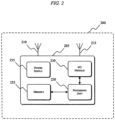
- Fig. 3 illustrates a multimode receiver 300 that includes an intermediate frequency (“IF") filter module 305, an analog-to-digital conversion (“ADC”) module 310, a first analysis module 315, a second analysis module 320, a third analysis module 325, and a classification module 330.
- the receiver 300 can, for example, be included in the device 200 and be configured to receive a signal from another device within the communications system 100, determine a corresponding communication mode for the received signal, and be configured to receive signals according the determined communications mode.
- the receiver 300 is configured for cost-effective, multimode signal acquisition of signals of a plurality of different communication modes that operate within the same frequency band.
- Such communication modes include, for example, the FSK, OFDM, and O-QPSK communication modes of the IEEE 802.15.4g standard, the IEEE 802.11 standard, etc., operating in the 902MHz-928MHz industrial, scientific, and medical (“ISM”) frequency bands.
- ISM industrial, scientific, and medical
- the IF filter 305 is configured to shift the received signal's carrier frequency to an intermediate range of frequencies that is more suitable for processing and analysis.
- the filtered output of the IF filter 305 is provided to the ADC module 310 for sampling.
- the sampled output of the ADC module 310 is then provided to the first analysis module 315, the second analysis module 320, and the third analysis module 325.
- the receiver 300 can include additional or fewer analysis models, depending on the embodiment of the invention.
- Each of the illustrated analysis modules 315, 320, and 325 is configured to execute one or more frequency analysis processes for determining a characteristic of the received signal (e.g., amplitude, power, PSD, etc.).
- the analysis modules 315, 320, and 325 are configured to analyze the preamble or syncword of a received signal to identify its corresponding communication mode.
- the preamble is used to identify the start of the data within a bit stream of data.
- the spectral content of the preamble can vary. As a result, by analyzing specific frequencies or ranges of frequencies related to the received preamble, the corresponding communication mode can be identified.
- each of the analysis modules 315, 320, and 325 is configured to execute instructions stored in, for example, the memory 225 of the controller 205 for performing a Goertzel analysis to identifying characteristics of specific frequency components of the received signal or a portion of the received signal (e.g., the preamble of the received signal).
- the Goertzel analysis includes executing one or more Goertzel algorithms for various communication modes. Depending on the communication mode, the Goertzel algorithm can be tuned to different frequencies of interest.
- an analysis module executes a Goertzel algorithm to compute a sequence, s(n) , given an input sequence x(n), as shown below in EQN. 1.
- s n x n + 2 cos 2 ⁇ s n ⁇ 1 ⁇ s n ⁇ 2
- ⁇ is a frequency of interest.
- the z-transform of EQN. 1 produces EQN. 2 below.
- the above transform and the operation of the analysis modules 315, 320, and 325 can be expanded to identify characteristics of multiple frequencies of interest within the received baseband signal.
- the Goertzel technique described above can be applied for the FSK modes of the IEEE 802.15.4g standard. These FSK modes have a set of candidate frequencies corresponding to baud rates for the received signal (e.g., 25 kHz, 75 kHz, 100 kHz, 150 kHz, 250 kHz, etc.).
- a range or window of frequencies around each of the candidate frequencies is used to allow for variance in the received signals without affecting the identification of the communication mode.
- Candidate frequencies for other communication modes can similarly by identified using the analysis modules 315, 320, and 325.
- the analysis modules 315, 320, and 325 can also be used to identify the baud rate of a received signal.
- the outputs of each of the analysis modules 315, 320, and 325 are then provided to the classification module 330.
- the classification module 330 determines the communication mode of the received signal by comparing a value for a characteristic (e.g., amplitude, power, PSD, etc.) of the received signal with one or more expected characteristic values at each candidate frequency for the various communication modes.
- a characteristic e.g., amplitude, power, PSD, etc.
- the receiver 300 is able to use relationships between the power associated with the received signal at the candidate frequencies and a plurality of communication modes to identify the communication mode of the received signal.
- the relationships between a power of a received signal at the candidate frequencies and the expected power at the candidate frequencies for each of the plurality of communication modes are stored in memory (e.g., the memory 225).
- the relationships can be stored as one or more functions, one or more look up tables ("LUTs"), or as a series of thresholds to which the power for particular frequencies may be compared.
- LUTs look up tables
- values of, for example, amplitude, power, PSD, or another characteristic are stored in memory corresponding to a plurality of frequencies of interest for various communication modes.
- 8-bit numbers i.e., 256 values
- 16-bit numbers i.e., 65,536 values
- the resolution of the characteristic value comparison is based on the resolution of the ADC module 310 used for sampling the received signal. The characteristic value is then used as an input value that is compared to the values stored in the LUT for the various communication modes.
- the LUT entry or entries that correspond to the characteristic value of the received signal is then identified by the classification module 330. Additional comparisons can be made to determine whether the received signal is associated with a known communication mode. If there is a sufficient correlation between the received signal and the expected characteristic values, the classification module 330 identifies the communication mode of the received signal. A sufficient correlation may be identified using, for example, a predetermined or calculated percent error value, an error range, etc. Additionally or alternatively, the classification module 330 may have to identify a characteristic value at each of the expected frequencies in the received signal before identifying the communication mode. In such embodiments, the identification of the communication mode may not be made if one or more frequencies or frequency components of sufficient amplitude, power, PSD, etc., are not present. With respect to implementations of the invention that use a variety of threshold values, the characteristic value can be compared sequentially to a series of threshold values. The threshold values correspond to values of the characteristic at the specified frequencies that are indicative of a particular communication mode.
- the preamble of a single carrier signal operating at the matching baud rate is likely being received.
- the device 200 can then be automatically reconfigured for full acquisition of signals transmitted using the identified communication mode (e.g., the preamble for the identified communication mode is then assumed to be received). If multiple matches are found, a multi-carrier signal spanning the detected tones is likely being received. The device 200 can then be automatically reconfigured accordingly for the full acquisition of such signals.
- Figs. 4 and 5 illustrate PSD plots 400 and 500, respectively, of two different communication modes.
- PSD is illustrated in units of power (decibels ["dB"]) per Hertz ("Hz").
- the PSDs 405 and 410 for a first communication mode and a 50 kbps data link with modulation indices, h, of 0.5 and 1.0, respectively, are shown.
- the energy spectral density (“ESD”) can be used in place of or in addition to the PSD.
- the signal preamble for the illustrated communication mode has characteristic frequency peaks that can be used to identify the communication mode of the received signal.
- executing a Goertzel algorithm as described above with frequencies of interest at 300 kHz and one or more other frequencies, and then comparing the outputs of the Goertzel algorithm to predetermined power density levels (e.g., -50 dB/Hz), allows the receiver 300 to identify the communication mode.
- the PSDs 505 and 510 for a second communication mode and a 200 kbps data link with modulation indices, h, of 0.5 and 1.0, respectively, are shown.
- the frequencies of interest for this communication mode may be 100 kHz, 200 kHz, 300 kHz, 400 kHz, and/or 500 kHz.
- the number of frequencies of interest used to identify a communication mode can be varied based on, for example, a range of possible frequencies associated with a communication mode. If the output of a corresponding analysis module indicates that the preamble of the received signal includes frequency components at the frequencies of interest that are each above a PSD of, for example, -70 dB/Hz, the associated communication mode can be identified.
- the communication mode of the received signal can be quickly and efficiently identified.
- a frequency analysis e.g., Goertzel analysis
- a characteristic e.g., PSD
- AGC automatic gain control
- a set of incoming signal samples, x, a vector of desired frequencies, F, and a vector of estimated incoming signal powers, P, at the desired frequencies can be used to classify incoming signals.
- the vector of desired frequencies, F corresponds to the baud rates of single-carrier modes of interest and/or the tones of multi-carrier modes of interest.
- the below pseudo-code is exemplary of an embodiment of the invention for classifying the communication mode of an incoming signal using the Goertzel algorithm.
- the vector of estimated incoming signal powers, P is populated by calculating a power value for each of the frequencies of interest in the vector of desired frequencies, F, as shown below.
- a threshold value at exactly one location, j within the vector of estimated incoming signal powers, P, then a single carrier signal is detected having a corresponding baud rate, F[j]. If the power of an incoming signal is greater than at least one threshold value at multiple locations (e.g., ⁇ j l , ... , j n ⁇ ), then a multi-carrier signal is detected that spans the tones ⁇ F(j l , ... j n ) ⁇ . If the power at a midpoint of the locations j l and j n (e.g., between two tones) is less than one or more threshold values, then the detected multi-carrier signal is an OFDM signal.
- Further processing can also be performed to classify a detected single-carrier signal by analyzing a ratio of the power at a particular frequency (e.g., the frequency at which the signal power is greater than the threshold value) to the power at the frequency corresponding to the carrier signal. Such an analysis can be used to estimate a modulation index of a single-carrier signal modulated using FSK.
- a process 600 for determining a communication mode of a received signal is shown in Fig. 6 .
- the process 600 begins with the reception of a signal (step 605).
- the signal is, for example, an analog signal that has been transmitted according to a particular modulation or transmission technique, such as FSK, PSK, QPSK, O-QPSK, OFDM, etc., as previously indicated.
- the received analog signal is then filtered (step 610). Filtering the received analog signal can include the use of an IF filter that shifts the frequency of the carrier signal to a lower frequency for processing and analysis.
- the IF filter is associated with a tunable local oscillator ("LO").
- the filtered output of the IF filter is provided to an analog-to-digital converter ("ADC") (step 615) for conversion to a digital signal (i.e., sampling).
- ADC analog-to-digital converter
- the sampled signal is then provided to one or more analysis modules which perform frequency analysis on the digital form of the received signal (step 620).
- the frequency analysis can be performed in a number of ways. For example, a Goertzel algorithm, a discrete Fourier transform (“DFT”), a fast Fourier transform (“FFT”), a Cooley-Tukey FFT algorithm, etc.
- DFT discrete Fourier transform
- FFT fast Fourier transform
- Cooley-Tukey FFT algorithm a Cooley-Tukey FFT algorithm
- different frequency analysis techniques can be used to identify different communication modes. The selection of a frequency analysis technique may be based on the factors such as computational complexity, available hardware resources, power requirements, etc.
- the Goertzel algorithm is used because it can be tuned to specific frequencies and can be implemented using fewer mathematical operations (e.g., additions, subtractions, multiplications, etc.). Additionally or alternatively, another technique designed to identify or analyze specific frequencies or a narrow band of frequencies can be used to identify the characteristics of the preamble a received signal. As a result, the hardware resources required to implement the multimode receiver can be reduced, the power required to perform the frequency analysis can be reduced, and the amount of time required to complete the analysis can be reduced.
- the number of analysis modules present in the multimode receiver can vary depending upon the number of different communication modes the receiver is configured to identify (e.g., one analysis module for each communication mode).
- the outputs of the analysis modules are provided to a classification module.
- the classification module compares, for example, a PSD for one or more frequencies of interest specific to the different communication modes to predetermined PSD values at those specific frequencies for each of the communication modes. Based upon the comparisons of the PSD values for the various communication modes, the communication mode may be determined (step 625). Following the determination of the communication mode, the multimode receiver is configured (e.g., automatically configured or reconfigured) for the full acquisition of signals transmitted according to the determined communication mode (step 630).
- the invention provides, among other things, systems and methods for acquiring communication signals transmitted according to different communication modes.
- Various features and advantages of the invention are set forth in the following claims.
Landscapes
- Engineering & Computer Science (AREA)
- Computer Networks & Wireless Communication (AREA)
- Signal Processing (AREA)
- Mobile Radio Communication Systems (AREA)
- Digital Transmission Methods That Use Modulated Carrier Waves (AREA)
- Monitoring And Testing Of Transmission In General (AREA)
- Transceivers (AREA)
- Circuits Of Receivers In General (AREA)
Description
- The present invention relates to the acquisition of signals transmitted using a variety of different communication modes.
- Current techniques for acquiring communications signals of different communication modes at a single receiver use mode switching (e.g., based on the IEEE 802.15.4g standard). Mode switching allows for a plurality of communication modes to be supported by a single receiver by utilizing a common initial communication mode. For example, as a part of a common initial communication mode between a transmitter and a receiver, a specific communication mode for the signals that are to be subsequently received is provided to the receiver. The receiver is then able to be switched or configured to receive the signals corresponding to that specific communication mode.
-
EP2066043 describes a cell search method for a multi-mode telecommunication apparatus. The method comprises receiving signals present in a frequency range; transforming received signals into frequency domain; estimating power spectral density from transformed signals; estimating probability of different communication modes by correlating the estimated power spectral density with power spectral density signatures of said different communication modes; and performing cell search according to estimated most probable communication mode. - Although the use of a common initial communication mode can be effective for implementing a receiver that is capable of receiving signals of multiple modes, such a technique has limited applicability due to its strict requirements for common mode operation. Requiring that all initial communication occur using the same common mode is difficult or impossible to enforce, for example, when the signals being exchanged are associated with different communications standards (e.g., IEEE 802.11, IEEE 802.15, IEEE 802.16, etc.). Additionally, requiring a common initial communication mode can also increase the computational resources required for multimode signal acquisition, as well as the power consumed by the receiver.
- As such, the present disclosure provides cost-effective systems and methods for the acquisition of signals of different communication modes. The invention to which this European patent relates is defined in the appended claims.
- According to an example which does not fall within the wording of the appended claims, disclosed herein is a system for transmitting and receiving signals over a network. The system includes a receiver that is configured for multimode signal acquisition. The receiver includes a filter module, a sampling module, a first analysis module, a second analysis module, and a classification module. The filter module is configured to filter a received signal and to generate a filtered signal. The sampling module is configured to sample the filtered signal and to generate a sampled signal. The first analysis module is configured to analyze at least one characteristic of the sampled signal associated with a first predetermined frequency. The first analysis module is also configured to generate a first output signal associated with the at least one characteristic. The second analysis module is configured to analyze the at least one characteristic of the sampled signal associated with a second predetermined frequency. The second analysis module is also configured to generate a second output signal associated with the at least one characteristic. The classification module is configured to classify the received signal into one of a plurality of different communication modes based on the first output from the first analysis module and the second output from the second analysis module.
- According to another example which does not fall within the wording of the appended claims, also disclosed herein is a method of multimode signal acquisition in a receiver. The method includes receiving a communication signal associated with one of a plurality of different communication modes, sampling the communication signal to generate a sampled signal, and analyzing at least one characteristic of the sampled signal associated with a first predetermined frequency. A first output signal associated with the at least one characteristic is then generated. The method also includes analyzing the at least one characteristic of the sampled signal associated with a second predetermined frequency, generating a second output signal associated with the at least one characteristic, and classifying the received signal into one of the plurality of different communication modes based on the first output signal and the second output signal.
- According to another example which does not fall within the wording of the appended claims, also disclosed herein is a device that is configured to process digital signals. The device includes a filter module, a sampling module, a first analysis module, a second analysis module, and a classification module. The filter module is configured to filter a received signal and to generate a filtered signal. The sampling module is configured to sample the filtered signal and to generate a sampled signal. The first analysis module is configured to analyze a spectral density of the sampled signal associated with a first predetermined frequency. The first analysis module is also configured to generate a first output signal associated with the spectral density for the first predetermined frequency. The second analysis module is configured to analyze the spectral density of the sampled signal associated with a second predetermined frequency. The second analysis module is also configured to generate a second output signal associated with the spectral density for the second predetermined frequency. The classification module is configured to classify the received signal into one of a plurality of different communication modes based on the first output from the first analysis module and the second output from the second analysis module.
- According to another example which does not fall within the wording of the appended claims, also disclosed herein is a method of transmitting a plurality of signals of different communication modes to, and receiving the plurality of signals at, a receiver. The method includes transmitting a first signal from a first transmitter to the receiver. The first signal is transmitted according to a first communication mode. The method also includes transmitting a second signal from a second transmitter to the receiver. The second signal is transmitted according to a second communication mode, and the first communication mode is different than the second communication mode. The first signal and the second signal are transmitted to the receiver without a common initial communication mode.
- Other examples will become apparent by consideration of the detailed description and accompanying drawings.
-
-
Fig. 1 illustrates a communications system according to one embodiment of the invention. -
Fig. 2 illustrates a network device according to one embodiment of the invention. -
Fig. 3 illustrates a receiver according to one embodiment of the invention. -
Fig. 4 is a diagram of a power spectral density estimate for a signal transmitted according to a first communication mode. -
Fig. 5 is a diagram of a power spectral density estimate for a signal transmitted according to a second communication mode. -
Fig. 6 is a process for acquiring multimode signals according to an embodiment of the invention. - Before any embodiments of the invention are explained in detail, it is to be understood that the invention is not limited in its application to the details of construction and the arrangement of components set forth in the following description or illustrated in the following drawings. The invention is capable of other embodiments and of being practiced or of being carried out in various ways.
- Embodiments of the invention relate to systems and methods for multimode signal acquisition within a network, such as a utility communications network. Such systems include, for example, multimode receivers that are configured to efficiently and effectively identify a communication mode for an incoming or received signal with reduced or limited computational (e.g., processing, memory, etc.) and power requirements. The multimode receivers can include, among other things, one or more analysis modules for analyzing a characteristic of a received signal (e.g., amplitude, power, power spectral density ["PSD"], etc.) or a portion of the received signal (e.g., a preamble or syncword, header, etc.). Such a multimode receiver can be configured to execute computer readable instructions corresponding to a process for determining or identifying a communication mode of the received signal. The process includes, among other things, receiving a signal (e.g., a modulated analog signal) from another device. The received signal may have been modulated using any of a variety of modulation and/or transmission techniques, such as amplitude shift keying ("ASK"), frequency shift keying ("FSK"), phase shift keying ("PSK"), quadrature amplitude modulation ("QAM"), binary FSK ("BFSK"), minimum FSK ("MSK"), multiple FSK ("MFSK"), differential PSK ("DPSK"), binary PSK ("BPSK"), quadrature PSK ("QPSK"), offset QPSK ("O-QPSK"), orthogonal frequency division multiplexing ("OFDM"), etc. The received analog signal is then filtered using an intermediate frequency ("IF") filter that shifts the frequency of the carrier signal to a lower frequency for processing and analysis.
- Following analog-to-digital conversion, the signal is provided to one or more analysis modules which perform frequency analysis on the digital form of the received signal. The frequency analysis can be performed in a number of different ways (e.g., using a Goertzel algorithm). After the characteristics of the signals have been analyzed, the outputs of the analysis modules are provided to a classification module. The classification module compares, for example, a PSD for one or more frequencies of interest specific to the different communication modes to predetermined PSD values at the frequencies of interest for each of the communication modes. Based upon the comparisons of the PSD values for the various communication modes, the communication mode may be determined, and the multimode receiver can be configured for the full acquisition of signals transmitted according to the determined communication mode. As such, the communication mode can be determined without requiring additional information to be transmitted through the utility communications network. Additionally, because the communication mode can be determined based on a portion of the received signal (e.g., the preamble) at a relatively low frequency, the frequencies of interest for which analysis is performed can be well-defined and are within a relatively narrow band of frequencies.
-
Fig. 1 illustrates a generalized communications system 100 (e.g., a utility communications system or network) that includes a first back office system ("BOS") 105, asecond BOS 110, acommunications network 115, a domain name system or server ("DNS") 120, anaccess point 125, alocal network 130, and nodes 135-145. The nodes 135-145 communicate through thenetwork 130, such as a local area network ("LAN"), a neighborhood area network ("NAN"), a home area network ("HAN"), or personal area network ("PAN") using any of a variety of communications protocols, such as Wi-Fi, Bluetooth, ZigBee, etc. This network is, in turn, configured for communication with theaccess point 125, which is also associated with thecommunications network 115. Thecommunications network 115 is, for example, a wide area network ("WAN") (e.g., a TCP/IP based network, a Global System for Mobile Communications ["GSM"] network, a General Packet Radio Service ["GPRS"] network, a Code Division Multiple Access ["CDMA"] network, an Evolution-Data Optimized ["EV-DO"] network, an Enhanced Data Rates for GSM Evolution ["EDGE"] network, a 3GSM network, a Digital Enhanced Cordless Telecommunications ["DECT"] network, a Digital AMPS ["IS-136/TDMA"] network, an Integrated Digital Enhanced Network ["iDEN"] network, a Digital Advanced Mobile Phone System ["D-AMPS"] network, etc.). - The connections between the nodes 135-145 and the
network 130, and the connections between thenetwork 130 and theaccess point 125 are, for example, wired connections, wireless connections, or a combination of wireless and wired connections. In some embodiments, the nodes 135-145 communicate through thenetwork 130 using wireless communications, and thefirst access point 125 communicates through thenetwork 130 using a wired network connection. - In some embodiments, the networks described above are, for example, self-configuring or mobile ad hoc networks ("MANETs") which utilize a mesh network topology to provide redundancy to the
communications system 100. In other embodiments, the networks have different network topologies, such as ring, star, line, tree, bus, or fully-connected network topologies. In the illustrated embodiment, the networks and the communication between the devices associated with the networks can be protected using one or more encryption techniques, such as those techniques provided in the IEEE 802.1 standard for port-based network security, pre-shared key, Extensible Authentication Protocol ("EAP"), Wired Equivalency Privacy ("WEP"), Temporal Key Integrity Protocol ("TKIP"), Wi-Fi Protected Access ("WPA"), etc. - The
DNS 120 connects to network 130 through theaccess point 125. In other embodiments, theDNS 120 connects to thenetwork 130 through thecommunications network 115 and then through theaccess point 125. In some embodiments, theDNS 120 is capable of receiving and processing dynamic updates to provide a dynamic DNS ("DDNS") service. Messages sent from theBOSs network 130 are sent by way of unique network addresses associated with the one or more nodes and registered with theDNS 120. In some embodiments, theDNS 120 is dedicated to a single LAN, or is shared by a plurality of LANs. TheDNS 120 maintains network addresses for the nodes 135-145 and thenetwork 130. The network addresses for the nodes 135-145 are stored or maintained in, for example, a node route registry. In some embodiments, theDNS 120 also maintains address allocation information, such as a node address allocation indicator or node preference indicator. The network registration and communication process for a node within a communications system, such assystem 100, is described in greater detail inU.S. Patent Publication No. 2008/0189436, entitled "METHOD AND SYSTEM OF PROVIDING IP-BASED PACKET COMMUNICATIONS IN A UTILITY NETWORK," filed May 24, 2007 . - The
first BOS 105 and thesecond BOS 110 are implemented as a single device, a combination of devices, a network management system, a server, one or more computers, one or more network devices, one or more communications devices, one or more software applications, or a variety of components that is/are capable of communicating with one or more of theaccess point 125 or nodes 135-145 via thecommunications network 115. Thefirst BOS 105 and thesecond BOS 110 are, for example, associated with one or more utility providers, credit card companies, other financial institutions, etc. -
Fig. 2 illustrates adevice 200 such as a node, an access point, a BOS, or another component or device of thecommunications system 100 that includes, among other things, a control unit orcontroller 205, afirst radio 210, and asecond radio 215. Thedevice 200 can be configured as a transmitter, a receiver, or both a transmitter and a receiver. Thecontroller 205 includes, for example, a control orprocessing unit 220, amemory 225, an input/output ("I/O")module 230, apower supply module 235, and one or more busses for operably and communicatively coupling the components within thecontroller 205. Theprocessing unit 220 is, for example, a processor, a microprocessor, a microcontroller, etc. Thememory 225 includes, for example, a read-only memory ("ROM"), a random access memory ("RAM"), an electrically erasable programmable read-only memory ("EEPROM"), a flash memory, a hard disk, an SD card, or another suitable magnetic, optical, physical, or electronic memory device. The I/O module 230 can include routines for sending information to and receiving information from components or devices external to thecontroller 205 and for transferring information between components within thecontroller 205. Software included in the implementation of thedevice 200 can be stored in thememory 225 of thecontroller 205. The software includes, for example, firmware applications and other executable instructions for performing the methods described herein. In other embodiments, thecontroller 205 can include additional, fewer, or different components. - The
controller 205 can be implemented partially or entirely on one or more semiconductor chips (e.g., an application-specific integrated circuit ["ASIC"], a system-on-a-chip ["SOC"], etc.). In some embodiments, one or more field-programmable gate arrays ["FPGA"] semiconductor chips can be used, such as a chip developed through a register transfer level ("RTL") design process. In various embodiments of the invention, thecontroller 205 can be implemented at least partially on, for example, one or more printed circuit boards ("PCBs") within thedevice 200. For example, the PCB is populated with a plurality of electrical and electronic components which provide operational control and protection to thedevice 200. The PCB also includes, among other things, a plurality of additional passive and active components such as resistors, capacitors, inductors, integrated circuits, and amplifiers. These components are arranged and connected to provide a plurality of electrical functions to the PCB including, among other things, filtering, signal conditioning, and voltage regulation. For descriptive purposes, the PCB and the electrical components populated on the PCB are collectively referred to as thecontroller 205. Thecontroller 205 receives signals from theradios device 200, conditions and processes the signals, and transmits processed and conditioned signals to, for example, another component or device within theutility communications network 100, etc. - The
power supply module 235 includes a power source, such as batteries, a battery pack, a mains power plug, etc. In embodiments of the invention which include batteries, the batteries are alkaline-based or lithium-based batteries and are, for example, disposable or rechargeable AA batteries, AAA batteries, six-volt ("6V") batteries, nine-volt ("9V") batteries, etc. -
Fig. 3 illustrates amultimode receiver 300 that includes an intermediate frequency ("IF")filter module 305, an analog-to-digital conversion ("ADC")module 310, afirst analysis module 315, asecond analysis module 320, athird analysis module 325, and aclassification module 330. Thereceiver 300 can, for example, be included in thedevice 200 and be configured to receive a signal from another device within thecommunications system 100, determine a corresponding communication mode for the received signal, and be configured to receive signals according the determined communications mode. For example, thereceiver 300 is configured for cost-effective, multimode signal acquisition of signals of a plurality of different communication modes that operate within the same frequency band. Such communication modes include, for example, the FSK, OFDM, and O-QPSK communication modes of the IEEE 802.15.4g standard, the IEEE 802.11 standard, etc., operating in the 902MHz-928MHz industrial, scientific, and medical ("ISM") frequency bands. - The
IF filter 305 is configured to shift the received signal's carrier frequency to an intermediate range of frequencies that is more suitable for processing and analysis. The filtered output of theIF filter 305 is provided to theADC module 310 for sampling. The sampled output of theADC module 310 is then provided to thefirst analysis module 315, thesecond analysis module 320, and thethird analysis module 325. Although three analysis modules are illustrated, thereceiver 300 can include additional or fewer analysis models, depending on the embodiment of the invention. Each of the illustratedanalysis modules - In some embodiments, the
analysis modules analysis modules memory 225 of thecontroller 205 for performing a Goertzel analysis to identifying characteristics of specific frequency components of the received signal or a portion of the received signal (e.g., the preamble of the received signal). The Goertzel analysis includes executing one or more Goertzel algorithms for various communication modes. Depending on the communication mode, the Goertzel algorithm can be tuned to different frequencies of interest. - For example, in a general implementation, an analysis module executes a Goertzel algorithm to compute a sequence, s(n), given an input sequence x(n), as shown below in EQN. 1.


- Applying an additional finite impulse response ("FIR") transform in the form of EQN. 3 below


- The above transform and the operation of the
analysis modules analysis modules analysis modules - The outputs of each of the
analysis modules classification module 330. Theclassification module 330 determines the communication mode of the received signal by comparing a value for a characteristic (e.g., amplitude, power, PSD, etc.) of the received signal with one or more expected characteristic values at each candidate frequency for the various communication modes. - For example, the
receiver 300 is able to use relationships between the power associated with the received signal at the candidate frequencies and a plurality of communication modes to identify the communication mode of the received signal. For example, the relationships between a power of a received signal at the candidate frequencies and the expected power at the candidate frequencies for each of the plurality of communication modes are stored in memory (e.g., the memory 225). The relationships can be stored as one or more functions, one or more look up tables ("LUTs"), or as a series of thresholds to which the power for particular frequencies may be compared. - With respect to implementations of the invention in which a LUT is used, values of, for example, amplitude, power, PSD, or another characteristic are stored in memory corresponding to a plurality of frequencies of interest for various communication modes. In some embodiments, 8-bit numbers (i.e., 256 values) or 16-bit numbers (i.e., 65,536 values) are used to identify the characteristic value of a received signal at a particular frequency. In some embodiments, the resolution of the characteristic value comparison is based on the resolution of the
ADC module 310 used for sampling the received signal. The characteristic value is then used as an input value that is compared to the values stored in the LUT for the various communication modes. The LUT entry or entries that correspond to the characteristic value of the received signal is then identified by theclassification module 330. Additional comparisons can be made to determine whether the received signal is associated with a known communication mode. If there is a sufficient correlation between the received signal and the expected characteristic values, theclassification module 330 identifies the communication mode of the received signal. A sufficient correlation may be identified using, for example, a predetermined or calculated percent error value, an error range, etc. Additionally or alternatively, theclassification module 330 may have to identify a characteristic value at each of the expected frequencies in the received signal before identifying the communication mode. In such embodiments, the identification of the communication mode may not be made if one or more frequencies or frequency components of sufficient amplitude, power, PSD, etc., are not present. With respect to implementations of the invention that use a variety of threshold values, the characteristic value can be compared sequentially to a series of threshold values. The threshold values correspond to values of the characteristic at the specified frequencies that are indicative of a particular communication mode. - If one match to a communication mode is found, then the preamble of a single carrier signal operating at the matching baud rate is likely being received. The
device 200 can then be automatically reconfigured for full acquisition of signals transmitted using the identified communication mode (e.g., the preamble for the identified communication mode is then assumed to be received). If multiple matches are found, a multi-carrier signal spanning the detected tones is likely being received. Thedevice 200 can then be automatically reconfigured accordingly for the full acquisition of such signals. -
Figs. 4 and5 illustratePSD plots Fig. 4 , thePSDs PSDs receiver 300 to identify the communication mode. InFig. 5 , thePSDs - By performing a frequency analysis (e.g., Goertzel analysis) of the frequencies associated with a portion of a received signal (e.g., the preamble), and comparing a characteristic (e.g., PSD) at those frequencies to expected characteristic values for various communication modes, the communication mode of the received signal can be quickly and efficiently identified. Such a technique also reduces the computational requirements of the
multimode receiver 300, as well as the amount of power that is consumed in determining the communication mode. In some embodiments, automatic gain control ("AGC") can also be performed prior to determining the communication mode. - As an illustrative example, a set of incoming signal samples, x, a vector of desired frequencies, F, and a vector of estimated incoming signal powers, P, at the desired frequencies can be used to classify incoming signals. The vector of desired frequencies, F, corresponds to the baud rates of single-carrier modes of interest and/or the tones of multi-carrier modes of interest. The below pseudo-code is exemplary of an embodiment of the invention for classifying the communication mode of an incoming signal using the Goertzel algorithm. The vector of estimated incoming signal powers, P, is populated by calculating a power value for each of the frequencies of interest in the vector of desired frequencies, F, as shown below.

- If the power of an incoming signal is greater than a threshold value at exactly one location, j, within the vector of estimated incoming signal powers, P, then a single carrier signal is detected having a corresponding baud rate, F[j]. If the power of an incoming signal is greater than at least one threshold value at multiple locations (e.g., {jl, ... , jn}), then a multi-carrier signal is detected that spans the tones {F(jl, ... jn)}. If the power at a midpoint of the locations jl and jn (e.g., between two tones) is less than one or more threshold values, then the detected multi-carrier signal is an OFDM signal. Further processing can also be performed to classify a detected single-carrier signal by analyzing a ratio of the power at a particular frequency (e.g., the frequency at which the signal power is greater than the threshold value) to the power at the frequency corresponding to the carrier signal. Such an analysis can be used to estimate a modulation index of a single-carrier signal modulated using FSK.
- A
process 600 for determining a communication mode of a received signal is shown inFig. 6 . Theprocess 600 begins with the reception of a signal (step 605). The signal is, for example, an analog signal that has been transmitted according to a particular modulation or transmission technique, such as FSK, PSK, QPSK, O-QPSK, OFDM, etc., as previously indicated. The received analog signal is then filtered (step 610). Filtering the received analog signal can include the use of an IF filter that shifts the frequency of the carrier signal to a lower frequency for processing and analysis. In some embodiments, the IF filter is associated with a tunable local oscillator ("LO"). - Following
step 610, the filtered output of the IF filter is provided to an analog-to-digital converter ("ADC") (step 615) for conversion to a digital signal (i.e., sampling). The sampled signal is then provided to one or more analysis modules which perform frequency analysis on the digital form of the received signal (step 620). The frequency analysis can be performed in a number of ways. For example, a Goertzel algorithm, a discrete Fourier transform ("DFT"), a fast Fourier transform ("FFT"), a Cooley-Tukey FFT algorithm, etc. In some embodiments, different frequency analysis techniques can be used to identify different communication modes. The selection of a frequency analysis technique may be based on the factors such as computational complexity, available hardware resources, power requirements, etc. In some embodiments, the Goertzel algorithm is used because it can be tuned to specific frequencies and can be implemented using fewer mathematical operations (e.g., additions, subtractions, multiplications, etc.). Additionally or alternatively, another technique designed to identify or analyze specific frequencies or a narrow band of frequencies can be used to identify the characteristics of the preamble a received signal. As a result, the hardware resources required to implement the multimode receiver can be reduced, the power required to perform the frequency analysis can be reduced, and the amount of time required to complete the analysis can be reduced. The number of analysis modules present in the multimode receiver can vary depending upon the number of different communication modes the receiver is configured to identify (e.g., one analysis module for each communication mode). After the frequency content of the signals has been analyzed, the outputs of the analysis modules are provided to a classification module. The classification module compares, for example, a PSD for one or more frequencies of interest specific to the different communication modes to predetermined PSD values at those specific frequencies for each of the communication modes. Based upon the comparisons of the PSD values for the various communication modes, the communication mode may be determined (step 625). Following the determination of the communication mode, the multimode receiver is configured (e.g., automatically configured or reconfigured) for the full acquisition of signals transmitted according to the determined communication mode (step 630). - Thus, the invention provides, among other things, systems and methods for acquiring communication signals transmitted according to different communication modes. Various features and advantages of the invention are set forth in the following claims.
Claims (15)
- A device (300) configured to process digital signals, the device comprising:a sampling module (310) configured to sample a received signal to generate a sampled signal;one or more analysis modules (315, 320, 325), a respective analysis module (315) of the one or more analysis modules configured to analyze a characteristic of the sampled signal associated with a respective plurality of windows of frequencies associated with a respective communication mode of a plurality of communication modes to generate one or more respective values for the characteristic, wherein the characteristic comprises one or more of amplitude, power, or power spectral density; anda classification module (330) configured to determine a communication mode of the received signal from the plurality of communication modes based on the one or more respective values.
- The network device of claim 1, wherein the respective analysis module (315, 320, 325) is configured to execute at least one of a Goertzel algorithm, a discrete Fourier transform, a fast Fourier transform, or a Cooley to Tukey fast Fourier transform algorithm.
- The network device of claim 1 or 2, wherein the network device (300) is associated with a node (135, 140, 145) within a utility communications network (130).
- The network device of any one of claims 1 to 3, wherein the network device (300) is implemented as an application specific integrated circuit.
- A system (100) comprising:
a receiver (300) configured for multimode signal acquisition, the receiver (300) including a device according to any of claims 1 to 4. - The system of claim 5, further comprising a transmitter.
- A method of multimode signal acquisition in a receiver, the method comprising:receiving (605) a communication signal associated with one of a plurality of different communication modes;sampling (615) the communication signal to generate a sampled signal;analyzing (620) at least one characteristic of the sampled signal associated with a first plurality of windows of frequencies associated with a first communication mode of the plurality of communication modes, the at least one characteristic comprising one or more of amplitude, power, or power spectral density;generating one or more first values associated with the at least one characteristic;analyzing (620) the at least one characteristic of the sampled signal associated with a second plurality of windows of frequencies associated with a second communication mode of the plurality of communication modes, the first plurality of windows of frequencies being different from the second plurality of windows of frequencies;generating one or more second values associated with the at least one characteristic; andclassifying (625) the received signal into one of the plurality of different communication modes based on the one or more first values and the one or more second values.
- The method of claim 8, further comprising:filtering (610) the communication signal to generate a filtered signal; andsampling (615) the filtered signal to generate the sampled signal.
- The method of claim 8, wherein filtering the communication signal comprises shifting a frequency of the communication signal to a lower frequency.
- The method of any one of claims 7 to 9, wherein classifying the received signal into one of the plurality of different communication modes based on the first output signal and the second output signal comprises:comparing the one or more first values with one or more expected characteristics of the first communication mode; andcomparing the one or more second values with one or more expected characteristics of the second communication mode.
- The method of any one of claims 7 to 10, wherein respective windows of the first plurality of windows of frequencies are arranged around respective predetermined frequencies.
- The method of any one of claims 7 to 11, wherein analyzing (620) the at least one characteristic of the sampled signal associated with the first plurality of windows of frequencies comprises performing at least one of a Goertzel algorithm, a discrete Fourier transform, a fast Fourier transform, or a Cooley to Tukey fast Fourier transform algorithm.
- The method according to any of claims 7 to 12, wherein the first of the plurality of different communication modes and the second of the plurality of different communication modes are each selected from the group consisting of an amplitude shift keying "ASK" communication mode, a frequency shift keying "FSK" communication mode, a phase shift keying "PSK" communication mode, a quadrature amplitude modulation "QAM" communication mode, a quadrature PSK "QPSK" communication mode, an offset QPSK "O-QPSK" communication mode, and an orthogonal frequency division multiplexing "OFDM" communication mode.
- A memory (225) storing computer to readable instructions, the instructions, when executed by a controller (205), are configured to cause the controller (205) to perform the method of any one of claims 7 to 13.
- A network device (200) comprising:a memory (225) storing computer readable instructions; anda processing unit (220), that when executing the computer readable instructions, is configured to perform the method of any one of claims 7 to 13.
Applications Claiming Priority (2)
| Application Number | Priority Date | Filing Date | Title |
|---|---|---|---|
| US13/190,800 US20130028306A1 (en) | 2011-07-26 | 2011-07-26 | Systems and methods for multimode signal acquisition |
| EP12005175.0A EP2552070B1 (en) | 2011-07-26 | 2012-07-13 | Device and method for multimode signal acquisition |
Related Parent Applications (2)
| Application Number | Title | Priority Date | Filing Date |
|---|---|---|---|
| EP12005175.0A Division-Into EP2552070B1 (en) | 2011-07-26 | 2012-07-13 | Device and method for multimode signal acquisition |
| EP12005175.0A Division EP2552070B1 (en) | 2011-07-26 | 2012-07-13 | Device and method for multimode signal acquisition |
Publications (2)
| Publication Number | Publication Date |
|---|---|
| EP4117246A1 EP4117246A1 (en) | 2023-01-11 |
| EP4117246B1 true EP4117246B1 (en) | 2024-11-06 |
Family
ID=46875607
Family Applications (2)
| Application Number | Title | Priority Date | Filing Date |
|---|---|---|---|
| EP22194073.7A Active EP4117246B1 (en) | 2011-07-26 | 2012-07-13 | Device and method for multimode signal acquisition |
| EP12005175.0A Active EP2552070B1 (en) | 2011-07-26 | 2012-07-13 | Device and method for multimode signal acquisition |
Family Applications After (1)
| Application Number | Title | Priority Date | Filing Date |
|---|---|---|---|
| EP12005175.0A Active EP2552070B1 (en) | 2011-07-26 | 2012-07-13 | Device and method for multimode signal acquisition |
Country Status (5)
| Country | Link |
|---|---|
| US (1) | US20130028306A1 (en) |
| EP (2) | EP4117246B1 (en) |
| JP (1) | JP2013051675A (en) |
| DK (1) | DK2552070T3 (en) |
| ES (2) | ES3006407T3 (en) |
Families Citing this family (9)
| Publication number | Priority date | Publication date | Assignee | Title |
|---|---|---|---|---|
| US20130099938A1 (en) * | 2011-10-21 | 2013-04-25 | Itron, Inc. | Software-defined communication unit |
| US9197467B2 (en) | 2011-10-21 | 2015-11-24 | Itron, Inc. | Multiple protocol receiver |
| DE102014219092A1 (en) * | 2014-09-22 | 2016-03-24 | Continental Teves Ag & Co. Ohg | position sensor |
| EP3101856B1 (en) * | 2015-06-03 | 2019-12-25 | ABB Schweiz AG | Method to demodulate a signal component from a sampled input signal and field bus device |
| US10481831B2 (en) * | 2017-10-02 | 2019-11-19 | Nuance Communications, Inc. | System and method for combined non-linear and late echo suppression |
| CN109587091B (en) * | 2019-01-23 | 2020-09-29 | 西南交通大学 | Modulation Format Identification Method of Coherent Optical Communication System Based on Logistic Regression Algorithm |
| US10965511B2 (en) * | 2019-08-26 | 2021-03-30 | Landis+Gyr Innovations, Inc. | Multi-PHY synchronized diversity receiver |
| JP7636729B2 (en) * | 2021-08-11 | 2025-02-27 | 株式会社村田製作所 | Spectrum analysis program, signal processing device, radar device, communication terminal, fixed communication device, and recording medium |
| US20240319356A1 (en) * | 2023-03-23 | 2024-09-26 | Nextnav, Llc | Object Detection Systems and Methods |
Family Cites Families (20)
| Publication number | Priority date | Publication date | Assignee | Title |
|---|---|---|---|---|
| US5809133A (en) * | 1996-05-24 | 1998-09-15 | Advanced Micro Devices, Inc. | DTMF detector system and method which performs frequency domain energy calculations with improved performance |
| US6285881B1 (en) * | 1996-05-31 | 2001-09-04 | Northern Telecom Ltd. | Method and system for quickly finding a control channel in a private cellular system |
| US6331996B1 (en) * | 1998-05-28 | 2001-12-18 | Lucent Technologies Inc. | Channel synchronization and impulse sounding in the presence of frequency offset |
| CA2260336A1 (en) * | 1999-02-15 | 2000-08-15 | Robert Inkol | Modulation recognition system |
| US6690746B1 (en) * | 1999-06-11 | 2004-02-10 | Southwest Research Institute | Signal recognizer for communications signals |
| US6369738B1 (en) * | 1999-08-17 | 2002-04-09 | Eric Swanson | Time domain/frequency domain data converter with data ready feature |
| US7133646B1 (en) * | 2003-12-29 | 2006-11-07 | Miao George J | Multimode and multiband MIMO transceiver of W-CDMA, WLAN and UWB communications |
| US7580444B2 (en) * | 2004-05-04 | 2009-08-25 | Her Majesty The Queen In Right Of Canada, As Represented By The Minister Of Industry, Through The Communications Research Centre Canada | Frequency hopping communication system |
| DE102005025402A1 (en) * | 2005-06-02 | 2006-12-07 | Rohde & Schwarz Gmbh & Co. Kg | Method for classifying digitally modulated signals |
| US7860146B2 (en) * | 2006-07-06 | 2010-12-28 | Gigle Networks, Inc. | Adaptative multi-carrier code division multiple access |
| US8144815B2 (en) * | 2006-11-28 | 2012-03-27 | Harris Corporation | Demand-assigned multiple access (DAMA) communication device and associated acquisition methods |
| US20080186203A1 (en) | 2007-02-02 | 2008-08-07 | Raj Vaswani | Method and system for packet transit through IPV4 networks connecting IPV6 nodes and LANs in a utility grid using tunneling technique |
| EP2165418A1 (en) * | 2007-06-15 | 2010-03-24 | Thomson Licensing | Detection of signals containing sine-wave components through measurement of the power spectral density (psd) and cyclic spectrum |
| US7680472B2 (en) * | 2007-06-21 | 2010-03-16 | Texas Instruments Incorporated | Device and method for receiving and processing RF signals, a method for providing digital calibration values for such a device and a receiver incorporating the device |
| US8254864B1 (en) * | 2007-08-09 | 2012-08-28 | Marvell Israel (M.I.S.L) Ltd. | Decreasing user equipment measurement time |
| US8145132B2 (en) * | 2007-09-17 | 2012-03-27 | Qualcomm Incorporated | Method and apparatus for reducing frequency space from frequency search |
| ATE520210T1 (en) * | 2007-11-29 | 2011-08-15 | Ericsson Telefon Ab L M | CELL SEARCHING METHOD FOR A MULTI-MODE TELECOMMUNICATIONS DEVICE, SUCH DEVICE AND A COMPUTER PROGRAM FOR EXECUTING THE METHOD |
| US20100069070A1 (en) * | 2008-09-17 | 2010-03-18 | Qualcomm Incorporated | Location-assisted network entry, scan and handover |
| EP2296273B1 (en) * | 2009-09-14 | 2013-01-23 | Nxp B.V. | Fast service scan |
| US8391345B2 (en) * | 2009-10-14 | 2013-03-05 | Qualcomm Incorporated | Power spectral distribution measurement to facilitate system acquisition |
-
2011
- 2011-07-26 US US13/190,800 patent/US20130028306A1/en not_active Abandoned
-
2012
- 2012-07-13 DK DK12005175.0T patent/DK2552070T3/en active
- 2012-07-13 EP EP22194073.7A patent/EP4117246B1/en active Active
- 2012-07-13 ES ES22194073T patent/ES3006407T3/en active Active
- 2012-07-13 EP EP12005175.0A patent/EP2552070B1/en active Active
- 2012-07-13 ES ES12005175T patent/ES2929066T3/en active Active
- 2012-07-25 JP JP2012164249A patent/JP2013051675A/en active Pending
Also Published As
| Publication number | Publication date |
|---|---|
| ES2929066T3 (en) | 2022-11-24 |
| EP2552070A2 (en) | 2013-01-30 |
| JP2013051675A (en) | 2013-03-14 |
| ES3006407T3 (en) | 2025-03-18 |
| US20130028306A1 (en) | 2013-01-31 |
| EP2552070B1 (en) | 2022-10-19 |
| EP4117246A1 (en) | 2023-01-11 |
| EP2552070A3 (en) | 2014-05-07 |
| DK2552070T3 (en) | 2023-01-09 |
Similar Documents
| Publication | Publication Date | Title |
|---|---|---|
| EP4117246B1 (en) | Device and method for multimode signal acquisition | |
| US7643811B2 (en) | Method and system for interference detection | |
| US8335536B2 (en) | Method and system for message transmission and reception | |
| Nassralla et al. | A low-complexity detection algorithm for the primary synchronization signal in LTE | |
| WO2020070594A1 (en) | Carrier frequency estimation for radio frequency fingerprinting | |
| JP2016197921A (en) | Method and device for processing interference | |
| CN112492591B (en) | Method and device for accessing power Internet of things terminal to network | |
| CN114696930B (en) | Anti-interference method, device, electronic device and storage medium for DSS | |
| Rehman et al. | Portability of an RF fingerprint of a wireless transmitter | |
| EP3121978A1 (en) | Receiving device | |
| US20100046463A1 (en) | Spectrum sharing between OFDM and non-OFDM radios | |
| Haddadin et al. | An underlay communication channel for 5G cognitive mesh networks: Packet design, implementation, analysis, and experimental results | |
| US12323810B2 (en) | Radio frequency fingerprinting within dynamic network topology | |
| CN104468443A (en) | Narrow-band interference eliminating device and method for power line communication system | |
| Ishii et al. | An adaptive receiver based on software defined radio techniques | |
| US11863424B2 (en) | Method for selecting a communication route | |
| JP3977645B2 (en) | Wireless communication system | |
| US12294473B2 (en) | Signal processing method and related devices | |
| CN118101398A (en) | Frequency deviation correction method and communication device | |
| Wang et al. | Experimental results for M-FSK signal classification and parameter estimation | |
| Kaszuba-Chęcińska et al. | Interference Resistant Waveform for Cognitive Radio MANET | |
| CN112491755A (en) | Signal processing method and device | |
| EP2640026A1 (en) | Method for estimating the frequency bandwidth of a communication channel | |
| Cardellicchio et al. | An opportunistic sensor network approach to wide area environmental sensing | |
| Erić et al. | A solution to coexistence of OFDM and FH signals based on principles of cognitive radio implemented on USRP N210 platform |
Legal Events
| Date | Code | Title | Description |
|---|---|---|---|
| PUAI | Public reference made under article 153(3) epc to a published international application that has entered the european phase |
Free format text: ORIGINAL CODE: 0009012 |
|
| STAA | Information on the status of an ep patent application or granted ep patent |
Free format text: STATUS: THE APPLICATION HAS BEEN PUBLISHED |
|
| AC | Divisional application: reference to earlier application |
Ref document number: 2552070 Country of ref document: EP Kind code of ref document: P |
|
| AK | Designated contracting states |
Kind code of ref document: A1 Designated state(s): AL AT BE BG CH CY CZ DE DK EE ES FI FR GB GR HR HU IE IS IT LI LT LU LV MC MK MT NL NO PL PT RO RS SE SI SK SM TR |
|
| STAA | Information on the status of an ep patent application or granted ep patent |
Free format text: STATUS: REQUEST FOR EXAMINATION WAS MADE |
|
| P01 | Opt-out of the competence of the unified patent court (upc) registered |
Effective date: 20230519 |
|
| 17P | Request for examination filed |
Effective date: 20230609 |
|
| RBV | Designated contracting states (corrected) |
Designated state(s): AL AT BE BG CH CY CZ DE DK EE ES FI FR GB GR HR HU IE IS IT LI LT LU LV MC MK MT NL NO PL PT RO RS SE SI SK SM TR |
|
| GRAP | Despatch of communication of intention to grant a patent |
Free format text: ORIGINAL CODE: EPIDOSNIGR1 |
|
| STAA | Information on the status of an ep patent application or granted ep patent |
Free format text: STATUS: GRANT OF PATENT IS INTENDED |
|
| INTG | Intention to grant announced |
Effective date: 20240603 |
|
| GRAS | Grant fee paid |
Free format text: ORIGINAL CODE: EPIDOSNIGR3 |
|
| GRAA | (expected) grant |
Free format text: ORIGINAL CODE: 0009210 |
|
| STAA | Information on the status of an ep patent application or granted ep patent |
Free format text: STATUS: THE PATENT HAS BEEN GRANTED |
|
| AC | Divisional application: reference to earlier application |
Ref document number: 2552070 Country of ref document: EP Kind code of ref document: P |
|
| AK | Designated contracting states |
Kind code of ref document: B1 Designated state(s): AL AT BE BG CH CY CZ DE DK EE ES FI FR GB GR HR HU IE IS IT LI LT LU LV MC MK MT NL NO PL PT RO RS SE SI SK SM TR |
|
| REG | Reference to a national code |
Ref country code: GB Ref legal event code: FG4D |
|
| REG | Reference to a national code |
Ref country code: CH Ref legal event code: EP |
|
| REG | Reference to a national code |
Ref country code: DE Ref legal event code: R096 Ref document number: 602012081202 Country of ref document: DE |
|
| REG | Reference to a national code |
Ref country code: IE Ref legal event code: FG4D |
|
| REG | Reference to a national code |
Ref country code: LT Ref legal event code: MG9D |
|
| REG | Reference to a national code |
Ref country code: NL Ref legal event code: MP Effective date: 20241106 |
|
| REG | Reference to a national code |
Ref country code: ES Ref legal event code: FG2A Ref document number: 3006407 Country of ref document: ES Kind code of ref document: T3 Effective date: 20250318 |
|
| PG25 | Lapsed in a contracting state [announced via postgrant information from national office to epo] |
Ref country code: IS Free format text: LAPSE BECAUSE OF FAILURE TO SUBMIT A TRANSLATION OF THE DESCRIPTION OR TO PAY THE FEE WITHIN THE PRESCRIBED TIME-LIMIT Effective date: 20250306 Ref country code: HR Free format text: LAPSE BECAUSE OF FAILURE TO SUBMIT A TRANSLATION OF THE DESCRIPTION OR TO PAY THE FEE WITHIN THE PRESCRIBED TIME-LIMIT Effective date: 20241106 Ref country code: PT Free format text: LAPSE BECAUSE OF FAILURE TO SUBMIT A TRANSLATION OF THE DESCRIPTION OR TO PAY THE FEE WITHIN THE PRESCRIBED TIME-LIMIT Effective date: 20250306 |
|
| PG25 | Lapsed in a contracting state [announced via postgrant information from national office to epo] |
Ref country code: FI Free format text: LAPSE BECAUSE OF FAILURE TO SUBMIT A TRANSLATION OF THE DESCRIPTION OR TO PAY THE FEE WITHIN THE PRESCRIBED TIME-LIMIT Effective date: 20241106 Ref country code: NL Free format text: LAPSE BECAUSE OF FAILURE TO SUBMIT A TRANSLATION OF THE DESCRIPTION OR TO PAY THE FEE WITHIN THE PRESCRIBED TIME-LIMIT Effective date: 20241106 |
|
| REG | Reference to a national code |
Ref country code: AT Ref legal event code: MK05 Ref document number: 1740610 Country of ref document: AT Kind code of ref document: T Effective date: 20241106 |
|
| PG25 | Lapsed in a contracting state [announced via postgrant information from national office to epo] |
Ref country code: BG Free format text: LAPSE BECAUSE OF FAILURE TO SUBMIT A TRANSLATION OF THE DESCRIPTION OR TO PAY THE FEE WITHIN THE PRESCRIBED TIME-LIMIT Effective date: 20241106 |
|
| PG25 | Lapsed in a contracting state [announced via postgrant information from national office to epo] |
Ref country code: NO Free format text: LAPSE BECAUSE OF FAILURE TO SUBMIT A TRANSLATION OF THE DESCRIPTION OR TO PAY THE FEE WITHIN THE PRESCRIBED TIME-LIMIT Effective date: 20250206 |
|
| PG25 | Lapsed in a contracting state [announced via postgrant information from national office to epo] |
Ref country code: AT Free format text: LAPSE BECAUSE OF FAILURE TO SUBMIT A TRANSLATION OF THE DESCRIPTION OR TO PAY THE FEE WITHIN THE PRESCRIBED TIME-LIMIT Effective date: 20241106 Ref country code: LV Free format text: LAPSE BECAUSE OF FAILURE TO SUBMIT A TRANSLATION OF THE DESCRIPTION OR TO PAY THE FEE WITHIN THE PRESCRIBED TIME-LIMIT Effective date: 20241106 Ref country code: GR Free format text: LAPSE BECAUSE OF FAILURE TO SUBMIT A TRANSLATION OF THE DESCRIPTION OR TO PAY THE FEE WITHIN THE PRESCRIBED TIME-LIMIT Effective date: 20250207 |
|
| PG25 | Lapsed in a contracting state [announced via postgrant information from national office to epo] |
Ref country code: PL Free format text: LAPSE BECAUSE OF FAILURE TO SUBMIT A TRANSLATION OF THE DESCRIPTION OR TO PAY THE FEE WITHIN THE PRESCRIBED TIME-LIMIT Effective date: 20241106 |
|
| PG25 | Lapsed in a contracting state [announced via postgrant information from national office to epo] |
Ref country code: RS Free format text: LAPSE BECAUSE OF FAILURE TO SUBMIT A TRANSLATION OF THE DESCRIPTION OR TO PAY THE FEE WITHIN THE PRESCRIBED TIME-LIMIT Effective date: 20250206 |
|
| PG25 | Lapsed in a contracting state [announced via postgrant information from national office to epo] |
Ref country code: SM Free format text: LAPSE BECAUSE OF FAILURE TO SUBMIT A TRANSLATION OF THE DESCRIPTION OR TO PAY THE FEE WITHIN THE PRESCRIBED TIME-LIMIT Effective date: 20241106 |
|
| PG25 | Lapsed in a contracting state [announced via postgrant information from national office to epo] |
Ref country code: DK Free format text: LAPSE BECAUSE OF FAILURE TO SUBMIT A TRANSLATION OF THE DESCRIPTION OR TO PAY THE FEE WITHIN THE PRESCRIBED TIME-LIMIT Effective date: 20241106 |
|
| PGFP | Annual fee paid to national office [announced via postgrant information from national office to epo] |
Ref country code: GB Payment date: 20250522 Year of fee payment: 14 |
|
| PG25 | Lapsed in a contracting state [announced via postgrant information from national office to epo] |
Ref country code: EE Free format text: LAPSE BECAUSE OF FAILURE TO SUBMIT A TRANSLATION OF THE DESCRIPTION OR TO PAY THE FEE WITHIN THE PRESCRIBED TIME-LIMIT Effective date: 20241106 |
|
| PGFP | Annual fee paid to national office [announced via postgrant information from national office to epo] |
Ref country code: FR Payment date: 20250508 Year of fee payment: 14 |
|
| PG25 | Lapsed in a contracting state [announced via postgrant information from national office to epo] |
Ref country code: RO Free format text: LAPSE BECAUSE OF FAILURE TO SUBMIT A TRANSLATION OF THE DESCRIPTION OR TO PAY THE FEE WITHIN THE PRESCRIBED TIME-LIMIT Effective date: 20241106 |
|
| PG25 | Lapsed in a contracting state [announced via postgrant information from national office to epo] |
Ref country code: SK Free format text: LAPSE BECAUSE OF FAILURE TO SUBMIT A TRANSLATION OF THE DESCRIPTION OR TO PAY THE FEE WITHIN THE PRESCRIBED TIME-LIMIT Effective date: 20241106 |
|
| PG25 | Lapsed in a contracting state [announced via postgrant information from national office to epo] |
Ref country code: CZ Free format text: LAPSE BECAUSE OF FAILURE TO SUBMIT A TRANSLATION OF THE DESCRIPTION OR TO PAY THE FEE WITHIN THE PRESCRIBED TIME-LIMIT Effective date: 20241106 |
|
| REG | Reference to a national code |
Ref country code: DE Ref legal event code: R097 Ref document number: 602012081202 Country of ref document: DE |
|
| PG25 | Lapsed in a contracting state [announced via postgrant information from national office to epo] |
Ref country code: SE Free format text: LAPSE BECAUSE OF FAILURE TO SUBMIT A TRANSLATION OF THE DESCRIPTION OR TO PAY THE FEE WITHIN THE PRESCRIBED TIME-LIMIT Effective date: 20241106 |
|
| PLBE | No opposition filed within time limit |
Free format text: ORIGINAL CODE: 0009261 |
|
| STAA | Information on the status of an ep patent application or granted ep patent |
Free format text: STATUS: NO OPPOSITION FILED WITHIN TIME LIMIT |
|
| PGFP | Annual fee paid to national office [announced via postgrant information from national office to epo] |
Ref country code: ES Payment date: 20250805 Year of fee payment: 14 |
|
| PGFP | Annual fee paid to national office [announced via postgrant information from national office to epo] |
Ref country code: DE Payment date: 20250521 Year of fee payment: 14 |
|
| 26N | No opposition filed |
Effective date: 20250807 |
|
| PGFP | Annual fee paid to national office [announced via postgrant information from national office to epo] |
Ref country code: IT Payment date: 20250623 Year of fee payment: 14 |
|
| REG | Reference to a national code |
Ref country code: CH Ref legal event code: H13 Free format text: ST27 STATUS EVENT CODE: U-0-0-H10-H13 (AS PROVIDED BY THE NATIONAL OFFICE) Effective date: 20260224 |
|
| PG25 | Lapsed in a contracting state [announced via postgrant information from national office to epo] |
Ref country code: LU Free format text: LAPSE BECAUSE OF NON-PAYMENT OF DUE FEES Effective date: 20250713 |
|
| REG | Reference to a national code |
Ref country code: BE Ref legal event code: MM Effective date: 20250731 |
|
| PG25 | Lapsed in a contracting state [announced via postgrant information from national office to epo] |
Ref country code: BE Free format text: LAPSE BECAUSE OF NON-PAYMENT OF DUE FEES Effective date: 20250731 |