EP4086691B1 - Video-tracking-information detection device - Google Patents
Video-tracking-information detection device Download PDFInfo
- Publication number
- EP4086691B1 EP4086691B1 EP20917961.3A EP20917961A EP4086691B1 EP 4086691 B1 EP4086691 B1 EP 4086691B1 EP 20917961 A EP20917961 A EP 20917961A EP 4086691 B1 EP4086691 B1 EP 4086691B1
- Authority
- EP
- European Patent Office
- Prior art keywords
- image
- information detecting
- detecting device
- following information
- image following
- Prior art date
- Legal status (The legal status is an assumption and is not a legal conclusion. Google has not performed a legal analysis and makes no representation as to the accuracy of the status listed.)
- Active
Links
Images





Classifications
-
- G—PHYSICS
- G02—OPTICS
- G02B—OPTICAL ELEMENTS, SYSTEMS OR APPARATUS
- G02B27/00—Optical systems or apparatus not provided for by any of the groups G02B1/00 - G02B26/00, G02B30/00
- G02B27/01—Head-up displays
- G02B27/0179—Display position adjusting means not related to the information to be displayed
-
- A—HUMAN NECESSITIES
- A61—MEDICAL OR VETERINARY SCIENCE; HYGIENE
- A61B—DIAGNOSIS; SURGERY; IDENTIFICATION
- A61B3/00—Apparatus for testing the eyes; Instruments for examining the eyes
- A61B3/10—Objective types, i.e. instruments for examining the eyes independent of the patients' perceptions or reactions
- A61B3/113—Objective types, i.e. instruments for examining the eyes independent of the patients' perceptions or reactions for determining or recording eye movement
-
- G—PHYSICS
- G01—MEASURING; TESTING
- G01J—MEASUREMENT OF INTENSITY, VELOCITY, SPECTRAL CONTENT, POLARISATION, PHASE OR PULSE CHARACTERISTICS OF INFRARED, VISIBLE OR ULTRAVIOLET LIGHT; COLORIMETRY; RADIATION PYROMETRY
- G01J1/00—Photometry, e.g. photographic exposure meter
- G01J1/02—Details
- G01J1/04—Optical or mechanical part supplementary adjustable parts
- G01J1/0407—Optical elements not provided otherwise, e.g. manifolds, windows, holograms, gratings
- G01J1/0411—Optical elements not provided otherwise, e.g. manifolds, windows, holograms, gratings using focussing or collimating elements, i.e. lenses or mirrors; Aberration correction
-
- G—PHYSICS
- G01—MEASURING; TESTING
- G01J—MEASUREMENT OF INTENSITY, VELOCITY, SPECTRAL CONTENT, POLARISATION, PHASE OR PULSE CHARACTERISTICS OF INFRARED, VISIBLE OR ULTRAVIOLET LIGHT; COLORIMETRY; RADIATION PYROMETRY
- G01J1/00—Photometry, e.g. photographic exposure meter
- G01J1/02—Details
- G01J1/04—Optical or mechanical part supplementary adjustable parts
- G01J1/0407—Optical elements not provided otherwise, e.g. manifolds, windows, holograms, gratings
- G01J1/0414—Optical elements not provided otherwise, e.g. manifolds, windows, holograms, gratings using plane or convex mirrors, parallel phase plates, or plane beam-splitters
-
- G—PHYSICS
- G01—MEASURING; TESTING
- G01J—MEASUREMENT OF INTENSITY, VELOCITY, SPECTRAL CONTENT, POLARISATION, PHASE OR PULSE CHARACTERISTICS OF INFRARED, VISIBLE OR ULTRAVIOLET LIGHT; COLORIMETRY; RADIATION PYROMETRY
- G01J1/00—Photometry, e.g. photographic exposure meter
- G01J1/02—Details
- G01J1/04—Optical or mechanical part supplementary adjustable parts
- G01J1/0407—Optical elements not provided otherwise, e.g. manifolds, windows, holograms, gratings
- G01J1/0429—Optical elements not provided otherwise, e.g. manifolds, windows, holograms, gratings using polarisation elements
-
- G—PHYSICS
- G01—MEASURING; TESTING
- G01J—MEASUREMENT OF INTENSITY, VELOCITY, SPECTRAL CONTENT, POLARISATION, PHASE OR PULSE CHARACTERISTICS OF INFRARED, VISIBLE OR ULTRAVIOLET LIGHT; COLORIMETRY; RADIATION PYROMETRY
- G01J1/00—Photometry, e.g. photographic exposure meter
- G01J1/60—Photometry, e.g. photographic exposure meter by measuring the pupil of the eye
-
- G—PHYSICS
- G02—OPTICS
- G02B—OPTICAL ELEMENTS, SYSTEMS OR APPARATUS
- G02B27/00—Optical systems or apparatus not provided for by any of the groups G02B1/00 - G02B26/00, G02B30/00
- G02B27/0093—Optical systems or apparatus not provided for by any of the groups G02B1/00 - G02B26/00, G02B30/00 with means for monitoring data relating to the user, e.g. head-tracking, eye-tracking
-
- G—PHYSICS
- G02—OPTICS
- G02B—OPTICAL ELEMENTS, SYSTEMS OR APPARATUS
- G02B27/00—Optical systems or apparatus not provided for by any of the groups G02B1/00 - G02B26/00, G02B30/00
- G02B27/01—Head-up displays
- G02B27/017—Head mounted
- G02B27/0172—Head mounted characterised by optical features
-
- G—PHYSICS
- G02—OPTICS
- G02B—OPTICAL ELEMENTS, SYSTEMS OR APPARATUS
- G02B27/00—Optical systems or apparatus not provided for by any of the groups G02B1/00 - G02B26/00, G02B30/00
- G02B27/01—Head-up displays
- G02B27/017—Head mounted
- G02B27/0176—Head mounted characterised by mechanical features
-
- G—PHYSICS
- G02—OPTICS
- G02B—OPTICAL ELEMENTS, SYSTEMS OR APPARATUS
- G02B5/00—Optical elements other than lenses
- G02B5/32—Holograms used as optical elements
-
- G—PHYSICS
- G09—EDUCATION; CRYPTOGRAPHY; DISPLAY; ADVERTISING; SEALS
- G09G—ARRANGEMENTS OR CIRCUITS FOR CONTROL OF INDICATING DEVICES USING STATIC MEANS TO PRESENT VARIABLE INFORMATION
- G09G3/00—Control arrangements or circuits, of interest only in connection with visual indicators other than cathode-ray tubes
- G09G3/02—Control arrangements or circuits, of interest only in connection with visual indicators other than cathode-ray tubes by tracing or scanning a light beam on a screen
- G09G3/025—Control arrangements or circuits, of interest only in connection with visual indicators other than cathode-ray tubes by tracing or scanning a light beam on a screen with scanning or deflecting the beams in two directions or dimensions
-
- G—PHYSICS
- G09—EDUCATION; CRYPTOGRAPHY; DISPLAY; ADVERTISING; SEALS
- G09G—ARRANGEMENTS OR CIRCUITS FOR CONTROL OF INDICATING DEVICES USING STATIC MEANS TO PRESENT VARIABLE INFORMATION
- G09G5/00—Control arrangements or circuits for visual indicators common to cathode-ray tube indicators and other visual indicators
- G09G5/36—Control arrangements or circuits for visual indicators common to cathode-ray tube indicators and other visual indicators characterised by the display of a graphic pattern, e.g. using an all-points-addressable [APA] memory
- G09G5/38—Control arrangements or circuits for visual indicators common to cathode-ray tube indicators and other visual indicators characterised by the display of a graphic pattern, e.g. using an all-points-addressable [APA] memory with means for controlling the display position
-
- H—ELECTRICITY
- H04—ELECTRIC COMMUNICATION TECHNIQUE
- H04N—PICTORIAL COMMUNICATION, e.g. TELEVISION
- H04N13/00—Stereoscopic video systems; Multi-view video systems; Details thereof
- H04N13/30—Image reproducers
- H04N13/332—Displays for viewing with the aid of special glasses or head-mounted displays [HMD]
- H04N13/344—Displays for viewing with the aid of special glasses or head-mounted displays [HMD] with head-mounted left-right displays
-
- H—ELECTRICITY
- H04—ELECTRIC COMMUNICATION TECHNIQUE
- H04N—PICTORIAL COMMUNICATION, e.g. TELEVISION
- H04N5/00—Details of television systems
- H04N5/64—Constructional details of receivers, e.g. cabinets or dust covers
-
- G—PHYSICS
- G02—OPTICS
- G02B—OPTICAL ELEMENTS, SYSTEMS OR APPARATUS
- G02B27/00—Optical systems or apparatus not provided for by any of the groups G02B1/00 - G02B26/00, G02B30/00
- G02B27/01—Head-up displays
- G02B27/0101—Head-up displays characterised by optical features
- G02B2027/0123—Head-up displays characterised by optical features comprising devices increasing the field of view
-
- G—PHYSICS
- G02—OPTICS
- G02B—OPTICAL ELEMENTS, SYSTEMS OR APPARATUS
- G02B27/00—Optical systems or apparatus not provided for by any of the groups G02B1/00 - G02B26/00, G02B30/00
- G02B27/01—Head-up displays
- G02B27/0101—Head-up displays characterised by optical features
- G02B2027/0138—Head-up displays characterised by optical features comprising image capture systems, e.g. camera
-
- G—PHYSICS
- G02—OPTICS
- G02B—OPTICAL ELEMENTS, SYSTEMS OR APPARATUS
- G02B27/00—Optical systems or apparatus not provided for by any of the groups G02B1/00 - G02B26/00, G02B30/00
- G02B27/01—Head-up displays
- G02B27/0179—Display position adjusting means not related to the information to be displayed
- G02B2027/0187—Display position adjusting means not related to the information to be displayed slaved to motion of at least a part of the body of the user, e.g. head, eye
-
- G—PHYSICS
- G02—OPTICS
- G02B—OPTICAL ELEMENTS, SYSTEMS OR APPARATUS
- G02B27/00—Optical systems or apparatus not provided for by any of the groups G02B1/00 - G02B26/00, G02B30/00
- G02B27/02—Viewing or reading apparatus
-
- G—PHYSICS
- G09—EDUCATION; CRYPTOGRAPHY; DISPLAY; ADVERTISING; SEALS
- G09G—ARRANGEMENTS OR CIRCUITS FOR CONTROL OF INDICATING DEVICES USING STATIC MEANS TO PRESENT VARIABLE INFORMATION
- G09G2340/00—Aspects of display data processing
- G09G2340/04—Changes in size, position or resolution of an image
- G09G2340/0464—Positioning
Definitions
- the technology according to the present disclosure (hereinafter, also referred to as “the present technology”) relates to an image following information detecting device.
- Patent Document 1 discloses a display device on which a line-of-sight detection device is mounted and which allows a user to visually recognize an image as a virtual image via a half mirror serving as a projection surface.
- Patent Document 1 Japanese Patent Application Laid-Open No. 2003-29198
- the conventional display device cannot obtain information for causing the central portion of the image to follow the line-of-sight of the user.
- a main object of the present technology is to provide an image following information detecting device capable of obtaining information for causing a central portion of an image to follow a line-of-sight of a user, an image following device including the image following information detecting device, an image following information detecting method using the image following information detecting device, and an image following method using the image following information detecting device.
- Prior art includes: CN 107 783 297 A , US 2018/278924 A1 , US 2019/056599 A1 and US 2016/041384 A1 . Each of these prior art disclosures describes a prior art device.
- each of an image following information detecting device, an image following device, an image following information detecting method, and an image following method according to the present technology exhibits a plurality of effects
- each of the image following information detecting device, the image following device, the image following information detecting method, and the image following method according to the present technology is only required to exhibit at least one effect.
- the effects described in the present specification are merely examples and are not limited, and other effects may be provided.
- HMD head mounted display
- detection of eyeball information such as line-of-sight detection is used for, for example, foveated rendering and expansion of a viewable region (eye box).
- the HMD displays, for example, an augmented reality (AR) image for the user.
- AR augmented reality
- the image following information detecting device 10 is mounted on, for example, an HMD (head mounted display) which is an example of an image display device mounted on the head of the user.
- the HMD is also called an eyewear, for example.
- the image following information detecting device 10 is a head mounted type.
- Fig. 1 is a cross-sectional view schematically illustrating a configuration of the image following information detecting device 10 according to the first embodiment.
- the image following information detecting device 10 is worn on the head of the user.
- image following information detecting device 10 includes an image display system 100 and a line-of-sight detection system 200.
- the image display system 100 includes an image light projecting unit 110 and a transmissive reflection member 120 (also called combiner).
- the image light projecting unit 110 projects image light IL (visible light).
- the image light projecting unit 110 includes a light source unit that emits the image light IL and a projection lens that is arranged on an optical path of the image light IL from the light source unit and projects the image light IL toward the transmissive reflection member 120.
- the image light projecting unit 110 is provided integrally with the transmissive reflection member 120.
- the transmissive reflection member 120 reflects a part of the image light IL projected from the image light projecting unit 110 toward an eyeball 1 and transmits the other parts.
- the transmissive reflection member 120 is provided on a surface on the eyeball 1 side of a transmission substrate 300 (for example, a transparent or translucent substrate held by the frame of the HMD) having at least transparency to visible light so as to face the eyeball 1.
- a transmission substrate 300 for example, a transparent or translucent substrate held by the frame of the HMD
- a bracket 350 that supports the image light projecting unit 110 is provided on the transmission substrate 300 in a cantilevered state.
- the transmissive reflection member 120 is, for example, a reflection type of diffractive optical element, and reflects and diffracts the image light IL, which is visible light, in a specific direction corresponding to the wavelength with high efficiency.
- the transmissive reflection member 120 may be, for example, a half mirror, a glass plate, and the like.
- an XYZ three-dimensional orthogonal coordinate system is set in which a direction in which the eyeball 1 and the transmissive reflection member 120 face each other is a Z-axis direction, and directions orthogonal to each other in an in-plane direction of the transmissive reflection member 120 are an X-axis direction and a Y-axis direction.
- the XYZ three-dimensional orthogonal coordinate system will be appropriately used for description.
- the line-of-sight detection system 200 includes an irradiation system 210 and a light receiving system 220.
- the irradiation system 210 irradiates the eyeball 1 with invisible light IVL (for example, infrared light).
- invisible light IVL for example, infrared light
- the irradiation system 210 includes an invisible light source 211 (for example, an infrared light source) and an irradiation optical system 212 that guides the invisible light IVL (for example, infrared light) from the invisible light source 211 to the eyeball 1.
- an invisible light source 211 for example, an infrared light source
- an irradiation optical system 212 that guides the invisible light IVL (for example, infrared light) from the invisible light source 211 to the eyeball 1.
- the invisible light source 211 is, for example, a light source such as a semiconductor laser or a light emitting diode that emits the invisible light IVL (for example, infrared light).
- a light source such as a semiconductor laser or a light emitting diode that emits the invisible light IVL (for example, infrared light).
- the irradiation optical system 212 includes a collimating lens 212a, a beam splitter 212b, and a diffractive optical element 212c.
- the collimating lens is also called a coupling lens.
- the collimating lens 212a is arranged on the optical path of the invisible light IVL from the invisible light source 211, and substantially collimates the invisible light substantially.
- the beam splitter 212b is arranged on the optical path of the invisible light IVL via the collimating lens 212a, reflects a part of the invisible light IVL, and transmits the other parts.
- the beam splitter 212b is, for example, a half mirror.
- the diffractive optical element 212c is arranged on the optical path of the invisible light IVL reflected by the beam splitter 212b, and reflects and diffracts the invisible light toward the eyeball 1.
- the diffractive optical element 212c includes a reflective diffraction portion 212c1 that reflects and diffracts the invisible light IVL from the invisible light source 211 toward the eyeball 1 (more specifically, a pupil la).
- the reflective diffraction portion 212c1 reflects and diffracts light of a specific wavelength band (invisible light, for example infrared light) in a specific direction according to the wavelength with high efficiency.
- a specific wavelength band invisible light, for example infrared light
- the diffractive optical element 212c is provided integrally with the transmissive reflection member 120.
- the diffractive optical element 212c is also integrally provided with the image light projecting unit 110.
- the diffractive optical element 212c is provided at a position corresponding to the transmissive reflection member 120 on the surface of the transmission substrate 300 on the side opposite to the eyeball 1 side.
- the diffractive optical element 212c may be provided integrally (directly) with the transmissive reflection member 120.
- the light receiving system 220 receives the invisible light IVL emitted from the irradiation system 210 to the eyeball 1 and reflected by the eyeball 1 (for example, the fundus of the eyeball 1).
- the light receiving system 220 includes a light receiving element 220a and a light receiving optical system 220b that guides the invisible light IVL emitted from the irradiation system 210 to the eyeball 1 and reflected by the eyeball 1 to the light receiving element 220a.
- the light receiving optical system 220b includes the diffractive optical element 212c that reflects and diffracts the reflected light (invisible light IVL) from the eyeball 1 toward the beam splitter 212b, and a condensing lens 220b1 that is arranged on an optical path of the invisible light IVL that has passed through the beam splitter 212b among the invisible light IVL reflected and diffracted by the diffractive optical element 212c and condenses the invisible light IVL on the light receiving element 220a.
- the light receiving optical system 220b shares the beam splitter 212b and the diffractive optical element 212c with the irradiation optical system 212.
- the optical path of the invisible light IVL from the beam splitter 212b to the diffractive optical element 212c in the irradiation system 210 and the optical path of the invisible light IVL from the diffractive optical element 212c to the beam splitter 212b in the light receiving system 220 overlap (substantially coincide) with each other.
- the light receiving element 220a has a plurality of light receiving regions.
- the plurality of light receiving regions is, for example, four light receiving regions (220a-1 to 220a-4) arranged two-dimensionally.
- Each light receiving region is, for example, a photodiode (PD). That is, the light receiving element 220a is, for example, a four-divided photodiode.
- PD photodiode
- the light receiving element 220a may be an image sensor including a large number of pixels two-dimensionally arranged at a high density, but here, a four-divided photodiode is used as an example of a superior small-divided photodiode in terms of low power consumption and low latency.
- the line-of-sight (the orientation of the eyeball) of the user can be detected by the received light amounts of the four light receiving regions 220a-1 to 220a-4 of the light receiving element 220a.
- the received light amounts of the four light receiving regions 220a-1 to 220a-4 are A, B, C, and D, respectively.
- XY coordinates for example, the X-axis direction is a horizontal direction, and the Y-axis direction is a vertical direction
- the center of the light receiving element 220a as the origin O
- the total received light amount A + B + C + D
- the horizontal signal ((A + C) - (B + D)) has the waveform illustrated in the lower diagram of Fig. 2B .
- the waveform is similar to the waveform illustrated in Fig. 2B . Therefore, the position of the center of the pupil 1a, that is, the line-of-sight (the orientation of the eyeball 1) can be detected by acquiring the total received light amount (total light amount), the horizontal signal, and the vertical signal.
- the reflective diffraction portion 212c1 overlaps a portion 120a irradiated with the central portion of the image light IL of the transmissive reflection member 120 when viewed from the thickness direction (a direction orthogonal to in-plane direction of the transmissive reflection member 120, Z-axis direction) of the transmissive reflection member 120.
- the portion 120a irradiated with the central portion of the image light IL of the transmissive reflection member 120 coincides with the central portion (hereinafter, also referred to as a "combiner center") of the transmissive reflection member 120.
- the reflective diffraction portion 212c1 overlaps the combiner center.
- portion 120a irradiated with the central portion of the image light IL of the transmissive reflection member 120 may be slightly deviated from the central portion (combiner center) of the transmissive reflection member 120.
- the central portion of the reflective diffraction portion 212c1 preferably overlaps with the portion 120a (for example, combiner center) of the transmissive reflection member 120 irradiated with the central portion of the image light IL when viewed from the thickness direction of the transmissive reflection member 120.
- the received light amounts of the four light receiving regions 220a-1 to 220a-4 (see Fig. 2A ) of the light receiving element 220a indicate the deviation of the user's line-of-sight (pupil center) from the combiner center (center of the image displayed by the image light IL; hereinafter, also referred to as "image center”).
- the received light amounts of the four light receiving regions 220a-1 to 220a-2 indicate the deviation of the image center from the user's line-of-sight (pupil center).
- the size of the reflective diffraction portion 212c1 is preferably equal to or smaller than the maximum diameter of the pupil 1a of the eyeball 1.
- the light receiving system 220 can receive the light reflected from the cornea of the eyeball 1 irradiated from the irradiation system 210, it is possible to accurately obtain the deviation of the image center from the line-of-sight (pupil center).
- the reflected light from other than the cornea is also detected, and thus, the detection sensitivity of the center of the pupil 1a becomes low.
- the size of the reflective diffraction portion 212c1 may be equal to or larger than the minimum diameter of the pupil 1a.
- the diameter of the pupil 1a is 2 mm to 8 mm.
- the maximum diameter of the pupil 1a is 8 mm, and the minimum diameter of the pupil 1a is 2 mm.
- the invisible light IVL emitted from the invisible light source 211 is diffused to a predetermined diffusion angle, and then, is collimated into light having a predetermined beam diameter (a beam diameter sufficiently larger than that of the reflective diffraction portion 212c1) by the collimating lens 212a. While the beam diameter is maintained, a part of the invisible light IVL is reflected by the beam splitter 212b and incident into the reflective diffraction portion 212c1.
- the invisible light IVL from the invisible light source 211 is emitted to the reflective diffraction portion 212c1.
- the image following device including the image following information detecting device 10 according to the first embodiment further includes an actuator 400 and a control device 500.
- the actuator 400 moves, for example, at least the image display system 100 and the diffractive optical element 212c in a direction parallel to the in-plane direction of the transmissive reflection member 120 (a direction parallel to the XY plane) with respect to the eyeglass frame of the HMD.
- the actuator 400 can independently move the image display system 100, the diffractive optical element 212c, and the transmission substrate 300 integrally provided in the X-axis direction and the Y-axis direction.
- the image display system 100, the diffractive optical element 212c, and the transmission substrate 300 are also collectively referred to as a "movement target".
- the transmission substrate 300 is attached to the eyeglass frame of the HMD via the actuator 400.
- the movement target is independently movable in the X-axis direction and the Y-axis direction with respect to the eyeglass frame by the actuator 400.
- Examples of the actuator 400 include a combination of a biaxial linear motor, a biaxial ball screw mechanism, and a motor as a drive source thereof, and a combination of a biaxial rack-and-pinion mechanism and a motor as a drive source thereof.
- the collimating lens 212a of the image following information detecting device 10 collimates the invisible light IVL from the invisible light source 211 to have a cross-sectional size corresponding to the expected movement range of the movement target.
- the cross-sectional size is a size with which the reflective diffraction portion 212c1 can be irradiated with the invisible light IVL from the invisible light source 211 even if the movement target moves within the expected movement range.
- the control device 500 includes a main control unit 500a and a deviation detection unit 500b.
- the control device 500 is realized by a hardware configuration including, for example, a CPU, a chip set, and the like.
- the deviation detection unit 500a detects a deviation (a deviation amount and a deviation direction) of the image from the line-of-sight on the basis of the output of the light receiving element 220a, and sends the detection result to the main control unit 500a.
- the main control unit 500a generates a drive signal (pulse signal) for driving the movement target in the X-axis direction and a drive signal (pulse signal) for driving the movement target in the Y-axis direction on the basis of the deviation (a deviation direction and a deviation amount) of the image center from the line-of-sight, and outputs the drive signals to the actuator 400. Therefore, the actuator 400 is driven on the basis of the deviation of the image center from the line-of-sight.
- the flowchart of Fig. 4 is based on a processing algorithm executed by the main control unit 500a of the control device 500.
- Step S1 the main control unit 500a irradiates the combiner (transmissive reflection member 120) with the image light IL. Specifically, the main control unit 500a projects the image light IL from the image light projecting unit 110 toward the combiner.
- the main control unit 500a executes Step S1, for example, when the power switch of the image following device is turned on by the user.
- the main control unit 500a detects the initial position of the center (pupil center) of the pupil 1a.
- the main control unit 500a obtains the initial position of the pupil center (for example, XY coordinates of the pupil center in Fig. 2A ) by controlling the actuator 400 to sweep the movement target in the X-axis direction and the Y-axis direction, respectively.
- the main control unit 500a sweeps the movement target in the X-axis direction and the Y-axis direction, and detects the position of the combiner center when the received light amount in each light receiving region in Fig. 2 becomes the same as the initial position of the pupil center.
- the deviation of the combiner center from the line-of-sight is 0 (state in which the line-of-sight and the combiner center intersect).
- this state (the state illustrated in Fig. 1 or the state illustrated in Fig. 7A ) is set as the initial position of the movement target by the actuator 400.
- the main control unit 500a turns on the invisible light source 211 (for example, an infrared light source).
- the invisible light IVL emitted from the invisible light source 211 is guided to the eyeball 1 by the irradiation optical system 212.
- At least a part of the invisible light IVL reflected by the eyeball 1 is guided to the light receiving element 220a by the light receiving optical system 220b.
- the deviation detection unit 500b detects the deviation of the combiner center from the line-of-sight. Specifically, the deviation detection unit 500b detects the deviation (deviation direction and deviation amount) on the basis of the received light amounts of the four light receiving regions 220a-1 to 220a-4 of the light receiving element 220a, and sends the deviation to the main control unit 500a.
- the main control unit 500a integrally moves the image display system 100, the diffractive optical element 212c, and the transmission substrate 300 on the basis of the deviation of the combiner center from the line-of-sight. Specifically, the main control unit 500a generates a drive signal that preferably becomes 0 so as to minimize the deviation of the image from the line-of-sight, and applies the drive signal to the actuator 400.
- the actuator 400 by controlling the actuator 400 from the state illustrated in Fig. 5 to perform the operation of detecting the pupil center position (line-of-sight) by the line-of-sight detection system 200, it is possible to eliminate the deviation of the combiner center from the line-of-sight. That is, it is possible to eliminate the deviation between the line-of-sight and the image center.
- the main control unit 500a determines whether or not the process has ended. Specifically, for example, the main control unit 500a determines that the processing is ended when the switch of the image following device is turned off by the user, and determines that the processing is not being performed (continuing) when the switch remains in the on state. When the determination in Step S6 is negative, the process returns to Step S4, and when the determination is positive, the flow ends.
- the image following information detecting device 10 of the first embodiment described above includes: the image display system 100 including the image light projecting unit 110 that projects the image light IL and the transmissive reflection member 120 that reflects a part of the image light IL projected from the image light projecting unit 110 toward the eyeball 1 and transmits the other parts; the line-of-sight detection system 200 including at least one invisible light source 211, the diffractive optical element 212c that is provided integrally with the transmissive reflection member 120 and includes the reflective diffraction portion 212c1 that reflects and diffracts the invisible light IVL from the invisible light source 211 toward the eyeball 1; and the light receiving element 220a that receives the invisible light IVL reflected by the eyeball 1 and reflected and diffracted by the reflective diffraction portion 212c1.
- the portion 120a irradiated with the central portion of the image light IL of the transmissive reflection member 120 overlaps with the reflective diffraction portion 212c1.
- the deviation between the center of the image displayed by the central portion of the image light IL and the line-of-sight can be obtained by the output of the light receiving element 220a.
- the image following information detecting device 10 it is possible to obtain information for causing the central portion of the image to follow the line-of-sight of the user.
- the image following information detecting device 10 since the configuration in which the light from the invisible light source 211 is reflected and diffracted by the diffractive optical element 212c and incident into the eyeball 1 is adopted, for example, it is not necessary to arrange the light source and the light receiving element on the eyeglass frame of the HMD on which the image following information detecting device 10 is mounted, and a wide visual field of the user can be secured.
- the portion 120a of the transmissive reflection member 120 irradiated with the central portion of the image light IL and the central portion of the reflective diffraction portion 212c1 preferably overlap each other. Therefore, it is possible to more accurately obtain the deviation between the image center and the line-of-sight, and eventually, it is possible to obtain more highly accurate information for causing the image to follow the line-of-sight of the user.
- An image following device including the image following information detecting device 10 of the first embodiment includes an actuator 400 that moves the image display system 100 and the diffractive optical element 212c in a direction parallel to an in-plane direction of the transmissive reflection member 120, and a control device 500 that controls the actuator on the basis of a signal from the light receiving element 220a of the image following information detecting device 10. This causes the image to follow the line-of-sight of the user.
- the light receiving element 220a has a plurality of (for example, four) light receiving regions 220a-1 to 220a-4 that are two-dimensionally arrayed, and the control device 500 detects a deviation between the center of the image displayed by the image display system 100 and the line-of-sight that is the orientation of the eyeball 1 based on the signals from the plurality of light receiving regions 220a-1 to 220a-4, and controls the actuator 400 on the basis of the detection result. Therefore, it is possible to cause the image to follow the line-of-sight of the user with low latency and low power consumption.
- the image display device for example, the HMD
- the image following device including the image following information detecting device 10 of the first embodiment
- An image following information detecting method for detecting image following information for causing an image to follow a line-of-sight using the image following information detecting device 10 of the first embodiment includes: a step of displaying an image by the image display system 100 of the image following information detecting device 10; a step of acquiring a detection result of the line-of-sight detection system 200 as deviation information between the line-of-sight and a central portion of the image; an image light irradiation step of reflecting the image light IL by the transmissive reflection member 120 and irradiating the image light IL to the eyeball 1; and a line-of-sight detecting step of reflecting and diffracting the invisible light IVL by the reflective diffraction portion 212c1 provided in the transmissive reflection member 120 to irradiate the eyeball 1 with the invisible light IVL, and reflecting and diffracting the reflected light by the reflective diffraction portion 212c1 to receive the light, thereby detecting a line-of-sight that is an orientation of
- the deviation between the center of the image displayed by the central portion of the image light IL and the line-of-sight can be obtained by receiving the reflected light from the eyeball 1.
- the image following information detecting method it is possible to obtain information for causing the image to follow the line-of-sight of the user.
- An image following method for causing an image to follow a line-of-sight using the image following information detecting device 10 of the first embodiment includes: a step of displaying an image by the image display system 100 of the image following information detecting device 10; a step of acquiring a detection result of the line-of-sight detection system 200 as deviation information between the line-of-sight and a central portion of the image; and a moving step of integrally moving at least the image light projecting unit 110, the transmissive reflection member 120, and the diffractive optical element 212c on the basis of the deviation information. This causes the image to follow the line-of-sight of the user.
- the pupil diameter of the eyeball changes depending on the luminance of the ambient light and the image light.
- the image following information detecting device 20 has a configuration for coping with such a change in the pupil diameter.
- the line-of-sight detection system 200 includes a pupil diameter acquisition unit 500c that acquires the pupil diameter of the eyeball 1 (the diameter of the pupil 1a), a plurality of (for example, two) invisible light sources (for example, first and second invisible light sources 211a and 211b) having different emission wavelengths, and a lighting control unit 500d capable of selectively lighting the plurality of invisible light sources 211a and 211b on the basis of the acquisition result in the pupil diameter acquisition unit 500c.
- a pupil diameter acquisition unit 500c that acquires the pupil diameter of the eyeball 1 (the diameter of the pupil 1a)
- a plurality of (for example, two) invisible light sources for example, first and second invisible light sources 211a and 211b) having different emission wavelengths
- a lighting control unit 500d capable of selectively lighting the plurality of invisible light sources 211a and 211b on the basis of the acquisition result in the pupil diameter acquisition unit 500c.
- the diffractive optical element 212d includes a plurality of (for example, two) reflective diffraction portions (for example, first and second reflective diffraction portions 212d1 and 212d2) that are stacked in the thickness direction (Z-axis direction) and have different diffraction wavelengths and sizes.
- the first reflective diffraction portion 212d1 sets the emission wavelength of the first invisible light source 211a as a diffraction wavelength. That is, the first reflective diffraction portion 212d1 diffracts the invisible light IVL1 from the first invisible light source 211a in a specific direction with high efficiency.
- the second reflective diffraction portion 212d2 sets the emission wavelength of the second invisible light source 211b as the diffraction wavelength. That is, the second reflective diffraction portion 212d2 diffracts the invisible light IVL2 from the second invisible light source 211b in a specific direction with high efficiency.
- the second reflective diffraction portion 212d2 is larger than the first reflective diffraction portion 212d1.
- each reflective diffraction portion is equal to or smaller than the maximum diameter (for example, 8 mm) of the pupil 1a.
- the lighting control unit 500d sequentially lights the first and second invisible light sources 211a and 211b.
- the pupil diameter acquisition unit 500c acquires the pupil diameter of the eyeball 1 every time the first and second invisible light sources 211a and 211b are turned on.
- the lighting control unit 500d selects an invisible light source to be lit from the plurality of invisible light sources 211a and 211b on the basis of the acquisition result of the pupil diameter acquisition unit 500c.
- the pupil diameter acquisition unit 500c includes, as an example, an illuminance sensor 500c1 and a pupil system estimation unit 500c2 that estimates the pupil diameter of the eyeball 1 on the basis of the detection result of the illuminance sensor 500c1.
- the illuminance sensor 500c1 is provided, for example, on the bracket 350 that supports the image light projecting unit 110.
- the flowchart of Fig. 11 is based on a processing algorithm executed by the main control unit 500a of a control device 550 (see Fig. 10 ).
- the main control unit 500a irradiates the combiner (transmissive reflection member 120) with the image light IL. Specifically, the main control unit 500a projects the image light IL from the image light projecting unit 110 toward the combiner. Note that the main control unit 500a executes Step S11, for example, when the power switch of the image following device is turned on by the user.
- the illuminance sensor 500c1 detects illuminance information around the eyeball 1.
- the pupil diameter estimation unit 500c2 estimates the pupil diameter on the basis of the illuminance information detected by the illuminance sensor 500c1. Specifically, for example, the pupil diameter estimation unit 500c2 stores a table representing the correspondence relationship between the pupil diameter and the illuminance in advance in the memory, and the pupil diameter estimation unit 500c2 refers to the table and estimates the pupil diameter corresponding to the detected illuminance information as the pupil diameter at the time of detecting the illuminance information.
- the lighting control unit 500d selects the invisible light source according to the pupil diameter estimated by the pupil diameter estimation unit 500c2. Specifically, in a case where the estimated pupil diameter is equal to or larger than a threshold (for example, 4 mm) (in a case of a dark pupil), the lighting control unit 500d selects the second invisible light source 211b that is an invisible light source corresponding to the larger reflective diffraction portion 212d2. On the other hand, in a case where the estimated pupil diameter is less than the threshold (for example, 4 mm) (in the case of the bright pupil), the lighting control unit 500d selects the first invisible light source 211a that is the invisible light source corresponding to the smaller reflective diffraction portion 212d1.
- a threshold for example, 4 mm
- the lighting control unit 500d selects the first invisible light source 211a that is the invisible light source corresponding to the smaller reflective diffraction portion 212d1.
- Step S15 the main control unit 500a turns on the invisible light source selected by the lighting control unit 500d to detect the initial position of the pupil center.
- the main control unit 500a obtains the initial position of the pupil center by controlling the actuator 400 to sweep the movement target in the X-axis direction and the Y-axis direction respectively as in Step S2 of the first embodiment described above.
- the invisible light IVL1 emitted from the first invisible light source 211a and passing through the collimating lens 212a and the beam splitter 212b is diffracted toward the eyeball 1 by the first reflective diffraction portion 212d1.
- At least a part of the invisible light IVL1 incident on the eyeball 1 is reflected and diffracted by the first reflective diffraction portion 212d1, and is incident into the light receiving element 220a via the beam splitter 212b and the condensing lens 220b1.
- the invisible light IVL2 emitted from the second invisible light source 211b and passing through the collimating lens 212a and the beam splitter 212b is diffracted toward the eyeball 1 by the second reflective diffraction portion 212d2.
- At least a part of the invisible light IVL2 incident into the eyeball 1 is reflected and diffracted by the second reflective diffraction portion 212d2, and is incident into the light receiving element 220a via the beam splitter 212b and the condensing lens 220b1.
- the eyeball 1 is irradiated with the invisible light having a size corresponding to the pupil diameter, the detection accuracy of the pupil center position is improved.
- the deviation of the combiner center from the line-of-sight is 0 (state in which the line-of-sight and the combiner center intersect).
- this state (the state illustrated in Fig. 8 ) is set as the initial position of the movement target by the actuator 400.
- the deviation detection unit 500b turns on the selected invisible light source to detect the deviation of the combiner center from the line-of-sight. Also in this case, as described above, since the detection accuracy of the pupil center position is improved, the detection accuracy of the deviation is also improved.
- the deviation detection unit 500b detects the deviation (deviation direction and deviation amount) on the basis of the received light amounts of the four light receiving regions 220a-1 to 220a-4 of the light receiving element 220a, and sends the deviation to the main control unit 500a.
- Step S17 the main control unit 500a moves the movement target by the actuator on the basis of the detected deviation.
- the main control unit 500a generates a drive signal that preferably becomes 0 so as to minimize the deviation of the image from the line-of-sight, and applies the drive signal to the actuator 400.
- the main control unit 500a determines whether or not the process has ended. Specifically, for example, the main control unit 500a determines that the processing is ended when the switch of the image following device is turned off by the user, and determines that the processing is not being performed (continuing) when the switch remains in the on state. When the determination in Step S18 is negative, the process returns to Step S12, and when the determination is positive, the flow ends.
- the image following information detecting device 20 of the second embodiment described above since the eyeball 1 is irradiated with the invisible light having a size corresponding to the pupil diameter, it is possible to accurately obtain the deviation of the image center from the line-of-sight.
- the image center can accurately follow the line-of-sight.
- the configuration of the image following information detecting device according to the third embodiment is similar to the configuration of the image following information detecting device according to the above-described second embodiment illustrated in Figs. 8 to 10 except that the pupil diameter acquisition unit 500c and the lighting control unit 500d are not included.
- the configuration of the image following device including the image following information detecting device according to the third embodiment is similar to the configuration of the image following device including the image display position adjustment information detecting device according to the above-described second embodiment except that the image following information detecting device does not include the pupil diameter acquisition unit 500c.
- the diffractive optical element 212d includes the plurality of reflective diffraction portions 212d1 and 212d2 that are stacked in the thickness direction and have different diffraction wavelengths and sizes
- the line-of-sight detection system 200 includes the plurality of invisible light sources (for example, the first and second invisible light sources 211a and 211b) having different emission wavelengths, and obtains information (deviation calculation information) for calculating the deviation between the center of the image displayed by the image display system 100 and the line-of-sight that is the orientation of the eyeball 1 for each lighting of the plurality of invisible light sources 211a and 211b.
- the main control unit 500a irradiates the combiner (transmissive reflection member 120) with the image light IL. Specifically, the main control unit 500a projects the image light IL from the image light projecting unit 110 toward the combiner. Note that the main control unit 500a executes Step S21, for example, when the power switch of the image following device is turned on by the user.
- the image light IL is emitted to the combiner.
- the main control unit 500a turns on the first invisible light source 211a and obtains first initial position calculation information of the pupil center. Specifically, in a state where the first invisible light source 211a is turned on, the main control unit 500a obtains the first initial position calculation information (for example, XY coordinates) of the pupil center by controlling the actuator 400 to sweep the movement target in the X-axis direction and the Y-axis direction respectively as in Step S2 of the first embodiment described above.
- the first initial position calculation information for example, XY coordinates
- the main control unit 500a turns on the second invisible light source 211b and detects second initial position calculation information of the pupil center. Specifically, in a state where the second invisible light source 211b is turned on, the main control unit 500a obtains the second initial position calculation information (for example, XY coordinates) of the pupil center by controlling the actuator 400 to sweep the movement target in the X-axis direction and the Y-axis direction respectively as in Step S2 of the first embodiment described above.
- the second initial position calculation information for example, XY coordinates
- the main control unit 500a calculates the initial position of the pupil center on the basis of the first and second initial position calculation information. Specifically, for example, the main control unit 500a sets the average value of the X coordinates and the average value of the Y coordinates of the first and second initial position calculation information as the X coordinate and the Y coordinate of the initial position of the pupil center, respectively.
- the main control unit 500a coincides with the combiner center with the calculated initial position of the pupil center. Specifically, the main control unit 500a causes the actuator 400 to move the movement target along the XY plane by a difference (difference between X coordinates and difference between Y coordinates) between the XY coordinates of the combiner center at the current point in time and the calculated XY coordinates of the initial position of the pupil center.
- the deviation detection unit 500b turns on the first invisible light source 211a and obtains first deviation calculation information (for example, deviation information in the X-axis direction and deviation information in the Y-axis direction) of the combiner center from the line-of-sight.
- first deviation calculation information for example, deviation information in the X-axis direction and deviation information in the Y-axis direction
- the deviation detection unit 500b turns on the second invisible light source 211b and obtains second deviation calculation information (for example, deviation information in the X-axis direction and deviation information in the Y-axis direction) of the combiner center from the line-of-sight.
- second deviation calculation information for example, deviation information in the X-axis direction and deviation information in the Y-axis direction
- the deviation detection unit 500b calculates the deviation of the combiner center from the line-of-sight on the basis of the first and second deviation calculation information. Specifically, for example, the main control unit 500a sets the average value in the X-axis direction and the average value in the Y-axis direction of the first and second deviation calculation information as deviations in the X-axis direction and the Y-axis direction of the combiner center from the line-of-sight, respectively.
- Step S29 the main control unit 500a moves the movement target by the actuator on the basis of the calculated deviation.
- the main control unit 500a generates a drive signal that preferably becomes 0 so as to minimize the deviation of the image from the line-of-sight, and applies the drive signal to the actuator 400.
- the main control unit 500a determines whether or not the process has ended. Specifically, for example, the main control unit 500a determines that the processing is ended when the switch of the image following device is turned off by the user, and determines that the processing is not being performed (continuing) when the switch remains in the on state. When the determination in Step S30 is negative, the process returns to Step S26, and when the determination is positive, the flow ends.
- the image following information detecting device since the eyeball 1 is irradiated with the invisible light having a size corresponding to the pupil diameter, it is possible to accurately obtain the deviation of the image center from the line-of-sight.
- the image center can accurately follow the line-of-sight.
- Figs. 13A and 13B are diagrams for explaining Configuration Example 1 and Configuration Example 2 of the image following device including the image following information detecting device according to the fourth embodiment of the present technology, respectively.
- Configuration Example 1 illustrated in Fig. 13A has the same configuration as the image following device including the image following information detecting device of the first embodiment described above except that the configuration of the actuator is different.
- Configuration Example 2 illustrated in Fig. 13B has the same configuration as the image following device including the image following information detecting device of the second or third embodiment described above except that the configuration of the actuator is different.
- the actuators of Configuration Examples 1 and 2 of the image following device according to the fourth embodiment are actuators that move the movement target only in one axis direction, for example, the X-axis direction.
- the actuator include a uniaxial linear motor, a combination of a ball screw mechanism and a drive source (for example, a motor), and a combination of a rack-and-pinion and a drive source (for example, a motor).
- a reflective diffraction portion 212e1 of a diffractive optical element 212e has a vertically long shape (a shape in which the Y-axis direction is a longitudinal direction) in which a direction orthogonal to the moving direction (X-axis direction) of the movement target by the actuator is a longitudinal direction.
- the reflective diffraction portion 212e1 can cover a certain range in the Y-axis direction, the deviation of the combiner center from the line-of-sight is obtained only by moving the movement target in the X-axis direction, and the actuator can be driven to reduce the deviation.
- the diffractive optical element 212f includes a plurality of (for example, two) reflective diffraction portions 212f1 and 212f2 stacked in the Z-axis direction and having different diffraction wavelengths and sizes.
- Each of the two reflective diffraction portions 212f1 and 212f2 has a vertically long shape (a shape in which the Y-axis direction is a longitudinal direction) in which a direction orthogonal to a moving direction (X-axis direction) of the movement target by the actuator is a longitudinal direction.
- the reflective diffraction portions 212f1 and f2 can cover a certain range in the Y-axis direction, the deviation of the combiner center from the line-of-sight can be obtained only by moving the movement target in the X-axis direction, and the actuator can be driven to reduce the deviation.
- Figs. 14A and 14B are diagrams for explaining Configuration Example 1 and Configuration Example 2 of the image following device including the image following information detecting device according to the fifth embodiment of the present technology, respectively.
- Configuration Example 1 illustrated in Fig. 14A has the same configuration as the image following device including the image following information detecting device of the first embodiment described above except that the configuration of the actuator is different.
- Configuration Example 2 illustrated in Fig. 14B has the same configuration as the image following device including the image following information detecting device of the second or third embodiment described above except that the configuration of the actuator is different.
- the actuators of Configuration Examples 1 and 2 of the image following device according to the fifth embodiment are actuators that move the movement target only in one axis direction, for example, the Y-axis direction.
- the actuator include a uniaxial linear motor, a combination of a ball screw mechanism and a drive source (for example, a motor), and a combination of a rack-and-pinion and a drive source (for example, a motor).
- a reflective diffraction portion 212g1 of a diffractive optical element 212g has a horizontally long shape (a shape in which the X-axis direction is a longitudinal direction) in which a direction orthogonal to the moving direction (Y-axis direction) of the movement target by the actuator is a longitudinal direction.
- the reflective diffraction portion 212g1 can cover a certain range in the X-axis direction, the deviation of the combiner center from the line-of-sight is obtained only by moving the movement target in the Y-axis direction, and the actuator can be driven to reduce the deviation.
- a diffractive optical element 212h includes a plurality of (for example, two) reflective diffraction portions 212h1 and 212h2 stacked in the Z-axis direction and having different diffraction wavelengths and sizes.
- Each of the two reflective diffraction portions 212h1 and 212h2 has a horizontally long shape (a shape in which the X-axis direction is a longitudinal direction) in which a direction orthogonal to a moving direction (Y-axis direction) of the movement target by the actuator is a longitudinal direction.
- the reflective diffraction portions 212h1 and h2 can cover a certain range in the X-axis direction, the deviation of the combiner center from the line-of-sight can be obtained only by moving the movement target in the Y-axis direction, and the actuator can be driven to reduce the deviation.
- the configurations of the image following information detecting device of the present technology and the image following device including the image following information detecting device can be changed as appropriate.
- the line-of-sight detection system 200 may include a polarizing plate arranged on an optical path of invisible light between the invisible light source and the reflective diffraction portion (for example, an optical path of invisible light between the collimating lens 212a and the beam splitter 212b). This makes it possible to remove optical noise (for example, Purkinje image) of the invisible light.
- a polarizing plate arranged on an optical path of invisible light between the invisible light source and the reflective diffraction portion (for example, an optical path of invisible light between the collimating lens 212a and the beam splitter 212b). This makes it possible to remove optical noise (for example, Purkinje image) of the invisible light.
- the line-of-sight detection system 200 may include a wavelength selection filter (for example, a band-pass filter) arranged on an optical path of invisible light between the reflective diffraction portion and the light receiving element 220a (for example, an optical path of invisible light between the condensing lens 220b1 and the light receiving element 220a). Therefore, for example, the wavelength of invisible light (for example, infrared light) received by the light receiving element 220a can be selected.
- a wavelength selection filter for example, a band-pass filter
- the entire image following information detecting device may be integrally moved by the actuator to reduce (including 0) the deviation of the combiner center with respect to the line-of-sight.
- the positional relationship between the invisible light source and the light receiving element with respect to the beam splitter 212b may be reversed.
- the reflective diffraction portion may be irradiated with the image light IL from the image light projecting unit 110 via the beam splitter 212b.
- the diffractive optical element is used as the transmissive reflection member 120, but the present invention is not limited thereto, and for example, a glass plate, a half mirror, and the like may be used.
Landscapes
- Physics & Mathematics (AREA)
- General Physics & Mathematics (AREA)
- Engineering & Computer Science (AREA)
- Optics & Photonics (AREA)
- Health & Medical Sciences (AREA)
- Life Sciences & Earth Sciences (AREA)
- Theoretical Computer Science (AREA)
- Computer Hardware Design (AREA)
- Spectroscopy & Molecular Physics (AREA)
- Multimedia (AREA)
- Signal Processing (AREA)
- General Health & Medical Sciences (AREA)
- Ophthalmology & Optometry (AREA)
- Medical Informatics (AREA)
- Heart & Thoracic Surgery (AREA)
- Surgery (AREA)
- Public Health (AREA)
- Veterinary Medicine (AREA)
- Molecular Biology (AREA)
- Human Computer Interaction (AREA)
- Animal Behavior & Ethology (AREA)
- Biomedical Technology (AREA)
- Biophysics (AREA)
- Eye Examination Apparatus (AREA)
- Studio Devices (AREA)
- Burglar Alarm Systems (AREA)
- Position Input By Displaying (AREA)
Description
- The technology according to the present disclosure (hereinafter, also referred to as "the present technology") relates to an image following information detecting device.
- Conventionally, there is known a display device that irradiates a projection surface in a user's field of view with image light to visually recognize an image as a virtual image.
- For example,
Patent Document 1 discloses a display device on which a line-of-sight detection device is mounted and which allows a user to visually recognize an image as a virtual image via a half mirror serving as a projection surface. - Patent Document 1:
Japanese Patent Application Laid-Open No. 2003-29198 - However, the conventional display device cannot obtain information for causing the central portion of the image to follow the line-of-sight of the user.
- Therefore, a main object of the present technology is to provide an image following information detecting device capable of obtaining information for causing a central portion of an image to follow a line-of-sight of a user, an image following device including the image following information detecting device, an image following information detecting method using the image following information detecting device, and an image following method using the image following information detecting device.
- Prior art includes:
CN 107 783 297 A ,US 2018/278924 A1 ,US 2019/056599 A1 andUS 2016/041384 A1 . Each of these prior art disclosures describes a prior art device. - The invention is defined by the appended claims.
-
-
Fig. 1 is a cross-sectional view illustrating a Configuration Example of an image following information detecting device according to a first embodiment of the present technology. -
Fig. 2 is a diagram for explaining a method for detecting a line-of-sight of a user using a light receiving element in the image following information detecting device according to the first embodiment of the present technology. -
Fig. 3 is a block diagram illustrating a Configuration Example of a control device of an image following device including the image following information detecting device according to the first embodiment of the present technology. -
Fig. 4 is a flowchart for explaining an operation example of the image following device including the image following information detecting device according to the first embodiment of the present technology. -
Fig. 5 is a diagram illustrating a state in which an image center deviates from a line-of-sight in the image following device including the image following information detecting device according to the first embodiment of the present technology. -
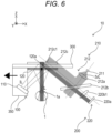
Fig. 6 is a diagram illustrating a state in which an image center is caused to follow a line-of-sight by the image following device including the image following information detecting device according to the first embodiment of the present technology. -
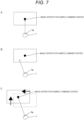
Figs. 7A to 7C are diagrams for explaining an example of a method for causing the image center to follow the line-of-sight by the image following device including the image following information detecting device according to the first embodiment of the present technology. -
Fig. 8 is a cross-sectional view (part 1) for explaining a Configuration Example of an image following information detecting device according to a second embodiment of the present technology. -
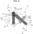
Fig. 9 is a cross-sectional view (part 2) for explaining a Configuration Example of the image following information detecting device according to the second embodiment of the present technology. -
Fig. 10 is a block diagram illustrating a Configuration Example of a control device of an image following device including the image following information detecting device according to the second embodiment of the present technology. -
Fig. 11 is a flowchart for explaining an operation example of the image following device including the image following information detecting device according to the second embodiment of the present technology. -
Fig. 12 is a flowchart for explaining an operation example of an image following device including an image following information detecting device according to a third embodiment of the present technology. -
Figs. 13A and 13B are cross-sectional views of a diffractive optical element for explaining Configuration Examples 1 and 2 of an image following device including an image following information detecting device according to a fourth embodiment of the present technology, respectively. -
Figs. 14A and 14B are cross-sectional views of the diffractive optical element for explaining Configuration Examples 1 and 2 of an image following device including an image following information detecting device according to a fifth embodiment of the present technology, respectively. - Hereinafter, preferred embodiments of the present technology will be described in detail with reference to the accompanying drawings. The first, third, fourth, and fifth embodiments are not encompassed by the wording of the claims but are considered as useful for understanding the invention.
- Note that, in the present specification and the drawings, components having substantially the same functional configuration are denoted by the same reference numerals, and redundant description is omitted. The embodiments described below illustrate representative embodiments of the present technology, and the scope of the present technology is not narrowly interpreted by these embodiments. In the present specification, even in a case where it is described that each of an image following information detecting device, an image following device, an image following information detecting method, and an image following method according to the present technology exhibits a plurality of effects, each of the image following information detecting device, the image following device, the image following information detecting method, and the image following method according to the present technology is only required to exhibit at least one effect. The effects described in the present specification are merely examples and are not limited, and other effects may be provided.
- Furthermore, description will be given in the following order.
- 1. Introduction
- 2. Image Following Information Detecting Device according to First Embodiment of Present Technology and Image Following Device including Image Following Information Detecting Device
- 3. Image Following Information Detecting Device according to Second Embodiment of Present Technology and Image Following Device including Image Following Information Detecting Device
- 4. Image Following Information Detecting Device according to Third Embodiment of Present Technology and Image Following Device including Image Following Information Detecting Device
- 5. Image Following Information Detecting Device according to Fourth Embodiment of Present Technology and Image Following Device including Image Following Information Detecting Device
- 6. Image Following Information Detecting Device according to Fifth Embodiment of Present Technology and Image Following Device including Image Following Information Detecting Device
- 7. Modification of Present Technology
- In recent years, in an HMD (head mounted display) in which development competition is intensifying, detection of eyeball information such as line-of-sight detection is used for, for example, foveated rendering and expansion of a viewable region (eye box). The HMD displays, for example, an augmented reality (AR) image for the user.
- An image following
information detecting device 10 according to a first embodiment of the present technology and an image following device including the image followinginformation detecting device 10 will be described using the drawings. - The image following
information detecting device 10 is mounted on, for example, an HMD (head mounted display) which is an example of an image display device mounted on the head of the user. The HMD is also called an eyewear, for example. - That is, the image following
information detecting device 10 is a head mounted type. -
Fig. 1 is a cross-sectional view schematically illustrating a configuration of the image followinginformation detecting device 10 according to the first embodiment. Hereinafter, it is assumed that the image followinginformation detecting device 10 is worn on the head of the user. - As illustrated in
Fig. 1 , image followinginformation detecting device 10 includes animage display system 100 and a line-of-sight detection system 200. - The
image display system 100 includes an imagelight projecting unit 110 and a transmissive reflection member 120 (also called combiner). - The image
light projecting unit 110 projects image light IL (visible light). As an example, the imagelight projecting unit 110 includes a light source unit that emits the image light IL and a projection lens that is arranged on an optical path of the image light IL from the light source unit and projects the image light IL toward thetransmissive reflection member 120. - The image
light projecting unit 110 is provided integrally with thetransmissive reflection member 120. - The
transmissive reflection member 120 reflects a part of the image light IL projected from the imagelight projecting unit 110 toward aneyeball 1 and transmits the other parts. - As an example, the
transmissive reflection member 120 is provided on a surface on theeyeball 1 side of a transmission substrate 300 (for example, a transparent or translucent substrate held by the frame of the HMD) having at least transparency to visible light so as to face theeyeball 1. - As an example, a
bracket 350 that supports the imagelight projecting unit 110 is provided on thetransmission substrate 300 in a cantilevered state. - The
transmissive reflection member 120 is, for example, a reflection type of diffractive optical element, and reflects and diffracts the image light IL, which is visible light, in a specific direction corresponding to the wavelength with high efficiency. Note that thetransmissive reflection member 120 may be, for example, a half mirror, a glass plate, and the like. - In
Fig. 1 , an XYZ three-dimensional orthogonal coordinate system is set in which a direction in which theeyeball 1 and thetransmissive reflection member 120 face each other is a Z-axis direction, and directions orthogonal to each other in an in-plane direction of thetransmissive reflection member 120 are an X-axis direction and a Y-axis direction. Hereinafter, the XYZ three-dimensional orthogonal coordinate system will be appropriately used for description. - The line-of-
sight detection system 200 includes anirradiation system 210 and alight receiving system 220. - The
irradiation system 210 irradiates theeyeball 1 with invisible light IVL (for example, infrared light). - The
irradiation system 210 includes an invisible light source 211 (for example, an infrared light source) and an irradiationoptical system 212 that guides the invisible light IVL (for example, infrared light) from the invisiblelight source 211 to theeyeball 1. - The invisible
light source 211 is, for example, a light source such as a semiconductor laser or a light emitting diode that emits the invisible light IVL (for example, infrared light). - The irradiation
optical system 212 includes acollimating lens 212a, abeam splitter 212b, and a diffractiveoptical element 212c. The collimating lens is also called a coupling lens. - The
collimating lens 212a is arranged on the optical path of the invisible light IVL from the invisiblelight source 211, and substantially collimates the invisible light substantially. - The
beam splitter 212b is arranged on the optical path of the invisible light IVL via thecollimating lens 212a, reflects a part of the invisible light IVL, and transmits the other parts. Thebeam splitter 212b is, for example, a half mirror. - The diffractive
optical element 212c is arranged on the optical path of the invisible light IVL reflected by thebeam splitter 212b, and reflects and diffracts the invisible light toward theeyeball 1. - The diffractive
optical element 212c includes a reflective diffraction portion 212c1 that reflects and diffracts the invisible light IVL from the invisiblelight source 211 toward the eyeball 1 (more specifically, a pupil la). - The reflective diffraction portion 212c1 reflects and diffracts light of a specific wavelength band (invisible light, for example infrared light) in a specific direction according to the wavelength with high efficiency.
- The diffractive
optical element 212c is provided integrally with thetransmissive reflection member 120. - That is, the diffractive
optical element 212c is also integrally provided with the imagelight projecting unit 110. - More specifically, the diffractive
optical element 212c is provided at a position corresponding to thetransmissive reflection member 120 on the surface of thetransmission substrate 300 on the side opposite to theeyeball 1 side. - Note that the diffractive
optical element 212c may be provided integrally (directly) with thetransmissive reflection member 120. - Details of the reflective diffraction portion 212c1 will be described later.
- The
light receiving system 220 receives the invisible light IVL emitted from theirradiation system 210 to theeyeball 1 and reflected by the eyeball 1 (for example, the fundus of the eyeball 1). - The
light receiving system 220 includes alight receiving element 220a and a light receivingoptical system 220b that guides the invisible light IVL emitted from theirradiation system 210 to theeyeball 1 and reflected by theeyeball 1 to thelight receiving element 220a. - The light receiving
optical system 220b includes the diffractiveoptical element 212c that reflects and diffracts the reflected light (invisible light IVL) from theeyeball 1 toward thebeam splitter 212b, and a condensing lens 220b1 that is arranged on an optical path of the invisible light IVL that has passed through thebeam splitter 212b among the invisible light IVL reflected and diffracted by the diffractiveoptical element 212c and condenses the invisible light IVL on thelight receiving element 220a. - That is, the light receiving
optical system 220b shares thebeam splitter 212b and the diffractiveoptical element 212c with the irradiationoptical system 212. - In other words, the optical path of the invisible light IVL from the
beam splitter 212b to the diffractiveoptical element 212c in theirradiation system 210 and the optical path of the invisible light IVL from the diffractiveoptical element 212c to thebeam splitter 212b in thelight receiving system 220 overlap (substantially coincide) with each other. - The
light receiving element 220a has a plurality of light receiving regions. - The plurality of light receiving regions is, for example, four light receiving regions (220a-1 to 220a-4) arranged two-dimensionally. Each light receiving region is, for example, a photodiode (PD). That is, the
light receiving element 220a is, for example, a four-divided photodiode. - Note that the
light receiving element 220a may be an image sensor including a large number of pixels two-dimensionally arranged at a high density, but here, a four-divided photodiode is used as an example of a superior small-divided photodiode in terms of low power consumption and low latency. - The line-of-sight (the orientation of the eyeball) of the user can be detected by the received light amounts of the four
light receiving regions 220a-1 to 220a-4 of thelight receiving element 220a. - Specifically, for example, in
Fig. 2A , the received light amounts of the fourlight receiving regions 220a-1 to 220a-4 are A, B, C, and D, respectively. - Here, as illustrated in
Fig. 2A , for example, in a case where XY coordinates (for example, the X-axis direction is a horizontal direction, and the Y-axis direction is a vertical direction) with the center of thelight receiving element 220a as the origin O are set, when the center of thepupil 1a is at an arbitrary position in the X-axis direction, the total received light amount (A + B + C + D) has the waveform illustrated in the upper diagram ofFig. 2B , and the horizontal signal ((A + C) - (B + D)) has the waveform illustrated in the lower diagram ofFig. 2B . - Even when the center of the
pupil 1a is located at an arbitrary position in the Y-axis direction, the waveform is similar to the waveform illustrated inFig. 2B . Therefore, the position of the center of thepupil 1a, that is, the line-of-sight (the orientation of the eyeball 1) can be detected by acquiring the total received light amount (total light amount), the horizontal signal, and the vertical signal. - Returning to
Fig. 1 , the reflective diffraction portion 212c1 overlaps aportion 120a irradiated with the central portion of the image light IL of thetransmissive reflection member 120 when viewed from the thickness direction (a direction orthogonal to in-plane direction of thetransmissive reflection member 120, Z-axis direction) of thetransmissive reflection member 120. - Here, as an example, the
portion 120a irradiated with the central portion of the image light IL of thetransmissive reflection member 120 coincides with the central portion (hereinafter, also referred to as a "combiner center") of thetransmissive reflection member 120. - In this case, the reflective diffraction portion 212c1 overlaps the combiner center.
- Note that the
portion 120a irradiated with the central portion of the image light IL of thetransmissive reflection member 120 may be slightly deviated from the central portion (combiner center) of thetransmissive reflection member 120. - Moreover, the central portion of the reflective diffraction portion 212c1 preferably overlaps with the
portion 120a (for example, combiner center) of thetransmissive reflection member 120 irradiated with the central portion of the image light IL when viewed from the thickness direction of thetransmissive reflection member 120. - In this case, for example, the received light amounts of the four
light receiving regions 220a-1 to 220a-4 (seeFig. 2A ) of thelight receiving element 220a indicate the deviation of the user's line-of-sight (pupil center) from the combiner center (center of the image displayed by the image light IL; hereinafter, also referred to as "image center"). Conversely, the received light amounts of the fourlight receiving regions 220a-1 to 220a-2 indicate the deviation of the image center from the user's line-of-sight (pupil center). - Moreover, the size of the reflective diffraction portion 212c1 is preferably equal to or smaller than the maximum diameter of the
pupil 1a of theeyeball 1. - In this case, in
Fig. 1 , since thelight receiving system 220 can receive the light reflected from the cornea of theeyeball 1 irradiated from theirradiation system 210, it is possible to accurately obtain the deviation of the image center from the line-of-sight (pupil center). - On the other hand, for example, in a case where the size of the reflective diffraction portion is larger than the maximum diameter of the
pupil 1a, the reflected light from other than the cornea is also detected, and thus, the detection sensitivity of the center of thepupil 1a becomes low. - Furthermore, the size of the reflective diffraction portion 212c1 may be equal to or larger than the minimum diameter of the
pupil 1a. - In general, the diameter of the
pupil 1a is 2 mm to 8 mm. - That is, in general, the maximum diameter of the
pupil 1a is 8 mm, and the minimum diameter of thepupil 1a is 2 mm. - In
Fig. 1 , the invisible light IVL emitted from the invisiblelight source 211 is diffused to a predetermined diffusion angle, and then, is collimated into light having a predetermined beam diameter (a beam diameter sufficiently larger than that of the reflective diffraction portion 212c1) by thecollimating lens 212a. While the beam diameter is maintained, a part of the invisible light IVL is reflected by thebeam splitter 212b and incident into the reflective diffraction portion 212c1. - In this case, for example, even if the image following
information detecting device 10 is slightly deviated with respect to the head of the user, the invisible light IVL from the invisiblelight source 211 is emitted to the reflective diffraction portion 212c1. - The image following device including the image following
information detecting device 10 according to the first embodiment further includes anactuator 400 and acontrol device 500. - The
actuator 400 moves, for example, at least theimage display system 100 and the diffractiveoptical element 212c in a direction parallel to the in-plane direction of the transmissive reflection member 120 (a direction parallel to the XY plane) with respect to the eyeglass frame of the HMD. - Specifically, as an example, the
actuator 400 can independently move theimage display system 100, the diffractiveoptical element 212c, and thetransmission substrate 300 integrally provided in the X-axis direction and the Y-axis direction. Hereinafter, theimage display system 100, the diffractiveoptical element 212c, and thetransmission substrate 300 are also collectively referred to as a "movement target". - Here, as an example, the
transmission substrate 300 is attached to the eyeglass frame of the HMD via theactuator 400. - That is, the movement target is independently movable in the X-axis direction and the Y-axis direction with respect to the eyeglass frame by the
actuator 400. - Examples of the
actuator 400 include a combination of a biaxial linear motor, a biaxial ball screw mechanism, and a motor as a drive source thereof, and a combination of a biaxial rack-and-pinion mechanism and a motor as a drive source thereof. - In the image following device, the
collimating lens 212a of the image followinginformation detecting device 10 collimates the invisible light IVL from the invisiblelight source 211 to have a cross-sectional size corresponding to the expected movement range of the movement target. - Specifically, for example, the cross-sectional size is a size with which the reflective diffraction portion 212c1 can be irradiated with the invisible light IVL from the invisible
light source 211 even if the movement target moves within the expected movement range. - As illustrated in
Fig. 3 , thecontrol device 500 includes amain control unit 500a and adeviation detection unit 500b. Thecontrol device 500 is realized by a hardware configuration including, for example, a CPU, a chip set, and the like. - The
deviation detection unit 500a detects a deviation (a deviation amount and a deviation direction) of the image from the line-of-sight on the basis of the output of thelight receiving element 220a, and sends the detection result to themain control unit 500a. - The
main control unit 500a generates a drive signal (pulse signal) for driving the movement target in the X-axis direction and a drive signal (pulse signal) for driving the movement target in the Y-axis direction on the basis of the deviation (a deviation direction and a deviation amount) of the image center from the line-of-sight, and outputs the drive signals to theactuator 400. Therefore, theactuator 400 is driven on the basis of the deviation of the image center from the line-of-sight. - Hereinafter, the operation of the image following device including the image following
information detecting device 10 according to the first embodiment will be described with reference to the flowchart ofFig. 4 . The flowchart ofFig. 4 is based on a processing algorithm executed by themain control unit 500a of thecontrol device 500. - In the first Step S1, the
main control unit 500a irradiates the combiner (transmissive reflection member 120) with the image light IL. Specifically, themain control unit 500a projects the image light IL from the imagelight projecting unit 110 toward the combiner. Themain control unit 500a executes Step S1, for example, when the power switch of the image following device is turned on by the user. - In the next Step S2, the
main control unit 500a detects the initial position of the center (pupil center) of thepupil 1a. - Specifically, the
main control unit 500a obtains the initial position of the pupil center (for example, XY coordinates of the pupil center inFig. 2A ) by controlling theactuator 400 to sweep the movement target in the X-axis direction and the Y-axis direction, respectively. For example, themain control unit 500a sweeps the movement target in the X-axis direction and the Y-axis direction, and detects the position of the combiner center when the received light amount in each light receiving region inFig. 2 becomes the same as the initial position of the pupil center. - In the state in which the initial position of the pupil center is detected, the deviation of the combiner center from the line-of-sight is 0 (state in which the line-of-sight and the combiner center intersect).
- Therefore, this state (the state illustrated in
Fig. 1 or the state illustrated inFig. 7A ) is set as the initial position of the movement target by theactuator 400. - In the next Step S3, the
main control unit 500a turns on the invisible light source 211 (for example, an infrared light source). At this time, the invisible light IVL emitted from the invisiblelight source 211 is guided to theeyeball 1 by the irradiationoptical system 212. At least a part of the invisible light IVL reflected by theeyeball 1 is guided to thelight receiving element 220a by the light receivingoptical system 220b. - In the next Step S4, the
deviation detection unit 500b detects the deviation of the combiner center from the line-of-sight. Specifically, thedeviation detection unit 500b detects the deviation (deviation direction and deviation amount) on the basis of the received light amounts of the fourlight receiving regions 220a-1 to 220a-4 of thelight receiving element 220a, and sends the deviation to themain control unit 500a. - For example, in
Figs. 5 and7A , the misalignment of the glasses equipped with the image following device occurs, the deviation of the combiner center from the line-of-sight is large, and the image light IL is hardly incident into thepupil 1a. In this case, there is a possibility that the image is lost. - In the next Step S5, the
main control unit 500a integrally moves theimage display system 100, the diffractiveoptical element 212c, and thetransmission substrate 300 on the basis of the deviation of the combiner center from the line-of-sight. Specifically, themain control unit 500a generates a drive signal that preferably becomes 0 so as to minimize the deviation of the image from the line-of-sight, and applies the drive signal to theactuator 400. - For example, as illustrated in
Fig. 6 , by controlling the actuator 400 from the state illustrated inFig. 5 to perform the operation of detecting the pupil center position (line-of-sight) by the line-of-sight detection system 200, it is possible to eliminate the deviation of the combiner center from the line-of-sight. That is, it is possible to eliminate the deviation between the line-of-sight and the image center. - For example, as illustrated in
Fig. 7C , by controlling the actuator 400 from the state illustrated inFig. 7B to perform the operation of detecting the pupil center position, it is possible to eliminate the deviation of the combiner center from the line-of-sight. - In the final Step S6, the
main control unit 500a determines whether or not the process has ended. Specifically, for example, themain control unit 500a determines that the processing is ended when the switch of the image following device is turned off by the user, and determines that the processing is not being performed (continuing) when the switch remains in the on state. When the determination in Step S6 is negative, the process returns to Step S4, and when the determination is positive, the flow ends. - The image following
information detecting device 10 of the first embodiment described above includes: theimage display system 100 including the imagelight projecting unit 110 that projects the image light IL and thetransmissive reflection member 120 that reflects a part of the image light IL projected from the imagelight projecting unit 110 toward theeyeball 1 and transmits the other parts; the line-of-sight detection system 200 including at least one invisiblelight source 211, the diffractiveoptical element 212c that is provided integrally with thetransmissive reflection member 120 and includes the reflective diffraction portion 212c1 that reflects and diffracts the invisible light IVL from the invisiblelight source 211 toward theeyeball 1; and thelight receiving element 220a that receives the invisible light IVL reflected by theeyeball 1 and reflected and diffracted by the reflective diffraction portion 212c1. Moreover, in the image followinginformation detecting device 10, when viewed from the thickness direction (for example, the Z-axis direction) of thetransmissive reflection member 120, theportion 120a irradiated with the central portion of the image light IL of thetransmissive reflection member 120 overlaps with the reflective diffraction portion 212c1. - In this case, the deviation between the center of the image displayed by the central portion of the image light IL and the line-of-sight can be obtained by the output of the
light receiving element 220a. - As a result, according to the image following
information detecting device 10, it is possible to obtain information for causing the central portion of the image to follow the line-of-sight of the user. - Furthermore, according to the image following
information detecting device 10, since the configuration in which the light from the invisiblelight source 211 is reflected and diffracted by the diffractiveoptical element 212c and incident into theeyeball 1 is adopted, for example, it is not necessary to arrange the light source and the light receiving element on the eyeglass frame of the HMD on which the image followinginformation detecting device 10 is mounted, and a wide visual field of the user can be secured. - When viewed from the thickness direction of the
transmissive reflection member 120, theportion 120a of thetransmissive reflection member 120 irradiated with the central portion of the image light IL and the central portion of the reflective diffraction portion 212c1 preferably overlap each other. Therefore, it is possible to more accurately obtain the deviation between the image center and the line-of-sight, and eventually, it is possible to obtain more highly accurate information for causing the image to follow the line-of-sight of the user. - An image following device including the image following
information detecting device 10 of the first embodiment includes anactuator 400 that moves theimage display system 100 and the diffractiveoptical element 212c in a direction parallel to an in-plane direction of thetransmissive reflection member 120, and acontrol device 500 that controls the actuator on the basis of a signal from thelight receiving element 220a of the image followinginformation detecting device 10. This causes the image to follow the line-of-sight of the user. - The
light receiving element 220a has a plurality of (for example, four)light receiving regions 220a-1 to 220a-4 that are two-dimensionally arrayed, and thecontrol device 500 detects a deviation between the center of the image displayed by theimage display system 100 and the line-of-sight that is the orientation of theeyeball 1 based on the signals from the plurality oflight receiving regions 220a-1 to 220a-4, and controls theactuator 400 on the basis of the detection result. Therefore, it is possible to cause the image to follow the line-of-sight of the user with low latency and low power consumption. - According to the image display device (for example, the HMD) including the image following device including the image following
information detecting device 10 of the first embodiment, since the combiner center follows the line-of-sight, the user can always view the image center. That is, the state in which the visibility of the user for the image is good is continuously maintained. - An image following information detecting method for detecting image following information for causing an image to follow a line-of-sight using the image following
information detecting device 10 of the first embodiment includes: a step of displaying an image by theimage display system 100 of the image followinginformation detecting device 10; a step of acquiring a detection result of the line-of-sight detection system 200 as deviation information between the line-of-sight and a central portion of the image; an image light irradiation step of reflecting the image light IL by thetransmissive reflection member 120 and irradiating the image light IL to theeyeball 1; and a line-of-sight detecting step of reflecting and diffracting the invisible light IVL by the reflective diffraction portion 212c1 provided in thetransmissive reflection member 120 to irradiate theeyeball 1 with the invisible light IVL, and reflecting and diffracting the reflected light by the reflective diffraction portion 212c1 to receive the light, thereby detecting a line-of-sight that is an orientation of theeyeball 1. - In this case, the deviation between the center of the image displayed by the central portion of the image light IL and the line-of-sight can be obtained by receiving the reflected light from the
eyeball 1. - As a result, according to the image following information detecting method, it is possible to obtain information for causing the image to follow the line-of-sight of the user.
- An image following method for causing an image to follow a line-of-sight using the image following
information detecting device 10 of the first embodiment includes: a step of displaying an image by theimage display system 100 of the image followinginformation detecting device 10; a step of acquiring a detection result of the line-of-sight detection system 200 as deviation information between the line-of-sight and a central portion of the image; and a moving step of integrally moving at least the imagelight projecting unit 110, thetransmissive reflection member 120, and the diffractiveoptical element 212c on the basis of the deviation information. This causes the image to follow the line-of-sight of the user. - An image following
information detecting device 20 and an image following information detecting device according to a second embodiment of the present technology will be described below with reference toFigs. 8 to 11 . - The pupil diameter of the eyeball changes depending on the luminance of the ambient light and the image light.
- Therefore, the image following
information detecting device 20 according to the second embodiment has a configuration for coping with such a change in the pupil diameter. - Specifically, as illustrated in
Figs. 8 to 10 , in the image followinginformation detecting device 20 according to the second embodiment, the line-of-sight detection system 200 includes a pupildiameter acquisition unit 500c that acquires the pupil diameter of the eyeball 1 (the diameter of thepupil 1a), a plurality of (for example, two) invisible light sources (for example, first and secondinvisible light sources lighting control unit 500d capable of selectively lighting the plurality of invisiblelight sources diameter acquisition unit 500c. - Moreover, as illustrated in
Figs. 8 and9 , in the image followinginformation detecting device 20 according to the second embodiment, the diffractiveoptical element 212d includes a plurality of (for example, two) reflective diffraction portions (for example, first and second reflective diffraction portions 212d1 and 212d2) that are stacked in the thickness direction (Z-axis direction) and have different diffraction wavelengths and sizes. - The first reflective diffraction portion 212d1 sets the emission wavelength of the first
invisible light source 211a as a diffraction wavelength. That is, the first reflective diffraction portion 212d1 diffracts the invisible light IVL1 from the firstinvisible light source 211a in a specific direction with high efficiency. - The second reflective diffraction portion 212d2 sets the emission wavelength of the second invisible
light source 211b as the diffraction wavelength. That is, the second reflective diffraction portion 212d2 diffracts the invisible light IVL2 from the second invisiblelight source 211b in a specific direction with high efficiency. - As an example, the second reflective diffraction portion 212d2 is larger than the first reflective diffraction portion 212d1.
- As an example, the size of each reflective diffraction portion is equal to or smaller than the maximum diameter (for example, 8 mm) of the
pupil 1a. - The
lighting control unit 500d sequentially lights the first and secondinvisible light sources diameter acquisition unit 500c acquires the pupil diameter of theeyeball 1 every time the first and secondinvisible light sources lighting control unit 500d selects an invisible light source to be lit from the plurality of invisiblelight sources diameter acquisition unit 500c. - As illustrated in
Fig. 10 , the pupildiameter acquisition unit 500c includes, as an example, an illuminance sensor 500c1 and a pupil system estimation unit 500c2 that estimates the pupil diameter of theeyeball 1 on the basis of the detection result of the illuminance sensor 500c1. The illuminance sensor 500c1 is provided, for example, on thebracket 350 that supports the imagelight projecting unit 110. - Hereinafter, an operation of the image following device including the image following
information detecting device 20 according to the second embodiment will be described with reference to a flowchart ofFig. 11 . The flowchart ofFig. 11 is based on a processing algorithm executed by themain control unit 500a of a control device 550 (seeFig. 10 ). - In the first Step S11, the
main control unit 500a irradiates the combiner (transmissive reflection member 120) with the image light IL. Specifically, themain control unit 500a projects the image light IL from the imagelight projecting unit 110 toward the combiner. Note that themain control unit 500a executes Step S11, for example, when the power switch of the image following device is turned on by the user. - In the next Step S12, the illuminance sensor 500c1 detects illuminance information around the
eyeball 1. - In the next Step S13, the pupil diameter estimation unit 500c2 estimates the pupil diameter on the basis of the illuminance information detected by the illuminance sensor 500c1. Specifically, for example, the pupil diameter estimation unit 500c2 stores a table representing the correspondence relationship between the pupil diameter and the illuminance in advance in the memory, and the pupil diameter estimation unit 500c2 refers to the table and estimates the pupil diameter corresponding to the detected illuminance information as the pupil diameter at the time of detecting the illuminance information.
- In the next Step S14, the
lighting control unit 500d selects the invisible light source according to the pupil diameter estimated by the pupil diameter estimation unit 500c2. Specifically, in a case where the estimated pupil diameter is equal to or larger than a threshold (for example, 4 mm) (in a case of a dark pupil), thelighting control unit 500d selects the second invisiblelight source 211b that is an invisible light source corresponding to the larger reflective diffraction portion 212d2. On the other hand, in a case where the estimated pupil diameter is less than the threshold (for example, 4 mm) (in the case of the bright pupil), thelighting control unit 500d selects the firstinvisible light source 211a that is the invisible light source corresponding to the smaller reflective diffraction portion 212d1. - In the next Step S15, the
main control unit 500a turns on the invisible light source selected by thelighting control unit 500d to detect the initial position of the pupil center. - Specifically, the
main control unit 500a obtains the initial position of the pupil center by controlling theactuator 400 to sweep the movement target in the X-axis direction and the Y-axis direction respectively as in Step S2 of the first embodiment described above. - For example, in a case where the first
invisible light source 211a is selected, as illustrated inFig. 8 , the invisible light IVL1 emitted from the firstinvisible light source 211a and passing through thecollimating lens 212a and thebeam splitter 212b is diffracted toward theeyeball 1 by the first reflective diffraction portion 212d1. At least a part of the invisible light IVL1 incident on theeyeball 1 is reflected and diffracted by the first reflective diffraction portion 212d1, and is incident into thelight receiving element 220a via thebeam splitter 212b and the condensing lens 220b1. - For example, in a case where the second invisible
light source 211b is selected, as illustrated inFig. 9 , the invisible light IVL2 emitted from the second invisiblelight source 211b and passing through thecollimating lens 212a and thebeam splitter 212b is diffracted toward theeyeball 1 by the second reflective diffraction portion 212d2. At least a part of the invisible light IVL2 incident into theeyeball 1 is reflected and diffracted by the second reflective diffraction portion 212d2, and is incident into thelight receiving element 220a via thebeam splitter 212b and the condensing lens 220b1. - That is, since the
eyeball 1 is irradiated with the invisible light having a size corresponding to the pupil diameter, the detection accuracy of the pupil center position is improved. - In the state in which the initial position of the pupil center is detected, the deviation of the combiner center from the line-of-sight is 0 (state in which the line-of-sight and the combiner center intersect).
- Therefore, this state (the state illustrated in
Fig. 8 ) is set as the initial position of the movement target by theactuator 400. - In the next Step S16, the
deviation detection unit 500b turns on the selected invisible light source to detect the deviation of the combiner center from the line-of-sight. Also in this case, as described above, since the detection accuracy of the pupil center position is improved, the detection accuracy of the deviation is also improved. - Specifically, the
deviation detection unit 500b detects the deviation (deviation direction and deviation amount) on the basis of the received light amounts of the fourlight receiving regions 220a-1 to 220a-4 of thelight receiving element 220a, and sends the deviation to themain control unit 500a. - In the next Step S17, the
main control unit 500a moves the movement target by the actuator on the basis of the detected deviation. - Specifically, the
main control unit 500a generates a drive signal that preferably becomes 0 so as to minimize the deviation of the image from the line-of-sight, and applies the drive signal to theactuator 400. - In the final Step S18, the
main control unit 500a determines whether or not the process has ended. Specifically, for example, themain control unit 500a determines that the processing is ended when the switch of the image following device is turned off by the user, and determines that the processing is not being performed (continuing) when the switch remains in the on state. When the determination in Step S18 is negative, the process returns to Step S12, and when the determination is positive, the flow ends. - According to the image following
information detecting device 20 of the second embodiment described above, since theeyeball 1 is irradiated with the invisible light having a size corresponding to the pupil diameter, it is possible to accurately obtain the deviation of the image center from the line-of-sight. - According to the image following device including the image following
information detecting device 20 according to the second embodiment, the image center can accurately follow the line-of-sight. - Hereinafter, an image following information detecting device according to a third embodiment of the present technology and an image following device including the image following information detecting device will be described.
- The configuration of the image following information detecting device according to the third embodiment is similar to the configuration of the image following information detecting device according to the above-described second embodiment illustrated in
Figs. 8 to 10 except that the pupildiameter acquisition unit 500c and thelighting control unit 500d are not included. - The configuration of the image following device including the image following information detecting device according to the third embodiment is similar to the configuration of the image following device including the image display position adjustment information detecting device according to the above-described second embodiment except that the image following information detecting device does not include the pupil
diameter acquisition unit 500c. - In the image following information detecting device according to the third embodiment, the diffractive
optical element 212d (seeFigs. 8 and9 ) includes the plurality of reflective diffraction portions 212d1 and 212d2 that are stacked in the thickness direction and have different diffraction wavelengths and sizes, the line-of-sight detection system 200 includes the plurality of invisible light sources (for example, the first and secondinvisible light sources image display system 100 and the line-of-sight that is the orientation of theeyeball 1 for each lighting of the plurality of invisiblelight sources - Hereinafter, the operation of the image following device including the image following information detecting device according to the third embodiment will be described with reference to
Fig. 12 . - In the first Step S21, the
main control unit 500a irradiates the combiner (transmissive reflection member 120) with the image light IL. Specifically, themain control unit 500a projects the image light IL from the imagelight projecting unit 110 toward the combiner. Note that themain control unit 500a executes Step S21, for example, when the power switch of the image following device is turned on by the user. - The image light IL is emitted to the combiner.
- In the next Step S22, the
main control unit 500a turns on the firstinvisible light source 211a and obtains first initial position calculation information of the pupil center. Specifically, in a state where the firstinvisible light source 211a is turned on, themain control unit 500a obtains the first initial position calculation information (for example, XY coordinates) of the pupil center by controlling theactuator 400 to sweep the movement target in the X-axis direction and the Y-axis direction respectively as in Step S2 of the first embodiment described above. - In the next Step S23, the
main control unit 500a turns on the second invisiblelight source 211b and detects second initial position calculation information of the pupil center. Specifically, in a state where the second invisiblelight source 211b is turned on, themain control unit 500a obtains the second initial position calculation information (for example, XY coordinates) of the pupil center by controlling theactuator 400 to sweep the movement target in the X-axis direction and the Y-axis direction respectively as in Step S2 of the first embodiment described above. - In the next Step S24, the
main control unit 500a calculates the initial position of the pupil center on the basis of the first and second initial position calculation information. Specifically, for example, themain control unit 500a sets the average value of the X coordinates and the average value of the Y coordinates of the first and second initial position calculation information as the X coordinate and the Y coordinate of the initial position of the pupil center, respectively. - In the next Step S25, the
main control unit 500a coincides with the combiner center with the calculated initial position of the pupil center. Specifically, themain control unit 500a causes theactuator 400 to move the movement target along the XY plane by a difference (difference between X coordinates and difference between Y coordinates) between the XY coordinates of the combiner center at the current point in time and the calculated XY coordinates of the initial position of the pupil center. - In the next Step S26, the
deviation detection unit 500b turns on the firstinvisible light source 211a and obtains first deviation calculation information (for example, deviation information in the X-axis direction and deviation information in the Y-axis direction) of the combiner center from the line-of-sight. - In the next Step S27, the
deviation detection unit 500b turns on the second invisiblelight source 211b and obtains second deviation calculation information (for example, deviation information in the X-axis direction and deviation information in the Y-axis direction) of the combiner center from the line-of-sight. - In the next Step S28, the
deviation detection unit 500b calculates the deviation of the combiner center from the line-of-sight on the basis of the first and second deviation calculation information. Specifically, for example, themain control unit 500a sets the average value in the X-axis direction and the average value in the Y-axis direction of the first and second deviation calculation information as deviations in the X-axis direction and the Y-axis direction of the combiner center from the line-of-sight, respectively. - In the next Step S29, the
main control unit 500a moves the movement target by the actuator on the basis of the calculated deviation. - Specifically, the
main control unit 500a generates a drive signal that preferably becomes 0 so as to minimize the deviation of the image from the line-of-sight, and applies the drive signal to theactuator 400. - In the final Step S30, the
main control unit 500a determines whether or not the process has ended. Specifically, for example, themain control unit 500a determines that the processing is ended when the switch of the image following device is turned off by the user, and determines that the processing is not being performed (continuing) when the switch remains in the on state. When the determination in Step S30 is negative, the process returns to Step S26, and when the determination is positive, the flow ends. - According to the image following information detecting device according to the third embodiment described above, since the
eyeball 1 is irradiated with the invisible light having a size corresponding to the pupil diameter, it is possible to accurately obtain the deviation of the image center from the line-of-sight. - According to the image following device including the image following information detecting device of the third embodiment, the image center can accurately follow the line-of-sight.
- Hereinafter, an image following information detecting device according to a fourth embodiment of the present technology and an image following device including the image following information detecting device will be described.
-
Figs. 13A and 13B are diagrams for explaining Configuration Example 1 and Configuration Example 2 of the image following device including the image following information detecting device according to the fourth embodiment of the present technology, respectively. - Configuration Example 1 illustrated in
Fig. 13A has the same configuration as the image following device including the image following information detecting device of the first embodiment described above except that the configuration of the actuator is different. - Configuration Example 2 illustrated in
Fig. 13B has the same configuration as the image following device including the image following information detecting device of the second or third embodiment described above except that the configuration of the actuator is different. - As illustrated in
Figs. 13A and 13B , the actuators of Configuration Examples 1 and 2 of the image following device according to the fourth embodiment are actuators that move the movement target only in one axis direction, for example, the X-axis direction. Examples of the actuator include a uniaxial linear motor, a combination of a ball screw mechanism and a drive source (for example, a motor), and a combination of a rack-and-pinion and a drive source (for example, a motor). - In Configuration Example 1 of the image following information detecting device according to the fourth embodiment, as illustrated in
Fig. 13A , a reflective diffraction portion 212e1 of a diffractiveoptical element 212e has a vertically long shape (a shape in which the Y-axis direction is a longitudinal direction) in which a direction orthogonal to the moving direction (X-axis direction) of the movement target by the actuator is a longitudinal direction. - In this case, since the reflective diffraction portion 212e1 can cover a certain range in the Y-axis direction, the deviation of the combiner center from the line-of-sight is obtained only by moving the movement target in the X-axis direction, and the actuator can be driven to reduce the deviation.
- In Configuration Example 2 of the image following information detecting device according to the fourth embodiment, as illustrated in
Fig. 13B , the diffractiveoptical element 212f includes a plurality of (for example, two) reflective diffraction portions 212f1 and 212f2 stacked in the Z-axis direction and having different diffraction wavelengths and sizes. - Each of the two reflective diffraction portions 212f1 and 212f2 has a vertically long shape (a shape in which the Y-axis direction is a longitudinal direction) in which a direction orthogonal to a moving direction (X-axis direction) of the movement target by the actuator is a longitudinal direction.
- In this case, since the reflective diffraction portions 212f1 and f2 can cover a certain range in the Y-axis direction, the deviation of the combiner center from the line-of-sight can be obtained only by moving the movement target in the X-axis direction, and the actuator can be driven to reduce the deviation.
- Moreover, in Configuration Example 2, since the reflective diffraction portions having different diffraction wavelengths and sizes are stacked, the same operations and effects as those of the second or third embodiment described above can be obtained.
- Hereinafter, an image following information detecting device according to a fifth embodiment of the present technology and an image following device including the image following information detecting device will be described.
-
Figs. 14A and 14B are diagrams for explaining Configuration Example 1 and Configuration Example 2 of the image following device including the image following information detecting device according to the fifth embodiment of the present technology, respectively. - Configuration Example 1 illustrated in
Fig. 14A has the same configuration as the image following device including the image following information detecting device of the first embodiment described above except that the configuration of the actuator is different. - Configuration Example 2 illustrated in
Fig. 14B has the same configuration as the image following device including the image following information detecting device of the second or third embodiment described above except that the configuration of the actuator is different. - As illustrated in
Figs. 14A and 14B , the actuators of Configuration Examples 1 and 2 of the image following device according to the fifth embodiment are actuators that move the movement target only in one axis direction, for example, the Y-axis direction. Examples of the actuator include a uniaxial linear motor, a combination of a ball screw mechanism and a drive source (for example, a motor), and a combination of a rack-and-pinion and a drive source (for example, a motor). - In Configuration Example 1 of the image following information detecting device according to the fifth embodiment, as illustrated in
Fig. 14A , a reflective diffraction portion 212g1 of a diffractiveoptical element 212g has a horizontally long shape (a shape in which the X-axis direction is a longitudinal direction) in which a direction orthogonal to the moving direction (Y-axis direction) of the movement target by the actuator is a longitudinal direction. - In this case, since the reflective diffraction portion 212g1 can cover a certain range in the X-axis direction, the deviation of the combiner center from the line-of-sight is obtained only by moving the movement target in the Y-axis direction, and the actuator can be driven to reduce the deviation.
- In Configuration Example 2 of the image following information detecting device according to the fourth embodiment, as illustrated in
Fig. 14B , a diffractiveoptical element 212h includes a plurality of (for example, two) reflective diffraction portions 212h1 and 212h2 stacked in the Z-axis direction and having different diffraction wavelengths and sizes. - Each of the two reflective diffraction portions 212h1 and 212h2 has a horizontally long shape (a shape in which the X-axis direction is a longitudinal direction) in which a direction orthogonal to a moving direction (Y-axis direction) of the movement target by the actuator is a longitudinal direction.
- In this case, since the reflective diffraction portions 212h1 and h2 can cover a certain range in the X-axis direction, the deviation of the combiner center from the line-of-sight can be obtained only by moving the movement target in the Y-axis direction, and the actuator can be driven to reduce the deviation.
- Moreover, in Configuration Example 2, since the reflective diffraction portions having different diffraction wavelengths and sizes are stacked, the same operations and effects as those of the second or third embodiment described above can be obtained.
- The configurations of the image following information detecting device of the present technology and the image following device including the image following information detecting device can be changed as appropriate.
- For example, the line-of-
sight detection system 200 may include a polarizing plate arranged on an optical path of invisible light between the invisible light source and the reflective diffraction portion (for example, an optical path of invisible light between thecollimating lens 212a and thebeam splitter 212b). This makes it possible to remove optical noise (for example, Purkinje image) of the invisible light. - For example, the line-of-
sight detection system 200 may include a wavelength selection filter (for example, a band-pass filter) arranged on an optical path of invisible light between the reflective diffraction portion and thelight receiving element 220a (for example, an optical path of invisible light between the condensing lens 220b1 and thelight receiving element 220a). Therefore, for example, the wavelength of invisible light (for example, infrared light) received by thelight receiving element 220a can be selected. - In each of the embodiments described above, the entire image following information detecting device (including, for example, an invisible light source, a collimating lens, a beam splitter, a condensing lens, and a light receiving element) may be integrally moved by the actuator to reduce (including 0) the deviation of the combiner center with respect to the line-of-sight.
- In this case, for example, even if misalignment of the eyeglass frame of the HMD occurs and the deviation of the combiner center with respect to the line-of-sight becomes very large, it is possible to suppress the reflective diffraction portion from deviating from the irradiation range of the invisible light, and thus, it is possible to quickly perform various types of detection.
- In each of the embodiments described above, the positional relationship between the invisible light source and the light receiving element with respect to the
beam splitter 212b may be reversed. - In each of the embodiments described above, the reflective diffraction portion may be irradiated with the image light IL from the image
light projecting unit 110 via thebeam splitter 212b. - In each of the embodiments described above, the diffractive optical element is used as the
transmissive reflection member 120, but the present invention is not limited thereto, and for example, a glass plate, a half mirror, and the like may be used. -
- 1 eyeball
- 1a pupil
- 10, 20 image following information detecting device
- 100 image display system
- 110 image light projecting unit
- 120 transmissive reflection member
- 120a portion irradiated with the central portion of image light
- 200 line-of-sight detection system
- 211, 211a, 211b invisible light source
- 212a collimating lens
- 212b beam splitter
- 212c diffractive optical element
- 212c1 reflective diffraction portion
- 220a light receiving element
- 220a-1 to 220a-4 light receiving region
- 400 actuator
- IL image light
- IVL invisible light
Claims (14)
- An image following information detecting device (10, 20) comprising:an image display system (100) including an image light projecting unit (110) that projects image light, and a transmissive reflection member (120) that reflects a part of the image light projected from the image light projecting unit toward an eyeball (1) and transmits other parts; anda line-of-sight detection system (200) including at least one invisible light source (211, 211a, 211b), a diffractive optical element (212c) provided integrally with the transmissive reflection member and including a reflective diffraction portion (212c1) that reflects and diffracts invisible light from the invisible light source toward the eyeball, and a light receiving element (220a) that receives the invisible light reflected by the eyeball and reflected and diffracted by the reflective diffraction portion, whereina portion irradiated with a central portion of the image light of the transmissive reflection member and the reflective diffraction portion overlap each other when viewed from a thickness direction of the transmissive reflection member;characterized in thatthe diffractive optical element includes a plurality of the reflective diffraction portions stacked in a thickness direction and having different diffraction wavelengths and sizes, andthe line-of-sight detection system includes: a pupil diameter acquisition unit (500c) that acquires a pupil diameter of the eyeball; a plurality of the invisible light sources (211, 211a, 211b) having different emission wavelengths; and a lighting control unit (500d) that can selectively light the plurality of invisible light sources on a basis of an acquisition result in the pupil diameter acquisition unit.
- The image following information detecting device according to claim 1, wherein a portion of the transmissive reflection member irradiated with a central portion of the image light and a central portion of the reflective diffraction portion overlap each other when viewed from a thickness direction of the transmissive reflection member.
- The image following information detecting device according to claim 1, wherein a size of the reflective diffraction portion is equal to or smaller than a maximum diameter of a pupil of the eyeball.
- The image following information detecting device according to claim 3, wherein a maximum diameter of the pupil is 8 mm.
- The image following information detecting device according to claim 1, wherein the image light projecting unit is provided integrally with the transmissive reflection member.
- The image following information detecting device according to claim 1, wherein the light receiving element includes a plurality of light receiving regions.
- The image following information detecting device according to claim 6, wherein the plurality of light receiving regions is four light receiving regions arranged two-dimensionally.
- The image following information detecting device according to claim 1, wherein the pupil diameter acquisition unit includes an illuminance sensor, and obtains the pupil diameter on a basis of a detection result of the illuminance sensor.
- The image following information detecting device according to claim 1, wherein
the line-of-sight detection system includes a plurality of the invisible light sources having different emission wavelengths, and obtains information for calculating a deviation between a center of an image displayed by the image display system and a line-of-sight that is an orientation of the eyeball for each lighting of the plurality of invisible light sources. - The image following information detecting device according to claim 1, further comprising:a beam splitter that is arranged between the reflective diffraction portion and the light receiving element and into which invisible light from the invisible light source is incident, whereinthe beam splitter reflects a part of invisible light from the invisible light source toward the reflective diffraction portion and transmits a part of invisible light from the reflective diffraction portion toward the light receiving element.
- The image following information detecting device according to claim 1, wherein the line-of-sight detection system includes one of i) a collimating lens that collimates invisible light emitted from the invisible light source; ii) a polarizing plate arranged on an optical path of the invisible light between the invisible light source and the reflective diffraction portion or iii) a wavelength selection filter arranged on an optical path of the invisible light between the reflective diffraction portion and the light receiving element.
- An image following device comprising:an image following information detecting device according to claim 1, wherein the image light projecting unit is provided integrally with the transmissive reflection member;an actuator that moves the image display system and the diffractive optical element in a direction parallel to an in-plane direction of the transmissive reflection member; anda control device that controls the actuator on a basis of a signal from a light receiving element of the image following information detecting device.
- The image following device according to claim 12, further comprising: a collimating lens that collimates invisible light from the invisible light source to have a cross-sectional size corresponding to an expected movement range of the image display system and the diffractive optical element.
- The image following device according to claim 12, whereinthe light receiving element includes a plurality of light receiving regions arranged two-dimensionally, andthe control device detects a deviation between a center of an image displayed by the image display system and a line-of-sight which is an orientation of the eyeball on a basis of signals from the plurality of light receiving regions, and controls the actuator on a basis of a detection result.
Applications Claiming Priority (2)
| Application Number | Priority Date | Filing Date | Title |
|---|---|---|---|
| JP2020016944 | 2020-02-04 | ||
| PCT/JP2020/046682 WO2021157204A1 (en) | 2020-02-04 | 2020-12-15 | Video-tracking-information detection device, video tracking device, video-tracking-information detection method, and video tracking method |
Publications (3)
| Publication Number | Publication Date |
|---|---|
| EP4086691A1 EP4086691A1 (en) | 2022-11-09 |
| EP4086691A4 EP4086691A4 (en) | 2023-06-28 |
| EP4086691B1 true EP4086691B1 (en) | 2024-11-27 |
Family
ID=77199926
Family Applications (1)
| Application Number | Title | Priority Date | Filing Date |
|---|---|---|---|
| EP20917961.3A Active EP4086691B1 (en) | 2020-02-04 | 2020-12-15 | Video-tracking-information detection device |
Country Status (4)
| Country | Link |
|---|---|
| US (1) | US12554142B2 (en) |
| EP (1) | EP4086691B1 (en) |
| KR (1) | KR20220130138A (en) |
| WO (1) | WO2021157204A1 (en) |
Family Cites Families (13)
| Publication number | Priority date | Publication date | Assignee | Title |
|---|---|---|---|---|
| AT409042B (en) * | 1999-11-24 | 2002-05-27 | Life Optics Handel Und Vertrie | sehhilfe |
| JP4682470B2 (en) | 2001-07-16 | 2011-05-11 | 株式会社デンソー | Scan type display device |
| US8817379B2 (en) * | 2011-07-12 | 2014-08-26 | Google Inc. | Whole image scanning mirror display system |
| US9606354B2 (en) | 2014-07-17 | 2017-03-28 | Google Inc. | Heads-up display with integrated display and imaging system |
| US9377623B2 (en) * | 2014-08-11 | 2016-06-28 | Microsoft Technology Licensing, Llc | Waveguide eye tracking employing volume Bragg grating |
| EP3198192A1 (en) | 2014-09-26 | 2017-08-02 | Milan Momcilo Popovich | Holographic waveguide opticaltracker |
| IL241033B (en) * | 2015-09-02 | 2021-12-01 | Eyeway Vision Ltd | Eye projection device and method |
| KR102821244B1 (en) * | 2017-03-21 | 2025-06-13 | 매직 립, 인코포레이티드 | Method and system for tracking eye movement in conjunction with a light scanning projector |
| JP7033329B2 (en) | 2017-04-04 | 2022-03-10 | 国立大学法人福井大学 | Video generator and video generation method |
| WO2018190007A1 (en) | 2017-04-13 | 2018-10-18 | ソニー株式会社 | Image display device |
| US10394034B2 (en) | 2017-08-15 | 2019-08-27 | Microsoft Technology Licensing, Llc | Eye-tracking with MEMS scanning and optical relay |
| CN107783297A (en) * | 2017-11-22 | 2018-03-09 | 深圳创维新世界科技有限公司 | Nearly eye display device |
| US11861063B2 (en) * | 2019-02-05 | 2024-01-02 | Samsung Electronics Co., Ltd. | Eye-tracking device and display apparatus including the same |
-
2020
- 2020-12-15 WO PCT/JP2020/046682 patent/WO2021157204A1/en not_active Ceased
- 2020-12-15 US US17/795,625 patent/US12554142B2/en active Active
- 2020-12-15 KR KR1020227025675A patent/KR20220130138A/en active Pending
- 2020-12-15 EP EP20917961.3A patent/EP4086691B1/en active Active
Also Published As
| Publication number | Publication date |
|---|---|
| EP4086691A4 (en) | 2023-06-28 |
| KR20220130138A (en) | 2022-09-26 |
| EP4086691A1 (en) | 2022-11-09 |
| WO2021157204A1 (en) | 2021-08-12 |
| US12554142B2 (en) | 2026-02-17 |
| US20230095993A1 (en) | 2023-03-30 |
Similar Documents
| Publication | Publication Date | Title |
|---|---|---|
| US12099197B2 (en) | Head-mounted display eyeball tracker integrated system | |
| CN106164745B (en) | Head mounted display and low conspicuity pupil illuminator | |
| US8360583B2 (en) | Image display device with exit pupil moving for tracking viewer's pupil | |
| US20180157908A1 (en) | Gaze-tracking system and method of tracking user's gaze | |
| US11947128B2 (en) | Digital illumination assisted gaze tracking for augmented reality near to eye displays | |
| TW201712371A (en) | Projection device for data eyeglasses, data eyeglasses, and process to operate a projection device for data eyeglasses enabling a user to have projected image on their data eyeglasses | |
| RU2700373C1 (en) | Eye tracking system | |
| US11487126B2 (en) | Method for calibrating a projection device for a head-mounted display, and projection device for a head-mounted display for carrying out the method | |
| US20240142771A1 (en) | Optical device, retinal projection display, and head-mounted display | |
| US20250123482A1 (en) | Eyeball information detection apparatus, display apparatus, eyeball information detection method, and display method | |
| KR102946693B1 (en) | Optical system and method for gaze tracking based on redirecting light from the eye using an optical array associated with a light-guiding optical element | |
| WO2020255562A1 (en) | Image display device and display device | |
| EP4086691B1 (en) | Video-tracking-information detection device | |
| US20230288986A1 (en) | Method for a pupil detection and/or pupil tracking, optical system and smart glasses | |
| US12277266B2 (en) | Line-of-sight detection device, display device, and method for sensing eyeball | |
| US20230393324A1 (en) | Image display device and image display method | |
| JP3623482B2 (en) | Video display device | |
| US20250251598A1 (en) | Image display device | |
| US20230288713A1 (en) | Display Device | |
| JP2009506948A (en) | Vehicle display system having partially transparent elements and method for operating a vehicle display system | |
| JPH07128613A (en) | Head-mounted video display | |
| WO2024202682A1 (en) | Display device and display method | |
| JPWO2019138972A1 (en) | Display method and display device | |
| JPH06121255A (en) | Head mount type display device |
Legal Events
| Date | Code | Title | Description |
|---|---|---|---|
| STAA | Information on the status of an ep patent application or granted ep patent |
Free format text: STATUS: THE INTERNATIONAL PUBLICATION HAS BEEN MADE |
|
| PUAI | Public reference made under article 153(3) epc to a published international application that has entered the european phase |
Free format text: ORIGINAL CODE: 0009012 |
|
| STAA | Information on the status of an ep patent application or granted ep patent |
Free format text: STATUS: REQUEST FOR EXAMINATION WAS MADE |
|
| 17P | Request for examination filed |
Effective date: 20220714 |
|
| AK | Designated contracting states |
Kind code of ref document: A1 Designated state(s): AL AT BE BG CH CY CZ DE DK EE ES FI FR GB GR HR HU IE IS IT LI LT LU LV MC MK MT NL NO PL PT RO RS SE SI SK SM TR |
|
| DAV | Request for validation of the european patent (deleted) | ||
| DAX | Request for extension of the european patent (deleted) | ||
| REG | Reference to a national code |
Ref legal event code: R079 Free format text: PREVIOUS MAIN CLASS: G02B0027020000 Ref country code: DE Ref legal event code: R079 Ref document number: 602020042300 Country of ref document: DE Free format text: PREVIOUS MAIN CLASS: G02B0027020000 Ipc: G02B0027010000 |
|
| A4 | Supplementary search report drawn up and despatched |
Effective date: 20230525 |
|
| RIC1 | Information provided on ipc code assigned before grant |
Ipc: G09G 3/02 20060101ALI20230519BHEP Ipc: G02B 27/00 20060101ALI20230519BHEP Ipc: G02B 5/32 20060101ALI20230519BHEP Ipc: H04N 13/344 20180101ALI20230519BHEP Ipc: H04N 5/64 20060101ALI20230519BHEP Ipc: G09G 5/38 20060101ALI20230519BHEP Ipc: G09G 5/00 20060101ALI20230519BHEP Ipc: A61B 3/113 20060101ALI20230519BHEP Ipc: G02B 27/01 20060101AFI20230519BHEP |
|
| GRAP | Despatch of communication of intention to grant a patent |
Free format text: ORIGINAL CODE: EPIDOSNIGR1 |
|
| STAA | Information on the status of an ep patent application or granted ep patent |
Free format text: STATUS: GRANT OF PATENT IS INTENDED |
|
| INTG | Intention to grant announced |
Effective date: 20240701 |
|
| GRAS | Grant fee paid |
Free format text: ORIGINAL CODE: EPIDOSNIGR3 |
|
| GRAA | (expected) grant |
Free format text: ORIGINAL CODE: 0009210 |
|
| STAA | Information on the status of an ep patent application or granted ep patent |
Free format text: STATUS: THE PATENT HAS BEEN GRANTED |
|
| P01 | Opt-out of the competence of the unified patent court (upc) registered |
Free format text: CASE NUMBER: APP_55972/2024 Effective date: 20241011 |
|
| AK | Designated contracting states |
Kind code of ref document: B1 Designated state(s): AL AT BE BG CH CY CZ DE DK EE ES FI FR GB GR HR HU IE IS IT LI LT LU LV MC MK MT NL NO PL PT RO RS SE SI SK SM TR |
|
| REG | Reference to a national code |
Ref country code: GB Ref legal event code: FG4D |
|
| REG | Reference to a national code |
Ref country code: CH Ref legal event code: EP |
|
| REG | Reference to a national code |
Ref country code: DE Ref legal event code: R096 Ref document number: 602020042300 Country of ref document: DE |
|
| REG | Reference to a national code |
Ref country code: IE Ref legal event code: FG4D |
|
| REG | Reference to a national code |
Ref country code: LT Ref legal event code: MG9D |
|
| REG | Reference to a national code |
Ref country code: NL Ref legal event code: MP Effective date: 20241127 |
|
| PG25 | Lapsed in a contracting state [announced via postgrant information from national office to epo] |
Ref country code: HR Free format text: LAPSE BECAUSE OF FAILURE TO SUBMIT A TRANSLATION OF THE DESCRIPTION OR TO PAY THE FEE WITHIN THE PRESCRIBED TIME-LIMIT Effective date: 20241127 Ref country code: PT Free format text: LAPSE BECAUSE OF FAILURE TO SUBMIT A TRANSLATION OF THE DESCRIPTION OR TO PAY THE FEE WITHIN THE PRESCRIBED TIME-LIMIT Effective date: 20250327 Ref country code: IS Free format text: LAPSE BECAUSE OF FAILURE TO SUBMIT A TRANSLATION OF THE DESCRIPTION OR TO PAY THE FEE WITHIN THE PRESCRIBED TIME-LIMIT Effective date: 20250327 |
|
| PG25 | Lapsed in a contracting state [announced via postgrant information from national office to epo] |
Ref country code: FI Free format text: LAPSE BECAUSE OF FAILURE TO SUBMIT A TRANSLATION OF THE DESCRIPTION OR TO PAY THE FEE WITHIN THE PRESCRIBED TIME-LIMIT Effective date: 20241127 Ref country code: NL Free format text: LAPSE BECAUSE OF FAILURE TO SUBMIT A TRANSLATION OF THE DESCRIPTION OR TO PAY THE FEE WITHIN THE PRESCRIBED TIME-LIMIT Effective date: 20241127 |
|
| REG | Reference to a national code |
Ref country code: AT Ref legal event code: MK05 Ref document number: 1746235 Country of ref document: AT Kind code of ref document: T Effective date: 20241127 |
|
| PG25 | Lapsed in a contracting state [announced via postgrant information from national office to epo] |
Ref country code: BG Free format text: LAPSE BECAUSE OF FAILURE TO SUBMIT A TRANSLATION OF THE DESCRIPTION OR TO PAY THE FEE WITHIN THE PRESCRIBED TIME-LIMIT Effective date: 20241127 |
|
| PG25 | Lapsed in a contracting state [announced via postgrant information from national office to epo] |
Ref country code: ES Free format text: LAPSE BECAUSE OF FAILURE TO SUBMIT A TRANSLATION OF THE DESCRIPTION OR TO PAY THE FEE WITHIN THE PRESCRIBED TIME-LIMIT Effective date: 20241127 |
|
| PG25 | Lapsed in a contracting state [announced via postgrant information from national office to epo] |
Ref country code: NO Free format text: LAPSE BECAUSE OF FAILURE TO SUBMIT A TRANSLATION OF THE DESCRIPTION OR TO PAY THE FEE WITHIN THE PRESCRIBED TIME-LIMIT Effective date: 20250227 |
|
| PG25 | Lapsed in a contracting state [announced via postgrant information from national office to epo] |
Ref country code: LV Free format text: LAPSE BECAUSE OF FAILURE TO SUBMIT A TRANSLATION OF THE DESCRIPTION OR TO PAY THE FEE WITHIN THE PRESCRIBED TIME-LIMIT Effective date: 20241127 Ref country code: AT Free format text: LAPSE BECAUSE OF FAILURE TO SUBMIT A TRANSLATION OF THE DESCRIPTION OR TO PAY THE FEE WITHIN THE PRESCRIBED TIME-LIMIT Effective date: 20241127 Ref country code: GR Free format text: LAPSE BECAUSE OF FAILURE TO SUBMIT A TRANSLATION OF THE DESCRIPTION OR TO PAY THE FEE WITHIN THE PRESCRIBED TIME-LIMIT Effective date: 20250228 |
|
| PG25 | Lapsed in a contracting state [announced via postgrant information from national office to epo] |
Ref country code: PL Free format text: LAPSE BECAUSE OF FAILURE TO SUBMIT A TRANSLATION OF THE DESCRIPTION OR TO PAY THE FEE WITHIN THE PRESCRIBED TIME-LIMIT Effective date: 20241127 |
|
| PG25 | Lapsed in a contracting state [announced via postgrant information from national office to epo] |
Ref country code: RS Free format text: LAPSE BECAUSE OF FAILURE TO SUBMIT A TRANSLATION OF THE DESCRIPTION OR TO PAY THE FEE WITHIN THE PRESCRIBED TIME-LIMIT Effective date: 20250227 |
|
| PG25 | Lapsed in a contracting state [announced via postgrant information from national office to epo] |
Ref country code: SM Free format text: LAPSE BECAUSE OF FAILURE TO SUBMIT A TRANSLATION OF THE DESCRIPTION OR TO PAY THE FEE WITHIN THE PRESCRIBED TIME-LIMIT Effective date: 20241127 |
|
| PG25 | Lapsed in a contracting state [announced via postgrant information from national office to epo] |
Ref country code: DK Free format text: LAPSE BECAUSE OF FAILURE TO SUBMIT A TRANSLATION OF THE DESCRIPTION OR TO PAY THE FEE WITHIN THE PRESCRIBED TIME-LIMIT Effective date: 20241127 |
|
| PG25 | Lapsed in a contracting state [announced via postgrant information from national office to epo] |
Ref country code: EE Free format text: LAPSE BECAUSE OF FAILURE TO SUBMIT A TRANSLATION OF THE DESCRIPTION OR TO PAY THE FEE WITHIN THE PRESCRIBED TIME-LIMIT Effective date: 20241127 |
|
| PG25 | Lapsed in a contracting state [announced via postgrant information from national office to epo] |
Ref country code: RO Free format text: LAPSE BECAUSE OF FAILURE TO SUBMIT A TRANSLATION OF THE DESCRIPTION OR TO PAY THE FEE WITHIN THE PRESCRIBED TIME-LIMIT Effective date: 20241127 |
|
| PG25 | Lapsed in a contracting state [announced via postgrant information from national office to epo] |
Ref country code: SK Free format text: LAPSE BECAUSE OF FAILURE TO SUBMIT A TRANSLATION OF THE DESCRIPTION OR TO PAY THE FEE WITHIN THE PRESCRIBED TIME-LIMIT Effective date: 20241127 |
|
| PG25 | Lapsed in a contracting state [announced via postgrant information from national office to epo] |
Ref country code: CZ Free format text: LAPSE BECAUSE OF FAILURE TO SUBMIT A TRANSLATION OF THE DESCRIPTION OR TO PAY THE FEE WITHIN THE PRESCRIBED TIME-LIMIT Effective date: 20241127 |
|
| PG25 | Lapsed in a contracting state [announced via postgrant information from national office to epo] |
Ref country code: IT Free format text: LAPSE BECAUSE OF FAILURE TO SUBMIT A TRANSLATION OF THE DESCRIPTION OR TO PAY THE FEE WITHIN THE PRESCRIBED TIME-LIMIT Effective date: 20241127 |
|
| REG | Reference to a national code |
Ref country code: CH Ref legal event code: PL |
|
| PG25 | Lapsed in a contracting state [announced via postgrant information from national office to epo] |
Ref country code: LU Free format text: LAPSE BECAUSE OF NON-PAYMENT OF DUE FEES Effective date: 20241215 |
|
| REG | Reference to a national code |
Ref country code: DE Ref legal event code: R097 Ref document number: 602020042300 Country of ref document: DE |
|
| PG25 | Lapsed in a contracting state [announced via postgrant information from national office to epo] |
Ref country code: SE Free format text: LAPSE BECAUSE OF FAILURE TO SUBMIT A TRANSLATION OF THE DESCRIPTION OR TO PAY THE FEE WITHIN THE PRESCRIBED TIME-LIMIT Effective date: 20241127 |
|
| PG25 | Lapsed in a contracting state [announced via postgrant information from national office to epo] |
Ref country code: MC Free format text: LAPSE BECAUSE OF FAILURE TO SUBMIT A TRANSLATION OF THE DESCRIPTION OR TO PAY THE FEE WITHIN THE PRESCRIBED TIME-LIMIT Effective date: 20241127 |
|
| PLBE | No opposition filed within time limit |
Free format text: ORIGINAL CODE: 0009261 |
|
| STAA | Information on the status of an ep patent application or granted ep patent |
Free format text: STATUS: NO OPPOSITION FILED WITHIN TIME LIMIT |
|
| REG | Reference to a national code |
Ref country code: BE Ref legal event code: MM Effective date: 20241231 |
|
| PG25 | Lapsed in a contracting state [announced via postgrant information from national office to epo] |
Ref country code: BE Free format text: LAPSE BECAUSE OF NON-PAYMENT OF DUE FEES Effective date: 20241231 |
|
| PG25 | Lapsed in a contracting state [announced via postgrant information from national office to epo] |
Ref country code: FR Free format text: LAPSE BECAUSE OF NON-PAYMENT OF DUE FEES Effective date: 20250127 |
|
| PG25 | Lapsed in a contracting state [announced via postgrant information from national office to epo] |
Ref country code: CH Free format text: LAPSE BECAUSE OF NON-PAYMENT OF DUE FEES Effective date: 20241231 |
|
| PG25 | Lapsed in a contracting state [announced via postgrant information from national office to epo] |
Ref country code: IE Free format text: LAPSE BECAUSE OF NON-PAYMENT OF DUE FEES Effective date: 20241215 |
|
| GBPC | Gb: european patent ceased through non-payment of renewal fee |
Effective date: 20250227 |
|
| 26N | No opposition filed |
Effective date: 20250828 |
|
| PGFP | Annual fee paid to national office [announced via postgrant information from national office to epo] |
Ref country code: DE Payment date: 20251126 Year of fee payment: 6 |
|
| PG25 | Lapsed in a contracting state [announced via postgrant information from national office to epo] |
Ref country code: GB Free format text: LAPSE BECAUSE OF NON-PAYMENT OF DUE FEES Effective date: 20250227 |