EP4060237B1 - Mounting a ceramic component to a non-ceramic component in a gas turbine engine - Google Patents
Mounting a ceramic component to a non-ceramic component in a gas turbine engine Download PDFInfo
- Publication number
- EP4060237B1 EP4060237B1 EP22172384.4A EP22172384A EP4060237B1 EP 4060237 B1 EP4060237 B1 EP 4060237B1 EP 22172384 A EP22172384 A EP 22172384A EP 4060237 B1 EP4060237 B1 EP 4060237B1
- Authority
- EP
- European Patent Office
- Prior art keywords
- combustor
- mount
- groove
- heat shield
- projection
- Prior art date
- Legal status (The legal status is an assumption and is not a legal conclusion. Google has not performed a legal analysis and makes no representation as to the accuracy of the status listed.)
- Active
Links
Images




Classifications
-
- F—MECHANICAL ENGINEERING; LIGHTING; HEATING; WEAPONS; BLASTING
- F23—COMBUSTION APPARATUS; COMBUSTION PROCESSES
- F23R—GENERATING COMBUSTION PRODUCTS OF HIGH PRESSURE OR HIGH VELOCITY, e.g. GAS-TURBINE COMBUSTION CHAMBERS
- F23R3/00—Continuous combustion chambers using liquid or gaseous fuel
- F23R3/42—Continuous combustion chambers using liquid or gaseous fuel characterised by the arrangement or form of the flame tubes or combustion chambers
- F23R3/60—Support structures; Attaching or mounting means
-
- F—MECHANICAL ENGINEERING; LIGHTING; HEATING; WEAPONS; BLASTING
- F23—COMBUSTION APPARATUS; COMBUSTION PROCESSES
- F23R—GENERATING COMBUSTION PRODUCTS OF HIGH PRESSURE OR HIGH VELOCITY, e.g. GAS-TURBINE COMBUSTION CHAMBERS
- F23R3/00—Continuous combustion chambers using liquid or gaseous fuel
- F23R3/002—Wall structures
-
- F—MECHANICAL ENGINEERING; LIGHTING; HEATING; WEAPONS; BLASTING
- F23—COMBUSTION APPARATUS; COMBUSTION PROCESSES
- F23R—GENERATING COMBUSTION PRODUCTS OF HIGH PRESSURE OR HIGH VELOCITY, e.g. GAS-TURBINE COMBUSTION CHAMBERS
- F23R3/00—Continuous combustion chambers using liquid or gaseous fuel
- F23R3/007—Continuous combustion chambers using liquid or gaseous fuel constructed mainly of ceramic components
-
- F—MECHANICAL ENGINEERING; LIGHTING; HEATING; WEAPONS; BLASTING
- F05—INDEXING SCHEMES RELATING TO ENGINES OR PUMPS IN VARIOUS SUBCLASSES OF CLASSES F01-F04
- F05D—INDEXING SCHEME FOR ASPECTS RELATING TO NON-POSITIVE-DISPLACEMENT MACHINES OR ENGINES, GAS-TURBINES OR JET-PROPULSION PLANTS
- F05D2240/00—Components
- F05D2240/35—Combustors or associated equipment
-
- F—MECHANICAL ENGINEERING; LIGHTING; HEATING; WEAPONS; BLASTING
- F23—COMBUSTION APPARATUS; COMBUSTION PROCESSES
- F23R—GENERATING COMBUSTION PRODUCTS OF HIGH PRESSURE OR HIGH VELOCITY, e.g. GAS-TURBINE COMBUSTION CHAMBERS
- F23R2900/00—Special features of, or arrangements for continuous combustion chambers; Combustion processes therefor
- F23R2900/00017—Assembling combustion chamber liners or subparts
-
- Y—GENERAL TAGGING OF NEW TECHNOLOGICAL DEVELOPMENTS; GENERAL TAGGING OF CROSS-SECTIONAL TECHNOLOGIES SPANNING OVER SEVERAL SECTIONS OF THE IPC; TECHNICAL SUBJECTS COVERED BY FORMER USPC CROSS-REFERENCE ART COLLECTIONS [XRACs] AND DIGESTS
- Y02—TECHNOLOGIES OR APPLICATIONS FOR MITIGATION OR ADAPTATION AGAINST CLIMATE CHANGE
- Y02T—CLIMATE CHANGE MITIGATION TECHNOLOGIES RELATED TO TRANSPORTATION
- Y02T50/00—Aeronautics or air transport
- Y02T50/60—Efficient propulsion technologies, e.g. for aircraft
Definitions
- first and the second connections 36A and 36B may accommodate (e.g., thermally induced) movement between the turbine engine component 34 and components connected thereto.
- the spring / resilient compliance of the protrusions 76 may enable differential thermal expansion between the protrusions 76 as well as the support structure 32 and the turbine engine component 34; thus, radial movement.
- the interlocking joint connections 36A and 36B may enable axial (e.g., thermally induced) movement between the components 32 and/or 76 and the turbine engine component 34; e.g., the protrusions 76 may slide within the grooves 50.
- the combustor hood 112 may also be an annular wall connected to the inner and the outer combustor walls 106 and 108.
- the combustor hood 112 has an arcuate (e.g., semi-circular) sectional geometry, which provides an annular plenum 114 axially between the hood 112 and the bulkhead 110.
- the outer combustor wall 108 is connected to the bulkhead 110 and the hood 112 at an outer j oint.
- the hood 112, the support shell 116, the first component mount 68A (e.g., its mount base) and the bulkhead 110 are arranged (e.g., sequentially) in a first stack 120.
- Each of the fasteners 78A may project through this first stack 120 to thereby secure the components 112, 116B, 68A and 110 together.
- the components 112, 116B, 68A and 110 may be arranged in other orders within the first stack 120.
- the combustor 104 is configured to direct cooling air to a portion of the projection 66A within the groove 50A.
- the support shell 116A, 116B may include one or more apertures 124 (e.g., impingement apertures), which are fluidly coupled with one or more passages 126 and 128 around the protrusions 76A.
- One or more additional passages 130 may also direct cooling air between the bulkhead 110 and the first component mount 68A.
- These passages 126, 128 and/or 130 may be formed by one or more grooves in the first component mount 68A and/or one or more grooves in the adjacent components 110, 118A and 118B.
- the combustor wall 106, 108 may be configured with one or more quench or dilution apertures 138.
- Each of these quench or dilution apertures 138 may be formed at least in part by a tubular body 140 (e.g., a grommet) and extends radially through the turbine engine component 34 (e.g., the heat shield 118) and the support structure 32 (e.g., the support shell 116).
- the first portion 98 and the second portion 100 are circumferentially and axially aligned relative to the centerline 38 (e.g., centerline shown in FIGS. 1 and 7 ).
- the first portion 98 and the second portion 100 are circumferentially aligned, but may be axially offset, relative to the centerline 38 (e.g., centerline shown in FIGS. 1 and 7 ).
- the corrugated body may be a segmented body may up from a plurality of protrusions; e.g., circumferentially adjacent corrugations 141 may be (e.g., circumferentially) separated by a respective slit to provide the protrusions.
Landscapes
- Engineering & Computer Science (AREA)
- Chemical & Material Sciences (AREA)
- Combustion & Propulsion (AREA)
- Mechanical Engineering (AREA)
- General Engineering & Computer Science (AREA)
- Ceramic Engineering (AREA)
- Turbine Rotor Nozzle Sealing (AREA)
Description
- This disclosure relates generally to a gas turbine engine and, more particularly, to an assembly for mounting a ceramic component to a non-ceramic component within a gas turbine engine.
- Certain developments in gas turbine engine technology have led to increased internal gas temperatures within the engine. To accommodate these increased internal gas temperatures, gas turbine engine components such as gas path liners may be air cooled and/or constructed from high temperature materials. For example, a gas path liner may be constructed from a ceramic matrix composite (CMC) material. A typical CMC material, however, may have very different properties (e.g., a coefficient of thermal expansion) than other typical gas turbine engine materials such as metal. Special compliant connections therefore are provided in order to mount a CMC component to a metal component to allow, for example, thermally induced movement between those components. While various such compliant connections are known in the art, there is still room for improvement. There is a need in the art therefore for improved mounts between a ceramic (e.g., CMC) component and a non-ceramic (e.g., metal) component.
EP3115690A1 discloses an arrangement of the prior art. - According to the invention, a combustor with a centerline is provided according to
claim 1. - A groove end surface may extend radially between the groove first side surface and the groove second side surface.
- The combustor may be configured to direct cooling air to a portion of the projection within the groove.
- The projection may be configured from or otherwise include metal.
- A heat shield mount may be included, which heat shield mount may include the projection. The heat shield mount may be configured as a monolithic full hoop body.
- A heat shield mount may be included, which heat shield mount may include the projection and a mount base. The projection may project axially out from the mount base and into the groove.
- A combustor bulkhead and a combustor hood may be included. The combustor hood, the combustor bulkhead, the heat shield mount and the support structure may be arranged together in a stack and connected together by a fastener that projects radially through the stack.
- A heat shield mount may be included, which heat shield mount may include the projection and a mount base. The heat shield mount may be configured with a mount groove extending radially between the projection and the mount base. The support structure and the heat shield may project axially into the mount groove.
- The heat shield mount may be attached to the support structure by a fastener extending radially through a slot formed in the mount base.
- The heat shield may extend axially along the centerline between an upstream end and a downstream end. The interlocking joint connection may be located at the upstream end or the downstream end.
- The heat shield may include a plurality of heat shield panels arranged circumferentially about the centerline. The groove may be configured with a first of the plurality of the heat shield panels.
- The support structure may include a shell extending circumferentially about and axially along the centerline. A cooling cavity may be formed by and may extend radially between the shell and the heat shield.
- The heat shield may be configured with a plurality of apertures extending radially through the heat shield.
- A locating feature may be included and configured to circumferentially and/or axially locate the heat shield relative to the support structure. The locating feature may be configured as or otherwise include a tubular body that forms a quench aperture.
- The present disclosure may include one or more of the features mentioned herein alone or in any combination.
- The foregoing features and the operation of the invention will become more apparent in light of the following description and the accompanying drawings.
-
-
FIG. 1 is a partial side sectional illustration of an assembly for a gas turbine engine. -
FIG. 2 is a cross-sectional illustration of a support structure for the turbine engine assembly taken along line 2-2 inFIG. 1 . -
FIG. 3 is a cross-sectional illustration of a component for the turbine engine assembly taken along line 3-3 inFIG. 1 . -
FIG. 4 is a partial side sectional illustration of the turbine engine component. -
FIG. 5 is a partial first end view illustration of the turbine engine component. -
FIG. 6 is a partial second end view illustration of the turbine engine component. -
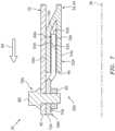
FIG. 7 is a partial side sectional illustration of a first connection between the turbine engine component and the support structure. -
FIG. 8 is a partial side view illustration of a first component mount. -
FIG. 9 is a partial side sectional illustration of the first component mount taken along line 9-9 inFIG. 8 . -
FIG. 10 is a partial side sectional illustration of a second connection between the turbine engine component and the support structure. -
FIG. 11A is a partial first end view illustration of a second component mount. -
FIG. 11B is a partial perspective illustration of the second component mount. -
FIG. 12 is a partial side sectional illustration of the second component mount taken along line 12-12 inFIG. 11A . -
FIGS. 13-15 are partial side sectional illustrations of connections between the turbine engine component and the support structure with alternative component mounts. -
FIG. 16 is a partial side sectional illustration of a combustor. -
FIG. 17 is a partial side sectional illustration of an outer joint between components of the combustor. -
FIGS. 18 and19 are partial side sectional illustrations of inner joints between components of the combustor. -
FIGS. 20 and21 are partial side sectional illustration of joints between components of the combustor with cooling air passages. -
FIG. 22 is a partial side sectional illustration of a combustor wall of the combustor. -
FIG. 23 is a perspective illustration of a circumferential segment of another component mount. -
FIG. 24 is a sectional illustration of the component mount ofFIG. 23 , taken along line 24-24 inFIG. 23 , arranged within a groove of a turbine engine component. -
FIG. 25 is a side cutaway illustration of a geared turbine engine. -
FIG. 1 illustrates anassembly 30 for a gas turbine engine. Thisturbine engine assembly 30 includes astationary support structure 32 and aturbine engine component 34 such as, but not limited to, a gas path liner (e.g., a combustor heat shield) or any other component exposed to hot gases within the gas turbine engine. Theturbine engine component 34 is connected (e.g., mounted) to thesupport structure 32 by one or more connections; e.g., a first (e.g., forward / upstream)connection 36A and/or a second (e.g., aft / downstream)connection 36B. - The
support structure 32 ofFIG. 2 extends circumferentially about (e.g., completely around) acenterline 38 of theassembly 30; e.g., a rotational axis of the gas turbine engine. Thissupport structure 32 may be configured as a monolithic full hoop body. Referring toFIG. 1 , thesupport structure 32 extends axially along thecenterline 38 between a first (e.g., forward / upstream)end 40 and a second (e.g., aft / downstream)end 42. Thesupport structure 32 may be constructed from or otherwise include a non-ceramic material such as, but not limited to, metal. Examples of such metal include, but are not limited to, cobalt alloys, such as Haynes 25 and Haynes 188, and nickel alloys such as Inconel 625. - The
turbine engine component 34 ofFIG. 3 extends circumferentially about (e.g., completely around) thecenterline 38. Thisturbine engine component 34 may be configured as a monolithic full hoop body. Alternatively, as shown inFIG. 3 , theturbine engine component 34 may be configured from a plurality of turbineengine component segments 44; e.g., heat shield / liner panels. Each of thesecomponent segments 44 may be configured as a monolithic (e.g., arcuate) body. Thecomponent segments 44 ofFIG. 3 are arranged circumferentially about thecenterline 38 in an annular array. Each of thecomponent segments 44 in this array is disposed circumferentially between two respective circumferentially adjacent neighboringcomponent segments 44. Referring toFIG. 1 , theturbine engine component 34 and each of itscomponent segments 44 extend axially along thecenterline 38 between a first (e.g., forward / upstream)end 46 and a second (e.g., aft / downstream)end 48. Theturbine engine component 34 and each of itscomponent segments 44 may be constructed from or otherwise include a ceramic material such as, but not limited to, a ceramic matrix composite (CMC) material. Examples of such a CMC material include, but are not limited to, SiC/SiC, or oxide/oxide. - Referring to
FIG. 4 , each of thecomponent segments 44 is configured with one or more grooves. Thecomponent segment 44 ofFIG. 4 , for example, includes a first (e.g., forward / upstream)groove 50A located at (e.g., on, adjacent or proximate) theforward end 46. The component segment ofFIG. 4 further includes a second (e.g., aft / downstream)groove 50B located at thesecond end 48. - The
first groove 50A ofFIG. 4 is formed by a first Y-flange 52A at thefirst end 46. This first Y-flange 52A includes a firstinner flange 54A and a firstouter flange 56A, where eachflange base 58 of therespective component segment 44 to thefirst end 46. Thefirst groove 50A extends axially into the first Y-flange 52A from thefirst end 46 to a firstgroove end surface 60A. Thefirst groove 50A extends radially between a first innergroove side surface 62A and a first outergroove side surface 64A, where the firstgroove end surface 60A extends radially between interior edges of the side surfaces 62A and 64A. The first innergroove side surface 62A may be carried / defined by the firstinner flange 54A. The first outergroove side surface 64A may be carried / defined by the firstouter flange 56A. Thefirst groove 50A ofFIG. 5 extends circumferentially about thecenterline 38 and through thecomponent segment 44 and its first Y-flange 52A. However, thefirst groove 50A may extend circumferentially within or partially into thecomponent segment 44 and its first Y-flange 52A. - The
second groove 50B ofFIG. 4 is formed by a second Y-flange 52B at thesecond end 48. This second Y-flange 52B includes a secondinner flange 54B and a secondouter flange 56B, where eachflange component segment base 58 to thesecond end 48. Thesecond groove 50B extends axially into the second Y-flange 52B from thesecond end 48 to a secondgroove end surface 60B. Thesecond groove 50B extends radially between a second innergroove side surface 62B and a second outergroove side surface 64B, where the secondgroove end surface 60B extends radially between interior edges of the side surfaces 62B and 64B. The second innergroove side surface 62B may be carried / defined by the secondinner flange 54B. The second outergroove side surface 64B may be carried / defined by the secondouter flange 56B. Thesecond groove 50B ofFIG. 6 extends circumferentially about thecenterline 38 and through thecomponent segment 44 and its second Y-flange 52B. However, thesecond groove 50B may extend circumferentially within or partially into thecomponent segment 44 and its second Y-flange 52B. - Referring to
FIG. 7 , thefirst connection 36A is configured to secure at least a first (e.g., forward / upstream) end portion of theturbine engine component 34 with thesupport structure 32. More particularly, thefirst connection 36A ofFIG. 7 is configured to secure first end portion(s) of one or more or each of thecomponent segments 44 with thesupport structure 32. - The
first connection 36A may be configured as an interlocking joint connection such as, but not limited to, a rim seal connection, a keyed connection, a tongue-and-groove connection, etc. Thefirst connection 36A ofFIG. 7 , for example, includes afirst projection 66A (e.g., a rim or a flange) and one or more or each of thefirst grooves 50A. - Referring to
FIG. 8 , thefirst projection 66A is configured as part of a first component (e.g., heat shield)mount 68A. Thisfirst component mount 68A ofFIG. 8 extends circumferentially about (e.g., completely around) thecenterline 38. Thefirst component mount 68A may be configured as a monolithic full hoop body. However, thefirst component mount 68A may be configured from a plurality of (e.g., arcuate) first component mount segments arranged, for example, in an annular array. - The
first component mount 68A may be constructed from or otherwise include metal. Examples of such metal include, but are not limited to, a high temperature cobalt alloy such as, but not limited to, Haynes 25 and Haynes 188. - The
first component mount 68A ofFIG. 8 includes thefirst projection 66A and afirst mount base 70A. Thisfirst mount base 70A extends circumferentially about (e.g., completely around) thecenterline 38. Referring toFIG. 9 , thefirst mount base 70A extends axially along the centerline 38 from a first (e.g., forward / upstream)end 72A of thefirst component mount 68A to thefirst projection 66A. Thefirst projection 66A extends axially along the centerline 38 from thefirst mount base 70A to a second (e.g., aft / downstream)end 74A of thefirst component mount 68A. - The
first projection 66A includes a plurality offirst protrusions 76A; e.g., fingers. Referring toFIG. 8 , thefirst protrusions 76A are arranged circumferentially about thecenterline 38 in, for example, an annular array. Referring toFIG. 9 , each of thefirst protrusions 76A projects axially along thecenterline 38 out from, for example, thefirst mount base 70A to thesecond end 74A of thefirst component mount 68A. Eachfirst protrusion 76A is circumferentially separated from a circumferentially adjacent neighboringfirst protrusion 76A by a first slot. Each of thefirst protrusions 76A may be configured as a compliant / spring finger. With such a configuration, each of thefirst protrusions 76A is adapted to flex / bend radially up-and-down independent of the otherfirst protrusions 76A. - Referring to
FIG. 7 , thefirst component mount 68A is located at thefirst end 40 of thesupport structure 32. Thefirst mount base 70A is connected (e.g., mounted) to thesupport structure 32 by one ormore fasteners 78A; e.g., sets ofbolts 80 and nuts 82. Thefirst mount base 70A, of course, may also or alternatively be connected to thesupport structure 32 by one or more other fastening and/or bonding techniques. Still alternatively, thefirst mount base 70A may be configured as an integral portion of thesupport structure 32. - The
turbine engine component 34 and, more particularly, each of itscomponent segments 44 may be translated axially along thecenterline 38 in a forward direction (see arrow 84) to mate each of the first Y-flanges 52A with thefirst projection 66A. More particular, thefirst projection 66A is arranged with the first Y-flanges 52A such that each of thefirst protrusions 76A projects axially along thecenterline 38 into a respective one of thefirst grooves 50A. Thus, eachfirst groove 50A receives one or more of thefirst protrusions 76A. Thefirst protrusions 76A and thefirst grooves 50A thereby form the first (e.g., interlocking joint)connection 36A between theturbine engine component 34 and thesupport structure 32. - Referring to
FIG. 10 , thesecond connection 36B is configured to secure at least a second (e.g., aft / downstream) end portion of theturbine engine component 34 with thesupport structure 32. More particularly, thesecond connection 36B ofFIG. 10 is configured to secure second end portion(s) of one or more or each of thecomponent segments 44 with thesupport structure 32. - The
second connection 36B may be configured as an interlocking joint connection such as, but not limited to, a rim seal connection, a keyed connection, a tongue-and-groove connection, etc. Thesecond connection 36B ofFIG. 10 , for example, includes asecond projection 66B (e.g., a rim or a flange) and one or more or each of thesecond grooves 50A. - Referring to
FIGS. 11A and11B , thesecond projection 66B is configured as part of a second component (e.g., heat shield)mount 68B. Thissecond component mount 68B ofFIGS. 11A and11B extends circumferentially about (e.g., completely around) thecenterline 38. Thesecond component mount 68B may be configured as a monolithic full hoop body. However, in other examples, thesecond component mount 68B may be configured from a plurality of (e.g., arcuate) second component mount segments arranged, for example, in an annular array. - The
second component mount 68B may be constructed from or otherwise include metal. Examples of such metal include, but are not limited to, a high temperature cobalt alloy such as, but not limited to, Haynes 25 and Haynes 188. - The
second component mount 68B ofFIG. 11A includes thesecond projection 66B and asecond mount base 70B. Thissecond mount base 70B extends circumferentially about (e.g., completely around) thecenterline 38. Referring toFIG. 12 , thesecond mount base 70B extends axially along the centerline 38 from or about a first (e.g., forward / upstream)end 72B of thesecond component mount 68B to thesecond projection 66B. Thesecond projection 66B extends axially along the centerline 38 from thesecond mount base 70B to or about thefirst end 72B of thesecond component mount 68B. Thesecond projection 66B thereby axially overlaps (e.g., is bent / folded back relative to) thesecond mount base 70B. Where theturbine engine component 34 is arranged radially within the support structure 32 (e.g., seeFIG. 10 ), thesecond projection 66B is radially within (e.g., circumscribed by) thesecond mount base 70B. Where thesupport structure 32 is arranged radially within theturbine engine component 34, thesecond mount base 70B is radially within (e.g., circumscribed by) thesecond projection 66B. Thesecond projection 66B is connected to thesecond mount base 70B at a second (e.g., aft / downstream)end 74B of thesecond component mount 68B. For example, a radially inward (or outward) turnedportion 86 of thesecond mount base 70B may extend radially inwards (or outwards) to a radially outward (or inward) turnedportion 88 of thesecond projection 66B. With this configuration, thesecond component mount 68B is configured with a (e.g., annular)mount groove 90 formed by and radially between thesecond mount base 70B and thesecond projection 66B. - The
second projection 66B includes a plurality ofsecond protrusions 76B; e.g., fingers. Referring toFIG. 11A , thesecond protrusions 76B are arranged circumferentially about thecenterline 38 in, for example, an annular array. Referring toFIG. 12 , each of thesecond protrusions 76B projects out from, for example, thesecond mount base 70B and axially along thecenterline 38 to or about thefirst end 72B of thesecond component mount 68B. Referring toFIG. 11A , eachsecond protrusion 76B is circumferentially separated from a circumferentially adjacent neighboringsecond protrusion 76B by a second slot. Each of thesecond protrusions 76B may be configured as a compliant / spring finger. With such a configuration, each of thesecond protrusions 76B is adapted to flex / bend radially up-and-down independent of the othersecond protrusions 76B. - Referring to
FIG. 10 , thesecond component mount 68B may be translated along thecenterline 38 in the forward direction (see the arrow 84) to mate thesupport structure 32 and theturbine engine component 34 and itscomponent segments 44 with themount groove 90. More particularly, a second end portion of thesupport structure 32 and one or more or each of the secondouter flanges 56B is arranged within (e.g., projects axially into) themount groove 90. With this arrangement, thesecond projection 66B is arranged with the second Y-flanges 52B such that each of thesecond protrusions 76B projects axially along thecenterline 38 into a respective one of thesecond grooves 50A. Thus, eachsecond groove 50B receives one or more of thesecond protrusions 76B. Thesecond protrusions 76B and thesecond grooves 50B thereby form the second (e.g., interlocking joint)connection 36B between theturbine engine component 34 and thesupport structure 32. Furthermore, thesecond mount base 70B is connected (e.g., mounted) to thesupport structure 32 by one ormore fasteners 78B; e.g., sets ofstuds 92 and nuts 94. In particular, each of thefasteners 78B (e.g., each stud 92) may be located within arespective slot 96 in thesecond mount base 70B as thesecond component mount 68B is axially translated. Thesecond component mount 68B is thereby located at and secured to thesecond end 42 of thesupport structure 32. Thesecond mount base 70B, of course, may also or alternatively be connected to thesupport structure 32 by one or more other fastening and/or bonding techniques. - Referring to
FIGS. 13-15 , in some examples, eachprotrusion respective groove protrusion 76 ofFIGS. 13-15 , for example, includes afirst portion 98 and asecond portion 100. Thefirst portion 98 radially engages and may be radially biased against one of the side surfaces 62 or 64 (e.g.,surface 62 inFIGS. 13-15 ). Thefirst portion 98 may also be radially disengaged from (e.g., spaced from) the other side surface 64 or 62 (e.g.,surface 64 inFIGS. 13-15 ). Thesecond portion 100 radially engages and may be radially biased against the other one of the side surfaces 64 or 62 (e.g.,surface 64 inFIGS. 13-15 ). Thesecond portion 100 may also be radially disengaged from (e.g., spaced from) the other side surface 62 or 64 (e.g.,surface 62 inFIGS. 13-15 ). In the specific example ofFIG. 13 , the first portion 98 (e.g., axially) overlaps / is bent back over and radially displaced from thesecond portion 100. In the specific example ofFIGS. 14 and 15 , thefirst portion 98 is (e.g., axially) next to and radially displaced from thesecond portion 100. Thus, thesecond portion 100 is (e.g., axially) between thefirst portion 98 and thegroove end surface FIG. 15 , theprotrusion 76 further includes athird portion 102 that radially engages one of the side surfaces 62 or 64 (e.g.,surface 62 inFIGS. 13-15 ). Thethird portion 102 may also be radially disengaged from (e.g., spaced from) the other side surface 64 or 62 (e.g.,surface 64 inFIGS. 13-15 ). In this example, thesecond portion 100 is (e.g., axially) next to and between as well as radially displaced from both thefirst portion 98 and thethird portion 102. Thus, thethird portion 102 is (e.g., axially) between thesecond portion 100 and thegroove end surface 60. - By engaging both the side surfaces 62 and 64 with the
projection turbine engine component 34 during operation. Furthermore, while the projection 66 is radially biased against both side surfaces 62 and 64, the projection 66 in general may be configured to bias theturbine engine component 34 radially against thesupport structure 32. This may prevent rattling of theturbine engine component 34 against thesupport structure 32. The radial bias may also maintain a seal, for example, between theturbine engine component 34 and thesupport structure 32. - In addition to the foregoing, the first and the
second connections turbine engine component 34 and components connected thereto. The spring / resilient compliance of theprotrusions 76, for example, may enable differential thermal expansion between theprotrusions 76 as well as thesupport structure 32 and theturbine engine component 34; thus, radial movement. The interlockingjoint connections components 32 and/or 76 and theturbine engine component 34; e.g., theprotrusions 76 may slide within thegrooves 50. -
FIG. 16 illustrates acombustor 104 for the gas turbine engine. Thiscombustor 104 includes aninner combustor wall 106, anouter combustor wall 108, acombustor bulkhead 110 and acombustor hood 112. Thecombustor 104 may be configured as an annular combustor. Each of the inner andouter combustor walls centerline 38. Thecombustor bulkhead 110 may be an annular wall that extends circumferentially around thecenterline 38 and radially from theinner combustor wall 106 to theouter combustor wall 108. Thecombustor hood 112 may also be an annular wall connected to the inner and theouter combustor walls FIG. 16 , thecombustor hood 112 has an arcuate (e.g., semi-circular) sectional geometry, which provides anannular plenum 114 axially between thehood 112 and thebulkhead 110. - Each of the
combustor walls tubular support shell tubular heat shield FIG. 1 , the support shell 116 may be configured as or otherwise include thesupport structure 32 and the heat shield 118 may be configured as or otherwise include theturbine engine component 34. - Referring to
FIG. 17 , theouter combustor wall 108 is connected to thebulkhead 110 and thehood 112 at an outer j oint. At this outer j oint, thehood 112, the support shell 116, thefirst component mount 68A (e.g., its mount base) and thebulkhead 110 are arranged (e.g., sequentially) in afirst stack 120. Each of thefasteners 78A may project through thisfirst stack 120 to thereby secure thecomponents components first stack 120. - Referring to
FIG. 18 , theinner combustor wall 106 is connected to thebulkhead 110 and thehood 112 at an inner j oint. At this inner j oint, thehood 112, thebulkhead 110, thefirst component mount 68A (e.g., its mount base) and thesupport shell 116A are arranged (e.g., sequentially) in asecond stack 122. Each of thefasteners 78A may project through thissecond stack 122 to thereby secure thecomponents components second stack 122. For example, referring toFIG. 19 , thebulkhead 110, thefirst component mount 68A, thesupport shell 116A and thehood 112 may be arranged (e.g., sequentially) in thesecond stack 122 at the inner joint. - In some examples, referring to
FIGS. 20 and21 , thecombustor 104 is configured to direct cooling air to a portion of theprojection 66A within thegroove 50A. For example, thesupport shell more passages protrusions 76A. One or moreadditional passages 130 may also direct cooling air between thebulkhead 110 and thefirst component mount 68A. Thesepassages first component mount 68A and/or one or more grooves in theadjacent components - In some embodiments, referring to
FIG. 22 , the turbine engine component 34 (e.g., the heat shield 118) may be configured with one ormore apertures 132; e.g., effusion apertures. The support structure 32 (e.g., the support shell 116) may also or alternatively be configured with one ormore apertures 134; e.g., impingement apertures. Acooling cavity 136 formed by and extends radially between theturbine engine component 34 and thesupport structure 32 may fluidly couple one or more of theapertures 132 with one or more of theapertures 134. - In some examples, the
combustor wall dilution apertures 138. Each of these quench ordilution apertures 138 may be formed at least in part by a tubular body 140 (e.g., a grommet) and extends radially through the turbine engine component 34 (e.g., the heat shield 118) and the support structure 32 (e.g., the support shell 116). - In some examples, one or more or each
tubular body 140 may be configured as a locating feature. Each locating feature may laterally (e.g., circumferentially and/or axially) locate the turbine engine component 34 (e.g., the heat shield 118) relative to the support structure 32 (e.g., the support shell 116). For example, by projecting into a respective aperture in theturbine engine component 34, the tubular body 140 (e.g., locating feature) ofFIG. 22 may function as a stop that prevents (or substantially reduces) lateral movement of theturbine engine component 34 relative to thesupport structure 32 at a lateral point of thetubular body 140. By contrast, theconnections FIG. 1 ) may enable lateral shifting between thecomponents components - As described above with reference to
FIGS. 13-15 , at least thefirst portion 98 is engaged with one of the side surfaces 62 or 64 (e.g.,surface 62 inFIGS. 13-15 ) and may be disengaged with the other one of the side surfaces 64 or 62 (e.g.,surface 64 inFIGS. 13-15 ). Similarly, thesecond portion 100 is engaged with one of the side surfaces 64 or 62 (e.g.,surface 64 inFIGS. 13-15 ) and may be disengaged with the other one of the side surfaces 62 or 64 (e.g.,surface 62 inFIGS. 13-15 ). In the example ofFIG. 13 , thefirst portion 98 and thesecond portion 100 are circumferentially and axially aligned relative to the centerline 38 (e.g., centerline shown inFIGS. 1 and7 ). In the example ofFIG. 14 , thefirst portion 98 and thesecond portion 100 are circumferentially aligned, but may be axially offset, relative to the centerline 38 (e.g., centerline shown inFIGS. 1 and7 ). - Referring to
FIGS. 23 and 24 , in embodiments of the invention, thefirst portion 98 and thesecond portion 100 are axially aligned, but may be circumferentially offset, relative to thecenterline 38. - In the invention, as shown in
FIGS. 23 and 24 , the projection 66 is configured as a (e.g., annular or arcuate) corrugated body; e.g., an unsegmented corrugated body.Corrugations 141 of the projection 66 may be formed integral with one another as shown inFIGS. 23 and 24 ; e.g., eachcorrugation 141 is continuous with (e.g., not discrete from) adjacent corrugation(s) 141. Thecorrugations 141 are provided instead of theprotrusions 76 described above. Of course, in still other embodiments, the corrugated body may be a segmented body may up from a plurality of protrusions; e.g., circumferentiallyadjacent corrugations 141 may be (e.g., circumferentially) separated by a respective slit to provide the protrusions. -
FIG. 25 is a side cutaway illustration of a gearedturbine engine 142 with which theturbine engine assembly 30 / thecombustor 104 may be included. Thisturbine engine 142 extends along thecenterline 38 between anupstream airflow inlet 144 and adownstream airflow exhaust 146. Theturbine engine 142 includes afan section 148, acompressor section 149, acombustor section 150 and aturbine section 151. Thecompressor section 149 includes a low pressure compressor (LPC)section 149A and a high pressure compressor (HPC)section 149B. Theturbine section 151 includes a high pressure turbine (HPT)section 151A and a low pressure turbine (LPT)section 151B. - The engine sections 148-151B are arranged sequentially along the
centerline 38 within anengine housing 152. Thishousing 152 includes an inner case 154 (e.g., a core case) and an outer case 156 (e.g., a fan case). Theinner case 154 may house one or more of theengine sections 149A-151B; e.g., an engine core. Theouter case 156 may house at least thefan section 148. - Each of the
engine sections - The
fan rotor 158 is connected to agear train 164, for example, through afan shaft 166. Thegear train 164 and theLPC rotor 159 are connected to and driven by theLPT rotor 162 through alow speed shaft 167. TheHPC rotor 160 is connected to and driven by theHPT rotor 161 through ahigh speed shaft 168. The shafts 166-168 are rotatably supported by a plurality ofbearings 170; e.g., rolling element and/or thrust bearings. Each of thesebearings 170 is connected to theengine housing 152 by at least one stationary structure such as, for example, an annular support strut. - During operation, air enters the
turbine engine 142 through theairflow inlet 144. This air is directed through thefan section 148 and into acore gas path 172 and abypass gas path 174. Thecore gas path 172 extends sequentially through theengine sections 149A-151B. The air within thecore gas path 172 may be referred to as "core air". Thebypass gas path 174 extends through a bypass duct, which bypasses the engine core. The air within thebypass gas path 174 may be referred to as "bypass air". - The core air is compressed by the
compressor rotors combustion chamber 176 of thecombustor 104 in thecombustor section 150. Fuel is injected into thecombustion chamber 176 and mixed with the compressed core air to provide a fuel-air mixture. This fuel air mixture is ignited and combustion products thereof flow through and sequentially cause theturbine rotors turbine rotors compressor rotors turbine rotor 162 also drives rotation of thefan rotor 158, which propels bypass air through and out of thebypass gas path 174. The propulsion of the bypass air may account for a majority of thrust generated by theturbine engine 142, e.g., more than seventy-five percent (75%) of engine thrust. Theturbine engine 142 of the present disclosure, however, is not limited to the foregoing exemplary thrust ratio. - The
turbine engine assembly 30 /combustor 104 may be included in various turbine engines other than the one described above. Theturbine engine assembly 30 /combustor 104, for example, may be included in a geared turbine engine where a gear train connects one or more shafts to one or more rotors in a fan section, a compressor section and/or any other engine section. Alternatively, theturbine engine assembly 30 /combustor 104 may be included in a turbine engine configured without a gear train. Theturbine engine assembly 30 /combustor 104 may be included in a geared or non-geared turbine engine configured with a single spool, with two spools (e.g., seeFIG. 25 ), or with more than two spools. The turbine engine may be configured as a turbofan engine, a turbojet engine, a propfan engine, a pusher fan engine or any other type of turbine engine. The present disclosure therefore is not limited to any particular types or configurations of turbine engines. - While various embodiments of the present disclosure have been described, it will be apparent to those of ordinary skill in the art that many more embodiments and implementations are possible within the scope of the disclosure. For example, the present disclosure as described herein includes several aspects and embodiments that include particular features. Although these features may be described individually, it is within the scope of the present disclosure that some or all of these features may be combined with any one of the aspects and remain within the scope of the disclosure. Accordingly, the present disclosure is not to be restricted except in light of the attached claims.
Claims (15)
- A combustor with a centerline, comprising:a support structure (32, 116); anda heat shield (34, 118) extending circumferentially about and axially along the centerline (38), the heat shield (34, 118) comprising ceramic material, and the heat shield (34, 118) mounted to the support structure (32, 116) by an interlocking joint connection (36);the interlocking joint connection (36) comprising a projection (66) and a groove (50), theprojection (66) configured with the support structure (32, 116) and configured as a corrugated bodyprojecting axially along the centerline into the groove (50), and the groove (50) formed in the heat shield (34, 118) radially between a groove first side surface (62) and a groove second side surface (64); andthe corrugated body engaging and biased radially against the groove first side surface (62) and the groove second side surface (64).
- The combustor of claim 1, wherein a groove end surface (60) extends radially between the groove first side surface (62) and the groove second side surface (64).
- The combustor of any preceding claim, wherein the combustor is configured to direct cooling air to a portion of the projection (66) within the groove (50).
- The combustor of any preceding claim, wherein the projection (66) comprises metal.
- The combustor of any preceding claim, further comprising a heat shield mount (68A) including the projection (66), the heat shield mount (68A) configured as a monolithic full hoop body.
- The combustor of any preceding claim, further comprising a or the heat shield mount (68A) including the projection (66) and a mount base (70A), the projection (66) projecting axially out from the mount base (70A) and into the groove (50).
- The combustor of claim 5 or 6, further comprising:a combustor bulkhead (110); anda combustor hood (112);the combustor hood (112), the combustor bulkhead (110), the heat shield mount (68A) and the support structure (32, 116) arranged together in a stack (120) and connected together by a fastener (78A) that projects radially through the stack (120).
- The combustor of any preceding claim, further comprising:a second heat shield mount (68B) including a second projection (66B) and a second mount base (70B);the second heat shield mount (68B) configured with a mount groove (90) extending radially between the second projection (66B) and the second mount base (70B); andthe support structure (32, 116) and the heat shield (34, 118) projecting axially into the mount groove (90),
- The combustor of claim 8, wherein the second heat shield mount (68B) is attached to the support structure (32, 116) by a fastener (78B) extending radially through a slot (96) formed in the second mount base (70B).
- The combustor of any preceding claim, wherein:the heat shield (34,118) extends axially along the centerline (38) between an upstream end (46) and a downstream end (48); andthe interlocking joint connection (36) is located at the upstream end (46) or the downstream end (48).
- The combustor of any preceding claim, further comprising a locating feature (140) configured to circumferentially and/or axially locate the heat shield (34, 118) relative to the support structure (32, 116), the locating feature comprising a tubular body that forms a quench aperture.
- The combustor of any preceding claim, wherein the corrugated body is an unsegmented corrugated body.
- The combustor of any of claims 1-11, wherein the corrugated body is a segmented body.
- The combustor of claim 13, wherein the corrugated body comprises a plurality of protrusions.
- The combustor of claim 14, wherein the corrugated body comprises a plurality of circumferentially adjacent corrugations (141) separated by a respective plurality of slits to provide the protrusions.
Applications Claiming Priority (2)
| Application Number | Priority Date | Filing Date | Title |
|---|---|---|---|
| US16/591,841 US11215367B2 (en) | 2019-10-03 | 2019-10-03 | Mounting a ceramic component to a non-ceramic component in a gas turbine engine |
| EP20199867.1A EP3800399B1 (en) | 2019-10-03 | 2020-10-02 | Mounting a ceramic component to a non-ceramic component in a gas turbine engine |
Related Parent Applications (2)
| Application Number | Title | Priority Date | Filing Date |
|---|---|---|---|
| EP20199867.1A Division EP3800399B1 (en) | 2019-10-03 | 2020-10-02 | Mounting a ceramic component to a non-ceramic component in a gas turbine engine |
| EP20199867.1A Division-Into EP3800399B1 (en) | 2019-10-03 | 2020-10-02 | Mounting a ceramic component to a non-ceramic component in a gas turbine engine |
Publications (2)
| Publication Number | Publication Date |
|---|---|
| EP4060237A1 EP4060237A1 (en) | 2022-09-21 |
| EP4060237B1 true EP4060237B1 (en) | 2023-11-29 |
Family
ID=72744661
Family Applications (2)
| Application Number | Title | Priority Date | Filing Date |
|---|---|---|---|
| EP22172384.4A Active EP4060237B1 (en) | 2019-10-03 | 2020-10-02 | Mounting a ceramic component to a non-ceramic component in a gas turbine engine |
| EP20199867.1A Active EP3800399B1 (en) | 2019-10-03 | 2020-10-02 | Mounting a ceramic component to a non-ceramic component in a gas turbine engine |
Family Applications After (1)
| Application Number | Title | Priority Date | Filing Date |
|---|---|---|---|
| EP20199867.1A Active EP3800399B1 (en) | 2019-10-03 | 2020-10-02 | Mounting a ceramic component to a non-ceramic component in a gas turbine engine |
Country Status (2)
| Country | Link |
|---|---|
| US (2) | US11215367B2 (en) |
| EP (2) | EP4060237B1 (en) |
Families Citing this family (16)
| Publication number | Priority date | Publication date | Assignee | Title |
|---|---|---|---|---|
| US11402100B2 (en) * | 2018-11-15 | 2022-08-02 | Pratt & Whitney Canada Corp. | Ring assembly for double-skin combustor liner |
| DE102019204544A1 (en) * | 2019-04-01 | 2020-10-01 | Siemens Aktiengesellschaft | Tube combustion chamber system and gas turbine system with such a tube combustion chamber system |
| US11215367B2 (en) * | 2019-10-03 | 2022-01-04 | Raytheon Technologies Corporation | Mounting a ceramic component to a non-ceramic component in a gas turbine engine |
| DE102020203017A1 (en) * | 2020-03-10 | 2021-09-16 | Siemens Aktiengesellschaft | Combustion chamber with ceramic heat shield and seal |
| CN116792200A (en) | 2022-03-16 | 2023-09-22 | 通用电气公司 | Combustion liner assembly |
| CN117091161A (en) | 2022-05-13 | 2023-11-21 | 通用电气公司 | Burner Liner Hollow Plate Design and Construction |
| CN117091159A (en) | 2022-05-13 | 2023-11-21 | 通用电气公司 | burner lining |
| CN117091158B (en) | 2022-05-13 | 2026-03-06 | 通用电气公司 | Combustion chamber mesh structure |
| CN117091157A (en) | 2022-05-13 | 2023-11-21 | 通用电气公司 | Plate hanger construction for durable combustion chamber lining |
| CN117091162B (en) | 2022-05-13 | 2026-03-27 | 通用电气公司 | Burner with dilution hole structure |
| US11788491B1 (en) | 2022-07-13 | 2023-10-17 | General Electric Company | Systems and methods for attachment of materials having different thermal expansion coefficients |
| US12398660B2 (en) | 2022-07-13 | 2025-08-26 | General Electric Company | Systems and methods for attachment of materials having different thermal expansion coefficients |
| GB202308411D0 (en) * | 2023-06-06 | 2023-07-19 | Rolls Royce Plc | Combustor assembly for a gas turbine engine |
| US12313261B1 (en) | 2024-04-05 | 2025-05-27 | Rtx Corporation | Combustor liner panels |
| US12270545B1 (en) | 2024-05-20 | 2025-04-08 | Rtx Corporation | T-head bolts or hollow flanged bushing with one thread or grooved end in a multi-liner arrangement |
| US12474052B1 (en) | 2024-05-20 | 2025-11-18 | Rtx Corporation | Dovetail features on panel rails or impingement sheet to hold panels |
Family Cites Families (19)
| Publication number | Priority date | Publication date | Assignee | Title |
|---|---|---|---|---|
| US4380896A (en) | 1980-09-22 | 1983-04-26 | The United States Of America As Represented By The Secretary Of The Army | Annular combustor having ceramic liner |
| US5636508A (en) | 1994-10-07 | 1997-06-10 | Solar Turbines Incorporated | Wedge edge ceramic combustor tile |
| GB2295887A (en) | 1994-12-08 | 1996-06-12 | Rolls Royce Plc | Combustor assembly |
| FR2825784B1 (en) * | 2001-06-06 | 2003-08-29 | Snecma Moteurs | HANGING THE TURBOMACHINE CMC COMBUSTION CHAMBER USING THE DILUTION HOLES |
| ES2378375T3 (en) | 2005-02-07 | 2012-04-11 | Siemens Aktiengesellschaft | Thermal display |
| GB2432902B (en) | 2005-12-03 | 2011-01-12 | Alstom Technology Ltd | Gas turbine sub-assemblies |
| CH699309A1 (en) | 2008-08-14 | 2010-02-15 | Alstom Technology Ltd | Thermal machine with air cooled, annular combustion chamber. |
| US20100095680A1 (en) | 2008-10-22 | 2010-04-22 | Honeywell International Inc. | Dual wall structure for use in a combustor of a gas turbine engine |
| US8745989B2 (en) | 2009-04-09 | 2014-06-10 | Pratt & Whitney Canada Corp. | Reverse flow ceramic matrix composite combustor |
| WO2014149108A1 (en) | 2013-03-15 | 2014-09-25 | Graves Charles B | Shell and tiled liner arrangement for a combustor |
| WO2015038293A1 (en) | 2013-09-11 | 2015-03-19 | United Technologies Corporation | Combustor liner |
| US9664389B2 (en) | 2013-12-12 | 2017-05-30 | United Technologies Corporation | Attachment assembly for protective panel |
| GB201501817D0 (en) * | 2015-02-04 | 2015-03-18 | Rolls Royce Plc | A combustion chamber and a combustion chamber segment |
| DE102015202570A1 (en) | 2015-02-12 | 2016-08-18 | Rolls-Royce Deutschland Ltd & Co Kg | Sealing of a marginal gap between effusion shingles of a gas turbine combustor |
| US10801729B2 (en) | 2015-07-06 | 2020-10-13 | General Electric Company | Thermally coupled CMC combustor liner |
| EP3540314B1 (en) * | 2016-11-11 | 2023-07-12 | Kawasaki Jukogyo Kabushiki Kaisha | Combustor liner for a gas turbine |
| US10801730B2 (en) | 2017-04-12 | 2020-10-13 | Raytheon Technologies Corporation | Combustor panel mounting systems and methods |
| DE102017206502A1 (en) | 2017-04-18 | 2018-10-18 | Siemens Aktiengesellschaft | Holding element for fixing a heat shield element and combustion chamber with heat shield, which comprises such a holding element |
| US11215367B2 (en) * | 2019-10-03 | 2022-01-04 | Raytheon Technologies Corporation | Mounting a ceramic component to a non-ceramic component in a gas turbine engine |
-
2019
- 2019-10-03 US US16/591,841 patent/US11215367B2/en active Active
-
2020
- 2020-10-02 EP EP22172384.4A patent/EP4060237B1/en active Active
- 2020-10-02 EP EP20199867.1A patent/EP3800399B1/en active Active
-
2022
- 2022-01-03 US US17/567,533 patent/US11725823B2/en active Active
Also Published As
| Publication number | Publication date |
|---|---|
| US20220275942A1 (en) | 2022-09-01 |
| EP3800399A1 (en) | 2021-04-07 |
| US11215367B2 (en) | 2022-01-04 |
| US11725823B2 (en) | 2023-08-15 |
| EP3800399B1 (en) | 2022-06-29 |
| EP4060237A1 (en) | 2022-09-21 |
| US20210102705A1 (en) | 2021-04-08 |
Similar Documents
| Publication | Publication Date | Title |
|---|---|---|
| EP4060237B1 (en) | Mounting a ceramic component to a non-ceramic component in a gas turbine engine | |
| EP2278125B1 (en) | Turbine nozzle assembly including radially-compliant spring member for gas turbine engine | |
| US6347508B1 (en) | Combustor liner support and seal assembly | |
| US8534076B2 (en) | Combustor-turbine seal interface for gas turbine engine | |
| EP3077641B1 (en) | Cooling an igniter aperture body of a combustor wall | |
| EP2126289B1 (en) | Transition support system for combustion transition ducts for turbine engines | |
| EP0616113B1 (en) | Gas turbine engine and method of assembling a seal in said gas turbine engine | |
| US10487943B2 (en) | Multi-ply seal ring | |
| CA2080152A1 (en) | Low-pressure turbine shroud | |
| US8752395B2 (en) | Combustor liner support and seal assembly | |
| US12313264B2 (en) | Coupling assembly for a turbine engine | |
| EP3904767B1 (en) | Gas turbine combustor bulkhead panel and method for assembling the same | |
| EP3321587B1 (en) | Axial non-linear interface for combustor liner panels in a gas turbine combustor | |
| EP3916304B1 (en) | Multi-walled structure for a gas turbine engine | |
| EP3832177B1 (en) | Brush seal with crossing bristles | |
| EP3321584B1 (en) | Gas turbine engine combustor with an axially non-planar combustor liner panel | |
| EP4276282A1 (en) | Heat shield and method of installing the same | |
| US10227952B2 (en) | Gas path liner for a gas turbine engine | |
| EP3309361B1 (en) | Seal, corresponding engine section and gas turbine engine | |
| US12449039B1 (en) | Brush seal assembly with metal cover | |
| EP3971401B1 (en) | Aircraft propulsion system nozzle with internal flow passage | |
| EP4083390A1 (en) | Double brush seal assembly | |
| US20260015947A1 (en) | Brush seal assembly with metal clip |
Legal Events
| Date | Code | Title | Description |
|---|---|---|---|
| PUAI | Public reference made under article 153(3) epc to a published international application that has entered the european phase |
Free format text: ORIGINAL CODE: 0009012 |
|
| STAA | Information on the status of an ep patent application or granted ep patent |
Free format text: STATUS: THE APPLICATION HAS BEEN PUBLISHED |
|
| AC | Divisional application: reference to earlier application |
Ref document number: 3800399 Country of ref document: EP Kind code of ref document: P |
|
| AK | Designated contracting states |
Kind code of ref document: A1 Designated state(s): AL AT BE BG CH CY CZ DE DK EE ES FI FR GB GR HR HU IE IS IT LI LT LU LV MC MK MT NL NO PL PT RO RS SE SI SK SM TR |
|
| STAA | Information on the status of an ep patent application or granted ep patent |
Free format text: STATUS: REQUEST FOR EXAMINATION WAS MADE |
|
| 17P | Request for examination filed |
Effective date: 20230320 |
|
| RBV | Designated contracting states (corrected) |
Designated state(s): AL AT BE BG CH CY CZ DE DK EE ES FI FR GB GR HR HU IE IS IT LI LT LU LV MC MK MT NL NO PL PT RO RS SE SI SK SM TR |
|
| GRAP | Despatch of communication of intention to grant a patent |
Free format text: ORIGINAL CODE: EPIDOSNIGR1 |
|
| STAA | Information on the status of an ep patent application or granted ep patent |
Free format text: STATUS: GRANT OF PATENT IS INTENDED |
|
| RIC1 | Information provided on ipc code assigned before grant |
Ipc: F23R 3/60 20060101ALI20230406BHEP Ipc: F23R 3/00 20060101AFI20230406BHEP |
|
| INTG | Intention to grant announced |
Effective date: 20230509 |
|
| GRAS | Grant fee paid |
Free format text: ORIGINAL CODE: EPIDOSNIGR3 |
|
| GRAA | (expected) grant |
Free format text: ORIGINAL CODE: 0009210 |
|
| STAA | Information on the status of an ep patent application or granted ep patent |
Free format text: STATUS: THE PATENT HAS BEEN GRANTED |
|
| RAP3 | Party data changed (applicant data changed or rights of an application transferred) |
Owner name: RTX CORPORATION |
|
| AC | Divisional application: reference to earlier application |
Ref document number: 3800399 Country of ref document: EP Kind code of ref document: P |
|
| AK | Designated contracting states |
Kind code of ref document: B1 Designated state(s): AL AT BE BG CH CY CZ DE DK EE ES FI FR GB GR HR HU IE IS IT LI LT LU LV MC MK MT NL NO PL PT RO RS SE SI SK SM TR |
|
| REG | Reference to a national code |
Ref country code: GB Ref legal event code: FG4D |
|
| REG | Reference to a national code |
Ref country code: CH Ref legal event code: EP |
|
| REG | Reference to a national code |
Ref country code: DE Ref legal event code: R096 Ref document number: 602020022136 Country of ref document: DE |
|
| REG | Reference to a national code |
Ref country code: IE Ref legal event code: FG4D |
|
| REG | Reference to a national code |
Ref country code: LT Ref legal event code: MG9D |
|
| REG | Reference to a national code |
Ref country code: NL Ref legal event code: MP Effective date: 20231129 |
|
| PG25 | Lapsed in a contracting state [announced via postgrant information from national office to epo] |
Ref country code: GR Free format text: LAPSE BECAUSE OF FAILURE TO SUBMIT A TRANSLATION OF THE DESCRIPTION OR TO PAY THE FEE WITHIN THE PRESCRIBED TIME-LIMIT Effective date: 20240301 |
|
| PG25 | Lapsed in a contracting state [announced via postgrant information from national office to epo] |
Ref country code: IS Free format text: LAPSE BECAUSE OF FAILURE TO SUBMIT A TRANSLATION OF THE DESCRIPTION OR TO PAY THE FEE WITHIN THE PRESCRIBED TIME-LIMIT Effective date: 20240329 |
|
| PG25 | Lapsed in a contracting state [announced via postgrant information from national office to epo] |
Ref country code: LT Free format text: LAPSE BECAUSE OF FAILURE TO SUBMIT A TRANSLATION OF THE DESCRIPTION OR TO PAY THE FEE WITHIN THE PRESCRIBED TIME-LIMIT Effective date: 20231129 |
|
| PG25 | Lapsed in a contracting state [announced via postgrant information from national office to epo] |
Ref country code: ES Free format text: LAPSE BECAUSE OF FAILURE TO SUBMIT A TRANSLATION OF THE DESCRIPTION OR TO PAY THE FEE WITHIN THE PRESCRIBED TIME-LIMIT Effective date: 20231129 |
|
| PG25 | Lapsed in a contracting state [announced via postgrant information from national office to epo] |
Ref country code: LT Free format text: LAPSE BECAUSE OF FAILURE TO SUBMIT A TRANSLATION OF THE DESCRIPTION OR TO PAY THE FEE WITHIN THE PRESCRIBED TIME-LIMIT Effective date: 20231129 Ref country code: IS Free format text: LAPSE BECAUSE OF FAILURE TO SUBMIT A TRANSLATION OF THE DESCRIPTION OR TO PAY THE FEE WITHIN THE PRESCRIBED TIME-LIMIT Effective date: 20240329 Ref country code: GR Free format text: LAPSE BECAUSE OF FAILURE TO SUBMIT A TRANSLATION OF THE DESCRIPTION OR TO PAY THE FEE WITHIN THE PRESCRIBED TIME-LIMIT Effective date: 20240301 Ref country code: ES Free format text: LAPSE BECAUSE OF FAILURE TO SUBMIT A TRANSLATION OF THE DESCRIPTION OR TO PAY THE FEE WITHIN THE PRESCRIBED TIME-LIMIT Effective date: 20231129 Ref country code: BG Free format text: LAPSE BECAUSE OF FAILURE TO SUBMIT A TRANSLATION OF THE DESCRIPTION OR TO PAY THE FEE WITHIN THE PRESCRIBED TIME-LIMIT Effective date: 20240229 |
|
| REG | Reference to a national code |
Ref country code: AT Ref legal event code: MK05 Ref document number: 1636486 Country of ref document: AT Kind code of ref document: T Effective date: 20231129 |
|
| PG25 | Lapsed in a contracting state [announced via postgrant information from national office to epo] |
Ref country code: NL Free format text: LAPSE BECAUSE OF FAILURE TO SUBMIT A TRANSLATION OF THE DESCRIPTION OR TO PAY THE FEE WITHIN THE PRESCRIBED TIME-LIMIT Effective date: 20231129 |
|
| PG25 | Lapsed in a contracting state [announced via postgrant information from national office to epo] |
Ref country code: SE Free format text: LAPSE BECAUSE OF FAILURE TO SUBMIT A TRANSLATION OF THE DESCRIPTION OR TO PAY THE FEE WITHIN THE PRESCRIBED TIME-LIMIT Effective date: 20231129 Ref country code: RS Free format text: LAPSE BECAUSE OF FAILURE TO SUBMIT A TRANSLATION OF THE DESCRIPTION OR TO PAY THE FEE WITHIN THE PRESCRIBED TIME-LIMIT Effective date: 20231129 Ref country code: PL Free format text: LAPSE BECAUSE OF FAILURE TO SUBMIT A TRANSLATION OF THE DESCRIPTION OR TO PAY THE FEE WITHIN THE PRESCRIBED TIME-LIMIT Effective date: 20231129 Ref country code: NO Free format text: LAPSE BECAUSE OF FAILURE TO SUBMIT A TRANSLATION OF THE DESCRIPTION OR TO PAY THE FEE WITHIN THE PRESCRIBED TIME-LIMIT Effective date: 20240229 Ref country code: NL Free format text: LAPSE BECAUSE OF FAILURE TO SUBMIT A TRANSLATION OF THE DESCRIPTION OR TO PAY THE FEE WITHIN THE PRESCRIBED TIME-LIMIT Effective date: 20231129 Ref country code: LV Free format text: LAPSE BECAUSE OF FAILURE TO SUBMIT A TRANSLATION OF THE DESCRIPTION OR TO PAY THE FEE WITHIN THE PRESCRIBED TIME-LIMIT Effective date: 20231129 Ref country code: HR Free format text: LAPSE BECAUSE OF FAILURE TO SUBMIT A TRANSLATION OF THE DESCRIPTION OR TO PAY THE FEE WITHIN THE PRESCRIBED TIME-LIMIT Effective date: 20231129 |
|
| PG25 | Lapsed in a contracting state [announced via postgrant information from national office to epo] |
Ref country code: DK Free format text: LAPSE BECAUSE OF FAILURE TO SUBMIT A TRANSLATION OF THE DESCRIPTION OR TO PAY THE FEE WITHIN THE PRESCRIBED TIME-LIMIT Effective date: 20231129 |
|
| PG25 | Lapsed in a contracting state [announced via postgrant information from national office to epo] |
Ref country code: AT Free format text: LAPSE BECAUSE OF FAILURE TO SUBMIT A TRANSLATION OF THE DESCRIPTION OR TO PAY THE FEE WITHIN THE PRESCRIBED TIME-LIMIT Effective date: 20231129 Ref country code: CZ Free format text: LAPSE BECAUSE OF FAILURE TO SUBMIT A TRANSLATION OF THE DESCRIPTION OR TO PAY THE FEE WITHIN THE PRESCRIBED TIME-LIMIT Effective date: 20231129 |
|
| PG25 | Lapsed in a contracting state [announced via postgrant information from national office to epo] |
Ref country code: SK Free format text: LAPSE BECAUSE OF FAILURE TO SUBMIT A TRANSLATION OF THE DESCRIPTION OR TO PAY THE FEE WITHIN THE PRESCRIBED TIME-LIMIT Effective date: 20231129 |
|
| PG25 | Lapsed in a contracting state [announced via postgrant information from national office to epo] |
Ref country code: SM Free format text: LAPSE BECAUSE OF FAILURE TO SUBMIT A TRANSLATION OF THE DESCRIPTION OR TO PAY THE FEE WITHIN THE PRESCRIBED TIME-LIMIT Effective date: 20231129 Ref country code: SK Free format text: LAPSE BECAUSE OF FAILURE TO SUBMIT A TRANSLATION OF THE DESCRIPTION OR TO PAY THE FEE WITHIN THE PRESCRIBED TIME-LIMIT Effective date: 20231129 Ref country code: RO Free format text: LAPSE BECAUSE OF FAILURE TO SUBMIT A TRANSLATION OF THE DESCRIPTION OR TO PAY THE FEE WITHIN THE PRESCRIBED TIME-LIMIT Effective date: 20231129 Ref country code: IT Free format text: LAPSE BECAUSE OF FAILURE TO SUBMIT A TRANSLATION OF THE DESCRIPTION OR TO PAY THE FEE WITHIN THE PRESCRIBED TIME-LIMIT Effective date: 20231129 Ref country code: EE Free format text: LAPSE BECAUSE OF FAILURE TO SUBMIT A TRANSLATION OF THE DESCRIPTION OR TO PAY THE FEE WITHIN THE PRESCRIBED TIME-LIMIT Effective date: 20231129 Ref country code: DK Free format text: LAPSE BECAUSE OF FAILURE TO SUBMIT A TRANSLATION OF THE DESCRIPTION OR TO PAY THE FEE WITHIN THE PRESCRIBED TIME-LIMIT Effective date: 20231129 Ref country code: CZ Free format text: LAPSE BECAUSE OF FAILURE TO SUBMIT A TRANSLATION OF THE DESCRIPTION OR TO PAY THE FEE WITHIN THE PRESCRIBED TIME-LIMIT Effective date: 20231129 Ref country code: AT Free format text: LAPSE BECAUSE OF FAILURE TO SUBMIT A TRANSLATION OF THE DESCRIPTION OR TO PAY THE FEE WITHIN THE PRESCRIBED TIME-LIMIT Effective date: 20231129 |
|
| PG25 | Lapsed in a contracting state [announced via postgrant information from national office to epo] |
Ref country code: PT Free format text: LAPSE BECAUSE OF FAILURE TO SUBMIT A TRANSLATION OF THE DESCRIPTION OR TO PAY THE FEE WITHIN THE PRESCRIBED TIME-LIMIT Effective date: 20240401 |
|
| PG25 | Lapsed in a contracting state [announced via postgrant information from national office to epo] |
Ref country code: PT Free format text: LAPSE BECAUSE OF FAILURE TO SUBMIT A TRANSLATION OF THE DESCRIPTION OR TO PAY THE FEE WITHIN THE PRESCRIBED TIME-LIMIT Effective date: 20240401 |
|
| REG | Reference to a national code |
Ref country code: DE Ref legal event code: R097 Ref document number: 602020022136 Country of ref document: DE |
|
| PLBE | No opposition filed within time limit |
Free format text: ORIGINAL CODE: 0009261 |
|
| STAA | Information on the status of an ep patent application or granted ep patent |
Free format text: STATUS: NO OPPOSITION FILED WITHIN TIME LIMIT |
|
| PG25 | Lapsed in a contracting state [announced via postgrant information from national office to epo] |
Ref country code: SI Free format text: LAPSE BECAUSE OF FAILURE TO SUBMIT A TRANSLATION OF THE DESCRIPTION OR TO PAY THE FEE WITHIN THE PRESCRIBED TIME-LIMIT Effective date: 20231129 |
|
| PG25 | Lapsed in a contracting state [announced via postgrant information from national office to epo] |
Ref country code: SI Free format text: LAPSE BECAUSE OF FAILURE TO SUBMIT A TRANSLATION OF THE DESCRIPTION OR TO PAY THE FEE WITHIN THE PRESCRIBED TIME-LIMIT Effective date: 20231129 |
|
| 26N | No opposition filed |
Effective date: 20240830 |
|
| REG | Reference to a national code |
Ref country code: CH Ref legal event code: PL |
|
| PG25 | Lapsed in a contracting state [announced via postgrant information from national office to epo] |
Ref country code: MC Free format text: LAPSE BECAUSE OF FAILURE TO SUBMIT A TRANSLATION OF THE DESCRIPTION OR TO PAY THE FEE WITHIN THE PRESCRIBED TIME-LIMIT Effective date: 20231129 |
|
| PG25 | Lapsed in a contracting state [announced via postgrant information from national office to epo] |
Ref country code: LU Free format text: LAPSE BECAUSE OF NON-PAYMENT OF DUE FEES Effective date: 20241002 Ref country code: BE Free format text: LAPSE BECAUSE OF NON-PAYMENT OF DUE FEES Effective date: 20241031 |
|
| PG25 | Lapsed in a contracting state [announced via postgrant information from national office to epo] |
Ref country code: CH Free format text: LAPSE BECAUSE OF NON-PAYMENT OF DUE FEES Effective date: 20241031 |
|
| REG | Reference to a national code |
Ref country code: BE Ref legal event code: MM Effective date: 20241031 |
|
| PG25 | Lapsed in a contracting state [announced via postgrant information from national office to epo] |
Ref country code: FI Free format text: LAPSE BECAUSE OF FAILURE TO SUBMIT A TRANSLATION OF THE DESCRIPTION OR TO PAY THE FEE WITHIN THE PRESCRIBED TIME-LIMIT Effective date: 20231129 |
|
| PGFP | Annual fee paid to national office [announced via postgrant information from national office to epo] |
Ref country code: GB Payment date: 20250923 Year of fee payment: 6 |
|
| PGFP | Annual fee paid to national office [announced via postgrant information from national office to epo] |
Ref country code: FR Payment date: 20250924 Year of fee payment: 6 |
|
| PG25 | Lapsed in a contracting state [announced via postgrant information from national office to epo] |
Ref country code: IE Free format text: LAPSE BECAUSE OF NON-PAYMENT OF DUE FEES Effective date: 20241002 |
|
| PGFP | Annual fee paid to national office [announced via postgrant information from national office to epo] |
Ref country code: DE Payment date: 20250923 Year of fee payment: 6 |
|
| P01 | Opt-out of the competence of the unified patent court (upc) registered |
Free format text: CASE NUMBER: UPC_APP_0018558_4060237/2025 Effective date: 20251219 |
|
| PG25 | Lapsed in a contracting state [announced via postgrant information from national office to epo] |
Ref country code: CY Free format text: LAPSE BECAUSE OF FAILURE TO SUBMIT A TRANSLATION OF THE DESCRIPTION OR TO PAY THE FEE WITHIN THE PRESCRIBED TIME-LIMIT; INVALID AB INITIO Effective date: 20201002 |
|
| PG25 | Lapsed in a contracting state [announced via postgrant information from national office to epo] |
Ref country code: HU Free format text: LAPSE BECAUSE OF FAILURE TO SUBMIT A TRANSLATION OF THE DESCRIPTION OR TO PAY THE FEE WITHIN THE PRESCRIBED TIME-LIMIT; INVALID AB INITIO Effective date: 20201002 |