EP4028752B1 - System and method for monitoring an air space of an extended terrain - Google Patents
System and method for monitoring an air space of an extended terrain Download PDFInfo
- Publication number
- EP4028752B1 EP4028752B1 EP20771249.8A EP20771249A EP4028752B1 EP 4028752 B1 EP4028752 B1 EP 4028752B1 EP 20771249 A EP20771249 A EP 20771249A EP 4028752 B1 EP4028752 B1 EP 4028752B1
- Authority
- EP
- European Patent Office
- Prior art keywords
- optical sensor
- solid angle
- target substance
- area
- monitoring
- Prior art date
- Legal status (The legal status is an assumption and is not a legal conclusion. Google has not performed a legal analysis and makes no representation as to the accuracy of the status listed.)
- Active
Links
Images


Classifications
-
- G—PHYSICS
- G01—MEASURING; TESTING
- G01N—INVESTIGATING OR ANALYSING MATERIALS BY DETERMINING THEIR CHEMICAL OR PHYSICAL PROPERTIES
- G01N21/00—Investigating or analysing materials by the use of optical means, i.e. using sub-millimetre waves, infrared, visible or ultraviolet light
- G01N21/17—Systems in which incident light is modified in accordance with the properties of the material investigated
- G01N21/25—Colour; Spectral properties, i.e. comparison of effect of material on the light at two or more different wavelengths or wavelength bands
- G01N21/31—Investigating relative effect of material at wavelengths characteristic of specific elements or molecules, e.g. atomic absorption spectrometry
- G01N21/35—Investigating relative effect of material at wavelengths characteristic of specific elements or molecules, e.g. atomic absorption spectrometry using infrared light
- G01N21/3504—Investigating relative effect of material at wavelengths characteristic of specific elements or molecules, e.g. atomic absorption spectrometry using infrared light for analysing gases, e.g. multi-gas analysis
-
- G—PHYSICS
- G01—MEASURING; TESTING
- G01N—INVESTIGATING OR ANALYSING MATERIALS BY DETERMINING THEIR CHEMICAL OR PHYSICAL PROPERTIES
- G01N21/00—Investigating or analysing materials by the use of optical means, i.e. using sub-millimetre waves, infrared, visible or ultraviolet light
- G01N21/01—Arrangements or apparatus for facilitating the optical investigation
-
- G—PHYSICS
- G01—MEASURING; TESTING
- G01N—INVESTIGATING OR ANALYSING MATERIALS BY DETERMINING THEIR CHEMICAL OR PHYSICAL PROPERTIES
- G01N33/00—Investigating or analysing materials by specific methods not covered by groups G01N1/00 - G01N31/00
- G01N33/0004—Gaseous mixtures, e.g. polluted air
- G01N33/0009—General constructional details of gas analysers, e.g. portable test equipment
- G01N33/0027—General constructional details of gas analysers, e.g. portable test equipment concerning the detector
-
- G—PHYSICS
- G01—MEASURING; TESTING
- G01V—GEOPHYSICS; GRAVITATIONAL MEASUREMENTS; DETECTING MASSES OR OBJECTS; TAGS
- G01V8/00—Prospecting or detecting by optical means
- G01V8/10—Detecting, e.g. by using light barriers
- G01V8/20—Detecting, e.g. by using light barriers using multiple transmitters or receivers
-
- G—PHYSICS
- G06—COMPUTING OR CALCULATING; COUNTING
- G06Q—INFORMATION AND COMMUNICATION TECHNOLOGY [ICT] SPECIALLY ADAPTED FOR ADMINISTRATIVE, COMMERCIAL, FINANCIAL, MANAGERIAL OR SUPERVISORY PURPOSES; SYSTEMS OR METHODS SPECIALLY ADAPTED FOR ADMINISTRATIVE, COMMERCIAL, FINANCIAL, MANAGERIAL OR SUPERVISORY PURPOSES, NOT OTHERWISE PROVIDED FOR
- G06Q50/00—Information and communication technology [ICT] specially adapted for implementation of business processes of specific business sectors, e.g. utilities or tourism
- G06Q50/10—Services
-
- G—PHYSICS
- G01—MEASURING; TESTING
- G01N—INVESTIGATING OR ANALYSING MATERIALS BY DETERMINING THEIR CHEMICAL OR PHYSICAL PROPERTIES
- G01N21/00—Investigating or analysing materials by the use of optical means, i.e. using sub-millimetre waves, infrared, visible or ultraviolet light
- G01N21/17—Systems in which incident light is modified in accordance with the properties of the material investigated
- G01N2021/1793—Remote sensing
- G01N2021/1795—Atmospheric mapping of gases
-
- G—PHYSICS
- G01—MEASURING; TESTING
- G01N—INVESTIGATING OR ANALYSING MATERIALS BY DETERMINING THEIR CHEMICAL OR PHYSICAL PROPERTIES
- G01N21/00—Investigating or analysing materials by the use of optical means, i.e. using sub-millimetre waves, infrared, visible or ultraviolet light
- G01N21/17—Systems in which incident light is modified in accordance with the properties of the material investigated
- G01N21/25—Colour; Spectral properties, i.e. comparison of effect of material on the light at two or more different wavelengths or wavelength bands
- G01N21/31—Investigating relative effect of material at wavelengths characteristic of specific elements or molecules, e.g. atomic absorption spectrometry
- G01N21/35—Investigating relative effect of material at wavelengths characteristic of specific elements or molecules, e.g. atomic absorption spectrometry using infrared light
- G01N2021/3595—Investigating relative effect of material at wavelengths characteristic of specific elements or molecules, e.g. atomic absorption spectrometry using infrared light using FTIR
-
- G—PHYSICS
- G06—COMPUTING OR CALCULATING; COUNTING
- G06Q—INFORMATION AND COMMUNICATION TECHNOLOGY [ICT] SPECIALLY ADAPTED FOR ADMINISTRATIVE, COMMERCIAL, FINANCIAL, MANAGERIAL OR SUPERVISORY PURPOSES; SYSTEMS OR METHODS SPECIALLY ADAPTED FOR ADMINISTRATIVE, COMMERCIAL, FINANCIAL, MANAGERIAL OR SUPERVISORY PURPOSES, NOT OTHERWISE PROVIDED FOR
- G06Q50/00—Information and communication technology [ICT] specially adapted for implementation of business processes of specific business sectors, e.g. utilities or tourism
- G06Q50/10—Services
- G06Q50/26—Government or public services
- G06Q50/265—Personal security, identity or safety
Definitions
- the invention relates to a system and method for monitoring airspace for an area such as industrial chemical plants, ports, or critical transport infrastructure.
- the invention serves to detect and localize gas leaks and potentially dangerous gas clouds.
- Leaks or malfunctions of systems on the aforementioned sites may cause gases to escape that are harmful to the environment, can lead to accidents with far-reaching consequences and can pose a threat to the health and life of people on the site.
- chemoelectric sensors each of which is sensitive to only one or a small number of chemical gases. Furthermore, the sensors must be located where the gases are present in the ambient air. Therefore, the number of sensors required is high.
- FTIR Fourier transform infrared spectrometers
- a state-of-the-art FTIR spectrometer serves as the optical sensor.
- the spectrometer itself is stationary, and its infrared optics are aligned at an upward angle.
- a pivoting mirror directs ambient light onto the infrared optics, thus scanning the surroundings.
- the monitoring area is limited to a small solid angle.
- the EP 2 088 409 B1 discloses an imaging spectrometer for remote sensing for generating a spectrally resolved image, but without a spatial resolution of the measured terrain.
- the US 4,795,253 A discloses the continuous monitoring of gaseous materials present in the environment of production facilities, in which three detectors determine the immediate environment above an emission source by triangulation.
- the present invention is based on the technical problem of improving a system and a method for monitoring an airspace for an extensive area.
- the system for monitoring an airspace for an extensive area is, according to a first teaching of the invention, equipped with at least two optical sensors with a passive Fourier transform infrared spectrometer and with a server for evaluating the measurement data and for controlling the at least two optical sensors, wherein each optical sensor has an adjustable monitoring area and wherein the monitoring areas of the at least two optical sensors overlap at least in sections and wherein the server is set up to connect the optical sensors to a to control automatic scanning of the monitoring areas, wherein the server assigns a solid angle to each measurement data based on the position data of the optical sensor, to derive the spectral intensity distribution of the received IR radiation for each solid angle from the measurement data of the optical sensors and to identify at least one target substance by correlating the intensity distribution with known gas spectra, to control at least one further optical sensor in the event of an incident when a first optical sensor identifies a target substance in a first solid angle, to scan the overlap area with the monitoring area of the first optical sensor, to identify at least one further solid angle with an infrare
- the system is characterized in that the monitoring area of each optical sensor has different measuring radii depending on the solid angle due to the topography and/or the development of the area due to shadowing, and the monitoring area of each optical sensor is determined by the solid angle range and the associated measuring radii, and that the measuring signals of the at least one further optical sensor in spatial directions with an insufficient measuring radius are not included in the evaluation.
- the system is understood to be sufficient, particularly but not exclusively in larger systems with a plurality of optical sensors, if the monitoring areas of at least two optical sensors (2; 2a, 2b, 2c) overlap at least partially.
- an overlap of the monitoring areas is necessarily required in pairs, but not for all pairs of optical sensors.
- An overall system can thus also be understood as a combination of several systems in which the monitoring areas of all of the at least two optical sensors overlap at least partially.
- the server mentioned can also be referred to as an evaluation unit or as an evaluation and control unit.
- the server can preferably also have several separate subunits, each of which is preferably integrated into an optical sensor or at least arranged adjacent to it.
- the sensor can have a subunit each, which together form the server and the evaluation unit, respectively.
- various tasks of the server can be performed by subunits. For example, a first subunit of the server can evaluate the measurement data, and a second subunit can control one or more optical sensors.
- the server is designed as a central control unit that controls two or more optical sensors and/or evaluates the measurement data from two or more optical sensors.
- the central control unit controls all sensors and/or evaluates the measurement data from all optical sensors in the system.
- the server can preferably be located at a large spatial distance from the optical sensors.
- the server can also be a changing server in a server network.
- the evaluation of the measurement data and/or the control of the optical sensors can also be carried out using a cloud provided by one or more servers.
- the measuring radius corresponds to the maximum distance up to which the optical sensor can record a measurement signal.
- the measuring radius can be the maximum measuring radius that the optical sensor can achieve.
- the measuring radius can also be limited in its spatial extent due to shadowing by an obstacle, i.e., shorter. The optical sensor cannot therefore generate measurement data for the area behind the obstacle within this solid angle.
- the measuring radii per solid angle are determined during installation of the System for the optical sensors is determined and specified based on the known topography and/or development of the site.
- the measuring radii of the optical sensors are preferably adjustable depending on the solid angle.
- the measuring radius is set for each solid angle, starting from the optical sensor up to the maximum distance or up to an obstacle causing shadowing.
- the system is preferably designed to automatically define the measuring radii for the solid angles, preferably from two- and/or three-dimensional map data.
- the system can be configured to define the measuring radii using a digital twin and/or a simplified three-dimensional model of the terrain to be monitored.
- the system is preferably configured to capture obstacle information using a camera of the optical sensor and to define the measuring radii using the obstacle information.
- the obstacle information preferably corresponds to optical obstacles, which are preferably arranged along an optical axis of the sensor.
- the system is configured to define the measuring radii using obstacle information from multiple optical sensors.
- a solid angle is also understood to be a spatial solid angle range that the optical sensor can resolve.
- the solid angle range of a solid angle i.e., the spatial resolution of the optical sensor, can be adjusted within the system.
- the corresponding measuring radius corresponds to the maximum distance up to which the optical sensor can record a measurement signal.
- the optical sensor can receive optical signals and provide corresponding measurement signals for all solid angles within the solid angle range.
- measurement signals from an optical sensor are only used if the corresponding measuring radius of the optical sensor is up to a required Overlap area with the monitoring area of another optical sensor.
- the server is preferably configured for one of the functions described above, even if only one component of the server is configured for one of the functions described above.
- the server can be configured as an evaluation unit to normally control the optical sensors to automatically scan the monitoring areas and/or to assign a solid angle to the measurement data based on the position data of the optical sensor.
- the server controls a further sensor to scan an overlap area of the monitoring area of the first sensor with the monitoring area of the further sensor. This preferably allows the system to verify an identification of the target substance made by the first optical sensor.
- the server is configured to replace the measurement signals of the at least one additional optical sensor that were not included in the evaluation by mathematical interpolation, in particular a weighted interpolation of spatially adjacent measurement signals.
- Adjacent measurement signals are measurement signals provided for solid angles that are spatially adjacent to the solid angle with an insufficient measurement radius.
- At least three optical sensors are provided and the server is configured to select at least one further optical sensor for activation in the event of an event, the monitoring area of which has a maximum overlap with the monitoring area of the first optical sensor.
- the server is configured to compare a solid angle of the first optical sensor, for which the target substance is identified, with the monitoring areas of the further sensors and to use a further optical sensor for a Select a control whose monitoring range overlaps the monitoring range of the first sensor for the solid angle for which the first optical sensor identifies the target substance.
- the server is configured not to use a selected optical sensor if the position of the selected optical sensor lies in the direction of the solid angle range of the first optical sensor with detected target substance.
- the next best optical sensor is preferably selected, which has the greatest possible overlap with the monitoring range of the first optical sensor.
- the server is configured to determine the column densities of the target substance from the measurement data of the optical sensors, wherein the column density is the mathematical product of the concentration of the gas (measured in ppm) and the spatial length of the gas cloud (measured in m), and wherein the server is configured to determine the coordinates of the overlap area of the highest column densities of different optical sensors.
- the system and in particular the server are configured to determine, in the event of an event, by means of the first optical sensor, a column density of the target substance in the first solid angle and to determine a column density of the target substance in solid angles adjacent to the first solid angle.
- Solid angles adjacent to the first solid angle preferably adjoin the first solid angle continuously.
- a Adjacent solid angles have a predefined angular distance from the first solid angle. For example, if the first solid angle has a value of 45°, adjacent solid angles can have values of 44° and 46°.
- the system and in particular the server are configured to identify the solid angle with the highest column density of the target substance from the first solid angle and the adjacent solid angles and to determine a column density of the target substance in a solid angle adjacent to the solid angle with the highest column density by means of the first optical sensor.
- the system is therefore configured to compare the column densities of the target substance determined in the first step and assigned to the solid angles and to determine the solid angle at which the highest column density of the target substance is determined.
- the column density of the target substance is then determined again for a solid angle adjacent to this solid angle of the highest target substance column density.
- a solid angle with an unknown column density of the target substance is preferably selected as the adjacent solid angle. For example, if the highest column density of the target substance is determined at a solid angle of 44° as described above, the column density of the target substance is subsequently determined for a solid angle with a value of 43°.
- the system and in particular the server, is configured to determine the solid angle of the monitoring area of the first optical sensor that has the highest column density of the target substance in the event of an event.
- the system is configured to carry out the steps described above until the solid angle is determined for which the column density of the target substance is maximum. For example, if a lower column density of the target substance is determined between 43° and 45° than for a solid angle of 44°, the solid angle with the value of 44° is the solid angle of the monitoring area that has the highest column density of the target substance.
- the system can also be configured to determine several local maxima of the column density of the target substance in the monitoring area.
- the system and in particular the server, is configured to determine, in the event of an event, a first concentration gradient of the target substance corresponding to the solid angles of the first optical sensor.
- the concentration gradient is a measure of the change in the target substance column density per discrete solid angle step.
- the system and in particular the server, is configured, in the event of an event, to determine a multidimensional concentration gradient of the target substance from the first concentration gradient corresponding to the solid angles of the first optical sensor and an analogous further concentration gradient of a further optical sensor.
- Concentration gradients are therefore preferably determined for the solid angles of a plurality of sensors and combined by the system to determine the multidimensional concentration gradient.
- the multidimensional concentration gradient can be a measure of the change in the target substance column density in a first spatial direction and in a spatial direction perpendicular to the first spatial direction.
- the system is configured to compare the determined column density of the target substance with a target substance limit.
- the system, and in particular the server is configured to trigger an alarm if the determined column density of the target substance exceeds the target substance limit, preferably for a predefined period of time.
- the acquisition of measurement data representing the column densities of the respective solid angles can also be carried out before the respective column densities are determined from these measurement data.
- an optical sensor can acquire measurement data for several solid angles and determine the column densities present at the respective solid angles or the solid angle that has the highest column density of the
- the target substance is then analyzed by the server in its function as an evaluation unit.
- the acquisition of measurement data and the determination of the column densities and/or the highest column density can also be performed simultaneously or partially simultaneously.
- the server is further configured to control the optical sensors for measurements with increased spatial scanning in the event of an event. This slows down the scanning speed and, if necessary, increases the measurement duration for a solid angle to achieve a better signal-to-noise ratio.
- At least one active infrared radiation source can be provided, and an optical sensor detects the infrared light along a defined measuring path. This increases the measurement accuracy of the system along these measuring paths.
- At least one stationary detector can be provided in the system described above, wherein the server is configured to use an output signal of the at least one stationary detector as a triggering signal for the deployment of the optical sensors in the spatial region of the stationary sensor.
- the server is configured to use an output signal of the at least one stationary detector as a triggering signal for the deployment of the optical sensors in the spatial region of the stationary sensor.
- the system can have a plurality of stationary detectors in the monitoring area in order to monitor a plurality of possible leak points and thus trigger the use of the optical sensors in different areas of the room.
- the system can be configured to select, in the event of an event, from the plurality of detectors, a stationary detector corresponding to the first solid angle of the first optical sensor.
- the system checks the plausibility of the identification of the target substance if the stationary detector also identifies a target substance.
- the system is configured to receive stationary measurement data from an external stationary detector in order to check the plausibility of the identification of the target substance.
- the system can advantageously be retrofitted to an existing gas monitoring system with one or more stationary detectors. Stationary measurement data from the external stationary detectors can thus also be used by the system according to the invention.
- the control of the stationary detector can preferably comprise receiving measurement data from the stationary detector, retrieving measurement data from the stationary detector, activating the stationary detector to acquire measurement data and/or receiving and/or retrieving measurement data from an evaluation unit connected to the stationary detector.
- the stationary detector is designed as electrochemical detectors, also referred to as gas sensors, PID detectors (photoionization detectors), FID detectors (flame ionization detectors), catalytic detectors, Dräger chip measuring systems (CMS), also referred to as for the optoelectronic detection of reaction products of gases, direct-reading Dräger tubes, multi-gas measuring devices with several individual detectors, also of different designs, infrared sensors, which are designed as small gas measuring cells with broadband IR radiation and a double detector (measurement and reference detector), laser spectroscopy detectors, infrared cameras with filters, UV and VIS spectrometers (e.g.
- grating spectrometers or spectrometers with optical slits
- LIDAR sensors photoacoustic spectroscopy detectors, near-infrared detectors, acoustic detectors for leak detection, mass spectrometers, Ion mobility spectrometers or gas chromatographs.
- the previously explained embodiments comprise optical sensors and detectors that are installed in a fixed location within the facility to be monitored or on the site to be monitored and are thus arranged in a fixed spatial relationship to one another.
- At least one sensor can be designed as a mobile sensor, wherein the mobile sensor is designed as an optical sensor or as a detector.
- the mobile sensor can be hand-carried, carried on a ground-based remote-controlled or manned vehicle, or moved by an aircraft such as a drone.
- the mobile sensor is preferably designed to perform measurements while moving.
- the system is preferably configured to assign measurement data and/or measurement signals acquired by the mobile sensor to a corresponding position value of the mobile sensor.
- the optical sensor can form the system as a second sensor together with a first stationary optical sensor.
- the concentration of the target substance(s) can be measured directly by the at least one detector in a spatial area of the event detected by the at least two optical sensors. This on-site measurement can be used to verify the plausibility of the data acquired by the system or to determine specific concentrations on-site.
- the system is thus preferably configured to move the mobile sensor into the monitoring area of the first sensor in the event of an event when the first optical sensor identifies a target substance in a first spatial angle in order to identify a target substance.
- the above-described system for monitoring airspace for a terrain preferably has at least one optical sensor with a passive Fourier transform infrared spectrometer and a server for evaluating the measurement data and for controlling the at least one optical sensor, wherein the at least one optical sensor has an adjustable monitoring area, wherein at least one mobile detector is provided and wherein the server is configured to control the optical sensor, as a rule, to automatically scan the monitoring areas, wherein the server assigns a solid angle to the measurement data based on the position data of the optical sensor, to derive the spectral intensity distribution of the received IR radiation for each solid angle from the measurement data of the optical sensor and to determine at least one To identify the target substance and, in the event of an event, when the optical sensor identifies a target substance in a solid angle, to use at least one mobile detector to record the concentration of the target substance along the solid angle identified by the optical sensor in a location-dependent manner.
- the system and preferably the server are configured to move the mobile detector to locate the target substance in the monitoring area of the first sensor.
- the system is configured to move the mobile detector along a predetermined path through the monitoring area.
- the predetermined path can be a grid.
- the system is configured to move the mobile detector along a movement path that corresponds to an optical axis of the first optical sensor in the first solid angle.
- the system preferably locates the target substance by determining the position of the mobile detector in the monitoring area of the first sensor for which the concentration of the target substance is maximum.
- the system described above for monitoring airspace for a site uses optical sensors, preferably with an FTIR spectrometer for detecting target substances, with infrared optics for imaging a partial section of the airspace of the site to be monitored onto the FTIR spectrometer, with a video camera and with a positioning unit for aligning the sensor unit formed from the FTIR spectrometer, the infrared optics and the camera, wherein the infrared optics and the camera capture the same solid angle, in particular wherein the optical axes of the infrared optics and the camera are aligned parallel to one another.
- optical sensor that can be adjusted as a whole to various solid angles, thus offering virtually no restrictions on the viewing directions. This makes the optical sensor smaller and easier to install than conventional optical sensors with FTIR spectrometers.
- the infrared optics are designed as a Cassegrain telescope with a parabolic mirror and a secondary mirror.
- the Cassegrain telescope design simplifies the imaging of the partial section of the airspace to be monitored and, due to the use of the parabolic mirror, leads to an increased intensity of the recorded radiation and thus also of the FTIR signal.
- the camera is positioned sideways to the infrared optics. Therefore, the camera, which is also intended to image the partial section of the terrain, can optionally be equipped with a telephoto lens and produce a magnified image. The camera then does not interfere with the optical path of the infrared optics, but exhibits parallax, which must be compensated for to ensure accurate overlay of the measurement results with the camera image.
- the camera can be positioned in the optical axis of the infrared optics, particularly on or in front of the secondary mirror. This allows the camera to capture the video image without parallax shift and without affecting the optical path of the infrared optics.
- the camera is a camera system with one camera positioned sideways to the infrared optics and one camera positioned in the optical axis of the infrared optics. This combines the advantages of both cameras: the side-mounted camera can produce a high-resolution image, while the camera positioned in the optical axis serves to generate parallax-free images.
- the positioning unit has a communication device and is configured to align the sensor unit on the basis of control commands received by the communication device.
- the positioning unit is thus a remotely controllable positioning unit, preferably designed for wirelessly receiving control signals.
- the remotely controllable positioning unit has an antenna unit for receiving control signals and for transmitting measurement data and/or measurement signals. This avoids a physical connection between the optical sensors. Installation of the system is then quick and easy, even with large distances between the optical sensors.
- Optical sensors with a remotely controllable positioning unit can also have a physical or wired power supply.
- the communication device is preferably configured to receive and/or transmit signals via WLAN or mobile radio, in particular GPRS, UMTS, LTE, LTE-Advanced, or 5G.
- the positioning unit is preferably configured to automatically move the infrared optics using the received signals to scan an overlapping area with a monitoring area of another sensor.
- the optical sensor is adapted to receive target substance detection signals from a further sensor and, in response to a target substance detection signal, to automatically scan an overlapping area with a monitoring area of the further sensor to detect a target substance.
- the target substance detection signal comprises at least the information that the further sensor has identified a target substance.
- the target substance detection signal preferably comprises the solid angle for which the further sensor has identified the target substance.
- the optical sensor is adapted to transmit a Target substance detection signal is set up.
- receiving a target substance detection signal can also be indirect reception via a unit, for example, a server.
- the technical problem outlined above is also solved according to a further teaching of the invention by a method for monitoring an airspace for an extensive area, in which the area is monitored at least in sections by at least two optical sensors with a passive Fourier transform infrared spectrometer, in which each optical sensor detects adjustable solid angle ranges within a monitoring area, in which the monitoring area of an optical sensor overlaps at least in sections with the monitoring area of at least one further optical sensor, in which the optical sensors are usually controlled to automatically scan the monitoring areas, in which the spectral intensity distribution of the received IR radiation is derived from the measurement data of the optical sensors for each solid angle and a correlation of the intensity distribution with known gas spectra is carried out, in which in the event of an incident, when an infrared signal of a target substance is identified by a first optical sensor in a first solid angle, at least one further optical sensor is controlled to scan the overlap area with the monitoring area of the first optical sensor, in which the measurement data of the at least one further optical sensor, at least one further solid angle is identified with an
- the method is characterized in that the monitoring area of each optical sensor has different measuring radii depending on the solid angle due to the topography and/or the development of the area due to shadowing, and the monitoring area of each optical sensor is defined by the solid angle range and the associated measuring radii are determined and specified and that measuring signals from at least one further optical sensor in spatial directions with too small a measuring radius are not included in the evaluation.
- At least one optical sensor as described above can be used to carry out the method.
- the measurement signals of the at least one further optical sensor, which have not been included in the evaluation are replaced by mathematical interpolation of adjacent measurement signals.
- At least three optical sensors can be used, wherein an infrared signal of a target substance is identified by the first sensor in the first solid angle and wherein, in the event of an event, at least the further optical sensor is selected for control whose monitoring area has a maximum overlap with the monitoring area of the first optical sensor.
- the position of the selected optical sensor lies in the direction of the solid angle range of the first optical sensor with detected target substance.
- the next best optical sensor can be selected, one that has the greatest possible overlap with the monitoring range of the first optical sensor.
- the column density be calculated as the mathematical product of the gas concentration (measured in ppm) and the length of the gas cloud (measured in m).
- a concentration can be assigned to a detected target substance after the cloud length has been determined using the method described above.
- the optical sensors are controlled for measurements with increased spatial scanning and/or the coordinates of the overlapping area of the highest column densities of different optical sensors are determined and/or the coordinates are linked to a map display and a two-dimensional representation of the event is created and/or the coordinates are linked to the images of a video camera and a visual representation of the event is created and/or the infrared light from an optical sensor is recorded with at least one active infrared radiation source.
- a method is preferred in which stationary measurement data, preferably stationary measurement data from an external stationary sensor, are received, and in which, in the event of an event, the identification of the target substance is checked for plausibility using the stationary measurement data.
- the accuracy of target substance detection can be significantly increased by activating an additional optical sensor.
- the localization of the disturbance event can be carried out quickly and reliably if the topography of the terrain is taken into account when installing the system to determine the monitoring areas. This is because not only the spatial directions but also the associated measuring radii, which are delimited by the terrain, buildings, and/or other technical installations, are used to determine the monitoring areas. This is because the optical sensors can only measure as far as there is a clear line of sight. The localization of the disturbance event is then only carried out using measurement data whose spatial extents actually overlap.
- the described systems and methods are used for the near-real-time identification and localization of gas leaks and for map-based situation assessment for emergency services in the event of an incident, as well as for the continuous emission and immission measurement of gaseous hazardous substances within or along the perimeter of a monitoring area.
- the systems which can also be called airspace surveillance systems, are based on the networking of at least two, but in principle of any number of passive, freely positionable FTIR remote sensing spectrometers as optical sensors to form a bi- or multi-perspective overall system.
- passive infrared spectroscopy can be combined with individual active infrared measuring sections.
- Passive measurement technology enables comprehensive scanning of a large monitoring area or the entire airspace.
- the addition of individual active measurement sections enables highly accurate background concentration determination of a wide range of gases (emission and immission measurement), as well as an expanded target substance library and lower detection limits along the predefined active measurement sections.
- Active and passive modes can be operated independently of each other and with the same optical sensor.
- optical sensors are installed outdoors in a fixed position, but freely positionable in terms of their orientation, for continuous monitoring.
- An optical sensor enables In passive applications, a measurement radius of up to approximately 1-4 km is possible, depending on the desired spatial resolution and a clear view.
- the scanning speeds and the achievable resolutions are interdependent; a typical scanning speed for a 360° scan is in the range of 1 to 10 minutes. Therefore, paths are defined for the application that an optical sensor will scan during the scan.
- Critical system components are scanned more intensively, i.e., with larger solid angle ranges than is required for administrative buildings, for example, and may even be completely or partially removed from the path.
- the monitoring areas of at least some of the optical sensors overlap.
- the active infrared radiation sources are permanently installed along selected measuring sections at distances of up to several hundred meters and aligned with the associated optical sensor.
- the optical sensors operate decentrally and autonomously, but the measurement data is preferably collected in a server as a central system, which enables combined evaluation and control as an overall system.
- the optical sensors represent individual measuring points of the remote gas detection system and use FTIR spectrometers for remote gas detection in combination with infrared optics to reduce the spectrometer's field of view, a positioning unit for aligning the spectrometer, a video camera, and evaluation and control software, preferably stored in the optical sensor or in the external server in one of the previously described embodiments.
- the positioning unit enables free alignment in 360° azimuth and at least +/- 60° elevation.
- the FTIR spectrometer is preferably not triggered by the positioning unit, but rather delivers a continuous stream of measurement data.
- the optical sensor continuously provides measurement data only in the event of an event and provides measurement data for regularly spaced solid angles during a scan. For example, measurement data could be provided in 2° increments, which can save evaluation capacity compared to continuous measurement data acquisition.
- the positioning unit thus moves the FTIR spectrometer together with the infrared optics and the camera as a single sensor unit.
- the spatial scanning of the measurement is controlled by adjusting the angular velocity of the positioning unit.
- the measurement data is assigned to a solid angle by assigning the position time stamp of the positioning unit.
- a measurement time stamp can also be assigned to record the temporal development of the target substance cloud.
- a video camera which is part of the optical sensor and aligned with the FTIR spectrometer, delivers a video image in the line of sight of the FTIR spectrometer either continuously or at predefined positions. Adjacent video images can be combined using a stitching algorithm to create a single, continuous video image of any size and display format, up to a 360° panoramic view.
- the display of the result images for freely selectable sub-ranges within the measured angle range is possible in freely selectable display ratios.
- the optical sensor Over time, the optical sensor generates a stream of result images as well as a stream of time- and solid angle-stamped measurement results.
- Gas remote sensing using infrared spectroscopy measures long-wave infrared radiation and evaluates the measured infrared spectrum for the presence of known spectral signatures of target substances. This allows gaseous target substances to be identified and quantified from long distances of up to several kilometers.
- the FTIR spectrometer receives infrared radiation received by infrared optics, such as a Cassegrain telescope or a lens system, coupled into the FTIR spectrometer, guided through a Michelson interferometer, and focused onto the detector plane.
- the interferometer measures an interferogram, which is then converted into an infrared spectrum using Fourier transformation.
- the scanning mirror's range of motion within the interferometer is typically between 0.75 and 10 mm.
- a suitable FTIR spectrometer for example, uses cryogenically cooled mercury cadmium telluride (MCT) single detectors in combination with a radiometric calibration unit. Based on a radiometric calibration, the measured infrared spectrum is converted into a calibrated radiation temperature spectrum, which is then input into the spectral analysis algorithm.
- MCT mercury cadmium telluride
- the spectral signatures of the target substance and atmospheric contaminants, such as water, CO 2 and other gases, as well as mathematical functions for modeling the background are calculated.
- the result of this adjustment calculation is the calculated signal height and the The correlation coefficient of the calculated target substance signature is compared with substance-specific limit values. If specified limit values are exceeded, the target substance is considered identified, which occurs automatically and can directly lead to further system actions.
- the principle of passive IR remote sensing operates independently of artificial radiation sources and works both day and night, regardless of location, measurement direction, and time of year. It analyzes the thermal radiation emitted by the environment in the direction of the spectrometer's sighting.
- the necessary condition for identifying a gas is the presence of at least a small temperature difference between the radiation temperature of the gas being measured, i.e., the target substance, and the radiation temperature of the background in the direction of view or sighting. If the gas is warmer than the background in the direction of measurement, the spectral signature appears as emission; if it is colder than the background, it appears as absorption.
- Passive infrared remote sensing uses the long-wavelength spectral range of infrared radiation, for example, in the wavenumber range of approximately 700–1,400 cm –1 . Within this atmospheric window, measurements are possible at long distances of up to several kilometers without the atmosphere causing excessive signal attenuation.
- the limiting factors for the maximum measuring range are generally: the detector's field of view due to existing obstacles, the size of the cloud to be measured, and the attenuation of the signal along the optical measuring path through the atmosphere, whereby a direct line of sight is always a prerequisite. In typical applications, measurements are taken with a measuring range of up to 1–5 km.
- the Beer-Lambert law approach is possible, assuming a gas temperature and taking into account the absorption cross section of the target substance.
- An alternative approach is quantification using a nonlinear fitting algorithm, which also calculates the gas temperature as a model parameter.
- active measurement uses one or more remotely positioned active infrared radiation sources to increase the signal-to-noise ratio of the individual measurement. This enables the measurement of lower target substance concentrations and expands the measurable spectral range of the measurement, allowing a larger number of substances to be measured.
- the active measurement is limited in its viewing direction along the measurement path by the presence of a remotely positioned radiation source, and cannot be freely positioned at any time.
- the active infrared radiation sources are preferably broadband emitters whose radiation is directed by infrared optics and aligned with the optical sensors. Narrowband emitters can also be used.
- the optical sensor is aligned to a directed infrared radiation source along the measuring path, which is typically installed at a distance of several tens to several hundred meters.
- the measurable spectral range is expanded toward shorter-wave, higher-energy light.
- the typical measurement range is in the wavenumber range of approximately 700 to approximately 4,500 cm -1 .
- the measured active infrared spectra are evaluated using a spectral analysis algorithm. Calibration of the system using defined gas concentration levels is not required for quantitative evaluation.
- the bi- or multi-perspective system which can also be referred to as a monitoring system, is implemented by combining at least two, preferably several, passive FTIR spectrometers and optionally broadband emitting directed infrared radiation sources, as well as a central server. This allows gas clouds to be identified and localized, and gas concentrations to be quantified.
- the system is used to locate hazardous areas in the case of toxic or otherwise dangerous gases and to monitor environmental emissions and immission levels within and/or along the perimeter of a site to be monitored.
- the use of passive FTIR spectrometers for the remote detection of gases thus enables the construction of a distance-capable monitoring system.
- a high degree of coverage of the terrain can be achieved.
- the monitoring area of the optical sensors can be adjusted in real time and depending on the situation.
- the remote gas detection system autonomously monitors areas of the terrain within a radius of up to 4 km per optical sensor.
- the number of optical sensors combined in the overall system is unlimited, but at least two passive optical sensors are required.
- the monitoring area is defined based on the topography of the terrain. This involves defining the spatial angle range to be monitored in width and height, and determining the measurement radii for all spatial directions. Topographical obstacles such as elevations, buildings, and/or facilities and their components limit the field of view of each optical sensor.
- each optical sensor it is determined which path within the surveillance area should be scanned during normal surveillance, i.e. which azimuth and elevation angles should be traversed.
- the use of the FTIR spectroscopic measurement method allows the detection and identification of a very large number of chemicals whose characteristic spectra are stored in a substance library on the server. If a target substance from the substance library is present, the system identifies the location and, if applicable, the temporal development and direction of the target substance's gas cloud in space. For this purpose, at least two, and possibly all, of the system's integrated optical sensors are automatically included in a situation-specific assessment.
- the system is therefore suitable for a wide range of scenarios and can be adapted to changing production processes, storage cycles of chemical warehouses, or changing disturbances.
- the measured infrared spectra data represent a physical actual state, which can be used for substance detection and non-detection.
- An evaluation algorithm on the server processes the substance information and spectral data from the optical sensors and any determined column densities and controls the measurement process.
- the described control and coordination of the optical sensors minimizes monitoring time.
- Potential gas detections are validated on an event-related basis from all possible viewing directions.
- potential events are differentiated from disturbances or individual detections.
- a specific and unambiguous alarm is issued when a potentially dangerous gas cloud is detected.
- gas clouds can be displayed in a 2D map and/or a 2D visualization as an overlay of the gas cloud with a video image from the viewing direction of the optical sensor.
- the extensive area is divided into predefined monitoring areas, which are automatically scanned in routine cases by the respective individual systems along freely programmable measuring paths, recurringly and independently of the other systems.
- selected neighboring optical sensors are automatically activated to verify the incident and to localize and quantify the gas cloud. This generates a near-real-time, map-based situation assessment of the incident and makes it available, for example, to emergency responders.
- the optical sensors to be activated in the event of an incident are selected based on a priori determined common monitoring areas or fields of view, which result from the topography of the monitored area and the position of the optical sensors, as well as the viewing direction in which the event was detected.
- the influence of topography due to shadowing of the optical sensors' viewing areas by elevations, buildings, and/or facilities is taken into account, so that no measured values can be obtained from the corresponding optical sensors in the viewing direction behind a topographical obstacle. This topographical information was taken into account when determining the respective monitoring area during the installation of the optical sensors.
- the respective monitoring areas and the common overlapping monitoring areas of the installed optical sensors are thus calculated and stored at the time of installation, so that in the event of an incident they only need to be retrieved and compared with the viewing direction of the event; a recalculation of overlapping monitoring areas or field of view areas is normally not necessary.
- the additional optical sensors are automatically controlled for target detection. To do this, at least one additional optical sensor is controlled so that it scans the monitoring area of the optical sensor that triggered the incident.
- the joint identification of a target substance from more than one measurement position thus enables the verification of a potential event and the spatial localization of the identified target substance gas cloud through triangulation. Furthermore, the spatial concentration distribution of the gas cloud can be calculated.
- the subsequent application of evaluation criteria for the automated interpretation of the measurement results based on a quality assessment of the measured values as well as spatial and temporal parameters allows for a reliable situation assessment.
- the measurement data is then displayed as a color-coded map-based position assessment. Additionally, the two-dimensional representation of the measurement results from selected optical sensors, superimposed on the video image, can be viewed at any time in the form of a temporal video stream.
- the system leaves its routine operation and switches to target detection and subsequent situation assessment of a potential incident.
- At least one additional optical sensor or the remaining optical sensors are coordinated to obtain additional information. For this purpose, the predefined measurement paths are abandoned until normal operation resumes.
- Analysis of the spatial distribution function of the measurement signal provides angular ranges where the presence of a gas cloud is more likely. These angular ranges are preferably sampled at higher spatial resolution.
- Angle ranges can be classified into ranges in which (a) a target substance is identified, (b) angle ranges in which no identification is possible by measurement is possible, and (c) angular ranges that allow metrological identification of a target substance and for which, after evaluation of the identification algorithm with respect to the generated measurement signal and, where applicable, the minimum column density of the target substance, the target substance is not detected.
- the classification of the monitoring ranges is substance-specific.
- a monitoring area can be displayed on a map. Areas within the field of view of an optical sensor are displayed on the map. If a target substance is identified from the target substance library used, the field of view is marked on the map. If a gas cloud is located through joint identification from more than one measurement position, the area in which the gas cloud is located is marked on the map.
- the respective solid angles can be determined at which each optical sensor that identifies a target substance detects the highest column density of the target substance. This measured value serves to locate the potential point in the gas cloud with the highest target substance concentration.
- the system described above monitors large areas of land, such as production sites in a chemical park or loading points such as ports, in a fully automated manner while carrying out the described procedure.
- the system is designed to be operated by minimally trained personnel, for example, in the control center of a chemical plant.
- the system's situation assessment is prepared in such a way that clear, unambiguous information is visible at a glance. This information must be equally interpretable by the plant operator, the plant manager, the plant fire department control center, and all those involved in a crisis management team.
- the information is quick, unambiguous, and readable without prior knowledge, so that the system can be used as an early warning system in the event of an incident or disaster.
- Fig. 1 shows a schematic structure of a system according to the invention for monitoring an airspace for a terrain.
- the system has two optical sensors 2a and 2b, which are located in the Fig. 2a to 2c are shown in more detail.
- Each optical sensor 2 (or 2a and 2b) basically has an infrared optics 4 in the form of an IR telescope with parabolic mirror 6 and secondary mirror 8, a video camera 10 or 11, an FTIR spectrometer 12, and a controllable pan-tilt mechanism 14 as a positioning unit.
- the two optical sensors 2a and 2b are connected to a supply and interface device 16, which, on the one hand, provides the supply voltage of, for example, 24 volts for the optical sensors 2a and 2b, respectively.
- data is transmitted to a local area network (LAN) via an Ethernet cable.
- the device 16 can thus, on the one hand, transmit control data to the optical sensors 2a and 2b, respectively, and, on the other hand, receive the measurement data.
- the interface device 16 and/or the sensors 2a, 2b receive the control data wirelessly and/or transmit the measurement data wirelessly.
- Data is exchanged via optical fibers with a server 20, in which computer programs for controlling the optical sensors 2a and 2b, for analyzing and display of the data and the storage of the measurement data in particular in a database.
- the output information is forwarded via an interface to a process control system and a video management system located near the monitored site. This allows an alarm to be triggered (bell symbol) in the event of an incident, and the relevant information can be displayed to a user at the same time.
- the system can also enable data transfer to a cloud application and/or have a direct data connection to an external server 30.
- the external server 30 can then be used for supporting functions (telephone, support, service, maintenance) and to support a development team of experts.
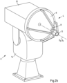
- Fig. 2a shows the optical sensor 2 already described above for monitoring airspace for a site, with an FTIR spectrometer 12 for detecting target substances, with infrared optics 4 for imaging a partial section of the airspace of the site to be monitored onto the FTIR spectrometer 12, with a video camera 10, and with a positioning unit 14 for aligning the sensor unit formed from the FTIR spectrometer 12, the infrared optics 4, and the camera 10.
- the infrared optics 4 and the camera 10 essentially capture the same solid angle; in particular, the optical axis O 1 of the infrared optics and the optical axis O 2 of the camera 10 are aligned parallel to one another.
- the infrared optics 4 are designed as a Cassegrain telescope with a parabolic mirror 6 and a secondary mirror 8.
- the infrared optics can also be designed as a lens optic.
- Camera 10 is positioned laterally to the infrared optics 4 and therefore has sufficient space to be equipped with a telephoto lens, thus producing high-quality images of the monitored section of the terrain's airspace.
- parallax must be compensated for by adjusting the distance between the optical axes.
- Fig. 2b shows a further embodiment of an optical sensor 2.
- a camera 11 is arranged in the optical axis of the infrared optics 4 at the front end of the secondary mirror.
- the optical axis O2 of the infrared optics 4 and the optical axis O3 of the camera 11 coincide, and a parallax effect is avoided.
- smartphone cameras with a telephoto function are already known, so that the camera 10 can be completely replaced.
- Fig. 2c shows a further embodiment of an optical sensor 2.
- the camera is designed as a camera system with a camera 10 arranged laterally to the infrared optics 4 and with a camera 11 arranged in the optical axis O 2 of the infrared optics 4.
- the optical axis O 1 of the camera 10 runs at a distance from the optical axis O 2 of the infrared optics 4, with the optical axis O 3 of the camera 11 coinciding with the optical axis O 2 and thus having no or only a small distance from it.
- Fig. 3 shows a schematic representation of the monitoring by two optical sensors 2a and 2b.
- the first optical sensor 2a has a monitoring area, indicated by dashed lines, which is approximately 35° wide.
- the optical sensor 2a usually scans the monitoring area at least partially along a predetermined path.
- the second optical sensor 2b has a monitoring area of approximately 90°, also indicated by dashed lines.
- the second optical sensor 2b also automatically scans the monitoring area, at least partially, along a preset path. Preferably, the scanning is repeated cyclically.
- the monitoring areas of both optical sensors overlap.
- the data is transferred to the server 30 and combined with the position data (spatial angle).
- the spectral intensity distribution of the received IR radiation is derived for each solid angle from the measurement data of the optical sensors 2a and 2b in order to identify at least one target substance by correlating the intensity distribution with known gas spectra.
- a corresponding computer program runs on the server 30 or, if applicable, in the optical sensors 2a and 2b.
- the further optical sensor 2b is controlled to scan the overlap area with the monitoring area of the first optical sensor.
- a further solid angle ⁇ 2 with an infrared signal of the target substance is identified, so that the coordinates of the overlapping area (black area) with increased concentration of the target substance can be determined from the solid angle information of the first solid angle ⁇ 1 and the further solid angle ⁇ 2 .
- Fig. 4 shows an extended view of Fig. 3 , in which the dotted areas of the monitoring areas of the optical sensors 2a and 2b represent the solid angle ranges in which at least a low concentration of the target substance has been identified.
- the already in Fig. 3 The solid angle ranges ⁇ 1 and ⁇ 2 shown show the solid angle ranges with the highest concentration of the target substance, which was determined by calculating the column density. For the calculation of the column density, see the general description above.
- Fig. 4 can therefore not not only the center of the gas cloud of the target substance (black field), but also the extent of the cloud can be determined.
- Fig. 5 shows a similar figure as in Fig. 4
- a tower 40 is located on the monitored area within the monitoring range of the second optical sensor 2b, so that the area located behind the tower 40 by the optical sensor 2b is shadowed.
- the shadowed area cannot therefore be monitored by the optical sensor 2b; the measuring radius of the optical sensor 2b in this area only extends to the tower 40 and thus not to the monitoring range of the optical sensor 2a. For this reason, the "shadow" is not dotted in Fig. 5 shown.
- the measurement signals of the optical sensor 2b in spatial directions with too small a measurement radius are not included in the evaluation.
- the measurement radii are too small for the solid angles covered by the tower 40, and the monitoring areas of the sensors 2a, 2b do not overlap in a shadow behind the tower 40. Nevertheless, the extent of the cloud of target substance can be almost completely recorded.
- the evaluation is not distorted, because in the monitoring area ending at the tower 40, the measurement signal will not provide any indication of the target substance, even though this would be the case without the presence of the tower 40 (see Fig. 4 .
- the server 20 can be configured, i.e., by applying computer programs, to replace the measurement signals of the additional optical sensor 2b that were not included in the evaluation by mathematical interpolation of adjacent measurement signals of the optical sensor 2b.
- Adjacent measurement signals are those whose associated solid angle ranges are arranged adjacent to the solid angle ranges of the non-included measurement signals.
- the Fig. 6 and 7 show a system for monitoring an airspace for an area of a harbor basin, in which the two optical sensors 2a and 2b are positioned at prominent positions within the harbor area.
- Fig. 6 The standard case is shown, in which the two optical sensors 2a and 2b independently scan the airspace above the terrain within the surveillance areas marked with dashed lines.
- Fig. 7 shows the event as previously described.
- the server 20 is configured by using a computer program to determine the coordinates of the overlap area (black area in Fig. 7 ) of the solid angle ranges ⁇ 1 and ⁇ 2 of the highest column densities of the two optical sensors 2a and 2b and to link the coordinates to a map representation and create a two-dimensional representation of the event.
- a three-dimensional representation can also be created by linking with images from the cameras 11 of the sensors 2a, 2b.
- Fig. 8 shows another system for monitoring airspace for an extensive chemical production site.
- two optical sensors 2a and 2b are arranged in prominent positions.
- three active infrared radiation sources 18a, 18b and 18c are arranged in such a way that one of the optical sensors 2a or 2b receives the infrared light. This way, along the established measuring sections (thick lines in Fig. 8 ) enables more precise measurement of the gases contained in the atmosphere.
- the spectral range for evaluation can be broadened, allowing a larger number of target substances to be measured.
- the active measurements enable, among other things, more precise background determination of the gas distribution and a larger target substance library.
- the active infrared radiation sources 18a, 18b, and 18c enable separate monitoring of predefined boundary areas, such as plant boundaries.
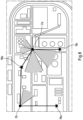
- Fig. 9 shows a cartographic representation of another chemical plant with partial shading of the monitoring areas of three optical sensors 2a, 2b and 2c.
- Buildings 50, 52, and 54 are located on the site, which partially shade the monitoring area of the optical sensor 2a, resulting in shadow areas A1 , A2 , and A3 .
- the monitoring area of the optical sensor 2a therefore extends only to buildings 50, 52, and 54, respectively, in the assigned spatial angles.
- shadowing areas B 1 and B 2 result for the optical sensor 2b and shadowing areas C 1 , C 2 and C 3 result for the optical sensor 2c.
- Fig. 9 shows the system with the three optical sensors 2a, 2b and 2c with a target substance cloud 56.
- the target substance cloud 56 is usually detected first by the sensor 2a of the scanning optical sensors 2a, 2b and 2c and an event is determined.
- the server (not shown in this figure) is configured to select at least one additional optical sensor 2b for control in this event, the monitoring range of which has a maximum overlap with the monitoring range of the first optical sensor 2a.
- the shadows B 1 and B 2 lie outside the solid angle range ⁇ 1 of the first optical sensor 2a, so that a maximum overlap is provided by the monitoring range of the sensor 2b.
- the second sensor 2b detects the target substance cloud 56 within the solid angle range ⁇ 2 , and the target substance cloud 56 is localized.
- the third sensor 2c is not selected in this scenario because the shadowing area C 3 overlaps part of the solid angle range ⁇ 1. A selection of the optical sensor 2c would then also not have led to a positive measurement of the target cloud 56 because the target cloud 56 is completely in the Shadowing area C 3 . The measuring radius of the third sensor 2c is therefore too small in the solid angle range ⁇ 3 .
- the potential solid angle ⁇ 3 is only shown in dashed lines, since the shadowing by the building 52 prevents a measurement of the target substance cloud 56.
- Fig. 10 shows the representation from Fig. 9 with a changed location of the detected target substance cloud 56.
- the server After the optical sensor 2a has detected the target substance cloud, the server searches for another optical sensor to locate the target substance cloud 56. It is determined that both optical sensors 2b and 2c each have a shadowing area that overlaps with the solid angle range ⁇ 1 . However, the server does not select the optical sensor 2b because the position of the optical sensor 2b lies in the direction of the solid angle range ⁇ 1 of the first optical sensor 2a with detected target substance. Therefore, the third optical sensor 2c, whose monitoring area has a solid angle with a larger angle to the measured solid angle range ⁇ 1 of the first optical sensor 2a, is selected to identify the target substance cloud 56, determine the solid angle range ⁇ 3 , and thus the coordinates of the target substance cloud 56.
- Fig. 11 shows a further embodiment of a system according to the invention, which is based on the embodiment according to Fig. 8 builds up.
- stationary detectors 60 are configured as chemo-electrical detectors.
- the server (not shown here) is configured to use an output signal of the at least one stationary detector 60 as a triggering signal for the deployment of the optical sensors 2a, 2b in the spatial region of the stationary detector.
- a plurality of detectors 60 are shown, all of which are positioned in solid angle ranges that can be detected by the optical sensors 2a and 2b. Even though several detectors 60 are shown here, are, it is sufficient within the scope of the invention if only one detector 60 is present.
- the detector 60 arranged in the cloud 62 can detect the target substance and send a corresponding signal to the server. Subsequently, the two optical sensors 2a and 2b, if they have not yet detected the event, can detect the gas cloud 62 and process it as described above.
- At least one mobile sensor 70 can be mounted on a drone 72.
- the mobile sensor 70 can be designed as an optical sensor 2 or as a detector 60.
- the mobile sensor 70 is guided to the cloud 62 in the event of an incident and can take additional measurements on site, which can be evaluated by the system and the server.
- the measurement signal of the mobile sensor 70 can be evaluated together with the measurement signals of the other stationary optical sensors 2a and 2b, as previously described.
- the variability of the positions of the mobile sensor 70 can allow additional data to be acquired in addition to the measured values of the stationary detector 60.
- Fig. 12 shows another embodiment of a system for monitoring airspace for a terrain.
- This system essentially corresponds to the system according to Fig. 4 , but only one optical sensor 2 with a passive Fourier transform infrared spectrometer is present.
- a server (not shown) is used to evaluate the measured data and to control the optical Sensor 2 is provided.
- the optical sensor 2 has - as described - an adjustable monitoring range.
- a mobile, airworthy sensor 70 of the type described above is provided, which is attached to a drone 72 described above.
- the mobile sensor 70 is controlled by the server to detect the concentration of the target substance along the solid angle identified by the optical sensor 2 in a location-dependent manner.
- the corresponding flight route is shown in Fig. 12 shown in dashed lines.
- the location of the maximum concentration of the target substance can be determined.
Landscapes
- Physics & Mathematics (AREA)
- General Physics & Mathematics (AREA)
- Life Sciences & Earth Sciences (AREA)
- Health & Medical Sciences (AREA)
- Chemical & Material Sciences (AREA)
- Spectroscopy & Molecular Physics (AREA)
- General Health & Medical Sciences (AREA)
- Analytical Chemistry (AREA)
- Biochemistry (AREA)
- Immunology (AREA)
- Pathology (AREA)
- Engineering & Computer Science (AREA)
- Business, Economics & Management (AREA)
- Tourism & Hospitality (AREA)
- General Life Sciences & Earth Sciences (AREA)
- Geophysics (AREA)
- Medicinal Chemistry (AREA)
- Human Resources & Organizations (AREA)
- Marketing (AREA)
- Primary Health Care (AREA)
- Strategic Management (AREA)
- General Business, Economics & Management (AREA)
- Theoretical Computer Science (AREA)
- Economics (AREA)
- Food Science & Technology (AREA)
- Combustion & Propulsion (AREA)
- Investigating Or Analysing Materials By Optical Means (AREA)
Description
Die Erfindung betrifft ein System und Verfahren zur Überwachung eines Luftraumes für ein Gelände wie z.B. industrielle chemische Anlagen, Häfen oder kritische Verkehrsinfrastruktur. Insbesondere dient die Erfindung der Detektion und Lokalisation von Gasleckagen und potenziell gefährlichen Gaswolken.The invention relates to a system and method for monitoring airspace for an area such as industrial chemical plants, ports, or critical transport infrastructure. In particular, the invention serves to detect and localize gas leaks and potentially dangerous gas clouds.
Auf den genannten Geländen können durch Undichtigkeiten oder Fehlfunktionen von Anlagen Gase austreten, die für die Umwelt schädlich sind, zu Unfällen mit weitreichenden Folgen führen können und Gefahren für Gesundheit und Leben der sich auf dem Gelände aufhaltenden Personen darstellen können.Leaks or malfunctions of systems on the aforementioned sites may cause gases to escape that are harmful to the environment, can lead to accidents with far-reaching consequences and can pose a threat to the health and life of people on the site.
Eine gängige Überwachung eines Geländes erfolgt mit chemo-elektrischen Sensoren, die jeweils nur für ein Gas oder eine geringe Anzahl von chemischen Gasen empfindlich sind. Zudem müssen die Sensoren dort angeordnet sein, wo die Gase in der Umgebungsluft vorhanden sind. Daher ist die Anzahl der einzusetzenden Sensoren hoch.Common site monitoring is done with chemoelectric sensors, each of which is sensitive to only one or a small number of chemical gases. Furthermore, the sensors must be located where the gases are present in the ambient air. Therefore, the number of sensors required is high.
Weiterhin ist die Anwendung von Fourier-Transform-Infrarot-Spektrometern (FTIR) bekannt, die in kurzen Zeitabständen die Zusammensetzung des beobachteten Raumwinkels oberhalb des Geländes auf das Vorhandensein verschiedener chemischer Gase bestimmen können. Damit kann das ungewollte Austreten von Gasen detektiert werden und mittels Triangulation der Ort ermittelt werden. Jedoch mangelt es den bekannten Verfahren an einer guten räumlichen Auflösung und somit einer zuverlässigen Lokalisation der Austrittsstelle, insbesondere bei einer Beeinträchtigung der Sichtverhältnisse durch topographische Hindernisse.Furthermore, the use of Fourier transform infrared spectrometers (FTIR) is known. These can determine the composition of the observed solid angle above the terrain for the presence of various chemical gases at short time intervals. This allows unwanted gas leaks to be detected and their location determined using triangulation. However, these methods lack good spatial resolution and thus a reliable localization of the leak site, especially when visibility is impaired by topographical obstacles.
Ein aus dem Stand der Technik bekanntes FTIR-Spektrometer dient dabei als optischer Sensor. Das Spektrometer selbst ist ortsfest ausgebildet und dessen Infrarot-Optik ist in einem nach oben gerichteten Winkel ausgerichtet. Mit einem schwenkbaren Spiegel wird das Umgebungslicht auf die Infrarot-Optik gerichtet und somit die Umgebung gescannt. Der Überwachungsbereich ist dabei allerdings auf einen geringen Raumwinkelbereich beschränkt.A state-of-the-art FTIR spectrometer serves as the optical sensor. The spectrometer itself is stationary, and its infrared optics are aligned at an upward angle. A pivoting mirror directs ambient light onto the infrared optics, thus scanning the surroundings. However, the monitoring area is limited to a small solid angle.
Die
Die
Daher liegt der vorliegenden Erfindung das technische Problem zugrunde, ein System und ein Verfahren zur Überwachung eines Luftraumes für ein ausgedehntes Gelände zu verbessern.Therefore, the present invention is based on the technical problem of improving a system and a method for monitoring an airspace for an extensive area.
Das zuvor aufgeführte technische Problem wird erfindungsgemäß durch ein System und durch ein Verfahren der nachfolgend beschriebenen Art und Weise gelöst.The technical problem described above is solved according to the invention by a system and by a method of the manner described below.
Das System zur Überwachung eines Luftraumes für ein ausgedehntes Gelände ist gemäß einer ersten Lehre der Erfindung ausgerüstet mit mindestens zwei optischen Sensoren mit einem passiven Fourier-Transform-Infrarotspektrometer und mit einem Server zur Auswertung der Messdaten und zur Steuerung der mindestens zwei optischen Sensoren, wobei jeder optischer Sensor einen einstellbaren Überwachungsbereich aufweist und wobei sich die Überwachungsbereiche der mindestens zwei optische Sensoren zumindest abschnittsweise überlappen und wobei der Server eingerichtet, die optischen Sensoren im Regelfall zu einem automatischen Scannen der Überwachungsbereiche anzusteuern, wobei der Server den Messdaten jeweils einen Raumwinkel anhand der Positionsdaten des optischen Sensors zuordnet, aus den Messdaten der optischen Sensoren für jeden Raumwinkel die spektrale Intensitätsverteilung der empfangenen IR-Strahlung abzuleiten und mittels Korrelation der Intensitätsverteilung mit bekannten Gasspektren, mindestens einen Zielstoff zu identifizieren, im Ereignisfall, wenn ein erster optischer Sensor in einem ersten Raumwinkel einen Zielstoff identifiziert, mindestens einen weiteren optischen Sensor anzusteuern, den Überlappungsbereich mit dem Überwachungsbereich des ersten optischen Sensors zu scannen, aus den Messdaten des mindestens einen weiteren optischen Sensors mindestens einen weiteren Raumwinkel mit einem Infrarotsignal des Zielstoffes zu identifizieren und aus den Raumwinkelinformationen des ersten Raumwinkels und des mindestens einen weiteren Raumwinkels die Koordinaten des Überlappungsbereiches mit erhöhter Konzentration des Zielstoffes zu ermitteln. Das System ist dadurch gekennzeichnet, dass der Überwachungsbereich jedes optischen Sensors durch die Topographie und/oder die Bebauung des Geländes aufgrund von Abschattungen abhängig vom Raumwinkel unterschiedliche Messradien aufweist und der Überwachungsbereich jedes optischen Sensors durch den Raumwinkelbereich und die zugehörigen Messradien festgelegt ist und dass die Messsignale des mindestens einen weiteren optischen Sensors in Raumrichtungen mit zu geringem Messradius nicht in die Auswertung einbezogen werden.The system for monitoring an airspace for an extensive area is, according to a first teaching of the invention, equipped with at least two optical sensors with a passive Fourier transform infrared spectrometer and with a server for evaluating the measurement data and for controlling the at least two optical sensors, wherein each optical sensor has an adjustable monitoring area and wherein the monitoring areas of the at least two optical sensors overlap at least in sections and wherein the server is set up to connect the optical sensors to a to control automatic scanning of the monitoring areas, wherein the server assigns a solid angle to each measurement data based on the position data of the optical sensor, to derive the spectral intensity distribution of the received IR radiation for each solid angle from the measurement data of the optical sensors and to identify at least one target substance by correlating the intensity distribution with known gas spectra, to control at least one further optical sensor in the event of an incident when a first optical sensor identifies a target substance in a first solid angle, to scan the overlap area with the monitoring area of the first optical sensor, to identify at least one further solid angle with an infrared signal of the target substance from the measurement data of the at least one further optical sensor and to determine the coordinates of the overlap area with an increased concentration of the target substance from the solid angle information of the first solid angle and the at least one further solid angle. The system is characterized in that the monitoring area of each optical sensor has different measuring radii depending on the solid angle due to the topography and/or the development of the area due to shadowing, and the monitoring area of each optical sensor is determined by the solid angle range and the associated measuring radii, and that the measuring signals of the at least one further optical sensor in spatial directions with an insufficient measuring radius are not included in the evaluation.
Das System wird so verstanden, dass es insbesondere, aber nicht nur bei größeren Systemen mit einer Mehrzahl von optischen Sensoren ausreicht, wenn sich die Überwachungsbereiche von jeweils zumindest zwei optischen Sensoren (2; 2a, 2b, 2c) zumindest abschnittsweise überlappen. Somit werden notwendiger Weise paarweise, jedoch nicht von allen Paaren von optischen Sensoren eine Überlappung der Überwachungsbereiche gefordert. Ein Gesamtsystem kann somit auch als eine Kombination von mehreren Systemen verstanden werden, bei denen sich die Überwachungsbereiche aller der mindestens zwei optischen Sensoren zumindest abschnittsweise überlappen.The system is understood to be sufficient, particularly but not exclusively in larger systems with a plurality of optical sensors, if the monitoring areas of at least two optical sensors (2; 2a, 2b, 2c) overlap at least partially. Thus, an overlap of the monitoring areas is necessarily required in pairs, but not for all pairs of optical sensors. An overall system can thus also be understood as a combination of several systems in which the monitoring areas of all of the at least two optical sensors overlap at least partially.
Der genannte Server kann dabei auch als Auswerteeinheit oder als Auswerte- und Steuerungseinheit bezeichnet werden.The server mentioned can also be referred to as an evaluation unit or as an evaluation and control unit.
Der Server kann vorzugsweise auch mehrere voneinander getrennte Untereinheiten aufweisen, die bevorzugt jeweils in einem optischen Sensor integriert oder zumindest benachbart angeordnet sind. Beispielsweise kann der Sensor je eine Untereinheit aufweisen, die zusammen den Server bzw. die Auswerteeinheit bilden. Ferner können verschiedene Aufgaben des Servers durch Untereinheiten übernommen werden. So kann beispielsweise eine erste Untereinheit des Servers die Messdaten auswerten und eine zweite Untereinheit einen oder mehrere optische Sensoren steuern.The server can preferably also have several separate subunits, each of which is preferably integrated into an optical sensor or at least arranged adjacent to it. For example, the sensor can have a subunit each, which together form the server and the evaluation unit, respectively. Furthermore, various tasks of the server can be performed by subunits. For example, a first subunit of the server can evaluate the measurement data, and a second subunit can control one or more optical sensors.
In einer bevorzugten Ausführungsform ist der Server als zentrale Steuereinheit ausgebildet, die zwei oder mehr optische Sensoren steuert und/oder die Messdaten von zwei oder mehr optischen Sensoren auswertet. Besonders bevorzugt steuert die zentrale Steuereinheit alle Sensoren und/oder wertet die Messdaten aller optischen Sensoren des Systems aus. Der Server kann vorzugsweise mit großem räumlichen Abstand zu den optischen Sensoren angeordnet sein. Ferner kann der Server auch ein wechselnder Server eines Servernetzwerks sein. Beispielsweise können das Auswerten der Messdaten und/oder das Steuern der optischen Sensoren auch unter Verwendung einer Cloud erfolgen, die von einem oder mehreren Servern bereitgestellt wird.In a preferred embodiment, the server is designed as a central control unit that controls two or more optical sensors and/or evaluates the measurement data from two or more optical sensors. Particularly preferably, the central control unit controls all sensors and/or evaluates the measurement data from all optical sensors in the system. The server can preferably be located at a large spatial distance from the optical sensors. Furthermore, the server can also be a changing server in a server network. For example, the evaluation of the measurement data and/or the control of the optical sensors can also be carried out using a cloud provided by one or more servers.
Innerhalb eines Raumwinkels entspricht der Messradius dabei der maximalen Entfernung, bis zu der der optische Sensor ein Messsignal aufnehmen kann. Der Messradius kann der maximale Messradius sein, den der optische Sensor realisieren kann. Der Messradius kann aber auch aufgrund einer Abschattung durch ein Hindernis in seiner räumlichen Erstreckung begrenzt, also kürzer sein. Der optische Sensor kann also in diesem Raumwinkel keine Messdaten für den Bereich hinter dem Hindernis erzeugen. Die Messradien pro Raumwinkel werden bei der Installation des Systems für die optischen Sensoren anhand der bekannten Topographie und/oder Bebauung des Geländes bestimmt und festgelegt.Within a solid angle, the measuring radius corresponds to the maximum distance up to which the optical sensor can record a measurement signal. The measuring radius can be the maximum measuring radius that the optical sensor can achieve. However, the measuring radius can also be limited in its spatial extent due to shadowing by an obstacle, i.e., shorter. The optical sensor cannot therefore generate measurement data for the area behind the obstacle within this solid angle. The measuring radii per solid angle are determined during installation of the System for the optical sensors is determined and specified based on the known topography and/or development of the site.
Die Messradien der optischen Sensoren sind bevorzugt abhängig vom Raumwinkel einstellbar. Der Messradius wird dabei für jeden Raumwinkel ausgehend vom optischen Sensor bis zur maximalen Entfernung oder bis zu einem eine Abschattung verursachenden Hindernis eingestellt. Vorzugsweise ist das System dazu ausgebildet, die Messradien für die Raumwinkel, vorzugsweise aus zwei- und/oder dreidimensionalen Kartendaten, automatisch zu definieren. Beispielsweise und bevorzugt kann das System dazu eingerichtet sein, die Messradien unter Verwendung eines digitalen Zwillings und/oder eines vereinfachten dreidimensionalen Modells des zu überwachenden Geländes zu definieren. Ferner bevorzugt ist das System dazu eingerichtet, mittels einer Kamera des optischen Sensors Hindernisinformationen zu erfassen, und die Messradien unter Verwendung der Hindernisinformationen zu definieren. Die Hindernisinformationen korrespondieren bevorzugt zu optischen Hindernissen, die vorzugsweise entlang einer optischen Achse des Sensors angeordnet sind. Besonders bevorzugt ist das System eingerichtet, die Messradien unter Verwendung von Hindernisinformationen mehrerer optischer Sensoren zu definieren.The measuring radii of the optical sensors are preferably adjustable depending on the solid angle. The measuring radius is set for each solid angle, starting from the optical sensor up to the maximum distance or up to an obstacle causing shadowing. The system is preferably designed to automatically define the measuring radii for the solid angles, preferably from two- and/or three-dimensional map data. For example, and preferably, the system can be configured to define the measuring radii using a digital twin and/or a simplified three-dimensional model of the terrain to be monitored. Furthermore, the system is preferably configured to capture obstacle information using a camera of the optical sensor and to define the measuring radii using the obstacle information. The obstacle information preferably corresponds to optical obstacles, which are preferably arranged along an optical axis of the sensor. Particularly preferably, the system is configured to define the measuring radii using obstacle information from multiple optical sensors.
Unter einem Raumwinkel wird weiterhin ein räumlicher Raumwinkelbereich verstanden, den der optische Sensor auflösen kann. Der Raumwinkelbereich eines Raumwinkels, also die räumliche Auflösung des optischen Sensors kann innerhalb des Systems einstellbar sein. Für jeden Raumwinkel des Raumwinkelbereichs entspricht somit der zugehörige Messradius der maximalen Entfernung, bis zu der der optische Sensor ein Messsignal aufnehmen kann. Für alle Raumwinkel des Raumwinkelbereichs kann der optische Sensor optische Signale empfangen und korrespondierende Messsignale bereitstellen.A solid angle is also understood to be a spatial solid angle range that the optical sensor can resolve. The solid angle range of a solid angle, i.e., the spatial resolution of the optical sensor, can be adjusted within the system. For each solid angle within the solid angle range, the corresponding measuring radius corresponds to the maximum distance up to which the optical sensor can record a measurement signal. The optical sensor can receive optical signals and provide corresponding measurement signals for all solid angles within the solid angle range.
Somit werden also Messsignale eines optischen Sensors nur dann verwendet, wenn der zugehörige Messradius des optischen Sensors bis zu einem erforderlichen Überlappungsbereich mit dem Überwachungsbereichs eines anderen optischen Sensors reicht.Thus, measurement signals from an optical sensor are only used if the corresponding measuring radius of the optical sensor is up to a required Overlap area with the monitoring area of another optical sensor.
Der Server ist vorzugsweise für eine der vorbeschriebenen Funktionen auch dann eingerichtet, wenn nur eine Komponente des Servers für eine der vorbeschriebenen Funktionen eingerichtet ist. Beispielsweise kann der Server als Auswerteeinheit dazu eingerichtet sein, die optischen Sensoren im Regelfall zu einem automatischen Scannen der Überwachungsbereiche anzusteuern und/oder den Messdaten jeweils einen Raumwinkel anhand der Positionsdaten des optischen Sensors zuzuordnen. Wenn also ein erster optischer Sensor einen Zielstoff identifiziert, steuert der Server einen weiteren Sensor an, um einen Überlappungsbereich des Überwachungsbereichs des ersten Sensors mit dem Überwachungsbereich des weiteren Sensors zu scannen. Hierdurch kann das System vorzugsweise eine von dem ersten optischen Sensor erfolgte Identifikation des Zielstoffs verifizieren.The server is preferably configured for one of the functions described above, even if only one component of the server is configured for one of the functions described above. For example, the server can be configured as an evaluation unit to normally control the optical sensors to automatically scan the monitoring areas and/or to assign a solid angle to the measurement data based on the position data of the optical sensor. Thus, if a first optical sensor identifies a target substance, the server controls a further sensor to scan an overlap area of the monitoring area of the first sensor with the monitoring area of the further sensor. This preferably allows the system to verify an identification of the target substance made by the first optical sensor.
Des Weiteren ist der Server eingerichtet, die Messsignale des mindestens einen weiteren optischen Sensors, die nicht in die Auswertung einbezogen worden sind, durch mathematische Interpolation, insbesondere eine gewichtete Interpolation von räumlich angrenzenden Messsignalen zu ersetzen. Angrenzende Messsignale sind dabei Messsignale, die für Raumwinkel bereitgestellt werden, die im Raumwinkelbereich räumlich benachbart zu demjenigen Raumwinkel mit zu geringem Messradius liegen.Furthermore, the server is configured to replace the measurement signals of the at least one additional optical sensor that were not included in the evaluation by mathematical interpolation, in particular a weighted interpolation of spatially adjacent measurement signals. Adjacent measurement signals are measurement signals provided for solid angles that are spatially adjacent to the solid angle with an insufficient measurement radius.
Weiterhin sind mindestens drei optische Sensoren vorgesehen und der Server ist eingerichtet, im Ereignisfall zumindest einen weiteren optischen Sensor für eine Ansteuerung auszuwählen, dessen Überwachungsbereich eine maximale Überlappung mit dem Überwachungsbereich des ersten optischen Sensors aufweist.Furthermore, at least three optical sensors are provided and the server is configured to select at least one further optical sensor for activation in the event of an event, the monitoring area of which has a maximum overlap with the monitoring area of the first optical sensor.
Vorzugsweise ist der Server eingerichtet, einen Raumwinkel des ersten optischen Sensors, für den der Zielstoff identifiziert wird, mit den Überwachungsbereichen der weiteren Sensoren abzugleichen und einen weiteren optischen Sensor für eine Ansteuerung auszuwählen, dessen Überwachungsbereich den Überwachungsbereich des ersten Sensors für denjenigen Raumwinkel überlappt, für den der erste optische Sensor den Zielstoff identifiziert.Preferably, the server is configured to compare a solid angle of the first optical sensor, for which the target substance is identified, with the monitoring areas of the further sensors and to use a further optical sensor for a Select a control whose monitoring range overlaps the monitoring range of the first sensor for the solid angle for which the first optical sensor identifies the target substance.
In bevorzugter Weise ist der Server eingerichtet, einen ausgewählten optischen Sensor nicht einzusetzen, wenn die Position des ausgewählten optischen Sensors in Richtung des Raumwinkelbereichs des ersten optischen Sensors mit nachgewiesenem Zielstoff liegt. In einem solchen Fall wird vorzugsweise der nächstbeste optische Sensor ausgewählt, der eine möglichst große Überlappung mit dem Überwachungsbereich des ersten optischen Sensors aufweist.Preferably, the server is configured not to use a selected optical sensor if the position of the selected optical sensor lies in the direction of the solid angle range of the first optical sensor with detected target substance. In such a case, the next best optical sensor is preferably selected, which has the greatest possible overlap with the monitoring range of the first optical sensor.
So kann erreicht werden, dass die optische Achse des ersten Sensors für den Raumwinkel, für den der Zielstoff identifiziert wird, und die optische Achse des weiteren optischen Sensors, der zum Scannen des Überlappungsbereichs angesteuert wird, winklig zueinander angeordnet sind. Aus den Raumwinkeln der optischen Sensoren, für die der Zielstoff identifiziert wird, kann dann vorzugsweise mittels Triangulation eine Position des Zielstoffs ermittelt werden.This makes it possible to arrange the optical axis of the first sensor for the solid angle for which the target substance is identified and the optical axis of the additional optical sensor, which is controlled to scan the overlap area, at an angle to each other. From the solid angles of the optical sensors for which the target substance is identified, a position of the target substance can then be determined, preferably by triangulation.
Weiterhin ist es vorteilhaft, wenn der Server eingerichtet ist, aus den Messdaten der optischen Sensoren die Säulendichten des Zielstoffes zu ermitteln, wobei die Säulendichte das mathematische Produkt aus Konzentration des Gases (gemessen in ppm) und der räumlichen Länge der Gaswolke (gemessen in m) ist und wobei der Server eingerichtet ist, die Koordinaten des Überlappungsbereiches der höchsten Säulendichten verschiedener optischer Sensoren zu ermitteln.Furthermore, it is advantageous if the server is configured to determine the column densities of the target substance from the measurement data of the optical sensors, wherein the column density is the mathematical product of the concentration of the gas (measured in ppm) and the spatial length of the gas cloud (measured in m), and wherein the server is configured to determine the coordinates of the overlap area of the highest column densities of different optical sensors.
In einer bevorzugten Ausgestaltung ist das System und ist insbesondere der Server eingerichtet, im Ereignisfall mittels des ersten optischen Sensors eine Säulendichte des Zielstoffs im ersten Raumwinkel zu bestimmen und eine Säulendichte des Zielstoffs in an den ersten Raumwinkel angrenzenden Raumwinkeln zu bestimmen. An den ersten Raumwinkel angrenzende Raumwinkel schließen vorzugsweise kontinuierlich an den ersten Raumwinkel an. Es ist aber auch bevorzugt, dass ein angrenzender Raumwinkel einen vordefinierten Winkelabstand zum ersten Raumwinkel hat. Wenn beispielsweise der erste Raumwinkel einen Wert von 45° aufweist, können angrenzende Raumwinkel beispielsweise Werte von 44° und 46° aufweisen.In a preferred embodiment, the system and in particular the server are configured to determine, in the event of an event, by means of the first optical sensor, a column density of the target substance in the first solid angle and to determine a column density of the target substance in solid angles adjacent to the first solid angle. Solid angles adjacent to the first solid angle preferably adjoin the first solid angle continuously. However, it is also preferred that a Adjacent solid angles have a predefined angular distance from the first solid angle. For example, if the first solid angle has a value of 45°, adjacent solid angles can have values of 44° and 46°.
Gemäß einer bevorzugten Weiterbildung ist das System und insbesondere der Server eingerichtet, aus dem ersten Raumwinkel und den angrenzenden Raumwinkeln denjenigen Raumwinkel mit der höchsten Säulendichte des Zielstoffs zu identifizieren und mittels des ersten optischen Sensors eine Säulendichte des Zielstoffs in einem an den Raumwinkel mit der höchsten Säulendichte angrenzenden Raumwinkel zu bestimmen. Das System ist also eingerichtet, die im ersten Schritt bestimmten und den Raumwinkeln zugeordneten Säulendichten des Zielstoffs zu vergleichen und denjenigen Raumwinkel zu ermitteln, unter dem die höchste Säulendichte des Zielstoffs bestimmt wird. Anschließend wird zu einem an diesen Raumwinkel der höchsten Zielstoffsäulendichte angrenzenden Raumwinkel erneut die Säulendichte des Zielstoffs bestimmt. Als angrenzender Raumwinkel wird vorzugsweise ein Raumwinkel mit unbekannter Säulendichte des Zielstoffs gewählt. Wird beispielsweise wie obenstehend beschrieben unter einem Raumwinkel von 44° die höchste Säulendichte des Zielstoffs bestimmt, wird anschließend die Säulendichte des Zielstoffs für einen Raumwinkel mit einem Wert von 43° ermittelt.According to a preferred development, the system and in particular the server are configured to identify the solid angle with the highest column density of the target substance from the first solid angle and the adjacent solid angles and to determine a column density of the target substance in a solid angle adjacent to the solid angle with the highest column density by means of the first optical sensor. The system is therefore configured to compare the column densities of the target substance determined in the first step and assigned to the solid angles and to determine the solid angle at which the highest column density of the target substance is determined. The column density of the target substance is then determined again for a solid angle adjacent to this solid angle of the highest target substance column density. A solid angle with an unknown column density of the target substance is preferably selected as the adjacent solid angle. For example, if the highest column density of the target substance is determined at a solid angle of 44° as described above, the column density of the target substance is subsequently determined for a solid angle with a value of 43°.
Vorzugsweise ist das System und ist insbesondere der Server eingerichtet, den Raumwinkel des Überwachungsbereichs des ersten optischen Sensors zu bestimmen, der im Ereignisfall die höchste Säulendichte des Zielstoffs aufweist. Hierfür ist das System eingerichtet, die zuvor beschriebenen Schritte auszuführen, bis derjenige Raumwinkel ermittelt ist, für den die Säulendichte des Zielstoffs maximal ist. Wird beispielsweise unter 43° und 45° eine geringere Säulendichte des Zielstoffs ermittelt, als für einen Raumwinkel von 44°, ist der Raumwinkel mit dem Wert von 44° derjenige Raumwinkel des Überwachungsbereichs, der die höchste Säulendichte des Zielstoffs aufweist. Das System kann aber auch dazu ausgebildet sein, mehrere lokale Maxima der Säulendichte des Zielstoffs im Überwachungsbereich zu ermitteln.Preferably, the system, and in particular the server, is configured to determine the solid angle of the monitoring area of the first optical sensor that has the highest column density of the target substance in the event of an event. For this purpose, the system is configured to carry out the steps described above until the solid angle is determined for which the column density of the target substance is maximum. For example, if a lower column density of the target substance is determined between 43° and 45° than for a solid angle of 44°, the solid angle with the value of 44° is the solid angle of the monitoring area that has the highest column density of the target substance. However, the system can also be configured to determine several local maxima of the column density of the target substance in the monitoring area.
Bevorzugt ist das das System und insbesondere der Server eingerichtet, im Ereignisfall einen zu den Raumwinkeln des ersten optischen Sensors korrespondierenden ersten Konzentrationsgradienten des Zielstoffs zu bestimmen. Der Konzentrationsgradient ist ein Maß für die Änderung der Zielstoffsäulendichte je diskretem Raumwinkelschritt.Preferably, the system, and in particular the server, is configured to determine, in the event of an event, a first concentration gradient of the target substance corresponding to the solid angles of the first optical sensor. The concentration gradient is a measure of the change in the target substance column density per discrete solid angle step.
In einer bevorzugten Weiterbildung ist das System und insbesondere der Server eingerichtet, im Ereignisfall aus dem zu Raumwinkeln des ersten optischen Sensors korrespondierenden ersten Konzentrationsgradienten und einem analogen weiteren Konzentrationsgradienten eines weiteren optischen Sensors einen mehrdimensionalen Konzentrationsgradienten des Zielstoffs zu bestimmen. Vorzugsweise werden also zu den Raumwinkeln einer Mehrzahl von Sensoren Konzentrationsgradienten bestimmt und vom System kombiniert, um den mehrdimensionalen Konzentrationsgradienten zu bestimmen. Beispielsweise kann der mehrdimensionale Konzentrationsgradient ein Maß für die Änderung der Zielstoffsäulendichte in einer ersten Raumrichtung und in einer zur ersten Raumrichtung senkrechten Raumrichtung sein.In a preferred development, the system, and in particular the server, is configured, in the event of an event, to determine a multidimensional concentration gradient of the target substance from the first concentration gradient corresponding to the solid angles of the first optical sensor and an analogous further concentration gradient of a further optical sensor. Concentration gradients are therefore preferably determined for the solid angles of a plurality of sensors and combined by the system to determine the multidimensional concentration gradient. For example, the multidimensional concentration gradient can be a measure of the change in the target substance column density in a first spatial direction and in a spatial direction perpendicular to the first spatial direction.
Vorzugsweise ist das System und ist insbesondere der Server dazu eingerichtet, die ermittelte Säulendichte des Zielstoffs mit einem Zielstoffgrenzwert zu vergleichen. Besonders bevorzugt ist das System und insbesondere der Server dazu eingerichtet, einen Alarm auszulösen, wenn die ermittelte Säulendichte des Zielstoffs den Zielstoffgrenzwert übersteigt, vorzugsweise für einen vordefinierten Zeitraum übersteigt.Preferably, the system, and in particular the server, is configured to compare the determined column density of the target substance with a target substance limit. Particularly preferably, the system, and in particular the server, is configured to trigger an alarm if the determined column density of the target substance exceeds the target substance limit, preferably for a predefined period of time.
Das Erfassen von Messdaten, welche die Säulendichten der jeweiligen Raumwinkel repräsentieren, kann auch vor einem Ermitteln der jeweiligen Säulendichten aus diesen Messdaten erfolgen. Beispielsweise kann ein optischer Sensor Messdaten für mehrere Raumwinkel erfassen und das Ermitteln der an den jeweiligen Raumwinkeln vorliegenden Säulendichten bzw. des Raumwinkels, der die höchste Säulendichte des Zielstoffs aufweist, erfolgt anschließend durch den Server in seiner Funktion als Auswerteeinheit. Vorzugsweise können das Erfassen von Messdaten und das Ermitteln der Säulendichten und/oder der höchsten Säulendichte auch simultan oder teilweise simultan erfolgen.The acquisition of measurement data representing the column densities of the respective solid angles can also be carried out before the respective column densities are determined from these measurement data. For example, an optical sensor can acquire measurement data for several solid angles and determine the column densities present at the respective solid angles or the solid angle that has the highest column density of the The target substance is then analyzed by the server in its function as an evaluation unit. Preferably, the acquisition of measurement data and the determination of the column densities and/or the highest column density can also be performed simultaneously or partially simultaneously.
In bevorzugter Weise ist der Server weiterhin eingerichtet, im Ereignisfall die optischen Sensoren für Messungen mit einer erhöhten Ortsabtastung anzusteuern. Dabei wird die Scangeschwindigkeit verlangsamt und gegebenenfalls die Messdauer für einen Raumwinkel vergrößert, um ein besseres Signal-zu-Rauschen-Verhältnis zu erlangen.Preferably, the server is further configured to control the optical sensors for measurements with increased spatial scanning in the event of an event. This slows down the scanning speed and, if necessary, increases the measurement duration for a solid angle to achieve a better signal-to-noise ratio.
Vorzugsweise ist der Server weiterhin eingerichtet, die Koordinaten des Überlappungsbereiches der höchsten Säulendichten verschiedener optischer Sensoren zu ermitteln und die Koordinaten mit einer Kartendarstellung zu verknüpfen und eine zweidimensionale Darstellung des Ereignisses zu erstellen und/oder die Koordinaten mit den Bildern einer Videokamera zu verknüpfen und eine visuelle Darstellung des Ereignisses zu erstellen. Dadurch wird eine schnelle und eindeutige Information für den Betreiber des Systems geschaffen.Preferably, the server is further configured to determine the coordinates of the overlap area of the highest column densities of various optical sensors and to link the coordinates to a map display and create a two-dimensional representation of the event and/or to link the coordinates to the images from a video camera and create a visual representation of the event. This provides quick and clear information for the system operator.
Des Weiteren kann mindestens eine aktive Infrarotstrahlungsquelle vorgesehen sein und ein optischer Sensor nimmt das Infrarotlicht entlang einer definierten Messstrecke auf. Dadurch wird die Messgenauigkeit des Systems entlang dieser Messstrecken erhöht.Furthermore, at least one active infrared radiation source can be provided, and an optical sensor detects the infrared light along a defined measuring path. This increases the measurement accuracy of the system along these measuring paths.
Der Begriff "der Server ist eingerichtet" bedeutet, dass der Server als Computer mit einer Computerumgebung ausgebildet ist, wobei geeignete Microchips, Speicherchips bzw. Speichermedien sowie Schnittstellen zu externen, gegebenenfalls auch entfernten Geräten vorgesehen sind und wobei mindestens ein Computerprogramm vorhanden ist, um die beschriebenen Funktionen technisch zu realisieren.The term "the server is configured" means that the server is designed as a computer with a computer environment, wherein suitable microchips, memory chips or storage media as well as interfaces to external, possibly also remote, devices are provided and wherein at least one computer program is available to technically implement the described functions.
In weiter bevorzugter Weise kann bei dem zuvor beschriebenen System mindestens ein stationärer Detektor vorgesehen sein, wobei der Server eingerichtet ist, ein Ausgangssignal des mindestens einen stationären Detektors als auslösendes Signal für den Einsatz der optischen Sensoren im Raumbereich des stationären Sensors zu verwenden. Somit kann im Ereignisfall die Identifikation des Zielstoffs unter Verwendung der stationären Messdaten getriggert werden. Befindet sich der stationäre Detektor im Bereich einer Leckage innerhalb des Systems, kann durch das Messsignal des stationären Detektors der Ereignisfall in einem bestimmten Raumbereich festgestellt werden und somit der zuvor beschriebene Einsatz der optischen Sensoren aktiviert bzw. getriggert werden.In a further preferred manner, at least one stationary detector can be provided in the system described above, wherein the server is configured to use an output signal of the at least one stationary detector as a triggering signal for the deployment of the optical sensors in the spatial region of the stationary sensor. Thus, in the event of an incident, the identification of the target substance can be triggered using the stationary measurement data. If the stationary detector is located in the area of a leak within the system, the measurement signal of the stationary detector can be used to determine the incident in a specific spatial region and thus activate or trigger the previously described deployment of the optical sensors.
Des Weiteren kann das System eine Mehrzahl von stationären Detektoren im Überwachungsbereich aufweisen, um eine Mehrzahl möglicher Leckagestellen zu überwachen und den Einsatz der optischen Sensoren damit in verschiedenen Raumbereichen zu triggern.Furthermore, the system can have a plurality of stationary detectors in the monitoring area in order to monitor a plurality of possible leak points and thus trigger the use of the optical sensors in different areas of the room.
In weiter bevorzugter Weise kann das System dazu eingerichtet sein, im Ereignisfall aus der Mehrzahl von Detektoren einen zum ersten Raumwinkel des ersten optischen Sensors korrespondierenden stationären Detektor auszuwählen. Das System plausibilisiert die Identifikation des Zielstoffs, wenn auch der stationäre Detektor einen Zielstoff identifiziert. Alternativ oder ergänzend kann auch vorgesehen sein, dass das System dazu eingerichtet ist, stationäre Messdaten von einem externen stationären Detektor zu empfangen, um eine Identifikation des Zielstoffs zu plausibilisieren. So kann das System vorteilhaft zu einem vorhandenen Gasüberwachungssystem mit einem oder mehreren stationären Detektoren nachgerüstet werden. Stationäre Messdaten der externen stationären Detektoren können so auch von dem erfindungsgemäßen System verwendet werden. Das Ansteuern des stationären Detektors kann dabei vorzugsweise ein Empfangen von Messdaten des stationären Detektors, ein Abrufen von Messdaten des stationären Detektors, ein Aktivieren des stationären Detektors zum Erfassen von Messdaten und/oder ein Empfangen und/oder Abrufen von Messdaten von einer mit dem stationären Detektor verbundenen Auswerteeinheit sein.In a further preferred manner, the system can be configured to select, in the event of an event, from the plurality of detectors, a stationary detector corresponding to the first solid angle of the first optical sensor. The system checks the plausibility of the identification of the target substance if the stationary detector also identifies a target substance. Alternatively or additionally, it can also be provided that the system is configured to receive stationary measurement data from an external stationary detector in order to check the plausibility of the identification of the target substance. Thus, the system can advantageously be retrofitted to an existing gas monitoring system with one or more stationary detectors. Stationary measurement data from the external stationary detectors can thus also be used by the system according to the invention. The control of the stationary detector can preferably comprise receiving measurement data from the stationary detector, retrieving measurement data from the stationary detector, activating the stationary detector to acquire measurement data and/or receiving and/or retrieving measurement data from an evaluation unit connected to the stationary detector.
Vorzugsweise ist der stationäre Detektor ausgebildet als elektrochemische Detektoren, auch als Gassensoren bezeichnet, PID-Detektoren (Photoionisationsdetektoren), FID-Detektoren (Flammenionisationsdetektoren), Wärmetönungsdetektoren, Dräger Chip-Messsysteme (CMS), auch als zur optoelektronischen Erfassung von Reaktionsprodukten von Gasen bezeichnet, direktanzeigende Dräger-Röhrchen, Mehrgasmessgeräte mit mehrere Einzeldetektoren auch unterschiedlicher Bauart, Infrarot-Sensoren, die als kleine Gasmesszellen mit breitbandiger IR-Strahlung und einem Doppeldetektor (Mess- und Referenzdetektor) ausgebildet sind, Laserspektroskop-Detektoren, Infrarot-Kameras mit Filtern, UV- und VIS-Spektrometer (z.B. Gitterspektrometer, oder Spektrometer mit optischem Spalt), LIDAR-Sensoren, photoakustische Spektroskopie-Detektoren, Nahinfrarot-Detektoren, akustische Detektoren zur Leckageortung, Massenspektrometer, Ionenmobilitätsspektrometer oder als Gaschromatographen.Preferably, the stationary detector is designed as electrochemical detectors, also referred to as gas sensors, PID detectors (photoionization detectors), FID detectors (flame ionization detectors), catalytic detectors, Dräger chip measuring systems (CMS), also referred to as for the optoelectronic detection of reaction products of gases, direct-reading Dräger tubes, multi-gas measuring devices with several individual detectors, also of different designs, infrared sensors, which are designed as small gas measuring cells with broadband IR radiation and a double detector (measurement and reference detector), laser spectroscopy detectors, infrared cameras with filters, UV and VIS spectrometers (e.g. grating spectrometers, or spectrometers with optical slits), LIDAR sensors, photoacoustic spectroscopy detectors, near-infrared detectors, acoustic detectors for leak detection, mass spectrometers, Ion mobility spectrometers or gas chromatographs.
Die zuvor erläuterten Ausführungsbeispiele weisen optische Sensoren und Detektoren auf, die ortsfest innerhalb der zu überwachenden Anlage oder auf dem zu überwachenden Gelände installiert und somit in einer festen räumlichen Beziehung zueinander angeordnet sind.The previously explained embodiments comprise optical sensors and detectors that are installed in a fixed location within the facility to be monitored or on the site to be monitored and are thus arranged in a fixed spatial relationship to one another.
In einer weiteren bevorzugten Ausgestaltung des Systems kann mindestens ein Sensor als mobiler Sensor ausgebildet ist, wobei der mobile Sensor als optischer Sensor oder als Detektor ausgebildet ist.In a further preferred embodiment of the system, at least one sensor can be designed as a mobile sensor, wherein the mobile sensor is designed as an optical sensor or as a detector.
Der mobile Sensor kann handgetragen, auf einem erdgebundenen ferngesteuerten oder bemannten Fahrzeug, oder mittels eines Fluggerätes, wie beispielsweise einer Drohne, bewegt werden. Der mobile Sensor ist bevorzugt dazu ausgebildet, während der Bewegung Messungen durchzuführen. Ferner bevorzugt ist das System eingerichtet, von dem mobilen Sensor erfasste Messdaten und/oder Messsignale einem korrespondierenden Positionswert des mobilen Sensors zuzuordnen.The mobile sensor can be hand-carried, carried on a ground-based remote-controlled or manned vehicle, or moved by an aircraft such as a drone. The mobile sensor is preferably designed to perform measurements while moving. Furthermore, the system is preferably configured to assign measurement data and/or measurement signals acquired by the mobile sensor to a corresponding position value of the mobile sensor.
Wenn der mobile Sensor selbst als optischer Sensor der zuvor beschriebenen Art ausgebildet ist, dann kann der optische als zweiter Sensor zusammen mit einem ersten stationären optischen Sensor das System bilden.If the mobile sensor itself is designed as an optical sensor of the type described above, then the optical sensor can form the system as a second sensor together with a first stationary optical sensor.
Wenn der mobile Sensor als zuvor beschriebener Detektor ausgebildet ist, dann können in einem von den mindestens zwei optischen Sensoren festgestellten Raumbereich des Ereignisses die Konzentration des Zielstoffes oder der Zielstoffe direkt durch den mindestens einen Detektor gemessen werden. Diese Vorort-Messung kann einer Plausibilisierung der vom System ermittelten Daten oder auch einer konkreten Feststellung von Konzentrationen Vorort dienen.If the mobile sensor is configured as a detector as described above, the concentration of the target substance(s) can be measured directly by the at least one detector in a spatial area of the event detected by the at least two optical sensors. This on-site measurement can be used to verify the plausibility of the data acquired by the system or to determine specific concentrations on-site.
Das System ist vorzugsweise somit eingerichtet im Ereignisfall, wenn der erste optische Sensor in einem ersten Raumwinkel einen Zielstoff identifiziert, den mobilen Sensor in den Überwachungsbereich des ersten Sensors zu bewegen, um einen Zielstoff zu identifizieren.The system is thus preferably configured to move the mobile sensor into the monitoring area of the first sensor in the event of an event when the first optical sensor identifies a target substance in a first spatial angle in order to identify a target substance.
Das zuvor beschriebene System zur Überwachung eines Luftraumes für ein Gelände weist vorzugsweise mindestens einen optischen Sensor mit einem passiven Fourier-Transform-Infrarotspektrometer und einen Server zur Auswertung der Messdaten und zur Steuerung des mindestens einen optischen Sensors auf, wobei der mindestens eine optische Sensor einen einstellbaren Überwachungsbereich aufweist, wobei mindestens ein mobiler Detektor vorgesehen ist und wobei der Server eingerichtet ist, den optischen Sensor im Regelfall zu einem automatischen Scannen der Überwachungsbereiche anzusteuern, wobei der Server den Messdaten jeweils einen Raumwinkel anhand der Positionsdaten des optischen Sensors zuordnet, aus den Messdaten des optischen Sensors für jeden Raumwinkel die spektrale Intensitätsverteilung der empfangenen IR-Strahlung abzuleiten und mittels Korrelation der Intensitätsverteilung mit bekannten Gasspektren mindestens einen Zielstoff zu identifizieren und im Ereignisfall, wenn der optische Sensor in einem Raumwinkel einen Zielstoff identifiziert, mit dem mindestens einen mobilen Detektor die Konzentration des Zielstoffes entlang des vom optischen Sensor identifizierten Raumwinkels ortsabhängig zu erfassen.The above-described system for monitoring airspace for a terrain preferably has at least one optical sensor with a passive Fourier transform infrared spectrometer and a server for evaluating the measurement data and for controlling the at least one optical sensor, wherein the at least one optical sensor has an adjustable monitoring area, wherein at least one mobile detector is provided and wherein the server is configured to control the optical sensor, as a rule, to automatically scan the monitoring areas, wherein the server assigns a solid angle to the measurement data based on the position data of the optical sensor, to derive the spectral intensity distribution of the received IR radiation for each solid angle from the measurement data of the optical sensor and to determine at least one To identify the target substance and, in the event of an event, when the optical sensor identifies a target substance in a solid angle, to use at least one mobile detector to record the concentration of the target substance along the solid angle identified by the optical sensor in a location-dependent manner.
Somit ist das System und vorzugsweise der Server dazu eingerichtet, den mobilen Detektor zum Lokalisieren des Zielstoffs in dem Überwachungsbereich des ersten Sensors zu bewegen. Vorzugsweise ist das System eingerichtet, den mobilen Detektor entlang einer vorbestimmten Bahn durch den Überwachungsbereich zu bewegen. Vorzugsweise kann die vorbestimmte Bahn ein Raster sein. Vorzugsweise ist das System eingerichtet, den mobilen Detektor entlang einer Bewegungsbahn zu bewegen, die zu einer optischen Achse des ersten optischen Sensors im ersten Raumwinkel korrespondiert. Das System lokalisiert den Zielstoff vorzugsweise durch Ermitteln derjenigen Position des mobilen Detektors im Überwachungsbereich des ersten Sensors, für die die Konzentration des Zielstoffs maximal ist.Thus, the system and preferably the server are configured to move the mobile detector to locate the target substance in the monitoring area of the first sensor. Preferably, the system is configured to move the mobile detector along a predetermined path through the monitoring area. Preferably, the predetermined path can be a grid. Preferably, the system is configured to move the mobile detector along a movement path that corresponds to an optical axis of the first optical sensor in the first solid angle. The system preferably locates the target substance by determining the position of the mobile detector in the monitoring area of the first sensor for which the concentration of the target substance is maximum.
Das zuvor beschriebene System zur Überwachung eines Luftraumes für ein Gelände nutzt optische Sensoren vorzugsweise mit einem FTIR-Spektrometer zur Detektion von Zielstoffen, mit einer Infrarotoptik zur Abbildung eines Teilausschnitts des zu überwachenden Luftraums des Geländes auf das FTIR-Spektrometer, mit einer Videokamera und mit einer Positioniereinheit zur Ausrichtung der aus dem FTIR-Spektrometer, der Infrarot-Optik und der Kamera gebildeten Sensoreinheit, wobei die Infrarot-Optik und die Kamera einen gleichen Raumwinkel erfassen, insbesondere wobei die optischen Achsen der Infrarot-Optik und der Kamera parallel zueinander ausgerichtet sind.The system described above for monitoring airspace for a site uses optical sensors, preferably with an FTIR spectrometer for detecting target substances, with infrared optics for imaging a partial section of the airspace of the site to be monitored onto the FTIR spectrometer, with a video camera and with a positioning unit for aligning the sensor unit formed from the FTIR spectrometer, the infrared optics and the camera, wherein the infrared optics and the camera capture the same solid angle, in particular wherein the optical axes of the infrared optics and the camera are aligned parallel to one another.
Damit wird ein optischer Sensor angegeben, der als Ganzes in verschiedene Raumwinkel verstellt werden kann und somit nahezu keine Einschränkungen der Beobachtungsrichtungen aufweist. Somit wird der optische Sensor kleiner und lässt sich einfacher installieren, als es bei aus dem Stand der Technik bekannten optischen Sensoren mit FTIR-Spektrometer der Fall ist.This results in an optical sensor that can be adjusted as a whole to various solid angles, thus offering virtually no restrictions on the viewing directions. This makes the optical sensor smaller and easier to install than conventional optical sensors with FTIR spectrometers.
Insbesondere ist die Infrarot-Optik als Cassegrain-Teleskop mit einem Parabolspiegel und mit einem Sekundärspiegel ausgebildet. Die Ausbildung als Cassegrain-Teleskop vereinfacht die Abbildung des Teilausschnittes des zu überwachenden Luftraums und führt wegen der Anwendung des Parabolspiegels zu einer erhöhten Intensität der aufgenommenen Strahlung und somit auch des FTIR-Signals.In particular, the infrared optics are designed as a Cassegrain telescope with a parabolic mirror and a secondary mirror. The Cassegrain telescope design simplifies the imaging of the partial section of the airspace to be monitored and, due to the use of the parabolic mirror, leads to an increased intensity of the recorded radiation and thus also of the FTIR signal.
In vorteilhafter Weise ist die Kamera seitlich zur Infrarot-Optik angeordnet. Daher kann die Kamera, die ebenfalls den Teilausschnitt des Geländes abbilden soll, gegebenenfalls ein Teleobjektiv aufweisen und ein vergrößertes Bild erzeugen. Die Kamera beeinträchtigt dann nicht den optischen Weg der Infrarot-Optik, weist aber eine Parallaxe auf, die für eine genaue Überlagerung der Messergebnisse mit dem Kamerabild ausgeglichen werden muss.Advantageously, the camera is positioned sideways to the infrared optics. Therefore, the camera, which is also intended to image the partial section of the terrain, can optionally be equipped with a telephoto lens and produce a magnified image. The camera then does not interfere with the optical path of the infrared optics, but exhibits parallax, which must be compensated for to ensure accurate overlay of the measurement results with the camera image.
Alternativ kann die Kamera auch in der optischen Achse der Infrarot-Optik angeordnet sein, insbesondere am oder vor dem Sekundärspiegel. Somit kann die Kamera ohne Parallaxenverschiebung das Videobild aufnehmen, ohne den optischen Weg der Infrarot-Optik zu beeinflussen.Alternatively, the camera can be positioned in the optical axis of the infrared optics, particularly on or in front of the secondary mirror. This allows the camera to capture the video image without parallax shift and without affecting the optical path of the infrared optics.
Eine weitere Alternative besteht darin, dass die Kamera als Kamerasystem mit einer seitlich zur Infrarot-Optik angeordneten Kamera und mit einer in der optischen Achse der Infrarot-Optik angeordneten Kamera ausgebildet ist. Damit werden die Vorteile der beiden Kameras miteinander kombiniert, die seitliche Kamera kann ein hoch aufgelöstes Bild erzeugen und die in der optischen Achse angeordnete Kamera dient der Parallaxen-freien Bilderzeugung.Another alternative is to design the camera as a camera system with one camera positioned sideways to the infrared optics and one camera positioned in the optical axis of the infrared optics. This combines the advantages of both cameras: the side-mounted camera can produce a high-resolution image, while the camera positioned in the optical axis serves to generate parallax-free images.
Vorzugsweise weist die Positioniereinheit eine Kommunikationseinrichtung auf und ist eingerichtet, auf Basis von durch die Kommunikationseinrichtung empfangenen Steuerbefehlen die Sensoreinheit auszurichten.Preferably, the positioning unit has a communication device and is configured to align the sensor unit on the basis of control commands received by the communication device.
Die Positioniereinheit ist somit eine fernsteuerbare Positioniereinheit ist vorzugsweise zum drahtlosen Empfangen von Steuersignalen ausgebildet. In einer bevorzugten Ausgestaltung weist die fernsteuerbare Positioniereinheit eine Antenneneinheit zum Empfangen von Steuersignalen und zum Senden von Messdaten und/oder Messsignalen auf. So kann eine physische Verbindung der optischen Sensoren vermieden werden. Ein Installieren des Systems ist dann auch mit großem Abstand der optischen Sensoren zueinander schnell und unkompliziert möglich. Auch optische Sensoren mit fernsteuerbarer Positioniereinheit können eine physische bzw. leitungsgebundene Stromversorgung aufweisen.The positioning unit is thus a remotely controllable positioning unit, preferably designed for wirelessly receiving control signals. In a preferred embodiment, the remotely controllable positioning unit has an antenna unit for receiving control signals and for transmitting measurement data and/or measurement signals. This avoids a physical connection between the optical sensors. Installation of the system is then quick and easy, even with large distances between the optical sensors. Optical sensors with a remotely controllable positioning unit can also have a physical or wired power supply.
Bevorzugt weist der optische Sensor eine Kommunikationseinrichtung zum Empfangen und/oder Senden von Signalen auf. Signale können analoge und/oder digitale Signale sein. Die Kommunikationseinrichtung kann leitungsgebunden und/oder drahtlos ausgebildet sein.The optical sensor preferably has a communication device for receiving and/or transmitting signals. Signals can be analog and/or digital signals. The communication device can be wired and/or wireless.
Vorzugsweist ist die Kommunikationseinrichtung zum Empfangen und/oder Senden von Signalen via WLAN oder Mobilfunk, insbesondere GPRS, UMTS, LTE, LTE-Advanced, 5G ausgebildet. Bevorzugt ist die Positioniereinheit dazu eingerichtet, unter Verwendung der empfangenen Signale die Infrarot-Optik zum Scannen eines Überlappungsbereichs mit einem Überwachungsbereich eines weiteren Sensors automatisiert zu bewegen.The communication device is preferably configured to receive and/or transmit signals via WLAN or mobile radio, in particular GPRS, UMTS, LTE, LTE-Advanced, or 5G. The positioning unit is preferably configured to automatically move the infrared optics using the received signals to scan an overlapping area with a monitoring area of another sensor.
Vorzugsweise ist der optische Sensor dazu angepasst, Zielstoffdetektionssignale eines weiteren Sensors zu Empfangen und in Antwort auf ein Zielstoffdetektionssignal automatisiert einen Überlappungsbereich mit einem Überwachungsbereich des weiteren Sensors zum Detektieren eines Zielstoffs zu scannen. Das Zielstoffdetektionssignal umfasst zumindest die Information, dass der weitere Sensor einen Zielstoff identifiziert hat. Ferner umfasst das Zielstoffdetektionssignal vorzugsweise den Raumwinkel, für den der weitere Sensor den Zielstoff identifiziert hat. Vorzugsweise ist der optische Sensor, in Antwort auf das Identifizieren eines Zielstoffs in dessen Überwachungsbereich, zum Senden eines Zielstoffdetektionssignals eingerichtet. Ein Empfangen eines Zielstoffdetektionssignals kann alternativ oder ergänzend zu einem unmittelbaren Empfangen von einem weiteren optischen Sensor auch ein mittelbares Empfangen über eine Einheit, beispielsweise einen Server, sein.Preferably, the optical sensor is adapted to receive target substance detection signals from a further sensor and, in response to a target substance detection signal, to automatically scan an overlapping area with a monitoring area of the further sensor to detect a target substance. The target substance detection signal comprises at least the information that the further sensor has identified a target substance. Furthermore, the target substance detection signal preferably comprises the solid angle for which the further sensor has identified the target substance. Preferably, the optical sensor is adapted to transmit a Target substance detection signal is set up. Alternatively or in addition to direct reception from another optical sensor, receiving a target substance detection signal can also be indirect reception via a unit, for example, a server.
Das oben aufgezeigte technische Problem wird gemäß einer weiteren Lehre der Erfindung auch durch ein Verfahren zur Überwachung eines Luftraumes für ein ausgedehntes Gelände gelöst, bei dem mit mindestens zwei optischen Sensoren mit einem passiven Fourier-Transform-Infrarotspektrometer das Gelände zumindest abschnittsweise überwacht wird, bei dem mit jedem optischen Sensor jeweils innerhalb eines Überwachungsbereiches einstellbare Raumwinkelbereiche erfasst werden, bei dem sich der Überwachungsbereich eines optischen Sensors mit dem Überwachungsbereich mindestens eines weiteren optischen Sensors zumindest abschnittsweise überlappt, bei dem die optischen Sensoren im Regelfall zu einem automatischen Scannen der Überwachungsbereiche angesteuert werden, bei dem aus den Messdaten der optischen Sensoren für jeden Raumwinkel die spektrale Intensitätsverteilung der empfangenen IR-Strahlung abgeleitet wird und eine Korrelation der Intensitätsverteilung mit bekannten Gasspektren durchgeführt wird, bei dem im Ereignisfall, wenn von einem ersten optischen Sensor in einem ersten Raumwinkel ein Infrarotsignal eines Zielstoffes identifiziert wird, mindestens ein weiterer optischer Sensor angesteuert wird, den Überlappungsbereich mit dem Überwachungsbereich des ersten optischen Sensors zu scannen, bei dem aus den Messdaten des mindestens einen weiteren optischen Sensors mindestens ein weiterer Raumwinkel mit einem Infrarotsignal des Zielstoffes identifiziert wird und bei dem aus den Raumwinkelinformationen des ersten Raumwinkels und des mindestens einen weiteren Raumwinkels die Koordinaten des Überlappungsbereiches mit erhöhter Konzentration des Zielstoffes ermittelt werden. Das Verfahren ist dadurch gekennzeichnet, dass der Überwachungsbereich jedes optischen Sensors durch die Topographie und/oder die Bebauung des Geländes aufgrund von Abschattungen abhängig vom Raumwinkel unterschiedliche Messradien aufweist und der Überwachungsbereich jedes optischen Sensors durch den Raumwinkelbereich und die zugehörigen Messradien bestimmt und festgelegt wird und dass Messsignale des mindestens einen weiteren optischen Sensors in Raumrichtungen mit zu geringem Messradius nicht in die Auswertung einbezogen werden.The technical problem outlined above is also solved according to a further teaching of the invention by a method for monitoring an airspace for an extensive area, in which the area is monitored at least in sections by at least two optical sensors with a passive Fourier transform infrared spectrometer, in which each optical sensor detects adjustable solid angle ranges within a monitoring area, in which the monitoring area of an optical sensor overlaps at least in sections with the monitoring area of at least one further optical sensor, in which the optical sensors are usually controlled to automatically scan the monitoring areas, in which the spectral intensity distribution of the received IR radiation is derived from the measurement data of the optical sensors for each solid angle and a correlation of the intensity distribution with known gas spectra is carried out, in which in the event of an incident, when an infrared signal of a target substance is identified by a first optical sensor in a first solid angle, at least one further optical sensor is controlled to scan the overlap area with the monitoring area of the first optical sensor, in which the measurement data of the at least one further optical sensor, at least one further solid angle is identified with an infrared signal of the target substance, and in which the coordinates of the overlapping area with increased concentration of the target substance are determined from the solid angle information of the first solid angle and the at least one further solid angle. The method is characterized in that the monitoring area of each optical sensor has different measuring radii depending on the solid angle due to the topography and/or the development of the area due to shadowing, and the monitoring area of each optical sensor is defined by the solid angle range and the associated measuring radii are determined and specified and that measuring signals from at least one further optical sensor in spatial directions with too small a measuring radius are not included in the evaluation.
Bei der Durchführung des Verfahrens kann insbesondere mindestens ein oben beschriebener optischer Sensor eingesetzt werden.In particular, at least one optical sensor as described above can be used to carry out the method.
In bevorzugter Weise werden die Messsignale des mindestens einen weiteren optischen Sensors, die nicht in die Auswertung einbezogen worden sind, durch mathematische Interpolation von angrenzenden Messsignalen ersetzt.Preferably, the measurement signals of the at least one further optical sensor, which have not been included in the evaluation, are replaced by mathematical interpolation of adjacent measurement signals.
Des Weiteren können mindestens drei optische Sensoren eingesetzt werden, wobei von dem ersten Sensor in dem ersten Raumwinkel ein Infrarotsignal eines Zielstoffes identifiziert wird und wobei im Ereignisfall zumindest der weitere optische Sensor für eine Ansteuerung ausgewählt wird, dessen Überwachungsbereich eine maximale Überlappung mit dem Überwachungsbereich des ersten optischen Sensors aufweist.Furthermore, at least three optical sensors can be used, wherein an infrared signal of a target substance is identified by the first sensor in the first solid angle and wherein, in the event of an event, at least the further optical sensor is selected for control whose monitoring area has a maximum overlap with the monitoring area of the first optical sensor.
Dabei ist es vorteilhaft, wenn ein ausgewählter optischer Sensor nicht eingesetzt wird, wenn die Position des ausgewählten optischen Sensors in Richtung des Raumwinkelbereichs des ersten optischen Sensors mit nachgewiesenem Zielstoff liegt. Denn in diesem Fall besteht kein für eine Triangulation ausreichender Winkel zwischen dem Raumwinkel des detektierten Zielstoffes und dem notwendigen Raumwinkel des weiteren optischen Sensors. In einem solchen Fall kann dann der nächstbeste optische Sensor ausgewählt werden, der eine möglichst große Überlappung mit dem Überwachungsbereich des ersten optischen Sensors aufweist.It is advantageous not to use a selected optical sensor if the position of the selected optical sensor lies in the direction of the solid angle range of the first optical sensor with detected target substance. In this case, there is no angle sufficient for triangulation between the solid angle of the detected target substance and the required solid angle of the additional optical sensor. In such a case, the next best optical sensor can be selected, one that has the greatest possible overlap with the monitoring range of the first optical sensor.
Weiterhin ist es bevorzugt, dass die Säulendichte als mathematisches Produkt aus Konzentration des Gases (gemessen in ppm) und der Länge der Gaswolke (gemessen in m) berechnet wird. Somit lässt sich einem detektierten Zielstoff eine Konzentration beimessen, nachdem die Länge der Wolke mit dem zuvor beschriebenen Verfahren bestimmt worden ist.Furthermore, it is preferred that the column density be calculated as the mathematical product of the gas concentration (measured in ppm) and the length of the gas cloud (measured in m). Thus, a concentration can be assigned to a detected target substance after the cloud length has been determined using the method described above.
In weiter bevorzugter Weise werden im Ereignisfall die optischen Sensoren für Messungen mit einer erhöhten Ortsabtastung angesteuert und/oder die Koordinaten des Überlappungsbereiches der höchsten Säulendichten verschiedener optischer Sensoren ermittelt und/oder die Koordinaten mit einer Kartendarstellung verknüpft und eine zweidimensionale Darstellung des Ereignisses erstellt und/oder die Koordinaten mit den Bildern einer Videokamera verknüpft und eine visuelle Darstellung des Ereignisses erstellt und/oder mit mindestens einer aktiven Infrarotstrahlungsquelle das Infrarotlicht von einem optischen Sensor aufgenommen.In a further preferred manner, in the event of an event, the optical sensors are controlled for measurements with increased spatial scanning and/or the coordinates of the overlapping area of the highest column densities of different optical sensors are determined and/or the coordinates are linked to a map display and a two-dimensional representation of the event is created and/or the coordinates are linked to the images of a video camera and a visual representation of the event is created and/or the infrared light from an optical sensor is recorded with at least one active infrared radiation source.
Bevorzugt wird ein Verfahren, bei dem stationäre Messdaten, vorzugsweise stationäre Messdaten eines externen stationären Sensors, empfangen werden, und bei dem im Ereignisfall die Identifikation des Zielstoffs unter Verwendung der stationären Messdaten plausibilisiert wird.A method is preferred in which stationary measurement data, preferably stationary measurement data from an external stationary sensor, are received, and in which, in the event of an event, the identification of the target substance is checked for plausibility using the stationary measurement data.
Für die zuvor beschriebenen Systeme und das beschriebene Verfahren ist also erkannt worden, dass durch das Ansteuern eines weiteren optischen Sensors eine Genauigkeit der Erfassung von Zielstoffen erheblich gesteigert werden kann. Ferner ist erkannt worden, dass bei einem Gelände mit einer Topographie, die den freien Blick der optischen Sensoren beeinträchtigt, die Lokalisation des Störereignisses schnell und zuverlässig erfolgen kann, wenn die Topographie des Geländes bei der Installation des Systems für die Bestimmung der Überwachungsbereiche berücksichtigt wird. Denn nicht nur die Raumrichtungen, sondern auch die zugehörigen Messradien, die durch das Gelände, durch Gebäude und/oder durch andere technische Anlagen begrenzt werden, werden zur Bestimmung der Überwachungsbereiche herangezogen. Denn die optischen Sensoren können nur so weit messen, wie freie Sicht besteht. Die Lokalisierung des Störereignisses erfolgt dann nur mit den Messdaten, deren räumliche Erstreckungen sich auch tatsächlich überlappen.For the systems and method described above, it has been recognized that the accuracy of target substance detection can be significantly increased by activating an additional optical sensor. Furthermore, it has been recognized that in terrain with a topography that impairs the clear view of the optical sensors, the localization of the disturbance event can be carried out quickly and reliably if the topography of the terrain is taken into account when installing the system to determine the monitoring areas. This is because not only the spatial directions but also the associated measuring radii, which are delimited by the terrain, buildings, and/or other technical installations, are used to determine the monitoring areas. This is because the optical sensors can only measure as far as there is a clear line of sight. The localization of the disturbance event is then only carried out using measurement data whose spatial extents actually overlap.
Nachfolgend werden das beschriebene System, der optische Sensor und das beschriebene Verfahren im Detail erläutert.The described system, the optical sensor and the described method are explained in detail below.
Die beschriebenen Systeme und Verfahren dienen zur echtzeitnahen Identifikation und Lokalisierung von Gasleckagen und zur kartenbasierten Lagebewertung für Einsatzkräfte im Ereignisfall, sowie zur kontinuierlichen Emissions- sowie Immissionsmessung gasförmiger Gefahrstoffe innerhalb oder entlang des Perimeters eines Überwachungsbereiches.The described systems and methods are used for the near-real-time identification and localization of gas leaks and for map-based situation assessment for emergency services in the event of an incident, as well as for the continuous emission and immission measurement of gaseous hazardous substances within or along the perimeter of a monitoring area.
Die Systeme, die auch Luftraumüberwachungssystem genannt werden können, basieren auf der Vernetzung von mindestens zwei, prinzipiell aber von einer beliebigen Anzahl an passiven, frei positionierbaren FTIR-Fernerkundungsspektrometern als optische Sensoren zu einem bi- bzw. multiperspektivischen Gesamtsystem.The systems, which can also be called airspace surveillance systems, are based on the networking of at least two, but in principle of any number of passive, freely positionable FTIR remote sensing spectrometers as optical sensors to form a bi- or multi-perspective overall system.
Optional kann die passive Infrarotspektroskopie mit einzelnen aktiven Infrarotmessstrecken kombiniert werden.Optionally, passive infrared spectroscopy can be combined with individual active infrared measuring sections.
Durch die passive Messtechnik wird die flächendeckende Abtastung eines großen Überwachungsbereiches bzw. des Luftraums ermöglicht. Das Hinzuziehen einzelner aktiver Messstrecken ermöglicht die hochgenaue Hintergrundkonzentrationsbestimmung einer Vielzahl von Gasen (Emissions- und Immissionsmessung) sowie eine erweiterte Zielstoffbibliothek und niedrigere Nachweisgrenzen entlang der vordefinierten aktiven Messstrecken. Aktiver und passiver Modus können unabhängig voneinander und mit demselben optischen Sensor betrieben werden.Passive measurement technology enables comprehensive scanning of a large monitoring area or the entire airspace. The addition of individual active measurement sections enables highly accurate background concentration determination of a wide range of gases (emission and immission measurement), as well as an expanded target substance library and lower detection limits along the predefined active measurement sections. Active and passive modes can be operated independently of each other and with the same optical sensor.
Im Folgenden wird der Aufbau des Systems erläutert.The structure of the system is explained below.
An ausgewählten Orten, vorzugsweise mit gutem Überblick über das zu überwachende Gelände, z.B. auf Dächern, an Kaminen oder an Masten, werden optische Sensoren unter freiem Himmel fest, aber hinsichtlich ihrer Ausrichtung frei positionierbar für die Dauerüberwachung installiert. Ein optischer Sensor ermöglicht im passiven Anwendungsfall einen Messradius von bis zu ca. 1 - 4 km, je nach gewünschter örtlicher Auflösung und freie Sicht vorausgesetzt. Die Scangeschwindigkeiten und die erreichbaren Auflösungen bedingen einander, eine typische Scangeschwindigkeit eines 360°-Scans liegt im Bereich von 1 bis 10 Minuten. Daher werden im Anwendungsfall Pfade festgelegt, die beim Scannen von einem optischen Sensor durchlaufen werden. Kritische Anlagenteile werden dabei intensiver, also mit größeren Raumwinkelbereichen erfasst, als es beispielsweise für Verwaltungsgebäude erforderlich ist, die gegebenenfalls sogar ganz oder teilweise aus dem Pfad herausgenommen werden.At selected locations, preferably with a good overview of the area to be monitored, e.g. on roofs, chimneys, or masts, optical sensors are installed outdoors in a fixed position, but freely positionable in terms of their orientation, for continuous monitoring. An optical sensor enables In passive applications, a measurement radius of up to approximately 1-4 km is possible, depending on the desired spatial resolution and a clear view. The scanning speeds and the achievable resolutions are interdependent; a typical scanning speed for a 360° scan is in the range of 1 to 10 minutes. Therefore, paths are defined for the application that an optical sensor will scan during the scan. Critical system components are scanned more intensively, i.e., with larger solid angle ranges than is required for administrative buildings, for example, and may even be completely or partially removed from the path.
Um die verfahrensmäßige kombinierte Auswertung von den mindestens zwei optischen Sensoren zu ermöglichen, überlappen sich die Überwachungsbereiche zumindest eines Teils der optischen Sensoren. Optional werden die aktiven Infrarotstrahlungsquellen entlang ausgewählter Messstrecken in Entfernungen von bis zu einigen hundert Metern fest installiert und auf den ihnen zugeordneten optischen Sensor ausgerichtet.To enable the combined evaluation of the at least two optical sensors, the monitoring areas of at least some of the optical sensors overlap. Optionally, the active infrared radiation sources are permanently installed along selected measuring sections at distances of up to several hundred meters and aligned with the associated optical sensor.
Die optischen Sensoren arbeiten im Routinefall dezentral und autonom, die Messdaten laufen jedoch bevorzugt in einem Server als Zentralsystem zusammen, was die kombinierte Auswertung und die Steuerung als Gesamtsystem ermöglicht.In routine cases, the optical sensors operate decentrally and autonomously, but the measurement data is preferably collected in a server as a central system, which enables combined evaluation and control as an overall system.
Die optischen Sensoren stellen einzelne Messstellen des Gas-Ferndetektionssystems dar und verwenden FTIR-Spektrometer zur Ferndetektion von Gasen in Kombination mit einer Infrarotoptik zur Reduktion des Gesichtsfeldes des Spektrometers, einer Positioniereinheit zur Ausrichtung des Spektrometers sowie einer Videokamera und einer vorzugsweise im optischen Sensor oder im externen Server in einer der zuvor erläuterten Ausführungsformen gespeicherten Auswertungs- und Steuerungssoftware. Die Positioniereinheit ermöglicht eine freie Ausrichtung in 360° Azimut und mindestens +/- 60° Elevation.The optical sensors represent individual measuring points of the remote gas detection system and use FTIR spectrometers for remote gas detection in combination with infrared optics to reduce the spectrometer's field of view, a positioning unit for aligning the spectrometer, a video camera, and evaluation and control software, preferably stored in the optical sensor or in the external server in one of the previously described embodiments. The positioning unit enables free alignment in 360° azimuth and at least +/- 60° elevation.
Das FTIR-Spektrometer ist vorzugsweise nicht von der Positioniereinheit getriggert, sondern liefert einen kontinuierlichen Strom von Messdaten. Es kann aber auch vorgesehen sein, dass der optische Sensor nur im Ereignisfall kontinuierlich Messdaten bereitstellt und während eines Scannens für regelmäßig zueinander beabstandete Raumwinkel Messdaten bereitstellt. Beispielsweise könnte in 2° Schritten Messdaten bereitgestellt werden, wodurch gegenüber einer kontinuierlichen Messdatenerfassung Auswertekapazitäten eingespart werden können. Die Positioniereinheit bewegt somit das FTIR-Spektrometer zusammen mit der Infrarot-Optik und der Kamera als eine Sensoreinheit. Durch die Anpassung der Winkelgeschwindigkeit der Positioniereinheit wird die Ortsabtastung der Messung gesteuert. Durch die Zuordnung der Positionszeitstempel der Positioniereinheit werden die Messdaten einem Raumwinkel zugeordnet. Zudem kann ein Messzeitstempel zugeordnet werden, um eine zeitliche Entwicklung der Zielstoff-Wolke zu erfassen.The FTIR spectrometer is preferably not triggered by the positioning unit, but rather delivers a continuous stream of measurement data. However, it can also be provided that the optical sensor continuously provides measurement data only in the event of an event and provides measurement data for regularly spaced solid angles during a scan. For example, measurement data could be provided in 2° increments, which can save evaluation capacity compared to continuous measurement data acquisition. The positioning unit thus moves the FTIR spectrometer together with the infrared optics and the camera as a single sensor unit. The spatial scanning of the measurement is controlled by adjusting the angular velocity of the positioning unit. The measurement data is assigned to a solid angle by assigning the position time stamp of the positioning unit. A measurement time stamp can also be assigned to record the temporal development of the target substance cloud.
Eine Videokamera, die als Teil des optischen Sensors gemeinsam mit dem FTIR-Spektrometer ausgerichtet ist, liefert entweder kontinuierlich oder bei vordefinierten Positionen ein Videobild in Blickrichtung des FTIR-Spektrometers. Benachbarte Videobilder können mithilfe eines Stitching-Algorithmus zu einem zusammenhängenden Videobild beliebiger Größe und mit beliebigem Anzeigeformat bis zu einer 360° Rundumsicht zusammengesetzt werden.A video camera, which is part of the optical sensor and aligned with the FTIR spectrometer, delivers a video image in the line of sight of the FTIR spectrometer either continuously or at predefined positions. Adjacent video images can be combined using a stitching algorithm to create a single, continuous video image of any size and display format, up to a 360° panoramic view.
Durch die Überlagerung von chemischen bzw. spektroskopischen Informationen, also der Messergebnisse mit dem Videobild, wird eine zweidimensional ortsaufgelöste Gasverteilung aus den Messdaten visualisiert. Eine bilineare Interpolation der Messergebnisse in X- und Y-Richtung, also über das zweidimensionale Bild, welches von dem optischen Sensor abgetastet wurde, und die zusätzliche oder alternative Überlagerung mit einem Videobild, liefert eine intuitiv erfassbare zweidimensionale Ansicht der identifizierten Gaswolke.By overlaying chemical or spectroscopic information, i.e., the measurement results, with the video image, a two-dimensional, spatially resolved gas distribution is visualized from the measurement data. Bilinear interpolation of the measurement results in the X and Y directions, i.e., across the two-dimensional image scanned by the optical sensor, and the additional or alternative overlay with a video image, provides an intuitively comprehensible two-dimensional view of the identified gas cloud.
Unabhängig von den Einstellungen der gemessenen Winkelbereiche ist die Darstellung der Ergebnisbilder für frei wählbare Teilbereiche innerhalb des gemessenen Winkelbereichs in frei wählbaren Anzeigeverhältnissen möglich.Regardless of the settings of the measured angle ranges, the display of the result images for freely selectable sub-ranges within the measured angle range is possible in freely selectable display ratios.
Im zeitlichen Verlauf generiert der optische Sensor einen Stream aus Ergebnisbildern sowie einen Stream aus zeit- und raumwinkelgestempelten Messergebnissen.Over time, the optical sensor generates a stream of result images as well as a stream of time- and solid angle-stamped measurement results.
Die Gas-Fernerkundung mittels Infrarotspektroskopie misst langwellige Infrarotstrahlung und wertet das gemessene Infrarotspektrum auf das Vorhandensein bekannter spektraler Signaturen von Zielstoffen aus. Auf diese Weise lassen sich gasförmige Zielstoffe aus großen Entfernungen von bis zu mehreren Kilometern identifizieren und auch quantifizieren.Gas remote sensing using infrared spectroscopy measures long-wave infrared radiation and evaluates the measured infrared spectrum for the presence of known spectral signatures of target substances. This allows gaseous target substances to be identified and quantified from long distances of up to several kilometers.
Das FTIR-Spektrometer empfängt Infrarotstrahlung, die mittels einer Infrarot-Optik, beispielsweise ein Cassegrain-Teleskop oder eine Linsenoptik, empfangen, in das FTIR-Spektrometer eingekoppelt, durch ein Michelson-Interferometer geleitet und auf die Detektorebene fokussiert wird. Mittels des Interferometers wird ein Interferogramm gemessen, welches durch Fourier-Transformation in ein Infrarotspektrum umgerechnet wird. Der Bewegungsbereich des Scanspiegels innerhalb des Interferometers liegt typischerweise im Bereich von 0,75 bis 10 mm.The FTIR spectrometer receives infrared radiation received by infrared optics, such as a Cassegrain telescope or a lens system, coupled into the FTIR spectrometer, guided through a Michelson interferometer, and focused onto the detector plane. The interferometer measures an interferogram, which is then converted into an infrared spectrum using Fourier transformation. The scanning mirror's range of motion within the interferometer is typically between 0.75 and 10 mm.
Ein geeignetes FTIR-Spektrometer verwendet beispielsweise Cryo-gekühlte Mercury-Cadmium-Tellurid (MCT) Einzeldetektoren in Kombination mit einer radiometrischen Kalibriereinheit. Auf Grundlage einer radiometrischen Kalibrierung wird das gemessene Infrarotspektrum in ein kalibriertes Strahlungstemperaturspektrum umgerechnet, welches Eingang in den spektralen Auswertealgorithmus findet.A suitable FTIR spectrometer, for example, uses cryogenically cooled mercury cadmium telluride (MCT) single detectors in combination with a radiometric calibration unit. Based on a radiometric calibration, the measured infrared spectrum is converted into a calibrated radiation temperature spectrum, which is then input into the spectral analysis algorithm.
Zur spektralen Auswertung werden die spektralen Signaturen des Zielstoffes und von atmosphärischen Störstoffen, wie z.B. Wasser, CO2 und anderen Gasen, sowie mathematische Funktionen zur Modellierung des Hintergrundes berechnet. Im Ergebnis an diese Anpassungsrechnung werden die berechnete Signalhöhe und der Korrelationskoeffizient der berechneten Zielstoffsignatur mit stoffspezifischen Grenzwerten verglichen. Bei Überschreitung von vorgegebenen Grenzwerten gilt der Zielstoff als identifiziert, was automatisch erfolgt und direkt zu weiteren Aktionen des Systems führen kann.For spectral analysis, the spectral signatures of the target substance and atmospheric contaminants, such as water, CO 2 and other gases, as well as mathematical functions for modeling the background are calculated. The result of this adjustment calculation is the calculated signal height and the The correlation coefficient of the calculated target substance signature is compared with substance-specific limit values. If specified limit values are exceeded, the target substance is considered identified, which occurs automatically and can directly lead to further system actions.
Das Prinzip der passiven IR-Fernerkundung arbeitet unabhängig von künstlichen Strahlungsquellen und funktioniert sowohl tagsüber als auch nachts, unabhängig von Ort, Messrichtung und der Jahreszeit, indem die von der Umgebung emittierte Wärmestrahlung in der Peilrichtung des Spektrometers analysiert wird. Die notwendige Bedingung zur Identifikation eines Gases ist das Vorhandensein eines zumindest geringen Temperaturunterschiedes zwischen der Strahlungstemperatur des zu messenden Gases, also des Zielstoffes, und der Strahlungstemperatur des Hintergrundes in Blick- bzw. Peilrichtung. Ist das Gas wärmer als der Hintergrund in Messrichtung, erscheint die spektrale Signatur in Emission, ist es kälter als der Hintergrund, in Absorption.The principle of passive IR remote sensing operates independently of artificial radiation sources and works both day and night, regardless of location, measurement direction, and time of year. It analyzes the thermal radiation emitted by the environment in the direction of the spectrometer's sighting. The necessary condition for identifying a gas is the presence of at least a small temperature difference between the radiation temperature of the gas being measured, i.e., the target substance, and the radiation temperature of the background in the direction of view or sighting. If the gas is warmer than the background in the direction of measurement, the spectral signature appears as emission; if it is colder than the background, it appears as absorption.
Die passive Infrarot-Fernerkundung verwendet den langwelligen Spektralbereich infraroter Strahlung, beispielsweise im Wellenzahl-Bereich von ca. 700- 1.400 cm-1. Innerhalb dieses atmosphärischen Fensters sind Messungen auf große Entfernungen von bis zu mehreren Kilometern möglich, ohne dass die Atmosphäre eine zu starke Abschwächung des Signals bewirkt. Als begrenzende Faktoren für die maximale Messreichweite sind allgemein zu berücksichtigen: das Gesichtsfeld des Detektors durch vorhandene Hindernisse, die Größe der zu messenden Wolke und die Abschwächung des Signals entlang der optischen Messstrecke durch die Atmosphäre, wobei eine direkte Sichtlinie stets Voraussetzung ist. In typischen Anwendungen werden Messungen mit einer Messreichweite von bis zu 1 - 5 km vorgenommen.Passive infrared remote sensing uses the long-wavelength spectral range of infrared radiation, for example, in the wavenumber range of approximately 700–1,400 cm –1 . Within this atmospheric window, measurements are possible at long distances of up to several kilometers without the atmosphere causing excessive signal attenuation. The limiting factors for the maximum measuring range are generally: the detector's field of view due to existing obstacles, the size of the cloud to be measured, and the attenuation of the signal along the optical measuring path through the atmosphere, whereby a direct line of sight is always a prerequisite. In typical applications, measurements are taken with a measuring range of up to 1–5 km.
Für das Feststellen eines Störfalles ist es zunächst erforderlich, einen Zielstoff, also ein nicht gewünschtes Gas zu identifizieren. Dazu wird bei ausreichendem Signal-zu-Rauschen-Abstand des analysierten Messsignals am Ausgang des Interferometers ein entsprechendes Ausgangssignal erzeugt. Die Identifizierung eines Zielstoffes in einem erfassten Raumwinkel führt also zu einem Auslösen eines Ereignisfalls.To detect an incident, it is first necessary to identify a target substance, i.e. an unwanted gas. For this purpose, if the signal-to-noise ratio of the analyzed measurement signal is sufficient, a A corresponding output signal is generated. The identification of a target substance in a detected solid angle thus triggers an event.
Zudem kann die Quantifizierung des Gases bzw. Zielstoffes in einer passiven Einzelmessung in Form der Bestimmung einer Säulendichte (Einheit ppm•m) erfolgen, also des Produkts der Dichte der Wolke und der Wolkenlänge in Messrichtung. Die Säulendichte entspricht somit der Dichte integriert entlang des Messweges.In addition, the quantification of the gas or target substance can be performed in a passive single measurement by determining a column density (unit ppm•m), i.e., the product of the cloud density and the cloud length in the measurement direction. The column density thus corresponds to the density integrated along the measurement path.
Zur spektralen Quantifizierung der Säulendichte ist der Ansatz über das Lambert-Beer'sche Gesetz unter Annahme einer Gastemperatur und der Berücksichtigung des Absorptionsquerschnittes des Zielstoffes möglich. Ein alternativer Ansatz ist die Quantifizierung mittels eines nichtlinearen Fitting-Algorithmus, bei dem zusätzlich auch die Gastemperatur als Modellparameter berechnet wird.For spectral quantification of column density, the Beer-Lambert law approach is possible, assuming a gas temperature and taking into account the absorption cross section of the target substance. An alternative approach is quantification using a nonlinear fitting algorithm, which also calculates the gas temperature as a model parameter.
Die aktive Messung verwendet in Abgrenzung zur passiven Messung eine oder mehrere fernaufgestellte aktive Infrarotstrahlungsquelle(n), um den Rauschabstand der Einzelmessung zu vergrößern. Dadurch wird einerseits die Messung geringerer Zielstoffkonzentrationen ermöglicht und andererseits wird der messbare Spektralbereich der Messung erweitert, wodurch eine größere Anzahl der zu messenden Stoffe ermöglicht wird. Die aktive Messung ist in ihrer Blickrichtung entlang der Messstrecke durch das Vorhandensein einer fernaufgestellten Strahlungsquelle limitiert und nicht zu jedem Zeitpunkt frei positionierbar.In contrast to passive measurement, active measurement uses one or more remotely positioned active infrared radiation sources to increase the signal-to-noise ratio of the individual measurement. This enables the measurement of lower target substance concentrations and expands the measurable spectral range of the measurement, allowing a larger number of substances to be measured. The active measurement is limited in its viewing direction along the measurement path by the presence of a remotely positioned radiation source, and cannot be freely positioned at any time.
Die aktiven Infrarotstrahlungsquellen sind vorzugsweise breitbandige Emitter, deren Strahlung durch eine Infrarotoptik gerichtet wird und die auf die optischen Sensoren ausgerichtet sind. Es können auch schmalbandige Emitter eingesetzt werden.The active infrared radiation sources are preferably broadband emitters whose radiation is directed by infrared optics and aligned with the optical sensors. Narrowband emitters can also be used.
Der optische Sensor wird für die aktive Messung auf eine gerichtete Infrarotstrahlungsquelle entlang der Messstrecke ausgerichtet, die in einer Entfernung von typischerweise einigen zehn bis einigen hundert Metern installiert ist.For active measurement, the optical sensor is aligned to a directed infrared radiation source along the measuring path, which is typically installed at a distance of several tens to several hundred meters.
Der optische Sensor empfängt die unmodulierte, breitbandige Infrarotstrahlung der Quelle und misst ein Infrarotspektrum. Gase, die sich zum Zeitpunkt der Messung entlang der optischen Messstrecke zwischen der Strahlungsquelle und dem optischen Sensor befanden, bewirken in Abhängigkeit ihres stoffspezifischen IR-Absorptionsquerschnittes eine Absorption der infraroten Strahlung der Quelle, welche maßgeblich von der Konzentration des Zielstoffes sowie der Länge der Wolke entlang der Messstrecke abhängt. Der spektrale thermische Hintergrund wird ermittelt und vom gemessenen Spektrum abgezogen.The optical sensor receives the unmodulated, broadband infrared radiation from the source and measures an infrared spectrum. Gases located along the optical measurement path between the radiation source and the optical sensor at the time of measurement cause absorption of the infrared radiation from the source depending on their substance-specific IR absorption cross-section, which depends significantly on the concentration of the target substance and the length of the cloud along the measurement path. The spectral thermal background is determined and subtracted from the measured spectrum.
Durch das Hinzuziehen der aktiven Strahlungsquelle wird der messbare Spektralbereich in Richtung kurzwelligen, energiereicheren Lichtes erweitert. Der typische Messbereich liegt im Wellenzahl-Bereich von ca. 700 - ca. 4.500 cm-1.By adding the active radiation source, the measurable spectral range is expanded toward shorter-wave, higher-energy light. The typical measurement range is in the wavenumber range of approximately 700 to approximately 4,500 cm -1 .
Die Auswertung der gemessenen aktiven Infrarotspektren erfolgt mittels eines spektralen Auswertealgorithmus. Eine Kalibration des Systems mittels definierter Gaskonzentrationsstufen ist zur quantitativen Auswertung nicht erforderlich.The measured active infrared spectra are evaluated using a spectral analysis algorithm. Calibration of the system using defined gas concentration levels is not required for quantitative evaluation.
Das bi- bzw. multiperspektivische System, das auch als Überwachungssystem bezeichnet werden kann, wird durch die Kombination von mindestens zwei, vorzugsweise von mehreren passiven FTIR-Spektrometern und optional von breitbandig emittierenden gerichteten Infrarotstrahlungsquellen sowie einem zentralen Server realisiert. Damit können Gaswolken identifiziert und lokalisiert sowie Gaskonzentrationen quantifiziert werden.The bi- or multi-perspective system, which can also be referred to as a monitoring system, is implemented by combining at least two, preferably several, passive FTIR spectrometers and optionally broadband emitting directed infrared radiation sources, as well as a central server. This allows gas clouds to be identified and localized, and gas concentrations to be quantified.
Das System dient zur Lokalisierung von Gefahrenbereichen im Falle von toxischen oder anderweitig gefährlichen Gasen und zur Umweltüberwachung von Emissions- und Immissionswerten innerhalb und/oder entlang des Perimeters eines zu überwachenden Geländes.The system is used to locate hazardous areas in the case of toxic or otherwise dangerous gases and to monitor environmental emissions and immission levels within and/or along the perimeter of a site to be monitored.
Die Verwendung passiver FTIR-Spektrometer zur Ferndetektion von Gasen ermöglicht somit den Aufbau eines abstandsfähigen Überwachungssystems. Damit kann einerseits ein hoher Abdeckungsgrad des Geländes erreicht werden. Andererseits ist die Anpassung des Überwachungsbereiches der optischen Sensoren in Echtzeit und situationsbezogen möglich.The use of passive FTIR spectrometers for the remote detection of gases thus enables the construction of a distance-capable monitoring system. On the one hand, a high degree of coverage of the terrain can be achieved. On the other hand, the monitoring area of the optical sensors can be adjusted in real time and depending on the situation.
Das Gas-Ferndetektionssystem überwacht autonom Bereiche des Geländes in einem Radius von beispielsweise bis zu 4 km je optischen Sensor. Die Anzahl der kombinierten optischen Sensoren zum Gesamtsystem ist beliebig, mindestens sind jedoch zwei passiv arbeitende optische Sensoren vorhanden.The remote gas detection system autonomously monitors areas of the terrain within a radius of up to 4 km per optical sensor. The number of optical sensors combined in the overall system is unlimited, but at least two passive optical sensors are required.
Für jeden optischen Sensor wird der Überwachungsbereich anhand der Topographie des Geländes eingerichtet. Dabei wird einerseits der zu überwachende Raumwinkelbereich in Breite und Höhe festgelegt und andererseits werden für alle Raumrichtungen die Messradien bestimmt. Denn durch topographische Hindernisse wie Geländeerhebungen, Gebäude und/oder Anlagen und deren Teile wird das Sichtfeld jedes optischen Sensors begrenzt.For each optical sensor, the monitoring area is defined based on the topography of the terrain. This involves defining the spatial angle range to be monitored in width and height, and determining the measurement radii for all spatial directions. Topographical obstacles such as elevations, buildings, and/or facilities and their components limit the field of view of each optical sensor.
Zudem wird für jeden optischen Sensor festgelegt, welcher Pfad innerhalb des Überwachungsbereiches während des Regelfalls der Überwachung gescannt werden soll, also welche Azimut- und Elevationswinkel durchlaufen werden sollen.In addition, for each optical sensor, it is determined which path within the surveillance area should be scanned during normal surveillance, i.e. which azimuth and elevation angles should be traversed.
Die Verwendung des FTIR-spektroskopischen Messverfahrens erlaubt die Detektion und Identifikation einer sehr großen Anzahl von Chemikalien, deren charakteristische Spektren in einer Stoffbibliothek auf dem Server abgelegt sind. Im Fall der Präsenz eines Zielstoffes der Stoffbibliothek identifiziert das System Ort und gegebenenfalls auch die zeitliche Entwicklung der Ausbreitung und die Ausbreitungsrichtung der Zielstoff-Gaswolke im Raum. Dazu werden mindestens zwei, ggf. auch alle im System integrierten optischen Sensoren automatisch in eine situationsbezogene Lageeinschätzung einbezogen.The use of the FTIR spectroscopic measurement method allows the detection and identification of a very large number of chemicals whose characteristic spectra are stored in a substance library on the server. If a target substance from the substance library is present, the system identifies the location and, if applicable, the temporal development and direction of the target substance's gas cloud in space. For this purpose, at least two, and possibly all, of the system's integrated optical sensors are automatically included in a situation-specific assessment.
Durch die messtechnische Erfassung elektromagnetischer Strahlung über einen sehr breiten Spektralbereich mit hoher spektraler Selektivität können in derselben Messung viele verschiedene Zielstoffe eindeutig identifiziert werden. Die Zielstoffdatenbank des Systems kann bis zu mehrere hundert Chemikalien umfassen. Vorzugsweise sind als typische Chemikalien Ammoniak, Methanol, Methan, Chloroform und Ethylen zu nennen.By measuring electromagnetic radiation over a very broad spectral range with high spectral selectivity, Measurements can clearly identify many different target substances. The system's target substance database can contain up to several hundred chemicals. Typical chemicals include ammonia, methanol, methane, chloroform, and ethylene.
So eignet sich das System für viele unterschiedliche Szenarien und kann auf veränderliche Produktionsprozesse, Lagerzyklen von Chemikalienlagern oder veränderliche Störeinflüsse angepasst werden. Darüber hinaus bilden die gemessenen Daten der Infrarotspektren einen physikalischen Ist-Zustand ab, der als Stoffnachweis und Stoffnichtnachweis dienlich ist.The system is therefore suitable for a wide range of scenarios and can be adapted to changing production processes, storage cycles of chemical warehouses, or changing disturbances. Furthermore, the measured infrared spectra data represent a physical actual state, which can be used for substance detection and non-detection.
Ein Bewertungsalgorithmus auf dem Server, insbesondere der Auswertungs- und Steuerungseinheit, verarbeitet die Stoffinformationen und Spektraldaten der optischen Sensoren und der gegebenenfalls ermittelten Säulendichten und steuert den Messablauf. Die beschriebene Steuerung und Koordination der optischen Sensoren minimiert die Überwachungszeit, ereignisbezogen werden potenzielle Gasdetektionen aus allen möglichen Blickrichtungen validiert, zudem werden potenzielle Ereignisse von Störgrößen oder Einzeldetektionen unterschieden und bei Präsenz einer potenziell gefährlichen Gaswolke wird eine spezifische und eindeutige Alarmierung ausgeben.An evaluation algorithm on the server, specifically the evaluation and control unit, processes the substance information and spectral data from the optical sensors and any determined column densities and controls the measurement process. The described control and coordination of the optical sensors minimizes monitoring time. Potential gas detections are validated on an event-related basis from all possible viewing directions. Furthermore, potential events are differentiated from disturbances or individual detections. A specific and unambiguous alarm is issued when a potentially dangerous gas cloud is detected.
Gaswolken können im Alarm- bzw. Ereignisfall in einer 2D Kartendarstellung und/oder einer 2D-Visualisierung als Überlagerung der Gaswolke mit einem Videobild aus der Blickrichtung des optischen Sensors abgebildet werden.In the event of an alarm or event, gas clouds can be displayed in a 2D map and/or a 2D visualization as an overlay of the gas cloud with a video image from the viewing direction of the optical sensor.
Das ausgedehnte Gelände wird in vordefinierte Überwachungsbereiche unterteilt, die im Routinefall automatisiert von den jeweiligen Einzelsystemen entlang frei programmierbarer Messpfade wiederkehrend und unabhängig von den übrigen Systemen abgescannt werden.The extensive area is divided into predefined monitoring areas, which are automatically scanned in routine cases by the respective individual systems along freely programmable measuring paths, recurringly and independently of the other systems.
Im Ereignisfall, d.h. nach Identifikation eines Zielstoffes durch mindestens einen optischen Sensor, werden ausgewählte, benachbarte optische Sensoren automatisiert hinzugezogen, um das Ereignis zu verifizieren sowie um die Gaswolke zu lokalisieren und zu quantifizieren. Somit wird eine echtzeitnahe kartenbasierte Lagebewertung des Ereignisses generiert und z.B. für die Einsatzkräfte zur Verfügung gestellt.In the event of an incident, i.e., after a target substance has been identified by at least one optical sensor, selected neighboring optical sensors are automatically activated to verify the incident and to localize and quantify the gas cloud. This generates a near-real-time, map-based situation assessment of the incident and makes it available, for example, to emergency responders.
Die Auswahl derjenigen optischen Sensoren, die im Ereignisfall hinzugezogen werden, erfolgt auf Grundlage a priori ermittelter gemeinsamer Überwachungsbereiche bzw. Sichtfeldbereiche, die sich aus der Topographie des überwachten Geländes und der Position der optischen Sensoren ergeben sowie aus der Blickrichtung, in welcher das Ereignis festgestellt wurde. Der Einfluss der Topographie durch Abschattungen der Sichtbereiche der optischen Sensoren durch Geländeerhebungen, Gebäude und/oder Anlagen wird berücksichtigt, so dass in Sichtrichtung hinter einem topographischen Hindernis keine Messwerte der entsprechenden optischen Sensoren erlangt werden können. Diese topographische Information ist bei der während der Installation der optischen Sensoren erfolgten Bestimmung des jeweiligen Überwachungsbereiches berücksichtigt worden.The optical sensors to be activated in the event of an incident are selected based on a priori determined common monitoring areas or fields of view, which result from the topography of the monitored area and the position of the optical sensors, as well as the viewing direction in which the event was detected. The influence of topography due to shadowing of the optical sensors' viewing areas by elevations, buildings, and/or facilities is taken into account, so that no measured values can be obtained from the corresponding optical sensors in the viewing direction behind a topographical obstacle. This topographical information was taken into account when determining the respective monitoring area during the installation of the optical sensors.
Die jeweiligen Überwachungsbereiche und die gemeinsamen sich überlappenden Überwachungsbereiche der installierten optischen Sensoren werden somit zum Installationszeitpunkt berechnet und abgelegt, so dass diese im Ereignisfall nur noch abgerufen und mit der Blickrichtung des Ereignisses abgeglichen werden müssen, eine Neuberechnung sich überlagernder Überwachungsbereiche bzw. Sichtfeldbereiche ist im Normalfall nicht erforderlich.The respective monitoring areas and the common overlapping monitoring areas of the installed optical sensors are thus calculated and stored at the time of installation, so that in the event of an incident they only need to be retrieved and compared with the viewing direction of the event; a recalculation of overlapping monitoring areas or field of view areas is normally not necessary.
Auf Basis der bekannten Überwachungsbereiche bzw. Sichtfeldbereiche werden die weiteren optischen Sensoren automatisiert zur Zielfindung gesteuert. Dazu wird der mindestens eine weitere optische Sensor so angesteuert, dass er den Überwachungsbereich des den Ereignisfall auslösenden optischen Sensors scannt.Based on the known monitoring areas or field of view, the additional optical sensors are automatically controlled for target detection. To do this, at least one additional optical sensor is controlled so that it scans the monitoring area of the optical sensor that triggered the incident.
Die gemeinsame Identifikation eines Zielstoffs aus mehr als einer Messposition ermöglicht somit die Verifikation eines potenziellen Ereignisses und die Lokalisation der identifizierten Zielstoff-Gaswolke im Raum durch Triangulation. Des Weiteren kann die Berechnung einer räumlichen Konzentrationsverteilung der Gaswolke erfolgen. Eine nachgeschaltete Anwendung von Bewertungskriterien zur automatisierten Interpretation der Messergebnisse basierend auf einer Güteeinschätzung der Messwerte sowie räumlicher und zeitlicher Parameter erlaubt eine belastbare Lageeinschätzung.The joint identification of a target substance from more than one measurement position thus enables the verification of a potential event and the spatial localization of the identified target substance gas cloud through triangulation. Furthermore, the spatial concentration distribution of the gas cloud can be calculated. The subsequent application of evaluation criteria for the automated interpretation of the measurement results based on a quality assessment of the measured values as well as spatial and temporal parameters allows for a reliable situation assessment.
Im Ergebnis werden die Messdaten kartenbasiert als farblich gekennzeichnete Lagebewertung dargestellt. Zusätzlich kann jederzeit die dem Videobild überlagerte zweidimensionale Darstellung der Messergebnisse ausgewählter optischer Sensoren in Form eines zeitlichen Videostreams hinzugezogen werden.The measurement data is then displayed as a color-coded map-based position assessment. Additionally, the two-dimensional representation of the measurement results from selected optical sensors, superimposed on the video image, can be viewed at any time in the form of a temporal video stream.
Sobald ein optischer Sensor bzw. das System die Identifikation eines Zielstoffs aus der Zielstoffbibliothek signalisiert, verlässt das System seinen Routinebetrieb und wechselt in die Zielfindung und anschließende Lagebewertung eines potenziellen Ereignisfalls.As soon as an optical sensor or the system signals the identification of a target substance from the target substance library, the system leaves its routine operation and switches to target detection and subsequent situation assessment of a potential incident.
Bei Identifikation eines Zielstoffes aus dem Sichtbereich eines optischen Sensors wird mindestens ein weiterer optischer Sensor bzw. werden die übrigen optischen Sensoren zur Gewinnung von weiteren Informationen koordiniert. Dazu werden die vordefinierten Messpfade bis zur Wiederaufnahme des Normalbetriebs im Routinebetrieb verlassen.If a target substance is identified within the field of view of an optical sensor, at least one additional optical sensor or the remaining optical sensors are coordinated to obtain additional information. For this purpose, the predefined measurement paths are abandoned until normal operation resumes.
Die Analyse der örtlichen Verteilungsfunktion des Messsignals liefert Winkelbereiche, für die eine Präsenz einer Gaswolke wahrscheinlicher ist. Diese Winkelbereiche werden vorzugsweise in höherer örtlicher Auflösung abgetastet.Analysis of the spatial distribution function of the measurement signal provides angular ranges where the presence of a gas cloud is more likely. These angular ranges are preferably sampled at higher spatial resolution.
Winkelbereiche können klassifiziert werden in Bereiche, in denen (a) ein Zielstoff identifiziert wird, (b) Winkelbereiche, in denen messtechnisch keine Identifikation möglich ist, und (c) Winkelbereiche, die eine messtechnische Identifikation eines Zielstoffes zulassen und für die nach der Bewertung des Identifikationsalgorithmus in Bezug auf das erzeugte Messsignal und gegebenenfalls die minimale Säulendichte des Zielstoffs der Zielstoff nicht nachgewiesen wird. Die Klassifizierung der Überwachungsbereiche ist stoffspezifisch.Angle ranges can be classified into ranges in which (a) a target substance is identified, (b) angle ranges in which no identification is possible by measurement is possible, and (c) angular ranges that allow metrological identification of a target substance and for which, after evaluation of the identification algorithm with respect to the generated measurement signal and, where applicable, the minimum column density of the target substance, the target substance is not detected. The classification of the monitoring ranges is substance-specific.
Die Darstellung eines Überwachungsbereiches kann in einer Karte erfolgen. Bereiche in einem Sichtfeld eines optischen Sensors werden in der Karte dargestellt. Im Fall einer Identifikation eines Zielstoffes aus der verwendeten Zielstoffbibliothek wird der Sichtbereich in der Karte markiert. Im Fall einer Lokalisation einer Gaswolke durch die gemeinsame Identifikation aus mehr als einer Messposition wird der Bereich, in dem die Gaswolke lokalisiert wird, in der Karte markiert.A monitoring area can be displayed on a map. Areas within the field of view of an optical sensor are displayed on the map. If a target substance is identified from the target substance library used, the field of view is marked on the map. If a gas cloud is located through joint identification from more than one measurement position, the area in which the gas cloud is located is marked on the map.
Durch die Analyse der Verteilungsfunktion der Messsignale, gegebenenfalls der berechneten Säulendichten des Zielstoffs sowie der Analyseparameter für die Zielstoffidentifikation und unter Berücksichtigung der Nachweisgrenzen für jeden Messpunkt können die jeweiligen Raumwinkel ermittelt werden, in denen jeder optische Sensor, der einen Zielstoff identifiziert, die höchste Säulendichte des Zielstoffs ermittelt. Dieser Messwert dient zur Lokalisation des potenziellen Punktes der Gaswolke mit der höchsten Zielstoffkonzentration.By analyzing the distribution function of the measurement signals, the calculated column densities of the target substance, if applicable, and the analysis parameters for target substance identification, and taking into account the detection limits for each measurement point, the respective solid angles can be determined at which each optical sensor that identifies a target substance detects the highest column density of the target substance. This measured value serves to locate the potential point in the gas cloud with the highest target substance concentration.
Bei gemeinsamer Stoffidentifikation von mehr als einem optischen Sensor kann aus allen Raumwinkeln, für die eine maximale Säulendichte ermittelt wurde, ein potenzieller Schwerpunkt für die Gaswolke ermittelt werden. Dieser messtechnisch ermittelte Punkt kann weiterhin auf Grundlage der Messparameter klassifiziert werden:
- (a) Unter der Bedingung eines freien Sichtfeldes auf die Gaswolke aus mindestens zwei Messpositionen und unter der Bedingung, dass die ermittelte Säulendichte für den potenziellen Schwerpunkt der Gaswolke für jeden Sichtbereich eines optischen Sensors größer als die Nachweisgrenze der übrigen Messpunkte des Überwachungsbereichs ist, handelt es sich bei dem erfassten Punkt um den Ort der Gaswolke, der die höchste Konzentration aufweist.
- (b) Sofern es Bereiche innerhalb der Gaswolke gibt, die entweder auf Grund von Abschattungen oder aufgrund einer geringen Nachweisgrenze für den jeweiligen betrachteten Raumwinkel messtechnisch nicht aus mindestens zwei Messpositionen erfassbar sind, wird ermittelt, ob sich für die jeweiligen Raumwinkel mit höchster ermittelter Säulendichte ein gemeinsamer Schnittpunkt ermitteln lässt. Unter der Bedingung, dass aus mindestens zwei Messpositionen die umliegenden Teilbereiche um den Raumwinkel mit der höchsten ermittelten Säulendichte messtechnisch erfassbar sind, wird nach Prüfung von Plausibilitätskriterien für den Gradienten des Signals dieser Schnittpunkt als Punkt der höchsten Konzentration der Gaswolke angenommen.
- (a) Under the condition of a clear field of view of the gas cloud from at least two measuring positions and under the condition that the determined column density for the potential center of gravity of the gas cloud for each field of view of an optical sensor is greater than the detection limit of the other measuring points of the monitoring area, the detected point is the location of the gas cloud with the highest concentration.
- (b) If there are regions within the gas cloud that cannot be measured from at least two measurement positions due to shadowing or a low detection limit for the respective solid angle under consideration, it is determined whether a common intersection point can be determined for the respective solid angles with the highest determined column density. Provided that the surrounding subregions around the solid angle with the highest determined column density can be measured from at least two measurement positions, this intersection point is assumed to be the point of highest concentration in the gas cloud after checking plausibility criteria for the signal gradient.
Das zuvor beschriebene System überwacht bei der Durchführung des beschriebenen Verfahrens vollständig automatisiert große Geländebereiche wie Produktionsstandorte eines Chemieparks oder Verladepunkte wie bspw. Häfen. Dabei ist das System dafür ausgelegt, von geringfügig geschultem Personal bspw. in der Leitstelle einer chemischen Anlage bedient zu werden. Außerdem ist die Lagebewertung des Systems so aufbereitet, dass eine klare, eindeutige Information auf einen Blick erkennbar ist. Diese Information muss für den Anlagenfahrer, den Anlagenbetreiber, die Leitstelle der Werksfeuerwehr und alle Beteiligten eines Krisenstabs gleichermaßen interpretierbar sein. Die Information ist schnell, eindeutig und ohne Vorkenntnisse lesbar, damit das System als ein Frühwarnsystem im Stör- oder Katastrophenfall von Nutzen ist.The system described above monitors large areas of land, such as production sites in a chemical park or loading points such as ports, in a fully automated manner while carrying out the described procedure. The system is designed to be operated by minimally trained personnel, for example, in the control center of a chemical plant. Furthermore, the system's situation assessment is prepared in such a way that clear, unambiguous information is visible at a glance. This information must be equally interpretable by the plant operator, the plant manager, the plant fire department control center, and all those involved in a crisis management team. The information is quick, unambiguous, and readable without prior knowledge, so that the system can be used as an early warning system in the event of an incident or disaster.
Im Folgenden wird die Erfindung anhand von Ausführungsbeispielen mit Bezug auf die Zeichnung erläutert. In der Zeichnung zeigen
- Fig. 1
- ein Ausführungsbeispiel eines erfindungsgemäßen Systems,
- Fig. 2a,b,c
- Ausführungsbeispiele von optischen Sensoren,
- Fig. 3
- eine schematische Darstellung der Raumwinkel zweier optischer Sensoren mit maximalen Säulendichten eines Zielstoffes,
- Fig. 4
- die Darstellung nach
Fig. 3 zusätzlich mit allen Raumwinkeln mit erhöhter Säulendichte eines Zielstoffes, - Fig. 5
- die Darstellung nach
Fig. 4 mit einer teilweisen Abschattung eines Überwachungsbereiches, - Fig. 6
- eine kartographische Darstellung eines Hafens mit einem System mit zwei optischen Sensoren,
- Fig. 7
- die Darstellung nach
Fig. 6 mit einem lokalisierten Ereignisfall, - Fig. 8
- eine kartographische Darstellung einer Chemieanlage mit einem System von passiven optischen Sensoren und aktiven Messstrecken,
- Fig. 9
- eine kartographische Darstellung einer weiteren Chemieanlage mit einer teilweisen Abschattung der Überwachungsbereiche von drei optischen Sensoren,
- Fig. 10
- die Darstellung aus
Fig. 9 mit einem veränderten Ort der nachgewiesenen Zielstoff-Wolke, - Fig. 11
- die Darstellung aus
Fig. 8 mit stationären Sensoren und mit einem mobilen Sensor zum Detektieren einer Zielstoff-Wolke und - Fig. 12
- ein weiteres Ausführungsbeispiel eines Systems zur Überwachung eines Luftraumes für ein Gelände mit einem optischen Sensor und mit einem mobilen nicht-optischen Sensor.
- Fig. 1
- an embodiment of a system according to the invention,
- Fig. 2a,b,c
- Examples of optical sensors,
- Fig. 3
- a schematic representation of the solid angles of two optical sensors with maximum column densities of a target substance,
- Fig. 4
- the representation according to
Fig. 3 additionally with all solid angles with increased column density of a target substance, - Fig. 5
- the representation according to
Fig. 4 with partial shading of a surveillance area, - Fig. 6
- a cartographic representation of a port using a system with two optical sensors,
- Fig. 7
- the representation according to
Fig. 6 with a localized incident, - Fig. 8
- a cartographic representation of a chemical plant with a system of passive optical sensors and active measuring sections,
- Fig. 9
- a cartographic representation of another chemical plant with partial shading of the monitoring areas of three optical sensors,
- Fig. 10
- the representation from
Fig. 9 with a changed location of the detected target substance cloud, - Fig. 11
- the representation from
Fig. 8 with stationary sensors and with a mobile sensor for detecting a target substance cloud and - Fig. 12
- another embodiment of a system for monitoring airspace for a terrain with an optical sensor and with a mobile non-optical sensor.
In der nachfolgenden Beschreibung der verschiedenen erfindungsgemäßen Ausführungsbeispiele werden Bauteile und Elemente mit gleicher Funktion und gleicher Wirkungsweise mit denselben Bezugszeichen versehen, auch wenn die Bauteile und Elemente bei den verschiedenen Ausführungsbeispielen in ihrer Dimension oder Form Unterschiede aufweisen können.In the following description of the various embodiments according to the invention, components and elements with the same function and the same mode of operation are provided with the same reference numerals, even if the components and elements in the various embodiments may have differences in their dimensions or shape.
Das System weist zwei optische Sensoren 2a und 2b auf, die in den
Die beiden optischen Sensoren 2a und 2b sind mit einer Versorgungs- und Schnittstelleneinrichtung 16 verbunden, mit der einerseits die Versorgungsspannung von beispielsweise 24 Volt für die optischen Sensoren 2a bzw. 2b bereitgestellt wird. Andererseits findet die Datenübertragung mittels eines Ethernetkabels an ein Local Area Network (LAN) statt. Die Einrichtung 16 kann somit einerseits Steuerdaten auf die optischen Sensoren 2a bzw. 2b übertragen und andererseits die Messdaten empfangen. Alternativ kann vorgesehen sein, dass die Schnittstelleneinrichtung 16 und/oder die Sensoren 2a, 2b die Steuerdaten drahtlos empfangen und/oder die Messdaten drahtlos übertragen.The two
Über Lichtwellenleiter LWL werden Daten mit einem Server 20 ausgetauscht, in dem Computerprogramme zur Steuerung der optischen Sensoren 2a und 2b, zur Analyse und Darstellung der Daten und dem Speichern insbesondere der Messdaten in einer Datenbank gespeichert sind und ablaufen.Data is exchanged via optical fibers with a
Über eine Schnittstelle (Interface) werden die Ausgabeinformationen an ein Prozessleitsystem und ein Videomanagement weitergeleitet, das sich im Umfeld des überwachten Geländes befindet. Somit kann hier auch im Ereignisfall ein Alarm ausgelöst werden (Glockensymbol) und gleichzeitig können die relevanten Informationen einem Benutzer angezeigt werden.The output information is forwarded via an interface to a process control system and a video management system located near the monitored site. This allows an alarm to be triggered (bell symbol) in the event of an incident, and the relevant information can be displayed to a user at the same time.
Des Weiteren kann das System auch eine Übertragung der Daten in eine Cloudanwendung ermöglichen und/oder eine direkte Datenverbindung mit einem externen Server 30 aufweisen. Der externe Server 30 kann dann für unterstützende Funktionen (Telefon, Support, Service, Wartung) und für die Unterstützung eines Entwicklungsteams mit Experten genutzt werden.Furthermore, the system can also enable data transfer to a cloud application and/or have a direct data connection to an
Die Infrarot-Optik 4 ist im dargestellten Ausführungsbeispiel als Cassegrain-Teleskop mit einem Parabolspiegel 6 und mit einem Sekundärspiegel 8 ausgebildet. Alternativ, aber nicht dargestellt, kann die Infrarot-Optik auch als Linsenoptik ausgebildet sein.In the illustrated embodiment, the
Die Kamera 10 ist seitlich zur Infrarot-Optik 4 angeordnet und hat daher genügend Bauraum, um mit einem Teleobjektiv ausgerüstet zu sein, um somit eine hohe Bildqualität des überwachten Teilausschnitts des Luftraums des Geländes zu erzeugen. Allerdings muss für eine genaue Überlagerung der Messdaten von Zielstoff-Wolken die Parallaxe durch den Abstand der optischen Achsen ausgeglichen werden.
Aus den Messdaten der optischen Sensoren 2a und 2b wird für jeden Raumwinkel die spektrale Intensitätsverteilung der empfangenen IR-Strahlung abgeleitet, um mittels Korrelation der Intensitätsverteilung mit bekannten Gasspektren mindestens einen Zielstoff zu identifizieren. Dazu läuft ein entsprechendes Computerprogramm auf dem Server 30 oder gegebenenfalls in dem optischen Sensor 2a bzw. 2b ab.The spectral intensity distribution of the received IR radiation is derived for each solid angle from the measurement data of the
Im Ereignisfall, also wenn der erste optische Sensor 2a einen Zielstoff, also ein Gas der Zielstoffliste in einem Raumwinkel Θ1 identifiziert, wird der weitere optische Sensor 2b angesteuert, den Überlappungsbereich mit dem Überwachungsbereich des ersten optischen Sensors zu scannen.In the event of an event, i.e. when the first
Aus den Messdaten des optischen Sensors 2b wird ein weiterer Raumwinkel Θ2 mit einem Infrarotsignal des Zielstoffes identifiziert, so dass aus den Raumwinkelinformationen des ersten Raumwinkels Θ1 und des weiteren Raumwinkels Θ2 die Koordinaten des Überlappungsbereiches (schwarze Fläche) mit erhöhter Konzentration des Zielstoffes ermittelt werden können.From the measurement data of the
Bei der Suche der genauen Lokalisation der Wolke aus dem Zielstoff werden die Messsignale des optischen Sensors 2b in Raumrichtungen mit zu geringem Messradius nicht in die Auswertung einbezogen. Hier sind für die von dem Turm 40 abgedeckten Raumwinkel die Messradien zu gering und die Überwachungsbereiche der Sensoren 2a, 2b überlappen sich in einer hinter dem Turm 40 liegenden Abschattung nicht. Trotzdem kann die Ausdehnung der Wolke des Zielstoffes nahezu vollständig erfasst werden. Durch die Nichtberücksichtigung der Messdaten in Raumrichtungen mit zu geringem Messradius wird die Auswertung nicht verfälscht, denn in dem Überwachungsbereich, der beim Turm 40 endet, wird das Messsignal keinen Hinweis auf den Zielstoff ergeben, obwohl dieses ohne Anwesenheit des Turms 40 der Fall wäre, siehe
Gegebenenfalls kann der Server 20 eingerichtet sein, also durch Anwendung von Computerprogrammen, die Messsignale des weiteren optischen Sensors 2b, die nicht in die Auswertung einbezogen worden sind, durch mathematische Interpolation von angrenzenden Messsignalen des optischen Sensors 2b zu ersetzen. Angrenzende Messsignale sind dabei solche, deren zugeordnete Raumwinkelbereiche benachbart zu den Raumwinkelbereichen der nicht einbezogenen Messsignale angeordnet sind.If necessary, the
Die
In
Auf dem Gelände sind Gebäude 50, 52 und 54 vorhanden, die den Überwachungsbereich des optischen Sensors 2a teilweise abschatten, so dass sich Schattenbereiche A1, A2 und A3 ergeben. Der Überwachungsbereich des optischen Sensors 2a erstreckt sich daher in den zugeordneten Raumwinkeln jeweils nur bis zum Gebäude 50, 52 bzw. 54.
In gleicher Weise ergeben sich für den optischen Sensor 2b Abschattungsbereiche B1 und B2 und für den optischen Sensor 2c Abschattungsbereiche C1, C2 und C3.In the same way, shadowing areas B 1 and B 2 result for the
Der in dieser Figur nicht dargestellte Server ist eingerichtet, in diesem Ereignisfall zumindest einen weiteren optischen Sensor 2b für eine Ansteuerung auszuwählen, dessen Überwachungsbereich eine maximale Überlappung mit dem Überwachungsbereich des ersten optischen Sensors 2a aufweist. Die Abschattungen B1 und B2 liegen außerhalb des Raumwinkelbereichs Θ1 des ersten optischen Sensors 2a, so dass eine maximale Überlappung durch den Überwachungsbereich des Sensors 2b gegeben ist. Der zweite Sensor 2b detektiert dann die Zielstoff-Wolke 56 innerhalb des Raumwinkelbereichs Θ2 und die Zielstoff-Wolke 56 wird lokalisiert.The server (not shown in this figure) is configured to select at least one additional
Der dritte Sensor 2c wird in diesem Szenario nicht ausgewählt, weil der Abschattungsbereich C3 einen Teil des Raumwinkelbereichs Θ1 überlappt. Eine Auswahl des optischen Sensors 2c hätte dann auch nicht zu einer positiven Messung der Zielstoff-Wolke 56 geführt, weil die Zielstoff-Wolke 56 vollständig in dem Abschattungsbereich C3 liegt. Der Messradius des dritten Sensors 2c ist hier also in dem Raumwinkelbereich Θ3 zu gering. Der potentielle Raumwinkel Θ3 ist nur gestrichelt eingezeichnet, da die Abschattung durch das Gebäude 52 eine Messung der Zielstoff-Wolke 56 verhindert.The
Nachdem der optische Sensor 2a die Zielstoff-Wolke detektiert hat, wird vom Server ein weiterer optischer Sensor gesucht, um die Lokalisation der Zielstoff-Wolke 56 zu erzielen. Dabei wird festgestellt, dass beide optische Sensoren 2b und 2c jeweils einen Abschattungsbereich aufweisen, der mit dem Raumwinkelbereich Θ1 überlappt. Der optische Sensor 2b wird aber vom Server nicht ausgewählt, weil die Position des optischen Sensors 2b in Richtung des Raumwinkelbereichs Θ1 des ersten optischen Sensors 2a mit nachgewiesenem Zielstoff liegt. Daher wird der dritte optische Sensor 2c ausgewählt, dessen Überwachungsbereich Raumwinkel mit einem größeren Winkel zum gemessenen Raumwinkelbereich Θ1 des ersten optischen Sensors 2a aufweist, um die Zielstoff-Wolke 56 zu identifizieren, den Raumwinkelbereich Θ3 und somit die Koordinaten der Zielstoff-Wolke 56 zu bestimmen.After the
Zusätzlich zu der oben beschriebenen Ausgestaltung des Systems ist hier zusätzlich vorgesehen, dass stationäre Detektoren 60, die als chemo-elektrische Detektoren ausgebildet sind. Der Server (hier nicht dargestellt) ist eingerichtet, ein Ausgangssignal des mindestens einen stationären Detektors 60 als auslösendes Signal für den Einsatz der optischen Sensoren 2a, 2b im Raumbereich des stationären Detektors zu verwenden. Dargestellt ist eine Mehrzahl von Detektoren 60, die sämtlich in Raumwinkelbereichen positioniert sind, die von den optischen Sensoren 2a und 2b erfasst werden können. Auch wenn hier mehrere Detektoren 60 dargestellt sind, ist es im Rahmen der Erfindung ausreichend, wenn nur ein Detektor 60 vorhanden ist.In addition to the above-described system configuration, it is additionally provided that
Wenn ein Ereignisfall mit einem Austritt eines Zielstoffes auftritt und sich eine Wolke 62 ausbreitet, dann kann der in der Wolke 62 angeordnete Detektor 60 den Zielstoff detektieren und ein entsprechendes Signal an den Server senden. Anschließend können dann die beiden optischen Sensoren 2a und 2b, sofern diese noch nicht den Ereignisfall erfasst haben sollten, die Gaswolke 62 erfassen und wie zuvor beschrieben verarbeiten.If an event involving the release of a target substance occurs and a
Wie in
Wenn der mobile Sensor 70 einen optischen Sensor 2 aufweist, dann kann das Messsignal des mobilen Sensors 70 zusammen mit den Messsignalen der anderen stationären optischen Sensoren 2a und 2b ausgewertet werden, wie es zuvor beschrieben worden ist.If the
Wenn der mobile Sensor 70 einen Detektor 60 aufweist, dann können durch die Variabilität der Positionen des mobilen Sensors 70 zusätzlich zu den Messwerten des stationären Detektors 60 weiteren Daten erfasst werden.If the
Ein mobiler flugfähiger Sensor 70 der zuvor beschriebenen Art ist vorgesehen, der an einer zuvor beschriebenen Drohne 72 befestigt ist. Im Ereignisfall, wenn also der optische Sensor 2 in einem Raumwinkel (gepunktet dargestellt) einen Zielstoff identifiziert, dessen Säulendichte innerhalb des Winkels Θ1 am höchsten ist, wird der mobile Sensor 70 vom Server angesteuert, die Konzentration des Zielstoffes entlang des vom optischen Sensor 2 identifizierten Raumwinkels ortsabhängig zu erfassen. Die entsprechend Flugroute ist in
Somit kann mit nur einem optischen Sensor 2 und einem mobilen Sensor 70 der Ort der maximalen Konzentration des Zielstoffes, als schwarze Fläche dargestellt, ermittelt werden.Thus, with only one
Claims (10)
- System for monitoring an airspace of an area,- with at least two optical sensors (2; 2a, 2b, 2c) each with a passive Fourier transform infrared spectrometer and- with a server (20, 30) for evaluating the measurement data and for controlling the at least two optical sensors (2; 2a, 2b, 2c),- wherein each optical sensor (2; 2a, 2b, 2c) has an adjustable monitoring range and wherein the monitoring ranges of the at least two optical sensors (2; 2a, 2b, 2c) overlapping at least in sections, and- wherein the server (20, 30) is set up,- to control the optical sensors (2; 2a, 2b, 2c) in the normal case for an automatic scanning of the monitored areas, wherein the server assigns to the measurement data in each case a solid angle on the basis of the position data of the optical sensor (2; 2a, 2b, 2c),- deriving the spectral intensity distribution of the received IR radiation from the measurement data of the optical sensors (2; 2a, 2b, 2c) for each solid angle and identifying at least one target substance by means of correlation of the intensity distribution with known gas spectra,- in case of an incident, when a first optical sensor (2; 2a, 2b, 2c) identifies a target substance in a first solid angle, to control at least one further optical sensor (2; 2a, 2b, 2c) to scan the overlapping area with the monitoring area of the first optical sensor,- identifying from the measurement data of the at least one further optical sensor (2; 2a, 2b, 2c) at least one further solid angle with an infrared signal of the target substance, and- determining the coordinates of the overlap area with increased concentration of the target substance from the solid angle information of the first solid angle and the at least one further solid angle,
characterised in,- that the monitoring range of each optical sensor (2; 2a, 2b, 2c) has different measuring radii due to the topography and/or the development of the area as a result of shadowing depending on the solid angle, and the monitoring range of each optical sensor (2; 2a, 2b, 2c) is defined by the solid angle range and the associated measuring radii,- that the measuring radii per solid angle are determined and set during the installation of the system for the optical sensors based on the known topography and/or development of the area and- that the server is set up in such a way that the measurement signals of the at least one further optical sensor in spatial directions with too small a measurement radius are not included in the evaluation. - System according to claim 1,
characterised in
that the server (20, 30) is set up to replace the measurement signals of the at least one further optical sensor which have not been included in the evaluation by a weighted mathematical interpolation of spatially adjacent measurement signals. - System according to of claim 1or 2,
characterised in- that at least three optical sensors (2; 2a, 2b, 2c) are provided and- that the server (20, 30) is set up to select, in the event of an incident, at least one further optical sensor (2; 2a, 2b, 2c) for activation whose monitoring range has a maximum overlap with the monitoring range of the first optical sensor (2; 2a, 2b, 2c). - System according to any of claims 1 to 3,
characterised in- that the server (20, 30) is set up to determine the column densities of the target substance from the measurement data of the optical sensors (2; 2a, 2b, 2c), the column density being the mathematical product of the concentration of the gas and the spatial length of the gas cloud, and- that the server (20, 30) is set up to determine the coordinates of the overlapping area of the highest column densities of different optical sensors (2; 2a, 2b, 2c). - A system according to any one of claims 1 to 4,
characterized in- that at least one stationary detector (60) is provided and- that the server (20, 30) is set up to use an output signal of the at least one stationary detector (60) as a triggering signal for the deployment of the optical sensors (2; 2a, 2b, 2c) in the spatial area of the stationary detector (60). - System according to any one of claims 1 to 5,
characterised in
that at least one sensor is designed as a mobile sensor (70), the mobile sensor being designed as an optical sensor (2) or as a detector (60). - Method for monitoring an airspace of an area,- in which at least two optical sensors each with a passive Fourier transform infrared spectrometer are used to monitor the area at least in sections,- in which each optical sensor detects adjustable solid angle ranges within a monitoring area,- in which the monitoring area of an optical sensor overlaps at least in sections with the monitoring area of at least one further optical sensor,- in which the optical sensors are usually triggered to automatically scan the monitored areas,- in which the spectral intensity distribution of the received IR radiation is derived from the measurement data of the optical sensors for each solid angle and a correlation of the intensity distribution with known gas spectra is carried out,- in which, in the event of an incident, when an infrared signal of a target substance is identified by a first optical sensor in a first solid angle, at least one further optical sensor is triggered to scan the overlapping area with the monitoring area of the first optical sensor,- in which at least one further solid angle with an infrared signal of the target substance is identified from the measurement data of the at least one further optical sensor, and- in which the coordinates of the overlap area with increased concentration of the target substance are determined from the solid angle information of the first solid angle and of the at least one further solid angle,
characterised in,- that the monitoring range of each optical sensor has different measuring radii due to the topography and/or the area of the terrain as a result of shadowing depending on the solid angle and the monitoring range of each optical sensor is determined and fixed by the solid angle range and the associated measuring radii.- in which the measuring radii per solid angle are determined and fixed during the installation of the system for the optical sensors on the basis of the known topography and/or development of the area and- that measurement signals of the at least one further optical sensor in spatial directions with too small a measurement radius are not included in the evaluation. - Method according to claim 7,
in which the measurement signals of the at least one further optical sensor which have not been included in the evaluation are replaced by mathematical interpolation of adjacent measurement signals. - Method according to claim 7 or 8,- in which at least three optical sensors are used,- in which an infrared signal of a target substance is identified by the first sensor in the first solid angle, and- in which, in the event of an incident, at least the further optical sensor whose monitoring range has a maximum overlap with the monitoring range of the first optical sensor is selected for activation.
- Method according to any of the claims 7 to 9,- in which the column density is calculated as the mathematical product of the concentration of the gas and the spatial length of the gas cloud and- in which the coordinates of the overlap area of the highest column densities of different optical sensors are determined.
Priority Applications (1)
| Application Number | Priority Date | Filing Date | Title |
|---|---|---|---|
| EP23183798.0A EP4254020B8 (en) | 2019-09-09 | 2020-09-08 | System and method for monitoring an air space for an extensive site |
Applications Claiming Priority (2)
| Application Number | Priority Date | Filing Date | Title |
|---|---|---|---|
| DE102019124092.1A DE102019124092A1 (en) | 2019-09-09 | 2019-09-09 | System and method for monitoring an airspace over an extensive area |
| PCT/EP2020/075073 WO2021048122A1 (en) | 2019-09-09 | 2020-09-08 | System and method for monitoring an air space for an extensive site |
Related Child Applications (2)
| Application Number | Title | Priority Date | Filing Date |
|---|---|---|---|
| EP23183798.0A Division-Into EP4254020B8 (en) | 2019-09-09 | 2020-09-08 | System and method for monitoring an air space for an extensive site |
| EP23183798.0A Division EP4254020B8 (en) | 2019-09-09 | 2020-09-08 | System and method for monitoring an air space for an extensive site |
Publications (3)
| Publication Number | Publication Date |
|---|---|
| EP4028752A1 EP4028752A1 (en) | 2022-07-20 |
| EP4028752B1 true EP4028752B1 (en) | 2025-04-02 |
| EP4028752C0 EP4028752C0 (en) | 2025-04-02 |
Family
ID=72470354
Family Applications (2)
| Application Number | Title | Priority Date | Filing Date |
|---|---|---|---|
| EP23183798.0A Active EP4254020B8 (en) | 2019-09-09 | 2020-09-08 | System and method for monitoring an air space for an extensive site |
| EP20771249.8A Active EP4028752B1 (en) | 2019-09-09 | 2020-09-08 | System and method for monitoring an air space of an extended terrain |
Family Applications Before (1)
| Application Number | Title | Priority Date | Filing Date |
|---|---|---|---|
| EP23183798.0A Active EP4254020B8 (en) | 2019-09-09 | 2020-09-08 | System and method for monitoring an air space for an extensive site |
Country Status (8)
| Country | Link |
|---|---|
| US (1) | US11674895B2 (en) |
| EP (2) | EP4254020B8 (en) |
| JP (1) | JP7261358B2 (en) |
| KR (1) | KR102507828B1 (en) |
| CN (1) | CN114424047B (en) |
| DE (1) | DE102019124092A1 (en) |
| SA (1) | SA522431895B1 (en) |
| WO (1) | WO2021048122A1 (en) |
Families Citing this family (8)
| Publication number | Priority date | Publication date | Assignee | Title |
|---|---|---|---|---|
| AU2021238642A1 (en) * | 2020-03-18 | 2022-10-06 | Basf Se | Communication system, monitoring system and related methods |
| EP4207118A1 (en) * | 2021-12-29 | 2023-07-05 | Oleksii Yulianovych Biliavskyi | A method for detecting an object motion |
| DE102022105056A1 (en) * | 2022-03-03 | 2023-09-07 | Grandperspective GmbH | Mobile gas sensor and method for detecting and imaging gas emissions |
| CN115331378B (en) * | 2022-05-12 | 2023-09-19 | 浙江大东吴集团建设有限公司 | Building fire safety assessment method based on monomer shielding principle |
| CN115023012A (en) * | 2022-06-17 | 2022-09-06 | 江苏采煌建设集团有限公司 | Illumination visual monitoring method and system for green building |
| DE102023127268A1 (en) | 2023-10-06 | 2025-04-10 | Grandperspective GmbH | Optical sensor, system and method for monitoring airspace for a terrain |
| CN118518825A (en) * | 2024-05-16 | 2024-08-20 | 勒克莱(广东)科技有限公司 | A monitoring and early warning system for harmful gases in the environment |
| CN119942309A (en) * | 2025-01-06 | 2025-05-06 | 大连理工大学 | A moving target optical detection and recognition system with large airspace coverage |
Citations (1)
| Publication number | Priority date | Publication date | Assignee | Title |
|---|---|---|---|---|
| US20180292286A1 (en) * | 2017-04-05 | 2018-10-11 | International Business Machines Corporation | Detecting gas leaks using unmanned aerial vehicles |
Family Cites Families (20)
| Publication number | Priority date | Publication date | Assignee | Title |
|---|---|---|---|---|
| US4795253A (en) * | 1987-04-24 | 1989-01-03 | Mobay Corporation | Remote sensing gas analyzer |
| US7411196B2 (en) | 2005-08-18 | 2008-08-12 | Itt Manufacturing Enterprises, Inc. | Multi-sensors and differential absorption LIDAR data fusion |
| DE102008007783A1 (en) * | 2008-02-06 | 2009-08-13 | Erwin Kayser-Threde Gmbh | Imaging spectrometer, especially for remote sensing |
| JP2011204118A (en) * | 2010-03-26 | 2011-10-13 | Konica Minolta Opto Inc | Three-dimensional image creation system and three-dimensional image creation method |
| IT1401884B1 (en) * | 2010-10-06 | 2013-08-28 | Tea Sistemi S P A | METHOD FOR QUANTIFYING A FLOW OF GAS FUGITIVE BY MEANS OF VERTICAL CONCENTRATION MEASUREMENTS |
| JP2013015409A (en) * | 2011-07-04 | 2013-01-24 | Toshiba Corp | Gas sensor |
| US10267729B2 (en) * | 2014-05-09 | 2019-04-23 | Kairos Aerospace Inc. | Systems and methods for detecting gas leaks |
| EP3186605B1 (en) * | 2014-08-25 | 2019-12-18 | Isis Geomatics Inc. | Apparatus and method for detecting a gas using an unmanned aerial vehicle |
| US10228490B2 (en) * | 2015-05-12 | 2019-03-12 | The United States Of America, As Represented By The Secretary Of Commerce | Hub and spoke system for detecting and locating gas leaks |
| CN106338484A (en) * | 2015-07-09 | 2017-01-18 | 王霆 | Apparatus for monitoring environment gas information by unmanned plane infrared remote sensing and application thereof |
| US20180136072A1 (en) * | 2015-07-16 | 2018-05-17 | Ci Systems (Israel) Ltd. | Gas detection, imaging and flow rate measurement system |
| US10527412B2 (en) * | 2015-10-06 | 2020-01-07 | Bridger Photonics, Inc. | Gas-mapping 3D imager measurement techniques and method of data processing |
| US11287407B2 (en) | 2015-10-19 | 2022-03-29 | University Of North Texas | Dynamic reverse gas stack model for portable chemical detection devices to locate threat and point-of-source from effluent streams |
| WO2018231735A1 (en) * | 2017-06-12 | 2018-12-20 | Flir Systems Ab | System and method for quantifying a gas leak |
| US11164140B2 (en) | 2017-07-28 | 2021-11-02 | Intel Corporation | Payload inspector for drones |
| CN111527397B (en) | 2017-11-09 | 2023-11-17 | 逆转光子公司 | Infrared IR imaging system and its optical window shielding detection method |
| CN109164057A (en) * | 2018-10-12 | 2019-01-08 | 北京环境特性研究所 | The infrared multi-spectral imaging remote sense monitoring system of chemical gas, device and method |
| CN109342350A (en) * | 2018-12-07 | 2019-02-15 | 中国科学院合肥物质科学研究院 | A Pollutant Distribution Infrared Spectrum Scanning Imaging Telemetry System |
| CN109613182A (en) * | 2018-12-21 | 2019-04-12 | 北京英视睿达科技有限公司 | Monitoring location site selecting method and device based on atmosphere pollution |
| CN110186851A (en) * | 2019-05-27 | 2019-08-30 | 生态环境部南京环境科学研究所 | It is a kind of based on the semi-supervised Hyperspectral imaging heavy metal-polluted soil concentration evaluation method from Coded Analysis |
-
2019
- 2019-09-09 DE DE102019124092.1A patent/DE102019124092A1/en active Pending
-
2020
- 2020-09-08 WO PCT/EP2020/075073 patent/WO2021048122A1/en not_active Ceased
- 2020-09-08 KR KR1020227011131A patent/KR102507828B1/en active Active
- 2020-09-08 CN CN202080063541.2A patent/CN114424047B/en active Active
- 2020-09-08 JP JP2022515529A patent/JP7261358B2/en active Active
- 2020-09-08 EP EP23183798.0A patent/EP4254020B8/en active Active
- 2020-09-08 US US17/641,255 patent/US11674895B2/en active Active
- 2020-09-08 EP EP20771249.8A patent/EP4028752B1/en active Active
-
2022
- 2022-03-08 SA SA522431895A patent/SA522431895B1/en unknown
Patent Citations (2)
| Publication number | Priority date | Publication date | Assignee | Title |
|---|---|---|---|---|
| US20180292286A1 (en) * | 2017-04-05 | 2018-10-11 | International Business Machines Corporation | Detecting gas leaks using unmanned aerial vehicles |
| US20180292374A1 (en) * | 2017-04-05 | 2018-10-11 | International Business Machines Corporation | Detecting gas leaks using unmanned aerial vehicles |
Also Published As
| Publication number | Publication date |
|---|---|
| DE102019124092A1 (en) | 2021-03-11 |
| US20220334056A1 (en) | 2022-10-20 |
| JP7261358B2 (en) | 2023-04-19 |
| EP4028752C0 (en) | 2025-04-02 |
| KR20220053027A (en) | 2022-04-28 |
| WO2021048122A1 (en) | 2021-03-18 |
| EP4028752A1 (en) | 2022-07-20 |
| SA522431895B1 (en) | 2023-10-23 |
| EP4254020C0 (en) | 2026-02-25 |
| EP4254020A3 (en) | 2023-12-27 |
| EP4254020A2 (en) | 2023-10-04 |
| CN114424047A (en) | 2022-04-29 |
| EP4254020B1 (en) | 2026-02-25 |
| US11674895B2 (en) | 2023-06-13 |
| KR102507828B1 (en) | 2023-03-07 |
| CN114424047B (en) | 2023-10-17 |
| JP2022537598A (en) | 2022-08-26 |
| EP4254020B8 (en) | 2026-04-22 |
Similar Documents
| Publication | Publication Date | Title |
|---|---|---|
| EP4028752B1 (en) | System and method for monitoring an air space of an extended terrain | |
| EP3376213B1 (en) | Method and assembly for monitoring the state of a system with operating elements | |
| DE69012278T2 (en) | Navigation systems. | |
| EP3770586B1 (en) | Method and device for quality monitoring and for determining the contamination of a space | |
| EP2663834B1 (en) | Geodesic measuring device comprising a thermographic camera | |
| DE69023879T2 (en) | Geophysical surveying device. | |
| EP1405097B1 (en) | Method and device for suppressing electromagnetic background radiation in an image | |
| DE69028296T2 (en) | Fire fighting system suitable for forest surveillance | |
| EP3627101B1 (en) | Retro reflector with sensor | |
| EP3373092B1 (en) | Method for locating a fault of a system | |
| WO2021063775A1 (en) | Device for a satellite laser distance measurement, and method for a satellite laser distance measurement | |
| DE102015006233A1 (en) | Method for determining the trajectory of a foreign drone | |
| EP3372967A1 (en) | Method for detecting system errors of a photovoltaic system | |
| DE102014001704B4 (en) | gas detection device | |
| DE102009020709A1 (en) | Method for monitoring and analyzing territory and states of air and vegetation in forest land, involves storing information and operator decisions in respective database for analysis calculation of images | |
| DE102015220044A1 (en) | Service robots | |
| DE4314742C2 (en) | Process and arrangement for high-precision data acquisition from the air | |
| EP3236440B1 (en) | Device, system and method for marking-free slope monitoring and/or building inspection | |
| DE102016000661B3 (en) | Device for the installation of an optical sensor solution for automated early forest fire detection and method for its installation and calibration | |
| WO2023166124A1 (en) | Mobile gas sensor and method for detecting and mapping gas emissions | |
| DE4324118A1 (en) | Method and a device for determining the emission rate of at least one gas component of a gas mixture | |
| DE102023127268A1 (en) | Optical sensor, system and method for monitoring airspace for a terrain | |
| DE102024110930B4 (en) | Method for controlling the flight path of an aircraft when flying over a mirror surface | |
| EP1664849B1 (en) | Method for localising objects in the form of gas outlets on the surface of the earth | |
| EP3721330B1 (en) | Method and system for determining a position of an object |
Legal Events
| Date | Code | Title | Description |
|---|---|---|---|
| STAA | Information on the status of an ep patent application or granted ep patent |
Free format text: STATUS: UNKNOWN |
|
| STAA | Information on the status of an ep patent application or granted ep patent |
Free format text: STATUS: THE INTERNATIONAL PUBLICATION HAS BEEN MADE |
|
| PUAI | Public reference made under article 153(3) epc to a published international application that has entered the european phase |
Free format text: ORIGINAL CODE: 0009012 |
|
| STAA | Information on the status of an ep patent application or granted ep patent |
Free format text: STATUS: REQUEST FOR EXAMINATION WAS MADE |
|
| 17P | Request for examination filed |
Effective date: 20220307 |
|
| AK | Designated contracting states |
Kind code of ref document: A1 Designated state(s): AL AT BE BG CH CY CZ DE DK EE ES FI FR GB GR HR HU IE IS IT LI LT LU LV MC MK MT NL NO PL PT RO RS SE SI SK SM TR |
|
| DAV | Request for validation of the european patent (deleted) | ||
| DAX | Request for extension of the european patent (deleted) | ||
| STAA | Information on the status of an ep patent application or granted ep patent |
Free format text: STATUS: EXAMINATION IS IN PROGRESS |
|
| 17Q | First examination report despatched |
Effective date: 20230313 |
|
| GRAP | Despatch of communication of intention to grant a patent |
Free format text: ORIGINAL CODE: EPIDOSNIGR1 |
|
| STAA | Information on the status of an ep patent application or granted ep patent |
Free format text: STATUS: GRANT OF PATENT IS INTENDED |
|
| INTG | Intention to grant announced |
Effective date: 20241104 |
|
| GRAS | Grant fee paid |
Free format text: ORIGINAL CODE: EPIDOSNIGR3 |
|
| GRAA | (expected) grant |
Free format text: ORIGINAL CODE: 0009210 |
|
| STAA | Information on the status of an ep patent application or granted ep patent |
Free format text: STATUS: THE PATENT HAS BEEN GRANTED |
|
| AK | Designated contracting states |
Kind code of ref document: B1 Designated state(s): AL AT BE BG CH CY CZ DE DK EE ES FI FR GB GR HR HU IE IS IT LI LT LU LV MC MK MT NL NO PL PT RO RS SE SI SK SM TR |
|
| REG | Reference to a national code |
Ref country code: GB Ref legal event code: FG4D Free format text: NOT ENGLISH |
|
| REG | Reference to a national code |
Ref country code: CH Ref legal event code: EP |
|
| REG | Reference to a national code |
Ref country code: IE Ref legal event code: FG4D Free format text: LANGUAGE OF EP DOCUMENT: GERMAN |
|
| REG | Reference to a national code |
Ref country code: DE Ref legal event code: R096 Ref document number: 502020010757 Country of ref document: DE |
|
| RAP4 | Party data changed (patent owner data changed or rights of a patent transferred) |
Owner name: GRANDPERSPECTIVE GMBH |
|
| RAP4 | Party data changed (patent owner data changed or rights of a patent transferred) |
Owner name: GRANDPERSPECTIVE GMBH |
|
| U01 | Request for unitary effect filed |
Effective date: 20250430 |
|
| U07 | Unitary effect registered |
Designated state(s): AT BE BG DE DK EE FI FR IT LT LU LV MT NL PT RO SE SI Effective date: 20250508 |
|
| PG25 | Lapsed in a contracting state [announced via postgrant information from national office to epo] |
Ref country code: ES Free format text: LAPSE BECAUSE OF FAILURE TO SUBMIT A TRANSLATION OF THE DESCRIPTION OR TO PAY THE FEE WITHIN THE PRESCRIBED TIME-LIMIT Effective date: 20250402 |
|
| PG25 | Lapsed in a contracting state [announced via postgrant information from national office to epo] |
Ref country code: NO Free format text: LAPSE BECAUSE OF FAILURE TO SUBMIT A TRANSLATION OF THE DESCRIPTION OR TO PAY THE FEE WITHIN THE PRESCRIBED TIME-LIMIT Effective date: 20250702 Ref country code: GR Free format text: LAPSE BECAUSE OF FAILURE TO SUBMIT A TRANSLATION OF THE DESCRIPTION OR TO PAY THE FEE WITHIN THE PRESCRIBED TIME-LIMIT Effective date: 20250703 |
|
| PG25 | Lapsed in a contracting state [announced via postgrant information from national office to epo] |
Ref country code: PL Free format text: LAPSE BECAUSE OF FAILURE TO SUBMIT A TRANSLATION OF THE DESCRIPTION OR TO PAY THE FEE WITHIN THE PRESCRIBED TIME-LIMIT Effective date: 20250402 |
|
| PGFP | Annual fee paid to national office [announced via postgrant information from national office to epo] |
Ref country code: GB Payment date: 20250923 Year of fee payment: 6 |
|
| PG25 | Lapsed in a contracting state [announced via postgrant information from national office to epo] |
Ref country code: HR Free format text: LAPSE BECAUSE OF FAILURE TO SUBMIT A TRANSLATION OF THE DESCRIPTION OR TO PAY THE FEE WITHIN THE PRESCRIBED TIME-LIMIT Effective date: 20250402 |
|
| PG25 | Lapsed in a contracting state [announced via postgrant information from national office to epo] |
Ref country code: RS Free format text: LAPSE BECAUSE OF FAILURE TO SUBMIT A TRANSLATION OF THE DESCRIPTION OR TO PAY THE FEE WITHIN THE PRESCRIBED TIME-LIMIT Effective date: 20250702 |
|
| PG25 | Lapsed in a contracting state [announced via postgrant information from national office to epo] |
Ref country code: IS Free format text: LAPSE BECAUSE OF FAILURE TO SUBMIT A TRANSLATION OF THE DESCRIPTION OR TO PAY THE FEE WITHIN THE PRESCRIBED TIME-LIMIT Effective date: 20250802 |
|
| U20 | Renewal fee for the european patent with unitary effect paid |
Year of fee payment: 6 Effective date: 20250923 |
|
| PG25 | Lapsed in a contracting state [announced via postgrant information from national office to epo] |
Ref country code: SM Free format text: LAPSE BECAUSE OF FAILURE TO SUBMIT A TRANSLATION OF THE DESCRIPTION OR TO PAY THE FEE WITHIN THE PRESCRIBED TIME-LIMIT Effective date: 20250402 |
|
| PG25 | Lapsed in a contracting state [announced via postgrant information from national office to epo] |
Ref country code: CZ Free format text: LAPSE BECAUSE OF FAILURE TO SUBMIT A TRANSLATION OF THE DESCRIPTION OR TO PAY THE FEE WITHIN THE PRESCRIBED TIME-LIMIT Effective date: 20250402 |
|
| PG25 | Lapsed in a contracting state [announced via postgrant information from national office to epo] |
Ref country code: SK Free format text: LAPSE BECAUSE OF FAILURE TO SUBMIT A TRANSLATION OF THE DESCRIPTION OR TO PAY THE FEE WITHIN THE PRESCRIBED TIME-LIMIT Effective date: 20250402 |
|
| PLBE | No opposition filed within time limit |
Free format text: ORIGINAL CODE: 0009261 |
|
| STAA | Information on the status of an ep patent application or granted ep patent |
Free format text: STATUS: NO OPPOSITION FILED WITHIN TIME LIMIT |
|
| REG | Reference to a national code |
Ref country code: CH Ref legal event code: L10 Free format text: ST27 STATUS EVENT CODE: U-0-0-L10-L00 (AS PROVIDED BY THE NATIONAL OFFICE) Effective date: 20260211 |
|
| 26N | No opposition filed |
Effective date: 20260105 |