EP3910247B1 - Vapour extractor with control module - Google Patents
Vapour extractor with control module Download PDFInfo
- Publication number
- EP3910247B1 EP3910247B1 EP21168113.5A EP21168113A EP3910247B1 EP 3910247 B1 EP3910247 B1 EP 3910247B1 EP 21168113 A EP21168113 A EP 21168113A EP 3910247 B1 EP3910247 B1 EP 3910247B1
- Authority
- EP
- European Patent Office
- Prior art keywords
- control module
- operating mode
- control panel
- vapour extractor
- control
- Prior art date
- Legal status (The legal status is an assumption and is not a legal conclusion. Google has not performed a legal analysis and makes no representation as to the accuracy of the status listed.)
- Active
Links
Images


Classifications
-
- F—MECHANICAL ENGINEERING; LIGHTING; HEATING; WEAPONS; BLASTING
- F24—HEATING; RANGES; VENTILATING
- F24C—DOMESTIC STOVES OR RANGES ; DETAILS OF DOMESTIC STOVES OR RANGES, OF GENERAL APPLICATION
- F24C15/00—Details
- F24C15/20—Removing cooking fumes
- F24C15/2021—Arrangement or mounting of control or safety systems
-
- F—MECHANICAL ENGINEERING; LIGHTING; HEATING; WEAPONS; BLASTING
- F24—HEATING; RANGES; VENTILATING
- F24C—DOMESTIC STOVES OR RANGES ; DETAILS OF DOMESTIC STOVES OR RANGES, OF GENERAL APPLICATION
- F24C15/00—Details
- F24C15/20—Removing cooking fumes
- F24C15/2064—Removing cooking fumes illumination for cooking hood
Definitions
- Control units are known for operating extractor hoods in which individual control elements, in particular in the form of buttons, are provided for operating different functional units of the extractor hood, in particular the fan and the lighting device.
- the buttons can, for example, be designed as touch sensors which are integrated in a display.
- a specific function can be stored for each button so that the function can be set by manually pressing the respective button or the touch sensor.
- the corresponding functions for the respective buttons are usually marked with printed symbols and such control elements are also generally arranged in the user's field of vision, for example on the front of the extractor hood.
- the arrangement in the user's field of vision not only affects the appearance and acceptance of the extractor hood, but can also impair the user's further work under the extractor hood, so that the control unit is preferably arranged outside the user's field of vision after adjustment or even after operation of the extractor hood.
- the object of the present invention is therefore to provide an extractor hood which enables simplified operation and adjustment of functions of the extractor hood.
- an extractor hood which comprises an operating module, wherein the operating module comprises a control panel for setting functions of the extractor hood coupled to the operating module.
- the control panel has at least two areas and the operating module is designed to set at least one respective specific function of the extractor hood in a first operating mode of the operating module and when a specific area is actuated.
- the extractor hood is characterized in that the operating module can also be operated in a second operating mode, wherein the operating module is designed to set at least one predetermined function of the coupled extractor hood in the second operating mode and when at least two areas are actuated.
- the control module can be integrated into the extractor hood or connected to the extractor hood as a separate part.
- the control module can therefore be arranged in the housing of the extractor hood, which can also be referred to as the chassis of the extractor hood, for example, or it can be accommodated in a receptacle in the housing of the extractor hood, for example on the lower and/or a front or side surface of the extractor hood.
- the control module is communicatively coupled with the respective components required for the functions, so that the functions of the extractor hood can be set via the control panel of the control module.
- the control module can therefore be designed as a modular unit which is built into the extractor hood as standard or can be coupled to the extractor hood for retrofitting.
- the control panel defines a section of the control module with which the specific functions can be set.
- the different areas can, for example, be designed as correspondingly marked buttons, whereby pressing the buttons generates a signal, for example an electromechanical signal, which is specific to the respective function.
- a pen or similar device can also be provided to enable the respective areas to be touched and the corresponding functions to be set.
- the functions of the extractor hood include in particular the intake of air, fumes and vapors from a room below the extractor hood as well as the lighting of a room, in particular below the extractor hood.
- the function can also include a certain operating state, possibly under predetermined or specific operating conditions.
- At least one function of the extractor hood can be carried out at least temporarily, thus defining an operating state.
- normal ventilation can be carried out, in which a fan level is usually selected or set by the user.
- Another operating state is interval ventilation, in which the fan blower is only operated at spaced intervals.
- Post-ventilation is also an operating state of the extractor hood.
- the fan blower continues to operate for a specified period of time after the extractor hood has been switched off.
- the fan power or fan level is determined by sensor signals that have been recorded by an ultrasonic sensor, for example.
- the above-mentioned operating states of the extractor hood all relate to the function of the extractor hood for sucking in air, vapors and fumes.
- the extractor hood can also be put into another operating state in which a room or area is illuminated by the lighting device.
- the different operating states of the extractor hood which relate to sucking in air, vapors and fumes, as well as the operating state of the lighting can also be set in combination with one another, whereby the respective individual area of the control module must be operated, possibly several times, to set the specific function.
- the operating conditions are therefore in particular the intensity of the fan power and/or the lighting, the duration of the ventilation and/or lighting, the times of the ventilation and/or lighting, the generation of sensor signals by sensors and programs that set the operating conditions of the other functional units.
- the operating module is designed to determine the operating mode of the operating module, which for the sake of simplicity is referred to below as the operating mode, and to enable the functions depending on the operating mode.
- a specific function can be set by operating a single area of the control panel.
- the user can, for example, set a specific operating state of the fan by pressing a corresponding button. It can also be provided that in the first operating mode, specific operating states or combinations of functions occur by operating several areas.
- a function is only set when at least two areas are activated, so that activation of a single area does not result in a setting.
- This has the advantage that accidentally touching a single specific area in the second operating mode does not result in an undesired setting of a corresponding specific function. For example, in poor lighting conditions, targeted activation can be more difficult, so that instead of activating an area that is specific to the light setting, an area that is specific to the fan setting can be activated. In such cases, it is advantageous that the fan or the fan settings do not need to be adjusted, meaning that the user does not have to first undo accidental function settings or need several attempts to set the desired function.
- the function in the second operating mode is not specific but predetermined. This means that simple basic functions can also be set in the second operating mode by activating several areas.
- the predefined function in the second operating mode preferably includes switching the light and/or ventilation on and off, preferably at a predefined intensity. For example, by activating at least two areas, a preset light intensity of at least one light source of the extractor hood and/or a predefined fan intensity can be set.
- the user can thus call up certain functions of the extractor hood under different conditions, for example to only enable a predefined or preset light function for a room atmosphere or mood or to switch the fan on with a predefined operating state or a predefined operating condition, for example if no special setting of the operating state is required and a standard program for working under the extractor hood is sufficient.
- the first operating mode is a normal operation for setting the respective specific functions of the coupled extractor hood and the functions are at least partially deactivated in the second operating mode.
- the first operating mode can enable an active and specific setting of the various functions, while this option is at least partially not available in the second operating mode.
- the first operating mode can correspond to a switched-on state of the operating module and the second operating mode can be, for example, a rest state, switched-off state, stand-by mode or power-saving mode of the operating module and, if applicable, the extractor hood.
- Providing a predefined function in the second operating mode therefore has the further advantage that it is not necessary to switch on or activate the control module in order to enable certain functions of the extractor hood.
- the control module can therefore continue to be operated in the second operating mode, whereby, for example, a light function is still enabled as a basic function. This makes operation much easier for the user, especially since the user does not have to press a power button or a specific area and can simply set a predefined function by touching at least two areas.
- the areas or the buttons of the control panel can also be spaced apart from one another.
- the control panel preferably comprises at least three areas which are arranged in a row and adjacent to one another. Two or more areas can also be arranged in several adjacent rows so that the areas are arranged both next to one another and one above the other or form a matrix.
- the operating module can be set up to set the predefined function in the second operating mode independently of the respective functions of the actuated areas specific to the first operating mode.
- the user can operate any two areas to set the specified function.
- the operation in the second operating mode is non-specific and the specified function can therefore be set in any combination of two areas.
- the row-like and adjacent arrangement also has the advantage that the areas are located directly next to each other, making it easier for the user to operate at least two areas, particularly in poor lighting conditions or when the control panel is difficult or only indirectly accessible.
- the operating module can further be configured to set the predetermined function depending on a detected number of actuated areas, a detected sequence of actuated areas, a detected speed of a sequence of actuated areas, a specific actuation direction, and/or a detected actuation duration.
- different predefined functions can be set, for example by a different actuation duration recorded by the operating module.
- more than two areas are actuated, for example when the Users operate the control panel with three or more fingers instead of touching it with two fingers, whereby an operation of two areas sets a predefined light setting, for example, and an operation of three or more areas sets a predefined fan intensity, for example.
- simultaneous activation of the areas may be necessary to set a given function.
- a given function can also be set additionally or alternatively by activating several areas in sequence. For example, a single first area can be activated first and then an adjacent or adjacent second area, with the first area no longer being activated or touched.
- the operating module is preferably set up to record a temporal component of the activation, so that, for example, a distinction can be made between a targeted activation of several areas, a sequential activation or an accidental activation based on the duration of activation of the respective areas and/or a time interval between the activation of the respective areas.
- an actuation direction can also be detected, which is characteristic of a given function of the extractor hood.
- sequential actuation a single area or several adjacent areas can be actuated in each state, so that, for example, a wiping movement with one finger or with two fingers of the user can be detected or determined.
- a wiping movement can therefore still be detected at the end areas of the control panel if, for example, the outer two areas at one end of the control panel are actuated first and then only the outermost area, whereby this is preferably detected depending on the duration of the actuation.
- This provides the user with various options for setting the specified function or a variety of different specified functions.
- the advantage here is that almost the entire control panel can be used for this purpose and the user can set simple basic functions of the extractor hood without specific selection or complicated operation.
- the above-mentioned operating duration and operating sequence allow a variety of of functions, such different operations can also provide a certain degree of redundancy so that the user does not have to worry about the required operation when setting the predetermined function in the second operating mode.
- the operating module is further preferably designed to set different predefined functions for static actuation and dynamic actuation.
- the operating module can distinguish between a flat actuation without sequence and a sequential actuation and thus, for example, between resting on the surface and a swiping motion of fingertips.
- a flat, static actuation it can be provided, for example, that a preset or predefined light intensity of a light source is switched on, while a swiping motion sets a predefined fan intensity.
- the respective function can also be switched off again by repeated corresponding actuation, whereby switching on and off during a swiping motion can optionally be dependent on a detected actuation direction.
- the operating module can further be configured to set a specific function in the first operating mode only when a single specific area is actuated.
- the operating module can automatically switch to the second operating mode after a predetermined time in which no setting is made, in which case only certain predetermined functions can be selected or set.
- the predetermined function provided in the second operating mode can also be set by operating several areas in the first operating mode. For example, if the operating module automatically switches to the second operating mode, the light and/or the fan intensity can be easily operated without switching the operating module to the first operating mode and making a selective, specific selection of the respective area.
- a communicative coupling can be provided for integrating the operating module in the extractor hood.
- the operating module preferably comprises a control and regulating unit communicatively coupled to the control panel or an interface for communicatively coupling the control panel to a control and regulating unit of the extractor hood for detecting an actuation of the areas and for setting the functions.
- the control and regulating unit can thus be at least partially outsourced so that the complexity of the operating module can be kept low.
- the operating module can transmit electrical signals detected on the control panel to a central control and regulating unit via a corresponding interface for processing and controlling/regulating a functional unit of the extractor hood.
- the connection between the operating module and the fan blower unit and the lighting unit can be via such a control unit, whereby the control unit can be a central extractor hood control or a specific fan control and a specific lighting control.
- the operating module can also include the control and regulation unit intended for evaluating the recorded actuation, so that, for example, only one interface can be provided, which can be coupled to one or more functional units in order to enable direct setting of the respective function.
- the operating module can also be designed to easily retrofit or replace existing operating modules.
- connection between the operating module and a functional unit can therefore be direct or indirect, i.e. via other units or components.
- the connection can also be formed mechanically by wires or other signal transmission means or electronically by circuits.
- each area preferably comprises one or more capacitive touch sensors, with the control panel preferably being designed as a touch panel matrix. Accordingly, surface-level operation is simplified, in particular through continuous and unlimited detection.
- the operating module can be configured to change the operating mode by switching on and off and/or by changing the position of the control panel between a first and second position.
- the control module can therefore be switched off, for example, when the extractor hood is to be switched off or when the setting of the specific functions is to be restricted.
- the position of the control panel can remain unchanged.
- Changing the operating mode by changing the position of the control panel has the advantage that the control panel can be positioned out of sight in the second operating mode.
- the control module and, if applicable, the extractor hood can be switched off, the functions that have already been set can also be retained so that the extractor hood can continue to be operated.
- no targeted operation can be carried out in the second operating mode, so that the functions that can be set are at least partially restricted and, for example, fine adjustment of the light intensity or the fan intensity is not possible.
- basic functions can still be selected or switched via the predefined function by operating several areas.
- control panel is arranged so as to be pivotable or sliding on a housing of the control module or on a housing of the extractor hood in order to change the position, wherein the control panel is preferably in the first position separated from the housing of the control module and/or the extractor hood and, in the second position, is substantially flush with at least one external surface of the housing.
- the control panel can thus be pulled out of the control module or out of the extractor hood in order to set specific functions of the extractor hood in the first operating mode.
- the control panel can simply be placed in the second position during operation and after entering or selecting the respective function or to switch off the extractor hood in order to operate the control module in the second operating mode. Setting a specific function by operating an individual area is advantageously not provided, so that changing the position of the control panel and accidentally touching an area does not result in a function being set.
- the flush arrangement also has the advantage that the user does not notice any visible obstacle when carrying out work under the extractor hood and is therefore not affected.
- the extractor hood can comprise a switching element which is designed to change the operating mode of the control module when the position of the control panel changes, wherein the switching element is designed as an electromechanical, capacitive, inductive or optical switching element.
- the switching element can, for example, have a pressure element which is arranged on the control module or on the extractor hood in such a way that a pressure is detected when the control panel is in the second position, for example by folding or folding the control panel into a receptacle of the extractor hood.
- a circuit can also be provided which is connected to the control panel and which causes a relay switch by closing the circuit in a predetermined position.
- the extractor hood can comprise a sensor for determining the position of the control panel and/or the control module, which is arranged in the control module and is designed to change the operating mode of the control module when the position of the control panel and/or the control module is changed.
- the sensor is preferably designed as a motion sensor or gyro sensor.
- the sensor can, for example, be connected directly to a control unit of the extractor hood or the control module, so that changing the operating state does not require any further switching or cabling.
- the sensor or position sensor can, for example, be designed as a three-axis sensor so that the position of the operating module can be determined in relation to the center of the earth. This means that an exact change in position can be recorded without the need for complex calibration and an (absolute) orientation of the operating module or control panel can also be determined so that a distinction can be made between the positions.
- metal elements can be provided which move relative to one another when the position of the control panel changes, whereby a corresponding change in the capacitance can be detected, which is characteristic of a change in position.
- Such a design can be integrated, for example, in a hinge or in a holder of the control panel or the control module or in surfaces that are opposite one another in the second operating mode.
- proximity switches or proximity sensors can also be provided.
- An inductive circuit can also be provided, for example, by a coil integrated in a circuit of the extractor hood or the operating module, with a magnetic element being arranged on the control panel or integrated therein, for example.
- Optical circuits can be provided, for example, by providing an infrared sensor, ultrasonic sensor or a light barrier, with the elements being arranged in such a way that a relative movement of the control panel to the extractor hood or the operating module is detected when the position of the control panel changes.
- control panel or the areas can also comprise one or more capacitive touch sensors for setting specific functions in the first operating mode and at least one predetermined function in the second operating mode.
- these capacitive touch sensors can also be set up to determine the position of the control panel and thus the operating mode.
- the control panel can be arranged on the control module and/or on the extractor hood in such a way that a change in the position of the control panel relative to the housing, preferably relative to a grounded element of the housing, causes a change in the total capacitance of at least part of the control panel, wherein the control module is set up to set the operating mode based on the detected total capacitance.
- a basic capacity of the respective areas can change, whereby this basic capacity and basic capacity change can be different for the respective areas due to the different arrangement of the areas.
- a change in the capacity of individual areas is possible in principle, a change in the total capacity is preferably recorded.
- earthing can be provided on the housing, for example by attaching a metal plate to the chassis of the extractor hood. This can advantageously increase the accuracy of the detection of the basic capacity change and thus the position change, and additional elements, switches or complex sensors can be dispensed with.
- control panel can be movably arranged on the control module or on the extractor hood.
- control panel can also protrude from an outer surface of the extractor hood in the first operating mode and can be substantially flush with or substantially received by at least one outer surface of the extractor hood in the second operating mode.
- the extractor hood have a recess or receptacle in a lower area, which is designed such that the control panel is accommodated therein in the second operating mode and does not protrude either from the underside or from the front of the extractor hood.
- the recess can also be dimensioned such that the complete control module is also contained therein.
- the extractor hood can also have a panel so that the control panel can be arranged behind the panel in the second operating mode. This also creates or maintains a flat, continuous surface or front surface of the panel, thereby simplifying the construction of the extractor hood.
- the continuous panel also has the advantage that it can be easily cleaned. While basic functions are retained in the second operating mode by non-specific operation of several areas, fine adjustment of the respective functions is still possible by simply changing the position or folding out the control panel.
- the aperture can also be made of a material that can serve as a dielectric.
- a transparent dielectric is used.
- the aperture can therefore be made of glass or plastic, for example.
- any position detection sensors provided can be designed as proximity sensors, for which the aperture serves as a dielectric.
- the extractor hood can further comprise one or more functional units for carrying out functions of the extractor hood, wherein the control panel for setting the functions is communicatively coupled to the functional unit.
- a communicative coupling can be provided, for example, by an interface and/or a control and regulating unit.
- Functions of the extractor hood are to be understood in particular as the intake of air, fumes and vapors from a room below the extractor hood and the lighting of a room, in particular below the extractor hood.
- the components required for this can be designed as functional units of the extractor hood, which perform the functions of the extractor hood directly or indirectly.
- the functional units can be designed as a fan blower unit, a lighting device, sensors, time measurement and monitoring units or an extractor hood control and can be provided in the extractor hood.
- These functional units usually comprise several functional elements, such as a blower motor, the fan blower, lighting elements, a lighting control, sensor elements, time recording elements, a timer, signal processing elements for signal processing for the extractor hood control.
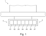
- FIG 1 a part of an extractor hood 1 according to an embodiment of the present invention is shown.
- the extractor hood 1 comprises a viewing screen (not further identified), which is also referred to as a vapor screen or screen, as well as a chimney (also not further identified) extending upwards from the viewing screen.
- a viewing screen (not further identified)
- a chimney also not further identified
- the screen has a flat box shape.
- the front of the screen can be formed by a panel, as described below.
- An operating module 2 is arranged on an underside and on the front area of the extractor hood 1, which has a control panel 3.
- the control panel 3 has a plurality of areas A1-A7.
- the number of areas A1-A7 is not limited to the number shown and can also include fewer or more areas A1-A7, for example only two or three areas A1-A7.
- the arrangement shown is also not limited to a row-like arrangement and it is not absolutely necessary for the areas A1-A7 to be adjacent to one another.
- the areas A1-A7 can be designed as simple buttons, but in this case are designed as capacitive touch sensors. Accordingly, an actuation can be recorded as a change in capacitance and a movement on the surface of the respective areas A1-A7 can be unlimited or unhindered and preferably stepless, depending on the design of the respective touch sensors.
- a specific function of the extractor hood 1 is stored for each button or each area A1-A7, so that a user can set this by operating the respective area A1-A7. It can also be provided that a specific area is provided for switching the control module 2 and/or the extractor hood 1 on and off. Alternatively, this can optionally also be provided by a specific actuation combination and/or actuation method.
- a communicative coupling can be provided, as shown, for example, in the exemplary schematic embodiments according to the Figures 2 and 3
- a switching element 4 can be arranged in the extractor hood 1, as shown in Figure 2 shown.
- the switching element 4 forms an interface for the operating module 2 and is also communicatively connected to a central control and regulating unit 5 of the extractor hood 1.
- the operating module 2 and the control panel 3 can thus communicate with the control and regulating unit 5 via the switching element 4.
- communicative lines (not shown) can be provided between the operating module 2 and the switching element 4, which run over a fastening point of the operating module 2 and are connected to the operating module 2.
- separate lines can also be provided so that the operating module 2 can at least partially communicate directly with the control and regulating unit 5.
- the control and regulating unit 5 is also connected to at least one functional unit 6, so that actuation of the control panel 3 of the operating module via the switching element 4 or the interface and the control and regulating unit 5 causes a function of the extractor hood 1 to be set.
- the control and regulating module 2 can thus be used to control and regulate a light output and/or fan output.
- the operating module 2 is in accordance with Figure 2 is also arranged pivotably on the extractor hood 1 by means of a hinge and is in an unfolded state.
- the control panel 3 is still connected to the control module 2, so that a relative movement between the control panel 3 and the control module 2 does not take place when the pivot position changes.
- the control panel 3 can also be arranged in such a way that a separate positioning of the control panel 3 is possible if the control module 2 is connected to the extractor hood 1, for example, and the control panel 3 is arranged movably on the control module 2.
- the control module 2 In this unfolded state, the control module 2 is in a first operating mode, so that a user can operate specific individual areas of the control panel 3 in order to activate corresponding specific functions of the extractor hood 1.
- the functionality of the control panel 3 and thus also of the control module 2 and the extractor hood 1 is not restricted in the first operating mode and specific functions and/or fine adjustments of the respective functions can be selected as desired.
- the operating module 2 When folded, as in Figure 3 shown, the operating module 2 is in the second operating mode, wherein the functionality is restricted or the functions to be set are at least partially deactivated.
- the control and regulation unit 5 and/or the operating module 2 determine the corresponding change in position of the control panel 3 by means of the changed capacitance value, so that the operating module 2 is accordingly operated in the second operating mode.
- This change in position can be determined under the influence of the switching element 4 or by corresponding elements which are integrated in the hinge 7 and coupled to the switching element 4, for example by an integrated Hall element or two elements which are arranged for relative capacitance measurement.
- control panel 3 In this state, the control panel 3 is not in the user's field of vision and indirect operation of the control panel 3 is still only possible behind a panel 8, which is intended for concealment. Accordingly, in this state or in the second operating mode, targeted selection of individual areas is not possible.
- a predetermined function can be set by non-specific activation of several areas or of two or more areas, for example switching a light function on and off. The user can therefore continue to set basic functions without having to fold out the control panel 3 and/or switch on the control module 2.
- control panel 3 is shown in the first operating mode, whereby the respective areas A1-A7 can be operated and selected in order to set or select a corresponding specific function, as indicated by the continuous white area.
- a single area A4 is operated, as indicated by the hatching. Accordingly, by touching area A4, the user can set a specific function of the extractor hood stored for area A4. Repeatedly operating this area A4 can either fine-tune this function or switch the corresponding function off.
- any individual areas A1-A7 can be operated to set alternative functions or to make adjustments to the selected function.
- control panel 3 or the control module is in the second operating mode, so that the individual specific functions are at least partially and in this case completely deactivated, as indicated by the fine hatching of the areas A1-A3 and A5 to A7.
- actuation of an individual area A4 causes the following: Figure 1 marked with different hatching, no setting of the specific function stored for area A4.
- Such an actuation can therefore be ignored by the operating module or temporarily stored until a sequential actuation, so that, for example, unintentional touches do not result in a setting and manual positioning of the control panel 3 does not trigger or set a function.
- An actuation of several areas in the second operating mode causes a setting of a predetermined function, such as switching on the light with a predetermined intensity.
- a predetermined function such as switching on the light with a predetermined intensity.
- areas A4 and A5 are touched.
- any areas A1-A7 can be selected or operated to set the specified function and it can also be provided that the setting is made when more than two areas A1-A7 are operated. Only one surface operation is required.
- the intensity for example the light intensity, depends on the number of areas A1-A7 operated, depending on the presetting and/or preference of the user.
- two areas A2, A3 can be activated first and a movement and activation sequence to the right can take place, as indicated by the corresponding hatched arrow. Then the areas A3, A4 and finally only area A5 are activated, as shown in the Figures 6B or 6C. Accordingly, the operating module or a control and regulating unit determines a wiping movement to the right. It is irrelevant that at the end of the movement only one area A5 is actuated, especially since several areas were actuated and the sequence of the actuated areas enables the direction of movement to be determined. The wiping movement can be carried out up to the end area of the control panel 3. However, this is not necessary for determining the direction of movement and for setting the specified function.
- FIG. 7A and 7B An alternative wiping motion is available in the Figures 7A and 7B shown.
- areas A6 and A7 are touched or actuated first and then only area A7.
- an actuation duration can be recorded so that a swiping motion can be distinguished from a tapping motion, where the actuation by two fingers does not occur completely simultaneously.
- touch sensors can also be provided in each area A1-A7 so that a more precise actuation sequence can be recorded via the capacitance detection and a better distinction can be made between a static, flat actuation and a short swiping motion.
- control panel 3 comprises further areas B1-B7, which are also arranged in a row and adjacent to each other. Furthermore, the areas B1-B7 border on the areas A1-A7, so that a continuous, two-row touch panel matrix is provided.
- a continuous, two-row touch panel matrix is provided.
- such a matrix is not limited to the number shown in both directions and thus can comprise any number of rows and columns.
- a wiping movement within the columns is also possible.
- the areas A4, A5, A6 and then the areas B4, B5, B6 are activated, so that a touch direction perpendicular to the rows can be detected, as indicated by the corresponding hatched arrow.
- This also makes it possible to set a predetermined function, for example a fan output at a predetermined intensity or level.
- a setting can also be made by activating two areas.
- the flat operation means that at least one predefined function can be set in the second operating mode, so that simple operation and provision of basic functions of the extractor hood is also possible when the operating module and in particular the control panel are not in the field of vision or are indirectly accessible. Furthermore, it is not necessary to switch on the operating module or select a specific function to set the predefined function, so that the user can, for example, easily activate or set a light function even when the extractor hood is switched off, even in poor lighting conditions.
- the different types of operation whereby either static or dynamic operation takes place and/or whereby the number of operated areas can vary, also allow different predefined functions of the extractor hood to be set.
- the number of operated areas for example two or three, or the direction of a wiping movement can therefore correspond to respective, different predefined functions.
- these different types of actuation represent at least partial redundancy in order to further simplify operation.
- the same specified function can be set both for a static actuation of two areas and for three areas and a swipe within the row can be set to the same predefined function as a swipe within a column. In the latter case, an opposite direction can still be detected, for example to switch off the predefined function.
Landscapes
- Engineering & Computer Science (AREA)
- Chemical & Material Sciences (AREA)
- Combustion & Propulsion (AREA)
- Mechanical Engineering (AREA)
- General Engineering & Computer Science (AREA)
- Ventilation (AREA)
- Switches That Are Operated By Magnetic Or Electric Fields (AREA)
Description
Zur Bedienung von Dunstabzugshauben sind Bedieneinheiten bekannt, bei denen einzelne Bedienelemente, insbesondere in Form von Tasten, zum Bedienen unterschiedlicher Funktionseinheiten der Dunstabzugshaube, insbesondere des Lüftergebläses und der Beleuchtungseinrichtung vorgesehen sind. Die Tasten können beispielsweise als Berührungssensoren ausgebildet sein, welche in einem Display integriert sind. Dabei kann für jede Taste eine spezifische Funktion hinterlegt sein, sodass die Funktion durch manuelle Betätigung der jeweiligen Taste beziehungsweise des Berührungssensors eingestellt werden kann. Zur vereinfachten Bedienung und Einstellung sind die entsprechenden Funktionen für die jeweiligen Tasten in der Regel mit aufgedruckten Symbolen gekennzeichnet und sind solche Bedienteile weiterhin generell im Sichtbereich des Benutzers angeordnet, beispielsweise an einer Vorderseite der Dunstabzugshaube.Control units are known for operating extractor hoods in which individual control elements, in particular in the form of buttons, are provided for operating different functional units of the extractor hood, in particular the fan and the lighting device. The buttons can, for example, be designed as touch sensors which are integrated in a display. A specific function can be stored for each button so that the function can be set by manually pressing the respective button or the touch sensor. To simplify operation and setting, the corresponding functions for the respective buttons are usually marked with printed symbols and such control elements are also generally arranged in the user's field of vision, for example on the front of the extractor hood.
Die Anordnung im Sichtbereich des Benutzers hat jedoch nicht nur eine Auswirkung auf das Erscheinungsbild und der Akzeptanz der Dunstabzugshaube, sondern kann den Benutzer ebenfalls bei der weiteren Arbeit unter der Dunstabzugshaube beeinträchtigen, sodass das Bedienteil bevorzugt nach dem Einstellen oder auch nach dem Betrieb der Dunstabzugshaube außerhalb des Sichtbereichs des Benutzers angeordnet ist.However, the arrangement in the user's field of vision not only affects the appearance and acceptance of the extractor hood, but can also impair the user's further work under the extractor hood, so that the control unit is preferably arranged outside the user's field of vision after adjustment or even after operation of the extractor hood.
Bei einer solchen Anordnung außerhalb des Sichtbereiches ist eine selektive beziehungsweise spezifische Auswahl und Einstellung der jeweiligen Funktionen jedoch nicht möglich, sodass das Bedienteil zum Verhindern von fehlerhaften oder unbeabsichtigten Einstellungen ausgeschaltet ist und wieder in den Sichtbereich angeordnet werden muss, um eine weitere Einstellung einer Funktion zu ermöglichen. Weiterhin ist für das Einstellen der Funktionen, unabhängig von der Anordnung des Bedienteils, zunächst ein Einschalten des Bedienteils vorgesehen. Solche Bedienungsvorgänge werden vom jeweiligen Benutzer als umständlich und wenig intuitiv empfunden, insbesondere, wenn einfache Funktionen wie eine Bedienung des Lichts beispielsweise bei schwachen Lichtverhältnissen eingestellt werden sollen.However, with such an arrangement outside the field of vision, a selective or specific selection and setting of the respective functions is not possible, so the control unit is switched off to prevent incorrect or unintentional settings and must be placed back in the field of vision to enable further setting of a function. Furthermore, to set the functions, regardless of the arrangement of the control unit, the control unit must first be switched on. Such operating processes are perceived by the respective user as cumbersome and not very intuitive, especially when simple functions such as operating the light, for example, have to be set in low light conditions.
Aus
Aufgabe der vorliegenden Erfindung ist es daher eine Dunstabzugshaube zu schaffen, die eine vereinfachte Bedienung und Einstellung von Funktionen der Dunstabzugshaube ermöglicht.The object of the present invention is therefore to provide an extractor hood which enables simplified operation and adjustment of functions of the extractor hood.
Diese Aufgabe wird erfindungsgemäß durch eine Dunstabzugshaube nach Anspruch 1 gelöst, welche ein Bedienmodul umfasst, wobei das Bedienmodul ein Bedienfeld zum Einstellen von Funktionen der mit dem Bedienmodul gekoppelten Dunstabzugshaube umfasst. Das Bedienfeld weist mindestens zwei Bereiche auf und das Bedienmodul ist dazu eingerichtet, in einem ersten Betriebsmodus des Bedienmoduls und bei Betätigung eines spezifischen Bereichs mindestens eine jeweilige spezifische Funktion der Dunstabzugshaube einzustellen. Die Dunstabzugshaube ist dadurch gekennzeichnet, dass das Bedienmodul weiterhin in einem zweiten Betriebsmodus betreibbar ist, wobei das Bedienmodul dazu eingerichtet ist, im zweiten Betriebsmodus und bei Betätigung von mindestens zwei Bereichen mindestens eine vorgegebene Funktion der gekoppelten Dunstabzugshaube einzustellen.This object is achieved according to the invention by an extractor hood according to
Das Bedienmodul kann in der Dunstabzugshaube integriert oder als separates Teil mit der Dunstabzugshaube verbunden sein. Somit kann das Bedienmodul beispielsweise im Gehäuse der Dunstabzugshaube, das auch als Chassis der Dunstabzugshaube bezeichnet werden kann, angeordnet oder auch in einer Aufnahme des Gehäuses der Dunstabzugshaube, beispielsweise an der unteren und/oder einer vorderen beziehungsweise seitlichen Oberfläche der Dunstabzugshaube, aufgenommen sein. Dabei ist das Bedienmodul mit den für die Funktionen erforderlichen jeweiligen Komponenten kommunikativ gekoppelt, sodass über das Bedienfeld des Bedienmoduls die Funktionen der Dunstabzugshaube eingestellt werden können. Das Bedienmodul kann somit als modulare Einheit ausgebildet sein, welche standardmäßig in der Dunstabzugshaube eingebaut ist oder zur Nachrüstung mit der Dunstabzugshaube gekoppelt werden kann.The control module can be integrated into the extractor hood or connected to the extractor hood as a separate part. The control module can therefore be arranged in the housing of the extractor hood, which can also be referred to as the chassis of the extractor hood, for example, or it can be accommodated in a receptacle in the housing of the extractor hood, for example on the lower and/or a front or side surface of the extractor hood. The control module is communicatively coupled with the respective components required for the functions, so that the functions of the extractor hood can be set via the control panel of the control module. The control module can therefore be designed as a modular unit which is built into the extractor hood as standard or can be coupled to the extractor hood for retrofitting.
Das Bedienfeld definiert einen Abschnitt des Bedienmoduls womit die spezifischen Funktionen eingestellt werden können. Die verschiedenen Bereiche können beispielsweise als entsprechend gekennzeichnete Tasten ausgebildet sein, wobei durch Betätigung der Tasten ein Signal, beispielsweise ein elektromechanisches Signal, erzeugt wird, welches für die jeweilige Funktion spezifisch ist. Somit ist durch eine manuelle Betätigung beziehungsweise Berührung einzelner Bereiche eine Einstellung der jeweiligen Funktionen bereitgestellt. Anstatt einer manueller Eingabe kann jedoch ebenfalls ein Stift oder ähnliche Vorrichtung vorgesehen sein, um eine Berührung der jeweiligen Bereiche und Einstellung der entsprechenden Funktionen zu ermöglichen.The control panel defines a section of the control module with which the specific functions can be set. The different areas can, for example, be designed as correspondingly marked buttons, whereby pressing the buttons generates a signal, for example an electromechanical signal, which is specific to the respective function. This means that a manual By activating or touching individual areas, the respective functions can be set. Instead of manual input, however, a pen or similar device can also be provided to enable the respective areas to be touched and the corresponding functions to be set.
Unter Funktionen der Dunstabzugshaube sind insbesondere das Ansaugen von Luft, Dünsten und Wrasen aus einem Raum unterhalb der Dunstabzugshaube sowie die Beleuchtung eines Raums, insbesondere unterhalb der Dunstabzugshaube zu verstehen. Die Funktion kann weiterhin einen bestimmten Betriebszustand umfassen, gegebenenfalls unter vorgegebenen beziehungsweise spezifischen Betriebsbedingungen.The functions of the extractor hood include in particular the intake of air, fumes and vapors from a room below the extractor hood as well as the lighting of a room, in particular below the extractor hood. The function can also include a certain operating state, possibly under predetermined or specific operating conditions.
So kann zumindest eine Funktion der Dunstabzugshaube zumindest zeitweise ausgeführt werden und somit einen Betriebszustand definieren. Beispielsweise kann eine Normallüftung ausgeführt werden, bei der eine Lüfterstufe in der Regel von dem Benutzer gewählt oder festgelegt wird. Ein weiterer Betriebszustand ist die Intervalllüftung, bei der das Lüftergebläse nur in zeitlich beabstandeten Intervallen betrieben wird. Auch die Nachlüftung stellt einen Betriebszustand der Dunstabzugshaube dar. Hierbei wird das Lüftergebläse nach Ausschalten der Dunstabzugshaube noch für eine vorgegebene Zeitspanne weiter betrieben. Bei dem Betriebszustand der Automatiklüftung wird die Lüfterleistung oder Lüfterstufe durch Sensorsignale festgelegt, die beispielsweise durch einen Ultraschallsensor erfasst wurden.In this way, at least one function of the extractor hood can be carried out at least temporarily, thus defining an operating state. For example, normal ventilation can be carried out, in which a fan level is usually selected or set by the user. Another operating state is interval ventilation, in which the fan blower is only operated at spaced intervals. Post-ventilation is also an operating state of the extractor hood. Here, the fan blower continues to operate for a specified period of time after the extractor hood has been switched off. In the automatic ventilation operating state, the fan power or fan level is determined by sensor signals that have been recorded by an ultrasonic sensor, for example.
Die genannten Betriebszustände der Dunstabzugshaube betreffen alle die Funktion der Dunstabzugshaube des Ansaugens von Luft, Wrasen und Dünsten. Allerdings kann die Dunstabzugshaube auch in einen weiteren Betriebszustand gebracht werden, bei dem durch die Beleuchtungseinrichtung ein Raum oder eine Fläche ausgeleuchtet wird. Die unterschiedlichen Betriebszustände der Dunstabzugshaube, die das Ansaugen von Luft, Wrasen und Dünsten betreffen, sowie der Betriebszustand des Beleuchtens können auch in Kombination miteinander eingestellt werden, wobei zum Einstellen der spezifischen Funktion der jeweilige einzelne Bereich des Bedienmoduls, gegebenenfalls mehrmals, betätigt werden muss.The above-mentioned operating states of the extractor hood all relate to the function of the extractor hood for sucking in air, vapors and fumes. However, the extractor hood can also be put into another operating state in which a room or area is illuminated by the lighting device. The different operating states of the extractor hood, which relate to sucking in air, vapors and fumes, as well as the operating state of the lighting can also be set in combination with one another, whereby the respective individual area of the control module must be operated, possibly several times, to set the specific function.
Weiterhin können für jeden Betriebszustand mehrere Betriebsbedingungen bestehen, die insbesondere die Dauer und Intensität der von der Dunstabzugshaube in diesemFurthermore, for each operating state, several operating conditions can exist, which in particular determine the duration and intensity of the heat generated by the extractor hood in this
Betriebszustand auszuführenden Funktion beschreiben. Die Betriebsbedingungen sind somit insbesondere die Intensität der Lüfterleistung und/oder der Beleuchtung, die Dauer der Lüftung und/oder der Beleuchtung, die Zeitpunkte der Lüftung und/oder der Beleuchtung, die Erzeugung von Sensorsignalen durch Sensoren sowie Programme, die die Betriebsbedingungen der weiteren Funktionseinheiten einstellen.Describe the function to be carried out in the operating state. The operating conditions are therefore in particular the intensity of the fan power and/or the lighting, the duration of the ventilation and/or lighting, the times of the ventilation and/or lighting, the generation of sensor signals by sensors and programs that set the operating conditions of the other functional units.
Um fehlerhafte oder versehentliche Einstellungen weitestgehend zu verhindern, ist das Bedienmodul dazu eingerichtet den Betriebsmodus des Bedienmoduls, der im Folgenden der Einfachheit halber nur als Betriebsmodus bezeichnet wird, zu bestimmen und die Funktionen in Abhängigkeit des Betriebsmodus zu ermöglichen. So kann in einem ersten Betriebsmodus, wie vorstehend beschrieben, eine spezifische Funktion durch Betätigung eines einzelnen Bereichs des Bedienfelds eingestellt werden. Mit anderen Worten kann der Benutzer beispielsweise einen bestimmten Betriebszustand des Lüfters durch Betätigung einer entsprechenden Taste einstellen. Es kann zusätzlich vorgesehen sein, dass im ersten Betriebsmodus spezifische Betriebszustände oder Kombinationen von Funktionen durch Betätigung von mehreren Bereichen erfolgt.In order to prevent incorrect or accidental settings as far as possible, the operating module is designed to determine the operating mode of the operating module, which for the sake of simplicity is referred to below as the operating mode, and to enable the functions depending on the operating mode. In a first operating mode, as described above, a specific function can be set by operating a single area of the control panel. In other words, the user can, for example, set a specific operating state of the fan by pressing a corresponding button. It can also be provided that in the first operating mode, specific operating states or combinations of functions occur by operating several areas.
Im zweiten Betriebsmodus wird eine Funktion dahingegen nur bei Betätigung von mindestens zwei Bereichen eingestellt, sodass eine Betätigung eines einzelnen Bereichs keine Einstellung bewirkt. Dies hat den Vorteil, dass durch eine versehentliche Berührung eines einzelnen spezifischen Bereichs im zweiten Betriebsmodus keine unerwünschte Einstellung einer entsprechenden spezifischen Funktion bewirkt. So kann beispielsweise bei schwächeren Lichtverhältnissen eine gezielte Betätigung erschwert sein, sodass anstatt einer Betätigung eines Bereichs, welcher für die Lichteinstellung spezifisch ist, ein Bereich betätigt werden kann, welcher für die Lüftereinstellung spezifisch ist. In solchen Fällen ist es vorteilhaft, dass der Lüfter beziehungsweise die Lüftereinstellungen nicht angepasst werden und der Benutzer somit keine versehentlichen Einstellungen von Funktionen zunächst rückgängig machen muss oder auch mehrere Versuche braucht, um die erwünschte Funktion einzustellen.In the second operating mode, however, a function is only set when at least two areas are activated, so that activation of a single area does not result in a setting. This has the advantage that accidentally touching a single specific area in the second operating mode does not result in an undesired setting of a corresponding specific function. For example, in poor lighting conditions, targeted activation can be more difficult, so that instead of activating an area that is specific to the light setting, an area that is specific to the fan setting can be activated. In such cases, it is advantageous that the fan or the fan settings do not need to be adjusted, meaning that the user does not have to first undo accidental function settings or need several attempts to set the desired function.
Weiterhin ist die Funktion im zweiten Betriebsmodus, im Gegensatz zum ersten Betriebsmodus, nicht spezifisch, sondern vorgegeben. Somit können einfache Grundfunktionen durch die Betätigung von mehreren Bereichen auch im zweiten Betriebsmodus eingestellt werden.Furthermore, the function in the second operating mode, unlike the first operating mode, is not specific but predetermined. This means that simple basic functions can also be set in the second operating mode by activating several areas.
Die vorgegebene Funktion im zweiten Betriebsmodus umfasst bevorzugt das Ein- und Ausschalten des Lichts und/oder der Lüftung, bevorzugt bei einer vorgegebenen Intensität. Beispielsweise kann durch Betätigung von mindestens zwei Bereichen eine voreingestellte Lichtintensität mindestens einer Lichtquelle der Dunstabzugshaube und/oder eine vorgegebene Lüfterintensität eingestellt werden. Somit kann der Benutzer unter verschiedenen Bedingungen bestimmte Funktionen der Dunstabzugshaube abrufen, beispielsweise um für eine Raumatmosphäre oder Stimmung nur eine vorgegebene beziehungsweise voreingestellte Lichtfunktion zu ermöglichen oder um den Lüfter mit einem vorgegebenen Betriebszustand beziehungsweise einer vorgegebenen Betriebsbedingung einzuschalten, wenn beispielsweise keine besondere Einstellung des Betriebszustands erforderlich und ein Standardprogramm für die Arbeit unter der Dunstabzugshaube ausreichend ist.The predefined function in the second operating mode preferably includes switching the light and/or ventilation on and off, preferably at a predefined intensity. For example, by activating at least two areas, a preset light intensity of at least one light source of the extractor hood and/or a predefined fan intensity can be set. The user can thus call up certain functions of the extractor hood under different conditions, for example to only enable a predefined or preset light function for a room atmosphere or mood or to switch the fan on with a predefined operating state or a predefined operating condition, for example if no special setting of the operating state is required and a standard program for working under the extractor hood is sufficient.
Bevorzugt ist der erste Betriebsmodus ein Normalbetrieb zum Einstellen der jeweiligen spezifischen Funktionen der gekoppelten Dunstabzugshaube und die Funktionen sind im zweiten Betriebsmodus zumindest teilweise deaktiviert. Mit anderen Worten kann der erste Betriebsmodus eine aktive und spezifische Einstellung der verschiedenen Funktionen ermöglichen, während diese Möglichkeit im zweiten Betriebsmodus zumindest teilweise nicht vorhanden ist. So kann der erste Betriebsmodus einem eingeschalteten Zustand des Bedienmoduls entsprechen und der zweite Betriebsmodus beispielsweise ein Ruhezustand, ausgeschalteter Zustand, Stand-By-Modus oder Stromsparmodus des Bedienmoduls und gegebenenfalls der Dunstabzugshaube sein.Preferably, the first operating mode is a normal operation for setting the respective specific functions of the coupled extractor hood and the functions are at least partially deactivated in the second operating mode. In other words, the first operating mode can enable an active and specific setting of the various functions, while this option is at least partially not available in the second operating mode. The first operating mode can correspond to a switched-on state of the operating module and the second operating mode can be, for example, a rest state, switched-off state, stand-by mode or power-saving mode of the operating module and, if applicable, the extractor hood.
Das Bereitstellen einer vorgegebenen Funktion im zweiten Betriebsmodus hat somit weiterhin den Vorteil, dass ein Einschalten beziehungsweise Aktivieren des Bedienmoduls nicht erforderlich ist, um bestimmte Funktionen der Dunstabzugshaube zu ermöglichen. Das Bedienmodul kann somit weiterhin im zweiten Betriebsmodus betrieben werden, wobei beispielsweise eine Lichtfunktion als Grundfunktion dennoch ermöglicht wird. Dadurch wird die Bedienung für den Benutzer erheblich vereinfacht, zumal der Benutzer weder eine Einschalttaste noch einen spezifischen Bereich betätigen muss und einfach durch Berührung von mindestens zwei Bereichen eine vorgegebene Funktion einstellen kann.Providing a predefined function in the second operating mode therefore has the further advantage that it is not necessary to switch on or activate the control module in order to enable certain functions of the extractor hood. The control module can therefore continue to be operated in the second operating mode, whereby, for example, a light function is still enabled as a basic function. This makes operation much easier for the user, especially since the user does not have to press a power button or a specific area and can simply set a predefined function by touching at least two areas.
Durch das Vorsehen von zwei Bereichen sind bereits mehrere vorgegebene Funktionen einstellbar beziehungsweise kann zwischen mehreren vorgegebenen Funktionen unterschieden werden, beispielsweise anhand einer erfassten unterschiedlichen Betätigungsdauer oder anhand eines erfassten unterschiedlichen Betätigungsdrucks. Ebenfalls können die Bereiche beziehungsweise die Tasten des Bedienfelds voneinander beanstandet sein. Bevorzugt umfasst das Bedienfeld jedoch mindestens drei Bereiche, welche in Reihe und angrenzend zueinander angeordnet sind. Zwei oder mehr Bereiche können ebenfalls in mehreren, aneinander angrenzenden Reihen angeordnet sein, sodass die Bereiche sowohl nebeneinander als auch übereinander angeordnet sind bzw. eine Matrix bilden. Das Bedienmodul kann dabei dazu eingerichtet sein, die vorgegebene Funktion im zweiten Betriebsmodus unabhängig von den jeweiligen für den ersten Betriebsmodus spezifischen Funktionen der betätigten Bereiche einzustellen.By providing two areas, several predefined functions can be set or a distinction can be made between several predefined functions, for example based on a recorded different actuation duration or based on a recorded different actuation pressure. The areas or the buttons of the control panel can also be spaced apart from one another. However, the control panel preferably comprises at least three areas which are arranged in a row and adjacent to one another. Two or more areas can also be arranged in several adjacent rows so that the areas are arranged both next to one another and one above the other or form a matrix. The operating module can be set up to set the predefined function in the second operating mode independently of the respective functions of the actuated areas specific to the first operating mode.
Entsprechend kann der Benutzer, auch wenn eine Vielzahl von Bereichen beziehungsweise Tasten zum Einstellen von spezifischen Funktionen im ersten Betriebsmodus vorgesehen sind, zwei beliebige Bereiche betätigen, um die vorgegebene Funktion einzustellen. Mit anderen Worten ist die Betätigung im zweiten Betriebsmodus unspezifisch und das Einstellen der vorgegebenen Funktion kann mithin bei jeder Kombination zweier Bereiche erfolgen. Die reihenförmige und angrenzende Anordnung hat dabei weiterhin den Vorteil, dass die Bereiche sich direkt nebeneinander befinden und eine Betätigung von mindestens zwei Bereichen durch den Benutzer somit vereinfacht wird, insbesondere bei schwächeren Lichtverhältnissen oder wenn das Bedienfeld schwer oder nur indirekt zugänglich ist.Accordingly, even if a large number of areas or buttons are provided for setting specific functions in the first operating mode, the user can operate any two areas to set the specified function. In other words, the operation in the second operating mode is non-specific and the specified function can therefore be set in any combination of two areas. The row-like and adjacent arrangement also has the advantage that the areas are located directly next to each other, making it easier for the user to operate at least two areas, particularly in poor lighting conditions or when the control panel is difficult or only indirectly accessible.
Das Bedienmodul kann weiterhin dazu eingerichtet sein, die vorgegebene Funktion in Abhängigkeit von einer erfassten Anzahl der betätigten Bereiche, einer erfassten Abfolge der betätigten Bereiche, einer erfassten Geschwindigkeit einer Abfolge der betätigten Bereiche, einer bestimmten Betätigungsrichtung, und/oder einer erfassten Betätigungsdauer einzustellen.The operating module can further be configured to set the predetermined function depending on a detected number of actuated areas, a detected sequence of actuated areas, a detected speed of a sequence of actuated areas, a specific actuation direction, and/or a detected actuation duration.
Auf diese Weise können, wie vorstehend beschrieben, unterschiedliche vorgegebene Funktionen beispielsweise durch eine vom Bedienmodul erfasste unterschiedliche Betätigungsdauer eingestellt werden. Es kann zusätzlich oder alternativ ebenfalls vorgesehen sein, dass mehr als zwei Bereiche betätigt werden, beispielsweise wenn der Benutzer anstatt einer Berührung mit zwei Fingern das Bedienfeld mit drei oder mehr Fingern betätigt, wobei bei einer Betätigung von zwei Bereichen beispielsweise eine vorgegebene Lichteinstellung und bei Betätigung von drei oder mehr Bereichen beispielsweise eine vorgegebene Lüfterintensität eingestellt wird.In this way, as described above, different predefined functions can be set, for example by a different actuation duration recorded by the operating module. In addition or alternatively, it can also be provided that more than two areas are actuated, for example when the Users operate the control panel with three or more fingers instead of touching it with two fingers, whereby an operation of two areas sets a predefined light setting, for example, and an operation of three or more areas sets a predefined fan intensity, for example.
Weiterhin kann zum Einstellen einer vorgegebenen Funktion eine gleichzeitige Betätigung der Bereiche erforderlich sein. Eine vorgegebene Funktion kann zusätzlich oder alternativ auch durch eine Betätigungsabfolge mehrerer Bereiche eingestellt werden. So kann zunächst ein einzelner erster Bereich und anschließend ein benachbarter beziehungsweise angrenzender zweiter Bereich betätigt werden, wobei der erste Bereich nicht mehr betätigt bzw. berührt wird. Das Bedienmodul ist dabei bevorzugt dazu eingerichtet, eine zeitliche Komponente der Betätigung zu erfassen, sodass beispielsweise durch eine Betätigungsdauer der jeweiligen Bereiche und/oder ein zeitliches Intervall zwischen der Betätigung der jeweiligen Bereiche zwischen einer gezielten Betätigung mehrerer Bereiche, einer sequenziellen Betätigung oder einer versehentlichen Betätigung unterschieden werden kann.Furthermore, simultaneous activation of the areas may be necessary to set a given function. A given function can also be set additionally or alternatively by activating several areas in sequence. For example, a single first area can be activated first and then an adjacent or adjacent second area, with the first area no longer being activated or touched. The operating module is preferably set up to record a temporal component of the activation, so that, for example, a distinction can be made between a targeted activation of several areas, a sequential activation or an accidental activation based on the duration of activation of the respective areas and/or a time interval between the activation of the respective areas.
Bei einer sequenziellen Betätigung kann weiterhin eine Betätigungsrichtung erfasst werden, welche für eine vorgegebene Funktion der Dunstabzugshaube kennzeichnend ist. Bei der sequenziellen Betätigung können in jedem Zustand jeweils ein einzelner Bereich oder mehrere angrenzende Bereiche betätigt sein, sodass beispielsweise eine Wischbewegung mit einem Finger oder mit zwei Fingern des Benutzers erfasst beziehungsweise bestimmt werden kann. Eine Wischbewegung kann somit weiterhin an den Endbereichen des Bedienfelds erfasst werden, wenn beispielsweise zunächst die äußeren zwei Bereiche an einem Ende des Bedienfelds und anschließend nur der äußerste Bereich betätigt werden, wobei dies bevorzugt in Abhängigkeit einer Betätigungsdauer erfasst wird.With sequential actuation, an actuation direction can also be detected, which is characteristic of a given function of the extractor hood. With sequential actuation, a single area or several adjacent areas can be actuated in each state, so that, for example, a wiping movement with one finger or with two fingers of the user can be detected or determined. A wiping movement can therefore still be detected at the end areas of the control panel if, for example, the outer two areas at one end of the control panel are actuated first and then only the outermost area, whereby this is preferably detected depending on the duration of the actuation.
Für den Benutzer werden somit verschiedene Möglichkeiten zum Einstellen der vorgegebenen Funktion oder auch einer Vielzahl von unterschiedlichen vorgegebene Funktionen bereitgestellt. Vorteilhaft ist dabei, dass hierzu nahezu das vollständige Bedienfeld verwendet werden kann und der Benutzer einfache Grundfunktionen der Dunstabzugshaube ohne gezielte Auswahl oder umständliche Bedienung einstellen kann. Obwohl durch die oben genannte Betätigungsdauer und Betätigungsabfolge eine Vielzahl von Funktionen ermöglicht werden, können solche unterschiedliche Betätigungen ebenfalls eine gewisse Redundanz darstellen, sodass der Benutzer sich beim Einstellen der vorgegebenen Funktion im zweiten Betriebsmodus keine Gedanken über die erforderliche Betätigung machen muss.This provides the user with various options for setting the specified function or a variety of different specified functions. The advantage here is that almost the entire control panel can be used for this purpose and the user can set simple basic functions of the extractor hood without specific selection or complicated operation. Although the above-mentioned operating duration and operating sequence allow a variety of of functions, such different operations can also provide a certain degree of redundancy so that the user does not have to worry about the required operation when setting the predetermined function in the second operating mode.
Das Bedienmodul ist weiter bevorzugt dazu eingerichtet, für eine statische Betätigung und eine dynamische Betätigung unterschiedliche vorgegebene Funktionen einzustellen. Mit anderen Worten kann das Bedienmodul zwischen einer flächigen Betätigung ohne Abfolge und einer sequenziellen Betätigung und somit beispielsweise zwischen dem Aufliegen und einer Wischbewegung von Fingerspitzen unterscheiden. Bei einer flächigen, statischen Betätigung kann zum Beispiel vorgesehen sein, dass eine voreingestellt beziehungsweise vorgegebene Lichtintensität einer Lichtquelle eingeschaltet wird, während eine Wischbewegung das Einstellen einer vorgegebenen Lüfterintensität bewirkt. Durch eine wiederholte entsprechende Betätigung kann die jeweilige Funktion ebenfalls wieder ausgeschaltet werden, wobei das Ein- und Ausschalten bei einer Wischbewegung optional von einer erfassten Betätigungsrichtung abhängig sein kann.The operating module is further preferably designed to set different predefined functions for static actuation and dynamic actuation. In other words, the operating module can distinguish between a flat actuation without sequence and a sequential actuation and thus, for example, between resting on the surface and a swiping motion of fingertips. In the case of a flat, static actuation, it can be provided, for example, that a preset or predefined light intensity of a light source is switched on, while a swiping motion sets a predefined fan intensity. The respective function can also be switched off again by repeated corresponding actuation, whereby switching on and off during a swiping motion can optionally be dependent on a detected actuation direction.
Um eine verbesserte Trennung zwischen dem ersten und zweiten Betriebsmodus bereitzustellen, kann das Bedienmodul weiterhin dazu eingerichtet sein, im ersten Betriebsmodus eine spezifische Funktion nur bei Betätigung eines einzelnen spezifischen Bereichs einzustellen. Zudem kann das Bedienmodul nach einer vorgegebenen Zeit, in der keine Einstellung vorgenommen wird, automatisch in den zweiten Betriebsmodus wechseln, wobei dann nur bestimmte vorgegebene Funktionen auswählbar beziehungsweise einstellbar sind.In order to provide an improved separation between the first and second operating modes, the operating module can further be configured to set a specific function in the first operating mode only when a single specific area is actuated. In addition, the operating module can automatically switch to the second operating mode after a predetermined time in which no setting is made, in which case only certain predetermined functions can be selected or set.
Ebenfalls kann in einer solchen Konfiguration beziehungsweise Ausgestaltung vorgesehen sein, dass die im zweiten Betriebsmodus vorgesehene vorgegebene Funktion ebenfalls durch Betätigung mehrerer Bereiche im ersten Betriebsmodus einstellbar ist. So kann beispielsweise, wenn das Bedienmodul automatisch in den zweiten Betriebsmodus wechselt, eine Bedienung des Lichts und/oder der Lüfterintensität einfach vorgenommen werden, ohne dass Bedienmodul in den ersten Betriebsmodus zu schalten und eine selektive, spezifische Auswahl des jeweiligen Bereichs zu treffen.In such a configuration or design, it can also be provided that the predetermined function provided in the second operating mode can also be set by operating several areas in the first operating mode. For example, if the operating module automatically switches to the second operating mode, the light and/or the fan intensity can be easily operated without switching the operating module to the first operating mode and making a selective, specific selection of the respective area.
Zum Integrieren des Bedienmoduls in der Dunstabzugshaube kann eine kommunikative Kopplung vorgesehen sein. Bevorzugt umfasst das Bedienmodul zum Erfassen einer Betätigung der Bereiche und zum Einstellen der Funktionen eine mit dem Bedienfeld kommunikativ gekoppelte Steuer- und Regeleinheit oder eine Schnittstelle zum kommunikativen Koppeln des Bedienfelds mit einer Steuer- und Regeleinheit der Dunstabzugshaube. Die Steuer- und Regeleinheit kann somit zumindest teilweise ausgelagert sein, sodass die Komplexität des Bedienmoduls geringgehalten werden kann. Das Bedienmodul kann in einem solchen Fall am Bedienfeld erfasste elektrische Signale zur Verarbeitung und zum Steuern/Regeln einer Funktionseinheit der Dunstabzugshaube an eine zentrale Steuer- und Regeleinheit über eine entsprechende Schnittstelle übertragen. Beispielsweise kann die Verbindung zwischen dem Bedienmodul und der Lüftergebläseeinheit und der Beleuchtungseinheit über eine solche Steuereinheit bestehen, wobei die Steuereinheit hierbei eine zentrale Dunstabzugshaubensteuerung oder eine spezifische Lüftersteuerung und eine spezifische Beleuchtungssteuerung sein kann.A communicative coupling can be provided for integrating the operating module in the extractor hood. The operating module preferably comprises a control and regulating unit communicatively coupled to the control panel or an interface for communicatively coupling the control panel to a control and regulating unit of the extractor hood for detecting an actuation of the areas and for setting the functions. The control and regulating unit can thus be at least partially outsourced so that the complexity of the operating module can be kept low. In such a case, the operating module can transmit electrical signals detected on the control panel to a central control and regulating unit via a corresponding interface for processing and controlling/regulating a functional unit of the extractor hood. For example, the connection between the operating module and the fan blower unit and the lighting unit can be via such a control unit, whereby the control unit can be a central extractor hood control or a specific fan control and a specific lighting control.
Alternativ kann das Bedienmodul jedoch ebenfalls die zum Auswerten der erfassten Betätigung vorgesehene Steuer- und Regeleinheit umfassen, sodass beispielsweise lediglich eine Schnittstelle vorgesehen sein kann, welche mit einer oder mehreren Funktionseinheiten gekoppelt werden kann, um eine direkte Einstellung der jeweiligen Funktion zu ermöglichen. Auf diese Weise kann das Bedienmodul ebenfalls einfach zum Nachrüsten beziehungsweise Austauschen von bestehenden Bedienmodulen ausgebildet sein.Alternatively, the operating module can also include the control and regulation unit intended for evaluating the recorded actuation, so that, for example, only one interface can be provided, which can be coupled to one or more functional units in order to enable direct setting of the respective function. In this way, the operating module can also be designed to easily retrofit or replace existing operating modules.
Die Verbindung zwischen dem Bedienmodul und einer Funktionseinheit kann somit unmittelbar oder mittelbar, das heißt über weitere Einheiten oder Komponenten bestehen. Die Verbindung kann zudem mechanisch durch Drähte oder andere Signalübertragungsmittel oder elektronisch durch Schaltungen gebildet sein.The connection between the operating module and a functional unit can therefore be direct or indirect, i.e. via other units or components. The connection can also be formed mechanically by wires or other signal transmission means or electronically by circuits.
Obwohl die Betätigung der Bereiche mittels Tasten erfolgen kann, umfasst jeder Bereich bevorzugt eine oder mehrere kapazitive Berührungssensoren, wobei das Bedienfeld bevorzugt als Berührungsfeldmatrix ausgebildet ist. Entsprechend wird eine flächige Betätigung, insbesondere durch eine durchgehende und unbegrenzte Erfassung, vereinfacht.Although the areas can be operated using buttons, each area preferably comprises one or more capacitive touch sensors, with the control panel preferably being designed as a touch panel matrix. Accordingly, surface-level operation is simplified, in particular through continuous and unlimited detection.
Weiterhin ist hierdurch eine Wischbewegung leichter auszuführen und zu erfassen und es kann anhand der Kapazitätsänderung ebenfalls eine höhere Erfassungsgenauigkeit bereitgestellt werden, sodass ebenfalls leichter zwischen einer gewollten flächigen und dynamischen Betätigung unterschieden werden kann. Hierdurch wird die Bedienung erheblich vereinfacht und das Erfassen von fehlerhaften und/oder unbeabsichtigten Betätigungen reduziert. Weiterhin bietet eine solche Ausgestaltung eine intuitive Bedienungsmöglichkeit während gleichzeitig eine vereinfachte Reinigung des Bedienfelds ermöglicht wird.Furthermore, this makes it easier to carry out and record a wiping movement and the change in capacitance can also provide greater detection accuracy, making it easier to distinguish between an intentional flat and dynamic actuation. This makes operation much easier and reduces the detection of incorrect and/or unintentional actuations. Furthermore, such a design offers an intuitive operating option while at the same time making it easier to clean the control panel.
Zum Wechseln der Betriebsmodi kann das Bedienmodul dazu eingerichtet sein, den Betriebsmodus durch Ein- und Ausschalten und/oder durch Ändern der Position des Bedienfelds zwischen einer ersten und zweiten Position zu wechseln.To change the operating modes, the operating module can be configured to change the operating mode by switching on and off and/or by changing the position of the control panel between a first and second position.
Das Bedienmodul kann somit beispielsweise ausgeschaltet werden, wenn die Dunstabzugshaube ausgeschaltet oder wenn lediglich die Einstellung der jeweiligen spezifischen Funktionen eingeschränkt werden soll. Die Position des Bedienfelds kann dabei unverändert bleiben.The control module can therefore be switched off, for example, when the extractor hood is to be switched off or when the setting of the specific functions is to be restricted. The position of the control panel can remain unchanged.
Ein Wechseln des Betriebsmodus durch Ändern der Position des Bedienfelds hat den Vorteil, dass das Bedienfeld im zweiten Betriebsmodus außerhalb des Sichtbereichs angeordnet sein kann. Obwohl das Bedienmodul und gegebenenfalls die Dunstabzugshaube sich dabei in einem ausgeschalteten Zustand befinden können, können die bereits eingestellten Funktionen ebenfalls beibehalten bleiben, sodass ein weiterer Betrieb der Dunstabzugshaube möglich ist. Im zweiten Betriebsmodus kann jedoch keine gezielte Bedienung vorgenommen werden, sodass die einzustellenden Funktionen zumindest teilweise eingeschränkt sind und beispielsweise eine Feineinstellung der Lichtintensität oder der Lüfterintensität nicht ermöglicht wird. Es sind aber weiterhin Grundfunktionen über die vorgegebene Funktion durch Betätigung mehrerer Bereiche wählbar bzw. ein Schaltbar.Changing the operating mode by changing the position of the control panel has the advantage that the control panel can be positioned out of sight in the second operating mode. Although the control module and, if applicable, the extractor hood can be switched off, the functions that have already been set can also be retained so that the extractor hood can continue to be operated. However, no targeted operation can be carried out in the second operating mode, so that the functions that can be set are at least partially restricted and, for example, fine adjustment of the light intensity or the fan intensity is not possible. However, basic functions can still be selected or switched via the predefined function by operating several areas.
Bevorzugt ist das Bedienfeld zum Ändern der Position schwenkbar oder schiebbar an einem Gehäuse des Bedienmoduls oder an einem Gehäuse der Dunstabzugshaube angeordnet, wobei das Bedienfeld bevorzugt in der ersten Position von dem Gehäuse des Bedienmoduls und/oder der Dunstabzugshaube herausragt und in der zweiten Position im Wesentlichen mit mindestens einer äußeren Oberfläche des Gehäuses fluchtet.Preferably, the control panel is arranged so as to be pivotable or sliding on a housing of the control module or on a housing of the extractor hood in order to change the position, wherein the control panel is preferably in the first position separated from the housing of the control module and/or the extractor hood and, in the second position, is substantially flush with at least one external surface of the housing.
Das Bedienfeld kann somit aus dem Bedienmodul oder aus der Dunstabzugshaube herausgezogen werden, um spezifische Funktionen der Dunstabzugshaube im ersten Betriebsmodus einzustellen. Das Bedienfeld kann während des Betriebs und nach Eingabe oder Auswahl der jeweiligen Funktion oder zum Ausschalten der Dunstabzugshaube einfach in die zweite Position gestellt werden, um das Bedienmodul im zweiten Betriebsmodus zu betreiben. Eine Einstellung einer spezifischen Funktion durch Betätigung eines einzelnen Bereichs ist dabei vorteilhafterweise nicht vorgesehen, sodass ein Ändern der Position des Bedienfelds und eine versehentliche Berührung eines Bereichs keine Einstellung einer Funktion bewirkt.The control panel can thus be pulled out of the control module or out of the extractor hood in order to set specific functions of the extractor hood in the first operating mode. The control panel can simply be placed in the second position during operation and after entering or selecting the respective function or to switch off the extractor hood in order to operate the control module in the second operating mode. Setting a specific function by operating an individual area is advantageously not provided, so that changing the position of the control panel and accidentally touching an area does not result in a function being set.
Die fluchtende Anordnung hat dabei weiterhin den Vorteil, dass der Benutzer beim Ausführen der Arbeit unter der Dunstabzugshaube kein sichtbares Hindernis wahrnimmt und somit nicht beeinträchtigt wird.The flush arrangement also has the advantage that the user does not notice any visible obstacle when carrying out work under the extractor hood and is therefore not affected.
Während das Ausschalten des Bedienmoduls in einer festen Position des Bedienfelds eine Änderung des Betriebsmodus bewirken kann, ist dies bei einer bewegbaren Anordnung des Bedienfelds nicht erforderlich. Um das Erfassen einer Positionsänderung und ein Wechseln in den jeweiligen Betriebsmodus zu erleichtern, kann die Dunstabzugshaube ein Schaltelement umfassen, welches dazu eingerichtet ist, den Betriebsmodus des Bedienmoduls beim Ändern der Position des Bedienfelds zu wechseln, wobei das Schaltelement als elektromechanisches, kapazitives, induktives oder optisches Schaltelement ausgelegt ist.While switching off the control module in a fixed position of the control panel can cause a change in the operating mode, this is not necessary if the control panel is arranged in a movable manner. In order to facilitate the detection of a change in position and switching to the respective operating mode, the extractor hood can comprise a switching element which is designed to change the operating mode of the control module when the position of the control panel changes, wherein the switching element is designed as an electromechanical, capacitive, inductive or optical switching element.
Das Schaltelement kann beispielsweise ein Druckelement aufweisen, welches derart am Bedienmodul oder an der Dunstabzugshaube angeordnet ist, dass ein Druck erfasst wird, wenn das Bedienfeld sich in der zweiten Position befindet, beispielsweise durch ein Zusammenklappen oder Einklappen des Bedienfelds in einer Aufnahme der Dunstabzugshaube. Es kann ebenfalls ein Schaltkreis vorgesehen sein, welcher mit dem Bedienfeld verbunden ist und welcher durch Schließen des Stromkreises in einer vorgegebenen Position eine Relaisschaltung bewirkt.The switching element can, for example, have a pressure element which is arranged on the control module or on the extractor hood in such a way that a pressure is detected when the control panel is in the second position, for example by folding or folding the control panel into a receptacle of the extractor hood. A circuit can also be provided which is connected to the control panel and which causes a relay switch by closing the circuit in a predetermined position.
Alternativ kann die Dunstabzugshaube einen Sensor zum Bestimmen der Lage des Bedienfelds und/oder des Bedienmoduls umfassen, welcher im Bedienmodul angeordnet und dazu eingerichtet ist, den Betriebsmodus des Bedienmoduls beim Ändern der Position des Bedienfelds und/oder des Bedienmoduls zu wechseln. Bevorzugt ist der Sensor dabei als Bewegungssensor oder Gyrosensor ausgebildet. Der Sensor kann beispielsweise unmittelbar mit einer Steuereinheit der Dunstabzugshaube oder des Bedienmoduls verbunden sein, sodass das Ändern des Betriebszustands keine weitere Schaltung oder Verkabelung erfordert.Alternatively, the extractor hood can comprise a sensor for determining the position of the control panel and/or the control module, which is arranged in the control module and is designed to change the operating mode of the control module when the position of the control panel and/or the control module is changed. The sensor is preferably designed as a motion sensor or gyro sensor. The sensor can, for example, be connected directly to a control unit of the extractor hood or the control module, so that changing the operating state does not require any further switching or cabling.
Der Sensor bzw. der Lagesensor kann beispielsweise als Drei-Achsen-Sensor ausgebildet sein, sodass die Lage des Bedienmoduls bezüglich des Erdmittelpunktes ermittelt werden kann. Somit kann eine genaue Positionsänderung erfasst werden, ohne dass hierfür komplexe Kalibrierung erforderlich ist und es kann weiterhin eine (absolute) Ausrichtung des Bedienmoduls bzw. des Bedienfelds bestimmt werden, sodass zwischen den Positionen entsprechend unterschieden werden kann.The sensor or position sensor can, for example, be designed as a three-axis sensor so that the position of the operating module can be determined in relation to the center of the earth. This means that an exact change in position can be recorded without the need for complex calibration and an (absolute) orientation of the operating module or control panel can also be determined so that a distinction can be made between the positions.
Alternativ können jedoch Metallelemente vorgesehen sein, welche sich beim Wechseln der Position des Bedienfelds relativ zueinander bewegen und wodurch eine entsprechende Änderung der Kapazität erfasst werden kann, welche für eine Positionsänderung kennzeichnend ist. Eine solche Ausgestaltung kann beispielsweise in einem Scharnier beziehungsweise in einer Halterung des Bedienfelds beziehungsweise des Bedienmoduls oder in sich im zweiten Betriebsmodus gegenüberliegenden Oberflächen integriert sein. Es können jedoch ebenfalls Näherungsschalter oder Näherungssensoren vorgesehen sein.Alternatively, however, metal elements can be provided which move relative to one another when the position of the control panel changes, whereby a corresponding change in the capacitance can be detected, which is characteristic of a change in position. Such a design can be integrated, for example, in a hinge or in a holder of the control panel or the control module or in surfaces that are opposite one another in the second operating mode. However, proximity switches or proximity sensors can also be provided.
Eine induktive Schaltung kann ebenfalls beispielsweise durch eine in einem Schaltkreis der Dunstabzugshaube beziehungsweise des Bedienmoduls integrierte Spule bereitgestellt sein, wobei ein magnetisches Element beispielsweise am Bedienfeld angeordnet oder darin integriert ist. Optische Schaltungen können beispielsweise durch Bereitstellung eines Infrarotsensors, Ultraschallsensors oder einer Lichtschranke vorgesehen sein, wobei die Elemente derart angeordnet sind, dass eine relative Bewegung des Bedienfelds zur Dunstabzugshaube beziehungsweise zum Bedienmodul bei Änderung der Position des Bedienfelds erfasst wird.An inductive circuit can also be provided, for example, by a coil integrated in a circuit of the extractor hood or the operating module, with a magnetic element being arranged on the control panel or integrated therein, for example. Optical circuits can be provided, for example, by providing an infrared sensor, ultrasonic sensor or a light barrier, with the elements being arranged in such a way that a relative movement of the control panel to the extractor hood or the operating module is detected when the position of the control panel changes.
Wie vorstehend beschrieben, kann das Bedienfeld beziehungsweise können die Bereiche ebenfalls eine oder mehrere kapazitive Berührungssensoren zum Einstellen von spezifischen Funktionen im ersten Betriebsmodus und von mindestens einer vorgegebenen Funktion im zweiten Betriebsmodus umfassen. In einer alternativen Ausgestaltung können diese kapazitiven Berührungssensoren ebenfalls zum Bestimmen der Position des Bedienfelds und somit des Betriebsmodus eingerichtet sein. Entsprechend kann das Bedienfeld derart am Bedienmodul und/oder an der Dunstabzugshaube angeordnet sein, dass eine Änderung der Position des Bedienfelds relativ zum Gehäuse, bevorzugt relativ zu einem geerdeten Element des Gehäuses, eine Änderung der Gesamtkapazität mindestens eines Teils des Bedienfelds bewirkt, wobei das Bedienmodul dazu eingerichtet ist, den Betriebsmodus anhand der erfassten Gesamtkapazität einzustellen.As described above, the control panel or the areas can also comprise one or more capacitive touch sensors for setting specific functions in the first operating mode and at least one predetermined function in the second operating mode. In an alternative embodiment, these capacitive touch sensors can also be set up to determine the position of the control panel and thus the operating mode. Accordingly, the control panel can be arranged on the control module and/or on the extractor hood in such a way that a change in the position of the control panel relative to the housing, preferably relative to a grounded element of the housing, causes a change in the total capacitance of at least part of the control panel, wherein the control module is set up to set the operating mode based on the detected total capacitance.
Durch eine Änderung der relativen Position des Bedienfelds kann sich nämlich eine Grundkapazität jeweiliger Bereiche ändern, wobei diese Grundkapazität und Grundkapazitätsänderung durch die unterschiedliche Anordnung der Bereiche für die jeweiligen Bereiche unterschiedlich sein kann. Obwohl eine Änderung der Kapazität von einzelnen Bereichen grundsätzlich möglich ist, wird somit bevorzugt eine Änderung der Gesamtkapazität erfasst. Um eventuelle Einwirkungen von in der Dunstabzugshaube vorhandenen elektrischen Komponenten auf die Grundkapazität des Bedienfelds weitestgehend zu verhindern, kann eine Erdung am Gehäuse vorgesehen sein, beispielsweise durch Anbringen eines Metallplättchens am Chassis der Dunstabzugshaube. Hierdurch kann die Genauigkeit der Erfassung der Grundkapazitätsänderung und somit der Positionsänderung vorteilhaft erhöht werden und es kann auf zusätzliche Elemente, Schalter oder komplexe Sensorik verzichtet werden.By changing the relative position of the control panel, a basic capacity of the respective areas can change, whereby this basic capacity and basic capacity change can be different for the respective areas due to the different arrangement of the areas. Although a change in the capacity of individual areas is possible in principle, a change in the total capacity is preferably recorded. In order to prevent any possible effects of electrical components in the extractor hood on the basic capacity of the control panel as far as possible, earthing can be provided on the housing, for example by attaching a metal plate to the chassis of the extractor hood. This can advantageously increase the accuracy of the detection of the basic capacity change and thus the position change, and additional elements, switches or complex sensors can be dispensed with.
Wie vorstehend beschrieben, kann das Bedienfeld bewegbar am Bedienmodul oder an der Dunstabzugshaube angeordnet sein. Bevorzugt kann das Bedienfeld ebenfalls im ersten Betriebsmodus von einer äußeren Oberfläche der Dunstabzugshaube herausragen und im zweiten Betriebsmodus im Wesentlichen mit mindestens einer äußeren Oberfläche der Dunstabzugshaube fluchten oder davon im Wesentlichen aufgenommen sein.As described above, the control panel can be movably arranged on the control module or on the extractor hood. Preferably, the control panel can also protrude from an outer surface of the extractor hood in the first operating mode and can be substantially flush with or substantially received by at least one outer surface of the extractor hood in the second operating mode.
Dadurch kann das Bedienfeld im zweiten Betriebsmodus vollständig aus dem Sichtbereich des Benutzers angeordnet sein. Beispielsweise kann die Dunstabzugshaube an einem unteren Bereich eine Aussparung oder Aufnahme aufweisen, welche derart ausgebildet ist, dass das Bedienfeld im zweiten Betriebsmodus davon aufgenommen ist und weder an der Unterseite noch an der Vorderseite der Dunstabzugshaube hervorsteht. Die Aussparung kann weiterhin derart dimensioniert sein, dass darin ebenfalls das vollständige Bedienmodul enthalten ist.This allows the control panel to be completely out of the user’s field of vision in the second operating mode. For example, the extractor hood have a recess or receptacle in a lower area, which is designed such that the control panel is accommodated therein in the second operating mode and does not protrude either from the underside or from the front of the extractor hood. The recess can also be dimensioned such that the complete control module is also contained therein.
Weiterhin kann die Dunstabzugshaube eine Blende aufweisen, sodass das Bedienfeld im zweiten Betriebsmodus hinter der Blende angeordnet sein kann. Somit kann ebenfalls eine ebene durchgehende Oberfläche beziehungsweise Frontfläche der Blende geschaffen beziehungsweise erhalten und dadurch der Aufbau der Dunstabzugshaube vereinfacht werden. Neben der einfacheren Herstellung bringt die durchgehende Blende auch den Vorteil mit sich, dass diese einfach gereinigt werden kann. Während Grundfunktionen im zweiten Betriebsmodus durch unspezifische Betätigung von mehreren Bereichen erhalten bleiben, sind Feineinstellung der jeweiligen Funktionen weiterhin durch eine einfache Änderung der Position beziehungsweise Ausklappen des Bedienfelds möglich.The extractor hood can also have a panel so that the control panel can be arranged behind the panel in the second operating mode. This also creates or maintains a flat, continuous surface or front surface of the panel, thereby simplifying the construction of the extractor hood. In addition to being easier to manufacture, the continuous panel also has the advantage that it can be easily cleaned. While basic functions are retained in the second operating mode by non-specific operation of several areas, fine adjustment of the respective functions is still possible by simply changing the position or folding out the control panel.
Die Blende kann weiterhin aus einem Material bestehen, das als Dielektrikum dienen kann. Insbesondere wird ein transparentes Dielektrikum verwendet. Die Blende kann daher beispielsweise aus Glas oder Kunststoff bestehen. Durch die Verwendung dieses Materials können gegebenenfalls vorgesehene Positionserfassungssensoren als Näherungssensoren ausgebildet sein, für die die Blende als Dielektrikum dient.The aperture can also be made of a material that can serve as a dielectric. In particular, a transparent dielectric is used. The aperture can therefore be made of glass or plastic, for example. By using this material, any position detection sensors provided can be designed as proximity sensors, for which the aperture serves as a dielectric.
Die Dunstabzugshaube kann weiterhin eine oder mehrere Funktionseinheiten zum Ausführen von Funktionen der Dunstabzugshaube umfassen, wobei das Bedienfeld zum Einstellen der Funktionen mit der Funktionseinheit kommunikativ gekoppelt ist. Eine solche kommunikative Kopplung kann beispielsweise durch eine Schnittstelle und/oder eine Steuer- und Regeleinheit bereitgestellt sein. Unter Funktionen der Dunstabzugshaube sind insbesondere das Ansaugen von Luft, Dünsten und Wrasen aus einem Raum unterhalb der Dunstabzugshaube sowie die Beleuchtung eines Raums, insbesondere unterhalb der Dunstabzugshaube zu verstehen.The extractor hood can further comprise one or more functional units for carrying out functions of the extractor hood, wherein the control panel for setting the functions is communicatively coupled to the functional unit. Such a communicative coupling can be provided, for example, by an interface and/or a control and regulating unit. Functions of the extractor hood are to be understood in particular as the intake of air, fumes and vapors from a room below the extractor hood and the lighting of a room, in particular below the extractor hood.
Die dafür erforderlichen Komponenten können als Funktionseinheiten der Dunstabzugshaube ausgebildet sein, welche die Funktionen der Dunstabzugshaube mittelbar oder unmittelbar beeinflussen. Entsprechend können die Funktionseinheiten wie eine Lüftergebläseeinheit, eine Beleuchtungseinrichtung, Sensoren, Zeitmess- und Überwachungseinheiten oder eine Dunstabzugshaubensteuerung ausgebildet und in der Dunstabzugshaube vorgesehen sein. Diese Funktionseinheiten umfassen in der Regel mehrere Funktionselemente, wie beispielsweise einen Gebläsemotor, das Lüftergebläse, Leuchtelemente, eine Beleuchtungssteuerung, Sensorelemente, Zeiterfassungselemente, eine Zeitschaltuhr, Signalverarbeitungselemente zur Signalverarbeitung für die Dunstabzugshaubensteuerung.The components required for this can be designed as functional units of the extractor hood, which perform the functions of the extractor hood directly or indirectly. Accordingly, the functional units can be designed as a fan blower unit, a lighting device, sensors, time measurement and monitoring units or an extractor hood control and can be provided in the extractor hood. These functional units usually comprise several functional elements, such as a blower motor, the fan blower, lighting elements, a lighting control, sensor elements, time recording elements, a timer, signal processing elements for signal processing for the extractor hood control.
Die Erfindung wird im Folgenden erneut unter Bezugnahme auf die beiliegenden Zeichnungen genauer erläutert. Es zeigen:
-
Figur 1 : eine schematische Frontansicht eines Teils einer Ausführungsform der erfindungsgemäßen Dunstabzugshaube; -
Figur 2 : eine schematische Schnittansicht einer erfindungsgemäßen Dunstabzugshaube in einem ersten Betriebsmodus; -
Figur 3 : eine schematische Schnittansicht einer erfindungsgemäßen Dunstabzugshaube in einem zweiten Betriebsmodus; -
Figur 4 : eine schematische Frontansicht des Bedienfelds bei Betätigung im ersten Betriebsmodus; -
Figuren 5A und 5B : eine schematische Frontansicht des Bedienfelds bei statischer Betätigung im zweiten Betriebsmodus; -
Figuren 6A bis 6C : eine schematische Frontansicht des Bedienfelds bei dynamischer Betätigung im zweiten Betriebsmodus; -
Figuren 7A und 7B : eine schematische Frontansicht des Bedienfelds bei einer alternativen dynamischen Betätigung im zweiten Betriebsmodus; und -
Figuren 8A und 8B : eine schematische Frontansicht einer alternativen Ausgestaltung des Bedienfelds bei einer alternativen dynamischen Betätigung im zweiten Betriebsmodus.
-
Figure 1 : a schematic front view of part of an embodiment of the extractor hood according to the invention; -
Figure 2 : a schematic sectional view of an extractor hood according to the invention in a first operating mode; -
Figure 3 : a schematic sectional view of an extractor hood according to the invention in a second operating mode; -
Figure 4 : a schematic front view of the control panel when operated in the first operating mode; -
Figures 5A and 5B : a schematic front view of the control panel during static operation in the second operating mode; -
Figures 6A to 6C : a schematic front view of the control panel during dynamic operation in the second operating mode; -
Figures 7A and 7B : a schematic front view of the control panel with an alternative dynamic actuation in the second operating mode; and -
Figures 8A and 8B : a schematic front view of an alternative design of the control panel with an alternative dynamic actuation in the second operating mode.
In
An einer Unterseite und am vorderen Bereich der Dunstabzugshaube 1 ist ein Bedienmodul 2 angeordnet, welches ein Bedienfeld 3 aufweist. Das Bedienfeld 3 weist eine Mehrzahl von Bereichen A1-A7 auf. Die Anzahl der Bereiche A1-A7 ist jedoch nicht auf die dargestellte Anzahl beschränkt und kann ebenfalls weniger oder mehr Bereiche A1-A7 umfassen, beispielsweise nur zwei oder drei Bereiche A1-A7. Ebenfalls ist die dargestellte Anordnung nicht auf eine reihenförmige Anordnung beschränkt und ist es nicht zwingend erforderlich, dass die Bereiche A1-A7 aneinander angrenzen. Die Bereiche A1-A7 können als einfache Tasten ausgebildet sein, sind vorliegend jedoch als kapazitative Berührungssensoren ausgebildet. Entsprechend kann eine vorgenommene Betätigung als Kapazitätsänderung erfasst werden und kann eine Bewegung an der Oberfläche der jeweiligen Bereiche A1-A7 unbegrenzt beziehungsweise ungehindert und vorzugsweise stufenlos erfolgen, je nach Ausgestaltung der jeweiligen Berührungssensoren.An
Für jede Taste beziehungsweise jeden Bereich A1-A7 ist eine spezifische Funktion der Dunstabzugshaube 1 hinterlegt, sodass ein Benutzer diese durch Betätigung des jeweiligen Bereichs A1-A7 einstellen kann. Es kann ebenfalls vorgesehen sein, dass ein bestimmter Bereich zum Ein- und Ausschalten des Bedienmoduls 2 und/oder der Dunstabzugshaube 1 vorgesehen ist. Alternativ kann dies aber optional auch durch eine bestimmte Betätigungskombination und/oder Betätigungsweise vorgesehen sein.A specific function of the
Zum Einstellen der jeweiligen Funktionen kann eine kommunikative Kopplung vorgesehen sein, wie diese beispielsweise in den beispielhaften schematischen Ausführungsformen gemäß den
Die Steuer- und Regeleinheit 5 ist weiterhin mit mindestens einer Funktionseinheit 6 verbunden, sodass eine Betätigung des Bedienfelds 3 des Bedienmoduls über das Schaltelement 4 beziehungsweise die Schnittstelle und die Steuer- und Regeleinheit 5 eine Einstellung einer Funktion der Dunstabzugshaube 1 bewirken. Somit kann über das Bedienmodul 2 eine Steuerung und Regelung einer Lichtleistung und/oder Lüfterleistung bewirkt werden.The control and regulating
Das Bedienmodul 2 ist gemäß
In diesem ausgeklappten Zustand befindet sich das Bedienmodul 2 in einem ersten Betriebsmodus, sodass ein Benutzer spezifische einzelne Bereiche des Bedienfelds 3 betätigen kann, um entsprechende spezifische Funktionen der Dunstabzugshaube 1 einzustellen. Mit anderen Worten ist die Funktionalität des Bedienfelds 3 und somit auch des Bedienmoduls 2 und der Dunstabzugshaube 1 im ersten Betriebsmodus nicht eingeschränkt und können spezifische Funktionen und/oder Feineinstellungen der jeweiligen Funktionen beliebig ausgewählt werden.In this unfolded state, the
Im eingeklappten Zustand, wie in
In diesem Zustand befindet sich das Bedienfeld 3 nicht im Sichtbereich des Benutzers und eine indirekte Bedienung des Bedienfelds 3 wird weiterhin nur hinter einer Blende 8, welche zur Kaschierung vorgesehen ist, ermöglicht. Entsprechend ist in diesem Zustand beziehungsweise im zweiten Betriebsmodus keine gezielte Auswahl von einzelnen Bereichen möglich. Um dennoch eine Funktionalität des Bedienmoduls 2 und der Dunstabzugshaube 1 zu gewährleisten, ist vorgesehen, dass durch eine unspezifische Betätigung mehrerer Bereiche beziehungsweise von zwei oder mehr Bereichen eine vorgegebene Funktion eingestellt werden kann, beispielsweise, dass Ein- und Ausschalten einer Lichtfunktion. Somit kann der Benutzer weiterhin Grundfunktionen einstellen ohne das Bedienfeld 3 ausklappen und/oder das Bedienmodul 2 einzuschalten zu müssen.In this state, the
Beispiele solcher Betätigungen zum Einstellen von Funktionen sind in den Figuren gezeigt und nachfolgend erläutert.Examples of such operations for setting functions are shown in the figures and explained below.
In der Ausführungsform gemäß
In der Ausführungsform gemäß
Eine Betätigung von mehreren Bereichen im zweiten Betriebsmodus, das heißt eine flächige Betätigung bewirkt dahingegen eine Einstellung einer vorgegebenen Funktion, wie beispielsweise das Einschalten des Lichts mit einer vorgegebenen Intensität. In
Anstatt einer statischen Betätigung, wie dies in den
In der Ausführungsform gemäß den
Eine alternative Wischbewegung ist in den
Zur verbesserten Unterscheidung zwischen einer Wischbewegung und einer statischen Betätigung kann jedoch eine Betätigungsdauer erfasst werden, sodass eine Wischbewegung von einer Tippbewegung, wobei die Betätigung durch zwei Finger nicht vollständig gleichzeitig erfolgt, unterschieden werden kann. Ebenfalls können in jedem Bereich A1-A7 mehrere Berührungssensoren vorgesehen sein, sodass über die Kapazitätserfassung eine genauere Betätigungsabfolge erfasst und besser zwischen einer statischen, flächigen Betätigung und einer kurzen Wischbewegung unterschieden werden kann.However, to improve the differentiation between a swiping motion and a static actuation, an actuation duration can be recorded so that a swiping motion can be distinguished from a tapping motion, where the actuation by two fingers does not occur completely simultaneously. Several touch sensors can also be provided in each area A1-A7 so that a more precise actuation sequence can be recorded via the capacitance detection and a better distinction can be made between a static, flat actuation and a short swiping motion.
Eine weitere alternative Wischbewegung ist in den
In dieser Ausführungsform ist weiterhin eine Wischbewegung innerhalb der Spalten möglich. So werden zunächst die Bereiche A4,A5,A6 und anschließend die Bereiche B4,B5,B6 betätigt, sodass eine zu den Reihen senkrechte Berührungsrichtung erfasst werden kann, wie mit dem entsprechend schraffierten Pfeil gekennzeichnet. Hierdurch kann ebenfalls eine vorgegebene Funktion, beispielsweise eine Lüfterleistung bei einer vorgegebenen Intensität bzw. Stufe, eingestellt werden. Obwohl bei der Wischbewegung drei Bereiche A4,A5,A6 betätigt werden, kann eine Einstellung ebenfalls bei einer Betätigung von zwei Bereichen erfolgen.In this embodiment, a wiping movement within the columns is also possible. First, the areas A4, A5, A6 and then the areas B4, B5, B6 are activated, so that a touch direction perpendicular to the rows can be detected, as indicated by the corresponding hatched arrow. This also makes it possible to set a predetermined function, for example a fan output at a predetermined intensity or level. Although three areas A4, A5, A6 are activated during the wiping movement, a setting can also be made by activating two areas.
Durch die flächige Betätigung kann somit mindestens eine vorgegebene Funktion im zweiten Betriebsmodus eingestellt werden, sodass eine einfache Bedienung und Bereitstellung von Grundfunktionen der Dunstabzugshaube auch gegeben ist, wenn das Bedienmodul und insbesondere das Bedienfeld sich nicht im Sichtbereich befinden oder mittelbar zugänglich sind. Weiterhin sind entsprechend kein Einschalten des Bedienmoduls oder auch eine Auswahl einer spezifischen Funktion zum Einstellen der vorgegebenen Funktion erforderlich, sodass der Benutzer beispielsweise eine Lichtfunktion auch im ausgeschalteten Zustand der Dunstabzugshaube einfach aktivieren bzw. einstellen kann, auch unter schwächeren Lichtverhältnissen.The flat operation means that at least one predefined function can be set in the second operating mode, so that simple operation and provision of basic functions of the extractor hood is also possible when the operating module and in particular the control panel are not in the field of vision or are indirectly accessible. Furthermore, it is not necessary to switch on the operating module or select a specific function to set the predefined function, so that the user can, for example, easily activate or set a light function even when the extractor hood is switched off, even in poor lighting conditions.
Durch die verschiedenen Betätigungsarten, wobei entweder eine statische oder dynamische Betätigung erfolgt und/oder wobei die Anzahl der betätigten Bereiche variieren kann, können weiterhin verschiedene vorgegebene Funktionen der Dunstabzugshaube eingestellt werden. Die Anzahl der betätigten Bereiche, beispielsweise zwei oder drei, oder auch die Richtung einer Wischbewegung können somit jeweiligen, voneinander unterschiedlichen vorgegebenen Funktionen entsprechen.The different types of operation, whereby either static or dynamic operation takes place and/or whereby the number of operated areas can vary, also allow different predefined functions of the extractor hood to be set. The number of operated areas, for example two or three, or the direction of a wiping movement can therefore correspond to respective, different predefined functions.
Es kann jedoch auch vorgesehen sein, dass diese unterschiedlichen Betätigungsarten zumindest teilweise eine Redundanz darstellen, um die Bedienung weiter zu vereinfachen. So kann beispielsweise dieselbe vorgegebene Funktion sowohl bei einer statischen Betätigung von zwei Bereichen als auch von drei Bereichen eingestellt werden und kann einer Wischbewegung innerhalb der Reihe dieselbe vorgegebene Funktion wie bei einer Wischbewegung innerhalb einer Spalte eingestellt werden. In letzterem Fall kann dennoch eine entgegengesetzte Richtung beispielsweise zum Ausschalten der vorgegebenen Funktion erfasst werden.However, it can also be provided that these different types of actuation represent at least partial redundancy in order to further simplify operation. For example, the same specified function can be set both for a static actuation of two areas and for three areas and a swipe within the row can be set to the same predefined function as a swipe within a column. In the latter case, an opposite direction can still be detected, for example to switch off the predefined function.
Somit können verschiedene Betätigungen voneinander unterschieden werden und können für den Benutzer auch im zweiten Betriebsmodus verschiedene vorgegebene Funktionen bereitgestellt sein, wobei gleichzeitig versehentliche oder auch fehlerhafte Betätigungen effektiv vermieden beziehungsweise ignoriert werden.In this way, different operations can be differentiated from one another and different predefined functions can be provided for the user even in the second operating mode, while at the same time accidental or even incorrect operations are effectively avoided or ignored.
- 11
- DunstabzugshaubeExtractor hood
- 22
- BedienmodulOperating module
- 33
- BedienfeldControl panel
- 44
- Schaltelement oder SchaltungSwitching element or circuit
- 55
- Steuer- und RegeleinheitControl and regulation unit
- 66
- FunktionseinheitFunctional unit
- 77
- Scharnierhinge
- 88th
- Blendecover
- A1-A7A1-A7
- BereicheAreas
- B1-B7B1-B7
- BereicheAreas
Claims (14)
- Vapour extractor (1) with a control module (2), wherein the control module (2) comprises a control panel (3) for setting functions of the vapour extractor (1) coupled to the control module (2), wherein the control panel (3) has at least two regions (A1, ..., B7) and wherein the control module (2) is designed to set at least one respective specific function of the vapour extractor (1) in a first operating mode of the control module (2) and upon actuation of a specific region (A1, ..., B7), characterised in that the control module (2) can further be operated in a second operating mode, wherein the first operating mode is a normal operation for setting the respective specific functions of the coupled vapour extractor and the second operating mode is a rest state of the control module, wherein the functions in the second operating mode are at least partially deactivated and wherein the control module (2) is designed to set at least one predetermined function of the coupled vapour extractor (1) in the second operating mode only upon actuation of at least two regions (A1, ..., B7).
- Vapour extractor (1) according to claim 1, wherein the control panel (3) comprises at least three regions (A1, ..., B7), which are arranged in at least one row and adjacent to one another, wherein the control module (2) is designed to set the predetermined function in the second operating mode independently of the respective functions, which are specific to the first operating mode, of the actuated regions (A1, ..., B7).
- Vapour extractor (1) according to claim 2, wherein the control module (2) is designed to set the predetermined function as a function of a detected number of actuated regions (A1, ..., B7), a detected sequence of the actuated regions (A1, ..., B7), a detected speed of a sequence of the actuated regions (A1, ..., B7), a determined actuation direction and/or a detected actuation duration.
- Vapour extractor (1) according to claim 3, wherein the control module (2) is designed to set different predetermined functions for a static actuation and a dynamic actuation.
- Vapour extractor (1) according to claim 3 or 4, wherein the control module (2) is designed to set a specific function only upon actuation of an individual specific region (A1, ..., B7) in the first operating mode.
- Vapour extractor (1) according to one of the preceding claims, wherein the control module (2) for detecting an actuation of the regions (A1, ..., B7) and for setting the functions comprises an open and closed-loop control unit which is coupled communicatively to the control panel (3) or an interface for communicatively coupling the control panel (3) to an open or closed-loop control unit (5) of the vapour extractor.
- Vapour extractor (1) according to one of the preceding claims, wherein each region (A1, ..., B7) comprises one or more capacitive touch sensors, wherein the control panel (3) is preferably embodied as a touch field matrix.
- Vapour extractor (1) according to one of the preceding claims, wherein the control module (2) is designed to change the operating mode by switching on and off and/or by changing the position of the control panel (3) between a first and second position.
- Vapour extractor (1) according to claim 8, wherein the control panel (3) is arranged so as to be pivotable or slidable on a housing of the control module or on a housing of the vapour extractor (1), wherein the control panel (3) preferably projects in the first position from the control module and/or the vapour extractor (1) and in the second position is essentially flush with at least one outer surface of the housing.
- Vapour extractor (1) according to claim 9, comprising
a sensor for determining the position of the control panel and/or the control module, preferably a motion sensor or a gyro sensor, which is arranged in the control module and is designed to change the operating mode of the control module when the position of the control panel and/or the control module is changed, or a switching element (4) which is designed to change the operating mode of the control module (2) when the position of the control panel (3) is changed, wherein the switching element (4) is designed as an electromechanical, capacitive, inductive or optical switching element (4). - Vapour extractor (1) according to claim 9, wherein each region (A1, ..., B7) comprises one or more capacitive touch sensors and wherein the control panel (3) is arranged on the control module (2) such that a change in the position of the control panel (3) relative to the housing, preferably relative to an earthed element of the housing, brings about a change in the overall capacitance of at least one part of the control panel (3), wherein the control module (2) is designed to set the operating mode using the detected overall capacitance.
- Vapour extractor (1) according to one of the preceding claims, wherein the control panel (3) is arranged so as to be movable on the control module and/or on the vapour extractor (1) and in the first operating mode projects from an outer surface of the vapour extractor (1) and in the second operating mode is essentially flush with at least one outer surface of the vapour extractor (1) or is essentially accommodated therein.
- Vapour extractor (1) according to one of the preceding claims, comprising a functional unit (6) for executing functions of the vapour extractor (1), wherein the control panel (3) is communicatively coupled to the functional unit (6) for setting the functions.
- Vapour extractor (1) according to one of the preceding claims, wherein the predetermined function in the second operating mode comprises switching the light and/or the fan on and off, preferably with a predetermined intensity.
Applications Claiming Priority (1)
| Application Number | Priority Date | Filing Date | Title |
|---|---|---|---|
| DE102020205972.1A DE102020205972A1 (en) | 2020-05-12 | 2020-05-12 | Extractor hood with operating module |
Publications (2)
| Publication Number | Publication Date |
|---|---|
| EP3910247A1 EP3910247A1 (en) | 2021-11-17 |
| EP3910247B1 true EP3910247B1 (en) | 2024-08-07 |
Family
ID=75529742
Family Applications (1)
| Application Number | Title | Priority Date | Filing Date |
|---|---|---|---|
| EP21168113.5A Active EP3910247B1 (en) | 2020-05-12 | 2021-04-13 | Vapour extractor with control module |
Country Status (5)
| Country | Link |
|---|---|
| EP (1) | EP3910247B1 (en) |
| CN (1) | CN113654090B (en) |
| DE (1) | DE102020205972A1 (en) |
| ES (1) | ES2985334T3 (en) |
| PL (1) | PL3910247T3 (en) |
Families Citing this family (1)
| Publication number | Priority date | Publication date | Assignee | Title |
|---|---|---|---|---|
| DE102024118021A1 (en) * | 2024-06-26 | 2025-12-31 | Miele & Cie. Kg | Extractor hood with at least one control device |
Family Cites Families (10)
| Publication number | Priority date | Publication date | Assignee | Title |
|---|---|---|---|---|
| ES2336877B1 (en) * | 2007-11-28 | 2011-02-10 | Bsh Electrodomesticos España, S.A. | DOMESTIC DEVICE WITH A USER INTERFACE THAT INCLUDES AN ADJUSTMENT ELEMENT. |
| DE102009012004A1 (en) * | 2009-02-26 | 2010-10-07 | E.G.O. Elektro-Gerätebau GmbH | Extractor hood and operating method therefor |
| DE102009028221A1 (en) * | 2009-08-04 | 2011-02-17 | BSH Bosch und Siemens Hausgeräte GmbH | Extractor hood with control unit |
| US9019230B2 (en) * | 2010-10-31 | 2015-04-28 | Pixart Imaging Inc. | Capacitive touchscreen system with reduced power consumption using modal focused scanning |
| US20130038378A1 (en) * | 2011-08-12 | 2013-02-14 | Tajeshwar Singh | Touch Sensing With A Common Driver |
| DE102012212931A1 (en) * | 2012-07-24 | 2014-01-30 | BSH Bosch und Siemens Hausgeräte GmbH | Touchpad for electrically detecting a touch |
| CN103868119A (en) * | 2012-12-17 | 2014-06-18 | 广东万家乐燃气具有限公司 | Range hood intelligent control system and one-key type range hood |
| CN110296447A (en) * | 2018-03-23 | 2019-10-01 | 博西华电器(江苏)有限公司 | Household electrical appliance and its control device, control method |
| CN208433951U (en) * | 2018-06-29 | 2019-01-25 | 深圳和而泰智能控制股份有限公司 | A kind of key and electronic equipment |
| CN110647283B (en) * | 2019-09-20 | 2022-03-25 | 浙江帅康电气股份有限公司 | Touch panel, touch panel cleaning locking judgment method and range hood |
-
2020
- 2020-05-12 DE DE102020205972.1A patent/DE102020205972A1/en active Pending
-
2021
- 2021-04-13 EP EP21168113.5A patent/EP3910247B1/en active Active
- 2021-04-13 PL PL21168113.5T patent/PL3910247T3/en unknown
- 2021-04-13 ES ES21168113T patent/ES2985334T3/en active Active
- 2021-05-11 CN CN202110511861.6A patent/CN113654090B/en active Active
Also Published As
| Publication number | Publication date |
|---|---|
| EP3910247A1 (en) | 2021-11-17 |
| CN113654090B (en) | 2025-08-22 |
| DE102020205972A1 (en) | 2021-11-18 |
| ES2985334T3 (en) | 2024-11-05 |
| PL3910247T3 (en) | 2024-12-09 |
| CN113654090A (en) | 2021-11-16 |
Similar Documents
| Publication | Publication Date | Title |
|---|---|---|
| DE10133135C5 (en) | Setting unit for cooking appliances | |
| EP3352064B1 (en) | Light adjusting panel with touch sensors | |
| EP2282126B1 (en) | Extractor hood with operating unit | |
| CH700524B1 (en) | Household unit with touchless gesture operation. | |
| DE102015004062A1 (en) | Air supply device for an air conditioning device in a motor vehicle | |
| EP3643240A1 (en) | Medical imaging device, and method for operating a medical imaging device | |
| EP3221644A1 (en) | Operation of a household appliance by means of a detachable operating element | |
| EP3508967A1 (en) | Human-machine interface and method for operating a human-machine interface | |
| EP1266269B1 (en) | System and control device for the control of several actuators in a room | |
| EP3910247B1 (en) | Vapour extractor with control module | |
| DE102008032450B4 (en) | Display method and cooking device therefor | |
| EP1076615A1 (en) | Control device | |
| EP3947008B1 (en) | DEVICE AND METHOD FOR RECORDING A USER'S INPUT IN A VEHICLE | |
| EP0892221A1 (en) | Extraction system with a motion detector | |
| EP4440862B1 (en) | Multifunctional operating device for a motor vehicle, and motor vehicle | |
| DE9419782U1 (en) | Inclined cooking hob with sensor control | |
| EP4150262B1 (en) | Extractor hood and method for operating an extractor hood | |
| WO2012146603A1 (en) | Operating element for a lighting system | |
| EP4180931A1 (en) | User interface apparatus with touch-sensitive screen | |
| DE102012011775B4 (en) | Control device for a fume hood and fume hood | |
| EP3974730A1 (en) | System comprising a hob, an exhaust hood with lighting and a lighting control system, and method for operating such a system | |
| DE102020127418A1 (en) | Operating device for at least one electrical device, in particular an air conditioning system of a motor vehicle | |
| WO2020193144A1 (en) | Method and device for detecting a parameter value in a vehicle | |
| DE102022210033A1 (en) | Simplified ventilation device for a motor vehicle and motor vehicle equipped therewith | |
| EP4405794A1 (en) | Operating device for controlling functions and/or applications in a vehicle |
Legal Events
| Date | Code | Title | Description |
|---|---|---|---|
| PUAI | Public reference made under article 153(3) epc to a published international application that has entered the european phase |
Free format text: ORIGINAL CODE: 0009012 |
|
| STAA | Information on the status of an ep patent application or granted ep patent |
Free format text: STATUS: THE APPLICATION HAS BEEN PUBLISHED |
|
| AK | Designated contracting states |
Kind code of ref document: A1 Designated state(s): AL AT BE BG CH CY CZ DE DK EE ES FI FR GB GR HR HU IE IS IT LI LT LU LV MC MK MT NL NO PL PT RO RS SE SI SK SM TR |
|
| B565 | Issuance of search results under rule 164(2) epc |
Effective date: 20211020 |
|
| STAA | Information on the status of an ep patent application or granted ep patent |
Free format text: STATUS: REQUEST FOR EXAMINATION WAS MADE |
|
| 17P | Request for examination filed |
Effective date: 20220517 |
|
| RBV | Designated contracting states (corrected) |
Designated state(s): AL AT BE BG CH CY CZ DE DK EE ES FI FR GB GR HR HU IE IS IT LI LT LU LV MC MK MT NL NO PL PT RO RS SE SI SK SM TR |
|
| GRAP | Despatch of communication of intention to grant a patent |
Free format text: ORIGINAL CODE: EPIDOSNIGR1 |
|
| STAA | Information on the status of an ep patent application or granted ep patent |
Free format text: STATUS: GRANT OF PATENT IS INTENDED |
|
| RIC1 | Information provided on ipc code assigned before grant |
Ipc: F24C 15/20 20060101AFI20240307BHEP |
|
| INTG | Intention to grant announced |
Effective date: 20240325 |
|
| GRAS | Grant fee paid |
Free format text: ORIGINAL CODE: EPIDOSNIGR3 |
|
| GRAA | (expected) grant |
Free format text: ORIGINAL CODE: 0009210 |
|
| STAA | Information on the status of an ep patent application or granted ep patent |
Free format text: STATUS: THE PATENT HAS BEEN GRANTED |
|
| AK | Designated contracting states |
Kind code of ref document: B1 Designated state(s): AL AT BE BG CH CY CZ DE DK EE ES FI FR GB GR HR HU IE IS IT LI LT LU LV MC MK MT NL NO PL PT RO RS SE SI SK SM TR |
|
| REG | Reference to a national code |
Ref country code: GB Ref legal event code: FG4D Free format text: NOT ENGLISH |
|
| REG | Reference to a national code |
Ref country code: CH Ref legal event code: EP |
|
| REG | Reference to a national code |
Ref country code: DE Ref legal event code: R096 Ref document number: 502021004640 Country of ref document: DE |
|
| REG | Reference to a national code |
Ref country code: IE Ref legal event code: FG4D Free format text: LANGUAGE OF EP DOCUMENT: GERMAN |
|
| REG | Reference to a national code |
Ref country code: NL Ref legal event code: FP |
|
| REG | Reference to a national code |
Ref country code: ES Ref legal event code: FG2A Ref document number: 2985334 Country of ref document: ES Kind code of ref document: T3 Effective date: 20241105 |
|
| REG | Reference to a national code |
Ref country code: LT Ref legal event code: MG9D |
|
| PG25 | Lapsed in a contracting state [announced via postgrant information from national office to epo] |
Ref country code: NO Free format text: LAPSE BECAUSE OF FAILURE TO SUBMIT A TRANSLATION OF THE DESCRIPTION OR TO PAY THE FEE WITHIN THE PRESCRIBED TIME-LIMIT Effective date: 20241107 |
|
| PG25 | Lapsed in a contracting state [announced via postgrant information from national office to epo] |
Ref country code: FI Free format text: LAPSE BECAUSE OF FAILURE TO SUBMIT A TRANSLATION OF THE DESCRIPTION OR TO PAY THE FEE WITHIN THE PRESCRIBED TIME-LIMIT Effective date: 20240807 Ref country code: GR Free format text: LAPSE BECAUSE OF FAILURE TO SUBMIT A TRANSLATION OF THE DESCRIPTION OR TO PAY THE FEE WITHIN THE PRESCRIBED TIME-LIMIT Effective date: 20241108 Ref country code: PT Free format text: LAPSE BECAUSE OF FAILURE TO SUBMIT A TRANSLATION OF THE DESCRIPTION OR TO PAY THE FEE WITHIN THE PRESCRIBED TIME-LIMIT Effective date: 20241209 |
|
| PG25 | Lapsed in a contracting state [announced via postgrant information from national office to epo] |
Ref country code: BG Free format text: LAPSE BECAUSE OF FAILURE TO SUBMIT A TRANSLATION OF THE DESCRIPTION OR TO PAY THE FEE WITHIN THE PRESCRIBED TIME-LIMIT Effective date: 20240807 |
|
| PG25 | Lapsed in a contracting state [announced via postgrant information from national office to epo] |
Ref country code: LV Free format text: LAPSE BECAUSE OF FAILURE TO SUBMIT A TRANSLATION OF THE DESCRIPTION OR TO PAY THE FEE WITHIN THE PRESCRIBED TIME-LIMIT Effective date: 20240807 |
|
| PG25 | Lapsed in a contracting state [announced via postgrant information from national office to epo] |
Ref country code: IS Free format text: LAPSE BECAUSE OF FAILURE TO SUBMIT A TRANSLATION OF THE DESCRIPTION OR TO PAY THE FEE WITHIN THE PRESCRIBED TIME-LIMIT Effective date: 20241207 |
|
| PG25 | Lapsed in a contracting state [announced via postgrant information from national office to epo] |
Ref country code: HR Free format text: LAPSE BECAUSE OF FAILURE TO SUBMIT A TRANSLATION OF THE DESCRIPTION OR TO PAY THE FEE WITHIN THE PRESCRIBED TIME-LIMIT Effective date: 20240807 |
|
| PG25 | Lapsed in a contracting state [announced via postgrant information from national office to epo] |
Ref country code: RS Free format text: LAPSE BECAUSE OF FAILURE TO SUBMIT A TRANSLATION OF THE DESCRIPTION OR TO PAY THE FEE WITHIN THE PRESCRIBED TIME-LIMIT Effective date: 20241107 |
|
| PG25 | Lapsed in a contracting state [announced via postgrant information from national office to epo] |
Ref country code: RS Free format text: LAPSE BECAUSE OF FAILURE TO SUBMIT A TRANSLATION OF THE DESCRIPTION OR TO PAY THE FEE WITHIN THE PRESCRIBED TIME-LIMIT Effective date: 20241107 Ref country code: PT Free format text: LAPSE BECAUSE OF FAILURE TO SUBMIT A TRANSLATION OF THE DESCRIPTION OR TO PAY THE FEE WITHIN THE PRESCRIBED TIME-LIMIT Effective date: 20241209 Ref country code: NO Free format text: LAPSE BECAUSE OF FAILURE TO SUBMIT A TRANSLATION OF THE DESCRIPTION OR TO PAY THE FEE WITHIN THE PRESCRIBED TIME-LIMIT Effective date: 20241107 Ref country code: LV Free format text: LAPSE BECAUSE OF FAILURE TO SUBMIT A TRANSLATION OF THE DESCRIPTION OR TO PAY THE FEE WITHIN THE PRESCRIBED TIME-LIMIT Effective date: 20240807 Ref country code: IS Free format text: LAPSE BECAUSE OF FAILURE TO SUBMIT A TRANSLATION OF THE DESCRIPTION OR TO PAY THE FEE WITHIN THE PRESCRIBED TIME-LIMIT Effective date: 20241207 Ref country code: HR Free format text: LAPSE BECAUSE OF FAILURE TO SUBMIT A TRANSLATION OF THE DESCRIPTION OR TO PAY THE FEE WITHIN THE PRESCRIBED TIME-LIMIT Effective date: 20240807 Ref country code: GR Free format text: LAPSE BECAUSE OF FAILURE TO SUBMIT A TRANSLATION OF THE DESCRIPTION OR TO PAY THE FEE WITHIN THE PRESCRIBED TIME-LIMIT Effective date: 20241108 Ref country code: FI Free format text: LAPSE BECAUSE OF FAILURE TO SUBMIT A TRANSLATION OF THE DESCRIPTION OR TO PAY THE FEE WITHIN THE PRESCRIBED TIME-LIMIT Effective date: 20240807 Ref country code: BG Free format text: LAPSE BECAUSE OF FAILURE TO SUBMIT A TRANSLATION OF THE DESCRIPTION OR TO PAY THE FEE WITHIN THE PRESCRIBED TIME-LIMIT Effective date: 20240807 |
|
| PG25 | Lapsed in a contracting state [announced via postgrant information from national office to epo] |
Ref country code: SM Free format text: LAPSE BECAUSE OF FAILURE TO SUBMIT A TRANSLATION OF THE DESCRIPTION OR TO PAY THE FEE WITHIN THE PRESCRIBED TIME-LIMIT Effective date: 20240807 Ref country code: DK Free format text: LAPSE BECAUSE OF FAILURE TO SUBMIT A TRANSLATION OF THE DESCRIPTION OR TO PAY THE FEE WITHIN THE PRESCRIBED TIME-LIMIT Effective date: 20240807 |
|
| PG25 | Lapsed in a contracting state [announced via postgrant information from national office to epo] |
Ref country code: EE Free format text: LAPSE BECAUSE OF FAILURE TO SUBMIT A TRANSLATION OF THE DESCRIPTION OR TO PAY THE FEE WITHIN THE PRESCRIBED TIME-LIMIT Effective date: 20240807 |
|
| PG25 | Lapsed in a contracting state [announced via postgrant information from national office to epo] |
Ref country code: CZ Free format text: LAPSE BECAUSE OF FAILURE TO SUBMIT A TRANSLATION OF THE DESCRIPTION OR TO PAY THE FEE WITHIN THE PRESCRIBED TIME-LIMIT Effective date: 20240807 |
|
| PGFP | Annual fee paid to national office [announced via postgrant information from national office to epo] |
Ref country code: PL Payment date: 20250331 Year of fee payment: 5 |
|
| PG25 | Lapsed in a contracting state [announced via postgrant information from national office to epo] |
Ref country code: SK Free format text: LAPSE BECAUSE OF FAILURE TO SUBMIT A TRANSLATION OF THE DESCRIPTION OR TO PAY THE FEE WITHIN THE PRESCRIBED TIME-LIMIT Effective date: 20240807 |
|
| REG | Reference to a national code |
Ref country code: DE Ref legal event code: R097 Ref document number: 502021004640 Country of ref document: DE |
|
| PGFP | Annual fee paid to national office [announced via postgrant information from national office to epo] |
Ref country code: NL Payment date: 20250422 Year of fee payment: 5 |
|
| PLBE | No opposition filed within time limit |
Free format text: ORIGINAL CODE: 0009261 |
|
| STAA | Information on the status of an ep patent application or granted ep patent |
Free format text: STATUS: NO OPPOSITION FILED WITHIN TIME LIMIT |
|
| PGFP | Annual fee paid to national office [announced via postgrant information from national office to epo] |
Ref country code: DE Payment date: 20250430 Year of fee payment: 5 |
|
| PGFP | Annual fee paid to national office [announced via postgrant information from national office to epo] |
Ref country code: ES Payment date: 20250519 Year of fee payment: 5 |
|
| PGFP | Annual fee paid to national office [announced via postgrant information from national office to epo] |
Ref country code: BE Payment date: 20250422 Year of fee payment: 5 |
|
| 26N | No opposition filed |
Effective date: 20250508 |
|
| PGFP | Annual fee paid to national office [announced via postgrant information from national office to epo] |
Ref country code: FR Payment date: 20250424 Year of fee payment: 5 |
|
| PGFP | Annual fee paid to national office [announced via postgrant information from national office to epo] |
Ref country code: AT Payment date: 20250721 Year of fee payment: 5 |
|
| PGFP | Annual fee paid to national office [announced via postgrant information from national office to epo] |
Ref country code: TR Payment date: 20250404 Year of fee payment: 5 |
|
| PG25 | Lapsed in a contracting state [announced via postgrant information from national office to epo] |
Ref country code: SE Free format text: LAPSE BECAUSE OF FAILURE TO SUBMIT A TRANSLATION OF THE DESCRIPTION OR TO PAY THE FEE WITHIN THE PRESCRIBED TIME-LIMIT Effective date: 20240807 |
|
| REG | Reference to a national code |
Ref country code: CH Ref legal event code: H13 Free format text: ST27 STATUS EVENT CODE: U-0-0-H10-H13 (AS PROVIDED BY THE NATIONAL OFFICE) Effective date: 20251125 |
|
| PG25 | Lapsed in a contracting state [announced via postgrant information from national office to epo] |
Ref country code: LU Free format text: LAPSE BECAUSE OF NON-PAYMENT OF DUE FEES Effective date: 20250413 |
|
| PG25 | Lapsed in a contracting state [announced via postgrant information from national office to epo] |
Ref country code: MC Free format text: LAPSE BECAUSE OF FAILURE TO SUBMIT A TRANSLATION OF THE DESCRIPTION OR TO PAY THE FEE WITHIN THE PRESCRIBED TIME-LIMIT Effective date: 20240807 |
|
| PG25 | Lapsed in a contracting state [announced via postgrant information from national office to epo] |
Ref country code: CH Free format text: LAPSE BECAUSE OF NON-PAYMENT OF DUE FEES Effective date: 20250430 |
|
| PGFP | Annual fee paid to national office [announced via postgrant information from national office to epo] |
Ref country code: GB Payment date: 20260324 Year of fee payment: 6 |
|
| PG25 | Lapsed in a contracting state [announced via postgrant information from national office to epo] |
Ref country code: IE Free format text: LAPSE BECAUSE OF NON-PAYMENT OF DUE FEES Effective date: 20250413 |
|
| PG25 | Lapsed in a contracting state [announced via postgrant information from national office to epo] |
Ref country code: RO Free format text: LAPSE BECAUSE OF FAILURE TO SUBMIT A TRANSLATION OF THE DESCRIPTION OR TO PAY THE FEE WITHIN THE PRESCRIBED TIME-LIMIT Effective date: 20240807 Ref country code: IT Free format text: LAPSE BECAUSE OF NON-PAYMENT OF DUE FEES Effective date: 20250413 |