EP3848564B1 - Catalyst - Google Patents
Catalyst Download PDFInfo
- Publication number
- EP3848564B1 EP3848564B1 EP21150498.0A EP21150498A EP3848564B1 EP 3848564 B1 EP3848564 B1 EP 3848564B1 EP 21150498 A EP21150498 A EP 21150498A EP 3848564 B1 EP3848564 B1 EP 3848564B1
- Authority
- EP
- European Patent Office
- Prior art keywords
- catalytic region
- catalytic
- ceria
- catalyst
- region
- Prior art date
- Legal status (The legal status is an assumption and is not a legal conclusion. Google has not performed a legal analysis and makes no representation as to the accuracy of the status listed.)
- Active
Links
Images


Classifications
-
- F—MECHANICAL ENGINEERING; LIGHTING; HEATING; WEAPONS; BLASTING
- F01—MACHINES OR ENGINES IN GENERAL; ENGINE PLANTS IN GENERAL; STEAM ENGINES
- F01N—GAS-FLOW SILENCERS OR EXHAUST APPARATUS FOR MACHINES OR ENGINES IN GENERAL; GAS-FLOW SILENCERS OR EXHAUST APPARATUS FOR INTERNAL-COMBUSTION ENGINES
- F01N13/00—Exhaust or silencing apparatus characterised by constructional features
- F01N13/16—Selection of particular materials
-
- B—PERFORMING OPERATIONS; TRANSPORTING
- B01—PHYSICAL OR CHEMICAL PROCESSES OR APPARATUS IN GENERAL
- B01J—CHEMICAL OR PHYSICAL PROCESSES, e.g. CATALYSIS OR COLLOID CHEMISTRY; THEIR RELEVANT APPARATUS
- B01J21/00—Catalysts comprising the elements, oxides, or hydroxides of magnesium, boron, aluminium, carbon, silicon, titanium, zirconium, or hafnium
- B01J21/06—Silicon, titanium, zirconium or hafnium; Oxides or hydroxides thereof
- B01J21/066—Zirconium or hafnium; Oxides or hydroxides thereof
-
- B—PERFORMING OPERATIONS; TRANSPORTING
- B01—PHYSICAL OR CHEMICAL PROCESSES OR APPARATUS IN GENERAL
- B01D—SEPARATION
- B01D53/00—Separation of gases or vapours; Recovering vapours of volatile solvents from gases; Chemical or biological purification of waste gases, e.g. engine exhaust gases, smoke, fumes, flue gases, aerosols
- B01D53/34—Chemical or biological purification of waste gases
- B01D53/92—Chemical or biological purification of waste gases of engine exhaust gases
- B01D53/94—Chemical or biological purification of waste gases of engine exhaust gases by catalytic processes
- B01D53/9445—Simultaneously removing carbon monoxide, hydrocarbons or nitrogen oxides making use of three-way catalysts [TWC] or four-way-catalysts [FWC]
- B01D53/945—Simultaneously removing carbon monoxide, hydrocarbons or nitrogen oxides making use of three-way catalysts [TWC] or four-way-catalysts [FWC] characterised by a specific catalyst
-
- B—PERFORMING OPERATIONS; TRANSPORTING
- B01—PHYSICAL OR CHEMICAL PROCESSES OR APPARATUS IN GENERAL
- B01J—CHEMICAL OR PHYSICAL PROCESSES, e.g. CATALYSIS OR COLLOID CHEMISTRY; THEIR RELEVANT APPARATUS
- B01J23/00—Catalysts comprising metals or metal oxides or hydroxides, not provided for in group B01J21/00
- B01J23/002—Mixed oxides other than spinels, e.g. perovskite
-
- B—PERFORMING OPERATIONS; TRANSPORTING
- B01—PHYSICAL OR CHEMICAL PROCESSES OR APPARATUS IN GENERAL
- B01J—CHEMICAL OR PHYSICAL PROCESSES, e.g. CATALYSIS OR COLLOID CHEMISTRY; THEIR RELEVANT APPARATUS
- B01J23/00—Catalysts comprising metals or metal oxides or hydroxides, not provided for in group B01J21/00
- B01J23/38—Catalysts comprising metals or metal oxides or hydroxides, not provided for in group B01J21/00 of noble metals
- B01J23/40—Catalysts comprising metals or metal oxides or hydroxides, not provided for in group B01J21/00 of noble metals of the platinum group metals
- B01J23/44—Palladium
-
- B—PERFORMING OPERATIONS; TRANSPORTING
- B01—PHYSICAL OR CHEMICAL PROCESSES OR APPARATUS IN GENERAL
- B01J—CHEMICAL OR PHYSICAL PROCESSES, e.g. CATALYSIS OR COLLOID CHEMISTRY; THEIR RELEVANT APPARATUS
- B01J23/00—Catalysts comprising metals or metal oxides or hydroxides, not provided for in group B01J21/00
- B01J23/38—Catalysts comprising metals or metal oxides or hydroxides, not provided for in group B01J21/00 of noble metals
- B01J23/40—Catalysts comprising metals or metal oxides or hydroxides, not provided for in group B01J21/00 of noble metals of the platinum group metals
- B01J23/46—Ruthenium, rhodium, osmium or iridium
- B01J23/464—Rhodium
-
- B—PERFORMING OPERATIONS; TRANSPORTING
- B01—PHYSICAL OR CHEMICAL PROCESSES OR APPARATUS IN GENERAL
- B01J—CHEMICAL OR PHYSICAL PROCESSES, e.g. CATALYSIS OR COLLOID CHEMISTRY; THEIR RELEVANT APPARATUS
- B01J23/00—Catalysts comprising metals or metal oxides or hydroxides, not provided for in group B01J21/00
- B01J23/38—Catalysts comprising metals or metal oxides or hydroxides, not provided for in group B01J21/00 of noble metals
- B01J23/54—Catalysts comprising metals or metal oxides or hydroxides, not provided for in group B01J21/00 of noble metals combined with metals, oxides or hydroxides provided for in groups B01J23/02 - B01J23/36
- B01J23/56—Platinum group metals
- B01J23/63—Platinum group metals with rare earths or actinides
-
- B—PERFORMING OPERATIONS; TRANSPORTING
- B01—PHYSICAL OR CHEMICAL PROCESSES OR APPARATUS IN GENERAL
- B01J—CHEMICAL OR PHYSICAL PROCESSES, e.g. CATALYSIS OR COLLOID CHEMISTRY; THEIR RELEVANT APPARATUS
- B01J37/00—Processes, in general, for preparing catalysts; Processes, in general, for activation of catalysts
- B01J37/02—Impregnation, coating or precipitation
- B01J37/0215—Coating
- B01J37/0228—Coating in several steps
-
- B—PERFORMING OPERATIONS; TRANSPORTING
- B01—PHYSICAL OR CHEMICAL PROCESSES OR APPARATUS IN GENERAL
- B01J—CHEMICAL OR PHYSICAL PROCESSES, e.g. CATALYSIS OR COLLOID CHEMISTRY; THEIR RELEVANT APPARATUS
- B01J37/00—Processes, in general, for preparing catalysts; Processes, in general, for activation of catalysts
- B01J37/02—Impregnation, coating or precipitation
- B01J37/024—Multiple impregnation or coating
- B01J37/0244—Coatings comprising several layers
-
- B—PERFORMING OPERATIONS; TRANSPORTING
- B01—PHYSICAL OR CHEMICAL PROCESSES OR APPARATUS IN GENERAL
- B01J—CHEMICAL OR PHYSICAL PROCESSES, e.g. CATALYSIS OR COLLOID CHEMISTRY; THEIR RELEVANT APPARATUS
- B01J37/00—Processes, in general, for preparing catalysts; Processes, in general, for activation of catalysts
- B01J37/02—Impregnation, coating or precipitation
- B01J37/03—Precipitation; Co-precipitation
- B01J37/038—Precipitation; Co-precipitation to form slurries or suspensions, e.g. a washcoat
-
- F—MECHANICAL ENGINEERING; LIGHTING; HEATING; WEAPONS; BLASTING
- F01—MACHINES OR ENGINES IN GENERAL; ENGINE PLANTS IN GENERAL; STEAM ENGINES
- F01N—GAS-FLOW SILENCERS OR EXHAUST APPARATUS FOR MACHINES OR ENGINES IN GENERAL; GAS-FLOW SILENCERS OR EXHAUST APPARATUS FOR INTERNAL-COMBUSTION ENGINES
- F01N3/00—Exhaust or silencing apparatus having means for purifying, rendering innocuous, or otherwise treating exhaust
- F01N3/02—Exhaust or silencing apparatus having means for purifying, rendering innocuous, or otherwise treating exhaust for cooling, or for removing solid constituents of, exhaust
- F01N3/021—Exhaust or silencing apparatus having means for purifying, rendering innocuous, or otherwise treating exhaust for cooling, or for removing solid constituents of, exhaust by means of filters
-
- F—MECHANICAL ENGINEERING; LIGHTING; HEATING; WEAPONS; BLASTING
- F01—MACHINES OR ENGINES IN GENERAL; ENGINE PLANTS IN GENERAL; STEAM ENGINES
- F01N—GAS-FLOW SILENCERS OR EXHAUST APPARATUS FOR MACHINES OR ENGINES IN GENERAL; GAS-FLOW SILENCERS OR EXHAUST APPARATUS FOR INTERNAL-COMBUSTION ENGINES
- F01N3/00—Exhaust or silencing apparatus having means for purifying, rendering innocuous, or otherwise treating exhaust
- F01N3/08—Exhaust or silencing apparatus having means for purifying, rendering innocuous, or otherwise treating exhaust for rendering innocuous
- F01N3/10—Exhaust or silencing apparatus having means for purifying, rendering innocuous, or otherwise treating exhaust for rendering innocuous by thermal or catalytic conversion of noxious components of exhaust
- F01N3/101—Three-way catalysts
-
- F—MECHANICAL ENGINEERING; LIGHTING; HEATING; WEAPONS; BLASTING
- F01—MACHINES OR ENGINES IN GENERAL; ENGINE PLANTS IN GENERAL; STEAM ENGINES
- F01N—GAS-FLOW SILENCERS OR EXHAUST APPARATUS FOR MACHINES OR ENGINES IN GENERAL; GAS-FLOW SILENCERS OR EXHAUST APPARATUS FOR INTERNAL-COMBUSTION ENGINES
- F01N3/00—Exhaust or silencing apparatus having means for purifying, rendering innocuous, or otherwise treating exhaust
- F01N3/08—Exhaust or silencing apparatus having means for purifying, rendering innocuous, or otherwise treating exhaust for rendering innocuous
- F01N3/10—Exhaust or silencing apparatus having means for purifying, rendering innocuous, or otherwise treating exhaust for rendering innocuous by thermal or catalytic conversion of noxious components of exhaust
- F01N3/24—Exhaust or silencing apparatus having means for purifying, rendering innocuous, or otherwise treating exhaust for rendering innocuous by thermal or catalytic conversion of noxious components of exhaust characterised by constructional aspects of converting apparatus
- F01N3/28—Construction of catalytic reactors
- F01N3/2803—Construction of catalytic reactors characterised by structure, by material or by manufacturing of catalyst support
-
- B—PERFORMING OPERATIONS; TRANSPORTING
- B01—PHYSICAL OR CHEMICAL PROCESSES OR APPARATUS IN GENERAL
- B01D—SEPARATION
- B01D2258/00—Sources of waste gases
- B01D2258/01—Engine exhaust gases
-
- B—PERFORMING OPERATIONS; TRANSPORTING
- B01—PHYSICAL OR CHEMICAL PROCESSES OR APPARATUS IN GENERAL
- B01J—CHEMICAL OR PHYSICAL PROCESSES, e.g. CATALYSIS OR COLLOID CHEMISTRY; THEIR RELEVANT APPARATUS
- B01J2523/00—Constitutive chemical elements of heterogeneous catalysts
-
- B—PERFORMING OPERATIONS; TRANSPORTING
- B01—PHYSICAL OR CHEMICAL PROCESSES OR APPARATUS IN GENERAL
- B01J—CHEMICAL OR PHYSICAL PROCESSES, e.g. CATALYSIS OR COLLOID CHEMISTRY; THEIR RELEVANT APPARATUS
- B01J35/00—Catalysts, in general, characterised by their form or physical properties
- B01J35/50—Catalysts, in general, characterised by their form or physical properties characterised by their shape or configuration
- B01J35/56—Foraminous structures having flow-through passages or channels, e.g. grids or three-dimensional [3D] monoliths
-
- F—MECHANICAL ENGINEERING; LIGHTING; HEATING; WEAPONS; BLASTING
- F01—MACHINES OR ENGINES IN GENERAL; ENGINE PLANTS IN GENERAL; STEAM ENGINES
- F01N—GAS-FLOW SILENCERS OR EXHAUST APPARATUS FOR MACHINES OR ENGINES IN GENERAL; GAS-FLOW SILENCERS OR EXHAUST APPARATUS FOR INTERNAL-COMBUSTION ENGINES
- F01N2330/00—Structure of catalyst support or particle filter
- F01N2330/02—Metallic plates or honeycombs, e.g. superposed or rolled-up corrugated or otherwise deformed sheet metal
-
- F—MECHANICAL ENGINEERING; LIGHTING; HEATING; WEAPONS; BLASTING
- F01—MACHINES OR ENGINES IN GENERAL; ENGINE PLANTS IN GENERAL; STEAM ENGINES
- F01N—GAS-FLOW SILENCERS OR EXHAUST APPARATUS FOR MACHINES OR ENGINES IN GENERAL; GAS-FLOW SILENCERS OR EXHAUST APPARATUS FOR INTERNAL-COMBUSTION ENGINES
- F01N2330/00—Structure of catalyst support or particle filter
- F01N2330/06—Ceramic, e.g. monoliths
-
- F—MECHANICAL ENGINEERING; LIGHTING; HEATING; WEAPONS; BLASTING
- F01—MACHINES OR ENGINES IN GENERAL; ENGINE PLANTS IN GENERAL; STEAM ENGINES
- F01N—GAS-FLOW SILENCERS OR EXHAUST APPARATUS FOR MACHINES OR ENGINES IN GENERAL; GAS-FLOW SILENCERS OR EXHAUST APPARATUS FOR INTERNAL-COMBUSTION ENGINES
- F01N2370/00—Selection of materials for exhaust purification
-
- F—MECHANICAL ENGINEERING; LIGHTING; HEATING; WEAPONS; BLASTING
- F01—MACHINES OR ENGINES IN GENERAL; ENGINE PLANTS IN GENERAL; STEAM ENGINES
- F01N—GAS-FLOW SILENCERS OR EXHAUST APPARATUS FOR MACHINES OR ENGINES IN GENERAL; GAS-FLOW SILENCERS OR EXHAUST APPARATUS FOR INTERNAL-COMBUSTION ENGINES
- F01N2370/00—Selection of materials for exhaust purification
- F01N2370/02—Selection of materials for exhaust purification used in catalytic reactors
-
- F—MECHANICAL ENGINEERING; LIGHTING; HEATING; WEAPONS; BLASTING
- F01—MACHINES OR ENGINES IN GENERAL; ENGINE PLANTS IN GENERAL; STEAM ENGINES
- F01N—GAS-FLOW SILENCERS OR EXHAUST APPARATUS FOR MACHINES OR ENGINES IN GENERAL; GAS-FLOW SILENCERS OR EXHAUST APPARATUS FOR INTERNAL-COMBUSTION ENGINES
- F01N2510/00—Surface coverings
- F01N2510/06—Surface coverings for exhaust purification, e.g. catalytic reaction
- F01N2510/068—Surface coverings for exhaust purification, e.g. catalytic reaction characterised by the distribution of the catalytic coatings
-
- F—MECHANICAL ENGINEERING; LIGHTING; HEATING; WEAPONS; BLASTING
- F01—MACHINES OR ENGINES IN GENERAL; ENGINE PLANTS IN GENERAL; STEAM ENGINES
- F01N—GAS-FLOW SILENCERS OR EXHAUST APPARATUS FOR MACHINES OR ENGINES IN GENERAL; GAS-FLOW SILENCERS OR EXHAUST APPARATUS FOR INTERNAL-COMBUSTION ENGINES
- F01N2510/00—Surface coverings
- F01N2510/06—Surface coverings for exhaust purification, e.g. catalytic reaction
- F01N2510/068—Surface coverings for exhaust purification, e.g. catalytic reaction characterised by the distribution of the catalytic coatings
- F01N2510/0684—Surface coverings for exhaust purification, e.g. catalytic reaction characterised by the distribution of the catalytic coatings having more than one coating layer, e.g. multi-layered coatings
-
- Y—GENERAL TAGGING OF NEW TECHNOLOGICAL DEVELOPMENTS; GENERAL TAGGING OF CROSS-SECTIONAL TECHNOLOGIES SPANNING OVER SEVERAL SECTIONS OF THE IPC; TECHNICAL SUBJECTS COVERED BY FORMER USPC CROSS-REFERENCE ART COLLECTIONS [XRACs] AND DIGESTS
- Y02—TECHNOLOGIES OR APPLICATIONS FOR MITIGATION OR ADAPTATION AGAINST CLIMATE CHANGE
- Y02T—CLIMATE CHANGE MITIGATION TECHNOLOGIES RELATED TO TRANSPORTATION
- Y02T10/00—Road transport of goods or passengers
- Y02T10/10—Internal combustion engine [ICE] based vehicles
- Y02T10/12—Improving ICE efficiencies
Definitions
- the present invention relates to a catalyzed article useful in treating exhaust gas emissions from gasoline engines.
- TWC three way catalyst
- the TWC is coated onto a high surface area substrate that can withstand high temperatures, such as flow-through honeycomb substrates.
- the large surface area of these substrates facilitates the improvement of the efficiency of the heterogeneous reactions, but can also contribute to the increase of exhaust backpressure, i.e., restrictions on the flow of exhaust gas from the engine to the tail pipe.
- exhaust backpressure i.e., restrictions on the flow of exhaust gas from the engine to the tail pipe.
- EP 3072588 provides a catalyst for purification of exhaust gas, which comprises a noble metal supported on a catalyst support comprising a predetermined amount of ceria supported on a surface of a composite oxide composed of alumina, zirconia, and titania, exhibiting a high heat resistance and a high catalytic activity.
- EP 3072588 extends to a NOx storage-reduction catalyst comprising the catalyst for purification of exhaust gas and a NOx storage material.
- WO 2017/117071 relates to coated substrates useful in catalytic converters.
- the coated substrates can have two washcoat layers, and in some embodiments, the first washcoat layer is divided into two zones.
- the substrates can be used in catalytic converters and emission control systems for treatment of exhaust gases from gasoline engines.
- US 2018/978898 discloses an oxidation catalyst for treating hydrocarbons in an exhaust gas produced by an internal combustion engine, wherein the oxidation catalyst comprises a region disposed on a substrate, wherein the region comprises ruthenium supported on a support material comprising a refractory oxide.
- US 2012/0128557 A1 relates to a layered, three-way conversion catalyst having the capability of simultaneously catalyzing the oxidation of hydrocarbons and carbon monoxide and the reduction of nitrogen oxides being separated in a front and rear portion. Further provided is a catalytic composite material of a single front and two rear layers in conjunction with a substrate, where each of the layers includes a support, all layers comprise a platinum group metal component, and the rear bottom layer is substantially free of an oxygen storage component.
- One aspect of the present disclosure is directed to a catalyst for treating gasoline engine exhaust gas comprising: a first catalytic region beginning at the inlet end and extending for less than the axial length L, wherein the first catalytic region comprises a first palladium component and a first oxygen storage capacity (OSC) material comprising ceria; a second catalytic region beginning at the outlet end and extending for less than the axial length L, wherein the second catalytic region comprises a second palladium component and a second OSC material comprising ceria; a third catalytic region beginning at the outlet end and extending for less than the axial length L, wherein the third catalytic region comprises a third rhodium component and a third OSC material comprising ceria; wherein at least a portion of the first catalytic region is not covered by the second catalytic region and/or the third catalytic region; and wherein (a) the ceria amount in the first catalytic region is less than 50% of the total ceria amount in the first
- the invention also encompasses an exhaust system for internal combustion engines that comprises the three-way catalyst component of the invention.
- the invention also encompasses treating an exhaust gas from an internal combustion engine, in particular for treating exhaust gas from a gasoline engine.
- the method comprises contacting the exhaust gas with the three-way catalyst component of the invention.
- the present invention is directed to the catalytic treatment of combustion exhaust gas, such as that produced by gasoline and other engines, and to related catalysts and systems. More specifically, the invention relates the simultaneous treatment of NO x , CO, and HC in a vehicular exhaust system.
- the inventors have discovered a synergistic relationship between the certain catalytically active metals and their ways of coating that unexpectedly produces a high conversion rate for NO x , CO, and HC; improves the performance in cold start stage; and gives better light off performance; and gives low back pressure.
- the processes of the present invention also reduce costs of the catalyst.
- One aspect of the present disclosure is directed to a catalyst for treating gasoline engine exhaust gas comprising: a first catalytic region beginning at the inlet end and extending for less than the axial length L, wherein the first catalytic region comprises a first palladium component and a first oxygen storage capacity (OSC) material comprising ceria; a second catalytic region beginning at the outlet end and extending for less than the axial length L, wherein the second catalytic region comprises a second palladium component and a second OSC material comprising ceria; a third catalytic region beginning at the outlet end and extending for less than the axial length L, wherein the third catalytic region comprises a third rhodium component and a third OSC material comprising ceria; wherein at least a portion of the first catalytic region is not covered by the second catalytic region and/or the third catalytic region; and wherein (a) the ceria amount in the first catalytic region is less than 50% of the total ceria amount in the first
- the first catalytic region can extend for 1 to 50 percent of the axial length L.
- the first catalytic region can extend for 10 to 40 percent, more preferably, 25 to 35 percent of the axial length L.
- the first catalyst layer can comprise PGM metals other than the first palladium component, such as platinum and/or rhodium.
- the first catalytic region can further comprise a first rhodium component.
- the first catalytic region can comprise 0.1-300 g/ft 3 of the first palladium or rhodium palladium component.
- the first catalytic region can comprise 50-250 g/ft 3 of the first palladium or rhodium palladium component, more preferably, 100-220 g/ft 3 of the first palladium or rhodium palladium component, wherein the weight ratio of rhodium to palladium can be 60:1 to 1:60, preferably 30:1 to 1:30, more preferably 10:1 to 1:10.
- the total washcoat loading of the first catalyst region can be less than 3.5 g/in 3 , preferably, less than 3.0 g/in 3 , 2.5 g/in 3 , or 1.5 g/in 3 .
- the ceria amount in the first catalytic region can be no greater than 40%, 30%, 20%, or even 15% of the total ceria amount in the first, second, and third catalytic regions; alternatively or in addition, the ceria loading in the first catalytic region can be no greater than 40%, 30%, or even 25% of the sum of the ceria loading in the first, second, and third catalytic regions.
- the first OSC material is preferably selected from the group consisting of cerium oxide, a ceria-zirconia mixed oxide, and an alumina-ceria-zirconia mixed oxide. More preferably, the first OSC material comprises the ceria-zirconia mixed oxide.
- the ceria-zirconia mixed oxide can further comprise some dopants, such as lanthanum, neodymium, praseodymium, yttrium oxides, etc.
- the first OSC material may function as a support material for the first palladium component.
- the first catalytic region can further comprise a first alkali or alkaline earth metal component and/or a first inorganic oxide.
- the first palladium component can be supported on both the first inorganic oxide and the first OSC material.
- the ceria-zirconia mixed oxide can have a molar ratio of zirconia to ceria at least 50:50, preferably, higher than 60:40, more preferably, higher than 75:25.
- the first OSC material e.g ., ceria-zirconia mixed oxide
- the first OSC material can be from 10 to 90 wt%, preferably, 25-75 wt%, more preferably, 30-60 wt%, based on the total washcoat loading of the first catalytic region.
- the first OSC material loading in the first catalytic region can be less than 1.5 g/in 3 . In some embodiments, the first OSC material loading in the first catalytic region is no greater than 1.2 g/in 3 , 1.0 g/in 3 , 0.9 g/in 3 , 0.8 g/in 3 , or 0.7 g/in 3 .
- the first alkali or alkaline earth metal may be deposited on the first OSC material.
- the first alkali or alkaline earth metal may be deposited on the first inorganic oxide. That is, in some embodiments, the first alkali or alkaline earth metal may be deposited on, i.e. present on, both the first OSC material and the first inorganic oxide.
- the first alkali or alkaline earth metal is generally in contact with the first inorganic oxide.
- the first alkali or alkaline earth metal is supported on the first inorganic oxide.
- the first alkali or alkaline earth metal may be in contact with the first OSC material.
- the first alkali or alkaline earth metal is preferably barium, or strontium, and mixed oxides or composite oxides thereof.
- the barium or strontium, where present is loaded in an amount of 0.1 to 15 wt%, and more preferably 3 to 10 wt% of barium or strontium, based on the total weight of the first catalytic region.
- the first alkali or alkaline earth metal is strontium.
- the strontium where present, is preferably loaded in an amount of 0.1 to 15 wt%, and more preferably 3 to 10 wt%, based on the total weight of the first catalytic region.
- the first alkali or alkaline earth metal is mixed oxides or composite oxide of barium and strontium.
- the mixed oxides or composite oxide of barium and strontium is present in an amount of 0.1 to 15 wt%, and more preferably 3 to 10 wt%, based on the total weight of the first catalytic region. It is more preferable that the first alkali or alkaline earth metal is composite oxide of barium and strontium.
- the barium or the strontium is present as BaCOs or SrCO 3 .
- Such a material can be performed by any method known in the art, for example incipient wetness impregnation or spray-drying.
- the first inorganic oxide is preferably an oxide of Groups 2, 3, 4, 5, 13 and 14 elements.
- the first inorganic oxide is preferably selected from the group consisting of alumina, magnesia, silica, ceria, barium oxides, and mixed oxides or composite oxides thereof.
- the first inorganic oxide is alumina, lanthanum-alumina, ceria, or a magnesia/alumina composite oxide.
- One especially preferred first inorganic oxide is alumina or lanthanum-alumina composite oxides.
- the first OSC material and the first inorganic oxide can have a weight ratio of no greater than 10:1, preferably, no greater than 8:1 or 5:1, more preferably, no greater than 4:1 or 3:1, most preferably, no greater than 2: 1.
- the first OSC material and the first inorganic oxide can have a weight ratio of 10:1 to 1:10, preferably, 8:1 to 1:8 or 5:1 to 1:5; more preferably, 4:1 to 1:4 or 3:1 to 1:3; and most preferably, 2:1 to 1:2.
- the second catalytic region can be essentially free of PGM metals other than the second palladium component.
- the second catalytic region can extend for 50 to 90 percent of the axial length L.
- the second catalytic region can extend for 55 to 85 percent, more preferably, 60 to 80 percent of the axial length L.
- the second catalytic region can comprise PGM metals other than the second palladium component, such as platinum and/or rhodium.
- the second catalytic region can comprise 0.1-100 g/ft 3 of the second palladium or platinum palladium component.
- the second catalytic region can comprise 5-60 g/ft 3 , more preferably, 10-50 g/ft 3 of the second palladium or platinum palladium component, wherein the weight ratio of platinum to palladium can be 60:1 to 1:60, preferably 30:1 to 1:30, more preferably 10:1 to 1:10.
- the second OSC material is preferably selected from the group consisting of cerium oxide, a ceria-zirconia mixed oxide, and an alumina-ceria-zirconia mixed oxide. More preferably, the second OSC material comprises the ceria-zirconia mixed oxide. In addition, the second OSC material may further comprise one or more of dopants like lanthanum, neodymium, praseodymium, yttrium etc. Moreover, the second OSC material may have the function as a support material for the second palladium component.
- the second catalytic region can further comprise a second alkali or alkaline earth metal component and/or a second inorganic oxide.
- the second palladium or platinum palladium component can be supported on both the second inorganic oxide and the second OSC material.
- the ceria-zirconia mixed oxide can have a molar ratio of zirconia to ceria at least 50:50, preferably, higher than 60:40, more preferably, higher than 75:25.
- the second OSC material (e.g ., ceria-zirconia mixed oxide) can be from 10 to 90 wt%, preferably, 25-75 wt%, more preferably, 30-60 wt%, based on the total washcoat loading of the second catalytic region.
- the second OSC material loading in the second catalytic region can be less than 1.5 g/in 3 . In some embodiments, the second OSC material loading in the second catalytic region is no greater than 1.2 g/in 3 , 1.0 g/in 3 , 0.9 g/in 3 , 0.8 g/in 3 , or 0.7 g/in 3 .
- the total washcoat loading of the second catalyst region can be less than 3.5 g/in 3 , preferably, less than 3.0 g/in 3 , 2.5 g/in 3 , or 1.5 g/in 3 .
- the second alkali or alkaline earth metal may be deposited on the second OSC material.
- the second alkali or alkaline earth metal may be deposited on the second inorganic oxide. That is, in some embodiments, the second alkali or alkaline earth metal may be deposited on, i.e. present on, both the second OSC material and the second inorganic oxide.
- the second alkali or alkaline earth metal is generally in contact with the second inorganic oxide.
- the second alkali or alkaline earth metal is supported on the second inorganic oxide.
- the second alkali or alkaline earth metal may be in contact with the second OSC material.
- the second alkali or alkaline earth metal is preferably barium, strontium, mixed oxides or composite oxides thereof.
- the barium or strontium, where present, is in an amount of 0.1 to 15 wt%, and more preferably 3 to 10 wt% of barium or strontium, based on the total weight of the second catalytic region.
- the second alkali or alkaline earth metal is strontium.
- the strontium where present, is preferably present in an amount of 0.1 to 15 wt%, and more preferably 3 to 10 wt%, based on the total weight of the second catalytic region.
- the second alkali or alkaline earth metal is mixed oxides or composite oxide of barium and strontium.
- the mixed oxides or composite oxide of barium and strontium is present in an amount of 0.1 to 15 wt%, and more preferably 3 to 10 wt%, based on the total weight of the second catalytic region. It is more preferable that the second alkali or alkaline earth metal is composite oxide of barium and strontium.
- the barium or strontium is present as BaCOs or SrCO 3 .
- Such a material can be performed by any method known in the art, for example incipient wetness impregnation or spray-drying.
- the second inorganic oxide is preferably an oxide of Groups 2, 3, 4, 5, 13 and 14 elements
- the second inorganic oxide is preferably selected from the group consisting of alumina, magnesia, silica, ceria, barium oxides, and mixed oxides or composite oxides thereof.
- the second inorganic oxide is alumina, lanthanum-alumina, ceria, or a magnesia/alumina composite oxide.
- One especially preferred second inorganic oxide is alumina or lanthanum-alumina composite oxides.
- the second OSC material and the second inorganic oxide can have a weight ratio of no greater than 10:1, preferably, no greater than 8:1 or 5:1, more preferably, no greater than 4:1 or 3:1, most preferably, no greater than 2:1.
- the second OSC material and the second inorganic oxide can have a weight ratio of 10:1 to 1:10, preferably, 8:1 to 1:8 or 5:1 to 1:5; more preferably, 4:1 to 1:4 or 3:1 to 1:3; and most preferably, 2:1 to 1:2.
- the third catalytic region can extend for 50 to 99 percent of the axial length L.
- the third catalytic region can extend for 50 to 95 percent, more preferably, 60 to 95 percent of the axial length L.
- the third catalytic region can be essentially free of PGM metals other than the third rhodium component.
- the third catalytic region can comprise 0.1-20 g/ft 3 of the third rhodium or platinum rhodium component. In some embodiments, the third catalytic region can comprise 3-15 g/ft 3 or 5-13 g/ft 3 of the third rhodium or platinum rhodium component, wherein the weight ratio of platinum to rhodium can be 20:1 to 1:20, 15:1 to 1:15, or 10:1 to 1:10.
- the total washcoat loading of the second catalyst region can be less than 3.5 g/in 3 ; preferably, less than 3.0 g/in 3 or 2 g/in 3 ; more preferably, less than 1.5 g/in 3 or 1.0 g/in 3 .
- the third OSC material is preferably selected from the group consisting of cerium oxide, a ceria-zirconia mixed oxide, and an alumina-ceria-zirconia mixed oxide.
- the third OSC material comprises ceria-zirconium mixed oxide, with one or more of dopants of lanthanum, neodymium, yttrium, praseodymium, etc.
- the third OSC material may function as a support material for the third rhodium component.
- the third catalytic region can further comprise a third alkali or alkaline earth metal component and/or a third inorganic oxide.
- the ceria-zirconia mixed oxide can have a molar ratio of zirconia to ceria at least 50:50; preferably, higher than 60:40; and more preferably, higher than 80:20.
- the third OSC material can be from 10 to 90 wt%; preferably, 25-75 wt%; more preferably, 35-65 wt %; based on the total washcoat loading of the third catalytic region.
- the third OSC material loading in the third catalytic region can be less than 2 g/in 3 . In some embodiments, the third OSC material loading in the third catalytic region is no greater than 1.5 g/in 3 , 1.2 g/in 3 , 1.0 g/in 3 , or 0.5 g/in 3 .
- the ceria loading in the second catalytic region is greater than the ceria loading in the third catalytic region.
- the ratio of the ceria loading in the second catalytic region to the ceria loading in the third catalytic region can be at least 3:2 or 2:1.
- the third catalytic region can be substantially free of the third alkali or alkaline earth metal.
- Reference to "substantially free” means that the recited material may be intentionally or unintentionally present in the recited layer in minor amounts.
- the alkali or alkaline earth metal might be present in the first and/or the second catalytic regions and some of the alkali or alkaline earth metal might migrate/leach into the third catalytic region unintentionally during the coating processes.
- the third inorganic oxide is preferably an oxide of Groups 2, 3, 4, 5, 13 and 14 elements.
- the third inorganic oxide is preferably selected from the group consisting of alumina, ceria, magnesia, silica, lanthanum, zirconium, neodymium, praseodymium oxides, and mixed oxides or composite oxides thereof.
- the third inorganic oxide is alumina, a lanthanum/alumina composite oxide, or a zirconium/alumina composite oxide.
- One especially preferred third inorganic oxide is a lanthanum/alumina composite oxide or a zirconium/alumina composite oxide.
- the third inorganic oxide may be a support material for the third rhodium component, and/or for the third OSC materials.
- the third inorganic oxides preferably have a fresh surface area of greater than 80 m 2 /g, pore volumes in the range 0.1 to 4 mL/g.
- High surface area inorganic oxides having a surface area greater than 100 m 2 /g are particularly preferred, e.g. high surface area alumina.
- Other preferred the third inorganic oxides include lanthanum/alumina composite oxides, optionally further comprising a zirconium-containing component, e.g. zirconia. In such cases the zirconium may be present on the surface of the lanthanum/alumina composite oxide, e.g. as a coating.
- the third OSC material and the third inorganic oxide can have a weight ratio of at least 1:1, preferably, at least 2:1, more preferably, at least 3:1.
- the third OSC material and the third inorganic oxide can have a weight ratio of 10:1 to 1:10; preferably, 8:1 to 1:8 or 5:1 to 1:5; more preferably, 4:1 to 1:4 or 3:1 to 1:3.
- the first palladium component and the second palladium component has a weight ratio of from 50:1 to 1:50. In further embodiments, the first palladium component and the second palladium component has a weight ratio of from 30:1 to 1:30. In another further embodiment, the first palladium component and the second palladium component has a weight ratio of from 10:1 to 1:10. In yet another further embodiment, the first palladium component and the second palladium component has a weight ratio of from 7:1 to 1:7.
- first palladium component and the second palladium component has a weight ratio of greater than 1:1, more preferred, at least 3:2, 2:1 or 3:1; even more preferred, at least 4:1, 5:1, 6:1 or 7:1.
- the third rhodium component and the first palladium component has a weight ratio of from 60:1 to 1:60.
- the third rhodium component and the first palladium component has a weight ratio of from 40:1 to 1:40. More preferably, the third rhodium component and the first palladium component has a weight ratio of from 30:1 to 1:30. Most preferably, the third rhodium component and the first palladium component has a weight ratio of from 10:1 to 1:10.
- the total washcoat loading in the first catalytic region can be less than 50% of the sum of the total washcoat loading in the first, second, and third catalytic regions. In further embodiments, the total washcoat loading in the first catalytic region can be no more than 40% or 30% of the sum of the total washcoat loading in the first, second, and third catalytic regions. In yet another further embodiment, the total washcoat loading in the first catalytic region can be no more than 25% of the sum of the total washcoat loading in the first, second, and third catalytic regions.
- the catalyst article of the invention may comprise further components that are known to the skilled person.
- the compositions of the invention may further comprise at least one binder and/or at least one surfactant. Where a binder is present, dispersible alumina binders are preferred.
- the second catalytic region can overlap with the first catalytic region for 1 to 15 percent of the axial length L (e.g. , see FIG. 1a , FIG. 2a , FIG. 3b , FIG. 4b , and FIG. 5b ; the first catalyst region can overlie the second catalytic region, or the second catalyst region can overlie the first catalytic region).
- the total length of the second catalytic region and the first catalytic region can equal to the axial length L.
- the total length of the second catalytic region and the first catalytic region can be less than the axial length L, for example, no greater than 95%, 90%, 80%, or 70% of the axial length L ( e.g ., see FIGs. 6a, 6b , 7a, and 7b ).
- various configurations of catalytic articles comprising the first, second, and third catalytic regions can be prepared as below.
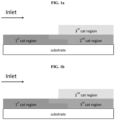
- FIG. 1a depicts a first configuration in which first catalytic region extends from the inlet end, second catalytic region extends from the outlet end and partially covers the first catalytic region, and third catalytic region extends from the outlet end and partially covers the first catalytic region.
- the first, catalytic region can extend for 5 to 50 percent or 10 to 50 percent of the axial length L; more preferably, 20 to 50 percent of the axial length L; and even more preferably, 25 to 40 percent of the axial length L.
- the second, and third catalytic region each independently can extend for 30 to 95 percent or 40 to 90 percent of the axial length L; more preferably, 50 to 85 percent of the axial length L; and even more preferably, 65 to 80 percent of the axial length L.
- the overlap between the first and second catalytic regions can be at least 5%, 10%, or 15% of the axial length L.
- the overlap between the second and third catalytic regions can be at least 5%, 10%, or 15% of the axial length L.
- FIG. 1b depicts a variation of the first configuration, with 2 nd catalytic region overlies 3 rd catalytic region.
- FIG. 2a depicts a second configuration in which second catalytic region extends from the outlet end, first catalytic region extends from the inlet end, and third catalytic region extends from the outlet end and covers the first catalytic region.
- FIG. 2b depicts a variation of the second configuration, with 2 nd catalytic region overlies 3 rd catalytic region.
- FIG. 3a depicts a third configuration in which second catalytic region extends from the outlet end; third catalytic region extends from the outlet end; and first catalytic region extends from the inlet end, partially covers the third catalytic region.
- FIG. 3b depicts a variation of the third configuration, with 2 nd catalytic region overlies 3 rd catalytic region.
- FIG. 4a depicts a fourth configuration in which second catalytic region extends from the outlet end, third catalytic region extends from the outlet end and partially covers the second catalytic region, and first catalytic region extends from the inlet end, partially covers the third catalytic region.
- FIG. 4b depicts a variation of the fourth configuration, with 2 nd catalytic region overlies 3 rd catalytic region.
- FIG. 5a depicts a fifth configuration in which second catalytic region extends from the outlet end, third catalytic region extends from the outlet end and covers the second catalytic region, and first catalytic region extends from the inlet end, partially covers the third catalytic region.
- FIG. 5b depicts a variation of the fifth configuration, with 2 nd catalytic region overlies 3 rd catalytic region.
- FIG. 6a depicts a sixth configuration in which second catalytic region extends from the outlet end, third catalytic region extends from the outlet end and partially covers the second catalytic region, and first catalytic region extends from the inlet end.
- FIG. 6b depicts a variation of the sixth configuration, with 2 nd catalytic region overlies 3 rd catalytic region.
- FIG. 7a depicts a seventh configuration in which second catalytic region extends from the outlet end, third catalytic region extends from the outlet end and covers the second catalytic region, and first catalytic region extends from the inlet end.
- the substrate is a flow-through monolith.
- FIG. 7b depicts a variation of the seventh configuration, with 2 nd catalytic region overlies 3 rd catalytic region.
- the flow-through monolith substrate has a first face and a second face defining a longitudinal direction there between.
- the flow-through monolith substrate has a plurality of channels extending between the first face and the second face.
- the plurality of channels extends in the longitudinal direction and provide a plurality of inner surfaces (e.g. the surfaces of the walls defining each channel).
- Each of the plurality of channels has an opening at the first face and an opening at the second face.
- the flow-through monolith substrate is not a wall flow filter.
- the first face is typically at an inlet end of the substrate and the second face is at an outlet end of the substrate.
- the channels may be of a constant width and each plurality of channels may have a uniform channel width.
- the monolith substrate has from 300 to 900 channels per square inch, preferably from 400 to 800.
- the density of open first channels and closed second channels is from 600 to 700 channels per square inch.
- the channels can have cross sections that are rectangular, square, circular, oval, triangular, hexagonal, or other polygonal shapes.
- the monolith substrate acts as a support for holding catalytic material.
- Suitable materials for forming the monolith substrate include ceramic-like materials such as cordierite, silicon carbide, silicon nitride, zirconia, mullite, spodumene, alumina-silica magnesia or zirconium silicate, or of porous, refractory metal. Such materials and their use in the manufacture of porous monolith substrates are well known in the art.
- the flow-through monolith substrate described herein is a single component (i.e. a single brick). Nonetheless, when forming an emission treatment system, the substrate used may be formed by adhering together a plurality of channels or by adhering together a plurality of smaller substrates as described herein. Such techniques are well known in the art, as well as suitable casings and configurations of the emission treatment system.
- the ceramic substrate may be made of any suitable refractory material, e.g., alumina, silica, ceria, zirconia, magnesia, zeolites, silicon nitride, silicon carbide, zirconium silicates, magnesium silicates, aluminosilicates and metallo aluminosilicates (such as cordierite and spodumene), or a mixture or mixed oxide of any two or more thereof. Cordierite, a magnesium aluminosilicate, and silicon carbide are particularly preferred.
- the metallic substrate may be made of any suitable metal, and in particular heat-resistant metals and metal alloys such as titanium and stainless steel as well as ferritic alloys containing iron, nickel, chromium, and/or aluminium in addition to other trace metals.
- the first catalytic region can be supported/deposited directly on the substrate ( e.g. , see FIGs. 1a-7b ).
- the second catalytic region can be supported/deposited directly on the substrate ( e.g ., see FIGs. 1a , 2a , 3a , 4a , 5a , 6a , and 7a ).
- the third catalytic region is supported/deposited directly on the substrate ( e.g ., see FIGs. 1b , 2b , 3b , 4b , 5b , 6b , and 7b ).
- At least 50% of the first catalytic region is not covered by the second catalytic region and/or the third catalytic region.
- at least 60%, 70%, or 80% of the first catalytic region is not covered by the second catalytic region and/or the third catalytic region.
- at least 90% or 95% of the first catalytic region is not covered by the second catalytic region and/or the third catalytic region.
- 100% of the first catalytic region is not covered by the second catalytic region and/or the third catalytic region.
- Another aspect of the present disclosure is directed to a method for treating a vehicular exhaust gas containing NO x , CO, and HC using the catalyst article described herein.
- Catalytic converters equipped with the TWC made according to this method show improved compared to conventional TWC (with the same PGM loading), also show especially improved performance in cold start stage and better THC and NO x light off performance.
- Another aspect of the present disclosure is directed to a system for treating vehicular exhaust gas comprising the catalyst article described herein in conjunction with a conduit for transferring the exhaust gas through the system.
- region refers to an area on a substrate, typically obtained by drying and/or calcining a washcoat.
- a “region” can, for example, be disposed or supported on a substrate as a “layer” or a “zone”.
- the area or arrangement on a substrate is generally controlled during the process of applying the washcoat to the substrate.
- the "region” typically has distinct boundaries or edges (i.e. it is possible to distinguish one region from another region using conventional analytical techniques).
- the "region" has a substantially uniform length.
- the reference to a "substantially uniform length” in this context refers to a length that does not deviate (e.g. the difference between the maximum and minimum length) by more than 10%, preferably does not deviate by more than 5 %, more preferably does not deviate by more than 1 %, from its mean value.
- each "region" has a substantially uniform composition (i.e. there is no substantial difference in the composition of the washcoat when comparing one part of the region with another part of that region).
- substantially uniform composition in this context refers to a material (e.g. region) where the difference in composition when comparing one part of the region with another part of the region is 5% or less, usually 2.5% or less, and most commonly 1% or less.
- zone refers to a region having a length that is less than the total length of the substrate, such as ⁇ 75 % of the total length of the substrate.
- a “zone” typically has a length (i.e. a substantially uniform length) of at least 5% (e.g. ⁇ 5 %) of the total length of the substrate.
- the total length of a substrate is the distance between its inlet end and its outlet end (e.g. the opposing ends of the substrate).
- any reference to a "zone disposed at an inlet end of the substrate” used herein refers to a zone disposed or supported on a substrate where the zone is nearer to an inlet end of the substrate than the zone is to an outlet end of the substrate.
- the midpoint of the zone i.e. at half its length
- the midpoint of the zone is nearer to the inlet end of the substrate than the midpoint is to the outlet end of the substrate.
- any reference to a "zone disposed at an outlet end of the substrate” used herein refers to a zone disposed or supported on a substrate where the zone is nearer to an outlet end of the substrate than the zone is to an inlet end of the substrate.
- the midpoint of the zone i.e. at half its length
- is nearer to the outlet end of the substrate than the midpoint is to the inlet end of the substrate.
- any reference to a "zone disposed at an inlet end of the substrate” refers to a zone disposed or supported on the substrate that is:
- any reference to a "zone disposed at an outlet end of the substrate" when the substrate is a wall-flow filter refers to a zone disposed or supported on the substrate that is:
- a zone may satisfy both (a) and (b) when the washcoat is present in the wall of the wall-flow filter (i.e. the zone is in-wall).
- washcoat is well known in the art and refers to an adherent coating that is applied to a substrate usually during production of a catalyst.
- platinum group metal generally refers to a metal selected from the group consisting of Ru, Rh, Pd, Os, Ir and Pt, preferably a metal selected from the group consisting of Ru, Rh, Pd, Ir and Pt. In general, the term “PGM” preferably refers to a metal selected from the group consisting of Rh, Pt and Pd.
- mixture oxide generally refers to a mixture of oxides in a single phase, as is conventionally known in the art.
- composite oxide as used herein generally refers to a composition of oxides having more than one phase, as is conventionally known in the art.
- substantially free of as used herein with reference to a material, typically in the context of the content of a region, a layer or a zone, means that the material in a minor amount, such as ⁇ 5 % by weight, preferably ⁇ 2 % by weight, more preferably ⁇ 1 % by weight.
- the expression “substantially free of” embraces the expression “does not comprise.”
- the expression "essentially free of” as used herein with reference to a material means that the material in a trace amount, such as ⁇ 1 % by weight, preferably ⁇ 0.5 % by weight, more preferably ⁇ 0.1 % by weight.
- the expression “essentially free of” embraces the expression “does not comprise.”
- any reference to an amount of dopant, particularly a total amount, expressed as a % by weight as used herein refers to the weight of the support material or the refractory metal oxide thereof.
- loading refers to a measurement in units of g/ft 3 on a metal weight basis.
- Comparative Catalyst A is a commercial three-way (Pd-Rh) catalyst with a double-layered zone structure.
- the bottom layer consists of Pd supported on a washcoat of a first CeZr mixed oxide, La-stabilized alumina, and Ba promotor.
- the washcoat loading of the bottom layer was about 1.9 g/in 3 with a Pd loading of 81 g/ft 3 and 34 g/ft 3 [front (50%) and rear (50%), respectively].
- This washcoat was coated from the inlet and outlet face of a ceramic substrate (600 cpsi, 2.5 mil wall thickness) using standard coating procedures with coating depth targeted of 50% of the substrate length, dried at 90 °C and calcined at 500 °C for 45 mins.
- the top layer consists of Rh supported on a washcoat of a second CeZr mixed oxide, La-stabilized alumina, and Ba promotor.
- the washcoat loading of the top layer was about 1.6 g/in 3 with a Rh loading of 4.5 g/ft 3 .
- This washcoat was coated from the inlet and outlet face of a ceramic substrate (600 cpsi, 2.5 mil wall thickness) using standard coating procedures with coating depth targeted of 50% of the substrate length, dried at 90 °C and calcined at 500 °C for 45 mins.
- the total washcoat loading of Comparative Catalyst A was about 3.5 g/in 3 .
- Ceria amount in the bottom layer was about 23.5 g, with a ceria loading of 0.36 g/in 3 .
- Ceria amount in the top layer was about 15.5 g, with a ceria loading of 0.24 g/in 3 .
- the first catalytic region consists of Rh supported on a washcoat of a first CeZr mixed oxide, Pd, La-stabilized alumina, and Ba promotor.
- the washcoat loading of the first catalytic region was about 1.5 g/in 3 with a 133 g/ft 3 of Pd and of 3.6 g/ft 3 of Rh loading.
- This washcoat was coated from the inlet face of the ceramic substrate containing the first catalytic region from above, using standard coating procedures with coating depth targeted of 35% of the substrate length, dried at 90 °C.
- the second catalytic region consists of Pd supported on a washcoat of a first CeZr mixed oxide, La-stabilized alumina, and Ba promotor.
- the washcoat loading of the second catalytic region was about 1.8 g/in 3 with a Pd loading of 18 g/ft 3 .
- This washcoat was coated from the outlet face of a ceramic substrate (600 cpsi, 2.5 mil wall thickness) using standard coating procedures with coating depth targeted of 65% of the substrate length, dried at 90 °C and calcined at 500 °C for 45 mins.
- the third catalytic region consists of Rh supported on a washcoat of a third CeZr mixed oxide and La-stabilized alumina.
- the washcoat loading of the third catalytic region was about 1.7 g/in 3 with a Rh loading of 4.5 g/ft 3 .
- the third washcoat was then coated from the outlet face of the ceramic substrate containing the first and the second catalytic regions from above, using standard coating procedures with coating depth targeted of 90% of the substrate length, dried at 90 °C and calcined at 500 °C for 45 mins.
- the coating order was second, first and third region. ( E.g., see FIG. 2a )
- Catalyst C was prepared according to the similar procedure as Catalyst B with the exception that the coating order was changed to second, third and first region. ( E.g., see FIG. 3a )
- Catalyst D was prepared according to the similar procedure as Catalyst C with the exception that first and second catalytic region lengths were changed from 35% and 65 % to 30% and 70 %, respectively.
- Catalyst E was prepared according to the similar procedure as Catalyst C with the exception that Pd/Rh loading in first catalytic region was 133/4.1 g/ft 3 .
- Catalyst F was prepared according to the similar procedure as Catalyst C with the exception that Pd/Rh loading in first catalytic region was 133/8.5 g/ft 3 .
- Table A summarizes ceria amount and ceria loading in each catalytic region of Catalysts B-F.
- Table A Ceria amount/loading in Catalyst B-F 1 st Catalytic Region 2 nd Catalytic Region 3 rd Catalytic Region CeO 2 amount (g) CeO 2 loading (g/in 3 ) CeO 2 amount (g) CeO 2 loading (g/in 3 ) CeO 2 amount (g) CeO 2 loading (g/in 3 ) Catalyst B 4.0 0.17 15.4 0.36 6.8 0.16 Catalyst C 4.0 0.17 15.4 0.36 6.8 0.16 Catalyst D 3.5 0.17 16.5 0.36 7.3 0.16 Catalyst E 4.0 0.17 15.4 0.36 6.8 0.16 Catalyst F 4.0 0.17 15.4 0.36 6.8 0.16
- Comparative Catalyst A and Catalysts B-D were tested separately over a vehicle of 1.0-liter engine with WLTC.
- Comparative Catalyst A and Catalysts B-D were bench aged under 4.3-L engine in the same run for 50 hrs with four mode aging cycle, with peak bed temperature at 980 °C of the catalysts.
- Bag data from the tailpipe are shown in Table 3 .
- Catalysts B, C and D of the present invention presents significantly lower emission of THC, CO, and NO x compared with Comparative Catalyst A.
- Table 3 Results of Exhaust Emissions by Vehicle Diluted Bag Data Exhaust Emissions (g/km) THC NMHC CO NO x Comparative Catalyst A 0.0398 0.0345 0.8176 0.0185
- Catalyst B 0.0258 0.0225 0.4531 0.0152
- Catalyst C 0.0250 0.0212 0.4108 0.0124 Catalyst D 0.0221 0.0201 0.4595 0.0121
- Catalyst C, Catalyst E, and Catalyst F of the present invention present lower emission of THC, CO, and NO x , compared with Comparative Catalyst A (e.g ., see the improved performance related with around 45 %, 47%, and 50 % improvement respectively on THC, CO, and NO x emission, when Catalyst F is compared with Comparative Catalyst A).
Landscapes
- Chemical & Material Sciences (AREA)
- Engineering & Computer Science (AREA)
- Chemical Kinetics & Catalysis (AREA)
- Materials Engineering (AREA)
- Organic Chemistry (AREA)
- Combustion & Propulsion (AREA)
- General Engineering & Computer Science (AREA)
- Mechanical Engineering (AREA)
- Health & Medical Sciences (AREA)
- Toxicology (AREA)
- Biomedical Technology (AREA)
- Environmental & Geological Engineering (AREA)
- Analytical Chemistry (AREA)
- General Chemical & Material Sciences (AREA)
- Oil, Petroleum & Natural Gas (AREA)
- Catalysts (AREA)
- Exhaust Gas After Treatment (AREA)
- Exhaust Gas Treatment By Means Of Catalyst (AREA)
Description
- The present invention relates to a catalyzed article useful in treating exhaust gas emissions from gasoline engines.
- Internal combustion engines produce exhaust gases containing a variety of pollutants, including hydrocarbons (HCs), carbon monoxide (CO), and nitrogen oxides ("NOx"). Emission control systems, including exhaust gas catalytic conversion catalysts, are widely utilized to reduce the amount of these pollutants emitted to atmosphere. A commonly used catalyst for gasoline engine exhaust treatments is the TWC (three way catalyst). TWCs perform three main functions: (1) oxidation of CO; (2) oxidation of unburnt HCs; and (3) reduction of NOx.
- In most catalytic converters, the TWC is coated onto a high surface area substrate that can withstand high temperatures, such as flow-through honeycomb substrates. The large surface area of these substrates facilitates the improvement of the efficiency of the heterogeneous reactions, but can also contribute to the increase of exhaust backpressure, i.e., restrictions on the flow of exhaust gas from the engine to the tail pipe. Despite advances in TWC technology, there remains a need for improved catalytic converters for certain engine platforms that simultaneously improve the performance in cold start stage and/or give better light off performance. This invention solves these problems amongst others.
-
EP 3072588 provides a catalyst for purification of exhaust gas, which comprises a noble metal supported on a catalyst support comprising a predetermined amount of ceria supported on a surface of a composite oxide composed of alumina, zirconia, and titania, exhibiting a high heat resistance and a high catalytic activity.EP 3072588 extends to a NOx storage-reduction catalyst comprising the catalyst for purification of exhaust gas and a NOx storage material. -
WO 2017/117071 relates to coated substrates useful in catalytic converters. The coated substrates can have two washcoat layers, and in some embodiments, the first washcoat layer is divided into two zones. The substrates can be used in catalytic converters and emission control systems for treatment of exhaust gases from gasoline engines. -
US 2018/978898 discloses an oxidation catalyst for treating hydrocarbons in an exhaust gas produced by an internal combustion engine, wherein the oxidation catalyst comprises a region disposed on a substrate, wherein the region comprises ruthenium supported on a support material comprising a refractory oxide. -
US 2012/0128557 A1 relates to a layered, three-way conversion catalyst having the capability of simultaneously catalyzing the oxidation of hydrocarbons and carbon monoxide and the reduction of nitrogen oxides being separated in a front and rear portion. Further provided is a catalytic composite material of a single front and two rear layers in conjunction with a substrate, where each of the layers includes a support, all layers comprise a platinum group metal component, and the rear bottom layer is substantially free of an oxygen storage component. - One aspect of the present disclosure is directed to a catalyst for treating gasoline engine exhaust gas comprising: a first catalytic region beginning at the inlet end and extending for less than the axial length L, wherein the first catalytic region comprises a first palladium component and a first oxygen storage capacity (OSC) material comprising ceria; a second catalytic region beginning at the outlet end and extending for less than the axial length L, wherein the second catalytic region comprises a second palladium component and a second OSC material comprising ceria; a third catalytic region beginning at the outlet end and extending for less than the axial length L, wherein the third catalytic region comprises a third rhodium component and a third OSC material comprising ceria; wherein at least a portion of the first catalytic region is not covered by the second catalytic region and/or the third catalytic region; and wherein (a) the ceria amount in the first catalytic region is less than 50% of the total ceria amount in the first, second, and third catalytic regions; or (b) the ceria loading in the first catalytic region is less than 50% of the sum of the ceria loading in the first, second, and third catalytic regions.
- The invention also encompasses an exhaust system for internal combustion engines that comprises the three-way catalyst component of the invention.
- The invention also encompasses treating an exhaust gas from an internal combustion engine, in particular for treating exhaust gas from a gasoline engine. The method comprises contacting the exhaust gas with the three-way catalyst component of the invention.
-
-
FIG. 1a depicts a first configuration in which first catalytic region extends from the inlet end, second catalytic region extends from the outlet end and partially covers the first catalytic region, and third catalytic region extends from the outlet end and partially covers the first catalytic region. -
FIG. 1b depicts a variation ofFIG. 1a . -
FIG. 2a depicts a second configuration in which second catalytic region extends from the outlet end, first catalytic region extends from the inlet end, and third catalytic region extends from the outlet end and covers the first catalytic region. -
FIG. 2b depicts a variation ofFIG. 2a . -
FIG. 3a depicts a third configuration in which second catalytic region extends from the outlet end; third catalytic region extends from the outlet end; and first catalytic region extends from the inlet end, partially covers the third catalytic region. -
FIG. 3b depicts a variation ofFIG. 3a . -
FIG. 4a depicts a fourth configuration in which second catalytic region extends from the outlet end, third catalytic region extends from the outlet end and partially covers the second catalytic region, and first catalytic region extends from the inlet end, partially covers the third catalytic region. -
FIG. 4b depicts a variation ofFIG. 4a . -
FIG. 5a depicts a fifth configuration in which second catalytic region extends from the outlet end, third catalytic region extends from the outlet end and covers the second catalytic region, and first catalytic region extends from the inlet end, partially covers the third catalytic region. -
FIG. 5b depicts a variation ofFIG. 5a . -
FIG. 6a depicts a sixth configuration in which second catalytic region extends from the outlet end, third catalytic region extends from the outlet end and partially covers the second catalytic region, and first catalytic region extends from the inlet end. -
FIG. 6b depicts a variation ofFIG. 6a . -
FIG. 7a depicts a seventh configuration in which second catalytic region extends from the outlet end, third catalytic region extends from the outlet end and covers the second catalytic region, and first catalytic region extends from the inlet end. Preferably the substrate is a flow-through monolith. -
FIG. 7b depicts a variation ofFIG. 7a . - The present invention is directed to the catalytic treatment of combustion exhaust gas, such as that produced by gasoline and other engines, and to related catalysts and systems. More specifically, the invention relates the simultaneous treatment of NOx, CO, and HC in a vehicular exhaust system. The inventors have discovered a synergistic relationship between the certain catalytically active metals and their ways of coating that unexpectedly produces a high conversion rate for NOx, CO, and HC; improves the performance in cold start stage; and gives better light off performance; and gives low back pressure. The processes of the present invention also reduce costs of the catalyst.
- One aspect of the present disclosure is directed to a catalyst for treating gasoline engine exhaust gas comprising: a first catalytic region beginning at the inlet end and extending for less than the axial length L, wherein the first catalytic region comprises a first palladium component and a first oxygen storage capacity (OSC) material comprising ceria; a second catalytic region beginning at the outlet end and extending for less than the axial length L, wherein the second catalytic region comprises a second palladium component and a second OSC material comprising ceria; a third catalytic region beginning at the outlet end and extending for less than the axial length L, wherein the third catalytic region comprises a third rhodium component and a third OSC material comprising ceria; wherein at least a portion of the first catalytic region is not covered by the second catalytic region and/or the third catalytic region; and wherein (a) the ceria amount in the first catalytic region is less than 50% of the total ceria amount in the first, second, and third catalytic regions; or (b) the ceria loading in the first catalytic region is less than 50% of the sum of the ceria loading in the first, second, and third catalytic regions.
- The inventors have found that these catalysts in this way of coating show better catalyst performance that is not achieved using the catalyst separately or in conventional ways of coating. Among the unexpected benefits of the present invention are improved light off performance, during vehicle cold start stage, significantly reduced emissions of exhaust pollutions, and thus more easily achieved emission targets, compared to conventional TWC catalysts of similar concentration (e.g., washcoat loadings). The achievement of these benefits leads to the amounts of noble metals used in the catalysts and lower costs.
- The first catalytic region can extend for 1 to 50 percent of the axial length L. Preferably, the first catalytic region can extend for 10 to 40 percent, more preferably, 25 to 35 percent of the axial length L.
- The first catalyst layer can comprise PGM metals other than the first palladium component, such as platinum and/or rhodium. The first catalytic region can further comprise a first rhodium component.
- The first catalytic region can comprise 0.1-300 g/ft3 of the first palladium or rhodium palladium component. Preferably, the first catalytic region can comprise 50-250 g/ft3 of the first palladium or rhodium palladium component, more preferably, 100-220 g/ft3 of the first palladium or rhodium palladium component, wherein the weight ratio of rhodium to palladium can be 60:1 to 1:60, preferably 30:1 to 1:30, more preferably 10:1 to 1:10.
- The total washcoat loading of the first catalyst region can be less than 3.5 g/in3, preferably, less than 3.0 g/in3, 2.5 g/in3, or 1.5 g/in3.
- The ceria amount in the first catalytic region can be no greater than 40%, 30%, 20%, or even 15% of the total ceria amount in the first, second, and third catalytic regions; alternatively or in addition, the ceria loading in the first catalytic region can be no greater than 40%, 30%, or even 25% of the sum of the ceria loading in the first, second, and third catalytic regions.
- The first OSC material is preferably selected from the group consisting of cerium oxide, a ceria-zirconia mixed oxide, and an alumina-ceria-zirconia mixed oxide. More preferably, the first OSC material comprises the ceria-zirconia mixed oxide. The ceria-zirconia mixed oxide can further comprise some dopants, such as lanthanum, neodymium, praseodymium, yttrium oxides, etc. In addition, the first OSC material may function as a support material for the first palladium component.
- The first catalytic region can further comprise a first alkali or alkaline earth metal component and/or a first inorganic oxide.
- The first palladium component can be supported on both the first inorganic oxide and the first OSC material.
- The ceria-zirconia mixed oxide can have a molar ratio of zirconia to ceria at least 50:50, preferably, higher than 60:40, more preferably, higher than 75:25.
- The first OSC material (e.g., ceria-zirconia mixed oxide) can be from 10 to 90 wt%, preferably, 25-75 wt%, more preferably, 30-60 wt%, based on the total washcoat loading of the first catalytic region.
- The first OSC material loading in the first catalytic region can be less than 1.5 g/in3. In some embodiments, the first OSC material loading in the first catalytic region is no greater than 1.2 g/in3, 1.0 g/in3, 0.9 g/in3, 0.8 g/in3, or 0.7 g/in3.
- In some embodiments, the first alkali or alkaline earth metal may be deposited on the first OSC material. Alternatively, or in addition, the first alkali or alkaline earth metal may be deposited on the first inorganic oxide. That is, in some embodiments, the first alkali or alkaline earth metal may be deposited on, i.e. present on, both the first OSC material and the first inorganic oxide.
- The first alkali or alkaline earth metal is generally in contact with the first inorganic oxide. Preferably the first alkali or alkaline earth metal is supported on the first inorganic oxide. Alternatively, the first alkali or alkaline earth metal may be in contact with the first OSC material.
- The first alkali or alkaline earth metal is preferably barium, or strontium, and mixed oxides or composite oxides thereof. Preferably the barium or strontium, where present, is loaded in an amount of 0.1 to 15 wt%, and more preferably 3 to 10 wt% of barium or strontium, based on the total weight of the first catalytic region.
- It is even more preferable that the first alkali or alkaline earth metal is strontium. The strontium, where present, is preferably loaded in an amount of 0.1 to 15 wt%, and more preferably 3 to 10 wt%, based on the total weight of the first catalytic region.
- It is also preferable that the first alkali or alkaline earth metal is mixed oxides or composite oxide of barium and strontium. Preferably, the mixed oxides or composite oxide of barium and strontium is present in an amount of 0.1 to 15 wt%, and more preferably 3 to 10 wt%, based on the total weight of the first catalytic region. It is more preferable that the first alkali or alkaline earth metal is composite oxide of barium and strontium.
- Preferably the barium or the strontium is present as BaCOs or SrCO3. Such a material can be performed by any method known in the art, for example incipient wetness impregnation or spray-drying.
- The first inorganic oxide is preferably an oxide of
Groups - The first OSC material and the first inorganic oxide can have a weight ratio of no greater than 10:1, preferably, no greater than 8:1 or 5:1, more preferably, no greater than 4:1 or 3:1, most preferably, no greater than 2: 1.
- Alternatively, the first OSC material and the first inorganic oxide can have a weight ratio of 10:1 to 1:10, preferably, 8:1 to 1:8 or 5:1 to 1:5; more preferably, 4:1 to 1:4 or 3:1 to 1:3; and most preferably, 2:1 to 1:2.
- The second catalytic region can be essentially free of PGM metals other than the second palladium component.
- The second catalytic region can extend for 50 to 90 percent of the axial length L. Preferably, the second catalytic region can extend for 55 to 85 percent, more preferably, 60 to 80 percent of the axial length L.
- The second catalytic region can comprise PGM metals other than the second palladium component, such as platinum and/or rhodium. The second catalytic region can comprise 0.1-100 g/ft3 of the second palladium or platinum palladium component. Preferably, the second catalytic region can comprise 5-60 g/ft3, more preferably, 10-50 g/ft3 of the second palladium or platinum palladium component, wherein the weight ratio of platinum to palladium can be 60:1 to 1:60, preferably 30:1 to 1:30, more preferably 10:1 to 1:10.
- The second OSC material is preferably selected from the group consisting of cerium oxide, a ceria-zirconia mixed oxide, and an alumina-ceria-zirconia mixed oxide. More preferably, the second OSC material comprises the ceria-zirconia mixed oxide. In addition, the second OSC material may further comprise one or more of dopants like lanthanum, neodymium, praseodymium, yttrium etc. Moreover, the second OSC material may have the function as a support material for the second palladium component.
- The second catalytic region can further comprise a second alkali or alkaline earth metal component and/or a second inorganic oxide.
- The second palladium or platinum palladium component can be supported on both the second inorganic oxide and the second OSC material.
- The ceria-zirconia mixed oxide can have a molar ratio of zirconia to ceria at least 50:50, preferably, higher than 60:40, more preferably, higher than 75:25.
- The second OSC material (e.g., ceria-zirconia mixed oxide) can be from 10 to 90 wt%, preferably, 25-75 wt%, more preferably, 30-60 wt%, based on the total washcoat loading of the second catalytic region.
- The second OSC material loading in the second catalytic region can be less than 1.5 g/in3. In some embodiments, the second OSC material loading in the second catalytic region is no greater than 1.2 g/in3, 1.0 g/in3, 0.9 g/in3, 0.8 g/in3, or 0.7 g/in3.
- The total washcoat loading of the second catalyst region can be less than 3.5 g/in3, preferably, less than 3.0 g/in3, 2.5 g/in3, or 1.5 g/in3.
- In some embodiments, the second alkali or alkaline earth metal may be deposited on the second OSC material. Alternatively, or in addition, the second alkali or alkaline earth metal may be deposited on the second inorganic oxide. That is, in some embodiments, the second alkali or alkaline earth metal may be deposited on, i.e. present on, both the second OSC material and the second inorganic oxide.
- The second alkali or alkaline earth metal is generally in contact with the second inorganic oxide. Preferably the second alkali or alkaline earth metal is supported on the second inorganic oxide. In addition to, or alternatively to, being in contact with the second inorganic oxide, the second alkali or alkaline earth metal may be in contact with the second OSC material.
- The second alkali or alkaline earth metal is preferably barium, strontium, mixed oxides or composite oxides thereof. Preferably the barium or strontium, where present, is in an amount of 0.1 to 15 wt%, and more preferably 3 to 10 wt% of barium or strontium, based on the total weight of the second catalytic region.
- It is even more preferable that the second alkali or alkaline earth metal is strontium. The strontium, where present, is preferably present in an amount of 0.1 to 15 wt%, and more preferably 3 to 10 wt%, based on the total weight of the second catalytic region.
- It is also preferable that the second alkali or alkaline earth metal is mixed oxides or composite oxide of barium and strontium. Preferably, the mixed oxides or composite oxide of barium and strontium is present in an amount of 0.1 to 15 wt%, and more preferably 3 to 10 wt%, based on the total weight of the second catalytic region. It is more preferable that the second alkali or alkaline earth metal is composite oxide of barium and strontium.
- Preferably the barium or strontium is present as BaCOs or SrCO3. Such a material can be performed by any method known in the art, for example incipient wetness impregnation or spray-drying.
- The second inorganic oxide is preferably an oxide of
Groups - The second OSC material and the second inorganic oxide can have a weight ratio of no greater than 10:1, preferably, no greater than 8:1 or 5:1, more preferably, no greater than 4:1 or 3:1, most preferably, no greater than 2:1.
- Alternatively, the second OSC material and the second inorganic oxide can have a weight ratio of 10:1 to 1:10, preferably, 8:1 to 1:8 or 5:1 to 1:5; more preferably, 4:1 to 1:4 or 3:1 to 1:3; and most preferably, 2:1 to 1:2.
- The third catalytic region can extend for 50 to 99 percent of the axial length L. Preferably, the third catalytic region can extend for 50 to 95 percent, more preferably, 60 to 95 percent of the axial length L.
- The third catalytic region can be essentially free of PGM metals other than the third rhodium component.
- The third catalytic region can comprise 0.1-20 g/ft3 of the third rhodium or platinum rhodium component. In some embodiments, the third catalytic region can comprise 3-15 g/ft3 or 5-13 g/ft3 of the third rhodium or platinum rhodium component, wherein the weight ratio of platinum to rhodium can be 20:1 to 1:20, 15:1 to 1:15, or 10:1 to 1:10.
- The total washcoat loading of the second catalyst region can be less than 3.5 g/in3; preferably, less than 3.0 g/in3 or 2 g/in3; more preferably, less than 1.5 g/in3 or 1.0 g/in3.
- The third OSC material is preferably selected from the group consisting of cerium oxide, a ceria-zirconia mixed oxide, and an alumina-ceria-zirconia mixed oxide. Preferably the third OSC material comprises ceria-zirconium mixed oxide, with one or more of dopants of lanthanum, neodymium, yttrium, praseodymium, etc. In addition, the third OSC material may function as a support material for the third rhodium component.
- The third catalytic region can further comprise a third alkali or alkaline earth metal component and/or a third inorganic oxide.
- The ceria-zirconia mixed oxide can have a molar ratio of zirconia to ceria at least 50:50; preferably, higher than 60:40; and more preferably, higher than 80:20.
- The third OSC material can be from 10 to 90 wt%; preferably, 25-75 wt%; more preferably, 35-65 wt %; based on the total washcoat loading of the third catalytic region.
- The third OSC material loading in the third catalytic region can be less than 2 g/in3. In some embodiments, the third OSC material loading in the third catalytic region is no greater than 1.5 g/in3, 1.2 g/in3, 1.0 g/in3, or 0.5 g/in3.
- In some embodiments, the ceria loading in the second catalytic region is greater than the ceria loading in the third catalytic region. In further embodiments, the ratio of the ceria loading in the second catalytic region to the ceria loading in the third catalytic region can be at least 3:2 or 2:1.
- The third catalytic region can be substantially free of the third alkali or alkaline earth metal. Reference to "substantially free" means that the recited material may be intentionally or unintentionally present in the recited layer in minor amounts. For example, the alkali or alkaline earth metal might be present in the first and/or the second catalytic regions and some of the alkali or alkaline earth metal might migrate/leach into the third catalytic region unintentionally during the coating processes.
- The third inorganic oxide is preferably an oxide of
Groups - Preferred the third inorganic oxides preferably have a fresh surface area of greater than 80 m2/g, pore volumes in the range 0.1 to 4 mL/g. High surface area inorganic oxides having a surface area greater than 100 m2/g are particularly preferred, e.g. high surface area alumina. Other preferred the third inorganic oxides include lanthanum/alumina composite oxides, optionally further comprising a zirconium-containing component, e.g. zirconia. In such cases the zirconium may be present on the surface of the lanthanum/alumina composite oxide, e.g. as a coating.
- The third OSC material and the third inorganic oxide can have a weight ratio of at least 1:1, preferably, at least 2:1, more preferably, at least 3:1.
- Alternatively, the third OSC material and the third inorganic oxide can have a weight ratio of 10:1 to 1:10; preferably, 8:1 to 1:8 or 5:1 to 1:5; more preferably, 4:1 to 1:4 or 3:1 to 1:3.
- In some embodiments, the first palladium component and the second palladium component has a weight ratio of from 50:1 to 1:50. In further embodiments, the first palladium component and the second palladium component has a weight ratio of from 30:1 to 1:30. In another further embodiment, the first palladium component and the second palladium component has a weight ratio of from 10:1 to 1:10. In yet another further embodiment, the first palladium component and the second palladium component has a weight ratio of from 7:1 to 1:7.
- It is preferred that the first palladium component and the second palladium component has a weight ratio of greater than 1:1, more preferred, at least 3:2, 2:1 or 3:1; even more preferred, at least 4:1, 5:1, 6:1 or 7:1.
- In some embodiments, the third rhodium component and the first palladium component has a weight ratio of from 60:1 to 1:60. Preferably, the third rhodium component and the first palladium component has a weight ratio of from 40:1 to 1:40. More preferably, the third rhodium component and the first palladium component has a weight ratio of from 30:1 to 1:30. Most preferably, the third rhodium component and the first palladium component has a weight ratio of from 10:1 to 1:10.
- In certain embodiments, the total washcoat loading in the first catalytic region can be less than 50% of the sum of the total washcoat loading in the first, second, and third catalytic regions. In further embodiments, the total washcoat loading in the first catalytic region can be no more than 40% or 30% of the sum of the total washcoat loading in the first, second, and third catalytic regions. In yet another further embodiment, the total washcoat loading in the first catalytic region can be no more than 25% of the sum of the total washcoat loading in the first, second, and third catalytic regions.
- The catalyst article of the invention may comprise further components that are known to the skilled person. For example, the compositions of the invention may further comprise at least one binder and/or at least one surfactant. Where a binder is present, dispersible alumina binders are preferred.
- The second catalytic region can overlap with the first catalytic region for 1 to 15 percent of the axial length L (e.g., see
FIG. 1a ,FIG. 2a ,FIG. 3b ,FIG. 4b , andFIG. 5b ; the first catalyst region can overlie the second catalytic region, or the second catalyst region can overlie the first catalytic region). Alternatively, the total length of the second catalytic region and the first catalytic region can equal to the axial length L. In yet another alternative, the total length of the second catalytic region and the first catalytic region can be less than the axial length L, for example, no greater than 95%, 90%, 80%, or 70% of the axial length L (e.g., seeFIGs. 6a, 6b ,7a, and 7b ). - In one aspect of the invention, various configurations of catalytic articles comprising the first, second, and third catalytic regions can be prepared as below.
-
FIG. 1a depicts a first configuration in which first catalytic region extends from the inlet end, second catalytic region extends from the outlet end and partially covers the first catalytic region, and third catalytic region extends from the outlet end and partially covers the first catalytic region. - In the first configuration, preferably, the first, catalytic region can extend for 5 to 50 percent or 10 to 50 percent of the axial length L; more preferably, 20 to 50 percent of the axial length L; and even more preferably, 25 to 40 percent of the axial length L.
- The second, and third catalytic region, each independently can extend for 30 to 95 percent or 40 to 90 percent of the axial length L; more preferably, 50 to 85 percent of the axial length L; and even more preferably, 65 to 80 percent of the axial length L. In some embodiments, the overlap between the first and second catalytic regions can be at least 5%, 10%, or 15% of the axial length L. In certain embodiments, the overlap between the second and third catalytic regions can be at least 5%, 10%, or 15% of the axial length L.
-
FIG. 1b depicts a variation of the first configuration, with 2nd catalytic region overlies 3rd catalytic region. -
FIG. 2a depicts a second configuration in which second catalytic region extends from the outlet end, first catalytic region extends from the inlet end, and third catalytic region extends from the outlet end and covers the first catalytic region. -
FIG. 2b depicts a variation of the second configuration, with 2nd catalytic region overlies 3rd catalytic region. -
FIG. 3a depicts a third configuration in which second catalytic region extends from the outlet end; third catalytic region extends from the outlet end; and first catalytic region extends from the inlet end, partially covers the third catalytic region. -
FIG. 3b depicts a variation of the third configuration, with 2nd catalytic region overlies 3rd catalytic region. -
FIG. 4a depicts a fourth configuration in which second catalytic region extends from the outlet end, third catalytic region extends from the outlet end and partially covers the second catalytic region, and first catalytic region extends from the inlet end, partially covers the third catalytic region. -
FIG. 4b depicts a variation of the fourth configuration, with 2nd catalytic region overlies 3rd catalytic region. -
FIG. 5a depicts a fifth configuration in which second catalytic region extends from the outlet end, third catalytic region extends from the outlet end and covers the second catalytic region, and first catalytic region extends from the inlet end, partially covers the third catalytic region. -
FIG. 5b depicts a variation of the fifth configuration, with 2nd catalytic region overlies 3rd catalytic region. -
FIG. 6a depicts a sixth configuration in which second catalytic region extends from the outlet end, third catalytic region extends from the outlet end and partially covers the second catalytic region, and first catalytic region extends from the inlet end. -
FIG. 6b depicts a variation of the sixth configuration, with 2nd catalytic region overlies 3rd catalytic region. -
FIG. 7a depicts a seventh configuration in which second catalytic region extends from the outlet end, third catalytic region extends from the outlet end and covers the second catalytic region, and first catalytic region extends from the inlet end. Preferably the substrate is a flow-through monolith. -
FIG. 7b depicts a variation of the seventh configuration, with 2nd catalytic region overlies 3rd catalytic region. - The flow-through monolith substrate has a first face and a second face defining a longitudinal direction there between. The flow-through monolith substrate has a plurality of channels extending between the first face and the second face. The plurality of channels extends in the longitudinal direction and provide a plurality of inner surfaces (e.g. the surfaces of the walls defining each channel). Each of the plurality of channels has an opening at the first face and an opening at the second face. For the avoidance of doubt, the flow-through monolith substrate is not a wall flow filter.
- The first face is typically at an inlet end of the substrate and the second face is at an outlet end of the substrate.
- The channels may be of a constant width and each plurality of channels may have a uniform channel width.
- Preferably within a plane orthogonal to the longitudinal direction, the monolith substrate has from 300 to 900 channels per square inch, preferably from 400 to 800. For example, on the first face, the density of open first channels and closed second channels is from 600 to 700 channels per square inch. The channels can have cross sections that are rectangular, square, circular, oval, triangular, hexagonal, or other polygonal shapes.
- The monolith substrate acts as a support for holding catalytic material. Suitable materials for forming the monolith substrate include ceramic-like materials such as cordierite, silicon carbide, silicon nitride, zirconia, mullite, spodumene, alumina-silica magnesia or zirconium silicate, or of porous, refractory metal. Such materials and their use in the manufacture of porous monolith substrates are well known in the art.
- It should be noted that the flow-through monolith substrate described herein is a single component (i.e. a single brick). Nonetheless, when forming an emission treatment system, the substrate used may be formed by adhering together a plurality of channels or by adhering together a plurality of smaller substrates as described herein. Such techniques are well known in the art, as well as suitable casings and configurations of the emission treatment system.
- In embodiments wherein the catalyst article of the present comprises a ceramic substrate, the ceramic substrate may be made of any suitable refractory material, e.g., alumina, silica, ceria, zirconia, magnesia, zeolites, silicon nitride, silicon carbide, zirconium silicates, magnesium silicates, aluminosilicates and metallo aluminosilicates (such as cordierite and spodumene), or a mixture or mixed oxide of any two or more thereof. Cordierite, a magnesium aluminosilicate, and silicon carbide are particularly preferred.
- In embodiments wherein the catalyst article of the present invention comprises a metallic substrate, the metallic substrate may be made of any suitable metal, and in particular heat-resistant metals and metal alloys such as titanium and stainless steel as well as ferritic alloys containing iron, nickel, chromium, and/or aluminium in addition to other trace metals.
- In some embodiments, the first catalytic region can be supported/deposited directly on the substrate (e.g., see
FIGs. 1a-7b ). In certain embodiments, the second catalytic region can be supported/deposited directly on the substrate (e.g., seeFIGs. 1a ,2a ,3a ,4a ,5a ,6a , and7a ). In other embodiments, the third catalytic region is supported/deposited directly on the substrate (e.g., seeFIGs. 1b ,2b ,3b ,4b ,5b ,6b , and7b ). - In certain embodiments, at least 50% of the first catalytic region is not covered by the second catalytic region and/or the third catalytic region. In preferred embodiments, at least 60%, 70%, or 80% of the first catalytic region is not covered by the second catalytic region and/or the third catalytic region. In more preferred embodiments, at least 90% or 95% of the first catalytic region is not covered by the second catalytic region and/or the third catalytic region. In most preferred embodiments, 100% of the first catalytic region is not covered by the second catalytic region and/or the third catalytic region.
- Another aspect of the present disclosure is directed to a method for treating a vehicular exhaust gas containing NOx, CO, and HC using the catalyst article described herein. Catalytic converters equipped with the TWC made according to this method show improved compared to conventional TWC (with the same PGM loading), also show especially improved performance in cold start stage and better THC and NOx light off performance.
- Another aspect of the present disclosure is directed to a system for treating vehicular exhaust gas comprising the catalyst article described herein in conjunction with a conduit for transferring the exhaust gas through the system.
- The term "region" as used herein refers to an area on a substrate, typically obtained by drying and/or calcining a washcoat. A "region" can, for example, be disposed or supported on a substrate as a "layer" or a "zone". The area or arrangement on a substrate is generally controlled during the process of applying the washcoat to the substrate. The "region" typically has distinct boundaries or edges (i.e. it is possible to distinguish one region from another region using conventional analytical techniques).
- Typically, the "region" has a substantially uniform length. The reference to a "substantially uniform length" in this context refers to a length that does not deviate (e.g. the difference between the maximum and minimum length) by more than 10%, preferably does not deviate by more than 5 %, more preferably does not deviate by more than 1 %, from its mean value.
- It is preferable that each "region" has a substantially uniform composition (i.e. there is no substantial difference in the composition of the washcoat when comparing one part of the region with another part of that region). Substantially uniform composition in this context refers to a material (e.g. region) where the difference in composition when comparing one part of the region with another part of the region is 5% or less, usually 2.5% or less, and most commonly 1% or less.
- The term "zone" as used herein refers to a region having a length that is less than the total length of the substrate, such as ≤ 75 % of the total length of the substrate. A "zone" typically has a length (i.e. a substantially uniform length) of at least 5% (e.g. ≥ 5 %) of the total length of the substrate.
- The total length of a substrate is the distance between its inlet end and its outlet end (e.g. the opposing ends of the substrate).
- Any reference to a "zone disposed at an inlet end of the substrate" used herein refers to a zone disposed or supported on a substrate where the zone is nearer to an inlet end of the substrate than the zone is to an outlet end of the substrate. Thus, the midpoint of the zone (i.e. at half its length) is nearer to the inlet end of the substrate than the midpoint is to the outlet end of the substrate. Similarly, any reference to a "zone disposed at an outlet end of the substrate" used herein refers to a zone disposed or supported on a substrate where the zone is nearer to an outlet end of the substrate than the zone is to an inlet end of the substrate. Thus, the midpoint of the zone (i.e. at half its length) is nearer to the outlet end of the substrate than the midpoint is to the inlet end of the substrate.
- When the substrate is a wall-flow filter, then generally any reference to a "zone disposed at an inlet end of the substrate" refers to a zone disposed or supported on the substrate that is:
- (a) nearer to an inlet end (e.g. open end) of an inlet channel of the substrate than the zone is to a closed end (e.g. blocked or plugged end) of the inlet channel, and/or
- (b) nearer to a closed end (e.g. blocked or plugged end) of an outlet channel of the substrate than the zone is to an outlet end (e.g. open end) of the outlet channel.
- Similarly, any reference to a "zone disposed at an outlet end of the substrate" when the substrate is a wall-flow filter refers to a zone disposed or supported on the substrate that is:
- (a) nearer to an outlet end (e.g. an open end) of an outlet channel of the substrate than the zone is to a closed end (e.g. blocked or plugged) of the outlet channel, and/or
- (b) nearer to a closed end (e.g. blocked or plugged end) of an inlet channel of the substrate than it is to an inlet end (e.g. an open end) of the inlet channel.
- A zone may satisfy both (a) and (b) when the washcoat is present in the wall of the wall-flow filter (i.e. the zone is in-wall).
- The term "washcoat" is well known in the art and refers to an adherent coating that is applied to a substrate usually during production of a catalyst.
- The acronym "PGM" as used herein refers to "platinum group metal". The term "platinum group metal" generally refers to a metal selected from the group consisting of Ru, Rh, Pd, Os, Ir and Pt, preferably a metal selected from the group consisting of Ru, Rh, Pd, Ir and Pt. In general, the term "PGM" preferably refers to a metal selected from the group consisting of Rh, Pt and Pd.
- The term "mixed oxide" as used herein generally refers to a mixture of oxides in a single phase, as is conventionally known in the art. The term "composite oxide" as used herein generally refers to a composition of oxides having more than one phase, as is conventionally known in the art.
- The expression "consist essentially" as used herein limits the scope of a feature to include the specified materials or steps, and any other materials or steps that do not materially affect the basic characteristics of that feature, such as for example minor impurities. The expression "consist essentially of" embraces the expression "consisting of".
- The expression "substantially free of" as used herein with reference to a material, typically in the context of the content of a region, a layer or a zone, means that the material in a minor amount, such as ≤ 5 % by weight, preferably ≤ 2 % by weight, more preferably ≤ 1 % by weight. The expression "substantially free of" embraces the expression "does not comprise."
- The expression "essentially free of" as used herein with reference to a material, typically in the context of the content of a region, a layer or a zone, means that the material in a trace amount, such as ≤ 1 % by weight, preferably ≤ 0.5 % by weight, more preferably ≤ 0.1 % by weight. The expression "essentially free of" embraces the expression "does not comprise."
- Any reference to an amount of dopant, particularly a total amount, expressed as a % by weight as used herein refers to the weight of the support material or the refractory metal oxide thereof.
- The term "loading" as used herein refers to a measurement in units of g/ft3 on a metal weight basis.
- The following examples merely illustrate the invention. Those skilled in the art will recognize many variations that are within the scope of the claims.
- All materials are commercially available and were obtained from known suppliers, unless noted otherwise.
- Comparative Catalyst A is a commercial three-way (Pd-Rh) catalyst with a double-layered zone structure. The bottom layer consists of Pd supported on a washcoat of a first CeZr mixed oxide, La-stabilized alumina, and Ba promotor. The washcoat loading of the bottom layer was about 1.9 g/in3 with a Pd loading of 81 g/ft3 and 34 g/ft3 [front (50%) and rear (50%), respectively]. This washcoat was coated from the inlet and outlet face of a ceramic substrate (600 cpsi, 2.5 mil wall thickness) using standard coating procedures with coating depth targeted of 50% of the substrate length, dried at 90 °C and calcined at 500 °C for 45 mins.
- The top layer consists of Rh supported on a washcoat of a second CeZr mixed oxide, La-stabilized alumina, and Ba promotor. The washcoat loading of the top layer was about 1.6 g/in3 with a Rh loading of 4.5 g/ft3. This washcoat was coated from the inlet and outlet face of a ceramic substrate (600 cpsi, 2.5 mil wall thickness) using standard coating procedures with coating depth targeted of 50% of the substrate length, dried at 90 °C and calcined at 500 °C for 45 mins.
- The total washcoat loading of Comparative Catalyst A was about 3.5 g/in3. Ceria amount in the bottom layer was about 23.5 g, with a ceria loading of 0.36 g/in3. Ceria amount in the top layer was about 15.5 g, with a ceria loading of 0.24 g/in3.
- The first catalytic region consists of Rh supported on a washcoat of a first CeZr mixed oxide, Pd, La-stabilized alumina, and Ba promotor. The washcoat loading of the first catalytic region was about 1.5 g/in3 with a 133 g/ft3 of Pd and of 3.6 g/ft3 of Rh loading.
- This washcoat was coated from the inlet face of the ceramic substrate containing the first catalytic region from above, using standard coating procedures with coating depth targeted of 35% of the substrate length, dried at 90 °C.
- The second catalytic region consists of Pd supported on a washcoat of a first CeZr mixed oxide, La-stabilized alumina, and Ba promotor. The washcoat loading of the second catalytic region was about 1.8 g/in3 with a Pd loading of 18 g/ft3.
- This washcoat was coated from the outlet face of a ceramic substrate (600 cpsi, 2.5 mil wall thickness) using standard coating procedures with coating depth targeted of 65% of the substrate length, dried at 90 °C and calcined at 500 °C for 45 mins.
- The third catalytic region consists of Rh supported on a washcoat of a third CeZr mixed oxide and La-stabilized alumina. The washcoat loading of the third catalytic region was about 1.7 g/in3 with a Rh loading of 4.5 g/ft3.
- The third washcoat was then coated from the outlet face of the ceramic substrate containing the first and the second catalytic regions from above, using standard coating procedures with coating depth targeted of 90% of the substrate length, dried at 90 °C and calcined at 500 °C for 45 mins.
- The coating order was second, first and third region. (E.g., see
FIG. 2a ) - Catalyst C was prepared according to the similar procedure as Catalyst B with the exception that the coating order was changed to second, third and first region. (E.g., see
FIG. 3a ) - Catalyst D was prepared according to the similar procedure as Catalyst C with the exception that first and second catalytic region lengths were changed from 35% and 65 % to 30% and 70 %, respectively.
- Catalyst E was prepared according to the similar procedure as Catalyst C with the exception that Pd/Rh loading in first catalytic region was 133/4.1 g/ft3.
- Catalyst F was prepared according to the similar procedure as Catalyst C with the exception that Pd/Rh loading in first catalytic region was 133/8.5 g/ft3.
- Table A below summarizes ceria amount and ceria loading in each catalytic region of Catalysts B-F.
Table A Ceria amount/loading in Catalyst B-F 1st Catalytic Region 2nd Catalytic Region 3rd Catalytic Region CeO2 amount (g) CeO2 loading (g/in3) CeO2 amount (g) CeO2 loading (g/in3) CeO2 amount (g) CeO2 loading (g/in3) Catalyst B 4.0 0.17 15.4 0.36 6.8 0.16 Catalyst C 4.0 0.17 15.4 0.36 6.8 0.16 Catalyst D 3.5 0.17 16.5 0.36 7.3 0.16 Catalyst E 4.0 0.17 15.4 0.36 6.8 0.16 Catalyst F 4.0 0.17 15.4 0.36 6.8 0.16 - The Back Pressure (BP) performances of Comparative Catalyst A, Catalysts B-D were tested over a gas flow mater equipment. As shown Table 1, Catalysts B-D of the present invention present significantly lower BP when compared with Comparative Catalyst A.
Table 1 Back Pressure Results Sample Back pressure [kPa] Relative BP [%] Comparative Catalyst A 9.87 100 Catalyst B 9.56 89 Catalyst C 9.55 89 Catalyst D 9.57 90 - The fresh performances of Comparative Catalyst A and Catalysts B-D were tested over a vehicle of 1.0-liter engine with WLTC (Worldwide harmonized Light vehicles Test Cycle). Bag data from the tailpipe are shown in Table 2. Catalysts B, C, and D of the present invention presents significantly lower emission of THC and NOx compared with Comparative Catalyst A. (e.g., see the improved performance related with around 22 % and 52 % improvement respectively on THC and NOx emission, when Catalyst D is compared with Comparative Catalyst A)
Table 2 Results of Exhaust Emissions by Vehicle Diluted Bag Data Exhaust Emissions (g/km) THC NMHC CO NOx Comparative Catalyst A 0.0211 0.0192 0.3402 0.0080 Catalyst B 0.0171 0.0155 0.4909 0.0036 Catalyst C 0.0169 0.0154 04997 0.0039 Catalyst D 0.0164 0.0151 0.4588 0.0038 - The bench aged samples of Comparative Catalyst A and Catalysts B-D were tested separately over a vehicle of 1.0-liter engine with WLTC. Comparative Catalyst A and Catalysts B-D were bench aged under 4.3-L engine in the same run for 50 hrs with four mode aging cycle, with peak bed temperature at 980 °C of the catalysts.
- Bag data from the tailpipe are shown in Table 3. Catalysts B, C and D of the present invention presents significantly lower emission of THC, CO, and NOx compared with Comparative Catalyst A.
Table 3 Results of Exhaust Emissions by Vehicle Diluted Bag Data Exhaust Emissions (g/km) THC NMHC CO NOx Comparative Catalyst A 0.0398 0.0345 0.8176 0.0185 Catalyst B 0.0258 0.0225 0.4531 0.0152 Catalyst C 0.0250 0.0212 0.4108 0.0124 Catalyst D 0.0221 0.0201 0.4595 0.0121 - The bench aged samples of Comparative Catalyst A, Catalyst C, E and Catalyst F were tested over a vehicle of 1.0-liter engine with WLTC. The bench aging under 4.3-L engine in the same run for 50 hrs with four mode aging cycle, with peak bed temperature at about 980 °C of the catalysts. Results of vehicle exhaust diluted bag data are shown in Table 4. Catalyst C, Catalyst E, and Catalyst F of the present invention present lower emission of THC, CO, and NOx, compared with Comparative Catalyst A (e.g., see the improved performance related with around 45 %, 47%, and 50 % improvement respectively on THC, CO, and NOx emission, when Catalyst F is compared with Comparative Catalyst A).
Table 4: Emission Results by Vehicle Diluted Bag Data Exhaust Emissions (g/km) THC NMHC CO NOx Comparative Catalyst A 0.0398 0.0345 0.8176 0.0185 Catalyst C 0.0280 0.0244 0.5302 0.0145 Catalyst E 0.0249 0.0221 0.5105 0.0127 Catalyst F 0.0218 0.0192 0.4306 0.0092
Claims (15)
- A catalyst article for treating exhaust gas comprising:a substrate comprising an inlet end, an outlet end with an axial length L;a first catalytic region beginning at the inlet end and extending for less than the axial length L, wherein the first catalytic region comprises a first palladium component and a first oxygen storage capacity material comprising ceria;wherein the catalyst article is characterized in that it further comprisesa second catalytic region beginning at the outlet end and extending for less than the axial length L, wherein the second catalytic region comprises a second palladium component and a second oxygen storage capacity material comprising ceria;a third catalytic region beginning at the outlet end and extending for less than the axial length L, wherein the third catalytic region comprises a third rhodium component and a third oxygen storage capacity material comprising ceria;wherein at least a portion of the first catalytic region is not covered by the second catalytic region and/or the third catalytic region; andwherein (a) the ceria amount in the first catalytic region is less than 50% of the total ceria amount in the first, second, and third catalytic regions; or (b) the ceria loading in the first catalytic region is less than 50% of the sum of the ceria loading in the first, second, and third catalytic regions.
- The catalyst article of claim 1, wherein the first catalytic region extends for 1 to 50 percent of the axial length L.
- The catalyst article of claim 1 or claim 2, wherein the second catalytic region extends for 50 to 90 percent of the axial length L.
- The catalyst article of any one of the preceding claims, wherein the second catalytic region overlaps with the first catalytic region for 1 to 15 percent of the axial length L.
- The catalyst article of any one of claims 1-3, wherein the total length of the second catalytic region and the first catalytic region equals to the axial length L.
- The catalyst article of any one of claims 1-3, wherein the total length of the second catalytic region and the first catalytic region is less than the axial length L.
- The catalyst article of any one of the preceding claims, wherein the third catalytic region extends for 50 to 95 percent of the axial length L.
- The catalyst article of any one of the preceding claims, wherein the first catalytic region further comprises a first rhodium component.
- The catalyst article of any one of the preceding claims wherein the first catalytic region comprises 0.1-300 g/ft3 of the first palladium component.
- The catalyst article of any one of the preceding claims, wherein the ceria amount in the first catalytic region is no greater than 40% of the total ceria amount in the first, second, and third catalytic regions.
- The catalyst article of any one of the preceding claims, wherein the ceria loading in the first catalytic region is no greater than 40% of the sum of the ceria loading in the first, second, and third catalytic regions
- The catalyst article of any one of the preceding claims, wherein the first oxygen storage capacity material is selected from the group consisting of cerium oxide, a ceria-zirconia mixed oxide, and an alumina-ceria-zirconia mixed oxide.
- The catalyst article of claim 12, wherein the first oxygen storage capacity material comprises the ceria-zirconia mixed oxide.
- The catalyst article of any one of the preceding claims, wherein the second catalytic region is essentially free of PGM metals other than the second palladium component.
- The catalyst article of any one of the preceding claims, wherein the ratio of the Pd loading in the first catalytic region and the Pd loading in the second catalytic region is at least 3:2.
Applications Claiming Priority (1)
| Application Number | Priority Date | Filing Date | Title |
|---|---|---|---|
| US202062957848P | 2020-01-07 | 2020-01-07 |
Publications (2)
| Publication Number | Publication Date |
|---|---|
| EP3848564A1 EP3848564A1 (en) | 2021-07-14 |
| EP3848564B1 true EP3848564B1 (en) | 2024-02-28 |
Family
ID=74105893
Family Applications (1)
| Application Number | Title | Priority Date | Filing Date |
|---|---|---|---|
| EP21150498.0A Active EP3848564B1 (en) | 2020-01-07 | 2021-01-07 | Catalyst |
Country Status (6)
| Country | Link |
|---|---|
| US (1) | US11642655B2 (en) |
| EP (1) | EP3848564B1 (en) |
| JP (2) | JP2023509266A (en) |
| CN (1) | CN114555224A (en) |
| BR (1) | BR112022006243A2 (en) |
| WO (1) | WO2021140326A1 (en) |
Families Citing this family (10)
| Publication number | Priority date | Publication date | Assignee | Title |
|---|---|---|---|---|
| EP3889404A1 (en) * | 2020-03-30 | 2021-10-06 | Johnson Matthey Public Limited Company | Multi-region twc catalysts for gasoline engine exhaust gas treatments with improved h2s attenuation |
| JP7355775B2 (en) * | 2021-03-05 | 2023-10-03 | トヨタ自動車株式会社 | Exhaust gas purification catalyst |
| US11986802B2 (en) * | 2021-08-31 | 2024-05-21 | Johnson Matthey Public Limited Company | Transition metal incorporated alumina for improved three way catalysts |
| WO2023061219A1 (en) * | 2021-10-12 | 2023-04-20 | Johnson Matthey (Shanghai) Chemicals Limited | Novel zoned catalysts for cng engine exhaust gas treatments with improved ammonia emission control |
| US20230364588A1 (en) * | 2022-05-13 | 2023-11-16 | Johnson Matthey Public Limited Company | Zoned twc catalysts for gasoline engine exhaust gas treatments |
| US20240001343A1 (en) * | 2022-06-30 | 2024-01-04 | Johnson Matthey (Shanghai) Chemicals Limited | Platinum enriched multi-region catalysts for cng engine exhaust gas treatments |
| DE102022130469A1 (en) | 2022-11-17 | 2024-05-23 | Umicore Ag & Co. Kg | Method and device for producing a substrate for an exhaust gas aftertreatment device |
| DE102023117464A1 (en) | 2023-07-03 | 2025-01-09 | Umicore Ag & Co. Kg | Method and device for producing a substrate for an exhaust gas aftertreatment device |
| DE102023132075A1 (en) * | 2023-11-17 | 2025-05-22 | Umicore Ag & Co. Kg | Catalytic particulate filter |
| WO2025153799A1 (en) * | 2024-01-15 | 2025-07-24 | Johnson Matthey Public Limited Company | Multi-layer twc formulations with optimalized pgm loadings |
Family Cites Families (36)
| Publication number | Priority date | Publication date | Assignee | Title |
|---|---|---|---|---|
| US5376610A (en) * | 1992-04-15 | 1994-12-27 | Nissan Motor Co., Ltd. | Catalyst for exhaust gas purification and method for exhaust gas purification |
| US5597771A (en) * | 1993-06-25 | 1997-01-28 | Engelhard Corporation | Layered catalyst composite |
| US20040001781A1 (en) * | 2002-06-27 | 2004-01-01 | Engelhard Corporation | Multi-zone catalytic converter |
| US7737077B2 (en) * | 2004-11-25 | 2010-06-15 | Cataler Corporation | Catalyst for purifying exhaust gases |
| GB0922195D0 (en) * | 2009-12-21 | 2010-02-03 | Johnson Matthey Plc | Improvements in NOx traps |
| US8557204B2 (en) * | 2010-11-22 | 2013-10-15 | Umicore Ag & Co. Kg | Three-way catalyst having an upstream single-layer catalyst |
| JP5594161B2 (en) * | 2011-01-26 | 2014-09-24 | マツダ株式会社 | Exhaust gas purification catalyst device |
| EP2802408B1 (en) * | 2011-12-22 | 2017-10-04 | Johnson Matthey Public Limited Company | Improved nox trap |
| US9034269B2 (en) * | 2012-11-29 | 2015-05-19 | Basf Se | Diesel oxidation catalyst comprising palladium, gold and ceria |
| GB2512648B (en) * | 2013-04-05 | 2018-06-20 | Johnson Matthey Plc | Filter substrate comprising three-way catalyst |
| GB2514177A (en) * | 2013-05-17 | 2014-11-19 | Johnson Matthey Plc | Oxidation catalyst for a compression ignition engine |
| JP5845234B2 (en) * | 2013-11-14 | 2016-01-20 | トヨタ自動車株式会社 | Exhaust gas purification catalyst |
| EP3151949A1 (en) * | 2014-06-06 | 2017-04-12 | Clean Diesel Technologies, Inc. | Rhodium-iron catalysts |
| JP6564637B2 (en) * | 2014-10-09 | 2019-08-21 | 株式会社キャタラー | Exhaust gas purification device |
| US20160236148A1 (en) * | 2015-02-13 | 2016-08-18 | SDCmaterials, Inc. | Zoned catalytic converters for gasoline engines with reduced rhodium content |
| US9616386B2 (en) * | 2015-03-23 | 2017-04-11 | Kabushiki Kaisha Toyota Chuo Kenkyusho | Catalyst for purification of exhaust gas, NOx storage-reduction catalyst, and method for purifying exhaust gas |
| EP3314101A4 (en) * | 2015-06-24 | 2019-02-20 | BASF Corporation | AUTOMOTIVE LAYER CATALYST COMPOSITES |
| US20170189892A1 (en) * | 2015-12-31 | 2017-07-06 | SDCmaterials, Inc. | Layered catalysts for gasoline engine exhaust |
| WO2017126631A1 (en) * | 2016-01-21 | 2017-07-27 | 株式会社キャタラー | Exhaust gas purification device |
| JP6738185B2 (en) * | 2016-04-07 | 2020-08-12 | 株式会社キャタラー | Exhaust gas purification device |
| US9919294B2 (en) * | 2016-04-27 | 2018-03-20 | Ford Global Technologies, Llc | Phosphorus tolerant catalyst washcoat structure |
| CN109310992A (en) * | 2016-06-07 | 2019-02-05 | 株式会社科特拉 | Exhaust gas purification catalyst |
| GB201617349D0 (en) | 2016-10-13 | 2016-11-30 | Johnson Matthey Public Limited Company | Oxidation catalyst for hydrocarbons produced by an internal combustion engine |
| GB2560942A (en) * | 2017-03-29 | 2018-10-03 | Johnson Matthey Plc | NOx Adsorber catalyst |
| EP3636340B1 (en) * | 2017-07-11 | 2023-08-23 | Cataler Corporation | Catalyst for exhaust gas purification |
| WO2019055040A1 (en) * | 2017-09-18 | 2019-03-21 | Ford Global Technologies, Llc | Catalyst for automotive emissions control |
| CN208302793U (en) * | 2017-12-08 | 2019-01-01 | 庄信万丰(上海)化工有限公司 | Novel multi TWC catalyst for gasoline exhaust processing |
| US11110447B2 (en) * | 2017-12-08 | 2021-09-07 | Johnson Matthey (shanghai) Chemicals Co., Ltd. | Three-zone two-layer TWC catalyst in gasoline waste gas applications |
| EP3721990A4 (en) * | 2017-12-08 | 2021-09-01 | Johnson Matthey (Shanghai) Chemicals Limited | NEW MULTI-REGION TWC FOR TREATMENT OF EXHAUST GAS FROM A PETROL ENGINE |
| US11161098B2 (en) * | 2018-05-18 | 2021-11-02 | Umicore Ag & Co. Kg | Three-way catalyst |
| US11331651B2 (en) * | 2018-09-06 | 2022-05-17 | Umicore Ag & Co. Kg | Three-way catalyst |
| WO2020121245A1 (en) * | 2018-12-13 | 2020-06-18 | Basf Corporation | Layered three-way conversion (twc) catalyst and method of manufacturing the catalyst |
| CN113574256B (en) * | 2019-03-18 | 2024-12-20 | 巴斯夫公司 | Layered tri-metallic catalytic articles and methods of making the same |
| KR102887415B1 (en) * | 2019-03-18 | 2025-11-18 | 바스프 모바일 에미션스 카탈리스츠 엘엘씨 | Layered triple metal catalyst article and method for producing the catalyst article |
| WO2020263806A1 (en) * | 2019-06-27 | 2020-12-30 | Basf Corporation | Catalytic article and method of manufacturing the catalytic article |
| EP3990174A1 (en) * | 2019-06-27 | 2022-05-04 | BASF Corporation | Layered catalytic article and method of manufacturing the catalytic article |
-
2021
- 2021-01-05 US US17/248,004 patent/US11642655B2/en active Active
- 2021-01-07 CN CN202180005853.2A patent/CN114555224A/en active Pending
- 2021-01-07 EP EP21150498.0A patent/EP3848564B1/en active Active
- 2021-01-07 WO PCT/GB2021/050031 patent/WO2021140326A1/en not_active Ceased
- 2021-01-07 JP JP2022520768A patent/JP2023509266A/en active Pending
- 2021-01-07 BR BR112022006243A patent/BR112022006243A2/en unknown
-
2025
- 2025-09-26 JP JP2025160222A patent/JP2025186496A/en active Pending
Also Published As
| Publication number | Publication date |
|---|---|
| BR112022006243A2 (en) | 2022-06-21 |
| US20210205788A1 (en) | 2021-07-08 |
| EP3848564A1 (en) | 2021-07-14 |
| CN114555224A (en) | 2022-05-27 |
| JP2025186496A (en) | 2025-12-23 |
| JP2023509266A (en) | 2023-03-08 |
| US11642655B2 (en) | 2023-05-09 |
| WO2021140326A1 (en) | 2021-07-15 |
Similar Documents
| Publication | Publication Date | Title |
|---|---|---|
| EP3848564B1 (en) | Catalyst | |
| US11439987B2 (en) | Multi-region TWC for treatment of exhaust gas from gasoline engine | |
| US11577234B2 (en) | Three-zone two-layer TWC catalyst in gasoline waste gas applications | |
| US12172149B2 (en) | Tri-metal PGM catalysts for gasoline engine exhaust gas treatments | |
| EP3889404A1 (en) | Multi-region twc catalysts for gasoline engine exhaust gas treatments with improved h2s attenuation | |
| WO2020065573A1 (en) | Novel twc catalysts for gasoline exhaust gas applications | |
| US11364485B2 (en) | Multi-region catalysts for CNG engine exhaust gas treatments with improved ammonia leakage control | |
| US12251683B2 (en) | Transition metal incorporated alumina for improved three way catalysts | |
| EP4344775A1 (en) | Tiny transition metal incorporated catalysts for gasoline engine exhaust gas treatments | |
| EP4275785A1 (en) | Zoned twc catalysts for gasoline engine exhaust gas treatments | |
| EP3978111A1 (en) | Improved catalysts for gasoline engine exhaust gas treatments | |
| EP4414054A1 (en) | Transition metal incorporated alumina for improved three way catalysts | |
| EP4585298A1 (en) | Multi-layer twc formulations with optimalized pgm loadings | |
| US20240109035A1 (en) | Catalysts for gasoline engine exhaust gas treatments | |
| RU2780479C2 (en) | New two-layer twc catalyst with three zones in petrol devices generating exhaust gas |
Legal Events
| Date | Code | Title | Description |
|---|---|---|---|
| PUAI | Public reference made under article 153(3) epc to a published international application that has entered the european phase |
Free format text: ORIGINAL CODE: 0009012 |
|
| STAA | Information on the status of an ep patent application or granted ep patent |
Free format text: STATUS: THE APPLICATION HAS BEEN PUBLISHED |
|
| AK | Designated contracting states |
Kind code of ref document: A1 Designated state(s): AL AT BE BG CH CY CZ DE DK EE ES FI FR GB GR HR HU IE IS IT LI LT LU LV MC MK MT NL NO PL PT RO RS SE SI SK SM TR |
|
| STAA | Information on the status of an ep patent application or granted ep patent |
Free format text: STATUS: REQUEST FOR EXAMINATION WAS MADE |
|
| 17P | Request for examination filed |
Effective date: 20220111 |
|
| RBV | Designated contracting states (corrected) |
Designated state(s): AL AT BE BG CH CY CZ DE DK EE ES FI FR GB GR HR HU IE IS IT LI LT LU LV MC MK MT NL NO PL PT RO RS SE SI SK SM TR |
|
| STAA | Information on the status of an ep patent application or granted ep patent |
Free format text: STATUS: EXAMINATION IS IN PROGRESS |
|
| 17Q | First examination report despatched |
Effective date: 20220504 |
|
| P01 | Opt-out of the competence of the unified patent court (upc) registered |
Effective date: 20230526 |
|
| GRAP | Despatch of communication of intention to grant a patent |
Free format text: ORIGINAL CODE: EPIDOSNIGR1 |
|
| STAA | Information on the status of an ep patent application or granted ep patent |
Free format text: STATUS: GRANT OF PATENT IS INTENDED |
|
| INTG | Intention to grant announced |
Effective date: 20230913 |
|
| GRAS | Grant fee paid |
Free format text: ORIGINAL CODE: EPIDOSNIGR3 |
|
| GRAA | (expected) grant |
Free format text: ORIGINAL CODE: 0009210 |
|
| STAA | Information on the status of an ep patent application or granted ep patent |
Free format text: STATUS: THE PATENT HAS BEEN GRANTED |
|
| AK | Designated contracting states |
Kind code of ref document: B1 Designated state(s): AL AT BE BG CH CY CZ DE DK EE ES FI FR GB GR HR HU IE IS IT LI LT LU LV MC MK MT NL NO PL PT RO RS SE SI SK SM TR |
|
| REG | Reference to a national code |
Ref country code: GB Ref legal event code: FG4D |
|
| REG | Reference to a national code |
Ref country code: CH Ref legal event code: EP |
|
| REG | Reference to a national code |
Ref country code: DE Ref legal event code: R096 Ref document number: 602021009698 Country of ref document: DE |
|
| REG | Reference to a national code |
Ref country code: IE Ref legal event code: FG4D |
|
| REG | Reference to a national code |
Ref country code: LT Ref legal event code: MG9D |
|
| PG25 | Lapsed in a contracting state [announced via postgrant information from national office to epo] |
Ref country code: IS Free format text: LAPSE BECAUSE OF FAILURE TO SUBMIT A TRANSLATION OF THE DESCRIPTION OR TO PAY THE FEE WITHIN THE PRESCRIBED TIME-LIMIT Effective date: 20240628 |
|
| REG | Reference to a national code |
Ref country code: NL Ref legal event code: MP Effective date: 20240228 |
|
| PG25 | Lapsed in a contracting state [announced via postgrant information from national office to epo] |
Ref country code: LT Free format text: LAPSE BECAUSE OF FAILURE TO SUBMIT A TRANSLATION OF THE DESCRIPTION OR TO PAY THE FEE WITHIN THE PRESCRIBED TIME-LIMIT Effective date: 20240228 |
|
| PG25 | Lapsed in a contracting state [announced via postgrant information from national office to epo] |
Ref country code: GR Free format text: LAPSE BECAUSE OF FAILURE TO SUBMIT A TRANSLATION OF THE DESCRIPTION OR TO PAY THE FEE WITHIN THE PRESCRIBED TIME-LIMIT Effective date: 20240529 |
|
| PG25 | Lapsed in a contracting state [announced via postgrant information from national office to epo] |
Ref country code: HR Free format text: LAPSE BECAUSE OF FAILURE TO SUBMIT A TRANSLATION OF THE DESCRIPTION OR TO PAY THE FEE WITHIN THE PRESCRIBED TIME-LIMIT Effective date: 20240228 Ref country code: NL Free format text: LAPSE BECAUSE OF FAILURE TO SUBMIT A TRANSLATION OF THE DESCRIPTION OR TO PAY THE FEE WITHIN THE PRESCRIBED TIME-LIMIT Effective date: 20240228 Ref country code: RS Free format text: LAPSE BECAUSE OF FAILURE TO SUBMIT A TRANSLATION OF THE DESCRIPTION OR TO PAY THE FEE WITHIN THE PRESCRIBED TIME-LIMIT Effective date: 20240528 |
|
| PG25 | Lapsed in a contracting state [announced via postgrant information from national office to epo] |
Ref country code: ES Free format text: LAPSE BECAUSE OF FAILURE TO SUBMIT A TRANSLATION OF THE DESCRIPTION OR TO PAY THE FEE WITHIN THE PRESCRIBED TIME-LIMIT Effective date: 20240228 |
|
| PG25 | Lapsed in a contracting state [announced via postgrant information from national office to epo] |
Ref country code: RS Free format text: LAPSE BECAUSE OF FAILURE TO SUBMIT A TRANSLATION OF THE DESCRIPTION OR TO PAY THE FEE WITHIN THE PRESCRIBED TIME-LIMIT Effective date: 20240528 Ref country code: NO Free format text: LAPSE BECAUSE OF FAILURE TO SUBMIT A TRANSLATION OF THE DESCRIPTION OR TO PAY THE FEE WITHIN THE PRESCRIBED TIME-LIMIT Effective date: 20240528 Ref country code: NL Free format text: LAPSE BECAUSE OF FAILURE TO SUBMIT A TRANSLATION OF THE DESCRIPTION OR TO PAY THE FEE WITHIN THE PRESCRIBED TIME-LIMIT Effective date: 20240228 Ref country code: LT Free format text: LAPSE BECAUSE OF FAILURE TO SUBMIT A TRANSLATION OF THE DESCRIPTION OR TO PAY THE FEE WITHIN THE PRESCRIBED TIME-LIMIT Effective date: 20240228 Ref country code: IS Free format text: LAPSE BECAUSE OF FAILURE TO SUBMIT A TRANSLATION OF THE DESCRIPTION OR TO PAY THE FEE WITHIN THE PRESCRIBED TIME-LIMIT Effective date: 20240628 Ref country code: HR Free format text: LAPSE BECAUSE OF FAILURE TO SUBMIT A TRANSLATION OF THE DESCRIPTION OR TO PAY THE FEE WITHIN THE PRESCRIBED TIME-LIMIT Effective date: 20240228 Ref country code: GR Free format text: LAPSE BECAUSE OF FAILURE TO SUBMIT A TRANSLATION OF THE DESCRIPTION OR TO PAY THE FEE WITHIN THE PRESCRIBED TIME-LIMIT Effective date: 20240529 Ref country code: FI Free format text: LAPSE BECAUSE OF FAILURE TO SUBMIT A TRANSLATION OF THE DESCRIPTION OR TO PAY THE FEE WITHIN THE PRESCRIBED TIME-LIMIT Effective date: 20240228 Ref country code: ES Free format text: LAPSE BECAUSE OF FAILURE TO SUBMIT A TRANSLATION OF THE DESCRIPTION OR TO PAY THE FEE WITHIN THE PRESCRIBED TIME-LIMIT Effective date: 20240228 Ref country code: BG Free format text: LAPSE BECAUSE OF FAILURE TO SUBMIT A TRANSLATION OF THE DESCRIPTION OR TO PAY THE FEE WITHIN THE PRESCRIBED TIME-LIMIT Effective date: 20240228 |
|
| PG25 | Lapsed in a contracting state [announced via postgrant information from national office to epo] |
Ref country code: PL Free format text: LAPSE BECAUSE OF FAILURE TO SUBMIT A TRANSLATION OF THE DESCRIPTION OR TO PAY THE FEE WITHIN THE PRESCRIBED TIME-LIMIT Effective date: 20240228 Ref country code: PT Free format text: LAPSE BECAUSE OF FAILURE TO SUBMIT A TRANSLATION OF THE DESCRIPTION OR TO PAY THE FEE WITHIN THE PRESCRIBED TIME-LIMIT Effective date: 20240628 |
|
| REG | Reference to a national code |
Ref country code: AT Ref legal event code: MK05 Ref document number: 1661444 Country of ref document: AT Kind code of ref document: T Effective date: 20240228 |
|
| PG25 | Lapsed in a contracting state [announced via postgrant information from national office to epo] |
Ref country code: SE Free format text: LAPSE BECAUSE OF FAILURE TO SUBMIT A TRANSLATION OF THE DESCRIPTION OR TO PAY THE FEE WITHIN THE PRESCRIBED TIME-LIMIT Effective date: 20240228 Ref country code: PT Free format text: LAPSE BECAUSE OF FAILURE TO SUBMIT A TRANSLATION OF THE DESCRIPTION OR TO PAY THE FEE WITHIN THE PRESCRIBED TIME-LIMIT Effective date: 20240628 Ref country code: PL Free format text: LAPSE BECAUSE OF FAILURE TO SUBMIT A TRANSLATION OF THE DESCRIPTION OR TO PAY THE FEE WITHIN THE PRESCRIBED TIME-LIMIT Effective date: 20240228 Ref country code: LV Free format text: LAPSE BECAUSE OF FAILURE TO SUBMIT A TRANSLATION OF THE DESCRIPTION OR TO PAY THE FEE WITHIN THE PRESCRIBED TIME-LIMIT Effective date: 20240228 |
|
| PG25 | Lapsed in a contracting state [announced via postgrant information from national office to epo] |
Ref country code: DK Free format text: LAPSE BECAUSE OF FAILURE TO SUBMIT A TRANSLATION OF THE DESCRIPTION OR TO PAY THE FEE WITHIN THE PRESCRIBED TIME-LIMIT Effective date: 20240228 |
|
| PG25 | Lapsed in a contracting state [announced via postgrant information from national office to epo] |
Ref country code: SM Free format text: LAPSE BECAUSE OF FAILURE TO SUBMIT A TRANSLATION OF THE DESCRIPTION OR TO PAY THE FEE WITHIN THE PRESCRIBED TIME-LIMIT Effective date: 20240228 |
|
| PG25 | Lapsed in a contracting state [announced via postgrant information from national office to epo] |
Ref country code: EE Free format text: LAPSE BECAUSE OF FAILURE TO SUBMIT A TRANSLATION OF THE DESCRIPTION OR TO PAY THE FEE WITHIN THE PRESCRIBED TIME-LIMIT Effective date: 20240228 Ref country code: CZ Free format text: LAPSE BECAUSE OF FAILURE TO SUBMIT A TRANSLATION OF THE DESCRIPTION OR TO PAY THE FEE WITHIN THE PRESCRIBED TIME-LIMIT Effective date: 20240228 |
|
| PG25 | Lapsed in a contracting state [announced via postgrant information from national office to epo] |
Ref country code: AT Free format text: LAPSE BECAUSE OF FAILURE TO SUBMIT A TRANSLATION OF THE DESCRIPTION OR TO PAY THE FEE WITHIN THE PRESCRIBED TIME-LIMIT Effective date: 20240228 |
|
| PG25 | Lapsed in a contracting state [announced via postgrant information from national office to epo] |
Ref country code: SK Free format text: LAPSE BECAUSE OF FAILURE TO SUBMIT A TRANSLATION OF THE DESCRIPTION OR TO PAY THE FEE WITHIN THE PRESCRIBED TIME-LIMIT Effective date: 20240228 |
|
| PG25 | Lapsed in a contracting state [announced via postgrant information from national office to epo] |
Ref country code: SM Free format text: LAPSE BECAUSE OF FAILURE TO SUBMIT A TRANSLATION OF THE DESCRIPTION OR TO PAY THE FEE WITHIN THE PRESCRIBED TIME-LIMIT Effective date: 20240228 Ref country code: SK Free format text: LAPSE BECAUSE OF FAILURE TO SUBMIT A TRANSLATION OF THE DESCRIPTION OR TO PAY THE FEE WITHIN THE PRESCRIBED TIME-LIMIT Effective date: 20240228 Ref country code: RO Free format text: LAPSE BECAUSE OF FAILURE TO SUBMIT A TRANSLATION OF THE DESCRIPTION OR TO PAY THE FEE WITHIN THE PRESCRIBED TIME-LIMIT Effective date: 20240228 Ref country code: EE Free format text: LAPSE BECAUSE OF FAILURE TO SUBMIT A TRANSLATION OF THE DESCRIPTION OR TO PAY THE FEE WITHIN THE PRESCRIBED TIME-LIMIT Effective date: 20240228 Ref country code: DK Free format text: LAPSE BECAUSE OF FAILURE TO SUBMIT A TRANSLATION OF THE DESCRIPTION OR TO PAY THE FEE WITHIN THE PRESCRIBED TIME-LIMIT Effective date: 20240228 Ref country code: CZ Free format text: LAPSE BECAUSE OF FAILURE TO SUBMIT A TRANSLATION OF THE DESCRIPTION OR TO PAY THE FEE WITHIN THE PRESCRIBED TIME-LIMIT Effective date: 20240228 Ref country code: AT Free format text: LAPSE BECAUSE OF FAILURE TO SUBMIT A TRANSLATION OF THE DESCRIPTION OR TO PAY THE FEE WITHIN THE PRESCRIBED TIME-LIMIT Effective date: 20240228 |
|
| REG | Reference to a national code |
Ref country code: DE Ref legal event code: R097 Ref document number: 602021009698 Country of ref document: DE |
|
| PG25 | Lapsed in a contracting state [announced via postgrant information from national office to epo] |
Ref country code: IT Free format text: LAPSE BECAUSE OF FAILURE TO SUBMIT A TRANSLATION OF THE DESCRIPTION OR TO PAY THE FEE WITHIN THE PRESCRIBED TIME-LIMIT Effective date: 20240228 |
|
| PG25 | Lapsed in a contracting state [announced via postgrant information from national office to epo] |
Ref country code: IT Free format text: LAPSE BECAUSE OF FAILURE TO SUBMIT A TRANSLATION OF THE DESCRIPTION OR TO PAY THE FEE WITHIN THE PRESCRIBED TIME-LIMIT Effective date: 20240228 |
|
| PLBE | No opposition filed within time limit |
Free format text: ORIGINAL CODE: 0009261 |
|
| STAA | Information on the status of an ep patent application or granted ep patent |
Free format text: STATUS: NO OPPOSITION FILED WITHIN TIME LIMIT |
|
| 26N | No opposition filed |
Effective date: 20241129 |
|
| PG25 | Lapsed in a contracting state [announced via postgrant information from national office to epo] |
Ref country code: SI Free format text: LAPSE BECAUSE OF FAILURE TO SUBMIT A TRANSLATION OF THE DESCRIPTION OR TO PAY THE FEE WITHIN THE PRESCRIBED TIME-LIMIT Effective date: 20240228 |
|
| REG | Reference to a national code |
Ref country code: CH Ref legal event code: PL |
|
| PG25 | Lapsed in a contracting state [announced via postgrant information from national office to epo] |
Ref country code: LU Free format text: LAPSE BECAUSE OF NON-PAYMENT OF DUE FEES Effective date: 20250107 Ref country code: MC Free format text: LAPSE BECAUSE OF FAILURE TO SUBMIT A TRANSLATION OF THE DESCRIPTION OR TO PAY THE FEE WITHIN THE PRESCRIBED TIME-LIMIT Effective date: 20240228 |
|
| PG25 | Lapsed in a contracting state [announced via postgrant information from national office to epo] |
Ref country code: BE Free format text: LAPSE BECAUSE OF NON-PAYMENT OF DUE FEES Effective date: 20250131 |
|
| PG25 | Lapsed in a contracting state [announced via postgrant information from national office to epo] |
Ref country code: FR Free format text: LAPSE BECAUSE OF NON-PAYMENT OF DUE FEES Effective date: 20250131 |
|
| PG25 | Lapsed in a contracting state [announced via postgrant information from national office to epo] |
Ref country code: CH Free format text: LAPSE BECAUSE OF NON-PAYMENT OF DUE FEES Effective date: 20250131 |
|
| REG | Reference to a national code |
Ref country code: BE Ref legal event code: MM Effective date: 20250131 |
|
| PGFP | Annual fee paid to national office [announced via postgrant information from national office to epo] |
Ref country code: GB Payment date: 20251220 Year of fee payment: 6 |
|
| PG25 | Lapsed in a contracting state [announced via postgrant information from national office to epo] |
Ref country code: IE Free format text: LAPSE BECAUSE OF NON-PAYMENT OF DUE FEES Effective date: 20250107 |
|
| PGFP | Annual fee paid to national office [announced via postgrant information from national office to epo] |
Ref country code: DE Payment date: 20251217 Year of fee payment: 6 |