EP3821935A1 - Guide wire joint - Google Patents
Guide wire joint Download PDFInfo
- Publication number
- EP3821935A1 EP3821935A1 EP19860360.7A EP19860360A EP3821935A1 EP 3821935 A1 EP3821935 A1 EP 3821935A1 EP 19860360 A EP19860360 A EP 19860360A EP 3821935 A1 EP3821935 A1 EP 3821935A1
- Authority
- EP
- European Patent Office
- Prior art keywords
- guide wire
- cover board
- wire joint
- joint
- connecting part
- Prior art date
- Legal status (The legal status is an assumption and is not a legal conclusion. Google has not performed a legal analysis and makes no representation as to the accuracy of the status listed.)
- Granted
Links
Images


Classifications
-
- A—HUMAN NECESSITIES
- A61—MEDICAL OR VETERINARY SCIENCE; HYGIENE
- A61B—DIAGNOSIS; SURGERY; IDENTIFICATION
- A61B18/00—Surgical instruments, devices or methods for transferring non-mechanical forms of energy to or from the body
- A61B18/04—Surgical instruments, devices or methods for transferring non-mechanical forms of energy to or from the body by heating
- A61B18/12—Surgical instruments, devices or methods for transferring non-mechanical forms of energy to or from the body by heating by passing a current through the tissue to be heated, e.g. high-frequency current
-
- A—HUMAN NECESSITIES
- A61—MEDICAL OR VETERINARY SCIENCE; HYGIENE
- A61M—DEVICES FOR INTRODUCING MEDIA INTO, OR ONTO, THE BODY; DEVICES FOR TRANSDUCING BODY MEDIA OR FOR TAKING MEDIA FROM THE BODY; DEVICES FOR PRODUCING OR ENDING SLEEP OR STUPOR
- A61M25/00—Catheters; Hollow probes
- A61M25/01—Introducing, guiding, advancing, emplacing or holding catheters
- A61M25/09—Guide wires
-
- A—HUMAN NECESSITIES
- A61—MEDICAL OR VETERINARY SCIENCE; HYGIENE
- A61B—DIAGNOSIS; SURGERY; IDENTIFICATION
- A61B18/00—Surgical instruments, devices or methods for transferring non-mechanical forms of energy to or from the body
- A61B18/04—Surgical instruments, devices or methods for transferring non-mechanical forms of energy to or from the body by heating
- A61B18/12—Surgical instruments, devices or methods for transferring non-mechanical forms of energy to or from the body by heating by passing a current through the tissue to be heated, e.g. high-frequency current
- A61B18/14—Probes or electrodes therefor
- A61B18/1492—Probes or electrodes therefor having a flexible, catheter-like structure, e.g. for heart ablation
-
- A—HUMAN NECESSITIES
- A61—MEDICAL OR VETERINARY SCIENCE; HYGIENE
- A61B—DIAGNOSIS; SURGERY; IDENTIFICATION
- A61B18/00—Surgical instruments, devices or methods for transferring non-mechanical forms of energy to or from the body
- A61B2018/00053—Mechanical features of the instrument of device
-
- A—HUMAN NECESSITIES
- A61—MEDICAL OR VETERINARY SCIENCE; HYGIENE
- A61B—DIAGNOSIS; SURGERY; IDENTIFICATION
- A61B18/00—Surgical instruments, devices or methods for transferring non-mechanical forms of energy to or from the body
- A61B2018/00315—Surgical instruments, devices or methods for transferring non-mechanical forms of energy to or from the body for treatment of particular body parts
- A61B2018/00482—Digestive system
- A61B2018/00494—Stomach, intestines or bowel
-
- A—HUMAN NECESSITIES
- A61—MEDICAL OR VETERINARY SCIENCE; HYGIENE
- A61B—DIAGNOSIS; SURGERY; IDENTIFICATION
- A61B18/00—Surgical instruments, devices or methods for transferring non-mechanical forms of energy to or from the body
- A61B2018/00315—Surgical instruments, devices or methods for transferring non-mechanical forms of energy to or from the body for treatment of particular body parts
- A61B2018/00553—Sphincter
-
- A—HUMAN NECESSITIES
- A61—MEDICAL OR VETERINARY SCIENCE; HYGIENE
- A61B—DIAGNOSIS; SURGERY; IDENTIFICATION
- A61B18/00—Surgical instruments, devices or methods for transferring non-mechanical forms of energy to or from the body
- A61B2018/00571—Surgical instruments, devices or methods for transferring non-mechanical forms of energy to or from the body for achieving a particular surgical effect
- A61B2018/00601—Cutting
-
- A—HUMAN NECESSITIES
- A61—MEDICAL OR VETERINARY SCIENCE; HYGIENE
- A61B—DIAGNOSIS; SURGERY; IDENTIFICATION
- A61B18/00—Surgical instruments, devices or methods for transferring non-mechanical forms of energy to or from the body
- A61B2018/00636—Sensing and controlling the application of energy
- A61B2018/00696—Controlled or regulated parameters
- A61B2018/00702—Power or energy
- A61B2018/00708—Power or energy switching the power on or off
-
- A—HUMAN NECESSITIES
- A61—MEDICAL OR VETERINARY SCIENCE; HYGIENE
- A61M—DEVICES FOR INTRODUCING MEDIA INTO, OR ONTO, THE BODY; DEVICES FOR TRANSDUCING BODY MEDIA OR FOR TAKING MEDIA FROM THE BODY; DEVICES FOR PRODUCING OR ENDING SLEEP OR STUPOR
- A61M25/00—Catheters; Hollow probes
- A61M25/01—Introducing, guiding, advancing, emplacing or holding catheters
- A61M25/09—Guide wires
- A61M2025/09116—Design of handles or shafts or gripping surfaces thereof for manipulating guide wires
Definitions
- the invention relates to the field of a medical device, an in particular to a guide wire joint.
- Endoscopic sphincterotomy is a further developed treatment technique based on the diagnostic technique of endoscopic retrograde cholangiopancreatography (ERCP), in which the duodenal papillary sphincter and the end portion of the common bile duct are incised under an endoscope by using a high-frequency electric incision knife.
- ERCP endoscopic retrograde cholangiopancreatography
- EST is widely used in the treatment of choledocholithiasis, biliary pancreatitis, acute obstructive suppurative cholangitis, periampullary tumor, biliary ascaris, benign stricture of the end of the common bile duct, Oddi sphincter dysfunction, and the like.
- endoscopic papillary sphincterotomy is implemented, combining with lithotripsy, calculus removal, ascaris removal, nasobiliary drainage, stent drainage, etc., the disease can be partially or completely treated.
- the incision is mainly performed by inserting an insulating guide wire into a common bile duct, adhering a negative plate of a high-frequency electric generator to the skin of the buttocks of a patient, connecting a connecting joint of a control handle of an incision knife to a corresponding electrode joint of the high-frequency electric generator, and adjusting the electric incision, the electric coagulation power and the mixing proportion thereof.
- EST can also be performed by using a simple electric incision current, which can reduce the coagulation effect on nearby tissues in the incision process, thereby being beneficial to maintaining a clear endoscopic field.
- a general papillotomy knife In conventional ERCP, a general papillotomy knife generally requires retaining the position of a guide wire (4.5 m) while slowly withdrawing the papillotomy knife from the endoscope after the intubation of the pancreaticobiliary system and the sphincterotomy, which requires the cooperation between doctors and nurses, with an exchange distance of about 1.6 to 2 m. After the papillotomy knife is withdrawn from the endoscope, a withdrawal distance of more than 2 m from the guide wire is required outside the body. In the process, the withdrawal distance of the incision knife is long, so that the operation time is long; the proficiency of the cooperation between doctors and nurses is highly required.
- the slotted guide wire joint is not closed, when a J-shaped guide wire is used in the pre-assembly, there is a certain probability that the guide wire can extend out of the slotted position, although the slotted guide wire joint has a certain guiding effect.
- the object of the invention is to design a guide wire joint, so that the guide wire has good guiding property when penetrating into a guide wire cavity, and the penetrating efficiency of the guide wire is improved; secondly, a doctor can realize single-person operation when performing ERCP; finally, shortening the exchange distance of the rapid exchange apparatus to withdraw from the endoscope along the guide wire effectively shortens the operation time and the relieves the pain of a patient.
- the invention provides a guide wire joint which comprises a first cover board, a second cover board, a connecting part for connecting the first cover board and the second cover board, and a connecting piece; the connecting piece can connect the guide wire joint to a medical device, and a side of the first cover board and a side of the second cover board that are away from the connecting part can be in a contact state or a separated state, so that the guide wire joint can be closed and opened; when in the contact state, a guide wire passage is formed between the first cover board and the second cover board, allowing the guide wire to pass through, and when in the separated state, the guide wire can be detached from the guide wire joint.
- the medical device is a rapid exchange apparatus and the guide wire joint can be used in cooperation with the rapid exchange apparatus to achieve the rapid separation of the guide wire from the rapid exchange apparatus.
- sides of the first cover board and a side of the second cover board away from the connecting part are contacted to form a cylinder-like structure, and the distal end diameter of the cylinder-like structure is smaller than that of the proximal end.
- the guide wire joint further comprises a switch, and the guide wire joint can be opened by changing or pressing the switch to realize guide wire separation.
- the switch is located on a side of the first cover board away from the connecting part and has an arch structure.
- the switch is located between the first cover board and the second cover board and comprises a pressure spring.
- the first cover board and the second cover board are formed by plastic injection molding.
- the connecting part is of a hinge structure.
- the second cover board has a rough surface on the outer surface thereof.
- the outer sheath tube comprises a guide wire cavity with a C-shaped groove formed in a side thereof.
- first cover board 2 second cover board 3 connecting part 4 connecting piece 5 rough surface 6 switch 7 first cover board side edge 8 guide wire 9 outer sheath tube 10 guide wire passage 11 guide wire cavity 12 C-shaped groove 13 upper half part 14 lower half part 15 pressure spring 16 outer tube 17 triangular opening
- the invention provides a guide wire joint which comprises a first cover board, a second cover board, a connecting part for connecting the first cover board and the second cover board, and a connecting piece; the connecting piece can connect the guide wire joint to a medical device; a side of the first cover board and a side of the second cover board that are away from the connecting part are in a contact state or a separated state to adjust closing and opening of the guide wire joint; when in the contact state, a guide wire passage is formed between the first cover board and the second cover board so that a guide wire can be allowed to pass through, and the guide wire joint is in a closed state; when in the separated state, the guide wire may be detached from the guide wire joint, with the guide wire joint in an open state.
- the medical device is a rapid exchange apparatus.
- the guide wire joint can be used in cooperation with the rapid exchange apparatus to realize the rapid separation of the guide wire and the rapid exchange apparatus, and the specific rapid exchange apparatus can be a papilla incision knife, a stone removing balloon, a radiography tube, a stone removing basket, an expansion balloon, and the like.
- a side of the first cover board and a side of the second cover board that are away from the connecting part are contacted to form a cylinder-like structure, and the distal end diameter of the cylinder-like structure is smaller than that of the proximal end.
- the guide wire joint further comprises a switch, and the guide wire joint can be opened by changing or pressing the switch to realize guide wire separation.
- the switch is located on a side of the first cover board away from the connecting part and has an arch structure.
- the switch may also be located between the first cover board and the second cover board, including at least one pressure spring.
- the first cover board and the second cover board are formed by plastic injection molding.
- the connecting part is a hinge structure.
- a rough surface is arranged on the outer surface of the second cover board.
- the rough surface is a finger clamping position during use such that the friction resistance is increased while the clamping falling off during the opening of the guide wire joint or the separation of the guide wire can be prevented.
- the rapid exchange apparatus for use in cooperation with the guide wire joint includes an outer sheath tube.
- the outer sheath tube includes a guide wire cavity with a C-shaped groove on a side so that the guide wire can penetrate into the guide wire cavity of the outer sheath tube from the guide wire passage of the guide wire joint.
- Figs. 1 to 9 illustrate a guide wire joint according to an embodiment of the present invention.
- Figs. 10 to 11 illustrate an outer sheath tube structure according to the present invention.
- a guide wire joint is as shown in FIGS. 1-9 , including a first cover board 1, a second cover board 2, a connecting part 3 connecting the first cover board 1 and the second cover board 2, and a connecting piece 4.
- a side of the first cover board 1 and a side of the second cover board 2 that are away from the connecting part 3 may be contacted to form a cylinder-like structure.
- a guide wire passage 10 is formed between the first cover board 1 and the second cover board 2 of the guide wire joint, and a guide wire 8 enters the guide wire joint from the proximal end of the guide wire joint through the guide wire passage 10;
- the distal end diameter of the cylinder-like structure is smaller than that of the proximal end, a side of the first cover board 1 and a side of the second cover board 2 that are away from the shaft tube 3 can be separated to form an opening, at the time the guide wire joint is in an open state, and the guide wire 8 is separated from the guide wire joint from the opening.
- the connecting piece 4 is arranged on the second cover board 2 and fixedly connected with the second cover board 2; the connecting piece 4 can also be formed by protruding the inner sides of the first cover board 1 and the second cover board 2 outwards, so that when the guide wire joint is closed, the protrusions on the inner sides of the two cover boards are in contact to form a complete connecting piece 4.
- the connecting piece 4 can be connected with the rapid exchange apparatus with the thickness from the proximal end of the guide wire joint to the distal end of the guide wire joint getting gradually reduced.
- the connecting piece 4 can form one guiding channel with the first cover board 1 while being connected to the rapid exchange apparatus to guide the guide wire 8 .
- a rough surface 5 is arranged on the outer surface of the second cover board 2, and the rough surface 5 can be a point-shaped protrusion, a stripe-shaped inner concave, and the like.
- the rough surface is a finger clamping position during use, such that the friction resistance is increased while the clamping falling off during the opening of the guide wire joint or the separation of the guide wire 8 can be prevented.
- the guide wire joint can be connected with the outer tube 16 of the rapid exchange apparatus through the connecting piece 4, so that the guide wire 8 penetrates through the guide wire passage 10 of the guide wire joint and extends to the distal end, and finally extends out from the distal end of the outer tube 16.
- the distal end of the outer tube 16 is provided with an opening to facilitate the rapid separation of the guide wire 8 from the guide wire joint when the guide wire 8 is separated from the rapid exchange apparatus, and preferably, the opening arranged at the distal end of the outer tube 16 is a triangular opening 17.
- the distal end of the triangular opening 17 contacts to retain the guide wire 8 within the guide wire cavity 11.
- the guide wire 8 is detached from the rapid exchange apparatus, pulled by a certain force, the guide wire 8 is caused to penetrate through the distal end of the triangular opening 17, thereby separating the guide wire 8 from the guide wire joint.
- the outer tube 16 can be designed to be connected to the outer sheath tube 9, wherein one side of the outer sheath tube 9 is provided with a C-shaped groove 12 so that the guide wire 8 can penetrate from the guide wire passage 10 of the guide wire joint into the guide wire cavity 11 of the outer sheath tube 9.
- the outer diameter of the outer sheath tube 9 can be designed to be equal to or slightly smaller than the inner diameter of the distal end of the guide wire joint, so that when the guide wire joint is closed, the guide wire 8 can be smoothly inserted into the guide wire cavity 11 of the outer sheath tube 9 from the guide wire passage 10 of the guide wire joint in a better way, reaches the distal end of the rapid exchange apparatus along the guide wire cavity 11, and extends out from the distal end outlet of the rapid exchange apparatus. So that the effect of accurately guiding the advancing direction of the guide wire 8 is achieved and the penetration efficiency of the guide wire 8 is effectively improved.
- the connecting part 3 in the guide wire joint can be a hinge structure to fixedly connect the first cover board 1 to the second cover board 2.
- the guide wire joint also includes a switch 6 that opens the guide wire passage 10 by changing or pressing to form one opening.
- a switch 6 that opens the guide wire passage 10 by changing or pressing to form one opening.
- the switch 6 can be located on one side edge 7 of the first cover board 1 away from the connecting part 3, and has an arch structure. Specifically, it arches out towards the outer side of the guide wire joint to form an arc surface.
- the side edge 7 of the first cover board is gradually moved away from the second cover board 2 to form an opening, and the guide wire 8 arranged in the guide wire joint is separated from the guide wire joint from the opening.
- the switch 6 can also be located between the first cover board 1 and the second cover board 2 and comprises at least one pressure spring 15.
- the first cover board 1 of the guide wire joint can be opened to form an opening by pressing the second cover board 2 of the guide wire joint, and the guide wire 8 arranged in the guide wire joint is released from the opening.
- the guide wire joint of the invention is simple and convenient to operate.
- the guide wire joint can be opened only by changing or pressing the switch 6, and the guide wire 8 is thus separated from the guide wire joint, so that the guide wire 8 is rapidly separated from the rapid exchange apparatus to the far end portion of the rapid exchange apparatus.
- It is suitable for the rapid exchange process of the rapid exchange apparatus, comprising a papilla incision knife, a stone removing balloon, a radiography tube, a stone removing basket, an expansion balloon, and the like.
- the guide wire joint of the invention effectively shortens the exchange distance of the rapid exchange apparatus for withdrawing from the endoscope along the guide wire 8, realizing the rapid withdrawal of the rapid exchange apparatus and effectively shortening the operation time.
- Figs. 1 and 5 are schematic views of a guide wire joint when it is closed
- a side of the first cover board 1 and a side of the second cover board 2 that are away from the connecting part 3 are contacted to form a cylinder-like structure.
- the guide wire 8 penetrates through the interior of the cylinder-like structure.
- the distal ends of the first cover board 1 and the second cover board 2 are gradually closed towards the connecting part 3, so that the distal end diameter of the cylinder-like structure is smaller than the proximal end diameter.
- the first cover board 1 is an arch structure with a large proximal end diameter and a small distal end diameter. As shown in Fig. 3 , the diameter of the first cover board 1 is firstly reduced, then unchanged and finally reduced from the proximal end to the distal end. An angled structure with a certain radian is formed at the joint of the proximal end surface of the second cover board 2 and the side wall of the second cover board 2, and the diameter of the second cover board 2 is firstly unchanged and then reduced from the proximal end to the distal end. The initial positions where the diameters of the first cover board 1 and the second cover board 2 are reduced coincide.
- the guide wire 8 can be more conveniently transmitted to the distal end of the rapid exchange apparatus after entering the guide wire joint from the guide wire passage 10.
- the guide wire 8 can be smoothly inserted into the guide wire cavity 11 of the outer sheath tube 9 from the guide wire passage 10 of the guide wire joint so as to enter the distal end of the rapid exchange apparatus, and the exchange distance between the guide wire 8 and the rapid exchange apparatus can be shortened.
- a switch 6 is arranged on one side 7 of the first cover board 1 of the guide wire joint away from the connecting part 3, and the switch 6 is arranged on the side edge 7 of the first cover board, and the outer side of the guide wire joint is arched to form an arc surface.
- the guide wire joint is opened, by changing the switch 6, the side edge 7 of the first cover board is gradually moved away from the second cover board 2 to form an opening, and the guide wire 8 provided in the guide wire joint is released from the opening.
- the first cover board 1 and the second cover board 2 are symmetrical structures.
- the connecting part 3 is located in the middle of the first cover board 1 to divide the first cover board 1 into a curved upper half part 13 and a planar lower half part 14.
- the upper half part 13 is an arch structure with a large proximal end diameter and a small distal end diameter.
- the lower half part 14 has one planar structure with two symmetrically distributed grooves for arranging a pressure spring 15.
- the switch 6 in the guide wire joint is located between the first cover board 1 and the second cover board 2 and comprises at least one pressure spring 15, preferably two pressure springs 15 symmetrically distributed between the lower half parts 14 of the first cover board 1 and the second cover board 2 of the guide wire.
- the switch 6 in the guide wire joint is located between the first cover board 1 and the second cover board 2 and comprises at least one pressure spring 15, preferably two pressure springs 15 symmetrically distributed between the lower half parts 14 of the first cover board 1 and the second cover board 2 of the guide wire.
- FIG. 7 which shows the connecting piece 4 in the guide wire joint, wherein the proximal end tip of which terminates at the proximal end tips of the first cover board 1 and the second cover board 2, in which case the guide wire joint is clamped on the outer sheath tube 9 or the outer tube 16.
- the connecting piece 4 may also be shown in Figs. 8 and 9 , wherein the proximal end tip of which is located outside the proximal ends of the first cover board 1 and the second cover board 2, and the outwardly extending portions are fixedly connected to the outer sheath tube 9 or the outer tube 16.
Landscapes
- Health & Medical Sciences (AREA)
- Life Sciences & Earth Sciences (AREA)
- Engineering & Computer Science (AREA)
- Surgery (AREA)
- Animal Behavior & Ethology (AREA)
- General Health & Medical Sciences (AREA)
- Veterinary Medicine (AREA)
- Public Health (AREA)
- Biomedical Technology (AREA)
- Heart & Thoracic Surgery (AREA)
- Medical Informatics (AREA)
- Molecular Biology (AREA)
- Physics & Mathematics (AREA)
- Otolaryngology (AREA)
- Plasma & Fusion (AREA)
- Nuclear Medicine, Radiotherapy & Molecular Imaging (AREA)
- Biophysics (AREA)
- Pulmonology (AREA)
- Anesthesiology (AREA)
- Hematology (AREA)
- Media Introduction/Drainage Providing Device (AREA)
- Surgical Instruments (AREA)
- Laying Of Electric Cables Or Lines Outside (AREA)
- Paper (AREA)
Abstract
Description
- The invention relates to the field of a medical device, an in particular to a guide wire joint.
- Endoscopic sphincterotomy (EST) is a further developed treatment technique based on the diagnostic technique of endoscopic retrograde cholangiopancreatography (ERCP), in which the duodenal papillary sphincter and the end portion of the common bile duct are incised under an endoscope by using a high-frequency electric incision knife.
- Clinically, EST is widely used in the treatment of choledocholithiasis, biliary pancreatitis, acute obstructive suppurative cholangitis, periampullary tumor, biliary ascaris, benign stricture of the end of the common bile duct, Oddi sphincter dysfunction, and the like. After the endoscopic papillary sphincterotomy is implemented, combining with lithotripsy, calculus removal, ascaris removal, nasobiliary drainage, stent drainage, etc., the disease can be partially or completely treated.
- The incision is mainly performed by inserting an insulating guide wire into a common bile duct, adhering a negative plate of a high-frequency electric generator to the skin of the buttocks of a patient, connecting a connecting joint of a control handle of an incision knife to a corresponding electrode joint of the high-frequency electric generator, and adjusting the electric incision, the electric coagulation power and the mixing proportion thereof. EST can also be performed by using a simple electric incision current, which can reduce the coagulation effect on nearby tissues in the incision process, thereby being beneficial to maintaining a clear endoscopic field.
- In conventional ERCP, a general papillotomy knife generally requires retaining the position of a guide wire (4.5 m) while slowly withdrawing the papillotomy knife from the endoscope after the intubation of the pancreaticobiliary system and the sphincterotomy, which requires the cooperation between doctors and nurses, with an exchange distance of about 1.6 to 2 m. After the papillotomy knife is withdrawn from the endoscope, a withdrawal distance of more than 2 m from the guide wire is required outside the body. In the process, the withdrawal distance of the incision knife is long, so that the operation time is long; the proficiency of the cooperation between doctors and nurses is highly required.
- At present, most rapid exchange incision knife products on the market are provided with a guide wire insertion hole on the side wall of a guide wire cavity of an outer tube of an incision knife, or after the hole is provided, a slotted guide wire joint is added to serve as a guide wire pre-assembly inlet. Due to the fact that the opening structure of the side wall of the guide wire of the outer tube is limited by the size of the tube, the opening size is small, and the penetrating pre-assembly operation of the guide wire is inconvenient. Because the slotted guide wire joint is not closed, when a J-shaped guide wire is used in the pre-assembly, there is a certain probability that the guide wire can extend out of the slotted position, although the slotted guide wire joint has a certain guiding effect.
- Therefore, in order to save the operation time, realize the single-person operation of a doctor, and ensure good guidance of the guide wire penetrating into the guide wire cavity of the incision knife, there is an urgent need for a guide wire joint which can rapidly separate the guide wire from the side wall of the guide wire cavity of the incision knife to the distal end of the papilla incision knife and shorten the exchange distance of the papilla incision knife to withdraw from the endoscope along the guide wire by slotting the side wall of the guide wire cavity and adding the opening and closing function of the guide wire channel on the guide wire joint in cooperation with a guide wire locking a rapid exchange apparatus.
- The object of the invention is to design a guide wire joint, so that the guide wire has good guiding property when penetrating into a guide wire cavity, and the penetrating efficiency of the guide wire is improved; secondly, a doctor can realize single-person operation when performing ERCP; finally, shortening the exchange distance of the rapid exchange apparatus to withdraw from the endoscope along the guide wire effectively shortens the operation time and the relieves the pain of a patient.
- The invention provides a guide wire joint which comprises a first cover board, a second cover board, a connecting part for connecting the first cover board and the second cover board, and a connecting piece; the connecting piece can connect the guide wire joint to a medical device, and a side of the first cover board and a side of the second cover board that are away from the connecting part can be in a contact state or a separated state, so that the guide wire joint can be closed and opened; when in the contact state, a guide wire passage is formed between the first cover board and the second cover board, allowing the guide wire to pass through, and when in the separated state, the guide wire can be detached from the guide wire joint.
- According to the guide wire joint of the invention, the medical device is a rapid exchange apparatus and the guide wire joint can be used in cooperation with the rapid exchange apparatus to achieve the rapid separation of the guide wire from the rapid exchange apparatus.
- According to the guide wire joint of the invention, sides of the first cover board and a side of the second cover board away from the connecting part are contacted to form a cylinder-like structure, and the distal end diameter of the cylinder-like structure is smaller than that of the proximal end.
- According to the guide wire joint of the invention, the guide wire joint further comprises a switch, and the guide wire joint can be opened by changing or pressing the switch to realize guide wire separation.
- According to the guide wire joint of the invention, the switch is located on a side of the first cover board away from the connecting part and has an arch structure.
- According to the guide wire joint of the invention, the switch is located between the first cover board and the second cover board and comprises a pressure spring.
- According to the guide wire joint of the invention, the first cover board and the second cover board are formed by plastic injection molding.
- According to the guide wire joint of the invention, the connecting part is of a hinge structure.
- According to the guide wire joint of the invention, the second cover board has a rough surface on the outer surface thereof.
- According to the guide wire joint of the invention, a rapid exchange apparatus for use in cooperation with a guide wire joint includes an outer sheath tube.
- According to the guide wire joint of the invention, the outer sheath tube comprises a guide wire cavity with a C-shaped groove formed in a side thereof.
-
-
Fig. 1 is a schematic view of a right side opening and closing guide wire joint when it is closed. -
Fig. 2 is a schematic view of the right side opening and closing guide wire joint shown inFig. 1 after it is opened. -
Fig. 3 is an enlarged view of the schematic view of the right side opening and closing guide wire joint after it is opened as shown inFig. 2 . -
Fig. 4 is a cross-sectional view of the right side opening and closing guide wire joint shown inFig. 1 . -
Fig. 5 is a schematic view of an upside opening and closing guide wire joint when it is closed. -
Fig. 6 is a schematic view showing an open state of the upside opening and closing guide wire joint shown inFig. 5 . -
Fig. 7 is an enlarged view of the schematic view of the upside opening and closing guide wire joint after it is opened as shown inFig. 6 . -
Fig. 8 is a schematic view of the upside opening and closing guide wire joint shown inFig. 5 with the second cover board and the connecting part removed. -
Fig. 9 is a cross-sectional view of the upside opening and closing guide wire joint shown inFig. 5 . -
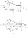
Fig. 10 is a front view of an outer sheath tube for use in cooperation with a guide wire joint. -
Fig. 11 is a cross-sectional view of an outer sheath tube for use in cooperation with the guide wire joint as shown inFig. 10 . -
1 first cover board 2 second cover board 3 connecting part 4 connecting piece 5 rough surface 6 switch 7 first cover board side edge 8 guide wire 9 outer sheath tube 10 guide wire passage 11 guide wire cavity 12 C- shaped groove 13 upper half part 14 lower half part 15 pressure spring 16 outer tube 17 triangular opening - The technical means adopted by the invention for achieving the purpose preset for the invention is further described with reference to the following drawings and preferred embodiments of the invention.
- The invention provides a guide wire joint which comprises a first cover board, a second cover board, a connecting part for connecting the first cover board and the second cover board, and a connecting piece; the connecting piece can connect the guide wire joint to a medical device; a side of the first cover board and a side of the second cover board that are away from the connecting part are in a contact state or a separated state to adjust closing and opening of the guide wire joint; when in the contact state, a guide wire passage is formed between the first cover board and the second cover board so that a guide wire can be allowed to pass through, and the guide wire joint is in a closed state; when in the separated state, the guide wire may be detached from the guide wire joint, with the guide wire joint in an open state.
- According to the guide wire joint provided by the invention, the medical device is a rapid exchange apparatus. The guide wire joint can be used in cooperation with the rapid exchange apparatus to realize the rapid separation of the guide wire and the rapid exchange apparatus, and the specific rapid exchange apparatus can be a papilla incision knife, a stone removing balloon, a radiography tube, a stone removing basket, an expansion balloon, and the like.
- According to the guide wire joint provided by the invention, a side of the first cover board and a side of the second cover board that are away from the connecting part are contacted to form a cylinder-like structure, and the distal end diameter of the cylinder-like structure is smaller than that of the proximal end.
- According to the guide wire joint provided by the invention, the guide wire joint further comprises a switch, and the guide wire joint can be opened by changing or pressing the switch to realize guide wire separation.
- Preferably, the switch is located on a side of the first cover board away from the connecting part and has an arch structure. The switch may also be located between the first cover board and the second cover board, including at least one pressure spring.
- According to the guide wire joint provided by the invention, the first cover board and the second cover board are formed by plastic injection molding.
- According to the guide wire joint provided by the invention, the connecting part is a hinge structure.
- According to the guide wire joint provided by the invention, a rough surface is arranged on the outer surface of the second cover board. The rough surface is a finger clamping position during use such that the friction resistance is increased while the clamping falling off during the opening of the guide wire joint or the separation of the guide wire can be prevented.
- According to the guide wire joint provided by the invention, the rapid exchange apparatus for use in cooperation with the guide wire joint includes an outer sheath tube.
- Preferably, the outer sheath tube includes a guide wire cavity with a C-shaped groove on a side so that the guide wire can penetrate into the guide wire cavity of the outer sheath tube from the guide wire passage of the guide wire joint.
-
Figs. 1 to 9 illustrate a guide wire joint according to an embodiment of the present invention.Figs. 10 to 11 illustrate an outer sheath tube structure according to the present invention. - In a non-limiting embodiment of the present invention, a guide wire joint is as shown in
FIGS. 1-9 , including afirst cover board 1, asecond cover board 2, a connectingpart 3 connecting thefirst cover board 1 and thesecond cover board 2, and a connectingpiece 4. A side of thefirst cover board 1 and a side of thesecond cover board 2 that are away from the connectingpart 3 may be contacted to form a cylinder-like structure. At the moment, the guide wire joint is in a closed state, aguide wire passage 10 is formed between thefirst cover board 1 and thesecond cover board 2 of the guide wire joint, and aguide wire 8 enters the guide wire joint from the proximal end of the guide wire joint through theguide wire passage 10; the distal end diameter of the cylinder-like structure is smaller than that of the proximal end, a side of thefirst cover board 1 and a side of thesecond cover board 2 that are away from theshaft tube 3 can be separated to form an opening, at the time the guide wire joint is in an open state, and theguide wire 8 is separated from the guide wire joint from the opening. - The connecting
piece 4 is arranged on thesecond cover board 2 and fixedly connected with thesecond cover board 2; the connectingpiece 4 can also be formed by protruding the inner sides of thefirst cover board 1 and thesecond cover board 2 outwards, so that when the guide wire joint is closed, the protrusions on the inner sides of the two cover boards are in contact to form a complete connectingpiece 4. The connectingpiece 4 can be connected with the rapid exchange apparatus with the thickness from the proximal end of the guide wire joint to the distal end of the guide wire joint getting gradually reduced. The connectingpiece 4 can form one guiding channel with thefirst cover board 1 while being connected to the rapid exchange apparatus to guide theguide wire 8 . - A
rough surface 5 is arranged on the outer surface of thesecond cover board 2, and therough surface 5 can be a point-shaped protrusion, a stripe-shaped inner concave, and the like. The rough surface is a finger clamping position during use, such that the friction resistance is increased while the clamping falling off during the opening of the guide wire joint or the separation of theguide wire 8 can be prevented. - The guide wire joint can be connected with the
outer tube 16 of the rapid exchange apparatus through the connectingpiece 4, so that theguide wire 8 penetrates through theguide wire passage 10 of the guide wire joint and extends to the distal end, and finally extends out from the distal end of theouter tube 16. The distal end of theouter tube 16 is provided with an opening to facilitate the rapid separation of theguide wire 8 from the guide wire joint when theguide wire 8 is separated from the rapid exchange apparatus, and preferably, the opening arranged at the distal end of theouter tube 16 is atriangular opening 17. When theguide wire 8 enters the guide wire joint from theguide wire passage 10, theguide wire 8 is guided to rapidly enter the cavity of the rapid exchange apparatus and extends out of the distal end outlet of the rapid exchange apparatus to play a guiding role. When theguide wire 8 is retained within theguide wire cavity 11, the distal end of thetriangular opening 17 contacts to retain theguide wire 8 within theguide wire cavity 11. When theguide wire 8 is detached from the rapid exchange apparatus, pulled by a certain force, theguide wire 8 is caused to penetrate through the distal end of thetriangular opening 17, thereby separating theguide wire 8 from the guide wire joint. - In particular, the
outer tube 16 can be designed to be connected to theouter sheath tube 9, wherein one side of theouter sheath tube 9 is provided with a C-shapedgroove 12 so that theguide wire 8 can penetrate from theguide wire passage 10 of the guide wire joint into theguide wire cavity 11 of theouter sheath tube 9. The outer diameter of theouter sheath tube 9 can be designed to be equal to or slightly smaller than the inner diameter of the distal end of the guide wire joint, so that when the guide wire joint is closed, theguide wire 8 can be smoothly inserted into theguide wire cavity 11 of theouter sheath tube 9 from theguide wire passage 10 of the guide wire joint in a better way, reaches the distal end of the rapid exchange apparatus along theguide wire cavity 11, and extends out from the distal end outlet of the rapid exchange apparatus. So that the effect of accurately guiding the advancing direction of theguide wire 8 is achieved and the penetration efficiency of theguide wire 8 is effectively improved. - The connecting
part 3 in the guide wire joint can be a hinge structure to fixedly connect thefirst cover board 1 to thesecond cover board 2. - The guide wire joint also includes a
switch 6 that opens theguide wire passage 10 by changing or pressing to form one opening. When the guide wire joint is opened, theguide wire 8 is separated from the opening of the guide wire joint and the rapid exchange apparatus, thereby achieving rapid exchange. - The
switch 6 can be located on oneside edge 7 of thefirst cover board 1 away from the connectingpart 3, and has an arch structure. Specifically, it arches out towards the outer side of the guide wire joint to form an arc surface. When the guide wire joint is opened, by changing theswitch 6, theside edge 7 of the first cover board is gradually moved away from thesecond cover board 2 to form an opening, and theguide wire 8 arranged in the guide wire joint is separated from the guide wire joint from the opening. - The
switch 6 can also be located between thefirst cover board 1 and thesecond cover board 2 and comprises at least onepressure spring 15. Thefirst cover board 1 of the guide wire joint can be opened to form an opening by pressing thesecond cover board 2 of the guide wire joint, and theguide wire 8 arranged in the guide wire joint is released from the opening. - Therefore, the guide wire joint of the invention is simple and convenient to operate. The guide wire joint can be opened only by changing or pressing the
switch 6, and theguide wire 8 is thus separated from the guide wire joint, so that theguide wire 8 is rapidly separated from the rapid exchange apparatus to the far end portion of the rapid exchange apparatus. It is suitable for the rapid exchange process of the rapid exchange apparatus, comprising a papilla incision knife, a stone removing balloon, a radiography tube, a stone removing basket, an expansion balloon, and the like. In addition, the guide wire joint of the invention effectively shortens the exchange distance of the rapid exchange apparatus for withdrawing from the endoscope along theguide wire 8, realizing the rapid withdrawal of the rapid exchange apparatus and effectively shortening the operation time. - In a non-limiting embodiment of the present invention, as shown in
Figs. 1 and5 which are schematic views of a guide wire joint when it is closed, when the guide wire joint is closed, a side of thefirst cover board 1 and a side of thesecond cover board 2 that are away from the connectingpart 3 are contacted to form a cylinder-like structure. Theguide wire 8 penetrates through the interior of the cylinder-like structure. The distal ends of thefirst cover board 1 and thesecond cover board 2 are gradually closed towards the connectingpart 3, so that the distal end diameter of the cylinder-like structure is smaller than the proximal end diameter. - As shown in
Figs. 1 to 4 , thefirst cover board 1 is an arch structure with a large proximal end diameter and a small distal end diameter. As shown inFig. 3 , the diameter of thefirst cover board 1 is firstly reduced, then unchanged and finally reduced from the proximal end to the distal end. An angled structure with a certain radian is formed at the joint of the proximal end surface of thesecond cover board 2 and the side wall of thesecond cover board 2, and the diameter of thesecond cover board 2 is firstly unchanged and then reduced from the proximal end to the distal end. The initial positions where the diameters of thefirst cover board 1 and thesecond cover board 2 are reduced coincide. Because the distal end diameter of the cylinder-like structure is smaller than the proximal end diameter, when the guide wire joint is closed, theguide wire 8 can be more conveniently transmitted to the distal end of the rapid exchange apparatus after entering the guide wire joint from theguide wire passage 10. As one side of theouter sheath tube 9 of the rapid exchange apparatus is provided with a C-shaped groove structure, theguide wire 8 can be smoothly inserted into theguide wire cavity 11 of theouter sheath tube 9 from theguide wire passage 10 of the guide wire joint so as to enter the distal end of the rapid exchange apparatus, and the exchange distance between theguide wire 8 and the rapid exchange apparatus can be shortened. - A
switch 6 is arranged on oneside 7 of thefirst cover board 1 of the guide wire joint away from the connectingpart 3, and theswitch 6 is arranged on theside edge 7 of the first cover board, and the outer side of the guide wire joint is arched to form an arc surface. When the guide wire joint is opened, by changing theswitch 6, theside edge 7 of the first cover board is gradually moved away from thesecond cover board 2 to form an opening, and theguide wire 8 provided in the guide wire joint is released from the opening. - In another embodiment of the present invention, as shown in
Figs. 5 to 9 , thefirst cover board 1 and thesecond cover board 2 are symmetrical structures. As shown inFigs. 8 to 9 , the connectingpart 3 is located in the middle of thefirst cover board 1 to divide thefirst cover board 1 into a curved upperhalf part 13 and a planar lowerhalf part 14. Theupper half part 13 is an arch structure with a large proximal end diameter and a small distal end diameter. Theupper half part 13, from proximal end to distal end, decreases in diameter first, then does not change, and finally decreases. The lowerhalf part 14 has one planar structure with two symmetrically distributed grooves for arranging apressure spring 15. When thesecond cover board 2 and thefirst cover board 1 which are symmetrical to thefirst cover board 1 are combined in the guide wire joint, a cylinder-like structure is formed, and the guide wire joint is in a closed state. - As shown in
Figs. 5 to 9 , theswitch 6 in the guide wire joint is located between thefirst cover board 1 and thesecond cover board 2 and comprises at least onepressure spring 15, preferably two pressure springs 15 symmetrically distributed between thelower half parts 14 of thefirst cover board 1 and thesecond cover board 2 of the guide wire. By pressing thesecond cover board 2 of the guide wire joint, the distance between thelower half parts 14 of the two cover boards is reduced. Because thefirst cover board 1 and thesecond cover board 2 are connected by the connectingpart 3 provided between theupper half parts 13 and thelower half parts 14, when the distance between the twolower half parts 14 is reduced, theupper half parts 13 tend to move away from each other, so that the guide wire joint opens to form an opening, and theguide wire 8 provided in the guide wire joint is released from the opening. - Referring to
Fig. 7 , which shows the connectingpiece 4 in the guide wire joint, wherein the proximal end tip of which terminates at the proximal end tips of thefirst cover board 1 and thesecond cover board 2, in which case the guide wire joint is clamped on theouter sheath tube 9 or theouter tube 16. The connectingpiece 4 may also be shown inFigs. 8 and9 , wherein the proximal end tip of which is located outside the proximal ends of thefirst cover board 1 and thesecond cover board 2, and the outwardly extending portions are fixedly connected to theouter sheath tube 9 or theouter tube 16. - The above are only the preferred embodiments of the present invention, and do not limit the present invention in any form. Although the present invention has been disclosed as the preferred embodiments, it is not intended to limit the present invention. Any person skilled in the art familiar with the profession, without departing from the scope of the technical solution of the present invention, can use the technical content disclosed above to make some changes or modifications to equivalent embodiments with equivalent changes. Any content that does not deviate from the technical solution of the present invention, and any simple modifications, equivalent changes and modifications made to the above embodiments based on the technical essence of the present invention still fall within the scope of the technical solution of the present invention.
Claims (11)
- A guide wire joint, characterized by comprising a first cover board, a second cover board, a connecting part for connecting the first cover board and the second cover board, and a connecting piece; the connecting piece can connect the guide wire joint to a medical device; a side of the first cover board and a side of the second cover board that are away from the connecting part are in a contact state or a separated state to realize closing and opening of the guide wire joint; when in the contact state, a guide wire passage is formed between the first cover board and the second cover board so that a guide wire can be allowed to pass through, and when in the separated state, the guide wire may be detached from the guide wire joint.
- The guide wire joint of claim 1, characterized in that the medical device is a rapid exchange apparatus and the guide wire joint can be used in cooperation with the rapid exchange apparatus to achieve rapid separation of the guide wire from the rapid exchange apparatus.
- The guide wire joint of claim 1, characterized in that a distal end diameter of a structure formed by contacting sides of the first cover board and the second cover board away from the connecting part is smaller than a proximal end diameter of the structure.
- The guide wire joint of claim 1, characterized in that the guide wire joint further comprises a switch for opening the guide wire joint by changing or pressing the switch to separate the guide wire.
- The guide wire joint of claim 4, characterized in that the switch is located on a side of the first cover board away from the connecting part and has an arch structure.
- The guide wire joint of claim 4, characterized in that the switch is located between the first cover board and the second cover board and comprises a pressure spring.
- The guide wire joint of claim 1, characterized in that the first cover board and the second cover board are formed by plastic injection molding.
- The guide wire joint of claim 1, characterized in that the connecting part is a hinge structure.
- The guide wire joint of claim 1, characterized in that the second cover board has a rough surface on an outer surface thereof.
- The guide wire joint of claim 2, characterized in that the rapid exchange apparatus used in cooperation with the guide wire joint comprises an outer sheath tube.
- The guide wire joint of claim 10, characterized in that the outer sheath tube comprises a guide wire cavity with a C-shaped groove formed in a side thereof.
Applications Claiming Priority (2)
| Application Number | Priority Date | Filing Date | Title |
|---|---|---|---|
| CN201811060589.9A CN109044525B (en) | 2018-09-11 | 2018-09-11 | Guide wire joint |
| PCT/CN2019/094692 WO2020052331A1 (en) | 2018-09-11 | 2019-07-04 | Guide wire joint |
Publications (4)
| Publication Number | Publication Date |
|---|---|
| EP3821935A1 true EP3821935A1 (en) | 2021-05-19 |
| EP3821935A4 EP3821935A4 (en) | 2022-04-20 |
| EP3821935C0 EP3821935C0 (en) | 2025-06-18 |
| EP3821935B1 EP3821935B1 (en) | 2025-06-18 |
Family
ID=64760345
Family Applications (1)
| Application Number | Title | Priority Date | Filing Date |
|---|---|---|---|
| EP19860360.7A Active EP3821935B1 (en) | 2018-09-11 | 2019-07-04 | Guide wire joint |
Country Status (7)
| Country | Link |
|---|---|
| US (1) | US20210186589A1 (en) |
| EP (1) | EP3821935B1 (en) |
| JP (1) | JP7257426B2 (en) |
| CN (1) | CN109044525B (en) |
| AU (1) | AU2019339565B2 (en) |
| CA (1) | CA3111036C (en) |
| WO (1) | WO2020052331A1 (en) |
Families Citing this family (4)
| Publication number | Priority date | Publication date | Assignee | Title |
|---|---|---|---|---|
| CN109044525B (en) * | 2018-09-11 | 2024-06-04 | 南微医学科技股份有限公司 | Guide wire joint |
| WO2022074723A1 (en) | 2020-10-06 | 2022-04-14 | オリンパス株式会社 | Treatment tool for endoscope and method for using treatment tool for endoscope |
| CN116020041A (en) * | 2022-12-08 | 2023-04-28 | 北京管桥医疗科技有限公司 | Guide wire threading device and guide wire threading method |
| CN119524292B (en) * | 2025-01-02 | 2025-10-10 | 深圳科思明德医疗科技有限公司 | A nipple incision knife and a nipple incision system |
Family Cites Families (27)
| Publication number | Priority date | Publication date | Assignee | Title |
|---|---|---|---|---|
| DE3804944A1 (en) * | 1988-02-18 | 1989-08-31 | Braun Melsungen Ag | DEVICE FOR THREADING A GUIDE WIRE INTO A CATHETER |
| MY103860A (en) * | 1988-06-13 | 1993-09-30 | Bard Inc C R | Guidewire extension with self-latching detachable connector |
| GB9309142D0 (en) * | 1993-05-04 | 1993-06-16 | Gyrus Medical Ltd | Laparoscopic instrument |
| US5836306A (en) * | 1994-12-23 | 1998-11-17 | Bard Connaught | Exchange accessory for use with a monorail catheter |
| US5921971A (en) * | 1996-09-13 | 1999-07-13 | Boston Scientific Corporation | Single operator exchange biliary catheter |
| US6606515B1 (en) * | 1996-09-13 | 2003-08-12 | Scimed Life Systems, Inc. | Guide wire insertion and re-insertion tools and methods of use |
| US5830183A (en) * | 1997-06-30 | 1998-11-03 | Schneider (Usa) Inc | Clip device for vascular catheter |
| US6190333B1 (en) * | 1999-10-15 | 2001-02-20 | Mark Ii Research And Development Corp. | Threader device for threading a guidewire into a catheter |
| US6264672B1 (en) * | 1999-10-25 | 2001-07-24 | Biopsy Sciences, Llc | Emboli capturing device |
| DE60114857T2 (en) * | 2000-08-14 | 2006-09-07 | Boston Scientific Ltd., Saint Michael | Steerable sphincterotome |
| US20020072712A1 (en) * | 2000-10-12 | 2002-06-13 | Nool Jeffrey A. | Medical wire introducer and protective sheath |
| US7717865B2 (en) * | 2003-09-30 | 2010-05-18 | Boston Scientific Scimed, Inc. | Side loading wire torquing device |
| US7815601B2 (en) * | 2007-02-05 | 2010-10-19 | Boston Scientific Scimed, Inc. | Rapid exchange enteral stent delivery system |
| CN102316923A (en) * | 2008-10-10 | 2012-01-11 | 奈科斯恩麦德系统有限公司 | Practice thrift stock's conduit system |
| US8636728B2 (en) * | 2009-03-11 | 2014-01-28 | Boston Scientific Scimed, Inc. | Apparatus and methods for retracting a catheter balloon |
| CN101897630A (en) * | 2010-08-16 | 2010-12-01 | 南京微创医学科技有限公司 | bendable compliant intraluminal stent |
| CN102512272A (en) * | 2011-12-31 | 2012-06-27 | 广州曼翔医疗器械有限公司 | Paranasal sinus holder and special conveying appliance thereof |
| US20140194849A1 (en) * | 2013-01-07 | 2014-07-10 | Cook Medical Technologies Llc | Removable clip for catheter |
| US9050439B1 (en) * | 2013-11-21 | 2015-06-09 | Medtronic Ardian Luxembourg S.A.R.L. | Catheter loading device and method of using same |
| CN103750901B (en) * | 2014-02-14 | 2016-01-20 | 徐美东 | A kind of Multifunctional high-frequency incision knife |
| EP3115014B1 (en) * | 2014-03-04 | 2019-07-24 | Olympus Corporation | Endoscopic treatment tool |
| JP2016042992A (en) * | 2014-08-21 | 2016-04-04 | テルモ株式会社 | Blood vessel ablation device |
| US9877832B2 (en) * | 2014-08-22 | 2018-01-30 | Medtronic Vascular, Inc. | Rapid exchange transcatheter valve delivery system |
| JP2016106813A (en) * | 2014-12-05 | 2016-06-20 | 株式会社ジェイ・エム・エス | Guide wire introduction assist tool |
| CN206102695U (en) * | 2016-07-26 | 2017-04-19 | 上海加奇生物科技苏州有限公司 | Artery conveying system |
| CN209301303U (en) * | 2018-09-11 | 2019-08-27 | 南京微创医学科技股份有限公司 | A kind of seal wire connector |
| CN109044525B (en) * | 2018-09-11 | 2024-06-04 | 南微医学科技股份有限公司 | Guide wire joint |
-
2018
- 2018-09-11 CN CN201811060589.9A patent/CN109044525B/en active Active
-
2019
- 2019-07-04 US US17/270,993 patent/US20210186589A1/en not_active Abandoned
- 2019-07-04 EP EP19860360.7A patent/EP3821935B1/en active Active
- 2019-07-04 CA CA3111036A patent/CA3111036C/en active Active
- 2019-07-04 JP JP2020571789A patent/JP7257426B2/en active Active
- 2019-07-04 WO PCT/CN2019/094692 patent/WO2020052331A1/en not_active Ceased
- 2019-07-04 AU AU2019339565A patent/AU2019339565B2/en active Active
Also Published As
| Publication number | Publication date |
|---|---|
| CA3111036A1 (en) | 2020-03-19 |
| AU2019339565A1 (en) | 2021-03-04 |
| US20210186589A1 (en) | 2021-06-24 |
| JP7257426B2 (en) | 2023-04-13 |
| EP3821935A4 (en) | 2022-04-20 |
| EP3821935C0 (en) | 2025-06-18 |
| AU2019339565B2 (en) | 2022-07-21 |
| WO2020052331A1 (en) | 2020-03-19 |
| CN109044525A (en) | 2018-12-21 |
| JP2021529580A (en) | 2021-11-04 |
| EP3821935B1 (en) | 2025-06-18 |
| CN109044525B (en) | 2024-06-04 |
| CA3111036C (en) | 2024-06-18 |
Similar Documents
| Publication | Publication Date | Title |
|---|---|---|
| CA3111036C (en) | Guide wire joint | |
| EP2091442B1 (en) | Biopsy collection device | |
| CA3111301C (en) | Stone extraction basket and double lumen end cap for stone extraction basket | |
| US20210015349A1 (en) | Medical device | |
| US20150173785A1 (en) | Apparatus and method for effecting at least one anatomical structure | |
| CN209301303U (en) | A kind of seal wire connector | |
| CN204723173U (en) | A kind of sphincterotomy cutter with limiting tooth handle | |
| US10499978B2 (en) | Dissecting device and dissecting system | |
| JP2006333943A (en) | Submucosa peeling treatment device and system | |
| KR20150116687A (en) | Papillotome for Endoscopic Retrograde Cholangio-Pancreatography | |
| JP7173455B2 (en) | Medical perforation cautery device | |
| CN107343814A (en) | A kind of incision knife | |
| CN201631253U (en) | Oral-nasal catheter extraction device | |
| CN109512505B (en) | Limiting device and using method thereof | |
| KR102569595B1 (en) | Endoscopic catheter | |
| KR102593656B1 (en) | Medical catheter | |
| CN113349950A (en) | Locking structure and incision sword | |
| CN205144720U (en) | Novel nipple sphincter opens sword | |
| CN223248303U (en) | Disposable endoscopic gastric wall-bile and pancreatic duct dilator | |
| JP2017153605A (en) | Peeling device and peeling system | |
| CN201500370U (en) | A multifunctional urethral dilator | |
| JP2017153603A (en) | Peeling device | |
| JP2017153601A (en) | Peeling device | |
| WO2017039390A1 (en) | Flexible ablation mechanism |
Legal Events
| Date | Code | Title | Description |
|---|---|---|---|
| STAA | Information on the status of an ep patent application or granted ep patent |
Free format text: STATUS: THE INTERNATIONAL PUBLICATION HAS BEEN MADE |
|
| PUAI | Public reference made under article 153(3) epc to a published international application that has entered the european phase |
Free format text: ORIGINAL CODE: 0009012 |
|
| STAA | Information on the status of an ep patent application or granted ep patent |
Free format text: STATUS: REQUEST FOR EXAMINATION WAS MADE |
|
| 17P | Request for examination filed |
Effective date: 20210209 |
|
| AK | Designated contracting states |
Kind code of ref document: A1 Designated state(s): AL AT BE BG CH CY CZ DE DK EE ES FI FR GB GR HR HU IE IS IT LI LT LU LV MC MK MT NL NO PL PT RO RS SE SI SK SM TR |
|
| DAV | Request for validation of the european patent (deleted) | ||
| DAX | Request for extension of the european patent (deleted) | ||
| A4 | Supplementary search report drawn up and despatched |
Effective date: 20220321 |
|
| RIC1 | Information provided on ipc code assigned before grant |
Ipc: A61B 18/00 20060101ALN20220315BHEP Ipc: A61B 18/14 20060101ALN20220315BHEP Ipc: A61M 25/09 20060101AFI20220315BHEP |
|
| STAA | Information on the status of an ep patent application or granted ep patent |
Free format text: STATUS: EXAMINATION IS IN PROGRESS |
|
| 17Q | First examination report despatched |
Effective date: 20230921 |
|
| GRAP | Despatch of communication of intention to grant a patent |
Free format text: ORIGINAL CODE: EPIDOSNIGR1 |
|
| STAA | Information on the status of an ep patent application or granted ep patent |
Free format text: STATUS: GRANT OF PATENT IS INTENDED |
|
| RIC1 | Information provided on ipc code assigned before grant |
Ipc: A61B 18/00 20060101ALN20250109BHEP Ipc: A61B 18/14 20060101ALN20250109BHEP Ipc: A61M 25/09 20060101AFI20250109BHEP |
|
| INTG | Intention to grant announced |
Effective date: 20250127 |
|
| GRAS | Grant fee paid |
Free format text: ORIGINAL CODE: EPIDOSNIGR3 |
|
| GRAA | (expected) grant |
Free format text: ORIGINAL CODE: 0009210 |
|
| STAA | Information on the status of an ep patent application or granted ep patent |
Free format text: STATUS: THE PATENT HAS BEEN GRANTED |
|
| AK | Designated contracting states |
Kind code of ref document: B1 Designated state(s): AL AT BE BG CH CY CZ DE DK EE ES FI FR GB GR HR HU IE IS IT LI LT LU LV MC MK MT NL NO PL PT RO RS SE SI SK SM TR |
|
| REG | Reference to a national code |
Ref country code: GB Ref legal event code: FG4D |
|
| REG | Reference to a national code |
Ref country code: CH Ref legal event code: EP |
|
| REG | Reference to a national code |
Ref country code: DE Ref legal event code: R096 Ref document number: 602019071364 Country of ref document: DE |
|
| REG | Reference to a national code |
Ref country code: CH Ref legal event code: EP |
|
| REG | Reference to a national code |
Ref country code: IE Ref legal event code: FG4D |
|
| U01 | Request for unitary effect filed |
Effective date: 20250716 |
|
| U07 | Unitary effect registered |
Designated state(s): AT BE BG DE DK EE FI FR IT LT LU LV MT NL PT RO SE SI Effective date: 20250722 |
|
| U20 | Renewal fee for the european patent with unitary effect paid |
Year of fee payment: 7 Effective date: 20250722 |
|
| PG25 | Lapsed in a contracting state [announced via postgrant information from national office to epo] |
Ref country code: GR Free format text: LAPSE BECAUSE OF FAILURE TO SUBMIT A TRANSLATION OF THE DESCRIPTION OR TO PAY THE FEE WITHIN THE PRESCRIBED TIME-LIMIT Effective date: 20250919 Ref country code: NO Free format text: LAPSE BECAUSE OF FAILURE TO SUBMIT A TRANSLATION OF THE DESCRIPTION OR TO PAY THE FEE WITHIN THE PRESCRIBED TIME-LIMIT Effective date: 20250918 |
|
| PGFP | Annual fee paid to national office [announced via postgrant information from national office to epo] |
Ref country code: GB Payment date: 20250722 Year of fee payment: 7 |
|
| PG25 | Lapsed in a contracting state [announced via postgrant information from national office to epo] |
Ref country code: HR Free format text: LAPSE BECAUSE OF FAILURE TO SUBMIT A TRANSLATION OF THE DESCRIPTION OR TO PAY THE FEE WITHIN THE PRESCRIBED TIME-LIMIT Effective date: 20250618 |
|
| PG25 | Lapsed in a contracting state [announced via postgrant information from national office to epo] |
Ref country code: RS Free format text: LAPSE BECAUSE OF FAILURE TO SUBMIT A TRANSLATION OF THE DESCRIPTION OR TO PAY THE FEE WITHIN THE PRESCRIBED TIME-LIMIT Effective date: 20250918 |
|
| PG25 | Lapsed in a contracting state [announced via postgrant information from national office to epo] |
Ref country code: IS Free format text: LAPSE BECAUSE OF FAILURE TO SUBMIT A TRANSLATION OF THE DESCRIPTION OR TO PAY THE FEE WITHIN THE PRESCRIBED TIME-LIMIT Effective date: 20251018 |
|
| PG25 | Lapsed in a contracting state [announced via postgrant information from national office to epo] |
Ref country code: SM Free format text: LAPSE BECAUSE OF FAILURE TO SUBMIT A TRANSLATION OF THE DESCRIPTION OR TO PAY THE FEE WITHIN THE PRESCRIBED TIME-LIMIT Effective date: 20250618 |
|
| PG25 | Lapsed in a contracting state [announced via postgrant information from national office to epo] |
Ref country code: CZ Free format text: LAPSE BECAUSE OF FAILURE TO SUBMIT A TRANSLATION OF THE DESCRIPTION OR TO PAY THE FEE WITHIN THE PRESCRIBED TIME-LIMIT Effective date: 20250618 |
|
| PG25 | Lapsed in a contracting state [announced via postgrant information from national office to epo] |
Ref country code: PL Free format text: LAPSE BECAUSE OF FAILURE TO SUBMIT A TRANSLATION OF THE DESCRIPTION OR TO PAY THE FEE WITHIN THE PRESCRIBED TIME-LIMIT Effective date: 20250618 |
|
| PG25 | Lapsed in a contracting state [announced via postgrant information from national office to epo] |
Ref country code: SK Free format text: LAPSE BECAUSE OF FAILURE TO SUBMIT A TRANSLATION OF THE DESCRIPTION OR TO PAY THE FEE WITHIN THE PRESCRIBED TIME-LIMIT Effective date: 20250618 |
|
| PG25 | Lapsed in a contracting state [announced via postgrant information from national office to epo] |
Ref country code: ES Free format text: LAPSE BECAUSE OF FAILURE TO SUBMIT A TRANSLATION OF THE DESCRIPTION OR TO PAY THE FEE WITHIN THE PRESCRIBED TIME-LIMIT Effective date: 20250618 |
|
| REG | Reference to a national code |
Ref country code: CH Ref legal event code: H13 Free format text: ST27 STATUS EVENT CODE: U-0-0-H10-H13 (AS PROVIDED BY THE NATIONAL OFFICE) Effective date: 20260224 |
|
| PG25 | Lapsed in a contracting state [announced via postgrant information from national office to epo] |
Ref country code: MC Free format text: LAPSE BECAUSE OF FAILURE TO SUBMIT A TRANSLATION OF THE DESCRIPTION OR TO PAY THE FEE WITHIN THE PRESCRIBED TIME-LIMIT Effective date: 20250618 |
|
| PG25 | Lapsed in a contracting state [announced via postgrant information from national office to epo] |
Ref country code: CH Free format text: LAPSE BECAUSE OF NON-PAYMENT OF DUE FEES Effective date: 20250731 |
|
| PLBE | No opposition filed within time limit |
Free format text: ORIGINAL CODE: 0009261 |
|
| STAA | Information on the status of an ep patent application or granted ep patent |
Free format text: STATUS: NO OPPOSITION FILED WITHIN TIME LIMIT |
|
| REG | Reference to a national code |
Ref country code: CH Ref legal event code: L10 Free format text: ST27 STATUS EVENT CODE: U-0-0-L10-L00 (AS PROVIDED BY THE NATIONAL OFFICE) Effective date: 20260430 |