EP3760251A1 - Medicating appliance and liquid medicine administering system - Google Patents
Medicating appliance and liquid medicine administering system Download PDFInfo
- Publication number
- EP3760251A1 EP3760251A1 EP19777665.1A EP19777665A EP3760251A1 EP 3760251 A1 EP3760251 A1 EP 3760251A1 EP 19777665 A EP19777665 A EP 19777665A EP 3760251 A1 EP3760251 A1 EP 3760251A1
- Authority
- EP
- European Patent Office
- Prior art keywords
- medicinal solution
- tube
- administering
- end part
- puncture
- Prior art date
- Legal status (The legal status is an assumption and is not a legal conclusion. Google has not performed a legal analysis and makes no representation as to the accuracy of the status listed.)
- Withdrawn
Links
- 239000003814 drug Substances 0.000 title 1
- 239000007788 liquid Substances 0.000 title 1
- 238000004891 communication Methods 0.000 claims abstract description 32
- 239000000853 adhesive Substances 0.000 description 6
- 230000001070 adhesive effect Effects 0.000 description 6
- 229920001971 elastomer Polymers 0.000 description 6
- 239000000463 material Substances 0.000 description 6
- 238000010586 diagram Methods 0.000 description 4
- 239000000806 elastomer Substances 0.000 description 4
- 229920005989 resin Polymers 0.000 description 4
- 239000011347 resin Substances 0.000 description 4
- 238000007789 sealing Methods 0.000 description 4
- 239000000470 constituent Substances 0.000 description 3
- 239000005062 Polybutadiene Substances 0.000 description 2
- 210000001015 abdomen Anatomy 0.000 description 2
- 230000000694 effects Effects 0.000 description 2
- 238000003780 insertion Methods 0.000 description 2
- 230000037431 insertion Effects 0.000 description 2
- 239000002184 metal Substances 0.000 description 2
- 230000002093 peripheral effect Effects 0.000 description 2
- 229920002857 polybutadiene Polymers 0.000 description 2
- -1 polyethylene Polymers 0.000 description 2
- 230000001681 protective effect Effects 0.000 description 2
- 239000005060 rubber Substances 0.000 description 2
- 210000000689 upper leg Anatomy 0.000 description 2
- 239000004952 Polyamide Substances 0.000 description 1
- 239000004698 Polyethylene Substances 0.000 description 1
- 239000004743 Polypropylene Substances 0.000 description 1
- 238000005452 bending Methods 0.000 description 1
- 229920001577 copolymer Polymers 0.000 description 1
- 230000008878 coupling Effects 0.000 description 1
- 238000010168 coupling process Methods 0.000 description 1
- 238000005859 coupling reaction Methods 0.000 description 1
- 239000002934 diuretic Substances 0.000 description 1
- 230000001882 diuretic effect Effects 0.000 description 1
- 239000005038 ethylene vinyl acetate Substances 0.000 description 1
- 229920000126 latex Polymers 0.000 description 1
- 239000004084 narcotic analgesic agent Substances 0.000 description 1
- 229920001200 poly(ethylene-vinyl acetate) Polymers 0.000 description 1
- 229920002647 polyamide Polymers 0.000 description 1
- 229920000728 polyester Polymers 0.000 description 1
- 229920000573 polyethylene Polymers 0.000 description 1
- 229920000098 polyolefin Polymers 0.000 description 1
- 229920001155 polypropylene Polymers 0.000 description 1
- 229920003225 polyurethane elastomer Polymers 0.000 description 1
- 239000004800 polyvinyl chloride Substances 0.000 description 1
- 229920000915 polyvinyl chloride Polymers 0.000 description 1
- 102000004169 proteins and genes Human genes 0.000 description 1
- 108090000623 proteins and genes Proteins 0.000 description 1
- 229920002379 silicone rubber Polymers 0.000 description 1
- 239000004945 silicone rubber Substances 0.000 description 1
- 239000000758 substrate Substances 0.000 description 1
- 229920005992 thermoplastic resin Polymers 0.000 description 1
Images


Classifications
-
- A—HUMAN NECESSITIES
- A61—MEDICAL OR VETERINARY SCIENCE; HYGIENE
- A61M—DEVICES FOR INTRODUCING MEDIA INTO, OR ONTO, THE BODY; DEVICES FOR TRANSDUCING BODY MEDIA OR FOR TAKING MEDIA FROM THE BODY; DEVICES FOR PRODUCING OR ENDING SLEEP OR STUPOR
- A61M5/00—Devices for bringing media into the body in a subcutaneous, intra-vascular or intramuscular way; Accessories therefor, e.g. filling or cleaning devices, arm-rests
- A61M5/14—Infusion devices, e.g. infusing by gravity; Blood infusion; Accessories therefor
- A61M5/158—Needles for infusions; Accessories therefor, e.g. for inserting infusion needles, or for holding them on the body
-
- A—HUMAN NECESSITIES
- A61—MEDICAL OR VETERINARY SCIENCE; HYGIENE
- A61M—DEVICES FOR INTRODUCING MEDIA INTO, OR ONTO, THE BODY; DEVICES FOR TRANSDUCING BODY MEDIA OR FOR TAKING MEDIA FROM THE BODY; DEVICES FOR PRODUCING OR ENDING SLEEP OR STUPOR
- A61M5/00—Devices for bringing media into the body in a subcutaneous, intra-vascular or intramuscular way; Accessories therefor, e.g. filling or cleaning devices, arm-rests
- A61M5/14—Infusion devices, e.g. infusing by gravity; Blood infusion; Accessories therefor
- A61M5/1413—Modular systems comprising interconnecting elements
-
- A—HUMAN NECESSITIES
- A61—MEDICAL OR VETERINARY SCIENCE; HYGIENE
- A61M—DEVICES FOR INTRODUCING MEDIA INTO, OR ONTO, THE BODY; DEVICES FOR TRANSDUCING BODY MEDIA OR FOR TAKING MEDIA FROM THE BODY; DEVICES FOR PRODUCING OR ENDING SLEEP OR STUPOR
- A61M5/00—Devices for bringing media into the body in a subcutaneous, intra-vascular or intramuscular way; Accessories therefor, e.g. filling or cleaning devices, arm-rests
- A61M5/14—Infusion devices, e.g. infusing by gravity; Blood infusion; Accessories therefor
- A61M5/142—Pressure infusion, e.g. using pumps
- A61M5/145—Pressure infusion, e.g. using pumps using pressurised reservoirs, e.g. pressurised by means of pistons
-
- A—HUMAN NECESSITIES
- A61—MEDICAL OR VETERINARY SCIENCE; HYGIENE
- A61M—DEVICES FOR INTRODUCING MEDIA INTO, OR ONTO, THE BODY; DEVICES FOR TRANSDUCING BODY MEDIA OR FOR TAKING MEDIA FROM THE BODY; DEVICES FOR PRODUCING OR ENDING SLEEP OR STUPOR
- A61M5/00—Devices for bringing media into the body in a subcutaneous, intra-vascular or intramuscular way; Accessories therefor, e.g. filling or cleaning devices, arm-rests
- A61M5/14—Infusion devices, e.g. infusing by gravity; Blood infusion; Accessories therefor
- A61M5/162—Needle sets, i.e. connections by puncture between reservoir and tube ; Connections between reservoir and tube
-
- A—HUMAN NECESSITIES
- A61—MEDICAL OR VETERINARY SCIENCE; HYGIENE
- A61M—DEVICES FOR INTRODUCING MEDIA INTO, OR ONTO, THE BODY; DEVICES FOR TRANSDUCING BODY MEDIA OR FOR TAKING MEDIA FROM THE BODY; DEVICES FOR PRODUCING OR ENDING SLEEP OR STUPOR
- A61M5/00—Devices for bringing media into the body in a subcutaneous, intra-vascular or intramuscular way; Accessories therefor, e.g. filling or cleaning devices, arm-rests
- A61M5/14—Infusion devices, e.g. infusing by gravity; Blood infusion; Accessories therefor
- A61M5/142—Pressure infusion, e.g. using pumps
- A61M5/14244—Pressure infusion, e.g. using pumps adapted to be carried by the patient, e.g. portable on the body
- A61M5/14248—Pressure infusion, e.g. using pumps adapted to be carried by the patient, e.g. portable on the body of the skin patch type
- A61M2005/14252—Pressure infusion, e.g. using pumps adapted to be carried by the patient, e.g. portable on the body of the skin patch type with needle insertion means
-
- A—HUMAN NECESSITIES
- A61—MEDICAL OR VETERINARY SCIENCE; HYGIENE
- A61M—DEVICES FOR INTRODUCING MEDIA INTO, OR ONTO, THE BODY; DEVICES FOR TRANSDUCING BODY MEDIA OR FOR TAKING MEDIA FROM THE BODY; DEVICES FOR PRODUCING OR ENDING SLEEP OR STUPOR
- A61M5/00—Devices for bringing media into the body in a subcutaneous, intra-vascular or intramuscular way; Accessories therefor, e.g. filling or cleaning devices, arm-rests
- A61M5/14—Infusion devices, e.g. infusing by gravity; Blood infusion; Accessories therefor
- A61M5/158—Needles for infusions; Accessories therefor, e.g. for inserting infusion needles, or for holding them on the body
- A61M2005/1587—Needles for infusions; Accessories therefor, e.g. for inserting infusion needles, or for holding them on the body suitable for being connected to an infusion line after insertion into a patient
-
- A—HUMAN NECESSITIES
- A61—MEDICAL OR VETERINARY SCIENCE; HYGIENE
- A61M—DEVICES FOR INTRODUCING MEDIA INTO, OR ONTO, THE BODY; DEVICES FOR TRANSDUCING BODY MEDIA OR FOR TAKING MEDIA FROM THE BODY; DEVICES FOR PRODUCING OR ENDING SLEEP OR STUPOR
- A61M5/00—Devices for bringing media into the body in a subcutaneous, intra-vascular or intramuscular way; Accessories therefor, e.g. filling or cleaning devices, arm-rests
- A61M5/14—Infusion devices, e.g. infusing by gravity; Blood infusion; Accessories therefor
- A61M5/142—Pressure infusion, e.g. using pumps
- A61M5/14244—Pressure infusion, e.g. using pumps adapted to be carried by the patient, e.g. portable on the body
- A61M5/14248—Pressure infusion, e.g. using pumps adapted to be carried by the patient, e.g. portable on the body of the skin patch type
Definitions
- the present invention relates to an administering instrument and a medicinal solution administering system including the administering instrument and a medicinal solution administering device.
- a syringe pump-type medicinal solution administering device which administers a medicinal solution filled in a medicinal solution container to a living body by a pressing action of a plunger. Further, in administering a medicinal solution with a medicinal solution administering device of this type, an administering instrument is sometimes used which includes a puncture part (cannula housing) connected to the medicinal solution administering device via a predetermined connector and tube.
- the puncture part provided in the administering instrument has a contact surface (bottom surface) that comes into contact with a body surface of a user. Further, the puncture part holds a needle tube arranged so as to project from the contact surface. The needle tube held by the puncture part supplies a medicinal solution fed from the medicinal solution container via a tube or the like to the living body with the needle tube puncturing the living body.
- Patent Literature 1 JP 2009-233388 A
- the administering instrument is attached to the body surface of the user via the contact surface of the puncture part while the medicinal solution is administered to the living body.
- the medicinal solution administering device is attached to the body surface of the user through the contact surface (bottom surface) of the housing in which each constituent member of the medicinal solution administering device is assembled. Therefore, while the medicinal solution is administered to the user, the puncture part of the administering instrument and the medicinal solution administering device are attached to the body surface of the user with the puncture part and the medicinal solution administering device connected to each other via the tube.
- the puncture part is pulled toward the medicinal solution administering device via the tube.
- a force that lifts the puncture part from the body surface acts on the puncture part, which sometimes causes the puncture part to come off the body surface. Further, this possibly causes the needle tube held by the puncture part to come out of the living body.
- the medicinal solution administering device and the puncture part are attached to a curved body surface (for example, abdomen, thigh, and so on) or where a thin puncture part is attached to the body surface and then a deviation (difference) in the height direction occurs between a position of the contact surface of the puncture part and a position of the contact surface of the medicinal solution administering device, a force that lifts the puncture part from the body surface via the tube is likely to act on the puncture part, which increases the possibility that the needle tube is removed.
- a curved body surface for example, abdomen, thigh, and so on
- a deviation in the height direction
- the present invention has been made in view of the above issues, and an object of the present invention is to provide an administering instrument that is capable of preventing a needle tube from coming out of a living body during administration of a medicinal solution, and to provide a medicinal solution administering system including the administering instrument and a medicinal solution administering device.
- An administering instrument is an administering instrument connectable to a medicinal solution administering device including a medicinal solution container in which a medicinal solution is filled.
- the administering instrument includes a connector that includes a communication part capable of communicating with a lumen of the medicinal solution container and is connectable to the medicinal solution administering device; a needle tube that punctures a living body; a puncture part including a contact surface that is provided in a lower end to contact a living body surface of the living body, a needle holding part that is provided above the contact surface to hold the needle tube so that a tip of the needle tube projects from the contact surface, and a communication passage communicating with a lumen of the needle tube; and a tube that includes a first end part connected to the puncture part, a second end part connected to the connector, and a tube body communicating from the first end part to the second end part and is configured to supply the medicinal solution from the lumen of the medicinal solution container to the needle tube via the communication part of the connector and the communication passage of the puncture part.
- the tube body has
- a medicinal solution administering system includes a medicinal solution administering device having a medicinal solution container, a housing that holds the medicinal solution container, and a plunger that pushes out the medicinal solution in the medicinal solution container to the tube.
- the administering instrument and the medicinal solution administering system of the present invention it is possible to prevent the needle tube from coming out of a living body during administration of a medicinal solution.
- Figs. 1 to 5 are diagrams for explaining a medicinal solution administering system 10, a medicinal solution administering device 100, and an administering instrument 200 according to the first embodiment.
- an arrow X indicates a "longitudinal direction (extending direction of a tube 240)" of the medicinal solution administering device 100 and the administering instrument 200
- an arrow Y indicates a "width direction (depth direction)” of the medicinal solution administering device 100 and the administering instrument 200
- an arrow Z indicates a "height direction (thickness direction of a puncture part 230)" of the medicinal solution administering device 100 and the administering instrument 200.
- a sectional view illustrated in Fig. 3 is a longitudinal sectional view (sectional view taken along the section X-Z) of the medicinal solution administering device 100 and the administering instrument 200.
- the medicinal solution administering system 10 is used to administer a medicinal solution to a living body. As illustrated in Fig. 1 , the medicinal solution administering system 10 includes the medicinal solution administering device 100 and the administering instrument 200.
- the medicinal solution administering device 100 and the puncture part 230 of the administering instrument 200 are attached to a body surface H of a user.
- the location of the body of the user to which the medicinal solution administering device 100 and the puncture part 230 are attached is not particularly limited, but is the abdomen or thigh for example.
- the medicinal solution administering system 10 can continuously administer, for example, a medicinal solution (not shown) filled in a medicinal solution container 110 of the medicinal solution administering device 100 to a living body over a relatively long time (for example, a few minutes to a few hours) by a pressing action of a plunger 130.
- the medicinal solution administering system 10 may intermittently administer the medicinal solution to the living body.
- the medicinal solution administering device 100 includes the medicinal solution container 110 in which a medicinal solution is filled, a housing 120 for holding the medicinal solution container therein, and the plunger 130 for pushing out the medicinal solution held in the medicinal solution container 110 to the tube 240 described later.
- the medicinal solution container 110 has a cylindrical body including a lumen 111 in which the medicinal solution is filled.
- a tip of the plunger 130 is inserted into the medicinal solution container 110.
- a gasket 131 is disposed at the tip of the plunger 130.
- the gasket 131 can be made of, for example, a rubber material or a resin material such as an elastomer.
- the outer peripheral portion of the gasket 131 liquid-tightly contacts the inner peripheral surface of the medicinal solution container 110, which liquid-tightly seals a proximal end side of the gasket 131.
- the medicinal solution container 110 is constituted by a so-called pre-filled type medicinal solution container.
- the medicinal solution is therefore filled, in advance, in the lumen 111 of the medicinal solution container 110.
- the medicinal solution include a protein preparation, a narcotic analgesic, and a diuretic.
- a sealing member 113 for preventing leakage of the medicinal solution is provided in a tip opening (discharge port) of the medicinal solution container 110.
- the tip opening of the medicinal solution container 110 is disposed so as to project to the outside of the housing 120.
- the plunger 130 is configured to be movable forward with respect to the medicinal solution container 110 toward the tip side (left side in Fig. 3 ) of the medicinal solution container 110 by an advancing mechanism (not shown). The plunger 130 moves forward with respect to the medicinal solution container 110 to push out the medicinal solution to the tube 240 from the lumen 111 of the medicinal solution container 110.
- the housing 120 accommodates therein a battery for supplying power necessary for each operation of the medicinal solution administering device 100, a substrate to which a controller unit for controlling a motor is attached, a drive mechanism for driving the advancing mechanism, and so on (all are not shown).
- the medicinal solution administering device 100 is configured as a patch type device attached to the body surface (skin) H of the user and used.
- the housing 120 of the medicinal solution administering device 100 has, on a contact surface (bottom surface) 121, a sheet-like adhesive part (not shown) that can be adhered to the body surface.
- a peelable protective sheet is attached to an adhesive surface of the adhesive part.
- the administering instrument 200 is configured to be connectable to the medicinal solution administering device 100.
- the administering instrument 200 includes a connector 210, a needle tube 220 to puncture a living body, the puncture part (cannula housing) 230, the tube 240, and a puncture auxiliary tool 250 for assisting the needle tube 220 in puncturing the living body.
- the connector 210 has a communication part 211 that can communicate with the lumen 111 of the medicinal solution container 110.
- the connector 210 is configured to be connectable to the medicinal solution administering device 100 via a mounting part 215 fixed to the connector 210.
- the mounting part 215 is externally fitted around the tip of the medicinal solution container 110 projecting to the outside of the housing 120, so that the mounting part 215 can be connected to the medicinal solution administering device 100.
- the communication part 211 of the connector 210 includes a first connection part 213 connected to a second end part 242 of the tube 240 and a second connection part 214 communicating with the lumen 111 of the medicinal solution container 110.
- the first connection part 213 of the communication part 211 is constituted by an insertion hole into which the second end part 242 of the tube 240 is inserted and fixed.
- the second connection part 214 of the communication part 211 is constituted by a connection needle tube 212 having a needle tip capable of puncturing the sealing member 113. An end on the connector 210 side of the connection needle tube 212 is fixed to the connector 210.
- the tube 240 and the lumen 111 of the medicinal solution container 110 communicate with each other in a state (state illustrated in Fig. 3 ) where the connector 210 is connected to the medicinal solution administering device 100 through the mounting part 215 and where the needle tip of the connection needle tube 212 penetrates the sealing member 113 of the medicinal solution administering device 100.
- the puncture part 230 includes a contact surface 231 that is a lower end of the puncture part 230 and comes into contact with the body surface H of the user, a needle holding part 232 that is disposed above the contact surface 231 and holds the needle tube 220 so that a tip (lower end) 221 of the needle tube 220 projects from the contact surface 231, a communication passage 233 that communicates with a lumen of the needle tube 220, and a fixing part 234 that is disposed above the contact surface 231 and fixes a first end part 241 of the tube 240 to the puncture part 230.
- the tube 240 is configured so that a medicinal solution can be supplied from the lumen 111 of the medicinal solution container 110 to the needle tube 220 via the communication part 211 of the connector 210 and the communication passage 233 of the puncture part 230.
- the tube 240 includes the first end part 241 connected to the puncture part 230, the second end part 242 connected to the connector 210, and a tube body 243 extending from the first end part 241 to the second end part 242.
- first end part 241" and the “second end part 242" in the present embodiment do not specify the exact positions of the tube 240, but mean a certain range of a part of the tube 240 fixed to (inserted into) the puncture part 230 and a certain range of a part of the tube 240 fixed to (inserted into) the connector 210.
- the "tube body 243" in the present embodiment means a part of the tube 240 exposed from the puncture part 230 and the connector 210 in the plan view illustrated in Fig. 5 .
- the tube body 243 has a total length longer than a straight-line distance d1 between the first end part 241 and the second end part 242 (length of the tube body 243 straightened out). Further, at least a part of the tube body 243 extends in a bellows shape.
- the “bellows shape” means, in the plan view illustrated in Fig. 5 , a two-dimensionally curved or bent shape in the Y-direction of Fig. 5 with respect to a straight line T1 connecting a boundary b1 between the first end part 241 and the tube body 243 (an end on the first end part 241 side of the tube body 243) and a boundary b2 between the second end part 242 and the tube body 243 (an end on the second end part 242 side of the tube body 243).
- the tube 240 has a shape in which at least a part of the tube body 243 is bent in the Y-direction.
- the length, in the Y-direction, of the curved or bent part (bellows part) of the tube body 243, the number of repetitions of curvature or bending in the direction in which the tube body 243 extends, the position at which the bellows part of the tube body 243 is formed, and so on are not particularly limited, and can be modified suitably.
- the length of the tube body 243 means a length of the entirety of the tube 240 stretched to a nearly straight shape (the maximum length of the tube body 243). Further, the straight-line distance d1 between the first end part 241 and the second end part 242 corresponds to a length of the straight line connecting the boundary b1 and the boundary b2.
- the tube 240 can be formed to have a total length (length in a state where the first end part 241, the second end part 242, and the tube body 243 are straightened out) of, for example, 20 mm to 200 mm
- the first end part 241 of the tube 240 (length of a part inserted into the puncture part 230) can be formed to be, for example, 2 mm to 20 mm
- the second end part 242 of the tube 240 (length of a part inserted into the connector 210) can be formed to be, for example, 2 mm to 20 mm
- the tube body 243 of the tube 240 can be formed to have a total length (length in a state where the tube body 243 is straightened out) of, for example, 15 mm to 196 mm.
- a part with a bellows shape of the tube body 243 can be formed to have a length of, for example, 15 mm to 196 mm in a state where the part is straightened out.
- the straight-line distance d1 between the first end part 241 and the second end part 242 can be 10 mm to 150 mm, for example.
- the total length of the tube body 243 is preferably 1.3 to 10 times longer than the straight-line distance d1.
- the tube 240 can be made of, for example, a hollow member made of resin having flexibility.
- the constituent material of the tube 240 include polyethylene, polypropylene, polybutadiene, polyolefin such as ethylene-propylene copolymer and ethylene-vinyl acetate copolymer, thermoplastic resin such as flexible polyvinyl chloride, various rubbers such as silicone rubber and latex rubber, and various elastomers such as polyurethane elastomer, polyamide elastomer, and polyester elastomer.
- the puncture auxiliary tool 250 is attached to the puncture part 230.
- the puncture auxiliary tool 250 holds an introducer needle (inner needle) 251.
- the introducer needle 251 is inserted into the communication passage 233 of the puncture part 230 and the lumen of the needle tube 220 in a state where the puncture auxiliary tool 250 is attached to the puncture part 230. In this state, a tip of the introducer needle 251 projects from the tip of the needle tube 220.
- the user can insert the needle tube 220 into the living body by puncturing the living body with the needle tube 220 with the introducer needle 251 inserted into the needle tube 220 while preventing the needle tube 220 from being broken.
- the puncture auxiliary tool 250 is detached from the puncture part 230 after the needle tube 220 punctures the living body.
- the introducer needle 251 is removed from the lumen of the needle tube 220 when the puncture auxiliary tool 250 is detached from the puncture part 230.
- the tip of the needle tube 220 is formed to be a pointed end so that the tip can be inserted into the living body, and the needle tube 220 is formed to have a taper shape toward a proximal end in the vicinity thereof so that the medicinal solution flows efficiently from the communication passage 233 to the lumen of the needle tube 220.
- the lumen of the needle tube 220 communicates with the communication passage 233 of the puncture part 230. Further, the lumen of the needle tube 220 communicates with the lumen of the tube 240 via the communication passage 233.
- the administering instrument 200 administers, to the living body, the medicinal solution fed from the medicinal solution container 110 of the medicinal solution administering device 100 via the tube 240 with the needle tube 220 puncturing the living body.
- a sealing member 236 is disposed to prevent the leakage of the medicinal solution from the proximal end of the communication passage 233.
- the introducer needle 251 can be constituted by a metal needle, for example. Further, the needle tube 220 can be constituted by, for example, a tubular member (cannula) made of resin.
- the puncture auxiliary tool 250 can be prepared in a state of being attached in advance to the puncture part 230, for example, before the use of the medicinal solution administering system 10.
- the needle tube 220 is constituted as a double needle that punctures the living body with the introducer needle 251 inserted.
- the needle tube 220 may have a structure that enables the living body to be punctured only with the needle tube 220.
- the needle tube 220 is preferably configured by a metal needle.
- the communication passage 233 of the puncture part 230 includes a first channel 233a extending from the proximal end of the needle tube 220 along an axis of the needle tube 220 and a second channel 233b communicating the first channel 233a and the first end part 241 of the tube 240 with each other.
- the fixing part 234 of the puncture part 230 is constituted by an insertion hole communicating with the second channel 233b.
- the first end part 241 of the tube 240 is inserted into the fixing part 234 and fitted thereinto, and thereby is fixed with respect to the puncture part 230.
- the projecting direction of the needle tube 220 from the contact surface 231 is substantially perpendicular to the contact surface 231.
- the axis of the needle tube 220 intersects the contact surface 231 substantially perpendicularly.
- the puncture part 230 of the administering instrument 200 has a thickness (dimension in the horizontal direction illustrated in Fig. 3 ) t1 smaller than a thickness t2 of the housing 120 of the medicinal solution administering device 100.
- a thickness t1 of the puncture part 230 is a dimension of a portion having the largest thickness of the puncture part 230.
- the thickness t2 of the housing 120 is a dimension of a portion having the largest thickness of the housing 120.
- the puncture part 230 can be formed to have a thickness t1 of 3 mm to 30 mm, for example. Further, the housing 120 can be formed to have a thickness t2 of 10 mm to 30 mm, for example.
- the administering instrument 200 is configured as a patch type instrument adhered to the body surface H of the user and used.
- the puncture part 230 of the administering instrument 200 has, on a contact surface (bottom surface) 231, a sheet-like adhesive part (not shown) that can be adhered to the body surface.
- a peelable protective sheet is attached to an adhesive surface of the adhesive part.
- the administering instrument 200 punctures the living body with the puncture auxiliary tool 250 attached to the puncture part 230 and the tip of the introducer needle 251 projecting from the tip of the needle tube 220, the contact surface 231 of the puncture part 230 is adhered to the body surface of the user.
- the puncture auxiliary tool 250 is detached after the needle tube 220 punctures the living body, and the puncture part 230 remains on the body surface H of the user in a state where the needle tube 220 punctures the living body.
- the plunger 130 of the medicinal solution administering device 100 moves forward in the medicinal solution container 110, which allows the medicinal solution filled in the lumen 111 of the medicinal solution container 110 of the medicinal solution administering device 100 to be fed to the lumen of the needle tube 220 via the communication part 211 of the connector 210, the tube 240, and the communication passage 233 of the puncture part 230.
- the administering instrument 200 includes the connector 210 that includes the communication part 211 capable of communicating with the lumen 111 of the medicinal solution container 110 and is connectable to the medicinal solution administering device 100, the needle tube 220 that punctures the living body, the puncture part 230 including the contact surface 231 that is provided in a lower end to contact the body surface H of the living body, the needle holding part 232 that is provided above the contact surface 231 to hold the needle tube 220 so that a tip of the needle tube 220 projects from the contact surface 231, and the communication passage 233 communicating with the lumen of the needle tube 220; and the tube 240 that includes the first end part 241 connected to the puncture part 230, the second end part 242 connected to the connector 210, and the tube body 243 communicating from the first end part 241 to the second end part 242 and is configured to supply the medicinal solution from the lumen 111 of the medicinal solution container 110 to the needle tube 220 via the communication part 211 of the connector 210 and the communication passage 233 of
- the administering instrument 200 is sometimes disposed in such a manner that, for example, in a state where the puncture part 230 and the housing 120 are attached to the curved body surface H of the user and so on, the position of the contact surface 121 of the housing 120 is higher than the position of the contact surface 231 of the puncture part 230 (the distance away from the body surface H is larger in the former than in the latter).
- the thickness t1 of the puncture part 230 is smaller than the thickness t2 of the housing 120; therefore, the deviation in the height direction between the contact surface 231 of the puncture part 230 and the contact surface 121 of the housing 120 is significant.
- a force that lifts the puncture part 230 from the medicinal solution administering device 100 side toward the puncture part 230 acts via the first end part 241 of the tube 240 fixed to the puncture part 230. This may remove the puncture part 230 from the body surface H and the needle tube 220 held by the puncture part 230 may come out of the living body.
- the tube body 243 has a total length longer than the straight-line distance d1 between the first end part 241 and the second end part 242.
- a force acting on the puncture part 230 from the medicinal solution administering device 100 side via the tube 240 force that lifts the puncture part 230
- the tube 240 absorbs (reduces) the force by deforming a part of the tube body 243.
- the administering instrument 200 can suitably prevent the needle tube 220 from coming out of the living body during administration of the medicinal solution.
- the administering instrument 200 can suitably prevent the needle tube 220 from coming out of the living body during administration of the medicinal solution.
- the administering instrument 200 can suitably prevent the needle tube 220 from coming out of the living body during administration of the medicinal solution.
- At least a part of the tube body 243 extends in a bellows shape. This enables the tube body 243 to absorb the force that lifts the puncture part 230 at the part formed in the shape of a bellows.
- the medicinal solution administering system 10 includes the administering instrument 200 and the medicinal solution administering device 100 that has the medicinal solution container 110, the housing 120 for holding the medicinal solution container 110 therein, the plunger 130 for pushing out the medicinal solution in the medicinal solution container 110 to the tube 240.
- the medicinal solution administering system 10 it is possible to absorb the force acting on the puncture part 230 (force that lifts the puncture part 230) at the tube body 243 of the tube 240 during administration of the medicinal solution. Therefore, the medicinal solution administering system 10 can suitably prevent the needle tube 220 held by the puncture part 230 from coming out of the living body.
- the thickness t1 of the puncture part 230 of the administering instrument 200 is smaller than the thickness t2 of the housing 120 of the medicinal solution administering device 100. According to the medicinal solution administering system 10, it is therefore possible to reduce the thickness of the puncture part 230 and suitably prevent the occurrence of a problem that the needle tube 220 held in the puncture part 230 comes out of the living body due to the reduction in thickness of the puncture part 230.
- Figs. 6 and 7 are diagrams illustrating the administering instrument 200A according to the second embodiment.
- the administering instrument 200 according to the first embodiment is so formed that at least a part of the tube body 243 of the tube 240 extends in a bellows shape (see Fig. 5 ).
- the administering instrument 200A according to the second embodiment at least a part of a tube body 343 of a tube 340 extends in a spiral shape as illustrated in Figs. 6 and 7 .
- the tube body 343 has a total length longer than a straight-line distance d1 between a first end part 341 and a second end part 342.
- the "spiral" shape means a shape of the tube 340 that winds three-dimensionally around an axis of the tube 240 straightened out.
- the tube 340 has a shape in which at least a part of the tube body 343 is bent in a spiral shape in the X-Y-Z direction.
- the length of the spiral part of the tube body 343, the number of repetitions of spiral in the direction in which the tube body 343 extends, the position at which the spiral part of the tube body 343 is formed, and so on are not particularly limited, and can be modified suitably.
- the length of the tube body 343 means a length of the entirety of the tube 340 stretched to a nearly straight shape (the maximum length of the tube body 343).
- the straight-line distance d1 between the first end part 341 and the second end part 342 corresponds to, as illustrated in Fig. 7 , a straight-line distance between a boundary b1 (an end on the first end part 341 side of the tube body 343) between the first end part 341 and the tube body 343 and a boundary b2 (an end on the second end part 342 side of the tube body 343) between the second end part 342 and the tube body 343.
- the tube 340 can be formed to have a total length (length in a state where the first end part 341, the second end part 342, and the tube body 343 are straightened out) of, for example, 20 mm to 200 mm
- the first end part 341 of the tube 340 (length of a part inserted into the puncture part 230) can be formed to be, for example, 2 mm to 20 mm
- the second end part 342 of the tube 340 (length of a part inserted into the connector 210) can be formed to be, for example, 2 mm to 20 mm
- the tube body 343 of the tube 340 can be formed to have a total length (length in a state where the tube body 243 is straightened out) of, for example, 15 mm to 196 mm.
- a part with a spiral shape of the tube body 343 can be formed to have a length of, for example, 15 mm to 195 mm in a state where the part is straightened out.
- the straight-line distance d1 between the first end part 341 and the second end part 342 can be 10 mm to 150 mm, for example.
- the total length of the tube body 343 is preferably 1.3 to 10 times longer than the straight-line distance d1.
- the administering instrument 200A As described above, in the administering instrument 200A according to the present embodiment, at least a part of the tube body 343 of the tube 340 extends in a spiral shape. Therefore, in the administering instrument 200A, as with the administering instrument 200 according to the first embodiment, in a case where a force acting on the puncture part 230 from the medicinal solution administering device 100 side via the tube 340 (force that lifts the puncture part 230) is to develop, a part of the tube body 343 deforms to absorb (reduce) the force. Thus, the administering instrument 200A can suitably prevent the needle tube 220 from coming out of the living body during administration of the medicinal solution.
- the tube body 343 of the tube 340 since at least a part of the tube body 343 of the tube 340 has a spiral shape, in a case where a force that lifts the puncture part 230 is to develop, the tube body 343 deforms three-dimensionally to absorb the force, which further prevents the puncture part 230 from being lifted. Further, since at least a part of the tube body 343 flexes to have a three-dimensional spiral shape, even in a case where the tube body 343 has an elongated part that absorbs the force, it is possible to prevent an excessive long distance between the first end part 341 and the second end part 342. Thus, the administering instrument 200A can be made more compact.
- the administering instrument and the medicinal solution administering system according to the embodiments of the present invention are describe above.
- the present invention is not limited only to the configurations described above, and can be modified suitably on the basis of the description of claims.
- the tube body may both have the bellows shape described in the first embodiment and the spiral shape described in the second embodiment.
- shape of the tube body is not particularly limited as long as the tube body has a total length longer than the straight-line distance between the first end part and the second end part to absorb (reduce) the force that lifts the puncture part.
- the tube body can be configured to have, for example, a shape other than the bellows or spiral shape.
- the material, shape, size, and arrangement of the members constituting the administering instrument and the medicinal solution administering system, and the connecting/coupling structures of the members thereof are not particularly limited as long as the effects of the present invention are exhibited, and can be arbitrarily changed and replaced. Moreover, it is also possible to appropriately add any constituent members or the like, which are not particularly described in the specification, to the administering instrument and the medicinal solution administering system.
Landscapes
- Health & Medical Sciences (AREA)
- Vascular Medicine (AREA)
- Engineering & Computer Science (AREA)
- Anesthesiology (AREA)
- Biomedical Technology (AREA)
- Heart & Thoracic Surgery (AREA)
- Hematology (AREA)
- Life Sciences & Earth Sciences (AREA)
- Animal Behavior & Ethology (AREA)
- General Health & Medical Sciences (AREA)
- Public Health (AREA)
- Veterinary Medicine (AREA)
- Dermatology (AREA)
- Infusion, Injection, And Reservoir Apparatuses (AREA)
Abstract
Description
- The present invention relates to an administering instrument and a medicinal solution administering system including the administering instrument and a medicinal solution administering device.
- A syringe pump-type medicinal solution administering device is conventionally known which administers a medicinal solution filled in a medicinal solution container to a living body by a pressing action of a plunger. Further, in administering a medicinal solution with a medicinal solution administering device of this type, an administering instrument is sometimes used which includes a puncture part (cannula housing) connected to the medicinal solution administering device via a predetermined connector and tube.
- The puncture part provided in the administering instrument has a contact surface (bottom surface) that comes into contact with a body surface of a user. Further, the puncture part holds a needle tube arranged so as to project from the contact surface. The needle tube held by the puncture part supplies a medicinal solution fed from the medicinal solution container via a tube or the like to the living body with the needle tube puncturing the living body.
- Patent Literature 1:
JP 2009-233388 A - In the medicinal solution administering system, the administering instrument is attached to the body surface of the user via the contact surface of the puncture part while the medicinal solution is administered to the living body. Similarly, the medicinal solution administering device is attached to the body surface of the user through the contact surface (bottom surface) of the housing in which each constituent member of the medicinal solution administering device is assembled. Therefore, while the medicinal solution is administered to the user, the puncture part of the administering instrument and the medicinal solution administering device are attached to the body surface of the user with the puncture part and the medicinal solution administering device connected to each other via the tube. For example, when the user moves such as twisting his/her body, the puncture part is pulled toward the medicinal solution administering device via the tube. Thereby, a force that lifts the puncture part from the body surface acts on the puncture part, which sometimes causes the puncture part to come off the body surface. Further, this possibly causes the needle tube held by the puncture part to come out of the living body.
- Particularly, in a case where the medicinal solution administering device and the puncture part are attached to a curved body surface (for example, abdomen, thigh, and so on) or where a thin puncture part is attached to the body surface and then a deviation (difference) in the height direction occurs between a position of the contact surface of the puncture part and a position of the contact surface of the medicinal solution administering device, a force that lifts the puncture part from the body surface via the tube is likely to act on the puncture part, which increases the possibility that the needle tube is removed.
- The present invention has been made in view of the above issues, and an object of the present invention is to provide an administering instrument that is capable of preventing a needle tube from coming out of a living body during administration of a medicinal solution, and to provide a medicinal solution administering system including the administering instrument and a medicinal solution administering device.
- An administering instrument according to the present invention is an administering instrument connectable to a medicinal solution administering device including a medicinal solution container in which a medicinal solution is filled. The administering instrument includes a connector that includes a communication part capable of communicating with a lumen of the medicinal solution container and is connectable to the medicinal solution administering device; a needle tube that punctures a living body; a puncture part including a contact surface that is provided in a lower end to contact a living body surface of the living body, a needle holding part that is provided above the contact surface to hold the needle tube so that a tip of the needle tube projects from the contact surface, and a communication passage communicating with a lumen of the needle tube; and a tube that includes a first end part connected to the puncture part, a second end part connected to the connector, and a tube body communicating from the first end part to the second end part and is configured to supply the medicinal solution from the lumen of the medicinal solution container to the needle tube via the communication part of the connector and the communication passage of the puncture part. The tube body has a total length longer than a straight-line distance between the first end part and the second end part.
- Further, a medicinal solution administering system according to the present invention includes a medicinal solution administering device having a medicinal solution container, a housing that holds the medicinal solution container, and a plunger that pushes out the medicinal solution in the medicinal solution container to the tube.
- According to the administering instrument and the medicinal solution administering system of the present invention, it is possible to prevent the needle tube from coming out of a living body during administration of a medicinal solution.
-
-
Fig. 1 is a side view of a medicinal solution administering system according to a first embodiment of the present invention. -
Fig. 2 is a diagram schematically illustrating an example of the use of a medicinal solution administering system according to the first embodiment. -
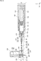
Fig. 3 is a sectional view of a medicinal solution administering device and an administering instrument according to the first embodiment. -
Fig. 4 is an enlarged side view of a puncture part of an administering instrument according to the first embodiment. -
Fig. 5 is an enlarged plan view of a puncture part of an administering instrument according to the first embodiment. -
Fig. 6 is an enlarged side view of a puncture part of an administering instrument according to a second embodiment of the present invention. -
Fig. 7 is an enlarged plan view of a puncture part of an administering instrument according to the second embodiment. - Hereinafter, embodiments of the present invention are described with reference to the accompanying drawings. The following description does not limit the technical scope described in the claims and the meaning of terms used in the claims. Further, the dimensional ratios in the drawings are exaggerated for convenience of description, and may differ from the actual ratios.
-
Figs. 1 to 5 are diagrams for explaining a medicinalsolution administering system 10, a medicinalsolution administering device 100, and an administeringinstrument 200 according to the first embodiment. In the diagrams, an arrow X indicates a "longitudinal direction (extending direction of a tube 240)" of the medicinalsolution administering device 100 and the administeringinstrument 200, an arrow Y indicates a "width direction (depth direction)" of the medicinalsolution administering device 100 and the administeringinstrument 200, and an arrow Z indicates a "height direction (thickness direction of a puncture part 230)" of the medicinalsolution administering device 100 and the administeringinstrument 200. Further, a sectional view illustrated inFig. 3 is a longitudinal sectional view (sectional view taken along the section X-Z) of the medicinalsolution administering device 100 and the administeringinstrument 200. - The medicinal
solution administering system 10 is used to administer a medicinal solution to a living body. As illustrated inFig. 1 , the medicinalsolution administering system 10 includes the medicinalsolution administering device 100 and the administeringinstrument 200. - As illustrated in
Figs. 2 and3 , when the medicinalsolution administering system 10 is used to administer a medicinal solution, the medicinalsolution administering device 100 and thepuncture part 230 of the administeringinstrument 200 are attached to a body surface H of a user. The location of the body of the user to which the medicinalsolution administering device 100 and thepuncture part 230 are attached is not particularly limited, but is the abdomen or thigh for example. - The medicinal
solution administering system 10 can continuously administer, for example, a medicinal solution (not shown) filled in amedicinal solution container 110 of the medicinalsolution administering device 100 to a living body over a relatively long time (for example, a few minutes to a few hours) by a pressing action of aplunger 130. The medicinalsolution administering system 10 may intermittently administer the medicinal solution to the living body. - As illustrated in
Fig. 3 , the medicinalsolution administering device 100 includes themedicinal solution container 110 in which a medicinal solution is filled, ahousing 120 for holding the medicinal solution container therein, and theplunger 130 for pushing out the medicinal solution held in themedicinal solution container 110 to thetube 240 described later. - The
medicinal solution container 110 has a cylindrical body including alumen 111 in which the medicinal solution is filled. A tip of theplunger 130 is inserted into themedicinal solution container 110. Agasket 131 is disposed at the tip of theplunger 130. Thegasket 131 can be made of, for example, a rubber material or a resin material such as an elastomer. The outer peripheral portion of thegasket 131 liquid-tightly contacts the inner peripheral surface of themedicinal solution container 110, which liquid-tightly seals a proximal end side of thegasket 131. - The
medicinal solution container 110 is constituted by a so-called pre-filled type medicinal solution container. The medicinal solution is therefore filled, in advance, in thelumen 111 of themedicinal solution container 110. Examples of the medicinal solution include a protein preparation, a narcotic analgesic, and a diuretic. - A sealing
member 113 for preventing leakage of the medicinal solution is provided in a tip opening (discharge port) of themedicinal solution container 110. The tip opening of themedicinal solution container 110 is disposed so as to project to the outside of thehousing 120. - The
plunger 130 is configured to be movable forward with respect to themedicinal solution container 110 toward the tip side (left side inFig. 3 ) of themedicinal solution container 110 by an advancing mechanism (not shown). Theplunger 130 moves forward with respect to themedicinal solution container 110 to push out the medicinal solution to thetube 240 from thelumen 111 of themedicinal solution container 110. - The
housing 120 accommodates therein a battery for supplying power necessary for each operation of the medicinalsolution administering device 100, a substrate to which a controller unit for controlling a motor is attached, a drive mechanism for driving the advancing mechanism, and so on (all are not shown). - The medicinal
solution administering device 100 is configured as a patch type device attached to the body surface (skin) H of the user and used. Thehousing 120 of the medicinalsolution administering device 100 has, on a contact surface (bottom surface) 121, a sheet-like adhesive part (not shown) that can be adhered to the body surface. In the initial state before the medicinalsolution administering device 100 is attached to the user, a peelable protective sheet is attached to an adhesive surface of the adhesive part. - As illustrated in
Figs. 1 and 2 , the administeringinstrument 200 is configured to be connectable to the medicinalsolution administering device 100. - As outlined with reference to
Figs. 3 to 5 , the administeringinstrument 200 includes aconnector 210, aneedle tube 220 to puncture a living body, the puncture part (cannula housing) 230, thetube 240, and a punctureauxiliary tool 250 for assisting theneedle tube 220 in puncturing the living body. - As illustrated in
Fig. 3 , theconnector 210 has acommunication part 211 that can communicate with thelumen 111 of themedicinal solution container 110. Theconnector 210 is configured to be connectable to the medicinalsolution administering device 100 via a mountingpart 215 fixed to theconnector 210. As illustrated inFig. 3 , the mountingpart 215 is externally fitted around the tip of themedicinal solution container 110 projecting to the outside of thehousing 120, so that the mountingpart 215 can be connected to the medicinalsolution administering device 100. - As illustrated in
Fig. 3 , thecommunication part 211 of theconnector 210 includes afirst connection part 213 connected to asecond end part 242 of thetube 240 and a second connection part 214 communicating with thelumen 111 of themedicinal solution container 110. - The
first connection part 213 of thecommunication part 211 is constituted by an insertion hole into which thesecond end part 242 of thetube 240 is inserted and fixed. The second connection part 214 of thecommunication part 211 is constituted by aconnection needle tube 212 having a needle tip capable of puncturing the sealingmember 113. An end on theconnector 210 side of theconnection needle tube 212 is fixed to theconnector 210. - The
tube 240 and thelumen 111 of themedicinal solution container 110 communicate with each other in a state (state illustrated inFig. 3 ) where theconnector 210 is connected to the medicinalsolution administering device 100 through the mountingpart 215 and where the needle tip of theconnection needle tube 212 penetrates the sealingmember 113 of the medicinalsolution administering device 100. - As illustrated in
Fig. 3 , thepuncture part 230 includes acontact surface 231 that is a lower end of thepuncture part 230 and comes into contact with the body surface H of the user, aneedle holding part 232 that is disposed above thecontact surface 231 and holds theneedle tube 220 so that a tip (lower end) 221 of theneedle tube 220 projects from thecontact surface 231, acommunication passage 233 that communicates with a lumen of theneedle tube 220, and a fixingpart 234 that is disposed above thecontact surface 231 and fixes afirst end part 241 of thetube 240 to thepuncture part 230. - The
tube 240 is configured so that a medicinal solution can be supplied from thelumen 111 of themedicinal solution container 110 to theneedle tube 220 via thecommunication part 211 of theconnector 210 and thecommunication passage 233 of thepuncture part 230. As illustrated inFigs. 3 and5 , thetube 240 includes thefirst end part 241 connected to thepuncture part 230, thesecond end part 242 connected to theconnector 210, and atube body 243 extending from thefirst end part 241 to thesecond end part 242. - The "
first end part 241" and the "second end part 242" in the present embodiment do not specify the exact positions of thetube 240, but mean a certain range of a part of thetube 240 fixed to (inserted into) thepuncture part 230 and a certain range of a part of thetube 240 fixed to (inserted into) theconnector 210. Further, the "tube body 243" in the present embodiment means a part of thetube 240 exposed from thepuncture part 230 and theconnector 210 in the plan view illustrated inFig. 5 . - As illustrated in
Fig. 5 , thetube body 243 has a total length longer than a straight-line distance d1 between thefirst end part 241 and the second end part 242 (length of thetube body 243 straightened out). Further, at least a part of thetube body 243 extends in a bellows shape. - The "bellows shape" means, in the plan view illustrated in
Fig. 5 , a two-dimensionally curved or bent shape in the Y-direction ofFig. 5 with respect to a straight line T1 connecting a boundary b1 between thefirst end part 241 and the tube body 243 (an end on thefirst end part 241 side of the tube body 243) and a boundary b2 between thesecond end part 242 and the tube body 243 (an end on thesecond end part 242 side of the tube body 243). In other words, thetube 240 has a shape in which at least a part of thetube body 243 is bent in the Y-direction. - The length, in the Y-direction, of the curved or bent part (bellows part) of the
tube body 243, the number of repetitions of curvature or bending in the direction in which thetube body 243 extends, the position at which the bellows part of thetube body 243 is formed, and so on are not particularly limited, and can be modified suitably. - The length of the
tube body 243 means a length of the entirety of thetube 240 stretched to a nearly straight shape (the maximum length of the tube body 243). Further, the straight-line distance d1 between thefirst end part 241 and thesecond end part 242 corresponds to a length of the straight line connecting the boundary b1 and the boundary b2. - The
tube 240 can be formed to have a total length (length in a state where thefirst end part 241, thesecond end part 242, and thetube body 243 are straightened out) of, for example, 20 mm to 200 mm, thefirst end part 241 of the tube 240 (length of a part inserted into the puncture part 230) can be formed to be, for example, 2 mm to 20 mm, thesecond end part 242 of the tube 240 (length of a part inserted into the connector 210) can be formed to be, for example, 2 mm to 20 mm, and thetube body 243 of thetube 240 can be formed to have a total length (length in a state where thetube body 243 is straightened out) of, for example, 15 mm to 196 mm. Further, a part with a bellows shape of thetube body 243 can be formed to have a length of, for example, 15 mm to 196 mm in a state where the part is straightened out. - The straight-line distance d1 between the
first end part 241 and thesecond end part 242 can be 10 mm to 150 mm, for example. The total length of thetube body 243 is preferably 1.3 to 10 times longer than the straight-line distance d1. - The
tube 240 can be made of, for example, a hollow member made of resin having flexibility. Specific examples of the constituent material of thetube 240 include polyethylene, polypropylene, polybutadiene, polyolefin such as ethylene-propylene copolymer and ethylene-vinyl acetate copolymer, thermoplastic resin such as flexible polyvinyl chloride, various rubbers such as silicone rubber and latex rubber, and various elastomers such as polyurethane elastomer, polyamide elastomer, and polyester elastomer. - As illustrated in
Fig. 3 , in order to supply the medicinal solution to the user, the punctureauxiliary tool 250 is attached to thepuncture part 230. The punctureauxiliary tool 250 holds an introducer needle (inner needle) 251. Theintroducer needle 251 is inserted into thecommunication passage 233 of thepuncture part 230 and the lumen of theneedle tube 220 in a state where the punctureauxiliary tool 250 is attached to thepuncture part 230. In this state, a tip of theintroducer needle 251 projects from the tip of theneedle tube 220. The user can insert theneedle tube 220 into the living body by puncturing the living body with theneedle tube 220 with theintroducer needle 251 inserted into theneedle tube 220 while preventing theneedle tube 220 from being broken. - The puncture
auxiliary tool 250 is detached from thepuncture part 230 after theneedle tube 220 punctures the living body. Theintroducer needle 251 is removed from the lumen of theneedle tube 220 when the punctureauxiliary tool 250 is detached from thepuncture part 230. As illustrated inFig. 3 , the tip of theneedle tube 220 is formed to be a pointed end so that the tip can be inserted into the living body, and theneedle tube 220 is formed to have a taper shape toward a proximal end in the vicinity thereof so that the medicinal solution flows efficiently from thecommunication passage 233 to the lumen of theneedle tube 220. - When the
introducer needle 251 is removed, in theneedle tube 220, the lumen of theneedle tube 220 communicates with thecommunication passage 233 of thepuncture part 230. Further, the lumen of theneedle tube 220 communicates with the lumen of thetube 240 via thecommunication passage 233. The administeringinstrument 200 administers, to the living body, the medicinal solution fed from themedicinal solution container 110 of the medicinalsolution administering device 100 via thetube 240 with theneedle tube 220 puncturing the living body. In the vicinity of the proximal end (near the upper end) of thecommunication passage 233, a sealingmember 236 is disposed to prevent the leakage of the medicinal solution from the proximal end of thecommunication passage 233. - The
introducer needle 251 can be constituted by a metal needle, for example. Further, theneedle tube 220 can be constituted by, for example, a tubular member (cannula) made of resin. - The puncture
auxiliary tool 250 can be prepared in a state of being attached in advance to thepuncture part 230, for example, before the use of the medicinalsolution administering system 10. In the present embodiment, theneedle tube 220 is constituted as a double needle that punctures the living body with theintroducer needle 251 inserted. For example, instead of such a double needle structure, theneedle tube 220 may have a structure that enables the living body to be punctured only with theneedle tube 220. In the case of such a structure, theneedle tube 220 is preferably configured by a metal needle. - As illustrated in
Fig. 3 , thecommunication passage 233 of thepuncture part 230 includes afirst channel 233a extending from the proximal end of theneedle tube 220 along an axis of theneedle tube 220 and asecond channel 233b communicating thefirst channel 233a and thefirst end part 241 of thetube 240 with each other. - As illustrated in
Fig. 3 , the fixingpart 234 of thepuncture part 230 is constituted by an insertion hole communicating with thesecond channel 233b. Thefirst end part 241 of thetube 240 is inserted into the fixingpart 234 and fitted thereinto, and thereby is fixed with respect to thepuncture part 230. - As illustrated in
Fig. 3 , the projecting direction of theneedle tube 220 from thecontact surface 231 is substantially perpendicular to thecontact surface 231. Thus, the axis of theneedle tube 220 intersects thecontact surface 231 substantially perpendicularly. - As illustrated in
Fig. 3 , thepuncture part 230 of the administeringinstrument 200 has a thickness (dimension in the horizontal direction illustrated inFig. 3 ) t1 smaller than a thickness t2 of thehousing 120 of the medicinalsolution administering device 100. It should be noted that, in a state where thepuncture part 230 is placed on a horizontal plane, a thickness t1 of thepuncture part 230 is a dimension of a portion having the largest thickness of thepuncture part 230. Similarly, in a state where thehousing 120 is placed on a horizontal plane, the thickness t2 of thehousing 120 is a dimension of a portion having the largest thickness of thehousing 120. - The
puncture part 230 can be formed to have a thickness t1 of 3 mm to 30 mm, for example. Further, thehousing 120 can be formed to have a thickness t2 of 10 mm to 30 mm, for example. - As with the medicinal
solution administering device 100, the administeringinstrument 200 is configured as a patch type instrument adhered to the body surface H of the user and used. Thepuncture part 230 of the administeringinstrument 200 has, on a contact surface (bottom surface) 231, a sheet-like adhesive part (not shown) that can be adhered to the body surface. In the initial state before the administeringinstrument 200 is attached to the user, a peelable protective sheet is attached to an adhesive surface of the adhesive part. - In a case where the administering
instrument 200 punctures the living body with the punctureauxiliary tool 250 attached to thepuncture part 230 and the tip of theintroducer needle 251 projecting from the tip of theneedle tube 220, thecontact surface 231 of thepuncture part 230 is adhered to the body surface of the user. The punctureauxiliary tool 250 is detached after theneedle tube 220 punctures the living body, and thepuncture part 230 remains on the body surface H of the user in a state where theneedle tube 220 punctures the living body. In this state, theplunger 130 of the medicinalsolution administering device 100 moves forward in themedicinal solution container 110, which allows the medicinal solution filled in thelumen 111 of themedicinal solution container 110 of the medicinalsolution administering device 100 to be fed to the lumen of theneedle tube 220 via thecommunication part 211 of theconnector 210, thetube 240, and thecommunication passage 233 of thepuncture part 230. - As described above, the administering
instrument 200 according to the present embodiment includes theconnector 210 that includes thecommunication part 211 capable of communicating with thelumen 111 of themedicinal solution container 110 and is connectable to the medicinalsolution administering device 100, theneedle tube 220 that punctures the living body, thepuncture part 230 including thecontact surface 231 that is provided in a lower end to contact the body surface H of the living body, theneedle holding part 232 that is provided above thecontact surface 231 to hold theneedle tube 220 so that a tip of theneedle tube 220 projects from thecontact surface 231, and thecommunication passage 233 communicating with the lumen of theneedle tube 220; and thetube 240 that includes thefirst end part 241 connected to thepuncture part 230, thesecond end part 242 connected to theconnector 210, and thetube body 243 communicating from thefirst end part 241 to thesecond end part 242 and is configured to supply the medicinal solution from thelumen 111 of themedicinal solution container 110 to theneedle tube 220 via thecommunication part 211 of theconnector 210 and thecommunication passage 233 of thepuncture part 230. Thetube body 243 has a total length longer than the straight-line distance d1 between thefirst end part 241 and thesecond end part 242. - The administering
instrument 200 is sometimes disposed in such a manner that, for example, in a state where thepuncture part 230 and thehousing 120 are attached to the curved body surface H of the user and so on, the position of thecontact surface 121 of thehousing 120 is higher than the position of thecontact surface 231 of the puncture part 230 (the distance away from the body surface H is larger in the former than in the latter). Particularly, in a case where thepuncture part 230 is formed to have a thin shape in consideration of convenience at the use of the administering instrument 200 (such as avoiding the interference of the administeringinstrument 200 attached to the body surface H), the thickness t1 of thepuncture part 230 is smaller than the thickness t2 of thehousing 120; therefore, the deviation in the height direction between thecontact surface 231 of thepuncture part 230 and thecontact surface 121 of thehousing 120 is significant. When the user moves such as twisting his/her body, due to the deviation in the height direction at the time of attachment to the body surface H as described above, a force that lifts thepuncture part 230 from the medicinalsolution administering device 100 side toward thepuncture part 230 acts via thefirst end part 241 of thetube 240 fixed to thepuncture part 230. This may remove thepuncture part 230 from the body surface H and theneedle tube 220 held by thepuncture part 230 may come out of the living body. - In light of the foregoing issues, in the administering
instrument 200 according to the present embodiment, thetube body 243 has a total length longer than the straight-line distance d1 between thefirst end part 241 and thesecond end part 242. In a case where a force acting on thepuncture part 230 from the medicinalsolution administering device 100 side via the tube 240 (force that lifts the puncture part 230) is to develop, thetube 240 absorbs (reduces) the force by deforming a part of thetube body 243. This allows the administeringinstrument 200 to prevent the force from being conveyed to thepuncture part 230 via thetube 240. Therefore, the administeringinstrument 200 can suitably prevent theneedle tube 220 from coming out of the living body during administration of the medicinal solution. Particularly, even in a case where thetube 240 is made of a material inferior in flexibility to other resin materials such as polybutadiene, the administeringinstrument 200 can suitably prevent theneedle tube 220 from coming out of the living body during administration of the medicinal solution. - Further, in the administering
instrument 200, at least a part of thetube body 243 extends in a bellows shape. This enables thetube body 243 to absorb the force that lifts thepuncture part 230 at the part formed in the shape of a bellows. - Further, the medicinal
solution administering system 10 according to the present embodiment includes the administeringinstrument 200 and the medicinalsolution administering device 100 that has themedicinal solution container 110, thehousing 120 for holding themedicinal solution container 110 therein, theplunger 130 for pushing out the medicinal solution in themedicinal solution container 110 to thetube 240. With the use of the medicinalsolution administering system 10, it is possible to absorb the force acting on the puncture part 230 (force that lifts the puncture part 230) at thetube body 243 of thetube 240 during administration of the medicinal solution. Therefore, the medicinalsolution administering system 10 can suitably prevent theneedle tube 220 held by thepuncture part 230 from coming out of the living body. - Further, in the medicinal
solution administering system 10, the thickness t1 of thepuncture part 230 of the administeringinstrument 200 is smaller than the thickness t2 of thehousing 120 of the medicinalsolution administering device 100. According to the medicinalsolution administering system 10, it is therefore possible to reduce the thickness of thepuncture part 230 and suitably prevent the occurrence of a problem that theneedle tube 220 held in thepuncture part 230 comes out of the living body due to the reduction in thickness of thepuncture part 230. - The description goes on to an administering
instrument 200A according to the second embodiment. The same configurations as those in the first embodiment are denoted by the same reference numerals and description thereof is omitted. In addition, configurations not particularly mentioned in the second embodiment can be configured in substantially the same manner as described above in the first embodiment. -
Figs. 6 and 7 are diagrams illustrating the administeringinstrument 200A according to the second embodiment. - The administering
instrument 200 according to the first embodiment is so formed that at least a part of thetube body 243 of thetube 240 extends in a bellows shape (seeFig. 5 ). On the other hand, in the administeringinstrument 200A according to the second embodiment, at least a part of atube body 343 of atube 340 extends in a spiral shape as illustrated inFigs. 6 and 7 . - The
tube body 343 has a total length longer than a straight-line distance d1 between afirst end part 341 and asecond end part 342. - The "spiral" shape according to the present embodiment means a shape of the
tube 340 that winds three-dimensionally around an axis of thetube 240 straightened out. In other words, thetube 340 has a shape in which at least a part of thetube body 343 is bent in a spiral shape in the X-Y-Z direction. - The length of the spiral part of the
tube body 343, the number of repetitions of spiral in the direction in which thetube body 343 extends, the position at which the spiral part of thetube body 343 is formed, and so on are not particularly limited, and can be modified suitably. - The length of the
tube body 343 means a length of the entirety of thetube 340 stretched to a nearly straight shape (the maximum length of the tube body 343). Further, the straight-line distance d1 between thefirst end part 341 and thesecond end part 342 corresponds to, as illustrated inFig. 7 , a straight-line distance between a boundary b1 (an end on thefirst end part 341 side of the tube body 343) between thefirst end part 341 and thetube body 343 and a boundary b2 (an end on thesecond end part 342 side of the tube body 343) between thesecond end part 342 and thetube body 343. - The
tube 340 can be formed to have a total length (length in a state where thefirst end part 341, thesecond end part 342, and thetube body 343 are straightened out) of, for example, 20 mm to 200 mm, thefirst end part 341 of the tube 340 (length of a part inserted into the puncture part 230) can be formed to be, for example, 2 mm to 20 mm, thesecond end part 342 of the tube 340 (length of a part inserted into the connector 210) can be formed to be, for example, 2 mm to 20 mm, and thetube body 343 of thetube 340 can be formed to have a total length (length in a state where thetube body 243 is straightened out) of, for example, 15 mm to 196 mm. Further, a part with a spiral shape of thetube body 343 can be formed to have a length of, for example, 15 mm to 195 mm in a state where the part is straightened out. - The straight-line distance d1 between the
first end part 341 and thesecond end part 342 can be 10 mm to 150 mm, for example. The total length of thetube body 343 is preferably 1.3 to 10 times longer than the straight-line distance d1. - As described above, in the administering
instrument 200A according to the present embodiment, at least a part of thetube body 343 of thetube 340 extends in a spiral shape. Therefore, in the administeringinstrument 200A, as with the administeringinstrument 200 according to the first embodiment, in a case where a force acting on thepuncture part 230 from the medicinalsolution administering device 100 side via the tube 340 (force that lifts the puncture part 230) is to develop, a part of thetube body 343 deforms to absorb (reduce) the force. Thus, the administeringinstrument 200A can suitably prevent theneedle tube 220 from coming out of the living body during administration of the medicinal solution. - Further, since at least a part of the
tube body 343 of thetube 340 has a spiral shape, in a case where a force that lifts thepuncture part 230 is to develop, thetube body 343 deforms three-dimensionally to absorb the force, which further prevents thepuncture part 230 from being lifted. Further, since at least a part of thetube body 343 flexes to have a three-dimensional spiral shape, even in a case where thetube body 343 has an elongated part that absorbs the force, it is possible to prevent an excessive long distance between thefirst end part 341 and thesecond end part 342. Thus, the administeringinstrument 200A can be made more compact. - The administering instrument and the medicinal solution administering system according to the embodiments of the present invention are describe above. The present invention is not limited only to the configurations described above, and can be modified suitably on the basis of the description of claims.
- For example, the tube body may both have the bellows shape described in the first embodiment and the spiral shape described in the second embodiment. Further, the shape of the tube body is not particularly limited as long as the tube body has a total length longer than the straight-line distance between the first end part and the second end part to absorb (reduce) the force that lifts the puncture part. The tube body can be configured to have, for example, a shape other than the bellows or spiral shape.
- In addition, the material, shape, size, and arrangement of the members constituting the administering instrument and the medicinal solution administering system, and the connecting/coupling structures of the members thereof are not particularly limited as long as the effects of the present invention are exhibited, and can be arbitrarily changed and replaced. Moreover, it is also possible to appropriately add any constituent members or the like, which are not particularly described in the specification, to the administering instrument and the medicinal solution administering system.
- This application is on the basis of Japanese Patent Application No.
2018-067426 filed on March 30, 2018 -
- 10 Medicinal solution administering system
- 100 Medicinal solution administering device
- 110 Medicinal solution container
- 111 Lumen
- 120 Housing
- 121 Contact surface of housing
- 130 Plunger
- 200, 200A Administering instrument
- 210 Connector
- 211 Communication part
- 215 Mounting part
- 220 Needle tube
- 230 Puncture part
- 231 Contact surface of puncture part
- 232 Needle holding part
- 233 Communication passage
- 234 Fixing part
- 240, 340 Tube
- 241, 341 First end part
- 242, 342 Second end part
- 243, 343 Tube body
- 250 Puncture auxiliary tool
- d1 Straight-line distance between first end part and second end part
- t1 Thickness of puncture part
- t2 Thickness of housing
- H Body surface
Claims (6)
- An administering instrument connectable to a medicinal solution administering device including a medicinal solution container in which a medicinal solution is filled, the administering instrument comprising:a connector that includes a communication part capable of communicating with a lumen of the medicinal solution container and is connectable to the medicinal solution administering device;a needle tube that punctures a living body;a puncture part including a contact surface that is provided in a lower end to contact a living body surface of the living body, a needle holding part that is provided above the contact surface to hold the needle tube so that a tip of the needle tube projects from the contact surface, and a communication passage communicating with a lumen of the needle tube; anda tube that includes a first end part connected to the puncture part, a second end part connected to the connector, and a tube body communicating from the first end part to the second end part, and is configured to supply the medicinal solution from the lumen of the medicinal solution container to the needle tube via the communication part of the connector and the communication passage of the puncture part, whereinthe tube body has a total length longer than a straight-line distance between the first end part and the second end part.
- The administering instrument according to claim 1, wherein at least a part of the tube body extends in a bellows shape.
- The administering instrument according to claim 1 or 2, wherein at least a part of the tube body extends in a spiral shape.
- The administering instrument according to any one of claims 1 to 3, wherein the total length of the tube body is 1.3 to 10 times longer than the straight-line distance between the first end part and the second end part.
- A medicinal solution administering system comprising:the administering instrument according to any one of claims 1 to 4; andthe medicinal solution administering device including the medicinal solution container, a housing that holds the medicinal solution container, and a plunger that pushes out the medicinal solution in the medicinal solution container to the tube.
- The medicinal solution administering system according to claim 5, wherein the puncture part of the administering instrument has a thickness smaller than a thickness of the housing of the medicinal solution administering device.
Applications Claiming Priority (2)
| Application Number | Priority Date | Filing Date | Title |
|---|---|---|---|
| JP2018067426 | 2018-03-30 | ||
| PCT/JP2019/013309 WO2019189434A1 (en) | 2018-03-30 | 2019-03-27 | Medicating appliance and liquid medicine administering system |
Publications (2)
| Publication Number | Publication Date |
|---|---|
| EP3760251A4 EP3760251A4 (en) | 2021-01-06 |
| EP3760251A1 true EP3760251A1 (en) | 2021-01-06 |
Family
ID=68061979
Family Applications (1)
| Application Number | Title | Priority Date | Filing Date |
|---|---|---|---|
| EP19777665.1A Withdrawn EP3760251A1 (en) | 2018-03-30 | 2019-03-27 | Medicating appliance and liquid medicine administering system |
Country Status (4)
| Country | Link |
|---|---|
| US (1) | US20210008277A1 (en) |
| EP (1) | EP3760251A1 (en) |
| JP (1) | JPWO2019189434A1 (en) |
| WO (1) | WO2019189434A1 (en) |
Families Citing this family (3)
| Publication number | Priority date | Publication date | Assignee | Title |
|---|---|---|---|---|
| EP4501374A4 (en) * | 2022-06-17 | 2025-06-25 | Terumo Kabushiki Kaisha | Puncture device and medicinal solution administering device equipped with puncture device |
| WO2026053511A1 (en) * | 2024-09-09 | 2026-03-12 | テルモ株式会社 | Drug solution administration device |
| WO2026053512A1 (en) * | 2024-09-09 | 2026-03-12 | テルモ株式会社 | Drug solution administration device |
Family Cites Families (9)
| Publication number | Priority date | Publication date | Assignee | Title |
|---|---|---|---|---|
| EP1716884B1 (en) | 1998-10-29 | 2013-12-11 | Medtronic MiniMed, Inc. | Reservoir connector |
| US11357910B2 (en) * | 2007-12-31 | 2022-06-14 | Deka Products Limited Partnership | Pump assembly with switch |
| EP3653531B1 (en) * | 2009-01-21 | 2022-01-19 | Becton, Dickinson and Company | Infusion set |
| EP2484402A3 (en) * | 2011-02-08 | 2012-10-03 | Region Nordjylland, Aalborg Sygehus | A venflon component |
| US20120238849A1 (en) * | 2011-03-17 | 2012-09-20 | Medtronic Minimed, Inc. | Infusion set component with integrated analyte sensor conductors |
| US9333292B2 (en) * | 2012-06-26 | 2016-05-10 | Medtronic Minimed, Inc. | Mechanically actuated fluid infusion device |
| RU2015103182A (en) * | 2012-08-20 | 2016-10-10 | Ф.Хоффманн-Ля Рош Аг | THERAPEUTIC SYSTEM WITH ADAPTER FOR INFUSION KIT |
| US9265881B2 (en) * | 2013-10-14 | 2016-02-23 | Medtronic Minimed, Inc. | Therapeutic agent injection device |
| JP6518223B2 (en) | 2016-10-18 | 2019-05-22 | 株式会社ティー・ピー・エス | Electric wire with connection terminal and method of manufacturing the same |
-
2019
- 2019-03-27 EP EP19777665.1A patent/EP3760251A1/en not_active Withdrawn
- 2019-03-27 WO PCT/JP2019/013309 patent/WO2019189434A1/en not_active Ceased
- 2019-03-27 JP JP2020509231A patent/JPWO2019189434A1/en active Pending
-
2020
- 2020-09-30 US US17/038,681 patent/US20210008277A1/en not_active Abandoned
Also Published As
| Publication number | Publication date |
|---|---|
| WO2019189434A1 (en) | 2019-10-03 |
| US20210008277A1 (en) | 2021-01-14 |
| JPWO2019189434A1 (en) | 2021-03-25 |
| EP3760251A4 (en) | 2021-01-06 |
Similar Documents
| Publication | Publication Date | Title |
|---|---|---|
| US20210008277A1 (en) | Administering instrument and drug solution administering system | |
| CN113164678B (en) | Liquid medicine feeding device | |
| EP3219344A1 (en) | Drug-solution administration device | |
| WO2004054643A1 (en) | Needle body for medical use and liquid-introducing tool | |
| US20230211075A1 (en) | Patch injection device with release liner removal | |
| US20210008273A1 (en) | Drug solution administration device | |
| US11724025B2 (en) | Administering instrument and drug solution administering system | |
| CN113164676B (en) | Liquid medicine feeding device and bracket device | |
| JP2022136595A (en) | Drug solution administration device | |
| EP3744367A1 (en) | Needle infusion set for insulin infusion | |
| CN116457039A (en) | Liquid medicine feeding device | |
| WO2023188851A1 (en) | Drug solution administration device | |
| US20260083905A1 (en) | Medical device | |
| WO2020195352A1 (en) | Dosing instrument and drug solution dosing system | |
| CN220070341U (en) | Insulin pump injection assembly convenient to injection location | |
| WO2021157556A1 (en) | Medicine administering device | |
| CN219127706U (en) | Infusion device | |
| WO2021157654A1 (en) | Medicine administering device | |
| US20250018164A1 (en) | Liquid medicine administration device | |
| US20250018154A1 (en) | Liquid medicine administration device | |
| JP2019176938A (en) | Medical fluid dispenser | |
| JP2008161239A (en) | Drug application tube | |
| US20210001050A1 (en) | Syringe assembly and prefilled syringe | |
| WO2024171479A1 (en) | Drug solution administering device and medical apparatus package | |
| JP2024044241A (en) | Medical puncture needles and needle protection members |
Legal Events
| Date | Code | Title | Description |
|---|---|---|---|
| STAA | Information on the status of an ep patent application or granted ep patent |
Free format text: STATUS: THE INTERNATIONAL PUBLICATION HAS BEEN MADE |
|
| PUAI | Public reference made under article 153(3) epc to a published international application that has entered the european phase |
Free format text: ORIGINAL CODE: 0009012 |
|
| STAA | Information on the status of an ep patent application or granted ep patent |
Free format text: STATUS: REQUEST FOR EXAMINATION WAS MADE |
|
| 17P | Request for examination filed |
Effective date: 20201001 |
|
| A4 | Supplementary search report drawn up and despatched |
Effective date: 20201106 |
|
| AK | Designated contracting states |
Kind code of ref document: A1 Designated state(s): AL AT BE BG CH CY CZ DE DK EE ES FI FR GB GR HR HU IE IS IT LI LT LU LV MC MK MT NL NO PL PT RO RS SE SI SK SM TR |
|
| AX | Request for extension of the european patent |
Extension state: BA ME |
|
| DAV | Request for validation of the european patent (deleted) | ||
| DAX | Request for extension of the european patent (deleted) | ||
| STAA | Information on the status of an ep patent application or granted ep patent |
Free format text: STATUS: EXAMINATION IS IN PROGRESS |
|
| 17Q | First examination report despatched |
Effective date: 20240318 |
|
| STAA | Information on the status of an ep patent application or granted ep patent |
Free format text: STATUS: THE APPLICATION IS DEEMED TO BE WITHDRAWN |
|
| 18D | Application deemed to be withdrawn |
Effective date: 20240719 |