EP3712923A1 - Ion source for inductively coupled plasma mass spectrometry - Google Patents
Ion source for inductively coupled plasma mass spectrometry Download PDFInfo
- Publication number
- EP3712923A1 EP3712923A1 EP19163530.9A EP19163530A EP3712923A1 EP 3712923 A1 EP3712923 A1 EP 3712923A1 EP 19163530 A EP19163530 A EP 19163530A EP 3712923 A1 EP3712923 A1 EP 3712923A1
- Authority
- EP
- European Patent Office
- Prior art keywords
- sample
- icp source
- plasma
- downwards
- icp
- Prior art date
- Legal status (The legal status is an assumption and is not a legal conclusion. Google has not performed a legal analysis and makes no representation as to the accuracy of the status listed.)
- Withdrawn
Links
- 238000001095 inductively coupled plasma mass spectrometry Methods 0.000 title claims description 36
- 238000009616 inductively coupled plasma Methods 0.000 claims abstract description 111
- 150000002500 ions Chemical class 0.000 claims abstract description 39
- 239000002245 particle Substances 0.000 claims abstract description 18
- 230000005484 gravity Effects 0.000 claims abstract description 10
- 238000001816 cooling Methods 0.000 claims description 32
- 230000006698 induction Effects 0.000 claims description 23
- 238000012387 aerosolization Methods 0.000 claims description 22
- 238000000608 laser ablation Methods 0.000 claims description 22
- 238000004949 mass spectrometry Methods 0.000 claims description 20
- 239000006199 nebulizer Substances 0.000 claims description 18
- 239000007921 spray Substances 0.000 claims description 17
- 230000008878 coupling Effects 0.000 claims description 15
- 238000010168 coupling process Methods 0.000 claims description 15
- 238000005859 coupling reaction Methods 0.000 claims description 15
- 238000000684 flow cytometry Methods 0.000 claims description 15
- 238000000034 method Methods 0.000 claims description 14
- XLYOFNOQVPJJNP-UHFFFAOYSA-N water Substances O XLYOFNOQVPJJNP-UHFFFAOYSA-N 0.000 claims description 6
- 230000001939 inductive effect Effects 0.000 claims description 5
- 238000001228 spectrum Methods 0.000 claims description 2
- 239000000523 sample Substances 0.000 description 88
- 210000004027 cell Anatomy 0.000 description 52
- 239000002184 metal Substances 0.000 description 17
- 229910052751 metal Inorganic materials 0.000 description 17
- 239000007789 gas Substances 0.000 description 14
- 239000012159 carrier gas Substances 0.000 description 12
- IJGRMHOSHXDMSA-UHFFFAOYSA-N Atomic nitrogen Chemical compound N#N IJGRMHOSHXDMSA-UHFFFAOYSA-N 0.000 description 9
- 238000000605 extraction Methods 0.000 description 9
- XKRFYHLGVUSROY-UHFFFAOYSA-N Argon Chemical compound [Ar] XKRFYHLGVUSROY-UHFFFAOYSA-N 0.000 description 8
- 239000000443 aerosol Substances 0.000 description 8
- 239000012491 analyte Substances 0.000 description 5
- 238000002347 injection Methods 0.000 description 5
- 239000007924 injection Substances 0.000 description 5
- 239000007788 liquid Substances 0.000 description 5
- 230000003287 optical effect Effects 0.000 description 5
- 239000000725 suspension Substances 0.000 description 5
- 241000699802 Cricetulus griseus Species 0.000 description 4
- 229910052786 argon Inorganic materials 0.000 description 4
- 238000004807 desolvation Methods 0.000 description 4
- 238000001514 detection method Methods 0.000 description 4
- 239000002105 nanoparticle Substances 0.000 description 4
- 229910052757 nitrogen Inorganic materials 0.000 description 4
- 210000001672 ovary Anatomy 0.000 description 4
- 238000012546 transfer Methods 0.000 description 4
- 238000004458 analytical method Methods 0.000 description 3
- 239000003990 capacitor Substances 0.000 description 3
- 238000009826 distribution Methods 0.000 description 3
- 230000005672 electromagnetic field Effects 0.000 description 3
- 238000002354 inductively-coupled plasma atomic emission spectroscopy Methods 0.000 description 3
- 238000003913 materials processing Methods 0.000 description 3
- 239000007787 solid Substances 0.000 description 3
- RYGMFSIKBFXOCR-UHFFFAOYSA-N Copper Chemical compound [Cu] RYGMFSIKBFXOCR-UHFFFAOYSA-N 0.000 description 2
- BQCADISMDOOEFD-UHFFFAOYSA-N Silver Chemical compound [Ag] BQCADISMDOOEFD-UHFFFAOYSA-N 0.000 description 2
- 229910000831 Steel Inorganic materials 0.000 description 2
- 238000001636 atomic emission spectroscopy Methods 0.000 description 2
- 238000005452 bending Methods 0.000 description 2
- 238000011088 calibration curve Methods 0.000 description 2
- 239000006285 cell suspension Substances 0.000 description 2
- 238000012512 characterization method Methods 0.000 description 2
- 239000004020 conductor Substances 0.000 description 2
- 229910052802 copper Inorganic materials 0.000 description 2
- 239000010949 copper Substances 0.000 description 2
- 230000002596 correlated effect Effects 0.000 description 2
- 238000010586 diagram Methods 0.000 description 2
- LOKCTEFSRHRXRJ-UHFFFAOYSA-I dipotassium trisodium dihydrogen phosphate hydrogen phosphate dichloride Chemical compound P(=O)(O)(O)[O-].[K+].P(=O)(O)([O-])[O-].[Na+].[Na+].[Cl-].[K+].[Cl-].[Na+] LOKCTEFSRHRXRJ-UHFFFAOYSA-I 0.000 description 2
- 238000010494 dissociation reaction Methods 0.000 description 2
- 230000005593 dissociations Effects 0.000 description 2
- 230000000694 effects Effects 0.000 description 2
- PCHJSUWPFVWCPO-UHFFFAOYSA-N gold Chemical compound [Au] PCHJSUWPFVWCPO-UHFFFAOYSA-N 0.000 description 2
- 229910052737 gold Inorganic materials 0.000 description 2
- 239000010931 gold Substances 0.000 description 2
- 230000003760 hair shine Effects 0.000 description 2
- 238000005259 measurement Methods 0.000 description 2
- 239000000203 mixture Substances 0.000 description 2
- 239000002953 phosphate buffered saline Substances 0.000 description 2
- 230000010287 polarization Effects 0.000 description 2
- 239000004810 polytetrafluoroethylene Substances 0.000 description 2
- 229920001343 polytetrafluoroethylene Polymers 0.000 description 2
- 229910052709 silver Inorganic materials 0.000 description 2
- 239000004332 silver Substances 0.000 description 2
- 239000000243 solution Substances 0.000 description 2
- 239000002904 solvent Substances 0.000 description 2
- 239000010959 steel Substances 0.000 description 2
- 230000002459 sustained effect Effects 0.000 description 2
- 238000009834 vaporization Methods 0.000 description 2
- 230000008016 vaporization Effects 0.000 description 2
- 238000009423 ventilation Methods 0.000 description 2
- 238000002679 ablation Methods 0.000 description 1
- 230000001133 acceleration Effects 0.000 description 1
- CFQGDIWRTHFZMQ-UHFFFAOYSA-N argon helium Chemical compound [He].[Ar] CFQGDIWRTHFZMQ-UHFFFAOYSA-N 0.000 description 1
- 238000000559 atomic spectroscopy Methods 0.000 description 1
- 230000001413 cellular effect Effects 0.000 description 1
- 239000000919 ceramic Substances 0.000 description 1
- 238000000576 coating method Methods 0.000 description 1
- 230000000875 corresponding effect Effects 0.000 description 1
- 230000001419 dependent effect Effects 0.000 description 1
- 238000013461 design Methods 0.000 description 1
- 229910001873 dinitrogen Inorganic materials 0.000 description 1
- 230000005684 electric field Effects 0.000 description 1
- 238000000921 elemental analysis Methods 0.000 description 1
- 210000003527 eukaryotic cell Anatomy 0.000 description 1
- 239000012530 fluid Substances 0.000 description 1
- 239000001307 helium Substances 0.000 description 1
- 229910052734 helium Inorganic materials 0.000 description 1
- SWQJXJOGLNCZEY-UHFFFAOYSA-N helium atom Chemical compound [He] SWQJXJOGLNCZEY-UHFFFAOYSA-N 0.000 description 1
- 238000005286 illumination Methods 0.000 description 1
- 230000002452 interceptive effect Effects 0.000 description 1
- 238000005040 ion trap Methods 0.000 description 1
- 238000004519 manufacturing process Methods 0.000 description 1
- 239000000463 material Substances 0.000 description 1
- 239000012528 membrane Substances 0.000 description 1
- 238000012986 modification Methods 0.000 description 1
- 230000004048 modification Effects 0.000 description 1
- 238000012544 monitoring process Methods 0.000 description 1
- 238000002663 nebulization Methods 0.000 description 1
- 229910052756 noble gas Inorganic materials 0.000 description 1
- 238000005457 optimization Methods 0.000 description 1
- 238000000918 plasma mass spectrometry Methods 0.000 description 1
- 239000000843 powder Substances 0.000 description 1
- 238000011002 quantification Methods 0.000 description 1
- 230000035939 shock Effects 0.000 description 1
- 239000002002 slurry Substances 0.000 description 1
- 238000000935 solvent evaporation Methods 0.000 description 1
- 238000004611 spectroscopical analysis Methods 0.000 description 1
- 229910001220 stainless steel Inorganic materials 0.000 description 1
- 239000010935 stainless steel Substances 0.000 description 1
Images



Classifications
-
- H—ELECTRICITY
- H01—ELECTRIC ELEMENTS
- H01J—ELECTRIC DISCHARGE TUBES OR DISCHARGE LAMPS
- H01J49/00—Particle spectrometers or separator tubes
- H01J49/02—Details
- H01J49/10—Ion sources; Ion guns
- H01J49/105—Ion sources; Ion guns using high-frequency excitation, e.g. microwave excitation, Inductively Coupled Plasma [ICP]
-
- G—PHYSICS
- G01—MEASURING; TESTING
- G01N—INVESTIGATING OR ANALYSING MATERIALS BY DETERMINING THEIR CHEMICAL OR PHYSICAL PROPERTIES
- G01N15/00—Investigating characteristics of particles; Investigating permeability, pore-volume or surface-area of porous materials
- G01N15/10—Investigating individual particles
- G01N15/14—Optical investigation techniques, e.g. flow cytometry
-
- H—ELECTRICITY
- H01—ELECTRIC ELEMENTS
- H01J—ELECTRIC DISCHARGE TUBES OR DISCHARGE LAMPS
- H01J49/00—Particle spectrometers or separator tubes
- H01J49/0027—Methods for using particle spectrometers
- H01J49/0031—Step by step routines describing the use of the apparatus
-
- H—ELECTRICITY
- H01—ELECTRIC ELEMENTS
- H01J—ELECTRIC DISCHARGE TUBES OR DISCHARGE LAMPS
- H01J49/00—Particle spectrometers or separator tubes
- H01J49/02—Details
- H01J49/04—Arrangements for introducing or extracting samples to be analysed, e.g. vacuum locks; Arrangements for external adjustment of electron- or ion-optical components
-
- H—ELECTRICITY
- H01—ELECTRIC ELEMENTS
- H01J—ELECTRIC DISCHARGE TUBES OR DISCHARGE LAMPS
- H01J49/00—Particle spectrometers or separator tubes
- H01J49/02—Details
- H01J49/04—Arrangements for introducing or extracting samples to be analysed, e.g. vacuum locks; Arrangements for external adjustment of electron- or ion-optical components
- H01J49/0431—Arrangements for introducing or extracting samples to be analysed, e.g. vacuum locks; Arrangements for external adjustment of electron- or ion-optical components for liquid samples
- H01J49/0445—Arrangements for introducing or extracting samples to be analysed, e.g. vacuum locks; Arrangements for external adjustment of electron- or ion-optical components for liquid samples with means for introducing as a spray, a jet or an aerosol
- H01J49/045—Arrangements for introducing or extracting samples to be analysed, e.g. vacuum locks; Arrangements for external adjustment of electron- or ion-optical components for liquid samples with means for introducing as a spray, a jet or an aerosol with means for using a nebulising gas, i.e. pneumatically assisted
-
- G—PHYSICS
- G01—MEASURING; TESTING
- G01N—INVESTIGATING OR ANALYSING MATERIALS BY DETERMINING THEIR CHEMICAL OR PHYSICAL PROPERTIES
- G01N15/00—Investigating characteristics of particles; Investigating permeability, pore-volume or surface-area of porous materials
- G01N15/10—Investigating individual particles
- G01N15/14—Optical investigation techniques, e.g. flow cytometry
- G01N15/149—Optical investigation techniques, e.g. flow cytometry specially adapted for sorting particles, e.g. by their size or optical properties
-
- G—PHYSICS
- G01—MEASURING; TESTING
- G01N—INVESTIGATING OR ANALYSING MATERIALS BY DETERMINING THEIR CHEMICAL OR PHYSICAL PROPERTIES
- G01N15/00—Investigating characteristics of particles; Investigating permeability, pore-volume or surface-area of porous materials
- G01N15/10—Investigating individual particles
- G01N2015/1006—Investigating individual particles for cytology
Definitions
- the present invention relates to an inductively coupled plasma (ICP) ion source configured to be coupled to a mass spectrometer.
- the invention further relates to an ionization system comprising the ICP source, to an ICP-mass spectrometry system, and to a corresponding method of ICP mass spectrometry.
- ICP inductively coupled plasma
- ICP-MS Inductively coupled plasma mass spectrometry
- An ICP source usually comprises a plasma torch to confine the plasma discharge by means of a directed gas flow and to carry a sample aerosol into the center of the plasma discharge for dissociation and ionization.
- the sample aerosol is usually transported to the plasma discharge through a central injector tube of the torch.
- the torch axis is oriented horizontally, and the sample aerosol accordingly is transported to the plasma discharge using a carrier gas that flows horizontally through a horizontal injector tube.
- the carrier gas flow must be carefully adjusted to optimize sample transport to the plasma discharge and to ensure that the sample reaches a position within the plasma from which it can be extracted into the mass spectrometer system at highest possible ion yield.
- prior-art sample introduction systems for liquid samples and suspensions typically comprise a pneumatic nebulizer, which creates a broad droplet size distribution, often followed by a spray chamber for removing larger droplets, e.g., droplets having more than 10 ⁇ m diameter, from the aerosol (see, e.g., J. Olesik and L.
- sample introduction systems using a monodisperse microdroplet generator were disclosed in the following documents: S. Gschwind et al., "Capabilities of inductively coupled plasma mass spectrometry for the detection of nanoparticles carried by monodisperse microdroplets", J. Anal. At. Spectrom., 2011, 26, 1166-1174, DOI: 0.1039/C0JA00249F ; S. Gschwind et al., “Mass quantification of nanoparticles by single droplet calibration using inductively coupled plasma mass spectrometry", Anal. Chem. 2013, 85, 5875-5883, DOI: 10.1021/ac400608c ; K.
- P. Verboket et al. "A New Microfluidics-Based Droplet Dispenser for ICPMS", Analytical Chemistry 2014, 86, p. 6012, DOI: 10.1021/ac501149a discloses a microfluidic dispenser for introducing microdroplets into an ICP-MS.
- the chip is coupled with a cyclonic adapter, a heated steel tube, a membrane desolvator and an ICP-MS unit. Although the droplets fall vertically through the steel tube, the ICP-MS unit is oriented horizontally in the usual manner, and the droplets are introduced into the ICP-MS unit along a horizontal direction.
- WO 2008/080224 A1 discloses a flow cytometer that is coupled to an ICP-MS system.
- the plasma torch of the ICP source is oriented horizontally in the usual manner.
- ICP-OES inductively coupled plasma optical emission spectroscopy
- an upwardly pointing plasma torch is disclosed in A. Murtazin, S. Groh, and K. Niemax, "Measurement of element mass distributions in particle ensembles applying ICP-OES", J. Anal. At. Spectrom. 2010, 25, 1395-1401, DOI: 10.1039/c004946h .
- the plasma torch is employed for optical emission spectroscopy only and is incompatible with a mass spectrometer.
- US 4,766,287 , US 2015/255262 A1 and US 2016/0270201 A1 also disclose upwardly pointing plasma torches with a focus on applications in optical emission spectroscopy.
- WO 97/13141 discloses a microwave plasma monitoring system wherein a plasma flame is generated by microwaves in a waveguide, and optical emission from the flame is investigated by a spectrometer.
- the plasma flame is oriented vertically in a downward direction.
- Different types of samples such as droplets or particles are introduced using a suction pump that regulates the gas flow.
- the plasma source is not an ICP source, and the system is designed for optical spectroscopy only and is not compatible with a mass spectrometer.
- US 2014/0287162 discloses a downwardly oriented microwave plasma source for materials processing, e.g., for applying surface coatings or for powder production. Downwardly oriented plasma sources for materials processing are also disclosed in US 2005/0211018 A1 , US 2014/0217630 A1 , US 2013/0270261 A1 and US 2013/0118304 A1 . These setups are designed for industrial applications in materials processing and are clearly unsuitable for elemental analysis of samples. All the less are these setups suitable to be coupled to a mass spectrometer.
- the invention provides an ICP source for generating ions from a sample using an inductively coupled plasma.
- the ICP source is configured to be coupled to a mass spectrometer.
- the ICP source is configured to allow introduction of the sample into the plasma along a downwards-pointing vertical direction.
- Sample introduction into the plasma therefore takes place from the top.
- the sample is introduced into the plasma along the direction of the gravity vector.
- sample introduction is less sensitive to the carrier gas flow rate. It is even conceivable to introduce the sample without using any carrier gas flow at all, the sample trajectories before the entry of the sample into the plasma being determined exclusively by gravity. Thereby significant amounts of carrier gas can be saved, which is of some significance especially when the carrier gas is an expensive noble gas like argon or an argon-helium mixture.
- the size of droplets or objects (e.g. cells) that can reach the plasma is essentially only limited by the dimensions of the sample introduction system. Because impact of droplets or objects with the walls of the sample introduction system can be avoided, the proposed arrangement can reach up to 100% transport efficiency.
- Samples of any type and in any condition can be investigated, e.g., aerosols or single droplets or objects like solid particles or cells.
- High flexibility in terms of sample size, aerosol humidity and sample amount can be obtained.
- eukaryotic cells whose diameter is typically about 10-150 ⁇ m, can reach the plasma independent of their size or mass. Droplets will reach the plasma independent of how much of the solvent had been evaporated during transport within the carrier gas.
- Extraction of ions from the plasma can likewise take place along the downwards-pointing vertical direction.
- the ICP source can have an extraction opening that is open towards the bottom, the extraction opening being located below the region where the plasma is formed in the ICP source.
- the ions can be transferred to a mass spectrometer having any arbitrary orientation, using known ion optics elements such as electrostatic mirrors and/or bending magnets.
- the ICP source will comprise a plasma torch, i.e., an arrangement of (usually at least three, concentric) tubes for feeding gases to the region of the plasma discharge.
- a plasma torch i.e., an arrangement of (usually at least three, concentric) tubes for feeding gases to the region of the plasma discharge.
- One of these tubes usually serves for feeding the sample to the plasma.
- This tube is often called the injector tube.
- the injector tube is usually arranged centrally in the plasma torch and surrounded by other tubes.
- the longitudinal axis of the injector tube if present, is oriented vertically, the injector tube having an upper end configured to receive the sample and a lower end configured to introduce the sample into the plasma.
- the extraction opening for extracting ions from the plasma can then advantageously be located below the lower end of the injector tube.
- the plasma torch is arranged above the region of the plasma discharge, components such as the connections for feeding gases to the plasma torch can be arranged above the plasma discharge.
- the ICP source can comprise a metallic cooling plate that at least partially surrounds the plasma torch and thereby shields these components from the heat that is due to the plasma discharge.
- the cooling plate preferably extends in a horizontal plane. It can have a cutout that is configured to receive the plasma torch when the cooling plate is installed.
- the ICP source can comprise a cooling system for actively cooling the metallic cooling plate by a forced flow of air or water through the metallic cooling plate and/or through an additional component that is connected to the metallic cooling plate, e.g., through one or more metallic panels which connect the cooling plate to a torch box that encloses the plasma torch.
- the cooling plate and/or the component to which the cooling plate is connected can be provided with one or more bores extending in the plane of the cooling plate or the additional component for passing a flow of air or water through these bores.
- the ICP source will generally comprise an electromagnetic coupling element for feeding energy to the plasma by inductive coupling, so as to sustain the plasma discharge.
- the electromagnetic coupling element can, in particular, be an induction coil coupled to an RF generator via electrical conductors. Such an induction coil is usually operated in the frequency range between 10 and 100 MHz, e.g., at 27 or 40 MHz.
- the ICP source can employ a ring-shaped dielectric resonator that is immersed in a microwave field, which can be generated, e.g., by a magnetron.
- the microwave field can be in a frequency range of, e.g., 1 to 10 GHz, a typical frequency being 2.45 GHz.
- An example is the so-called MICAP source disclosed in M.
- the coupling element defines a longitudinal axis, which advantageously extends vertically.
- the coupling element can surround a lower end portion of the plasma torch. If a metallic cooling plate is present, the coupling element can be arranged below the cooling plate.
- the ICP source can further comprise an RF generator for feeding energy to the electromagnetic coupling element.
- RF generator is to be understood broadly as encompassing any AC generator operating in a frequency range of at least 10 MHz to 10 GHz.
- the electromagnetic coupling element is an induction coil
- the metal bars can be made of any highly conducting material, in particular, copper, silver or gold, to minimize ohmic losses between the RF generator and the induction coil.
- the ICP source can be combined with an aerosolization device to form an ionization system for obtaining ions from a bulk sample.
- the ICP source is coupled to the aerosolization device in such a manner that the aerosolized sample is transferred from the aerosolization device to the ICP source along the downwards-pointing vertical direction. In this manner the above-discussed advantages of the presently proposed vertical design of the ICP source are preserved also during the transfer of the aerosolized sample to the ICP source.
- the aerosolization device can be constructed in different manners.
- the aerosolization device can comprise a droplet generator for aerosolizing the sample by creating droplets.
- a vertically oriented falling tube can be coupled to the droplet generator. The falling tube allows the droplets to be transported downwards under the action of gravity. During their passage through the falling tube, the droplets can be reduced in size or completely dried by solvent evaporation.
- the falling tube can have a sample inlet, a gas inlet and an outlet, and the falling tube can be configured to receive droplets from the droplet generator at its sample inlet and to receive a gas flow at its gas inlet, so as to allow the droplets to move downwards under the action of gravity while being reduced in size by vaporization of the solvent into the gas flow.
- the outlet of the falling tube can be directly or indirectly connected to an inlet of the ICP source in such a manner that the aerosolized sample is transferred from the falling tube to the ICP source along the downwards-pointing vertical direction, without requiring horizontal sample transport by a carrier gas flow, as would be required in the prior art.
- the aerosolization device can comprise a nebulizer for aerosolizing the sample and a spray chamber coupled to the nebulizer, the spray chamber having a downwards-pointing outlet, the outlet of the spray chamber being connected to an inlet of the ICP source in such a manner that the aerosolized sample is transferred from the spray chamber to the ICP source along the downwards-pointing vertical direction.
- the aerosolization device can comprise a laser ablation cell, the laser ablation cell having a downwards-pointing outlet, the outlet of the laser ablation cell being connected to an inlet of the ICP source in such a manner that the aerosolized sample is transferred from the laser ablation cell to the ICP source along the downwards-pointing vertical direction.
- the laser ablation cell having a downwards-pointing outlet, the outlet of the laser ablation cell being connected to an inlet of the ICP source in such a manner that the aerosolized sample is transferred from the laser ablation cell to the ICP source along the downwards-pointing vertical direction.
- Various configurations of the laser ablation cell are conceivable.
- the injector tube of the plasma torch can form a direct injection nebulizer for splitting a bulk sample liquid into droplets within the plasma torch, i.e., immediately before the sample enters the plasma.
- the ICP source of the present invention can be combined with a flow cytometer.
- a flow cytometer typically, in a flow cytometer the sample is injected into a flow of a sheath fluid.
- the flow is broken up into droplets by a vibrating nozzle, each droplet containing ideally one cell or particle.
- the flow cytometer then analyzes the optical properties of the cell or particle just prior to or shortly after release of the droplet from the nozzle.
- the ICP source can be coupled to the flow cytometer in such a manner that the sample is transferred from the flow cytometer to the ICP source along the downwards-pointing vertical direction. In this manner, maximum transport efficiency from the flow cytometer to the ICP source can be ensured. All cell/particle sizes will fall down into the ICP source and can be analyzed by ICP-MS. This prevents cell or particle analysis being biased with respect to size or mass.
- the flow cytometry results for each individual cell or particle can be correlated with the mass spectrometry results for the very same cell or particle, thereby maximizing the information that can be obtained from a single cell or particle.
- the ICP-MS system may comprise a correlator configured to receive flow cytometry information from the flow cytometer and mass spectrometry information from the mass spectrometer and to correlate the flow cytometry information with the mass spectrometry information to obtain combined flow cytometry and mass spectrometry information for individual cells or particles.
- a correlator configured to receive flow cytometry information from the flow cytometer and mass spectrometry information from the mass spectrometer and to correlate the flow cytometry information with the mass spectrometry information to obtain combined flow cytometry and mass spectrometry information for individual cells or particles.
- the flow cytometer can be coupled to a cell sorter.
- objects in particular, cells or nanoparticles
- the cell sorter can be an electrostatic cell sorter, wherein an electrical charge is provided to the droplet depending on the result of the flow cytometry analysis.
- the charged droplet then falls through an electrostatic deflection system that diverts droplets into different containers depending on their charge.
- these droplets can be directly passed on to the ICP source by allowing the droplets to vertically fall down into inlet of the ICP source.
- the flow cytometer or cell sorter can be directly coupled to the ICP source.
- a falling tube as described above can be provided between the flow cytometer or cell sorter and the ICP source in order to reduce the size of the droplets before they enter the plasma.
- the present invention also provides an ICP-MS system, comprising the ICP source of the present invention and a mass spectrometer coupled to the ICP source for receiving ions from the ICP source.
- the mass spectrometer can have any arbitrary orientation in space, and one or more ion optics elements can optionally be present to deflect the ions into the mass spectrometer after extraction from the ICP source.
- the present invention provides a method of mass spectrometry comprising:
- the ions are extracted from the plasma along the downwards-pointing vertical direction as well in order to transfer the ions to the mass spectrometer.
- the method can further comprise:
- the method can comprise aerosolizing the sample using a droplet generator, passing the aerosolized sample through a vertically oriented falling tube along the downwards-pointing vertical direction, and introducing the aerosolized sample into an inlet of the ICP source along the downwards-pointing vertical direction.
- the method can comprise aerosolizing the sample using a nebulizer, passing the aerosolized sample through a spray chamber, the spray chamber having a downwards-pointing outlet, and introducing the aerosolized sample into an inlet of the ICP source along the downwards-pointing vertical direction.
- the method can comprise aerosolizing the sample using a laser ablation cell, the laser ablation cell having a downwards-pointing outlet, and transferring the aerosolized sample from the outlet of the laser ablation cell to the plasma along the downwards-pointing vertical direction.
- the method can comprise:
- the method can further comprise receiving flow cytometry information from the flow cytometer and mass spectrometry information from the mass spectrometer and correlating the flow cytometry information with the mass spectrometry information to obtain combined flow cytometry and mass spectrometry information for individual cells or particles.
- the method can comprise:
- Fig. 1 illustrates, in a highly schematic manner, an ICP-MS system according to an exemplary embodiment of the present invention.
- the ICP-MS system comprises an ICP source 100 for generating an argon plasma and a mass spectrometer 200 coupled to an outlet end of the ICP source.
- the ICP source 100 comprises an RF generator 110 mounted on an elevator 150 so as to be adjustable in height h relative to the mass spectrometer 200.
- the RF generator 110 feeds an alternating current in a frequency range of typically 10 to 100 MHz, e.g. at 27 MHz or 40 MHz, to a resonant circuit comprising a capacitor 112 and an induction coil 115.
- the capacitor 112 and one end of the induction coil 115 are electrically connected via a vertical metal bar 113 and via a horizontal metal bar 114 preferably made of a highly conductive metal like copper, silver or gold, supported by a PTFE support 116.
- the other end of the induction coil 115 is electrically connected to the RF generator via another horizontal metal bar 114 and another vertical metal bar 113.
- the horizontal metal bars 114 By using the horizontal metal bars 114, it becomes possible to place the induction coil 115 in a location that is at a sufficiently large lateral distance from the RF generator 110 so as to arrange a mass spectrometer 200 below the induction coil 115 without interfering with the RF generator 110.
- a typical length of the horizontal metal bears 114 is 10 to 50 cm, in particular, about 20 cm.
- the ICP source 100 further comprises a torch box 120.
- the torch box 120 comprises a housing made of an electrically conducting metal in order to electromagnetically shield its interior.
- a plasma torch 130 which will be described in more detail below in conjunction with Fig. 2 , is arranged in the torch box 120 together with the induction coil 115, the horizontal metal bars 114 and the vertical metal bars 113.
- the induction coil 115 surrounds a lower portion of the plasma torch 130.
- a horizontal cooling plate 140 is arranged above the induction coil 115.
- the cooling plate 140 is supported in the torch box 120 by two vertical, water-cooled metal panels 141.
- the cooling plate 140 protects the components in the torch box 120 that are arranged above the induction coil 115 from convective heat generated during operation of the ICP source.
- a ventilation grid 121 allows gases and heat to escape from the torch box 120.
- the torch box 120 is open towards the bottom and forms an extraction opening for interfacing the ICP source 100 to the mass spectrometer 200.
- the mass spectrometer comprises a vacuum interface 210 that will be explained in more detail below in conjunction with Fig. 2 , followed by an ion optics unit 215, an inlet baffle 220, a quadrupole mass analyzer 230, an exit baffle 240, and a detector 250.
- a mechanical pump 261 evacuates the region of the vacuum interface 210.
- Turbo-molecular pumps 262 evacuate the region of the ion optics unit 215, mass analyzer 230 and detector 250.
- Fig. 2 illustrates the plasma torch 130 and the interface 210 to the mass spectrometer 200 in more detail.
- the plasma torch 130 is constructed in a manner well known in the art. It comprises three concentric tubes 131, 132, 133. A flow of a gas (typically argon) for forming the plasma is passed between the outer tube 133 and the middle tube 132 at a flow rate of typically 12 to 17 l/min. A second gas flow is passed between the intermediate tube 132 and the central tube 131 at a flow rate of 1 l/min and is used to sustain the plasma and adjust the position of the base of the plasma relative to the end of these tubes.
- the central tube 131 often called the injector tube, is employed for feeding the sample to the plasma.
- the plasma torch 130 is positioned centrally in the induction coil 115.
- RF power is applied to the induction coil 115, an intense electromagnetic field is created inside the induction coil 115.
- a high-voltage spark is used to ionize a fraction of gas inside the induction coil 115, and by acceleration of electrons and ions through the RF electromagnetic field a plasma can be sustained.
- the coupling between the coil and the plasma is inductive, i.e., energy transfer occurs predominantly by the magnetic field produced by the oscillating current in the induction coil, and only to a small extent by electric field gradient along the induction coil.
- the sample is introduced into the plasma through the central tube (injector tube) 131 under the action of gravity.
- the plasma is sufficiently hot to progressively evaporate the sample, dissociate the sample, and ionize the elements contained in the sample.
- the interface 210 to the mass spectrometer 200 is formed between a first baffle 211 that comprises a small opening in a so-called sampler cone 212 and a second baffle 213 that comprises a small opening in a so-called skimmer cone 214.
- a mechanical pump is connected to evacuate the interspace between the first and second baffles 211, 213. Ions that have passed both the sampler cone 212 and the skimmer cone 214 enter a space at high vacuum and are focused by an ion optics unit 215 into the mass analyzer.
- Fig. 2 further schematically illustrates how the ICP-MS system of the present invention can be coupled to an electrostatic cell sorter 320, which in turn is coupled to a flow cytometer 310.
- a flow cytometer cooperating with a cell sorter is known in the art as a fluorescent-activated cell sorter.
- a cell suspension 311 is fed to a nozzle 312.
- Droplets containing single cells are created by the nozzle 312.
- Each droplet is interrogated by one or more laser beams created by one or more lasers 313.
- Light along the direction of illumination as well as fluorescent light emitted by the droplet is detected by an optical detection system 314 and analyzed by an analyzer 315.
- the analyzer 315 applies a positive or negative charge to the nozzle tip or to a charging electrode so as to apply a charge of predefined sign to the droplet before it is discharged from the nozzle.
- the droplets are deflected according to their charge state by deflection plates 321 to which a DC voltage is applied.
- droplets either end up in collection containers 322 or in a sample inlet 323. From the sample inlet 323, the droplets are transferred downwards directly into the injector tube 131 of the plasma torch 130, where they fall down vertically under the action of gravity.
- the cell sorter 320 can also be omitted, and droplets that exit the flow cytometer 310 can be directly introduced into the plasma by placing the inlet of the ICP source directly under the output nozzle of the flow cytometer. No additional nebulization system is needed, and a transport efficiency of 100% can be obtained.
- the results obtained from the flow cytometer 310 can be correlated with the results from the mass spectrometer 200 for each individual droplet.
- the analyzer 305 can be configured to carry out correlations between flow cytometry and mass spectrometry results, or a separate correlator can be provided.
- Fig. 3 illustrates the cooling plate 140 and the vertical metal panels 141 in greater detail.
- the cooling plate 140 has a cutout 142 for accommodating the plasma torch when the cooling plate is installed.
- the vertical panels are provided with a plurality of channels or bores 143, which extend in-plane within each of the panels, for passing cool air or water through the bores in order to actively cool the cooling plate.
- Fig. 4 illustrates a variant in which the plasma torch 130' is configured as a so-called direct injection high-efficiency nebulizer (DIHEN), which enables direct sample introduction into the plasma without the need of a separate aerosolization device.
- DIHEN direct injection high-efficiency nebulizer
- a high-efficiency nebulizer 134 replaces the injector tube in the plasma torch 130'. Thereby the sample can be directly introduced into the plasma without the need of prior aerosolization. 100% transport efficiency is thereby obtained.
- DIHEN direct injection high-efficiency nebulizer
- Such a direct injection nebulizer is known per se ( A. Montaser, "Inductively Coupled Plasma Mass Spectrometry", Wiley-VCH: Washington DC, 1998 ). However, normally it is operated in a horizontal configuration, whereas in the present invention the direct injection nebulizer is operated in a vertical configuration.
- Figs. 5 to 8 illustrate four examples of aerosolization devices coupled to the plasma torch 130 of the ICP source shown in Fig. 1 . These Figures are schematic, and relative dimensions of the components shown in these Figures are not to scale.
- a droplet delivery and low-temperature desolvation system 410 is illustrated.
- a droplet dispenser 411 is connected to a flow adapter 412 that sits on top of a so-called falling tube 413.
- the falling tube 413 is a 40 cm long stainless steel tube with an inner diameter of 4 mm.
- a mixture of argon and helium is used to desolvate the droplets inside the falling tube 413.
- the desolvation of the droplets leads to reduced local cooling of the plasma.
- S. Gschwind et al. "Capabilities of inductively coupled plasma mass spectrometry for the detection of nanoparticles carried by monodisperse microdroplets", J. Anal. At.
- the aerosolized sample that leaves the falling tube 413 is transported horizontally to the ICP source using a carrier gas flow
- the aerosolized sample is directly introduced into the injector tube 131 of the plasma torch along the downward direction, without requiring an additional carrier gas flow. In this manner, all sample droplets or particles that leave the falling tube 413 will reach the plasma, independently of their size, and independently of the gas flow rate.
- aerosolization is carried out by a so-called total consumption sample introduction system 420.
- a low flow nebulizer 421 usually operated at a liquid flow rate of less than 10 ⁇ L/min, is coupled to a small volume spray chamber 422, which forces the droplets generated by the nebulizer 421 down along its central axis and prevents the droplets from sticking to the walls of the spray chamber 422.
- the spray chamber 422 is open at its bottom to form an outlet. The outlet is directly coupled to the injector tube 131 of the plasma torch 130.
- a solid sample 432 is aerosolized in a laser ablation cell 430 using a laser 431.
- the laser 431 shines an intense pulsed laser beam onto the rear side of the sample 432, which faces away from the ICP source.
- the induced shock wave leads to an ejection of sample material, which falls down into the injector tube 131 of the plasma torch 130 ("rear side ablation").
- Fig. 8 illustrates aerosolization using a laser ablation cell 440 according to US 9,922,811 B2 .
- a laser 441 shines laser onto a surface of a solid sample 442, causing sample material to be ablated.
- the ablated material enters a flow channel 443, from where it is directly transferred downwards into the injector tube 131 of the plasma torch 130.
- US 9,922,811 B2 For more details of the laser ablation cell 440 and its mode of operation, reference is made to US 9,922,811 B2 .
- the flow channel 443 is oriented horizontally and the laser beam impinges onto the sample surface vertically
- the flow channel 443 is oriented vertically, and the laser beam is oriented horizontally.
- Fig. 9 illustrates a TOF mass spectrometer 200' that can be used in conjunction with the ICP source shown in Figs. 1 and 2 .
- the interface 210 is constructed in the same manner as in Figs. 1 and 2 . Ions extracted from the ICP source through the interface 210 are passed through a notch filter 260 and an extractor 270 into a TOF mass analyzer 280.
- Any other type and configuration of mass spectrometer can be employed.
- a quadrupole mass spectrometer, sector field mass spectrometer or an ion trap mass spectrometer can be used instead.
- electrostatic mirrors and/or bending magnets can be used to deflect the ions into the mass spectrometer.
- Fig. 10 illustrates a microwave inductively coupled atmospheric-pressure plasma (MICAP) source 500 that is configured for vertical sample introduction.
- the MICAP source comprises an RF generator (microwave generator) 510 in the form of a magnetron.
- a fan 511 provides cooling for the magnetron 510.
- An antenna 512 couples the microwave field into the interior of the torch box 520.
- An annular dielectric resonator 515 is immersed in the microwave field. The resonator exhibits a bulk polarization current around the ring, which oscillates with the microwaves' frequency.
- a plasma torch 530 is arranged above the resonator 515.
- the plasma torch 530 is constructed in the same manner as the plasma torch 130 that has been described in conjunction with Fig. 2 .
- Nitrogen gas is passed into the region of the center of the resonator 530.
- a nitrogen plasma is sustained by the electromagnetic field in the center of the resonator 515 by inductive coupling.
- MICAP Nitrogen Microwave Inductively Coupled Atmospheric-Pressure Plasma
- DOI 10.1021/acs.analchem.8b03251 .
- the plasma torch of the MICAP source is oriented horizontally
- the plasma torch 530 is oriented vertically, allowing introduction of the sample through the central tube 531 along the direction of the gravity vector.
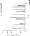
- Figs. 11 to 16 illustrate experimental results that have been obtained with a setup as illustrated in Fig. 1 .
- Figs. 11 and 12 show time-resolved ICP-MS peak traces of monodisperse droplets containing 133 Cs ( Fig. 11 ) and 232 Th ( Fig. 12 ).
- Droplets of 66 ⁇ m diameter were generated at 20 Hz from a solution comprising 20 ppb each of both 133 Cs and 232 Th, using a droplet generator. All the dispensed droplets arrived in the plasma and were successfully detected by ICP-MS.
- 133 Cs possesses an ionization energy of 3.89 eV and 232 Th an ionization energy of 6.31 eV.
- Figs. 13 and 14 show diagrams illustrating the dependency of the ion signal on analyte mass for droplets containing 133 Cs ( Fig. 11 ) and 232 Th ( Fig. 12 ). These results were obtained by investigating monodisperse droplets having different analyte concentrations as follows: 2 ppb (leftmost data point), 5 ppb, 10 ppb and 20 ppb (rightmost data point), for both 133 Cs and 232 Th. Both diagrams exhibit a linear relationship between analyte mass and ion signal, indicating complete desolvation, vaporization, dissociation and ionization of the droplets using the vertical plasma configuration of the present invention.
- Figs. 15 shows a time-resolved ICP-MS peak trace for a Cd-enriched Chinese Hamster Ovary (CHO) cell suspension in phosphate-buffered saline.
- Fig. 16 shows a time-resolved ICP-MS peak trace for a Pb-enriched Chinese Hamster Ovary (CHO) cells suspension in water.
- ICP source than the two types discussed above can be employed.
- the sample can be split up into small droplets or particles in other manners than discussed above. Any type and orientation of mass spectrometer can be employed.
Landscapes
- Chemical & Material Sciences (AREA)
- Analytical Chemistry (AREA)
- Physics & Mathematics (AREA)
- Dispersion Chemistry (AREA)
- Engineering & Computer Science (AREA)
- Plasma & Fusion (AREA)
- Health & Medical Sciences (AREA)
- Life Sciences & Earth Sciences (AREA)
- Biochemistry (AREA)
- General Health & Medical Sciences (AREA)
- General Physics & Mathematics (AREA)
- Immunology (AREA)
- Pathology (AREA)
- Other Investigation Or Analysis Of Materials By Electrical Means (AREA)
- Electron Tubes For Measurement (AREA)
Abstract
An ICP source (100) for generating ions using an inductively coupled plasma is configured to be coupled to a mass spectrometer (200). The sample is introduced into the plasma along a downwards-pointing vertical direction (G) under the action of gravity. In this manner, the sample can reach the plasma regardless of its condition, e.g., regardless of droplet or particle size. Transport efficiencies of up to 100% can be achieved. The ICP source can be directly coupled to a flow cytometer.
Description
- The present invention relates to an inductively coupled plasma (ICP) ion source configured to be coupled to a mass spectrometer. The invention further relates to an ionization system comprising the ICP source, to an ICP-mass spectrometry system, and to a corresponding method of ICP mass spectrometry.
- Inductively coupled plasma mass spectrometry (ICP-MS) is an analytical technique for detecting and quantifying trace amounts of elements and/or isotope ratios in a sample. This is achieved by dissociating and ionizing the sample components in an ICP source using an inductively coupled plasma and then separating and detecting the ions using a mass spectrometer. ICP-MS systems were first introduced commercially in the early 1980s.
- An ICP source usually comprises a plasma torch to confine the plasma discharge by means of a directed gas flow and to carry a sample aerosol into the center of the plasma discharge for dissociation and ionization. The sample aerosol is usually transported to the plasma discharge through a central injector tube of the torch. In almost all prior-art ICP-MS systems, the torch axis is oriented horizontally, and the sample aerosol accordingly is transported to the plasma discharge using a carrier gas that flows horizontally through a horizontal injector tube. The carrier gas flow must be carefully adjusted to optimize sample transport to the plasma discharge and to ensure that the sample reaches a position within the plasma from which it can be extracted into the mass spectrometer system at highest possible ion yield.
- Even at optimized carrier gas flow rates, transport efficiencies can be very low in prior-art ICP-MS systems. This is particularly true for aerosols that contain relatively large objects like large droplets, particles or cells. In this connection, it is to be noted that prior-art sample introduction systems for liquid samples and suspensions typically comprise a pneumatic nebulizer, which creates a broad droplet size distribution, often followed by a spray chamber for removing larger droplets, e.g., droplets having more than 10 µm diameter, from the aerosol (see, e.g., J. Olesik and L. Bates, "Characterization of aerosols produced by pneumatic nebulizers for inductively coupled plasma sample introduction: effect of liquid and gas flow rates on volume based drop size distributions", Spectrochimica Acta Part B: Atomic Spectroscopy, 1995, 50, 285-303, DOI 10.1016/0584-8547(94)00151-K). With such systems, the efficiency of sample transfer into the ICP is typically in the range of 3 and 30%, depending on the nebulizer used. Specific nebulizers operating at very low liquid flow rates (< 50 µL/min) may achieve higher efficiency, but their susceptibility to clogging makes them useful only for dilute solutions and suspensions with particles or cells in the low µm range.
- There have been various attempts to improve sample introduction into an ICP-MS system. For instance, sample introduction systems using a monodisperse microdroplet generator were disclosed in the following documents: S. Gschwind et al., "Capabilities of inductively coupled plasma mass spectrometry for the detection of nanoparticles carried by monodisperse microdroplets", J. Anal. At. Spectrom., 2011, 26, 1166-1174, DOI: 0.1039/C0JA00249F; S. Gschwind et al., "Mass quantification of nanoparticles by single droplet calibration using inductively coupled plasma mass spectrometry", Anal. Chem. 2013, 85, 5875-5883, DOI: 10.1021/ac400608c; K. Shigeta et al., "Application of a microdroplet generator for an ICP-sector field mass spectrometer - optimization and analytical characterization", J. Anal. At. Spectrom. 2013, 28, 646-656, DOI: 10.1039/c2ja30207a. While these documents disclose that droplets can pass vertically through a so-called falling tube, the axis of the plasma torch is still oriented horizontally, and the droplets are eventually transported to the plasma in a horizontal direction using a horizontal carrier gas stream.
- P. Verboket et al., "A New Microfluidics-Based Droplet Dispenser for ICPMS", Analytical Chemistry 2014, 86, p. 6012, DOI: 10.1021/ac501149a discloses a microfluidic dispenser for introducing microdroplets into an ICP-MS. The chip is coupled with a cyclonic adapter, a heated steel tube, a membrane desolvator and an ICP-MS unit. Although the droplets fall vertically through the steel tube, the ICP-MS unit is oriented horizontally in the usual manner, and the droplets are introduced into the ICP-MS unit along a horizontal direction.
-
WO 2008/080224 A1 discloses a flow cytometer that is coupled to an ICP-MS system. The plasma torch of the ICP source is oriented horizontally in the usual manner. - An exception from the usual horizontal orientation of the plasma torch in an ICP-MS system is reported in I.I. Stewart and J.W. Olesik, "Time resolved measurements with Single Droplet Introduction to Investigate Space-Charge Effects in Plasma Mass Spectrometry", J. Am. Soc. Mass Spectrom. 1999, 10, 159-174. The authors propose a vertically upwards-pointing orientation of the plasma torch. The ions from the plasma are analyzed with a vertically upwards-oriented mass spectrometer whose interface is coupled with the plasma torch. This arrangement was reported to achieve better signal stability and reproducibility regarding the droplet signals than prior-art systems. However, the vertically upwards-pointing setup requires very careful adjustment of the operating conditions in order to correctly transport the droplets into the plasma.
- In the context of inductively coupled plasma optical emission spectroscopy (ICP-OES), different orientations of the plasma torch have been proposed. For instance, an upwardly pointing plasma torch is disclosed in A. Murtazin, S. Groh, and K. Niemax, "Measurement of element mass distributions in particle ensembles applying ICP-OES", J. Anal. At. Spectrom. 2010, 25, 1395-1401, DOI: 10.1039/c004946h. The plasma torch is employed for optical emission spectroscopy only and is incompatible with a mass spectrometer.
US 4,766,287 ,US 2015/255262 A1 andUS 2016/0270201 A1 also disclose upwardly pointing plasma torches with a focus on applications in optical emission spectroscopy. - M. Schild et al., "Replacing the Argon ICP: Nitrogen Microwave Inductively Coupled Atmospheric-Pressure Plasma (MICAP) for Mass Spectrometry", Anal. Chem. 2018, 90(22), 13443-13450, DOI: 10.1021/acs.analchem.8b03251 discloses a nitrogen-sustained ICP source that is operated at microwave frequencies, coupled with a time-of flight mass spectrometer. The plasma source is called a "microwave inductively coupled atmospheric-pressure plasma (MICAP) source". It comprises an annular dielectric resonator made of a technical ceramic, which, when immersed in a microwave field, exhibits a bulk polarization current around the ring that oscillates with the microwaves' frequency. The dielectric resonator ring does not have a significant net electric potential, and energy coupling to the plasma is purely inductive. The plasma torch of the MICAP source is oriented horizontally.
US 2016/0025656 A1 discloses the MICAP source in more detail. -
WO 97/13141 -
US 2014/0287162 discloses a downwardly oriented microwave plasma source for materials processing, e.g., for applying surface coatings or for powder production. Downwardly oriented plasma sources for materials processing are also disclosed inUS 2005/0211018 A1 ,US 2014/0217630 A1 ,US 2013/0270261 A1 andUS 2013/0118304 A1 . These setups are designed for industrial applications in materials processing and are clearly unsuitable for elemental analysis of samples. All the less are these setups suitable to be coupled to a mass spectrometer. - In a first aspect, it is an object of the present invention to provide an ICP source configured to be coupled to a mass spectrometer, the ICP source enabling improved sample introduction into the plasma discharge.
- This object is achieved with an ICP source according to
claim 1. Further embodiments of the invention are laid down in the dependent claims. - The invention provides an ICP source for generating ions from a sample using an inductively coupled plasma. The ICP source is configured to be coupled to a mass spectrometer. According to the invention, the ICP source is configured to allow introduction of the sample into the plasma along a downwards-pointing vertical direction.
- Sample introduction into the plasma therefore takes place from the top. The sample is introduced into the plasma along the direction of the gravity vector. Thereby, sample introduction is less sensitive to the carrier gas flow rate. It is even conceivable to introduce the sample without using any carrier gas flow at all, the sample trajectories before the entry of the sample into the plasma being determined exclusively by gravity. Thereby significant amounts of carrier gas can be saved, which is of some significance especially when the carrier gas is an expensive noble gas like argon or an argon-helium mixture. The size of droplets or objects (e.g. cells) that can reach the plasma is essentially only limited by the dimensions of the sample introduction system. Because impact of droplets or objects with the walls of the sample introduction system can be avoided, the proposed arrangement can reach up to 100% transport efficiency. Samples of any type and in any condition can be investigated, e.g., aerosols or single droplets or objects like solid particles or cells. High flexibility in terms of sample size, aerosol humidity and sample amount can be obtained. For instance, eukaryotic cells, whose diameter is typically about 10-150 µm, can reach the plasma independent of their size or mass. Droplets will reach the plasma independent of how much of the solvent had been evaporated during transport within the carrier gas.
- Extraction of ions from the plasma can likewise take place along the downwards-pointing vertical direction. To this end, the ICP source can have an extraction opening that is open towards the bottom, the extraction opening being located below the region where the plasma is formed in the ICP source. After extraction, the ions can be transferred to a mass spectrometer having any arbitrary orientation, using known ion optics elements such as electrostatic mirrors and/or bending magnets.
- Normally the ICP source will comprise a plasma torch, i.e., an arrangement of (usually at least three, concentric) tubes for feeding gases to the region of the plasma discharge. One of these tubes usually serves for feeding the sample to the plasma. This tube is often called the injector tube. The injector tube is usually arranged centrally in the plasma torch and surrounded by other tubes. In the present invention, the longitudinal axis of the injector tube, if present, is oriented vertically, the injector tube having an upper end configured to receive the sample and a lower end configured to introduce the sample into the plasma. The extraction opening for extracting ions from the plasma can then advantageously be located below the lower end of the injector tube.
- Since in the present invention the plasma torch is arranged above the region of the plasma discharge, components such as the connections for feeding gases to the plasma torch can be arranged above the plasma discharge. In order to protect such components from convective heat that is generated by sustaining the plasma discharge, the ICP source can comprise a metallic cooling plate that at least partially surrounds the plasma torch and thereby shields these components from the heat that is due to the plasma discharge. The cooling plate preferably extends in a horizontal plane. It can have a cutout that is configured to receive the plasma torch when the cooling plate is installed.
- The ICP source can comprise a cooling system for actively cooling the metallic cooling plate by a forced flow of air or water through the metallic cooling plate and/or through an additional component that is connected to the metallic cooling plate, e.g., through one or more metallic panels which connect the cooling plate to a torch box that encloses the plasma torch. To this end, the cooling plate and/or the component to which the cooling plate is connected can be provided with one or more bores extending in the plane of the cooling plate or the additional component for passing a flow of air or water through these bores.
- The ICP source will generally comprise an electromagnetic coupling element for feeding energy to the plasma by inductive coupling, so as to sustain the plasma discharge. The electromagnetic coupling element can, in particular, be an induction coil coupled to an RF generator via electrical conductors. Such an induction coil is usually operated in the frequency range between 10 and 100 MHz, e.g., at 27 or 40 MHz. In other embodiments, the ICP source can employ a ring-shaped dielectric resonator that is immersed in a microwave field, which can be generated, e.g., by a magnetron. The microwave field can be in a frequency range of, e.g., 1 to 10 GHz, a typical frequency being 2.45 GHz. An example is the so-called MICAP source disclosed in M. Schild et al., "Replacing the Argon ICP: Nitrogen Microwave Inductively Coupled Atmospheric-Pressure Plasma (MICAP) for Mass Spectrometry", Anal. Chem. 2018, 90(22), 13443-13450, DOI: 10.1021/acs.analchem.8b03251 and
US 2016/0025656 A1 , see section "Prior Art" above. - Regardless of the type of electromagnetic coupling element, the coupling element defines a longitudinal axis, which advantageously extends vertically. The coupling element can surround a lower end portion of the plasma torch. If a metallic cooling plate is present, the coupling element can be arranged below the cooling plate.
- The ICP source can further comprise an RF generator for feeding energy to the electromagnetic coupling element. The term "RF generator" is to be understood broadly as encompassing any AC generator operating in a frequency range of at least 10 MHz to 10 GHz.
- If the electromagnetic coupling element is an induction coil, it is advantageous to connect the induction coil to the RF generator via at least one metal bar (preferably two parallel metal bars) that extend in a horizontal direction. This makes it possible to place the induction coil at a horizontal distance from the RF generator to gain space. The metal bars can be made of any highly conducting material, in particular, copper, silver or gold, to minimize ohmic losses between the RF generator and the induction coil.
- The ICP source can be combined with an aerosolization device to form an ionization system for obtaining ions from a bulk sample. Advantageously, the ICP source is coupled to the aerosolization device in such a manner that the aerosolized sample is transferred from the aerosolization device to the ICP source along the downwards-pointing vertical direction. In this manner the above-discussed advantages of the presently proposed vertical design of the ICP source are preserved also during the transfer of the aerosolized sample to the ICP source.
- Depending on the type of sample, the aerosolization device can be constructed in different manners. In some embodiments, the aerosolization device can comprise a droplet generator for aerosolizing the sample by creating droplets. A vertically oriented falling tube can be coupled to the droplet generator. The falling tube allows the droplets to be transported downwards under the action of gravity. During their passage through the falling tube, the droplets can be reduced in size or completely dried by solvent evaporation. To this end, the falling tube can have a sample inlet, a gas inlet and an outlet, and the falling tube can be configured to receive droplets from the droplet generator at its sample inlet and to receive a gas flow at its gas inlet, so as to allow the droplets to move downwards under the action of gravity while being reduced in size by vaporization of the solvent into the gas flow. The outlet of the falling tube can be directly or indirectly connected to an inlet of the ICP source in such a manner that the aerosolized sample is transferred from the falling tube to the ICP source along the downwards-pointing vertical direction, without requiring horizontal sample transport by a carrier gas flow, as would be required in the prior art.
- In other embodiments, the aerosolization device can comprise a nebulizer for aerosolizing the sample and a spray chamber coupled to the nebulizer, the spray chamber having a downwards-pointing outlet, the outlet of the spray chamber being connected to an inlet of the ICP source in such a manner that the aerosolized sample is transferred from the spray chamber to the ICP source along the downwards-pointing vertical direction.
- In yet other embodiments, the aerosolization device can comprise a laser ablation cell, the laser ablation cell having a downwards-pointing outlet, the outlet of the laser ablation cell being connected to an inlet of the ICP source in such a manner that the aerosolized sample is transferred from the laser ablation cell to the ICP source along the downwards-pointing vertical direction. Various configurations of the laser ablation cell are conceivable.
- Other types of aerosolization devices can also be employed.
- In yet other embodiments, no separate aerosolization device is employed. Instead, the injector tube of the plasma torch can form a direct injection nebulizer for splitting a bulk sample liquid into droplets within the plasma torch, i.e., immediately before the sample enters the plasma.
- The ICP source of the present invention can be combined with a flow cytometer. Typically, in a flow cytometer the sample is injected into a flow of a sheath fluid. The flow is broken up into droplets by a vibrating nozzle, each droplet containing ideally one cell or particle.
- The flow cytometer then analyzes the optical properties of the cell or particle just prior to or shortly after release of the droplet from the nozzle. The ICP source can be coupled to the flow cytometer in such a manner that the sample is transferred from the flow cytometer to the ICP source along the downwards-pointing vertical direction. In this manner, maximum transport efficiency from the flow cytometer to the ICP source can be ensured. All cell/particle sizes will fall down into the ICP source and can be analyzed by ICP-MS. This prevents cell or particle analysis being biased with respect to size or mass. The flow cytometry results for each individual cell or particle can be correlated with the mass spectrometry results for the very same cell or particle, thereby maximizing the information that can be obtained from a single cell or particle. To this end, the ICP-MS system may comprise a correlator configured to receive flow cytometry information from the flow cytometer and mass spectrometry information from the mass spectrometer and to correlate the flow cytometry information with the mass spectrometry information to obtain combined flow cytometry and mass spectrometry information for individual cells or particles.
- Optionally the flow cytometer can be coupled to a cell sorter. In this case, objects (in particular, cells or nanoparticles) that have passed the cell sorter are transferred from the cell sorter to the ICP source along the downwards-pointing vertical direction. In particular, the cell sorter can be an electrostatic cell sorter, wherein an electrical charge is provided to the droplet depending on the result of the flow cytometry analysis. The charged droplet then falls through an electrostatic deflection system that diverts droplets into different containers depending on their charge. Instead of collecting droplets of a particular charge state, these droplets can be directly passed on to the ICP source by allowing the droplets to vertically fall down into inlet of the ICP source.
- The flow cytometer or cell sorter can be directly coupled to the ICP source. Optionally a falling tube as described above can be provided between the flow cytometer or cell sorter and the ICP source in order to reduce the size of the droplets before they enter the plasma.
- The present invention also provides an ICP-MS system, comprising the ICP source of the present invention and a mass spectrometer coupled to the ICP source for receiving ions from the ICP source. The mass spectrometer can have any arbitrary orientation in space, and one or more ion optics elements can optionally be present to deflect the ions into the mass spectrometer after extraction from the ICP source.
- In another aspect, the present invention provides a method of mass spectrometry comprising:
- sustaining a plasma using an ICP source;
- introducing a sample into the plasma so as to generate ions from the sample; and
- analyzing the mass-to-charge spectrum of ions that have been extracted from the plasma, using a mass spectrometer that is coupled to the ICP source,
- wherein the sample is introduced into the plasma along a downwards-pointing vertical direction.
- In preferred embodiments, the ions are extracted from the plasma along the downwards-pointing vertical direction as well in order to transfer the ions to the mass spectrometer.
- The method can further comprise:
- aerosolizing the sample using an aerosolization device; and
- transferring the aerosolized sample from the aerosolization device to the ICP source along the downwards-pointing vertical direction.
- In particular, the method can comprise aerosolizing the sample using a droplet generator, passing the aerosolized sample through a vertically oriented falling tube along the downwards-pointing vertical direction, and introducing the aerosolized sample into an inlet of the ICP source along the downwards-pointing vertical direction.
- In other embodiments, the method can comprise aerosolizing the sample using a nebulizer, passing the aerosolized sample through a spray chamber, the spray chamber having a downwards-pointing outlet, and introducing the aerosolized sample into an inlet of the ICP source along the downwards-pointing vertical direction.
- In yet other embodiments, the method can comprise aerosolizing the sample using a laser ablation cell, the laser ablation cell having a downwards-pointing outlet, and transferring the aerosolized sample from the outlet of the laser ablation cell to the plasma along the downwards-pointing vertical direction.
- In yet other embodiments, the method can comprise:
- analyzing at least one property of the sample using a flow cytometer; and
- transferring the sample from the flow cytometer into the ICP source along the downwards-pointing vertical direction.
- The method can further comprise receiving flow cytometry information from the flow cytometer and mass spectrometry information from the mass spectrometer and correlating the flow cytometry information with the mass spectrometry information to obtain combined flow cytometry and mass spectrometry information for individual cells or particles.
- In yet other embodiments, the method can comprise:
- sorting sample droplets according to at least one property, in particular, according to an optical property, using a cell sorter; and
- transferring the sample droplets from the cell sorter to the ICP source along the downwards-pointing vertical direction.
- Preferred embodiments of the invention are described in the following with reference to the drawings, which are for the purpose of illustrating the present preferred embodiments of the invention and not for the purpose of limiting the same. In the drawings,
- Fig. 1
- shows a schematic sketch of an ICP-MS system according to an embodiment of the present invention;
- Fig. 2
- shows an enlarged view of a portion of the ICP-MS system of
Fig. 1 together with a highly schematic sketch of a cell sorter based on flow cytometry; - Fig. 3
- shows a top view of the cooling plate of the ICP source in
Fig. 1 ; - Fig. 4
- shows a plasma torch configured as a direct injection nebulizer;
- Fig. 5
- shows a plasma torch coupled to a falling tube;
- Fig. 6
- shows a plasma torch coupled to a total consumption sample introduction system;
- Fig. 7
- shows a plasma torch coupled to a laser ablation cell according to a first embodiment;
- Fig. 8
- shows a plasma torch coupled to a laser ablation cell according to a second embodiment;
- Fig. 9
- shows a TOF mass spectrometer suitable to be coupled to the ICP source in
Fig. 1 ; - Fig. 10
- shows a MICAP source according to an embodiment of the present invention;
- Fig. 11
- shows a time-resolved ICP-MS peak trace of monodisperse droplets containing 133Cs;
- Fig. 12
- shows a time-resolved ICP-MS peak trace of monodisperse droplets containing 232Th;
- Fig. 13
- shows a calibration curve illustrating the dependency of the ion signal on analyte mass for droplets comprising 133Cs;
- Fig. 14
- shows a calibration curve illustrating the dependency of the ion signal on analyte mass for droplets comprising 232Th;
- Fig. 15
- shows a time-resolved ICP-MS peak trace for a Cd-enriched Chinese Hamster Ovary (CHO) cells suspension in phosphate-buffered saline; and
- Fig. 16
- shows a time-resolved ICP-MS peak trace for a Pb-enriched Chinese Hamster Ovary (CHO) cells suspension in water.
-
Fig. 1 illustrates, in a highly schematic manner, an ICP-MS system according to an exemplary embodiment of the present invention. The ICP-MS system comprises anICP source 100 for generating an argon plasma and amass spectrometer 200 coupled to an outlet end of the ICP source. - In the present example, the
ICP source 100 comprises anRF generator 110 mounted on anelevator 150 so as to be adjustable in height h relative to themass spectrometer 200. TheRF generator 110 feeds an alternating current in a frequency range of typically 10 to 100 MHz, e.g. at 27 MHz or 40 MHz, to a resonant circuit comprising acapacitor 112 and aninduction coil 115. Thecapacitor 112 and one end of theinduction coil 115 are electrically connected via avertical metal bar 113 and via ahorizontal metal bar 114 preferably made of a highly conductive metal like copper, silver or gold, supported by aPTFE support 116. Likewise, the other end of theinduction coil 115 is electrically connected to the RF generator via anotherhorizontal metal bar 114 and anothervertical metal bar 113. By using thehorizontal metal bars 114, it becomes possible to place theinduction coil 115 in a location that is at a sufficiently large lateral distance from theRF generator 110 so as to arrange amass spectrometer 200 below theinduction coil 115 without interfering with theRF generator 110. A typical length of the horizontal metal bears 114 is 10 to 50 cm, in particular, about 20 cm. - The
ICP source 100 further comprises atorch box 120. Thetorch box 120 comprises a housing made of an electrically conducting metal in order to electromagnetically shield its interior. Aplasma torch 130, which will be described in more detail below in conjunction withFig. 2 , is arranged in thetorch box 120 together with theinduction coil 115, thehorizontal metal bars 114 and the vertical metal bars 113. Theinduction coil 115 surrounds a lower portion of theplasma torch 130. Above theinduction coil 115, ahorizontal cooling plate 140 is arranged. Thecooling plate 140 is supported in thetorch box 120 by two vertical, water-cooledmetal panels 141. Thecooling plate 140 protects the components in thetorch box 120 that are arranged above theinduction coil 115 from convective heat generated during operation of the ICP source. Aventilation grid 121 allows gases and heat to escape from thetorch box 120. - At its
outlet end 122, thetorch box 120 is open towards the bottom and forms an extraction opening for interfacing theICP source 100 to themass spectrometer 200. The mass spectrometer comprises avacuum interface 210 that will be explained in more detail below in conjunction withFig. 2 , followed by anion optics unit 215, aninlet baffle 220, aquadrupole mass analyzer 230, anexit baffle 240, and adetector 250. Amechanical pump 261 evacuates the region of thevacuum interface 210. Turbo-molecular pumps 262 evacuate the region of theion optics unit 215,mass analyzer 230 anddetector 250. The setup of such a type of mass spectrometer is well known in the art; however, usually the extraction of ions from the ion source occurs horizontally, whereas the axis of ion extraction in the setup ofFig. 1 is oriented vertically downwards. -
Fig. 2 illustrates theplasma torch 130 and theinterface 210 to themass spectrometer 200 in more detail. Theplasma torch 130 is constructed in a manner well known in the art. It comprises threeconcentric tubes outer tube 133 and themiddle tube 132 at a flow rate of typically 12 to 17 l/min. A second gas flow is passed between theintermediate tube 132 and thecentral tube 131 at a flow rate of 1 l/min and is used to sustain the plasma and adjust the position of the base of the plasma relative to the end of these tubes. Thecentral tube 131, often called the injector tube, is employed for feeding the sample to the plasma. - The
plasma torch 130 is positioned centrally in theinduction coil 115. When RF power is applied to theinduction coil 115, an intense electromagnetic field is created inside theinduction coil 115. A high-voltage spark is used to ionize a fraction of gas inside theinduction coil 115, and by acceleration of electrons and ions through the RF electromagnetic field a plasma can be sustained. The coupling between the coil and the plasma is inductive, i.e., energy transfer occurs predominantly by the magnetic field produced by the oscillating current in the induction coil, and only to a small extent by electric field gradient along the induction coil. - The sample is introduced into the plasma through the central tube (injector tube) 131 under the action of gravity. The plasma is sufficiently hot to progressively evaporate the sample, dissociate the sample, and ionize the elements contained in the sample.
- The
interface 210 to themass spectrometer 200 is formed between afirst baffle 211 that comprises a small opening in a so-calledsampler cone 212 and asecond baffle 213 that comprises a small opening in a so-calledskimmer cone 214. A mechanical pump is connected to evacuate the interspace between the first andsecond baffles sampler cone 212 and theskimmer cone 214 enter a space at high vacuum and are focused by anion optics unit 215 into the mass analyzer. -
Fig. 2 further schematically illustrates how the ICP-MS system of the present invention can be coupled to anelectrostatic cell sorter 320, which in turn is coupled to aflow cytometer 310. Such a combination of a flow cytometer cooperating with a cell sorter is known in the art as a fluorescent-activated cell sorter. In theflow cytometer 310, acell suspension 311 is fed to anozzle 312. Droplets containing single cells are created by thenozzle 312. Each droplet is interrogated by one or more laser beams created by one ormore lasers 313. Light along the direction of illumination as well as fluorescent light emitted by the droplet is detected by anoptical detection system 314 and analyzed by ananalyzer 315. Depending on the result of the analysis, theanalyzer 315 applies a positive or negative charge to the nozzle tip or to a charging electrode so as to apply a charge of predefined sign to the droplet before it is discharged from the nozzle. In thecell sorter 320, the droplets are deflected according to their charge state bydeflection plates 321 to which a DC voltage is applied. Depending on their charge state, droplets either end up incollection containers 322 or in asample inlet 323. From thesample inlet 323, the droplets are transferred downwards directly into theinjector tube 131 of theplasma torch 130, where they fall down vertically under the action of gravity. - The
cell sorter 320 can also be omitted, and droplets that exit theflow cytometer 310 can be directly introduced into the plasma by placing the inlet of the ICP source directly under the output nozzle of the flow cytometer. No additional nebulization system is needed, and a transport efficiency of 100% can be obtained. - Regardless of whether the droplets are sorted or not, the results obtained from the
flow cytometer 310 can be correlated with the results from themass spectrometer 200 for each individual droplet. By combining flow cytometry with mass spectrometry in the presently proposed configuration, the number of cellular parameters that can be quantified simultaneously is increased when compared to flow cytometry alone or to mass spectrometry alone. To this end, the analyzer 305 can be configured to carry out correlations between flow cytometry and mass spectrometry results, or a separate correlator can be provided. -
Fig. 3 illustrates thecooling plate 140 and thevertical metal panels 141 in greater detail. Thecooling plate 140 has acutout 142 for accommodating the plasma torch when the cooling plate is installed. The vertical panels are provided with a plurality of channels or bores 143, which extend in-plane within each of the panels, for passing cool air or water through the bores in order to actively cool the cooling plate. -
Fig. 4 illustrates a variant in which the plasma torch 130' is configured as a so-called direct injection high-efficiency nebulizer (DIHEN), which enables direct sample introduction into the plasma without the need of a separate aerosolization device. A high-efficiency nebulizer 134 replaces the injector tube in the plasma torch 130'. Thereby the sample can be directly introduced into the plasma without the need of prior aerosolization. 100% transport efficiency is thereby obtained. Such a direct injection nebulizer is known per se (A. Montaser, "Inductively Coupled Plasma Mass Spectrometry", Wiley-VCH: Washington DC, 1998). However, normally it is operated in a horizontal configuration, whereas in the present invention the direct injection nebulizer is operated in a vertical configuration. -
Figs. 5 to 8 illustrate four examples of aerosolization devices coupled to theplasma torch 130 of the ICP source shown inFig. 1 . These Figures are schematic, and relative dimensions of the components shown in these Figures are not to scale. - In
Fig. 5 , a droplet delivery and low-temperature desolvation system 410 is illustrated. Adroplet dispenser 411 is connected to aflow adapter 412 that sits on top of a so-called fallingtube 413. The fallingtube 413 is a 40 cm long stainless steel tube with an inner diameter of 4 mm. A mixture of argon and helium is used to desolvate the droplets inside the fallingtube 413. The desolvation of the droplets leads to reduced local cooling of the plasma. For more details, reference is made to S. Gschwind et al., "Capabilities of inductively coupled plasma mass spectrometry for the detection of nanoparticles carried by monodisperse microdroplets", J. Anal. At. Spectrom., 2011, 26, 1166-1174, DOI: 0.1039/C0JA00249F. Whereas in the prior art the aerosolized sample that leaves the fallingtube 413 is transported horizontally to the ICP source using a carrier gas flow, in the present example the aerosolized sample is directly introduced into theinjector tube 131 of the plasma torch along the downward direction, without requiring an additional carrier gas flow. In this manner, all sample droplets or particles that leave the fallingtube 413 will reach the plasma, independently of their size, and independently of the gas flow rate. - In
Fig. 6 , aerosolization is carried out by a so-called total consumptionsample introduction system 420. Alow flow nebulizer 421, usually operated at a liquid flow rate of less than 10 µL/min, is coupled to a smallvolume spray chamber 422, which forces the droplets generated by thenebulizer 421 down along its central axis and prevents the droplets from sticking to the walls of thespray chamber 422. Thespray chamber 422 is open at its bottom to form an outlet. The outlet is directly coupled to theinjector tube 131 of theplasma torch 130. - In
Fig. 7 , asolid sample 432 is aerosolized in alaser ablation cell 430 using alaser 431. Thelaser 431 shines an intense pulsed laser beam onto the rear side of thesample 432, which faces away from the ICP source. The induced shock wave leads to an ejection of sample material, which falls down into theinjector tube 131 of the plasma torch 130 ("rear side ablation"). -
Fig. 8 illustrates aerosolization using alaser ablation cell 440 according toUS 9,922,811 B2 laser 441 shines laser onto a surface of asolid sample 442, causing sample material to be ablated. The ablated material enters aflow channel 443, from where it is directly transferred downwards into theinjector tube 131 of theplasma torch 130. For more details of thelaser ablation cell 440 and its mode of operation, reference is made toUS 9,922,811 B2 flow channel 443 is oriented horizontally and the laser beam impinges onto the sample surface vertically, in the present example theflow channel 443 is oriented vertically, and the laser beam is oriented horizontally. - The presently proposed ICP source can be used with any type and configuration of mass spectrometer. For instance,
Fig. 9 illustrates a TOF mass spectrometer 200' that can be used in conjunction with the ICP source shown inFigs. 1 and2 . Theinterface 210 is constructed in the same manner as inFigs. 1 and2 . Ions extracted from the ICP source through theinterface 210 are passed through anotch filter 260 and anextractor 270 into aTOF mass analyzer 280. Any other type and configuration of mass spectrometer can be employed. For instance, a quadrupole mass spectrometer, sector field mass spectrometer or an ion trap mass spectrometer can be used instead. If required, electrostatic mirrors and/or bending magnets can be used to deflect the ions into the mass spectrometer. -
Fig. 10 illustrates a microwave inductively coupled atmospheric-pressure plasma (MICAP)source 500 that is configured for vertical sample introduction. The MICAP source comprises an RF generator (microwave generator) 510 in the form of a magnetron. Afan 511 provides cooling for themagnetron 510. Anantenna 512 couples the microwave field into the interior of thetorch box 520. An annulardielectric resonator 515 is immersed in the microwave field. The resonator exhibits a bulk polarization current around the ring, which oscillates with the microwaves' frequency. Aplasma torch 530 is arranged above theresonator 515. Theplasma torch 530 is constructed in the same manner as theplasma torch 130 that has been described in conjunction withFig. 2 . Nitrogen gas is passed into the region of the center of theresonator 530. A nitrogen plasma is sustained by the electromagnetic field in the center of theresonator 515 by inductive coupling. For details, reference is made toUS 2016/0025656 A1 and to M. Schild et al., "Replacing the Argon ICP: Nitrogen Microwave Inductively Coupled Atmospheric-Pressure Plasma (MICAP) for Mass Spectrometry", Anal. Chem. 2018, 90(22), 13443-13450, DOI: 10.1021/acs.analchem.8b03251. Whereas in the prior art the plasma torch of the MICAP source is oriented horizontally, in the present example theplasma torch 530 is oriented vertically, allowing introduction of the sample through thecentral tube 531 along the direction of the gravity vector. -
Figs. 11 to 16 illustrate experimental results that have been obtained with a setup as illustrated inFig. 1 . -
Figs. 11 and 12 show time-resolved ICP-MS peak traces of monodisperse droplets containing 133Cs (Fig. 11 ) and 232Th (Fig. 12 ). Droplets of 66 µm diameter were generated at 20 Hz from a solution comprising 20 ppb each of both 133Cs and 232Th, using a droplet generator. All the dispensed droplets arrived in the plasma and were successfully detected by ICP-MS. It is noted that 133Cs possesses an ionization energy of 3.89 eV and 232Th an ionization energy of 6.31 eV. These results prove that the ICP-MS system of the present invention can readily achieve 100% transport efficiency. -
Figs. 13 and 14 show diagrams illustrating the dependency of the ion signal on analyte mass for droplets containing 133Cs (Fig. 11 ) and 232Th (Fig. 12 ). These results were obtained by investigating monodisperse droplets having different analyte concentrations as follows: 2 ppb (leftmost data point), 5 ppb, 10 ppb and 20 ppb (rightmost data point), for both 133Cs and 232Th. Both diagrams exhibit a linear relationship between analyte mass and ion signal, indicating complete desolvation, vaporization, dissociation and ionization of the droplets using the vertical plasma configuration of the present invention. -
Figs. 15 shows a time-resolved ICP-MS peak trace for a Cd-enriched Chinese Hamster Ovary (CHO) cell suspension in phosphate-buffered saline.Fig. 16 shows a time-resolved ICP-MS peak trace for a Pb-enriched Chinese Hamster Ovary (CHO) cells suspension in water. These traces illustrate that cells can be successfully introduced into the plasma using the vertical configuration of the present invention. Since a transport efficiency of 100% is expected, it is believed that "missing" peaks are due to droplets that did not contain cells. On the other hand, it cannot be excluded that other droplets contained multiple cells. - Many modifications are possible without leaving the scope of the present invention. In particular, other types of ICP source than the two types discussed above can be employed. The sample can be split up into small droplets or particles in other manners than discussed above. Any type and orientation of mass spectrometer can be employed.
-
- 100
- ICP source
- 110
- RF generator
- 112
- plate capacitor
- 113
- vertical metal bar
- 114
- horizontal metal bar
- 115
- induction coil
- 116
- PTFE support
- 120
- torch box
- 121
- ventilation grid
- 122
- outlet end
- 130, 130'
- plasma torch
- 131
- central tube (injector tube)
- 132
- middle tube
- 133
- outer tube
- 134
- nebulizer
- 140
- cooling plate
- 141
- vertical panel
- 142
- cutout
- 143
- bore
- 150
- elevator
- 200
- quadrupole mass spectrometer
- 200'
- TOF mass spectrometer
- 210
- interface
- 211
- first baffle
- 212
- sampler cone
- 213
- second baffle
- 214
- skimmer cone
- 215
- ion optics unit
- 220
- inlet baffle
- 230
- quadrupole mass analyzer
- 240
- outlet baffle
- 250
- detector
- 260
- notch filter
- 270
- extractor
- 280
- TOF mass analyzer
- 261
- mechanical pump
- 262
- turbomolecular pump
- 310
- flow cytometer
- 311
- slurry
- 312
- nozzle
- 313
- laser
- 314
- detection system
- 315
- analyzer
- 320
- cell sorter
- 321
- deflection plate
- 322
- collection container
- 323
- sample inlet
- 410
- droplet delivery and desolvation system
- 411
- droplet dispenser
- 412
- flow adapter
- 413
- falling tube
- 420
- total consumption sample introduction system
- 421
- nebulizer
- 422
- spray chamber
- 430
- laser ablation cell
- 431
- laser
- 432
- sample
- 440
- laser ablation cell
- 441
- laser
- 442
- sample
- 443
- flow channel
- 500
- MICAP source
- 510
- RF generator (magnetron)
- 511
- fan
- 512
- antenna
- 515
- resonator
- 520
- torch box
- 530
- plasma torch
- 531
- injector tube
- h
- height
- G
- direction of gravity
Claims (15)
- An ICP source for generating ions from a sample using an inductively coupled plasma, the ICP source (100; 500) being configured to be coupled to a mass spectrometer (200; 200'), characterized in that the ICP source (100; 500) is configured to allow introduction of the sample into the plasma along a downwards-pointing vertical direction (G).
- The ICP source of claim 1, wherein the ICP source is configured to allow ions to be extracted from the plasma along the downwards-pointing vertical direction (G).
- The ICP source of claim 1 or 2, comprising a plasma torch, the plasma torch comprising an injector tube defining a longitudinal axis that is oriented vertically, the injector tube having an upper end configured to receive the sample and a lower end configured to introduce the sample into the plasma.
- The ICP source of claim 3, comprising a metallic cooling plate (140) that at least partially surrounds the plasma torch (130; 530) to protect components of the ICP source (100; 500) above the cooling plate (140) from heat caused by sustaining the plasma.
- The ICP source of claim 4, comprising a cooling system for actively cooling the metallic cooling plate (140) by a forced flow of air or water through the metallic cooling plate or through a component that is connected to the metallic cooling plate.
- The ICP source of any one of the preceding claims, comprising an electromagnetic coupling element for sustaining the plasma by inductive coupling, in particular, an induction coil or an annular resonator, the coupling element defining a longitudinal axis, wherein the longitudinal axis is oriented vertically.
- An ionization system comprising:an aerosolization device for aerosolizing the sample; andthe ICP source (100; 500) of any one of the preceding claims,wherein the ICP source (100; 500) is coupled to the aerosolization device in such a manner that the aerosolized sample is transferred from the aerosolization device to the ICP source (100; 500) along the downwards-pointing vertical direction (G).
- The ionization system of claim 7, wherein the aerosolization device comprises:a droplet dispenser (411) and a vertically oriented falling tube (413) coupled to the droplet dispenser, the falling tube (413) allowing droplets created by the droplet dispenser to be transported downwards under the action of gravity, an outlet of the falling tube (413) being connected to an inlet of the ICP source (100; 500) in such a manner that the aerosolized sample that exits the falling tube (413) is transferred from the falling tube (413) to the ICP source (100; 500) along the downwards-pointing vertical direction (G); ora nebulizer (421) for aerosolizing the sample and a spray chamber (422) coupled to the nebulizer (421), the spray chamber (422) having a downwards-pointing outlet, the outlet of the spray chamber (422) being connected to an inlet of the ICP source (100; 500) in such a manner that the aerosolized sample is transferred from the spray chamber (422) to the ICP source (100; 500) along the downwards-pointing vertical direction (G); ora laser ablation cell (430; 440), the laser ablation cell (430; 440) having a downwards-pointing outlet, the outlet of the laser ablation cell (430; 440) being connected to an inlet of the ICP source (100; 500) in such a manner that the aerosolized sample is transferred from the laser ablation cell (430; 440) to the ICP source (100; 500) along the downwards-pointing vertical direction (G).
- An ionization system comprising:a flow cytometer (310) and/or a cell sorter (320); andthe ICP source of any one of claims 1 to 6,wherein the ICP source (100; 500) is coupled to the flow cytometer (310) or cell sorter (320) in such a manner that the sample is transferred from the flow cytometer (310) or cell sorter (320) to the ICP source (100; 500) along the downwards-pointing vertical direction (G), andwherein optionally the ionization system comprises a correlator configured to receive flow cytometry information from the flow cytometer (310) and mass spectrometry information from a mass spectrometer (200; 200') coupled to the ICP source (100; 500) and to correlate the flow cytometry information with the mass spectrometry information to obtain combined flow cytometry and mass spectrometry information for individual cells or particles.
- An ICP-MS system comprising:the ICP source (100; 500) according to any one of claims 1 to 6 or the ionization system according to any one of claims 7 to 9; anda mass spectrometer (200; 200') coupled to the ICP source (100; 500) for receiving ions from the ICP source (100; 500).
- A method of mass spectrometry comprising:sustaining a plasma using an ICP source (100; 500);introducing a sample into the plasma so as to generate ions from the sample; andanalyzing the mass-to-charge spectrum of ions that have been extracted from the plasma, using a mass spectrometer (200; 200') that is coupled to the ICP source (100; 500),characterized in that the sample is introduced into the plasma along a downwards-pointing vertical direction (G).
- The method of claim 11, wherein the ions are extracted from the plasma along the downwards-pointing vertical direction (G).
- The method of claim 11 or 12, further comprising:aerosolizing the sample using an aerosolization device; andtransferring the aerosolized sample from the aerosolization device to the ICP source (100; 500) along the downwards-pointing vertical direction (G).
- The method of claim 13, comprising:aerosolizing the sample using a droplet generator, passing the aerosolized sample through a vertically oriented falling tube along the downwards-pointing vertical direction (G), and introducing the aerosolized sample into an inlet of the ICP source (100; 500) along the downwards-pointing vertical direction (G); oraerosolizing the sample using a nebulizer, passing the aerosolized sample through a spray chamber, the spray chamber having a downwards-pointing outlet, and introducing the aerosolized sample into an inlet of the ICP source (100; 500) along the downwards-pointing vertical direction (G); oraerosolizing the sample using a laser ablation cell, the laser ablation cell having a downwards-pointing outlet, and transferring the aerosolized sample from the outlet of the laser ablation cell to the plasma along the downwards-pointing vertical direction (G).
- The method of claim 11 or 12, comprising:analyzing at least one property of the sample using a flow cytometer (310) and/or sorting sample droplets according to at least one property using a cell sorter (320); andtransferring the sample from the flow cytometer (310) or cell sorter (320) into the ICP source (100; 500) along the downwards-pointing vertical direction (G).
Priority Applications (6)
| Application Number | Priority Date | Filing Date | Title |
|---|---|---|---|
| EP19163530.9A EP3712923A1 (en) | 2019-03-18 | 2019-03-18 | Ion source for inductively coupled plasma mass spectrometry |
| PCT/EP2020/057153 WO2020187856A1 (en) | 2019-03-18 | 2020-03-16 | Ion source for inductively coupled plasma mass spectrometry |
| EP20710188.2A EP3942594A1 (en) | 2019-03-18 | 2020-03-16 | Ion source for inductively coupled plasma mass spectrometry |
| CN202080029505.4A CN113711333B (en) | 2019-03-18 | 2020-03-16 | Ion Sources for Inductively Coupled Plasma Mass Spectrometry |
| US17/440,683 US12368039B2 (en) | 2019-03-18 | 2020-03-16 | Ion source for inductively coupled plasma mass spectrometry |
| JP2021556213A JP7643728B2 (en) | 2019-03-18 | 2020-03-16 | Ion source for inductively coupled plasma mass spectrometry |
Applications Claiming Priority (1)
| Application Number | Priority Date | Filing Date | Title |
|---|---|---|---|
| EP19163530.9A EP3712923A1 (en) | 2019-03-18 | 2019-03-18 | Ion source for inductively coupled plasma mass spectrometry |
Publications (1)
| Publication Number | Publication Date |
|---|---|
| EP3712923A1 true EP3712923A1 (en) | 2020-09-23 |
Family
ID=65818373
Family Applications (2)
| Application Number | Title | Priority Date | Filing Date |
|---|---|---|---|
| EP19163530.9A Withdrawn EP3712923A1 (en) | 2019-03-18 | 2019-03-18 | Ion source for inductively coupled plasma mass spectrometry |
| EP20710188.2A Pending EP3942594A1 (en) | 2019-03-18 | 2020-03-16 | Ion source for inductively coupled plasma mass spectrometry |
Family Applications After (1)
| Application Number | Title | Priority Date | Filing Date |
|---|---|---|---|
| EP20710188.2A Pending EP3942594A1 (en) | 2019-03-18 | 2020-03-16 | Ion source for inductively coupled plasma mass spectrometry |
Country Status (5)
| Country | Link |
|---|---|
| US (1) | US12368039B2 (en) |
| EP (2) | EP3712923A1 (en) |
| JP (1) | JP7643728B2 (en) |
| CN (1) | CN113711333B (en) |
| WO (1) | WO2020187856A1 (en) |
Cited By (1)
| Publication number | Priority date | Publication date | Assignee | Title |
|---|---|---|---|---|
| EP4339996A1 (en) * | 2022-09-15 | 2024-03-20 | Analytik Jena GmbH+Co. KG | System for analyzing a sample |
Families Citing this family (3)
| Publication number | Priority date | Publication date | Assignee | Title |
|---|---|---|---|---|
| CA3162258A1 (en) * | 2019-12-20 | 2021-06-24 | Adam CAREW | Plasma and sampling geometries for imaging mass cytometry |
| EP3890449A1 (en) * | 2020-04-02 | 2021-10-06 | Tofwerk AG | Microwave driven plasma ion source |
| KR20250047524A (en) | 2023-09-27 | 2025-04-04 | 삼성디스플레이 주식회사 | System for measuring of composition of ink droplet and method for measuring of composition of ink droplet |
Citations (14)
| Publication number | Priority date | Publication date | Assignee | Title |
|---|---|---|---|---|
| US4766287A (en) | 1987-03-06 | 1988-08-23 | The Perkin-Elmer Corporation | Inductively coupled plasma torch with adjustable sample injector |
| WO1997013141A1 (en) | 1995-10-06 | 1997-04-10 | Massachusetts Institute Of Technology | Microwave plasma monitoring system for the elemental composition analysis of high temperature process streams |
| US20050211018A1 (en) | 2004-01-26 | 2005-09-29 | Tekna Plasma Systems, Inc. | Process for plasma synthesis of rhenium nano and micro powders, and for coatings and near net shape deposits thereof and apparatus therefor |
| WO2008080224A1 (en) | 2006-12-29 | 2008-07-10 | Tanner Scott D | Cell injector for flow cytometer having mass spectrometer detector and method for using same |
| US20130118304A1 (en) | 2011-11-10 | 2013-05-16 | Advanced Magnetic Processes Inc. | High Temperature Reactor System and Method for Producing a Product Therein |
| US20130270261A1 (en) | 2012-04-13 | 2013-10-17 | Kamal Hadidi | Microwave plasma torch generating laminar flow for materials processing |
| US20140077699A1 (en) * | 2012-09-14 | 2014-03-20 | Oregon Physics, Llc | Rf system, magnetic filter, and high voltage isolation for an inductively coupled plasma ion source |
| GB2506892A (en) * | 2012-10-11 | 2014-04-16 | Thermo Fisher Scient Bremen | Sample injection apparatus and method for improving throughput in spectrometry |
| US20140217630A1 (en) | 2012-12-04 | 2014-08-07 | Amastan Llc | Method for the production of multiphase composite materials using microwave plasma process |
| US20140287162A1 (en) | 2007-01-18 | 2014-09-25 | Amastan Llc | Microwave plasma apparatus and method for materials processing |
| US20160025656A1 (en) | 2013-03-13 | 2016-01-28 | Radom Corporation | Microwave Plasma Spectrometer Using Dielectric Resonator |
| US20160270201A1 (en) | 2015-03-10 | 2016-09-15 | Hitachi High-Tech Science Corporation | Inductively Coupled Plasma Generating Device and Inductively Coupled Plasma Analysis Device |
| US9922811B2 (en) | 2013-03-22 | 2018-03-20 | Eth Zurich | Laser ablation cell |
| EP3382740A1 (en) * | 2015-11-25 | 2018-10-03 | Korea Research Institute of Standards and Science | Ionization mass spectrometry method and mass spectrometry device using same |
Family Cites Families (8)
| Publication number | Priority date | Publication date | Assignee | Title |
|---|---|---|---|---|
| US7804064B2 (en) * | 2004-10-01 | 2010-09-28 | The George Washington University | In-situ droplet monitoring for self-tuning spectrometers |
| JP4783891B2 (en) * | 2006-09-05 | 2011-09-28 | 独立行政法人産業技術総合研究所 | Analytical device with inductively coupled plasma mass spectrometer coupled to gas chromatograph |
| EP2217903B1 (en) * | 2007-11-02 | 2019-04-03 | Biocius Life Sciences, Inc. | Sample injection system |
| CN102263004B (en) * | 2010-05-26 | 2014-01-01 | 宁波检验检疫科学技术研究院 | Inductively coupled plasma ion source gas protection device |
| US8935101B2 (en) * | 2010-12-16 | 2015-01-13 | Thermo Finnigan Llc | Method and apparatus for correlating precursor and product ions in all-ions fragmentation experiments |
| JP5240806B2 (en) * | 2011-12-22 | 2013-07-17 | 独立行政法人産業技術総合研究所 | Nebulizer and analyzer for an analyzer that performs analysis by ionizing or atomizing a sample using plasma |
| SG10201808165YA (en) * | 2013-04-17 | 2018-10-30 | Fluidigm Canada Inc | Sample analysis for mass cytometry |
| US20190244799A1 (en) * | 2016-05-18 | 2019-08-08 | Perkinelmer Health Sciences Canada, Inc. | Systems including a cell analyzer coupled to a mass spectrometer and methods using the systems |
-
2019
- 2019-03-18 EP EP19163530.9A patent/EP3712923A1/en not_active Withdrawn
-
2020
- 2020-03-16 US US17/440,683 patent/US12368039B2/en active Active
- 2020-03-16 JP JP2021556213A patent/JP7643728B2/en active Active
- 2020-03-16 EP EP20710188.2A patent/EP3942594A1/en active Pending
- 2020-03-16 CN CN202080029505.4A patent/CN113711333B/en active Active
- 2020-03-16 WO PCT/EP2020/057153 patent/WO2020187856A1/en not_active Ceased
Patent Citations (15)
| Publication number | Priority date | Publication date | Assignee | Title |
|---|---|---|---|---|
| US4766287A (en) | 1987-03-06 | 1988-08-23 | The Perkin-Elmer Corporation | Inductively coupled plasma torch with adjustable sample injector |
| WO1997013141A1 (en) | 1995-10-06 | 1997-04-10 | Massachusetts Institute Of Technology | Microwave plasma monitoring system for the elemental composition analysis of high temperature process streams |
| US20050211018A1 (en) | 2004-01-26 | 2005-09-29 | Tekna Plasma Systems, Inc. | Process for plasma synthesis of rhenium nano and micro powders, and for coatings and near net shape deposits thereof and apparatus therefor |
| WO2008080224A1 (en) | 2006-12-29 | 2008-07-10 | Tanner Scott D | Cell injector for flow cytometer having mass spectrometer detector and method for using same |
| US20140287162A1 (en) | 2007-01-18 | 2014-09-25 | Amastan Llc | Microwave plasma apparatus and method for materials processing |
| US20130118304A1 (en) | 2011-11-10 | 2013-05-16 | Advanced Magnetic Processes Inc. | High Temperature Reactor System and Method for Producing a Product Therein |
| US20130270261A1 (en) | 2012-04-13 | 2013-10-17 | Kamal Hadidi | Microwave plasma torch generating laminar flow for materials processing |
| US20140077699A1 (en) * | 2012-09-14 | 2014-03-20 | Oregon Physics, Llc | Rf system, magnetic filter, and high voltage isolation for an inductively coupled plasma ion source |
| GB2506892A (en) * | 2012-10-11 | 2014-04-16 | Thermo Fisher Scient Bremen | Sample injection apparatus and method for improving throughput in spectrometry |
| US20150255262A1 (en) | 2012-10-11 | 2015-09-10 | Thermo Fisher Scientific (Bremen) Gmbh | Apparatus and Method for Improving Throughput in Spectrometry |
| US20140217630A1 (en) | 2012-12-04 | 2014-08-07 | Amastan Llc | Method for the production of multiphase composite materials using microwave plasma process |
| US20160025656A1 (en) | 2013-03-13 | 2016-01-28 | Radom Corporation | Microwave Plasma Spectrometer Using Dielectric Resonator |
| US9922811B2 (en) | 2013-03-22 | 2018-03-20 | Eth Zurich | Laser ablation cell |
| US20160270201A1 (en) | 2015-03-10 | 2016-09-15 | Hitachi High-Tech Science Corporation | Inductively Coupled Plasma Generating Device and Inductively Coupled Plasma Analysis Device |
| EP3382740A1 (en) * | 2015-11-25 | 2018-10-03 | Korea Research Institute of Standards and Science | Ionization mass spectrometry method and mass spectrometry device using same |
Non-Patent Citations (9)
Cited By (1)
| Publication number | Priority date | Publication date | Assignee | Title |
|---|---|---|---|---|
| EP4339996A1 (en) * | 2022-09-15 | 2024-03-20 | Analytik Jena GmbH+Co. KG | System for analyzing a sample |
Also Published As
| Publication number | Publication date |
|---|---|
| WO2020187856A1 (en) | 2020-09-24 |
| JP7643728B2 (en) | 2025-03-11 |
| EP3942594A1 (en) | 2022-01-26 |
| CN113711333B (en) | 2025-04-08 |
| US12368039B2 (en) | 2025-07-22 |
| JP2022525520A (en) | 2022-05-17 |
| CN113711333A (en) | 2021-11-26 |
| US20220181135A1 (en) | 2022-06-09 |
Similar Documents
| Publication | Publication Date | Title |
|---|---|---|
| US12368039B2 (en) | Ion source for inductively coupled plasma mass spectrometry | |
| JP3573464B2 (en) | Method for reducing the intensity of selected ions in a confined ion beam | |
| JP2516840B2 (en) | Plasma mass spectrometer | |
| US6906322B2 (en) | Charged particle source with droplet control for mass spectrometry | |
| US6750449B2 (en) | Sampling and analysis of airborne particulate matter by glow discharge atomic emission and mass spectrometries | |
| EP2301062B1 (en) | Detection of positive and negative ions | |
| US8101923B2 (en) | System and method for spatially-resolved chemical analysis using microplasma desorption and ionization of a sample | |
| US9099290B2 (en) | Collision cell multipole | |
| US10281433B2 (en) | Mass spectrometer and ion mobility spectrometer | |
| US6005245A (en) | Method and apparatus for ionizing a sample under atmospheric pressure and selectively introducing ions into a mass analysis region | |
| CN110277299A (en) | Series connection collision/reaction tank of inductivity coupled plasma mass spectrometry analysis | |
| CA2064706A1 (en) | Plasma source mass spectrometry | |
| CN104380089A (en) | An improved interface for mass spectrometry apparatus | |
| JP2020027038A (en) | Inductively coupled plasma mass spectrometry | |
| US20240364293A1 (en) | Impedance Matching Circuit Using Insulated Air Core Transformer and Mass Spectrometer Including the Same | |
| US5763877A (en) | Analyzer using plasma and analysis method using plasma, interface used for the same and sample introducing component used for the same | |
| JP2000227417A (en) | Mass spectrometry method and apparatus | |
| US20250029825A1 (en) | Mass Spectrometer | |
| US20240379339A1 (en) | Ionizer | |
| Schmidt | Aspects of the determination of the platinum group elements and arsenic by inductively coupled plasma mass spectrometry | |
| CN117690777A (en) | Multi-deflection branch ion guiding device and method based on electrostatic field and mass spectrometer |
Legal Events
| Date | Code | Title | Description |
|---|---|---|---|
| PUAI | Public reference made under article 153(3) epc to a published international application that has entered the european phase |
Free format text: ORIGINAL CODE: 0009012 |
|
| STAA | Information on the status of an ep patent application or granted ep patent |
Free format text: STATUS: THE APPLICATION HAS BEEN PUBLISHED |
|
| AK | Designated contracting states |
Kind code of ref document: A1 Designated state(s): AL AT BE BG CH CY CZ DE DK EE ES FI FR GB GR HR HU IE IS IT LI LT LU LV MC MK MT NL NO PL PT RO RS SE SI SK SM TR |
|
| AX | Request for extension of the european patent |
Extension state: BA ME |
|
| STAA | Information on the status of an ep patent application or granted ep patent |
Free format text: STATUS: THE APPLICATION IS DEEMED TO BE WITHDRAWN |
|
| 18D | Application deemed to be withdrawn |
Effective date: 20210324 |