EP3695475B1 - Circuit-breaker module and field bus system comprising a circuit-breaker module - Google Patents
Circuit-breaker module and field bus system comprising a circuit-breaker module Download PDFInfo
- Publication number
- EP3695475B1 EP3695475B1 EP18804580.1A EP18804580A EP3695475B1 EP 3695475 B1 EP3695475 B1 EP 3695475B1 EP 18804580 A EP18804580 A EP 18804580A EP 3695475 B1 EP3695475 B1 EP 3695475B1
- Authority
- EP
- European Patent Office
- Prior art keywords
- supply
- fieldbus
- energy
- designed
- control unit
- Prior art date
- Legal status (The legal status is an assumption and is not a legal conclusion. Google has not performed a legal analysis and makes no representation as to the accuracy of the status listed.)
- Active
Links
Images


Classifications
-
- H—ELECTRICITY
- H02—GENERATION; CONVERSION OR DISTRIBUTION OF ELECTRIC POWER
- H02H—EMERGENCY PROTECTIVE CIRCUIT ARRANGEMENTS
- H02H1/00—Details of emergency protective circuit arrangements
- H02H1/06—Arrangements for supplying operative power
-
- H—ELECTRICITY
- H02—GENERATION; CONVERSION OR DISTRIBUTION OF ELECTRIC POWER
- H02H—EMERGENCY PROTECTIVE CIRCUIT ARRANGEMENTS
- H02H7/00—Emergency protective circuit arrangements specially adapted for specific types of electric machines or apparatus or for sectionalised protection of cable or line systems, and effecting automatic switching in the event of an undesired change from normal working conditions
- H02H7/22—Emergency protective circuit arrangements specially adapted for specific types of electric machines or apparatus or for sectionalised protection of cable or line systems, and effecting automatic switching in the event of an undesired change from normal working conditions for distribution gear, e.g. bus-bar systems; for switching devices
-
- H—ELECTRICITY
- H04—ELECTRIC COMMUNICATION TECHNIQUE
- H04L—TRANSMISSION OF DIGITAL INFORMATION, e.g. TELEGRAPHIC COMMUNICATION
- H04L12/00—Data switching networks
- H04L12/02—Details
- H04L12/10—Current supply arrangements
-
- H—ELECTRICITY
- H04—ELECTRIC COMMUNICATION TECHNIQUE
- H04L—TRANSMISSION OF DIGITAL INFORMATION, e.g. TELEGRAPHIC COMMUNICATION
- H04L12/00—Data switching networks
- H04L12/28—Data switching networks characterised by path configuration, e.g. LAN [Local Area Networks] or WAN [Wide Area Networks]
- H04L12/40—Bus networks
- H04L12/40006—Architecture of a communication node
- H04L12/40045—Details regarding the feeding of energy to the node from the bus
-
- H—ELECTRICITY
- H02—GENERATION; CONVERSION OR DISTRIBUTION OF ELECTRIC POWER
- H02H—EMERGENCY PROTECTIVE CIRCUIT ARRANGEMENTS
- H02H3/00—Emergency protective circuit arrangements for automatic disconnection directly responsive to an undesired change from normal electric working condition with or without subsequent reconnection ; integrated protection
-
- H—ELECTRICITY
- H04—ELECTRIC COMMUNICATION TECHNIQUE
- H04L—TRANSMISSION OF DIGITAL INFORMATION, e.g. TELEGRAPHIC COMMUNICATION
- H04L12/00—Data switching networks
- H04L12/28—Data switching networks characterised by path configuration, e.g. LAN [Local Area Networks] or WAN [Wide Area Networks]
- H04L12/40—Bus networks
Definitions
- the present invention relates to a security module and a field bus system with a security module.
- a device for automatically switching off or switching an electrical consumer has a control unit which is connected to an electronic control element.
- the control unit is designed to switch off the electrical consumer based on a trigger characteristic.
- the control unit and the consumer can be operated by a common supply voltage.
- the device can have an energy store that can be charged by the supply voltage.
- a disadvantage of the DE 10 2006 025 605 A1 disclosed device is that the energy store must be arranged as an additional element in the device. This requires an additional installation effort.
- the object of the present invention is to provide an improved security module and a field bus system with an improved security module.
- a fuse module which can generally also be referred to as a protection device or overcurrent protection module, for a field bus system has an interface unit, a control unit, a supply input designed to feed a supply energy into the fuse module, and a first supply output designed to forward the supply energy as a secured supply energy to a consumer , a first switching element designed to electrically connect or electrically separate the supply input and the first supply output and a supply module designed to provide operating energy via an operating energy supply line for operating the control unit.
- the supply module is electrically connected to the supply input by means of a supply line and a supply connection line and to a fieldbus energy input by means of a fieldbus energy line and a fieldbus energy connection line.
- the fieldbus energy input is designed to feed fieldbus energy into the fuse module for operating the connection unit.
- the supply module is designed to take the operating energy either from the supply energy or to generate from the fieldbus energy.
- the connection unit is connected to the control unit via a data line and is designed to connect the security module to a fieldbus participant by means of a fieldbus, which enables fieldbus data to be exchanged between the control unit and the fieldbus participant.
- the control unit is connected to the first switching element and is designed to safeguard the forwarding of the supply energy as secured supply energy via the first supply output by activating the first switching element.
- the supply module advantageously enables the control unit to be provided with the operating energy if either the supply energy or the fieldbus energy fails or the supply energy or the fieldbus energy is outside a specified supply energy range or outside a specified fieldbus energy range, so that the generation of the operating energy is not possible.
- the supply module is electrically connected to the control unit by means of an operating energy line in order to supply the control unit with the generated operating energy.
- the fuse module is advantageously also designed to protect the consumer, for example, from an excessively high electrical current.
- the security module can be connected to a field bus participant of the field bus system by means of the field bus.
- the field bus participant can be designed as a controller for the field bus system.
- the field bus participant can also be a master or field bus master of the field bus system.
- the field bus subscriber can be one or a plurality of any other subscribers, such as, for example, field bus couplers and / or field bus terminals, which can also be referred to as bus terminals, in the field bus system.
- the security module can thus itself be a field bus participant and can thus be addressed like a normal subscriber in the fieldbus system. External cabling to connect the fuse module to the field bus system is therefore no longer necessary.
- the safety module already fulfills a safety function when the supply energy is applied, even if the fieldbus is interrupted or not yet ready for operation.
- the supply module is designed to generate the operating energy from the fieldbus energy if the supply energy lies outside a predetermined supply energy value range.
- the field bus is advantageously not disturbed or interrupted if the supply energy cannot be used to provide the operating energy for the control unit.
- the fuse module does not have an overcurrent protection function if the supply energy is outside the specified supply energy value range.
- the control unit must still be supplied with the operating energy generated from the fieldbus energy so that the interface unit can continue to receive fieldbus data from the control unit. This ensures that the fieldbus is not disturbed or interrupted.
- the supply module is designed to generate the operating energy from the supply energy if the fieldbus energy lies outside a predetermined supply energy value range. In this case, the fieldbus energy is primarily used to generate the operating energy, while the supply energy can be used as an alternative to generating the operating energy.
- control unit is designed to supply a parameter of the supply energy and / or a parameter of the protected supply energy by means of a first detection device connected to the control unit as part of the protection of the first supply output monitor.
- the control unit is designed to electrically isolate the supply input and the first supply output from one another as part of the safeguarding by means of the first switching element as soon as the monitored parameter is outside a predetermined value range.
- the consumer is advantageously protected by electrically isolating the supply input and the first supply output if the monitored parameter is outside a predetermined value range.
- the parameter of the supply energy and / or the parameter of the secured supply energy can for example be an electrical current, an electrical voltage, a temporal development of the electrical current or the electrical voltage or a period of time within which an electrical current is to be limited.
- the parameter of the supply energy and / or the parameter of the secured supply energy can also be a combination of the electrical current with the electrical voltage and / or a combination of a temporal development of the electrical current and the electrical voltage and / or a combination of an electrical current with a period of time within which an electrical current is to be limited and / or a combination of an electrical voltage with a period of time within which an electrical current is to be limited.
- control unit is designed to exchange information relating to the protection of the first supply output by means of the field bus data via the connection unit with the field bus subscriber.
- control unit is designed to transmit the information relating to the protection to the field bus subscriber.
- the information relating to the protection of the first supply output is an electrical voltage, a detected electrical current, a detected one by the first detection device Temporal development of the electrical voltage or the electrical current, a detected switching state of the first switching element or a period of time monitored by the control unit, within which the first switching element limits an electrical current. In this way, the status of the security module can advantageously be monitored.
- control unit is designed to receive the information relating to the protection from the field bus participant.
- the information relating to the protection of the first supply output is a predefined range of values for an electrical voltage, an electrical current, a temporal development of the electrical voltage or the electrical current, or a period of time within which the first switching element limits an electrical current.
- the control unit can advantageously use the information relating to the protection in order to protect the first supply output.
- the fuse module has a first insulation device.
- the first isolation device is connected in the fieldbus power connection line.
- the fieldbus power connection line has a first section and a second section.
- the first isolation device is designed to galvanically separate the first section and the second section of the fieldbus energy connection line from one another.
- the fuse module has a second insulation device.
- the second isolation device is connected in the data line.
- the data line has a first section and a second section.
- the second isolation device is designed to galvanically separate the first section and the second section of the data line from one another.
- the supply line and the fieldbus energy line are advantageously galvanically separated from one another by galvanic separation of the first and second sections of the fieldbus energy connection line and galvanic separation of the first and second sections of the data line. The energy supply is thus galvanically separated. This avoids the transmission of interference signals between the power supply line and the fieldbus power line.
- the fieldbus power line is thereby also galvanically separated from the operating power line, as a result of which a transmission of interference signals between the fieldbus power line and the operating power line can be avoided.
- the power supply line and a communication channel of the fieldbus are also galvanically separated from each other. This also avoids the transmission of interference signals between the power supply line and the communication channel, via which fieldbus data can be exchanged.
- the power supply line and the fieldbus are galvanically isolated from one another.
- the fuse module has a second supply output configured to forward the protected supply energy to a further consumer and a second switching element configured to electrically connect or disconnect the supply input and the second supply output.
- the second switching element is connected to the control unit.
- the first switching element and the second switching element can be controlled independently of one another by the control unit.
- the control unit is designed to safeguard the forwarding of the supply energy as secured supply energy via the second supply output by activating the second switching element.
- the control unit is designed to use a further parameter of the supply energy and / or a further parameter of the protected supply energy within the scope of protecting the second supply output a second detection device connected to the control unit.
- the control unit is designed to electrically isolate the supply input and the second supply output from one another as part of the safeguarding by means of the second switching element as soon as the further monitored parameter is outside a further predetermined value range.
- the control unit is designed to exchange information relating to the protection of the second supply output by means of the field bus data via the connection unit with the field bus subscriber.
- the fuse module having the second switching element is advantageously designed to protect a further consumer, for example, from an electrical current that is too high.
- the further parameter of the supply energy and / or the further parameter of the secured supply energy can be, for example, an electrical current, an electrical voltage, a temporal development of the electrical current or the electrical voltage or a period of time within which an electrical current is to be limited.
- the further parameter of the supply energy and / or the further parameter of the secured supply energy can also be a combination of the electrical current with the electrical voltage and / or a combination of a temporal development of the electrical current and the electrical voltage and / or a combination of a electrical current with a period of time within which an electrical current is to be limited and / or a combination of an electrical voltage with a period of time within which an electrical current is to be limited.
- the control unit can be designed, for example, to transmit the information relating to the protection of the second supply output to the field bus subscriber.
- the one relating to the protection of the second supply outlet Information can be an electrical voltage detected by the second detection device, a detected electric current, a detected temporal development of the electrical voltage or the electric current, a detected switching state of the second switching element or a period of time monitored by the control unit within which the second switching element supplies an electrical current limited, be.
- the control unit can also be designed to receive the information relating to the protection of the second supply output from the field bus user.
- the information relating to the securing of the second supply output can be a predetermined value range of an electrical voltage, an electrical current, a temporal development of the electrical voltage or the electrical current or a period of time within which the second switching element limits an electrical current.
- the control unit can advantageously use the information relating to the protection of the second supply output in order to protect the second supply output.
- connection unit, the control unit, the first switching element and the supply module are arranged in a common housing.
- the fuse module is advantageously compact and can be lined up as a bus terminal in a bus terminal network.
- the housing has a side surface.
- the side surface is designed to lie directly against a further side surface of a further housing of a signal module designed to connect the consumer to the field bus system.
- the first supply outlet is designed as a contact structure on the side surface.
- the contact structure is designed to be in direct contact with a further supply input of the signal module, which is designed as a further contact structure on the further side surface, in order to pass on the secured supply energy and to make electrical contact with the further contact structure, as a result of which the fuse module can be directly aligned with the signal module.
- the secured supply energy can advantageously be passed on via the contact structures without the need for additional cabling.
- the housing has a front side formed transversely to the side surface.
- the second supply output is designed as a contact element accessible from the front for electrical contacting for forwarding the secured supply energy to the further consumer.
- a field bus system has a field bus participant, a security module designed as a further field bus participant of the field bus system and a signal module designed as a further field bus participant of the field bus system for connecting a consumer to the field bus system.
- the field bus participant, the security module and the signal module are connected to one another via a field bus.
- the fuse module has a connection unit, a control unit, a supply input designed to feed a supply energy into the fuse module, a first supply output designed to pass on the supply energy as secured supply energy to the consumer, and a first supply output designed to electrically connect or disconnect the supply input and the first supply output first switching element on.
- the connection unit is connected to the control unit via a data line and is designed to connect the security module to the field bus subscriber by means of the field bus, which enables fieldbus data to be exchanged between the control unit and the field bus subscriber.
- the control unit is connected to the first switching element and is designed to safeguard the forwarding of the supply energy as secured supply energy via the first supply output by activating the first switching element.
- the signal module has a further control unit and a further connection unit.
- the Another connection unit is connected to the further control unit via a further data line and is designed to connect the signal module to the fieldbus participant by means of the fieldbus, which enables fieldbus data to be exchanged between the further control unit and the fieldbus participant.
- the further control unit is designed to connect the consumer to the field bus system.
- the signal module has a further supply input designed to feed in the secured supply energy and a further supply output designed to forward the secured supply energy to the consumer.
- the first supply output and the further supply input are electrically connected to one another.
- the security module has a supply module designed to provide operating energy via an operating energy supply line for operating the control unit.
- the supply module is electrically connected to the supply input by means of a supply line and a supply connection line and to a fieldbus energy input by means of a fieldbus energy line and a fieldbus energy connection line.
- the fieldbus energy input is designed to feed fieldbus energy into the fuse module for operating the connection unit.
- the supply module is designed to generate the operating energy either from the supply energy or from the fieldbus energy.
- connection unit, the control unit, the first switching element and the supply module are arranged in a common housing.
- the further connection unit, the further control unit and a further switching element for controlling the consumer by means of the further control unit are arranged in a further housing.
- the housing has a side surface. The side surface rests directly on a further side surface of the further housing of the signal module.
- the first The supply outlet is designed as a contact structure on the side surface. In order to pass on the secured supply energy, the contact structure rests directly on a further supply input of the signal module which is designed as a further contact structure on the further side surface, whereby the fuse module is directly attached to the signal module.
- Fig. 1 shows a schematic representation of a field bus system 7.
- the field bus system 7 has a field bus participant 8, a security module 9 designed as a participant in the field bus system 7 according to a first embodiment and a signal module 10 designed as a participant in the field bus system 7 for connecting a consumer 3 to the field bus system 7.
- the field bus subscriber 8 can, for example, be a controller with an integrated field bus master.
- the field bus participant 8 can, however, also be a field bus coupler.
- the fieldbus coupler can in turn be connected to the controller so that the controller is superordinate to the fieldbus coupler.
- a field bus participant 8 can also be referred to as a higher-level field bus participant 8 according to the above definition.
- the field bus system 7 can also contain further field bus users 8, to which any tasks within the field bus system 7 are assigned.
- the security module 9 and / or the signal module 10 can thus also be field bus subscribers 8 within the meaning of the invention.
- the following exemplary description of the exemplary embodiments relates to field bus systems 7 with a higher-level field bus user 8.
- a higher-level field bus user 8 is used in the following. However, this is not to be understood as limiting in the context of the invention.
- the higher-level field bus subscriber 8, the security module 9 and the signal module 10 are connected to one another via a field bus 11.
- the fuse module 9 has a connection unit 12 and the signal module 10 has a further connection unit 13.
- the connection unit 12 and the further connection unit 13 are connected to the superordinate fieldbus participant 8 via the fieldbus 11 and are designed to exchange fieldbus data between the superordinate fieldbus participant 8, the security module 9 and / or the signal module 10.
- the connection unit 12 and / or the further connection unit 13 can be designed, for example, as an ASIC ( application-specific integrated circuits ).
- the connection unit 12 and / or the further connection unit 13 can also be referred to as a fieldbus slave controller .
- the field bus 11 has a communication channel 14, 141, 142.
- the communication channel 14, 141, 142 has a first communication channel section 14, a second communication channel section 141 and a third communication channel section 142.
- the field bus 11 also has a field bus energy supply line 95, a field bus energy line 15 and a field bus line 99.
- the first communication channel section 14 and the fieldbus power line 15 are arranged within the security module 9.
- the third communication channel section 142 and the field bus line 99 are arranged within the signal module 10.
- the second communication channel section 141 and the field bus energy supply line 95 are arranged outside the security module 9 and outside the signal module 10.
- the first communication channel section 14, the second communication channel section 141, and the third communication channel section 142 are electrically connected to each other.
- the field bus power line 15, the field bus power supply line 95 and the field bus line 99 are also electrically connected to one another.
- the first communication channel section 14 and the third communication channel section 142 can be electrically connected to one another by means of cabling, for example.
- the field bus power line 15 and the field bus line 99 can also be electrically connected to one another by means of cabling. Another possibility of an electrical connection between the first communication channel section 14 and the third communication channel section 142 and between the field bus power line 15 and the field bus line 99 is in the context of the description of Figures 5 and 6th explained.
- the fieldbus data for example messages based on the EtherCAT protocol, can be exchanged between the higher-level fieldbus subscriber 8, the security module 9 and / or the signal module 10 via the first communication channel section 14, the second communication channel section 141 and the third communication channel section 142.
- an exchange of fieldbus data means a data flow that can be both unidirectional and direction-independent, as well as bidirectional.
- the fieldbus energy supply line 95 of the field bus 11 is provided for supplying the connection unit 12 and / or the further connection unit 13 with electrical energy, which provides the connection unit 12 and / or the further connection unit 13 with fieldbus energy.
- the fieldbus energy is provided by a first power supply 16.
- the first power supply 16 can, for example, be designed to provide a direct voltage as fieldbus energy.
- a typical DC voltage made available by the first power supply unit 16 can be 5V, for example.
- the fieldbus energy is fed into the fuse module 9 by means of a fieldbus energy input 5, passed on in the fuse module 9 by means of the fieldbus energy line 15 and fed out of the fuse module 9 by means of a fieldbus energy output 6.
- the field bus power line 15 thus electrically connects the field bus power input 5 and the field bus power output 6.
- the signal unit 10 and / or other field bus users can have an analog structure with regard to the field bus energy input 5, the field bus energy line 15 and the field bus energy output 6.
- the fuse module 9 is designed to secure a supply energy provided for operating the consumer 3, that is to say a provide secure supply energy for the operation of the consumer.
- the fuse module 9 has a supply input 80 designed to feed the supply energy provided by a second power supply 17 and transmitted or forwarded by means of a supply energy line 96 into the fuse module 9.
- a DC voltage of 24V can be provided via the supply input 80.
- a DC voltage range of 20.4V to 28.8V is permissible.
- the safety module 9 has a first supply output 81.
- the supply energy fed in at the supply input 80 is passed on via a supply line 18 within the fuse module 9.
- the supply input 80 and the first supply output 81 are each electrically connected to a first switching element 19.
- the first switching element 19 is provided to electrically connect the supply input 80 to the first supply output 81 or to electrically separate them from one another.
- the first switching element 19 can be an electronic switching element, for example.
- An electronic switching element can for example consist of one transistor or several interconnected transistors.
- the transistor can be, for example, a MOSFET ( metal-oxide-semiconductor field-effect transistor ).
- MOSFET metal-oxide-semiconductor field-effect transistor
- the supply input 80 is electrically connected to a drain electrode and the first supply output 81 is electrically connected to a source electrode of the transistor.
- the fuse module 9 has a control unit 20.
- the control unit 20 is connected to the first switching element 19 and is designed to safeguard the forwarding of the supply energy as secured supply energy via the first supply output 81.
- the control unit 20 is connected to a first detection device 21 and monitors a parameter of the supply energy.
- the first detection device 21 is connected to the supply line 18.
- the first detection device 21 can either be on the supply input side, as shown in FIG Fig. 1 is shown, or can be connected to the supply line 18 on the supply output side. In that case, the first detection device 21 would monitor a parameter of the secured supply energy.
- a combination of connection on the supply input side and supply output side connection of the first detection device 21 is also possible.
- a separate first detection device 21 could be connected to the supply line 18 for both sides.
- the parameter detected by the first detection device 21 can be, for example, an electric current, an electric voltage, a development of the electric current or the electric voltage over time or a period of time within which the first switching element 19 limits an electric current.
- An electrical current can be limited or regulated, for example, by means of a first switching element 19 designed as a transistor.
- the control unit 20 electrically isolates the supply input 80 and first supply output 81 from one another by means of the first switching element 19 as part of the protection and in this way protects the protected supply energy passed on via the first supply output 81.
- a parameter detected by the first detection device 21 can, for example, also be a combination of an electrical current and an electrical voltage.
- the parameter detected by the first detection device 21 corresponds to the electrical power. If, for example, an electrical power in the amount of 0VA to 48VA is specified as a value range, and the first detection device 21 detects an electrical power in the amount of 49VA, then the control unit 20 disconnects within the scope of the Protection of the supply input 80 and first supply output 81 electrically from one another by means of the first switching element 19 and in this way protects the supply energy passed on via the first supply output 81.
- a parameter detected by the first detection device 21 can, for example, also be a combination of an electrical current and a development of the electrical current over time. It is possible, for example, for a value range based on a characteristic curve to be specified in control unit 20.
- a characteristic curve describes a switch-off behavior of the fuse module 3 and can contain, for example, a maximum electrical current or a maximum period of time within which a maximum electrical current may flow.
- a characteristic curve describing the shutdown behavior can thus in particular form the basis for the specified range of values.
- the characteristic curve stored in the control unit 20 contains, for example, the information that an electrical current of 5A may flow for a maximum of one millisecond.
- control unit 20 electrically isolates the supply input 80 and first supply output 81 from one another by means of the first switching element 19 and secures it in this way, the supply energy passed on via the first supply output 81.
- a parameter detected by the first detection device 21 can, for example, also be a combination of a development of the electrical current over time and a development of the electrical voltage over time. If, for example, a capacitive load is connected as a consumer 3 to the first supply output 81 and this capacitive load is then switched on, then an inrush current reaches a maximum at the beginning of the switch-on process Current value, whereas a switch-on voltage at the beginning of the switch-on process has a voltage value of 0V. In the course of the switch-on process, the current value of the electrical current continuously decreases up to a current operating value at which the capacitive load is operated, whereas the electrical voltage continuously increases up to a voltage operating value at which the capacitive load is operated.
- the switching on of a connected, capacitive load can be recognized by the control unit 20, for example, and tolerated as a function of the specified range of values. In this case, the control unit 20 would not electrically separate the supply input 80 and the first supply output 81 from one another by means of the first switching element 19.
- the signal module 10 has a further supply input 85 designed to feed in the secured supply energy and a further supply output 86 designed to forward the secured supply energy to the consumer 3.
- the signal module 10 has a further control unit 22.
- the further control unit 22 is electrically connected to the fieldbus energy supply line 95 and can thus be supplied with the fieldbus energy for operation.
- the further control unit 22 is connected to a further switching element 23 for controlling the consumer 3 and is designed to connect the consumer 3 to the field bus system 7.
- the further switching element 23 is thus designed to switch the further supply output 86.
- the control unit 20 and the further control unit 22 can also be referred to as a microcontroller .
- the connection unit 12 and the further connection unit 13, as well as the control unit 20 and the further control unit 22 as separate elements of the Fuse module 9 and the signal module 10 are shown. However, this is not absolutely necessary.
- the control unit 20 can include the connection unit 12, while the further control unit 22 can include the further connection unit 13.
- the control unit 20 is connected to the connection unit 12 via a data line 24. This enables fieldbus data to be exchanged between the control unit 20 and the higher-level fieldbus subscriber 8. An exchange of field bus data between the control unit 20 and any other participants in the field bus system 7, that is to say other field bus participants, is also possible.
- the control unit 20 can, for example, exchange information relating to the protection of the first supply output 81 by means of the field bus data via the connection unit 12 with the higher-level field bus subscriber 8.
- the information relating to the protection of the first supply output 81 can, for example, be an electrical voltage sensed by the first sensing device 21, a sensed electrical current, a sensed temporal development of the electrical voltage or the electrical current, a switching state of the first switching element 19 or one of the control unit 20 monitored time period, within which the first switching element 19 limits an electrical current, which is passed on from the control device 20 to the higher-level field bus subscriber 8.
- the control unit 20 is designed to receive the information relating to the protection from the higher-level fieldbus subscriber 8.
- the information relating to the protection of the first supply output 81 can be a predetermined range of values of an electrical voltage, an electrical current, a temporal development of the electrical voltage or the electrical current or a period of time within which the first switching element 19 limits an electrical current .
- the further control unit 22 is connected to the further connection unit 13 via a further data line 25. This enables field bus data to be exchanged between the further control unit 22 and the higher-level field bus subscriber 8. An exchange of field bus data between the further control unit 22 and any other participants in the field bus system 7, that is to say further field bus participants, is also possible.
- the further control unit 22 can, for example, exchange information relating to the control of the consumer 3 by means of the field bus data via the further connection unit 13 with the higher-level field bus subscriber 8.
- the security module 9 also has a supply module 26.
- the supply module 26 is designed to provide operating energy for operating the control unit 20.
- the supply module 26 is connected to the control unit by means of an operating energy supply line 92.
- the supply module 26 is connected to the supply line 18 via a supply energy connection line 181 and to the fieldbus energy line 15 via a fieldbus energy connection line 110.
- the supply module 26 is designed to generate the operating energy either from the supply energy or from the fieldbus energy.
- the supply module 26 can be designed, for example, to generate the operating energy for the control unit 20 from the supply energy. If the supply energy lies outside a predetermined supply energy value range, the supply module 26 can generate the operating energy from the fieldbus energy.
- the supply module 26 can therefore use part of the fieldbus energy as an alternative to the supply energy for operating the control unit 20. However, the reverse can also apply.
- one for The operating energy required for the operation of the control unit 20 has an electrical direct voltage of 3.3V.
- the supply module 26 is connected not only to the supply line 18 but also to the fieldbus energy line 15, it is expedient to galvanically separate the fieldbus energy line 15 and the supply line 18 from one another.
- the control unit 20 is connected to the supply line 18 via the supply module 26 and to the fieldbus power line 15 via the connection unit 12. It is therefore also expedient in this regard to galvanically separate the fieldbus power line 15 and the supply line 18 from one another.
- the fuse module 9 has a first isolation device 27 and a second isolation device 28.
- the first insulation device 27 is connected in the fieldbus energy connection line 110 between the fieldbus energy input 5 and the supply module 26.
- the fieldbus power connection line 110 thus has a first section 111 and a second section 112.
- the first isolation device 27 galvanically separates the first section 111 and the second section 112 of the fieldbus power connection line 110 from one another.
- the second isolation device 28 is connected in the data line 24 between the connection unit 12 connected to the fieldbus power line 15 and the control unit 20 connected to the supply module 26.
- the data line 24 thus has a first section 241 and a second section 242.
- the second isolation device 28 galvanically separates the first section 241 and the second section 242 of the data line 24 from one another. In this way, the connection unit 12 is also galvanically isolated from the control unit 20. In this way, the data transmission or communication is galvanically separated.
- the supply line 18 and the fieldbus power line 18 are galvanically separated from one another.
- the energy supply is thus galvanically separated.
- the transmission of interference signals between the supply energy line 18 and the fieldbus energy line 15 can be avoided.
- the fieldbus power line 15 is thereby also galvanically isolated from the operating power line 92, as a result of which a transmission of interference signals between the fieldbus power line 15 and the operating power line 92 can be avoided.
- the supply energy line 18 and the communication channel 14, 141, 142 are also galvanically separated from one another. This also prevents the transmission of interference signals between the supply energy line 18 and the communication channel 14, 141, 142, via which fieldbus data can be exchanged. Overall, the supply energy line 18 and the field bus 11 are galvanically isolated from one another.
- the first isolation device 27 and / or the second isolation device 28 can be, for example, digital isolators, optocouplers, capacitive couplers or inductive couplers.
- the galvanic separation of the supply line 18 or the operating energy line 92 and the fieldbus energy line 15 can prevent interference signals from being transmitted to the fieldbus 11.
- the first insulation device 27 and / or the second insulation device 28 can, however, also be omitted.
- Figure 2A shows a schematic representation of a first embodiment of the supply module 26.
- Figure 2B shows a schematic representation of a second embodiment of the supply module 26.
- the supply module 26 for feeding in the fieldbus energy by means of the fieldbus energy line 15 and the fieldbus energy connection line 110 is electrically connected to the fieldbus energy input 5 and for feeding of the supply energy is electrically connected to the supply input 80 by means of the supply line 18 and the supply energy connection line 181.
- the in Figure 2A and 2 B illustrated embodiments of the supply module 26 on an OR circuit.
- the OR circuit can, as in the representations of the Figure 2A or 2 B is shown by way of example, are based on two diodes 29. Further alternative implementations of an OR circuit are known to those skilled in the art.
- the diodes 29 are designed to let through either the fieldbus energy provided via the fieldbus energy line 15 or a first intermediate energy based on the fieldbus energy, or the supply energy provided via the supply line 18.
- the fieldbus energy and / or the supply energy can, as described, be a direct voltage.
- the direct voltage provided via the field bus power line 15 can also be referred to as the field bus voltage.
- the direct voltage provided via the supply line 18 can also be referred to as the supply voltage.
- the field bus voltage can be viewed as a parameter of the field bus energy and correlate, for example, with the field bus energy.
- the supply voltage can be viewed as a parameter of the supply energy and correlate, for example, with the supply energy.
- Either the field bus voltage or a first intermediate voltage based on the field bus voltage or the supply voltage is allowed to pass through the diodes 29, depending on the level of the voltages, with only the higher voltage being allowed to pass.
- An operating voltage generated by the first embodiment of the supply module 26 can therefore be generated either from the field bus voltage or the first intermediate voltage based on the field voltage, or from the supply voltage.
- the operating voltage can be used as a parameter the operating energy can be viewed and correlate, for example, with the operating energy.
- Figure 2A In addition to the first embodiment of the supply module 26, it provides the fieldbus energy input 5, the fieldbus energy line 15, the fieldbus energy connection line 110, the connection unit 12, the data line 24, the supply input 80, the supply line 18, the supply energy connection line 181, the operating energy line 92 and the first detection device 21 of the first Embodiment of the fuse module 9.
- the other components such as the first insulation device 27, are not shown.
- the first embodiment of the supply module 26 provides the operating voltage for the control unit 20 with the aid of a first converter 30 electrically connected to the fieldbus power line 15 via the fieldbus power connection line 110 and a second converter 31 connected to the diodes 29 on the output side and electrically connected to the control unit 20.
- the field bus voltage is converted into the first intermediate voltage by means of the first converter 30, so that the first intermediate voltage is based on the field bus voltage.
- the first converter 30 can be designed to convert the field bus voltage of 5V into a first intermediate voltage of 10V.
- the first converter 30 thus functions as a step-up converter and can, for example, be designed as a so-called charge pump.
- the second converter 31 can convert the supply voltage thus applied into the operating voltage, which is typically 3.3V.
- the second converter 31 accordingly functions as a down converter. If the supply voltage fails or if it is below the first intermediate voltage of 10V generated by the first converter 30, the first intermediate voltage generated by the first converter 30 becomes the OR circuit passed and converted by the second converter 31 into the operating voltage.
- the first converter 30 thus initially increases the field bus voltage so that the second converter 31 has the option of generating the operating voltage. If the second converter 31 were to receive only the field bus voltage, the field bus voltage may not be sufficient to generate the operating voltage.
- the second converter 31 requires at least 5.6V input voltage in order to generate the 3.3V operating voltage therefrom.
- the operating voltage is made available to the control unit 20 via an operating power line 92.
- FIG. 2B shows a schematic representation of a second embodiment of the supply module 26.
- the electrical connection of the supply module 26 according to the second embodiment with the fieldbus energy line 15, the supply line 18 and the operating energy line 92 is carried out analogously to the connection of the supply module 26 according to the in Figure 2A described first embodiment. In order to avoid repetition, this will not be discussed again.
- Figure 2B In addition to the second embodiment of the supply module 26, it provides the fieldbus energy input 5, the fieldbus energy line 15, the fieldbus energy connection line 110, the connection unit 12, the data line 24, the supply input 80, the supply line 18, the supply energy connection line 118, the operating energy line 92 and the first detection device 21 of the first Embodiment of the fuse module 9.
- the other components such as the first insulation device 27, are not shown.
- the second embodiment of the supply module 26 provides the operating voltage for the control unit 20 with the aid of the first converter 30, which is electrically connected to the fieldbus energy line 15 via the fieldbus energy connection line 110 and a third converter 32 electrically connected to the supply line 18 via the supply energy connection line 181.
- the first converter 30 is designed, as already described with regard to the first embodiment of the supply module 26, to convert the field bus voltage into a first intermediate voltage.
- the third converter 32 is designed to convert the supply voltage into a second intermediate voltage.
- the first intermediate voltage of the first converter 30 and the second intermediate voltage of the third converter 32 can have a different value.
- the first converter 31 can provide a first intermediate voltage of 3.0 V and the third converter 32 can provide a second intermediate voltage of 3.3 V.
- the OR circuit can, as shown in the illustration of Figure 2B is shown by way of example, are based on two diodes 29.
- the diodes 29 are designed to allow either the first intermediate voltage based on the fieldbus energy or the second intermediate voltage based on the supply energy to pass as the operating voltage provided for the control unit 20.
- the operating voltage is made available to the control unit 20 by means of an operating power line 92.
- the first converter 30, the second converter 31 and the third converter 32 can be used together in one circuit.
- the embodiment not shown would be a combination of the first and second embodiment of the supply module 26.
- the first converter 30, the second converter 31 and / or the third converter 32 can be implemented as a step-down or step-up converter. If, for example, the supply energy is an alternating voltage, then, for example, the third converter 32 can be designed to additionally convert an alternating voltage into a direct voltage.
- Fig. 3 shows a schematic representation of a field bus system 7 with a security module 33 according to a second embodiment.
- the second embodiment of the fuse module 33 and the first embodiment of the fuse module 9 are essentially constructed in the same way. A large number of elements of the first and the second embodiment are almost identical and have the same reference numerals. In the following description of the figures, only the differences between the second embodiment of the security module 33 and the first embodiment of the security module 9 are explained.
- the fuse module 33 has, in addition to the first switching element 19, a second switching element 34 which is connected to the control unit 20.
- the control unit 20 is designed to control the first switching element 19 and the second switching element 34 independently of one another.
- the second switching element 34 is designed for electrically connecting or electrically isolating the supply input 80 and a second supply output 82 of the fuse module 33.
- the second supply output 82 is designed, for example, to forward the supply energy as secured supply energy to a further consumer 35, as shown in FIG Fig. 3 is shown.
- the second supply output 82 can, however, also be designed to forward the supply energy to the consumer 3.
- the second switching element 34 can be, for example, an electronic switching element.
- An electronic switching element can for example consist of one transistor or several interconnected transistors.
- the transistor can be, for example, a MOSFET ( metal-oxide-semiconductor field-effect transistor, Metal-oxide-semiconductor field effect transistor) act.
- MOSFET metal-oxide-semiconductor field-effect transistor, Metal-oxide-semiconductor field effect transistor
- the control unit 20 is designed to secure the forwarding of the supply energy as secured supply energy via the second supply output 82.
- the control unit 20 is connected to a second detection device 36 connected to the supply line 18 and monitors a further parameter of the supply energy.
- the further parameter detected by the second detection device 36 and monitored by the control unit 20 can be different or also the same as the parameter that is detected by the first detection device 21 and monitored by the control unit 20.
- the second detection device 36 can either be on the supply input side, as shown in FIG Fig. 3 is shown, or can be connected to the supply line 18 on the supply output side. In that case, the second detection device 36 would monitor a parameter of the secured supply energy.
- the further parameter detected by the second detection device 36 can be, for example, an electric current, an electric voltage, a development of the electric current or the electric voltage over time or a period of time within which the second switching element 34 limits an electric current.
- An electrical current can be limited, for example, by means of a second switching element 34 designed as a transistor.
- control unit 20 separates the supply input 80 and the second within the scope of the safeguarding Supply output 82 electrically from one another by means of the second switching element 34 and in this way safeguards the supply energy passed on via the second supply output 82.
- a further parameter detected by the second detection device 36 can, for example, also be a combination of an electrical current and an electrical voltage.
- the further parameter detected by the second detection device 36 corresponds to the electrical power. If, for example, an electrical power in the amount of 0VA to 48VA is specified as a further value range, and the second detection device 36 detects an electrical power in the amount of 49VA, then the control unit 20 separates the supply input 80 and second supply output 82 by means of the safeguarding second switching element 34 electrically from one another and in this way safeguards the secured supply energy passed on via the second supply output 82.
- a further parameter detected by the second detection device 36 can, for example, also be a combination of an electrical current and a development of the electrical current over time. It is possible, for example, for a value range based on a characteristic curve to be specified in control unit 20.
- a characteristic curve describes a shutdown behavior of the fuse module 33 and can contain, for example, a maximum electrical current or a maximum period of time within which a maximum electrical current may flow.
- a characteristic curve describing the shutdown behavior can thus in particular form the basis for the further specified value range.
- the characteristic curve stored in the control unit 20 contains, for example, the information that an electrical current of 5A may flow for a maximum of one millisecond.
- control unit 20 electrically separates the supply input 80 and second supply output 82 from one another by means of the second switching element 34 as part of the protection and in this way protects the protected supply energy passed on via the second supply output 82.
- a further parameter detected by the second detection device 36 can, for example, also be a combination of a development of the electrical current over time and a development of the electrical voltage over time. If, for example, a capacitive load is connected as a further consumer 35 to the second supply output 82 and this capacitive load is then switched on, an inrush current reaches a maximum current value at the beginning of the switch-on process, whereas a switch-on voltage at the beginning of the switch-on process has a voltage value of 0V. In the course of the switch-on process, the current value of the electrical current continuously decreases up to a current operating value at which the capacitive load is operated, whereas the electrical voltage continuously increases up to a voltage operating value at which the capacitive load is operated.
- the switching on of a connected, capacitive load can be recognized by the control unit 20, for example, and tolerated as a function of the further predetermined value range. In this case, the control unit 20 would not electrically separate the supply input 80 and the second supply output 82 from one another by means of the second switching element 34.
- the control unit 20 can, for example, exchange information relating to the protection of the second supply output 82 by means of the field bus data via the connection unit 12 with the higher-level field bus subscriber 8.
- the control unit 20 is also designed to switch the first switching element 19 and the second switching element 34 with a time delay. This can be useful, for example, if a high electrical current would flow via the first supply output 81 and via the second supply output 82 at the same time.
- the fuse module 33 according to the second embodiment can also have a plurality of switching elements which are designed like the first switching element 19 and the second switching element 34.
- the security module 33 can also have a plurality of detection devices 21, 36.
- Fig. 4 shows a schematic representation of a fuse module 37 according to a third embodiment.
- the third embodiment of the fuse module 37 and the first embodiment of the fuse module 9 are essentially constructed in the same way.
- a plurality of elements of the third and the first embodiment 9, 37 are almost identical and have the same reference numerals. In the following description of the figures, only the differences between the third embodiment of the security module 37 and the first embodiment of the security module 9 are explained.
- an electrical connection between the supply input 80 and the first supply output 81 and / or the second supply output 82 is separated by means of the first switching element 19 and / or the second switching element 34, which is correspondingly controlled by the control unit 20.
- the control unit then ends the monitoring of the parameter. Alternatively, the monitoring can also be continued.
- control unit 20 or the security module 9, 33, 37 can thus be set.
- the security module 37 according to the third embodiment has two buttons 38, 39 that are electrically connected to the control unit 20 and can be operated from outside the security module 37 and two digital inputs 40, 41 that are electrically connected to the control unit 20 and can be loaded with data from outside the security module 37.
- two buttons 38, 39 and the two digital inputs 40, 41 to an outside of the security module 37 according to the third embodiment are not shown.
- a first button 38 can be provided, for example, to manually switch the security module 37 on or off, to reset it, to set the parameter or range of values to be monitored and / or to query the parameter or range of values to be monitored.
- the security module can be put into a so-called programming mode, for example by continuously pressing the first button 38 over a defined period of time, for example over 3 seconds.
- a currently set parameter or value range is then displayed by means of a defined sequence of a plurality of visual and / or acoustic signals.
- a light source is assigned to the first button 38, for example.
- a parameter could, for example, be a nominal current of the consumer.
- a sequence of three flashes - pause - three flashes can then mean that a nominal current of 3A is currently set as the parameter to be monitored.
- the first button 38 is actuated until the desired parameter or value range to be monitored is set. If the first button 38 were actuated five times in the programming mode, for example, a nominal current of 5 A would be newly set as the parameter to be monitored. Accordingly, the light source would then signal this new setting as follows: five flashes - pause - five flashes.
- the programming mode can be exited by repeatedly pressing the first button 38 over a defined period of time, for example over 3 seconds, and the newly set parameter or value range to be monitored is adopted.
- the programming mode is exited if the first button 38 is not actuated for a longer, defined period of time, for example 30 seconds.
- the security module can be put into what is known as a query mode, for example by continuously pressing the first button 38 over a defined period of time, for example over 3 seconds.
- a set parameter or value range is then displayed by means of a defined sequence of a plurality of visual and / or acoustic signals.
- a light source is assigned to the first button 38, for example.
- a parameter could, for example, be a nominal current of the consumer.
- a sequence of three flashes - pause - three flashes can mean that a nominal current of 3A is set as the parameter to be monitored.
- the query mode can be exited by repeatedly pressing the first button 38 over a defined period of time, for example over 3 seconds. Alternatively, the query mode is exited if the first pushbutton 38 is not actuated for a longer, defined period of time, for example 30 seconds.
- a first external button or switch can also be used for switching on or off, for resetting, for setting the parameter or value range to be monitored and / or for querying the parameter or value range to be monitored of the security module 37, which is provided with a first digital Input 40 is connected in terms of data.
- a combination of the first button 38 and the first external button or switch in connection with the first digital input 40 for switching on or off, for resetting, for setting and / or querying the security module 37 can also be provided.
- a second button 39 of the security module 37 can, for example, alternatively or additionally be provided to manually switch the security module 37 on or off, to reset it, to set the parameter or value range to be monitored and / or to query the parameter or value range to be monitored.
- the security module can be put into a so-called programming mode, for example by continuously pressing the second button 39 over a defined period of time, for example over 3 seconds.
- a currently set parameter or value range is then displayed by means of a defined sequence of a plurality of visual and / or acoustic signals.
- a light source is assigned to the second button 39, for example.
- a parameter could, for example, be a nominal current of the consumer.
- a sequence of three flashes - pause - three flashes can then mean that a nominal current of 3A is currently set as the parameter to be monitored.
- the second button 39 is pressed until the desired parameter or value range to be monitored is set. If the second button 39 were actuated five times in the programming mode, for example, a nominal current of 5 A would be newly set as the parameter to be monitored. Accordingly, the light source would then signal this new setting as follows: five flashes - pause - five flashes.
- the programming mode can be exited by repeatedly pressing the second button 39 over a defined period of time, for example over 3 seconds, and the newly set one to be monitored Parameter or value range is accepted.
- the programming mode is exited if the second button 39 is not actuated for a longer, defined period of time, for example 30 seconds.
- the security module can, for example, be put into a so-called query mode by continuously pressing the second button 39 over a defined period of time, for example over 3 seconds.
- a set parameter or value range is then displayed by means of a defined sequence of a plurality of visual and / or acoustic signals.
- a light source is assigned to the second button 39, for example.
- a parameter could, for example, be a nominal current of the consumer.
- a sequence of three flashes - pause - three flashes can mean that a nominal current of 3A is set as the parameter to be monitored.
- the query mode can be exited by repeatedly pressing the second button 39 over a defined period of time, for example over 3 seconds. Alternatively, the query mode is exited if the second pushbutton 39 is not actuated for a longer, defined period of time, for example 30 seconds.
- a combination of a second button 39 and a second external button or switch in connection with the second digital input 41 for switching on or off, for resetting, for setting and / or querying the security module 37 can also be provided.
- the fuse module 37 can also have a plurality of switching elements. In this case, a corresponding number of buttons and / or digital inputs can be provided.
- Switching on or off or resetting or setting or querying the security module 37 can, however, also take place via the fieldbus 11.
- the security module 37 can be used via the fieldbus 11, for example with regard to the Rated current or an under / over voltage behavior can be parameterized.
- the fuse module 37 can also be used as a system monitoring device, that is to say, for example, a currently flowing electrical current, an applied electrical voltage or an event can be displayed.
- the event can be, for example, a short circuit, an overload, an overvoltage, an undervoltage or an overtemperature, and can be displayed, for example, by means of light-emitting diodes attached to the fuse module 37.
- settings of the security module 9, 33, 37 can be stored in a so-called startup list, which can be stored in the connection unit 12 or in the control unit 20.
- the settings of the security module or the startup list can also be stored in another field bus module and / or a controller of the field bus system 7. The stored settings are loaded each time the field bus system 7 is started. This offers the advantage that if the security module 9, 33, 37 is replaced, the stored settings are automatically adopted, so that a new parameterization of the security module 9, 33, 37 is not necessary.
- FIG. 13 shows a front view of a fuse module 9, 33, 37 designed as a bus terminal according to a second embodiment corresponding to the description of FIG Fig. 3 , and a front view of a signal module 10 designed as a bus terminal.
- FIG. 6 FIG. 13 shows a perspective view of the fuse module 33 in accordance with FIG Fig. 5 .
- the features of the embodiment of the fuse module 33 according to the second embodiment described below can be easily transferred to fuse modules 9 according to the first embodiment, to fuse modules 37 according to the third embodiment and / or to any other fuse modules within the scope of the inventive concept.
- connection unit, the control unit, the first switching element, the second switching element, the first detection device, the second detection device, the supply module, the first isolation device, the second isolation device, the data line, the supply line, the supply connection line, the fieldbus energy line, the fieldbus energy connection line and the operating energy line are arranged in a housing 42 and in the illustration of Fig. 5 not recognizable.
- the housing 42 and the elements of the fuse module 33 arranged therein can be referred to as an overcurrent protection terminal 43.
- the in connection with Figure 3 further connection unit described, the further switching element and the further control unit are arranged in a further housing 44 and in the illustration of Fig. 5 not recognizable.
- the further housing 44 and the elements of the signal module 10 arranged therein can be referred to as a signal terminal 45.
- the housing 42 of the overcurrent protection terminal 43 has a side surface 46.
- the further housing 44 of the signal terminal 45 has a further side surface 47.
- the side surface 46 is designed to lie directly against the further side surface 47 in the assembled state. This is for example in the Figures 7 and 8th to recognize.
- the first supply output 81 of the fuse module 33 for outputting a protected supply voltage is designed as a contact structure 48 on the side surface 46.
- a second contact structure 97 is formed on the side surface, which, for example, forms a minus path or 0V path or ground path of the supply voltage.
- the further supply input 85 of the signal terminal 45 is designed as a further contact structure 49 on the further side surface 47.
- the contact structure 48 is designed to lie directly on the further contact structure 49 in order to forward the secured supply energy to the signal terminal 45.
- This design of the contact structures applies analogously to the second contact structure 97 and a corresponding one to the signal terminal Third contact structure 98 formed 45.
- the fuse module 33 or the overcurrent protection terminal 43 can be lined up with the signal module 10 or the signal terminal 45.
- the overcurrent protection terminal 43 and the signal terminal 45 can therefore be lined up to form a terminal network.
- the contact structure 48 and the second contact structure 97 are designed in the form of two grooves, while the further contact structure 49 and the third contact structure 98 are designed as two tongues corresponding to the grooves.
- the contact structure 48, the second contact structure 97, the further contact structure 49 and the third contact structure 98 can also be designed, for example, as planar electrical contacts that are designed to lie against one another in order to pass the secured supply energy on to the consumer.
- the signal terminal 45 has, on a third side surface 79 opposite the further side surface 47, an additional contact structure 50 which is designed in the form of two grooves. In this way, the secured supply energy can be passed on to other signal terminals.
- the contact structures 48, 49, 50, 97, 98 designed according to the tongue / groove principle can also be referred to as power contacts. The power contacts make it possible to dispense with separate cable wiring for forwarding the supply energy.
- the housing 42 has a front side 51 which is designed to run transversely to the side surface 46.
- Two first contact elements 90 are formed on the front side 51, which enable electrical contact to be made with the fuse module 33 by inserting a cable.
- the two first contact elements 90 are connected to one another in an electrically conductive manner, see above that any first contact element 90 can be used when wiring the overcurrent protection terminal 43.
- the first contact elements 90 thus form the supply input 80 for feeding a supply energy into the fuse module 33.
- two second contact elements 93 are formed on the front side, which enable electrical contact to be made with the fuse module 33 by inserting a cable.
- the two second contact elements 90 are connected to one another in an electrically conductive manner, so that any second contact element 93 can be used when wiring the overcurrent protection terminal 43.
- the two second contact elements form, for example, the minus path or 0V path or ground path of the supply voltage.
- a third contact element 54 is formed on the front side 51, which forms the first supply output 81 for the secured supply voltage.
- the contact structure 48 and the third contact element 54 are electrically connected to one another within the housing 42, so that a user can freely choose which type of first supply output 81 he wants to use for his application.
- a fourth contact element 52 is formed on the front side 51, which forms the second supply output 82 for the secured supply voltage.
- a fifth contact element 56 on the front 51 forms a first digital input 40 for the fuse module 33.
- the first external button can be connected to the fifth contact element 56 for data purposes, for example by means of cabling, and so, as described, for example the fuse module 33 or the Reset the protective function for the first supply output 81.
- a sixth contact element 57 on the front side 51 forms the second digital input 41 for the fuse module 33.
- the second external button can, for example, by means of a Cabling are connected to the sixth contact element 57 in terms of data technology and so, as described, for example, reset the fuse module 33 or the protecting function for the second supply output 82.
- the electrical connection and mechanical fixation of the cables described in the individual first to sixth contact elements 52, 54, 56, 57, 90, 93 takes place, for example, by means of one in each of the individual first to sixth contact elements 52, 54, 56, 57, 90, 93 trained spring clamp or tension spring clamp, which is also referred to as a cage clamp.
- An opening 53 is formed over each of the first to sixth contact elements 52, 54, 56, 57, 90, 93.
- the opening 53 is provided to receive a tool, for example a screwdriver. In this way, the cabling can be released from the respective first to sixth contact elements 52, 54, 56, 57, 90, 93 or the respective spring-loaded terminal.
- the overcurrent protection terminal 43 has on its front side 51 the two in connection with Figure 4 buttons 38, 39 described in detail for switching on or off, for resetting and / or for setting to.
- light emitting diodes 55 for displaying information or events are formed on the front side 51.
- a light-emitting diode 55 can visualize the switching state of the first or second switching element in a color-coded manner.
- one or both of the buttons 38, 39 described is or are designed as illuminated buttons with an integrated lighting means, for example an LED. Such buttons are also referred to as LED buttons. Unless those related to Figure 4 buttons 38, 39 described are designed as LED buttons, information or events can also be displayed by means of the LED button.
- the first LED button 38 and / or the second LED button 39 visualize the switching status of the first or second switching element in a color-coded manner.
- the light-emitting diodes 55 can then be designed to display further or other information or events. This could be a status of the fieldbus communication, for example.
- a first contact pin 71 forms the fieldbus energy input 5 and a second contact pin 72 forms a minus path or 0V path or ground path of the fieldbus energy supply of the fieldbus 11.
- a third contact pin 73, a fourth contact pin 74, a fifth contact pin 75 and a sixth contact pin 76 are used for data-technical contacting of the security module 33 and form four individual input and output channels of the part of the field bus 11 designated as a whole as communication channel 14, 141, 142.
- Six spring contacts 60, 61, 62, 63, 77, 78 are formed on the side surface 46 in an arrangement corresponding to the first to sixth contact pins 71, 72, 73, 74, 75, 76.
- a first spring contact 60 forms the fieldbus energy output 6 and a second spring contact 61 forms the minus path or 0V path or ground path of the fieldbus energy supply of the fieldbus 11.
- a third spring contact 62, a fourth spring contact 63, a fifth spring contact 77 and a sixth spring contact 78 are used likewise for data-technical contacting of the security module 33 and form four individual input and output channels of the part of the field bus 11 designated as a whole as communication channel 14, 141, 142.
- the further side surface 47 of the signal terminal 45 is designed analogously to the second side surface 70 of the overcurrent protection terminal 43 with regard to the configuration of the first to sixth contact pins 71, 72, 73, 74, 75, 76.
- the first contact pin 71 of the signal terminal 45 contacts the first spring contact 60 of the overcurrent protection terminal 43.
- the second contact pin 72 of the signal terminal 45 contacts the second spring contact 61 of the overcurrent protection terminal 43.
- the third contact pin 73 of the signal terminal 45 contacts the third spring contact 62 of the overcurrent protection terminal 43.
- the fourth contact pin 74 the signal terminal 45 contacts the fourth spring contact 63 of the overcurrent protection terminal 43.
- the fifth contact pin 75 of the signal terminal 45 makes contact with the fifth spring contact 77 of the overcurrent protection terminal 43.
- the sixth contact pin 76 of the signal terminal 45 contacts the sixth spring contact 78 of the overcurrent protection terminal 43. Overall, this becomes a continuous Fieldbus 11 provided.
- the third side 79 of the signal terminal 45 opposite the other side 47 is designed analogously to the side surface 46 of the overcurrent protection terminal 43 with regard to the design of the first to sixth spring contacts 60, 61, 62, 63, 77, 78.
- the first spring contact 60 forms a fieldbus energy output and the second spring contact 61 forms a minus path or 0V path or ground path of the fieldbus energy supply of the fieldbus 11 of the signal terminal 45.
- the third spring contact 62, the fourth spring contact 63, the fifth spring contact 77 and the sixth spring contact 78 are also used for data-technical contacting of the signal terminal 45 and form four individual input and output channels of the part of the field bus 11 designated as a whole as communication channel 14, 141, 142.
- the further housing 44 of the signal terminal 45 has a further front side 58 formed transversely to the further side surface 47.
- a seventh contact element 100 is formed on the further front side 58.
- an eighth contact element 101, a ninth contact element 103 and a tenth contact element 104 are formed on the further front side 58. These further three contact elements can form a further three supply outputs of the signal terminal 45 in order to supply a further three loads with the secured supply voltage.
- four eleventh contact elements 102 are formed on the further front side 58. By inserting a cable in each case, the four eleventh contact elements 102 enable electrical contact to be made between the consumer and the three other consumers.
- the four eleventh contact elements 102 form, for example, the negative path or 0V path or ground path of the supply voltage for the respective consumer.
- the electrical connection and mechanical fixation of the cables described in the individual seventh to eleventh contact elements 100, 101, 102, 103, 104 is also carried out, for example, by means of a spring-loaded terminal or spring clamp formed in each of the individual seventh to eleventh contact elements 100, 101, 102, 103, 104
- Tension spring clamp also known as a cage clamp.
- An opening 53 is also formed in each case above the seventh to eleventh contact elements 100, 101, 102, 103, 104.
- the opening 53 is provided to receive a tool, for example a screwdriver. In this way, the cabling can be released from the respective seventh to eleventh contact elements 100, 101, 102, 103, 104 or the respective spring-loaded terminal.
- buttons and / or light-emitting diodes 59 for displaying information can be formed, as shown in FIG Fig. 5 is indicated.
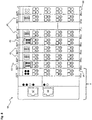
- Fig. 7 shows a composite 64 with an overcurrent protection terminal 43 and a plurality of signal terminals 45.
- the overcurrent protection terminal 43 is electrically and data-technically connected to a signal terminal 45 via the power contacts or contact structures described in detail above, the contact pins and the spring contacts.
- a plurality of further signal terminals 45 are also attached to the signal terminal 45 connected to the overcurrent protection terminal 43 via power contacts or contact structures, contact pins and spring contacts.
- the plurality of signal terminals 45 is designed to control a plurality of consumers.
- the overcurrent protection terminal 43 is connected to the higher-level fieldbus participant 8.
- the higher-level field bus subscriber 8 has an initial terminal 65.
- the starting terminal 65 has first to sixth spring contacts on its side surface facing the overcurrent protection terminal 43, as were described in relation to FIG.
- the communication channel 14, 141, 142 and a field bus energy channel of the field bus can thus be formed between the initial terminal 65 and the overcurrent protection terminal 43.
- the start terminal 65 is designed, for example, to supply the higher-level field bus subscriber 8 with electrical energy.
- the higher-level field bus subscriber 8 has two slots 66, 67 for field bus cables.
- the field bus cables can be cables with RJ-45 plugs, for example.
- a slot 66 can be provided for the communication channel 14, 141, 142, for example, while a further slot 67 can be provided for a further communication channel.
- the fieldbus cables can be connected to a control computer.
- the assembly 64 of the clamps terminates with an end clamp 68.
- the end terminal 68 is designed, for example, to lead back the communication channel 14, 141, 142 as a further communication channel.
- the end terminal 68 can also be dispensed with, provided that the last bus terminal is designed accordingly in the network to lead back the communication channel 14, 141, 142 as a further communication channel.
- the composite 64 could terminate terminals with a protective cap for possibly exposed contact structures.
- Fig. 8 shows a further composite 69 with two overcurrent protection terminals 43 and a plurality of signal terminals 45.
- the further composite 69 shown has a further overcurrent protection terminal 43, which is designed like the overcurrent protection terminal 43.
- Two signal terminals 45 are arranged in a row between the overcurrent protection terminal 43 and the further overcurrent protection terminal 43.
- the further overcurrent protection terminal 43 may be required if the loads connected to the field bus system 7 via the two signal terminals 45 arranged between the overcurrent protection terminals 43 consume a maximum available secured supply energy. In this case, it is advisable to arrange the further overcurrent protection terminal 43 in the group 69, because in this way further supply energy can be fed in and secured, which can be passed on to additional consumers as secured supply energy.
- the overcurrent protection terminal 43 It is also possible to switch on both overcurrent protection terminals 43 with a time delay. There are two ways to do this.
- the first possibility of a time-delayed switching on of the overcurrent protection terminals 43 is that the overcurrent protection terminal 43 generates a random number between 0 and 49 when the supply energy is applied. The result is then used to switch on the first supply output of the overcurrent protection terminal 43. For example, if the result is 10, the first supply output is switched on 10 ms late.
- the second supply output of the overcurrent protection terminal 43 is now always 50ms after switching on the first supply output switched on.
- the further overcurrent protection terminal 43 will generate a further random number, which usually differs from the random number, so that the first supply output of the further overcurrent protection terminal 43 can be switched on with a time delay to the first supply output of the overcurrent protection terminal 43, the second supply output of the further overcurrent protection terminal 43 again after 50 ms the further overcurrent protection terminal 43 is switched on when the first supply output is switched on.
- the second possibility of a time-delayed switching on of the overcurrent protection terminals 43 is that two different overcurrent protection terminals 43 stored in the control units 20 and unique for the respective control unit 20 are used to generate a number between 0 and 49. For example, it is a 96-bit wide unique identification number. The numbers generated are used as the switch-on time in ms for switching on the first supply outputs of the overcurrent protection terminals 43. The second supply outputs are always switched on 50 ms after the respective first supply outputs have been switched on.
- the advantage of this method is that an overcurrent protection terminal 43 always generates the same number, so that a possible switch-on problem can be reproduced well, which can simplify troubleshooting.
- serially connected switching elements can be formed between a supply input 80 and a supply output 81, 82.
- Each serially connected switching element can, for example, be activated independently of the control unit 20. This advantageously makes it possible to secure the first supply output 81 and / or the second supply output 82 redundantly.
- serially connected detection devices can be formed between a supply input 80 and a supply output 81, 82.
- Each serially connected detection device is designed, for example, to detect a parameter of the supply energy and / or a parameter of the secured supply energy. This advantageously makes it possible to monitor a parameter of the supply energy and / or a parameter of the secured supply energy in a multi-channel manner by the control unit 20 of the security module 9, 33, 37.
- the control unit 20 of the security module 9, 33, 37 can be parameterized via a field bus 11.
- a characteristic curve of the fuse module 9, 33, 37 describing the shutdown behavior can be set and / or changed via the fieldbus 11.
- the parameterization can take place, for example, via a programmable logic controller connected to the fieldbus 11. This advantageously enables simple commissioning.
- a fuse module 9, 33, 37 At least several characteristic curves describing the shutdown behavior of a fuse module 9, 33, 37 are stored in a fuse module 9, 33, 37 as standard or at the factory, the characteristic curves differing from one another and thus a user can set a desired shutdown behavior of the fuse module 9, 33, 37 by means of the standard characteristic curves without spending a great deal of time.
- a characteristic curve describing the shutdown behavior of a fuse module 9, 33, 37 can be set using the buttons 38, 39 or a fieldbus 11, for example.
- the first supply output 81 and / or the second supply output 82 are by means of a Reverse polarity protection protected. It is thus possible for the components of the fuse module 9, 33, 37 to be protected against incorrect connection of a consumer and the electrical currents that arise as a result.
- the first supply output 81 and / or the second supply output 82 has a feedback protection device.
- the feedback protection device prevents an electrical current from flowing from the first supply output 81 and / or the second supply output 82 to the supply input 80. Further electrical devices which are electrically connected to the supply input 80 are thus protected. It is also possible for the feedback protection device to be implemented in the first detection device 21 and / or in the first switching element 19 and / or in the second detection device 36 and / or in the second switching element 34.
- the information relating to the fuse protection of the first supply output 81 or the second supply output 82 in particular an electrical voltage detected by the first detection device 21 or by the second detection unit 36, a detected electrical current, a detected temporal development of the electrical voltage or the electrical current, a time period monitored by the control unit 20, within which the first switching element 19 or the second switching element 34 limits an electrical current, are stored in a memory unit integrated in the control unit 20.
- a time stamp can be added to the information relating to the protection of the first supply output 81 or the second supply output 82 when it is stored. This advantageously enables more precise status monitoring by means of a programmable logic controller connected to the fieldbus 11.
- the security module 9, 33, 37 has a pre-warning function. If, for example, an electrical current detected by the first or second detection device 21, 36 exceeds a previously determined percentage value of a set nominal current, this excess is visualized as part of the pre-warning function by means of a visual signal. This event, the exceeding, can also be transmitted to the field bus subscriber 8 as information relating to the protection of the first supply output 81 or the second supply output 82.
- the information relating to the protection of the first supply output 81 or the second supply output 82 in particular a predetermined value range of an electrical voltage, an electrical current, a temporal development of the electrical voltage or the electrical current or a period of time within which the first switching element 19 or the second switching element 34 limits an electrical current, stored in another field bus subscriber 8.
- the other field bus subscriber 8 can in particular be a programmable logic controller which, for example, controls a machine in an application-specific manner.
- the information relating to the protection of the first supply output 81 or the second supply output 82 can be transmitted from the programmable logic controller to an exchanged fuse module 9, 33, 37 by means of the fieldbus 11. This advantageously enables the previously set value ranges to be restored relatively quickly.
- the information relating to the protection of the first supply output 81 or the second supply output 82 can be stored in the control unit 20 in a password-protected manner.
- the password-protected information is preferably stored in encrypted form.
- the password protection advantageously protects the information relating to the protection of the first supply output 81 or the second supply output 82 from being changed by unauthorized persons.
- buttons 38, 39 connected to the control unit 20 can be deactivated or activated. If the buttons 38, 39 connected to the control unit 20 are deactivated, an unintentional change in the settings of the security module 9, 33, 37 can advantageously be prevented.
- the control unit 20 automatically controls the first switching element 19 or the second switching element 34 in order to electrically connect the supply input 80 to the first supply output 81 or the second supply output 82 at regular time intervals. After each electrical connection of the supply input 80 to the first supply output 81 or the second supply output 82, the control unit 20 monitors by means of the first detection device 21 or the second detection device 36 a parameter of the supply energy and / or a parameter of the secured supply energy.
- control unit 20 activates the first switching element 19 or the second switching element 34 again to electrically switch the supply input 80 from the first supply output 81 or the second supply output 82 to separate. Automatic repair with the aid of the safety module 9, 33, 37 is thus advantageously possible.
- the consumer 3 connected to the first supply output 81 and connected to the field bus system 7 by means of the signal module 10 or the further consumer 35 connected to the second supply output 82 can be an actuator, such as a Valve or electric motor, in particular a direct current motor, a sensor such as a pressure sensor or a temperature sensor, a fieldbus coupler, an electrical line and / or another capacitive or inductive load known in industrial automation technology.
- an actuator such as a Valve or electric motor, in particular a direct current motor, a sensor such as a pressure sensor or a temperature sensor, a fieldbus coupler, an electrical line and / or another capacitive or inductive load known in industrial automation technology.
Landscapes
- Engineering & Computer Science (AREA)
- Computer Networks & Wireless Communication (AREA)
- Signal Processing (AREA)
- Emergency Protection Circuit Devices (AREA)
- Direct Current Feeding And Distribution (AREA)
- Remote Monitoring And Control Of Power-Distribution Networks (AREA)
Description
Die vorliegende Erfindung betrifft ein Sicherungsmodul und ein Feldbussystem mit einem Sicherungsmodul.The present invention relates to a security module and a field bus system with a security module.
Diese Patentanmeldung beansprucht die Priorität der deutschen Patentanmeldung
Aus der Offenlegungsschrift
Ein Nachteil der in der
Aus
Die Aufgabe der vorliegenden Erfindung besteht darin, ein verbessertes Sicherungsmodul und ein Feldbussystem mit einem verbesserten Sicherungsmodul bereitzustellen.The object of the present invention is to provide an improved security module and a field bus system with an improved security module.
Diese Aufgaben werden durch ein Sicherungsmodul mit den Merkmalen des Anspruchs 1 und durch ein Feldbussystem mit einem Sicherungsmodul mit den Merkmalen des Anspruchs 13 gelöst. In den abhängigen Ansprüchen sind vorteilhafte Weiterbildungen angegeben.These objects are achieved by a security module with the features of claim 1 and by a field bus system with a security module with the features of
Ein Sicherungsmodul, welches allgemein auch als Schutzvorrichtung oder Überstromschutzmodul bezeichnet werden kann, für ein Feldbussystem weist eine Anschalteinheit, eine Steuereinheit, einen zum Einspeisen einer Versorgungsenergie in das Sicherungsmodul ausgebildeten Versorgungseingang, einen zum Weiterleiten der Versorgungsenergie als eine abgesicherte Versorgungsenergie an einen Verbraucher ausgebildeten ersten Versorgungsausgang, ein zum elektrischen Verbinden oder zum elektrischen Trennen des Versorgungseingangs und des ersten Versorgungsausgangs ausgebildetes erstes Schaltelement und ein zur Bereitstellung einer Betriebsenergie über eine Betriebsenergieversorgungsleitung für einen Betrieb der Steuereinheit ausgebildetes Versorgungsmodul auf. Das Versorgungsmodul ist mittels einer Versorgungsleitung und einer Versorgungsanbindungsleitung mit dem Versorgungseingang und mittels einer Feldbusenergieleitung und einer Feldbusenergieanbindungsleitung mit einem Feldbusenergieeingang elektrisch verbunden. Der Feldbusenergieeingang ist zum Einspeisen einer Feldbusenergie in das Sicherungsmodul zum Betrieb der Anschalteinheit ausgebildet. Das Versorgungsmodul ist dazu ausgebildet, die Betriebsenergie entweder aus der Versorgungsenergie oder aus der Feldbusenergie zu generieren. Die Anschalteinheit ist über eine Datenleitung mit der Steuereinheit verbunden und zur Anbindung des Sicherungsmoduls an einen Feldbusteilnehmer mittels eines Feldbusses ausgebildet, wodurch ein Austausch von Feldbusdaten zwischen der Steuereinheit und dem Feldbusteilnehmer ermöglicht wird. Die Steuereinheit ist mit dem ersten Schaltelement verbunden und dazu ausgebildet, das Weiterleiten der Versorgungsenergie als abgesicherte Versorgungsenergie über den ersten Versorgungsausgang durch ein Ansteuern des ersten Schaltelements abzusichern.A fuse module, which can generally also be referred to as a protection device or overcurrent protection module, for a field bus system has an interface unit, a control unit, a supply input designed to feed a supply energy into the fuse module, and a first supply output designed to forward the supply energy as a secured supply energy to a consumer , a first switching element designed to electrically connect or electrically separate the supply input and the first supply output and a supply module designed to provide operating energy via an operating energy supply line for operating the control unit. The supply module is electrically connected to the supply input by means of a supply line and a supply connection line and to a fieldbus energy input by means of a fieldbus energy line and a fieldbus energy connection line. The fieldbus energy input is designed to feed fieldbus energy into the fuse module for operating the connection unit. The supply module is designed to take the operating energy either from the supply energy or to generate from the fieldbus energy. The connection unit is connected to the control unit via a data line and is designed to connect the security module to a fieldbus participant by means of a fieldbus, which enables fieldbus data to be exchanged between the control unit and the fieldbus participant. The control unit is connected to the first switching element and is designed to safeguard the forwarding of the supply energy as secured supply energy via the first supply output by activating the first switching element.
Vorteilhafterweise ermöglicht es das Versorgungsmodul, dass der Steuereinheit die Betriebsenergie bereitgestellt werden kann, falls entweder die Versorgungsenergie oder die Feldbusenergie ausfällt oder die Versorgungsenergie oder die Feldbusenergie außerhalb eines vorgegebenen Versorgungsenergiewertebereichs oder außerhalb eines vorgegebenen Feldbusenergiewertebereichs liegt, sodass die Erzeugung der Betriebsenergie nicht möglich ist. Das Versorgungsmodul ist mittels einer Betriebsenergieleitung elektrisch mit der Steuereinheit verbunden, um die Steuereinheit mit der generierten Betriebsenergie zu versorgen.The supply module advantageously enables the control unit to be provided with the operating energy if either the supply energy or the fieldbus energy fails or the supply energy or the fieldbus energy is outside a specified supply energy range or outside a specified fieldbus energy range, so that the generation of the operating energy is not possible. The supply module is electrically connected to the control unit by means of an operating energy line in order to supply the control unit with the generated operating energy.
Vorteilhafterweise ist das Sicherungsmodul auch dazu ausgebildet, den Verbraucher beispielsweise vor einem zu hohen elektrischen Strom abzusichern. Ein weiterer Vorteil besteht darin, dass das Sicherungsmodul mittels des Feldbusses mit einem Feldbusteilnehmer des Feldbussystems verbunden werden kann. Der Feldbusteilnehmer kann als Steuerung des Feldbussystems ausgebildet sein. Auch kann es sich bei dem Feldbusteilnehmer um einen Master bzw. Feldbusmaster des Feldbussystems handeln. Ebenso kann der Feldbusteilnehmer ein oder eine Mehrzahl beliebiger anderer Teilnehmer, wie beispielsweise Feldbuskoppler und/oder Feldbusklemmen, welche auch als Busklemmen bezeichnet werden können, im Feldbussystem sein. Das Sicherungsmodul kann somit selber ein Feldbusteilnehmer sein und dadurch wie ein gewöhnlicher Teilnehmer des Feldbussystems angesprochen werden. Eine externe Verkabelung zum Anschluss des Sicherungsmoduls an das Feldbussystem entfällt damit. Ein weiterer Vorteil besteht darin, dass das Sicherungsmodul bei Anlegen der Versorgungsenergie schon eine Absicherungsfunktion erfüllt, auch wenn der Feldbus unterbrochen oder noch nicht betriebsbereit ist.The fuse module is advantageously also designed to protect the consumer, for example, from an excessively high electrical current. Another advantage is that the security module can be connected to a field bus participant of the field bus system by means of the field bus. The field bus participant can be designed as a controller for the field bus system. The field bus participant can also be a master or field bus master of the field bus system. Likewise, the field bus subscriber can be one or a plurality of any other subscribers, such as, for example, field bus couplers and / or field bus terminals, which can also be referred to as bus terminals, in the field bus system. The security module can thus itself be a field bus participant and can thus be addressed like a normal subscriber in the fieldbus system. External cabling to connect the fuse module to the field bus system is therefore no longer necessary. Another advantage is that the safety module already fulfills a safety function when the supply energy is applied, even if the fieldbus is interrupted or not yet ready for operation.
In einer Ausführungsform ist das Versorgungsmodul dazu ausgebildet, die Betriebsenergie aus der Feldbusenergie zu generieren, falls die Versorgungsenergie außerhalb eines vorgegebenen Versorgungsenergiewertebereichs liegt. Vorteilhafterweise wird der Feldbus nicht gestört oder unterbrochen, wenn die Versorgungsenergie nicht zur Bereitstellung der Betriebsenergie für die Steuereinheit verwendet werden kann. Zwar ist beispielsweise eine Überstromschutzfunktion des Sicherungsmoduls nicht gegeben, wenn die Versorgungsenergie außerhalb des vorgegebenen Versorgungsenergiewertebereichs liegt. Dennoch muss die Steuereinheit weiterhin mit der aus der Feldbusenergie generierten Betriebsenergie versorgt werden, damit die Anschalteinheit weiterhin Feldbusdaten von der Steuereinheit empfangen kann. Auf diese Weise ist sichergestellt, dass der Feldbus nicht gestört oder unterbrochen wird. Es ist jedoch auch möglich, dass das Versorgungsmodul dazu ausgebildet ist, die Betriebsenergie aus der Versorgungsenergie zu generieren, falls die Feldbusenergie außerhalb eines vorgegebenen Versorgungsenergiewertebereichs liegt. In diesem Fall wird also die Feldbusenergie primär zur Generierung der Betriebsenergie verwendet, während die Versorgungsenergie als Alternative zur Generierung der Betriebsenergie verwendet werden kann.In one embodiment, the supply module is designed to generate the operating energy from the fieldbus energy if the supply energy lies outside a predetermined supply energy value range. The field bus is advantageously not disturbed or interrupted if the supply energy cannot be used to provide the operating energy for the control unit. For example, the fuse module does not have an overcurrent protection function if the supply energy is outside the specified supply energy value range. Nevertheless, the control unit must still be supplied with the operating energy generated from the fieldbus energy so that the interface unit can continue to receive fieldbus data from the control unit. This ensures that the fieldbus is not disturbed or interrupted. However, it is also possible that the supply module is designed to generate the operating energy from the supply energy if the fieldbus energy lies outside a predetermined supply energy value range. In this case, the fieldbus energy is primarily used to generate the operating energy, while the supply energy can be used as an alternative to generating the operating energy.
In einer Ausführungsform ist die Steuereinheit dazu ausgebildet, im Rahmen der Absicherung des ersten Versorgungsausgangs einen Parameter der Versorgungsenergie und/oder einen Parameter der abgesicherten Versorgungsenergie mittels einer mit der Steuereinheit verbundenen ersten Erfassungseinrichtung zu überwachen. Die Steuereinheit ist dazu ausgebildet, den Versorgungseingang und den ersten Versorgungsausgang im Rahmen der Absicherung mittels des ersten Schaltelements elektrisch voneinander zu trennen, sobald der überwachte Parameter außerhalb eines vorgegebenen Wertebereichs liegt.In one embodiment, the control unit is designed to supply a parameter of the supply energy and / or a parameter of the protected supply energy by means of a first detection device connected to the control unit as part of the protection of the first supply output monitor. The control unit is designed to electrically isolate the supply input and the first supply output from one another as part of the safeguarding by means of the first switching element as soon as the monitored parameter is outside a predetermined value range.
Vorteilhafterweise wird der Verbraucher durch das elektrische Trennen des Versorgungseingangs und des ersten Versorgungsausgangs abgesichert, wenn der überwachte Parameter außerhalb eines vorgegebenen Wertebereichs liegt. Der Parameter der Versorgungsenergie und/oder der Parameter der abgesicherten Versorgungsenergie kann beispielsweise ein elektrischer Strom, eine elektrische Spannung, eine zeitlichen Entwicklung des elektrischen Stroms oder der elektrischen Spannung oder eine Zeitdauer, innerhalb derer ein elektrischer Strom begrenzt werden soll, sein. Beispielsweise kann der Parameter der Versorgungsenergie und/oder der Parameter der abgesicherten Versorgungsenergie auch eine Kombination aus dem elektrischen Strom mit der elektrischen Spannung und/oder eine Kombination aus einer zeitlichen Entwicklung des elektrischen Stroms und der elektrischen Spannung und/oder eine Kombination aus einem elektrischen Strom mit einer Zeitdauer, innerhalb derer ein elektrischer Strom begrenzt werden soll, und/oder eine Kombination aus einer elektrischen Spannung mit einer Zeitdauer, innerhalb derer ein elektrischer Strom begrenzt werden soll, sein.The consumer is advantageously protected by electrically isolating the supply input and the first supply output if the monitored parameter is outside a predetermined value range. The parameter of the supply energy and / or the parameter of the secured supply energy can for example be an electrical current, an electrical voltage, a temporal development of the electrical current or the electrical voltage or a period of time within which an electrical current is to be limited. For example, the parameter of the supply energy and / or the parameter of the secured supply energy can also be a combination of the electrical current with the electrical voltage and / or a combination of a temporal development of the electrical current and the electrical voltage and / or a combination of an electrical current with a period of time within which an electrical current is to be limited and / or a combination of an electrical voltage with a period of time within which an electrical current is to be limited.
In einer Ausführungsform ist die Steuereinheit dazu ausgebildet, eine die Absicherung des ersten Versorgungsausgangs betreffende Information mittels der Feldbusdaten über die Anschalteinheit mit dem Feldbusteilnehmer auszutauschen.In one embodiment, the control unit is designed to exchange information relating to the protection of the first supply output by means of the field bus data via the connection unit with the field bus subscriber.
In einer Ausführungsform ist die Steuereinheit dazu ausgebildet ist, die die Absicherung betreffende Information an den Feldbusteilnehmer zu übermitteln. Die die Absicherung des ersten Versorgungsausgangs betreffende Information ist eine von der ersten Erfassungseinrichtung erfasste elektrische Spannung, ein erfasster elektrischer Strom, eine erfasste zeitliche Entwicklung der elektrischen Spannung oder des elektrischen Stroms, ein erfasster Schaltzustand des ersten Schaltelements oder eine von der Steuereinheit überwachte Zeitdauer, innerhalb derer das erste Schaltelement einen elektrischen Strom begrenzt. Vorteilhafterweise kann dadurch eine Zustandsüberwachung des Sicherungsmoduls erfolgen.In one embodiment, the control unit is designed to transmit the information relating to the protection to the field bus subscriber. The information relating to the protection of the first supply output is an electrical voltage, a detected electrical current, a detected one by the first detection device Temporal development of the electrical voltage or the electrical current, a detected switching state of the first switching element or a period of time monitored by the control unit, within which the first switching element limits an electrical current. In this way, the status of the security module can advantageously be monitored.
In einer Ausführungsform ist die Steuereinheit dazu ausgebildet, die die Absicherung betreffende Information von dem Feldbusteilnehmer zu empfangen. Die die Absicherung des ersten Versorgungsausgangs betreffende Information ist ein vorgegebener Wertebereich einer elektrischen Spannung, eines elektrischen Stroms, einer zeitlichen Entwicklung der elektrischen Spannung oder des elektrischen Stroms oder einer Zeitdauer, innerhalb derer das erste Schaltelement einen elektrischen Strom begrenzt. Vorteilhafterweise kann die Steuereinheit die die Absicherung betreffende Information verwenden, um den ersten Versorgungsausgang abzusichern.In one embodiment, the control unit is designed to receive the information relating to the protection from the field bus participant. The information relating to the protection of the first supply output is a predefined range of values for an electrical voltage, an electrical current, a temporal development of the electrical voltage or the electrical current, or a period of time within which the first switching element limits an electrical current. The control unit can advantageously use the information relating to the protection in order to protect the first supply output.
In einer Ausführungsform weist das Sicherungsmodul eine erste Isolationsvorrichtung auf. Die erste Isolationsvorrichtung ist in der Feldbusenergieanbindungsleitung geschaltet. Dadurch weist die Feldbusenergieanbindungsleitung einen ersten Abschnitt und einen zweiten Abschnitt auf. Die erste Isolationsvorrichtung ist dazu ausgebildet, den ersten Abschnitt und den zweiten Abschnitt der Feldbusenergieanbindungsleitung galvanisch voneinander zu trennen.In one embodiment, the fuse module has a first insulation device. The first isolation device is connected in the fieldbus power connection line. As a result, the fieldbus power connection line has a first section and a second section. The first isolation device is designed to galvanically separate the first section and the second section of the fieldbus energy connection line from one another.
In einer Ausführungsform weist das Sicherungsmodul eine zweite Isolationsvorrichtung auf. Die zweite Isolationsvorrichtung ist in der Datenleitung geschaltet. Dadurch weist die Datenleitung einen ersten Abschnitt und einen zweiten Abschnitt auf. Die zweite Isolationsvorrichtung ist dazu ausgebildet, den ersten Abschnitt und den zweiten Abschnitt der Datenleitung galvanisch voneinander zu trennen. Vorteilhafterweise sind durch eine galvanische Trennung des ersten und des zweiten Abschnitts der Feldbusenergieanbindungsleitung und durch eine galvanische Trennung des ersten und des zweiten Abschnitts der Datenleitung die Versorgungsleitung und die Feldbusenergieleitung galvanisch voneinander getrennt. Somit wird die Energieversorgung galvanisch getrennt. Dadurch kann eine Übertragung von Störsignalen zwischen der Versorgungsenergieleitung und der Feldbusenergieleitung vermieden werden. Insbesondere ist dadurch auch die Feldbusenergieleitung von der Betriebsenergieleitung galvanisch getrennt, wodurch eine Übertragung von Störsignalen zwischen der Feldbusenergieleitung und der Betriebsenergieleitung vermieden werden kann. Ebenfalls galvanisch voneinander getrennt sind die Versorgungsenergieleitung und ein Kommunikationskanal des Feldbusses. Damit kann auch eine Übertragung von Störsignalen zwischen der Versorgungsenergieleitung und dem Kommunikationskanal, über den ein Austausch von Feldbusdaten erfolgen kann, vermieden werden. Insgesamt sind also die Versorgungsenergieleitung und der Feldbus galvanisch voneinander getrennt.In one embodiment, the fuse module has a second insulation device. The second isolation device is connected in the data line. As a result, the data line has a first section and a second section. The second isolation device is designed to galvanically separate the first section and the second section of the data line from one another. The supply line and the fieldbus energy line are advantageously galvanically separated from one another by galvanic separation of the first and second sections of the fieldbus energy connection line and galvanic separation of the first and second sections of the data line. The energy supply is thus galvanically separated. This avoids the transmission of interference signals between the power supply line and the fieldbus power line. In particular, the fieldbus power line is thereby also galvanically separated from the operating power line, as a result of which a transmission of interference signals between the fieldbus power line and the operating power line can be avoided. The power supply line and a communication channel of the fieldbus are also galvanically separated from each other. This also avoids the transmission of interference signals between the power supply line and the communication channel, via which fieldbus data can be exchanged. Overall, the power supply line and the fieldbus are galvanically isolated from one another.
In einer Ausführungsform weist das Sicherungsmodul einen zum Weiterleiten der abgesicherten Versorgungsenergie an einen weiteren Verbraucher ausgebildeten zweiten Versorgungsausgang und ein zum elektrischen Verbinden oder zum elektrischen Trennen des Versorgungseingangs und des zweiten Versorgungsausgangs ausgebildetes zweites Schaltelement auf. Das zweite Schaltelement ist mit der Steuereinheit verbunden. Das erste Schaltelement und das zweite Schaltelement sind unabhängig voneinander von der Steuereinheit ansteuerbar. Die Steuereinheit ist dazu ausgebildet, das Weiterleiten der Versorgungsenergie als abgesicherte Versorgungsenergie über den zweiten Versorgungsausgang durch ein Ansteuern des zweiten Schaltelements abzusichern. Die Steuereinheit ist dazu ausgebildet, im Rahmen der Absicherung des zweiten Versorgungsausgangs einen weiteren Parameter der Versorgungsenergie und/oder einen weiteren Parameter der abgesicherten Versorgungsenergie mittels einer mit der Steuereinheit verbundenen zweiten Erfassungseinrichtung zu überwachen. Die Steuereinheit ist dazu ausgebildet, den Versorgungseingang und den zweiten Versorgungsausgang im Rahmen der Absicherung mittels des zweiten Schaltelements elektrisch voneinander zu trennen, sobald der weitere überwachte Parameter außerhalb eines weiteren vorgegebenen Wertebereichs liegt. Die Steuereinheit ist dazu ausgebildet, eine die Absicherung des zweiten Versorgungsausgangs betreffende Information mittels der Feldbusdaten über die Anschalteinheit mit dem Feldbusteilnehmer auszutauschen. Vorteilhafterweise ist das das zweite Schaltelement aufweisende Sicherungsmodul dazu ausgebildet, einen weiteren Verbraucher beispielsweise vor einem zu hohen elektrischen Strom abzusichern.In one embodiment, the fuse module has a second supply output configured to forward the protected supply energy to a further consumer and a second switching element configured to electrically connect or disconnect the supply input and the second supply output. The second switching element is connected to the control unit. The first switching element and the second switching element can be controlled independently of one another by the control unit. The control unit is designed to safeguard the forwarding of the supply energy as secured supply energy via the second supply output by activating the second switching element. The control unit is designed to use a further parameter of the supply energy and / or a further parameter of the protected supply energy within the scope of protecting the second supply output a second detection device connected to the control unit. The control unit is designed to electrically isolate the supply input and the second supply output from one another as part of the safeguarding by means of the second switching element as soon as the further monitored parameter is outside a further predetermined value range. The control unit is designed to exchange information relating to the protection of the second supply output by means of the field bus data via the connection unit with the field bus subscriber. The fuse module having the second switching element is advantageously designed to protect a further consumer, for example, from an electrical current that is too high.
Der weitere Parameter der Versorgungsenergie und/oder der weiterer Parameter der abgesicherten Versorgungsenergie kann beispielsweise ein elektrischer Strom, eine elektrische Spannung, eine zeitlichen Entwicklung des elektrischen Stroms oder der elektrischen Spannung oder eine Zeitdauer, innerhalb derer ein elektrischer Strom begrenzt werden soll, sein. Beispielsweise kann der weitere Parameter der Versorgungsenergie und/oder der weitere Parameter der abgesicherten Versorgungsenergie auch eine Kombination aus dem elektrischen Strom mit der elektrischen Spannung und/oder eine Kombination aus einer zeitlichen Entwicklung des elektrischen Stroms und der elektrischen Spannung und/oder eine Kombination aus einem elektrischen Strom mit einer Zeitdauer, innerhalb derer ein elektrischer Strom begrenzt werden soll, und/oder eine Kombination aus einer elektrischen Spannung mit einer Zeitdauer, innerhalb derer ein elektrischer Strom begrenzt werden soll, sein.The further parameter of the supply energy and / or the further parameter of the secured supply energy can be, for example, an electrical current, an electrical voltage, a temporal development of the electrical current or the electrical voltage or a period of time within which an electrical current is to be limited. For example, the further parameter of the supply energy and / or the further parameter of the secured supply energy can also be a combination of the electrical current with the electrical voltage and / or a combination of a temporal development of the electrical current and the electrical voltage and / or a combination of a electrical current with a period of time within which an electrical current is to be limited and / or a combination of an electrical voltage with a period of time within which an electrical current is to be limited.
Die Steuereinheit kann beispielsweise dazu ausgebildet sein, die die Absicherung des zweiten Versorgungsausgangs betreffende Information an den Feldbusteilnehmer zu übermitteln. Die die Absicherung des zweiten Versorgungsausgangs betreffende Information kann eine von der zweiten Erfassungseinrichtung erfasste elektrische Spannung, ein erfasster elektrischer Strom, eine erfasste zeitliche Entwicklung der elektrischen Spannung oder des elektrischen Stroms, ein erfasster Schaltzustand des zweiten Schaltelements oder eine von der Steuereinheit überwachte Zeitdauer, innerhalb derer das zweite Schaltelement einen elektrischen Strom begrenzt, sein.The control unit can be designed, for example, to transmit the information relating to the protection of the second supply output to the field bus subscriber. The one relating to the protection of the second supply outlet Information can be an electrical voltage detected by the second detection device, a detected electric current, a detected temporal development of the electrical voltage or the electric current, a detected switching state of the second switching element or a period of time monitored by the control unit within which the second switching element supplies an electrical current limited, be.
Die Steuereinheit kann auch dazu ausgebildet, die die Absicherung des zweiten Versorgungsausgangs betreffende Information von dem Feldbusteilnehmer zu empfangen. Die die Absicherung des zweiten Versorgungsausgangs betreffende Information kann ein vorgegebener Wertebereich einer elektrischen Spannung, eines elektrischen Stroms, einer zeitlichen Entwicklung der elektrischen Spannung oder des elektrischen Stroms oder einer Zeitdauer, innerhalb derer das zweite Schaltelement einen elektrischen Strom begrenzt, sein. Vorteilhafterweise kann die Steuereinheit die die Absicherung des zweiten Versorgungsausgangs betreffende Information verwenden, um den zweiten Versorgungsausgang abzusichern.The control unit can also be designed to receive the information relating to the protection of the second supply output from the field bus user. The information relating to the securing of the second supply output can be a predetermined value range of an electrical voltage, an electrical current, a temporal development of the electrical voltage or the electrical current or a period of time within which the second switching element limits an electrical current. The control unit can advantageously use the information relating to the protection of the second supply output in order to protect the second supply output.
In einer Ausführungsform sind die Anschalteinheit, die Steuereinheit, das erste Schaltelement und das Versorgungsmodul in einem gemeinsamen Gehäuse angeordnet sind. Vorteilhafterweise ist das Sicherungsmodul dadurch kompakt und kann als eine Busklemme in einen Busklemmenverbund angereiht werden.In one embodiment, the connection unit, the control unit, the first switching element and the supply module are arranged in a common housing. As a result, the fuse module is advantageously compact and can be lined up as a bus terminal in a bus terminal network.
In einer Ausführungsform weist das Gehäuse eine Seitenfläche auf. Die Seitenfläche ist dazu ausgebildet, unmittelbar an einer weiteren Seitenfläche eines weiteren Gehäuses eines zur Anbindung des Verbrauchers an das Feldbussystem ausgebildeten Signalmoduls anzuliegen. Der erste Versorgungsausgang ist an der Seitenfläche als Kontaktstruktur ausgebildet. Die Kontaktstruktur ist dazu ausgebildet, zur Weiterleitung der abgesicherten Versorgungsenergie unmittelbar an einem an der weiteren Seitenfläche als weitere Kontaktstruktur ausgebildeten weiteren Versorgungseingang des Signalmoduls anzuliegen und die weitere Kontaktstruktur elektrisch zu kontaktieren, wodurch das Sicherungsmodul unmittelbar an das Signalmodul anreihbar ist. Vorteilhafterweise kann die abgesicherte Versorgungsenergie über die Kontaktstrukturen weitergeleitet werden, ohne dass eine zusätzliche Verkabelung notwendig ist.In one embodiment, the housing has a side surface. The side surface is designed to lie directly against a further side surface of a further housing of a signal module designed to connect the consumer to the field bus system. The first supply outlet is designed as a contact structure on the side surface. The contact structure is designed to be in direct contact with a further supply input of the signal module, which is designed as a further contact structure on the further side surface, in order to pass on the secured supply energy and to make electrical contact with the further contact structure, as a result of which the fuse module can be directly aligned with the signal module. The secured supply energy can advantageously be passed on via the contact structures without the need for additional cabling.
In einer Ausführungsform weist das Gehäuse eine quer zur Seitenfläche ausgebildete Frontseite auf. Der zweite Versorgungsausgang ist zur Weiterleitung der abgesicherten Versorgungsenergie an den weiteren Verbraucher als ein von der Frontseite zur elektrischen Kontaktierung zugängliches Kontaktelement ausgebildet.In one embodiment, the housing has a front side formed transversely to the side surface. The second supply output is designed as a contact element accessible from the front for electrical contacting for forwarding the secured supply energy to the further consumer.
Ein Feldbussystem weist einen Feldbusteilnehmer, ein als weiterer Feldbusteilnehmer des Feldbussystems ausgebildetes Sicherungsmodul und ein als weiterer Feldbusteilnehmer des Feldbussystems ausgebildetes Signalmodul zum Anschluss eines Verbrauchers an das Feldbussystem auf. Der Feldbusteilnehmer, das Sicherungsmodul und das Signalmodul sind über einen Feldbus miteinander verbunden. Das Sicherungsmodul weist eine Anschalteinheit, eine Steuereinheit, einen zum Einspeisen einer Versorgungsenergie in das Sicherungsmodul ausgebildeten Versorgungseingang, einen zum Weiterleiten der Versorgungsenergie als abgesicherte Versorgungsenergie an den Verbraucher ausgebildeten ersten Versorgungsausgang und ein zum elektrischen Verbinden oder zum elektrischen Trennen des Versorgungseingangs und des ersten Versorgungsausgangs ausgebildetes erstes Schaltelement auf. Die Anschalteinheit ist über eine Datenleitung mit der Steuereinheit verbunden und zur Anbindung des Sicherungsmoduls an den Feldbusteilnehmer mittels des Feldbusses ausgebildet, wodurch ein Austausch von Feldbusdaten zwischen der Steuereinheit und dem Feldbusteilnehmer ermöglicht wird. Die Steuereinheit ist mit dem ersten Schaltelement verbunden und dazu ausgebildet, das Weiterleiten der Versorgungsenergie als abgesicherte Versorgungsenergie über den ersten Versorgungsausgang durch ein Ansteuern des ersten Schaltelements abzusichern. Das Signalmodul weist eine weitere Steuereinheit und eine weitere Anschalteinheit auf. Die weitere Anschalteinheit ist über eine weitere Datenleitung mit der weiteren Steuereinheit verbunden und zur Anbindung des Signalmoduls an den Feldbusteilnehmer mittels des Feldbusses ausgebildet, wodurch ein Austausch von Feldbusdaten zwischen der weiteren Steuereinheit und dem Feldbusteilnehmer ermöglicht wird. Die weitere Steuereinheit ist zur Anbindung des Verbrauchers an das Feldbussystem ausgebildet. Das Signalmodul weist einen zur Einspeisung der abgesicherten Versorgungsenergie ausgebildeten weiteren Versorgungseingang und einen zum Weiterleiten der abgesicherten Versorgungsenergie an den Verbraucher ausgebildeten weiteren Versorgungsausgang auf. Der erste Versorgungsausgang und der weitere Versorgungseingang sind elektrisch miteinander verbunden.A field bus system has a field bus participant, a security module designed as a further field bus participant of the field bus system and a signal module designed as a further field bus participant of the field bus system for connecting a consumer to the field bus system. The field bus participant, the security module and the signal module are connected to one another via a field bus. The fuse module has a connection unit, a control unit, a supply input designed to feed a supply energy into the fuse module, a first supply output designed to pass on the supply energy as secured supply energy to the consumer, and a first supply output designed to electrically connect or disconnect the supply input and the first supply output first switching element on. The connection unit is connected to the control unit via a data line and is designed to connect the security module to the field bus subscriber by means of the field bus, which enables fieldbus data to be exchanged between the control unit and the field bus subscriber. The control unit is connected to the first switching element and is designed to safeguard the forwarding of the supply energy as secured supply energy via the first supply output by activating the first switching element. The signal module has a further control unit and a further connection unit. The Another connection unit is connected to the further control unit via a further data line and is designed to connect the signal module to the fieldbus participant by means of the fieldbus, which enables fieldbus data to be exchanged between the further control unit and the fieldbus participant. The further control unit is designed to connect the consumer to the field bus system. The signal module has a further supply input designed to feed in the secured supply energy and a further supply output designed to forward the secured supply energy to the consumer. The first supply output and the further supply input are electrically connected to one another.
In einer Ausführungsform des Feldbussystems weist das Sicherungsmodul ein zur Bereitstellung einer Betriebsenergie über eine Betriebsenergieversorgungsleitung für einen Betrieb der Steuereinheit ausgebildetes Versorgungsmodul auf. Das Versorgungsmodul ist mittels einer Versorgungsleitung und einer Versorgungsanbindungsleitung mit dem Versorgungseingang und mittels einer Feldbusenergieleitung und einer Feldbusenergieanbindungsleitung mit einem Feldbusenergieeingang elektrisch verbunden. Der Feldbusenergieeingang ist zum Einspeisen einer Feldbusenergie in das Sicherungsmodul zum Betrieb der Anschalteinheit ausgebildet. Das Versorgungsmodul ist dazu ausgebildet, die Betriebsenergie entweder aus der Versorgungsenergie oder aus der Feldbusenergie zu generieren.In one embodiment of the field bus system, the security module has a supply module designed to provide operating energy via an operating energy supply line for operating the control unit. The supply module is electrically connected to the supply input by means of a supply line and a supply connection line and to a fieldbus energy input by means of a fieldbus energy line and a fieldbus energy connection line. The fieldbus energy input is designed to feed fieldbus energy into the fuse module for operating the connection unit. The supply module is designed to generate the operating energy either from the supply energy or from the fieldbus energy.
In einer Ausführungsform des Feldbussystems sind die Anschalteinheit, die Steuereinheit, das erste Schaltelement und das Versorgungsmodul in einem gemeinsamen Gehäuse angeordnet. Die weitere Anschalteinheit, die weitere Steuereinheit und ein weiteres Schaltelement zum Ansteuern des Verbrauchers mittels der weiteren Steuereinheit sind in einem weiteren Gehäuse angeordnet. Das Gehäuse weist eine Seitenfläche auf. Die Seitenfläche liegt unmittelbar an einer weiteren Seitenfläche des weiteren Gehäuses des Signalmoduls an. Der erste Versorgungsausgang ist an der Seitenfläche als Kontaktstruktur ausgebildet. Die Kontaktstruktur liegt, zur Weiterleitung der abgesicherten Versorgungsenergie unmittelbar an einem an der weiteren Seitenfläche als weitere Kontaktstruktur ausgebildeten weiteren Versorgungseingang des Signalmoduls an, wodurch das Sicherungsmodul unmittelbar an das Signalmodul angereiht ist.In one embodiment of the field bus system, the connection unit, the control unit, the first switching element and the supply module are arranged in a common housing. The further connection unit, the further control unit and a further switching element for controlling the consumer by means of the further control unit are arranged in a further housing. The housing has a side surface. The side surface rests directly on a further side surface of the further housing of the signal module. The first The supply outlet is designed as a contact structure on the side surface. In order to pass on the secured supply energy, the contact structure rests directly on a further supply input of the signal module which is designed as a further contact structure on the further side surface, whereby the fuse module is directly attached to the signal module.
Die oben beschriebenen Eigenschaften, Merkmale und Vorteile dieser Erfindung sowie die Art und Weise, wie diese erreicht werden, sind klarer und deutlicher verständlich im Zusammenhang mit der folgenden Beschreibung der Ausführungsbeispiele, die im Zusammenhang mit den Zeichnungen näher erläutert werden. Dabei zeigen in jeweils schematischer Darstellung:
-
Fig. 1 : ein Feldbussystem mit einem Sicherungsmodul gemäß einer ersten Ausführungsform; -
Fig. 2A : eine erste Ausführungsform eines Versorgungsmoduls des Sicherungsmoduls; -
Fig. 2B : eine zweite Ausführungsform eines Versorgungsmoduls des Sicherungsmoduls; -
Fig. 3 : ein Feldbussystem mit einem Sicherungsmodul gemäß einer zweiten Ausführungsform; -
Fig. 4 : ein Sicherungsmodul gemäß einer dritten Ausführungsform; -
Fig. 5 : eine Frontansicht eines als Busklemme ausgebildeten Sicherungsmoduls und eine Frontansicht eines als Busklemme ausgebildeten Signalmoduls; -
Fig. 6 : eine perspektivische Ansicht des als Busklemme ausgebildeten Sicherungsmoduls; -
Fig. 7 : einen Verbund mit einem Sicherungsmodul und einer Mehrzahl von Signalmodulen; -
Fig. 8 : einen Verbund mit zwei Sicherungsmodulen und einer Mehrzahl von Signalmodulen.
-
Fig. 1 : a field bus system with a security module according to a first embodiment; -
Figure 2A : a first embodiment of a supply module of the security module; -
Figure 2B : a second embodiment of a supply module of the security module; -
Fig. 3 : a field bus system with a security module according to a second embodiment; -
Fig. 4 : a security module according to a third embodiment; -
Fig. 5 : a front view of a fuse module designed as a bus terminal and a front view of a signal module designed as a bus terminal; -
Fig. 6 : a perspective view of the fuse module designed as a bus terminal; -
Fig. 7 : a network with a security module and a plurality of signal modules; -
Fig. 8 : a network with two fuse modules and a plurality of signal modules.
Das Feldbussystem 7 weist einen Feldbusteilnehmer 8, ein als Teilnehmer des Feldbussystems 7 ausgebildetes Sicherungsmodul 9 gemäß einer ersten Ausführungsform und ein als Teilnehmer des Feldbussystems 7 ausgebildetes Signalmodul 10 zum Anschluss eines Verbrauchers 3 an das Feldbussystem 7 auf.The
Der Feldbusteilnehmer 8 kann beispielsweise eine Steuerung mit integriertem Feldbusmaster sein. Der Feldbusteilnehmer 8 kann jedoch auch ein Feldbuskoppler sein. Der Feldbuskoppler kann wiederum seinerseits mit der Steuerung verbunden sein, sodass die Steuerung dem Feldbuskoppler übergeordnet ist. Insofern kann ein Feldbusteilnehmer 8 gemäß der vorstehenden Definition auch als ein übergeordneter Feldbusteilnehmer 8 bezeichnet werden. Selbstverständlich kann das Feldbussystem 7 auch weitere Feldbusteilnehmer 8 enthalten, denen beliebige Aufgaben innerhalb des Feldbussystems 7 zugeordnet sind. So können auch das Sicherungsmodul 9 und/oder das Signalmodul 10 Feldbusteilnehmer 8 im Sinne der Erfindung sein. Die folgende beispielhafte Beschreibung der Ausführungsbeispiele bezieht sich auf Feldbussysteme 7 mit einem übergeordneten Feldbusteilnehmer 8. Insofern wird im Folgendem von einem übergeordneten Feldbusteilnehmer 8 gesprochen. Dies ist jedoch nicht einschränkend im Sinne der Erfindung zu verstehen.The
Der übergeordnete Feldbusteilnehmer 8, das Sicherungsmodul 9 und das Signalmodul 10 sind über einen Feldbus 11 miteinander verbunden. Zur Anbindung an den Feldbus 11 weist das Sicherungsmodul 9 eine Anschalteinheit 12 und das Signalmodul 10 eine weitere Anschalteinheit 13 auf. Die Anschalteinheit 12 und die weitere Anschalteinheit 13 sind über den Feldbus 11 mit dem übergeordneten Feldbusteilnehmer 8 verbunden und dazu ausgebildet, Feldbusdaten zwischen dem übergeordneten Feldbusteilnehmer 8, dem Sicherungsmodul 9 und/oder dem Signalmodul 10 auszutauschen. Die Anschalteinheit 12 und/oder die weitere Anschalteinheit 13 können beispielsweise als ASIC (englisch: application-specific integrated circuits, anwendungsspezifische integrierte Schaltungen) ausgebildet sein. Die Anschalteinheit 12 und/oder die weitere Anschalteinheit 13 können auch als Fieldbus Slave Controller bezeichnet werden.The higher-level
Der Feldbus 11 weist einen Kommunikationskanal 14, 141, 142 auf. Der Kommunikationskanal 14, 141, 142 weist einen ersten Kommunikationskanalabschnitt 14, einen zweiten Kommunikationskanalabschnitt 141 und einen dritten Kommunikationskanalabschnitt 142 auf. Der Feldbus 11 weist weiterhin eine Feldbusenergieversorgungsleitung 95, eine Feldbusenergieleitung 15 und eine Feldbusleitung 99 auf. Der erste Kommunikationskanalabschnitt 14 und die Feldbusenergieleitung 15 sind innerhalb des Sicherungsmoduls 9 angeordnet. Der dritte Kommunikationskanalabschnitt 142 und die Feldbusleitung 99 sind innerhalb des Signalmoduls 10 angeordnet. Der zweite Kommunikationskanalabschnitt 141 und die Feldbusenergieversorgungsleitung 95 sind außerhalb des Sicherungsmoduls 9 und außerhalb des Signalmoduls 10 angeordnet. Der erste Kommunikationskanalabschnitt 14, der zweite Kommunikationskanalabschnitt 141 und der dritte Kommunikationskanalabschnitt 142 sind elektrisch miteinander verbunden. Die Feldbusenergieleitung 15, die Feldbusenergieversorgungsleitung 95 und die Feldbusleitung 99 sind ebenfalls elektrisch miteinander verbunden. Der erste Kommunikationskanalabschnitt 14 und der dritte Kommunikationskanalabschnitt 142 können beispielsweise mittels einer Verkabelung elektrisch miteinander verbunden sein. Auch die Feldbusenergieleitung 15 und die Feldbusleitung 99 können mittels einer Verkabelung elektrisch miteinander verbunden sein. Eine weitere Möglichkeit einer elektrischen Verbindung zwischen dem ersten Kommunikationskanalabschnitt 14 und dem dritten Kommunikationskanalabschnitt 142 und zwischen der Feldbusenergieleitung 15 und der Feldbusleitung 99 wird im Rahmen der Beschreibung der
Für eine Versorgung für einen Betrieb der Anschalteinheit 12 und/oder der weitere Anschalteinheit 13 mit elektrischer Energie ist die Feldbusenergieversorgungsleitung 95 des Feldbusses 11 vorgesehen, die der Anschalteinheit 12 und/oder der weiteren Anschalteinheit 13 eine Feldbusenergie bereitstellt. Die Feldbusenergie wird von einem ersten Netzteil 16 bereitgestellt. Das erste Netzteil 16 kann beispielsweise dazu ausgebildet sein, eine Gleichspannung als Feldbusenergie bereitzustellen. Eine typische vom ersten Netzteil 16 zur Verfügung gestellte Gleichspannung kann beispielsweise 5V betragen. Die Feldbusenergie wird mittels eines Feldbusenergieeingangs 5 in das Sicherungsmodul 9 eingespeist, in dem Sicherungsmodul 9 mittels der Feldbusenergieleitung 15 weitergeleitet und mittels eines Feldbusenergieausgangs 6 aus dem Sicherungsmodul 9 ausgespeist. Die Feldbusenergieleitung 15 verbindet also den Feldbusenergieeingang 5 und den Feldbusenergieausgang 6 elektrisch. Einen analogen Aufbau in Bezug auf den Feldbusenergieeingang 5, die Feldbusenergieleitung 15 und den Feldbusenergieausgang 6 kann die Signaleinheit 10 und/oder weitere Feldbusteilnehmer aufweisen.The fieldbus
Während das Signalmodul 10 zum Anschluss des Verbrauchers 3 an das Feldbussystem 7 ausgebildet ist, ist das Sicherungsmodul 9 dazu ausgebildet, eine für einen Betrieb des Verbrauchers 3 vorgesehene Versorgungsenergie abzusichern, also eine abgesicherte Versorgungsenergie für den Betrieb des Verbrauchers bereitzustellen. Das Sicherungsmodul 9 weist dazu einen zum Einspeisen der von einem zweiten Netzteil 17 bereitgestellten und mittels einer Versorgungsenergieleitung 96 übertragenen bzw. weitergeleiteten Versorgungsenergie in das Sicherungsmodul 9 ausgebildeten Versorgungseingang 80 auf. Über den Versorgungseingang 80 kann beispielswiese eine Gleichspannung von 24V bereitgestellt werden. Gemäß der Norm EN61131-2 ist ein Gleichspannungsbereich von 20,4V bis 28,8V zulässig. Zum Weiterleiten der Versorgungsenergie als abgesicherte Versorgungsenergie an den Verbraucher 3 weist das Sicherungsmodul 9 einen ersten Versorgungsausgang 81 auf. Die am Versorgungseingang 80 eingespeiste Versorgungsenergie wird über eine Versorgungsleitung 18 innerhalb des Sicherungsmoduls 9 weitergeleitet. Der Versorgungseingang 80 und der erste Versorgungsausgang 81 sind elektrisch jeweils mit einem ersten Schaltelement 19 verbunden. Das erste Schaltelement 19 ist dazu vorgesehen, den Versorgungseingang 80 mit dem ersten Versorgungsausgang 81 elektrisch zu verbinden oder diese elektrisch voneinander zu trennen.While the
Das erste Schaltelement 19 kann beispielsweise ein elektronisches Schaltelement sein. Ein elektronisches Schaltelement kann beispielsweise aus einem Transistor oder mehreren verschalteten Transistoren bestehen. Bei dem Transistor kann es sich beispielsweise um einen MOSFET (englisch: metal-oxide-semiconductor field-effect transistor, Metall-Oxid-Halbleiter-Feldeffekttransistor) handeln. In diesem Fall sind der Versorgungseingang 80 elektrisch mit einer Drain-Elektrode und der erste Versorgungsausgang 81 elektrisch mit eine Source-Elektrode des Transistors verbunden.The
Zum Ansteuern des ersten Schaltelements 19 weist das Sicherungsmodul 9 eine Steuereinheit 20 auf. Die Steuereinheit 20 ist mit dem ersten Schaltelement 19 verbunden und dazu ausgebildet, das Weiterleiten der Versorgungsenergie als abgesicherte Versorgungsenergie über den ersten Versorgungsausgang 81 abzusichern. Zum Absichern des ersten Versorgungsausgangs 81 ist die Steuereinheit 20 mit einer ersten Erfassungseinrichtung 21 verbunden und überwacht einen Parameter der Versorgungsenergie. Die erste Erfassungseinrichtung 21 ist dazu mit der Versorgungsleitung 18 verbunden. Die erste Erfassungseinrichtung 21 kann entweder versorgungseingangsseitig, wie dies in
Ein von der ersten Erfassungseinrichtung 21 erfasster Parameter kann beispielsweise auch eine Kombination aus einem elektrischen Strom und einer elektrischen Spannung sein. In diesem Fall entspricht der von der ersten Erfassungseinrichtung 21 erfasste Parameter der elektrischen Leistung. Wenn beispielsweise eine elektrische Leistung in Höhe von 0VA bis 48VA als ein Wertebereich vorgegeben ist, und die erste Erfassungseinrichtung 21 eine elektrische Leistung in Höhe von 49VA erfasst, dann trennt die Steuereinheit 20 im Rahmen der Absicherung den Versorgungseingang 80 und ersten Versorgungsausgang 81 mittels des ersten Schaltelements 19 elektrisch voneinander und sichert auf diese Weise die über den ersten Versorgungsausgang 81 weitergeleitete Versorgungsenergie ab.A parameter detected by the
Ein von der ersten Erfassungseinrichtung 21 erfasster Parameter kann beispielsweise auch eine Kombination aus einem elektrischen Strom und einer zeitlichen Entwicklung des elektrischen Stroms sein. Es ist zum Beispiel möglich, dass in der Steuereinheit 20 ein auf einer Kennlinie basierender Wertebereich vorgegeben ist. Eine Kennlinie beschreibt ein Abschaltverhalten des Sicherungsmoduls 3 und kann beispielsweise einen maximalen elektrischen Strom oder eine maximale Zeitdauer, innerhalb derer ein maximaler elektrischer Strom fließen darf, beinhalten. Eine das Abschaltverhalten beschreibende Kennlinie kann somit insbesondere die Basis für den vorgegebenen Wertebereich bilden. Die in der Steuereinheit 20 hinterlegte Kennlinie enthält beispielsweise die Angabe, dass ein elektrischer Strom in Höhe von 5A maximal eine Zeitdauer von einer Millisekunde lang fließen darf. Wenn nun ein konstanter elektrischer Strom in Höhe von 5A über eine Zeitdauer von einer Millisekunde von der ersten Erfassungseinrichtung 21 erfasst wird, dann trennt die Steuereinheit 20 im Rahmen der Absicherung den Versorgungseingang 80 und ersten Versorgungsausgang 81 mittels des ersten Schaltelements 19 elektrisch voneinander und sichert auf diese Weise die über den ersten Versorgungsausgang 81 weitergeleitete Versorgungsenergie ab.A parameter detected by the
Ein von der ersten Erfassungseinrichtung 21 erfasster Parameter kann beispielsweise auch eine Kombination aus einer zeitlichen Entwicklung des elektrischen Stroms und einer zeitlichen Entwicklung der elektrischen Spannung sein. Wenn beispielsweise eine kapazitive Last als ein Verbraucher 3 an den ersten Versorgungsausgang 81 angeschlossen ist und diese kapazitive Last anschließend eingeschaltet wird, dann erreicht ein Einschaltstrom zu Beginn des Einschaltvorgangs einen maximalen Stromwert, wohingegen eine Einschaltspannung zu Beginn des Einschaltvorgangs einen Spannungswert von 0V besitzt. Im Laufe des Einschaltvorgangs nimmt der Stromwert des elektrischen Stroms fortlaufend bis zu einem Strombetriebswert, bei dem die kapazitive Last betrieben wird, ab, wohingegen die elektrischen Spannung fortlaufend bis zu einem Spannungsbetriebswert, bei dem die kapazitive Last betrieben wird, ansteigt. Durch die Erfassung der zeitlichen Entwicklung des elektrischen Stroms und der zeitlichen Entwicklung der elektrischen Spannung durch die erste Erfassungseinrichtung 21 kann beispielsweise ein Einschalten einer angeschlossenen, kapazitiven Last erkannt und in Abhängigkeit des vorgegebenen Wertebereichs durch die Steuereinheit 20 toleriert werden. In diesem Fall würde die Steuereinheit 20 den Versorgungseingang 80 und den ersten Versorgungsausgang 81 mittels des ersten Schaltelements 19 nicht elektrisch voneinander trennen.A parameter detected by the
Das Signalmodul 10 weist einen zur Einspeisung der abgesicherten Versorgungsenergie ausgebildeten weiteren Versorgungseingang 85 und einen zum Weiterleiten der abgesicherten Versorgungsenergie an den Verbraucher 3 ausgebildeten weiteren Versorgungsausgang 86 auf. Zur Ansteuerung des Verbrauchers 3 weist das Signalmodul 10 eine weitere Steuereinheit 22 auf. Die weitere Steuereinheit 22 ist mit der Feldbusenergieversorgungsleitung 95 elektrisch verbunden und kann so für einen Betrieb mit der Feldbusenergie versorgt werden. Die weitere Steuereinheit 22 ist mit einem weiteren Schaltelement 23 zum Ansteuern des Verbrauchers 3 verbunden und zur Anbindung des Verbrauchers 3 an das Feldbussystem 7 ausgebildet. Das weitere Schaltelement 23 ist also dazu ausgebildet den weiteren Versorgungsausgang 86 zu schalten.The
Die Steuereinheit 20 und die weitere Steuereinheit 22 können auch als Microcontroller bezeichnet werden. In der Darstellung der
Die Steuereinheit 20 ist mit der Anschalteinheit 12 über eine Datenleitung 24 verbunden. Dadurch ist ein Austausch von Feldbusdaten zwischen der Steuereinheit 20 und dem übergeordneten Feldbusteilnehmer 8 möglich. Aber auch ein Austausch von Feldbusdaten zwischen der Steuereinheit 20 und beliebigen anderen Teilnehmern des Feldbussystems 7, also weiteren Feldbusteilnehmern ist möglich. Die Steuereinheit 20 kann beispielsweise eine die Absicherung des ersten Versorgungsausgangs 81 betreffende Information mittels der Feldbusdaten über die Anschalteinheit 12 mit dem übergeordneten Feldbusteilnehmer 8 austauschen. Die die Absicherung des ersten Versorgungsausgangs 81 betreffende Information kann beispielswiese eine von der ersten Erfassungseinrichtung 21 erfasste elektrische Spannung, ein erfasster elektrischer Strom, eine erfasste zeitliche Entwicklung der elektrischen Spannung oder des elektrischen Stroms, ein Schaltzustand des ersten Schaltelements 19 oder eine von der Steuereinheit 20 überwachte Zeitdauer, innerhalb derer das erste Schaltelement 19 einen elektrischen Strom begrenzt, sein, die von der Steuereinrichtung 20 an den übergeordneten Feldbusteilnehmer 8 weitergeleitet wird. Es kann jedoch auch sein, dass die Steuereinheit 20 dazu ausgebildet ist, die die Absicherung betreffende Information von dem übergeordneten Feldbusteilnehmer 8 zu empfangen. In diesem Fall kann die die Absicherung des ersten Versorgungsausgangs 81 betreffende Information ein vorgegebener Wertebereich einer elektrischen Spannung, eines elektrischen Stroms, einer zeitlichen Entwicklung der elektrischen Spannung oder des elektrischen Stroms oder einer Zeitdauer, innerhalb derer das erste Schaltelement 19 einen elektrischen Strom begrenzt, sein. Diese Aufzählungen sind nicht vollständig, sodass auch eine andere, die Absicherung des ersten Versorgungsausgangs 81 betreffende oder die Absicherung des ersten Versorgungsausgangs 81 nicht betreffende weitere Information zwischen dem übergeordneten Feldbusteilnehmer 8 und der Steuereinheit 20 ausgetauscht werden kann.The
Die weitere Steuereinheit 22 ist mit der weiteren Anschalteinheit 13 über eine weitere Datenleitung 25 verbunden. Dadurch ist ein Austausch von Feldbusdaten zwischen der weiteren Steuereinheit 22 und dem übergeordneten Feldbusteilnehmer 8 möglich. Aber auch ein Austausch von Feldbusdaten zwischen der weiteren Steuereinheit 22 und beliebigen anderen Teilnehmern des Feldbussystems 7, also weiteren Feldbusteilnehmern, ist möglich. Die weitere Steuereinheit 22 kann beispielsweise eine die Ansteuerung des Verbrauchers 3 betreffende Information mittels der Feldbusdaten über die weitere Anschalteinheit 13 mit dem übergeordneten Feldbusteilnehmer 8 austauschen.The
Das Sicherungsmodul 9 weist weiterhin ein Versorgungsmodul 26 auf. Das Versorgungsmodul 26 ist dazu ausgebildet, eine Betriebsenergie für einen Betrieb der Steuereinheit 20 bereitzustellen. Dazu ist das Versorgungsmodul 26 mittels einer Betriebsenergieversorgungsleitung 92 mit der Steuereinheit verbunden. Zur Bereitstellung der Betriebsenergie ist das Versorgungsmodul 26 über eine Versorgungsenergieanbindungsleitung 181 mit der Versorgungsleitung 18 und über eine Feldbusenergieanbindungsleitung 110 mit der Feldbusenergieleitung 15 verbunden. Das Versorgungsmodul 26 ist dazu ausgebildet, die Betriebsenergie entweder aus der Versorgungsenergie oder aus der Feldbusenergie zu generieren. Das Versorgungsmodul 26 kann beispielsweise dazu ausgebildet sein, die Betriebsenergie für die Steuereinheit 20 aus der Versorgungsenergie zu generieren. Falls die Versorgungsenergie außerhalb eines vorgegebenen Versorgungsenergiewertebereichs liegt, kann das Versorgungsmodul 26 die Betriebsenergie aus der Feldbusenergie generieren. Das Versorgungsmodul 26 kann also einen Teil der Feldbusenergie als eine Alternative zur Versorgungsenergie für den Betrieb der Steuereinheit 20 verwenden. Dies kann jedoch auch umgekehrt gelten. Typischerweise kann eine für den Betrieb der Steuereinheit 20 notwendige Betriebsenergie eine elektrische Gleichspannung von 3,3V aufweisen.The
Dadurch, dass das Versorgungsmodul 26 nicht nur mit der Versorgungsleitung 18, sondern auch mit der Feldbusenergieleitung 15 verbunden ist, ist es zweckmäßig, die Feldbusenergieleitung 15 und die Versorgungsleitung 18 galvanisch voneinander zu trennen. Weiterhin ist die Steuereinheit 20 über das Versorgungsmodul 26 mit der Versorgungsleitung 18 und über die Anschalteinheit 12 mit der Feldbusenergieleitung 15 verbunden. Daher ist es auch diesbezüglich zweckmäßig, die Feldbusenergieleitung 15 und die Versorgungsleitung 18 galvanisch voneinander zu trennen. Zur galvanischen Trennung der Feldbusenergieleitung 15 und der Versorgungsleitung 18 weist das Sicherungsmodul 9 eine erste Isolationsvorrichtung 27 und eine zweite Isolationsvorrichtung 28 auf. Die erste Isolationsvorrichtung 27 ist in der Feldbusenergieanbindungsleitung 110 zwischen dem Feldbusenergieeingang 5 und dem Versorgungsmodul 26 geschaltet. Die Feldbusenergieanbindungsleitung 110 weist somit einen ersten Abschnitt 111 und einen zweiten Abschnitt 112 auf. Die erste Isolationsvorrichtung 27 trennt den ersten Abschnitt 111 und den zweiten Abschnitt 112 der Feldbusenergieanbindungsleitung 110 galvanisch voneinander.Because the
Die zweite Isolationsvorrichtung 28 ist in der Datenleitung 24 zwischen die mit der Feldbusenergieleitung 15 verbundene Anschalteinheit 12 und die mit dem Versorgungsmodul 26 verbundene Steuereinheit 20 geschaltet. Die Datenleitung 24 weist somit einen ersten Abschnitt 241 und einen zweiten Abschnitt 242 auf. Die zweite Isolationsvorrichtung 28 trennt den ersten Abschnitt 241 und den zweiten Abschnitt 242 der Datenleitung 24 galvanisch voneinander. Damit wird auch die Anschalteinheit 12 galvanisch von der Steuereinheit 20 getrennt. Somit wird die Datenübertragung bzw. Kommunikation galvanisch getrennt.The
Durch eine galvanische Trennung des ersten und des zweiten Abschnitts 111, 112 der Feldbusenergieanbindungsleitung 110 und durch eine galvanische Trennung des ersten und des zweiten Abschnitts 241, 242 der Datenleitung 24 sind die Versorgungsleitung 18 und die Feldbusenergieleitung 18 galvanisch voneinander getrennt. Somit wird die Energieversorgung galvanisch getrennt. Dadurch kann eine Übertragung von Störsignalen zwischen der Versorgungsenergieleitung 18 und der Feldbusenergieleitung 15 vermieden werden. Insbesondere ist dadurch auch die Feldbusenergieleitung 15 von der Betriebsenergieleitung 92 galvanisch getrennt, wodurch eine Übertragung von Störsignalen zwischen der Feldbusenergieleitung 15 und der Betriebsenergieleitung 92 vermieden werden kann. Ebenfalls galvanisch voneinander getrennt sind die Versorgungsenergieleitung 18 und der Kommunikationskanal 14, 141, 142. Damit kann auch eine Übertragung von Störsignalen zwischen der Versorgungsenergieleitung 18 und dem Kommunikationskanal 14, 141, 142, über den ein Austausch von Feldbusdaten erfolgen kann, vermieden werden. Insgesamt sind also die Versorgungsenergieleitung 18 und der Feldbus 11 galvanisch voneinander getrennt.By galvanic separation of the first and second sections 111, 112 of the fieldbus
Die erste Isolationsvorrichtung 27 und/oder die zweite Isolationsvorrichtung 28 können beispielsweise digitale Isolatoren, Optokoppler, kapazitive Koppler oder induktive Koppler sein. Durch die galvanische Trennung der Versorgungsleitung 18 bzw. der Betriebsenergieleitung 92 und der Feldbusenergieleitung 15 kann eine Übertragung von Störsignalen auf den Feldbus 11 verhindert werden. Die erste Isolationsvorrichtung 27 und/oder die zweite Isolationsvorrichtung 28 können aber auch entfallen.The
Da das Versorgungsmodul 26 allgemein dazu ausgebildet ist, die Betriebsenergie für die Steuereinheit 20 entweder aus der Feldbusenergie oder aus der Versorgungsenergie zu generieren, weisen die in
Die erste Ausführungsform des Versorgungsmoduls 26 stellt die Betriebsspannung für die Steuereinheit 20 mithilfe eines über die Feldbusenergieanbindungsleitung 110 mit der Feldbusenergieleitung 15 elektrisch verbundenen ersten Wandlers 30 und eines an die Dioden 29 ausgangsseitig anschließenden und mit der Steuereinheit 20 elektrisch verbundenen zweiten Wandlers 31 bereit. Hierzu wird die Feldbusspannung mittels des ersten Wandlers 30 in die erste Zwischenspannung umgewandelt, so dass die erste Zwischenspannung auf der Feldbusspannung basiert. Beispielsweise kann der erste Wandler 30 dazu ausgebildet sein, die Feldbusspannung von 5V in eine erste Zwischenspannung von 10V umzuwandeln. Der erste Wandler 30 fungiert somit als Aufwärtswandler und kann zum Beispiel als sogenannte Ladungspumpe ausgebildet sein. Da die Versorgungsspannung typicherweise 24V beträgt, wird in diesem Fall die Versorgungsspannung von der ODER-Schaltung mit den Dioden 29 durchgelassen, da die Versorgungsspannung höher als die erste Zwischenspannung ist. Der zweite Wandler 31 kann die somit anliegende Versorgungsspannung in die Betriebsspannung, die typischerweise 3,3V beträgt, umwandeln. Der zweite Wandler 31 fungiert dementsprechend als Abwärtswandler. Fällt die Versorgungsspannung aus oder liegt sie unter der vom ersten Wandler 30 erzeugten ersten Zwischenspannung von 10V, so wird die vom ersten Wandler 30 erzeugte erste Zwischenspannung von der ODER-Schaltung durchgelassen und vom zweiten Wandler 31 in die Betriebsspannung umgewandelt. Der erste Wandler 30 erhöht also zunächst die Feldbusspannung, damit der zweite Wandler 31 die Möglichkeit hat, die Betriebsspannung zu generieren. Würde der zweite Wandler 31 nämlich lediglich die Feldbusspannung erhalten, so kann es sein, dass die Feldbusspannung nicht dazu ausreicht, die Betriebsspannung zu generieren. Es kann beispielsweise sein, dass der zweite Wandler 31 mindestens 5,6V Eingangsspannung benötigt, um daraus die 3,3V Betriebsspannung zu generieren. An einem Ausgang der ersten Ausführungsform des Versorgungsmoduls 26 wird die Betriebsspannung über eine Betriebsenergieleitung 92 der Steuereinheit 20 zur Verfügung gestellt.The first embodiment of the
Die zweite Ausführungsform des Versorgungsmoduls 26 stellt die Betriebsspannung für die Steuereinheit 20 mithilfe des über die Feldbusenergieanbindungsleitung 110 mit der Feldbusenergieleitung 15 elektrisch verbundenen ersten Wandlers 30 und eines über die Versorgungenergieanbindungsleitung 181 mit der Versorgungsleitung 18 elektrisch verbundenen dritten Wandlers 32 bereit. Der erste Wandler 30 ist dazu ausgebildet, wie schon bezüglich der ersten Ausführungsform des Versorgungsmoduls 26 beschrieben, die Feldbusspannung in eine erste Zwischenspannung umzuwandeln. Der dritte Wandler 32 ist dazu ausgebildet, die Versorgungsspannung in eine zweite Zwischenspannung umzuwandeln. Die erste Zwischenspannung des ersten Wandlers 30 und die zweite Zwischenspannung des dritten Wandlers 32 können einen unterschiedlichen Wert besitzen. Beispielsweise kann der erste Wandler 31 eine erste Zwischenspannung von 3,0 V bereitstellen und der dritte Wandler 32 eine zweite Zwischenspannung von 3,3 V bereitstellen. Die ODER-Schaltung kann, wie in den Darstellung der
In einer nicht dargestellten weiteren Ausführungsform können der erste Wandler 30, der zweite Wandler 31 und der dritte Wandler 32 gemeinsam in einer Schaltung verwendet werden. Die nicht dargestellte Ausführungsform wäre in diesem Fall eine Kombination der ersten und zweiten Ausführungsform des Versorgungsmoduls 26.In a further embodiment, not shown, the
Je nach konkretem Anwendungsfall können der erste Wandler 30, der zweite Wandler 31 und/oder der dritte Wandler 32 als Abwärts- beziehungsweise Aufwärtswandler implementiert werden. Wenn beispielsweise die Versorgungsenergie eine Wechselspannung ist, so kann beispielsweise der dritte Wandler 32 dazu ausgebildet sein, zusätzlich eine Wechselspannung in eine Gleichspannung umwandeln.Depending on the specific application, the
Das Sicherungsmodul 33 gemäß der zweiten Ausführungsform weist neben dem ersten Schaltelement 19 ein zweites Schaltelement 34 auf, das mit der Steuereinheit 20 verbunden ist. Die Steuereinheit 20 ist dazu ausgebildet, das erste Schaltelement 19 und das zweite Schaltelement 34 unabhängig voneinander anzusteuern. Das zweite Schaltelement 34 ist zum elektrischen Verbinden oder zum elektrischen Trennen des Versorgungseingangs 80 und eines zweiten Versorgungsausgangs 82 des Sicherungsmoduls 33 ausgebildet. Der zweite Versorgungsausgang 82 ist beispielsweise zum Weiterleiten der Versorgungsenergie als abgesicherte Versorgungsenergie an einen weiteren Verbraucher 35 ausgebildet, wie dies in
Die Steuereinheit 20 ist dazu ausgebildet, das Weiterleiten der Versorgungsenergie als abgesicherte Versorgungsenergie über den zweiten Versorgungsausgang 82 abzusichern. Zum Absichern des zweiten Versorgungsausgangs 82 ist die Steuereinheit 20 mit einer zweiten mit der Versorgungsleitung 18 verbundenen Erfassungseinrichtung 36 verbunden und überwacht einen weiteren Parameter der Versorgungsenergie. Der seitens der zweiten Erfassungseinrichtung 36 erfasste und von der Steuereinheit 20 überwachte weitere Parameter kann verschieden oder auch gleich dem Parameter sein, der von der ersten Erfassungseinrichtung 21 erfasst und von der Steuereinheit 20 überwacht wird. Die zweite Erfassungseinrichtung 36 kann entweder versorgungseingangsseitig, wie dies in
Ein von der zweiten Erfassungseinrichtung 36 erfasster weiterer Parameter kann beispielsweise auch eine Kombination aus einem elektrischen Strom und einer elektrischen Spannung sein. In diesem Fall entspricht der von der zweiten Erfassungseinrichtung 36 erfasste weitere Parameter der elektrischen Leistung. Wenn beispielsweise eine elektrische Leistung in Höhe von 0VA bis 48VA als ein weiterer Wertebereich vorgegeben ist, und die zweite Erfassungseinrichtung 36 eine elektrische Leistung in Höhe von 49VA erfasst, dann trennt die Steuereinheit 20 im Rahmen der Absicherung den Versorgungseingang 80 und zweiten Versorgungsausgang 82 mittels des zweiten Schaltelements 34 elektrisch voneinander und sichert auf diese Weise die über den zweiten Versorgungsausgang 82 weitergeleitete abgesicherte Versorgungsenergie ab.A further parameter detected by the
Ein von der zweiten Erfassungseinrichtung 36 erfasster weiterer Parameter kann beispielsweise auch eine Kombination aus einem elektrischen Strom und einer zeitlichen Entwicklung des elektrischen Stroms sein. Es sei zum Beispiel möglich, dass in der Steuereinheit 20 ein auf einer Kennlinie basierender Wertebereich vorgegeben ist. Eine Kennlinie beschreibt ein Abschaltverhalten des Sicherungsmoduls 33 und kann beispielsweise einen maximalen elektrischen Strom oder eine maximale Zeitdauer, innerhalb derer ein maximaler elektrischer Strom fließen darf, beinhalten. Eine das Abschaltverhalten beschreibende Kennlinie kann somit insbesondere die Basis für den weiteren vorgegebenen Wertebereich bilden. Die in der Steuereinheit 20 hinterlegte Kennlinie enthält beispielsweise die Angabe, dass ein elektrischer Strom in Höhe von 5A maximal eine Zeitdauer von einer Millisekunde lang fließen darf. Wenn nun ein konstanter elektrischer Strom in Höhe von 5A über eine Zeitdauer von einer Millisekunde von der zweiten Erfassungseinrichtung 36 erfasst wird, dann trennt die Steuereinheit 20 im Rahmen der Absicherung den Versorgungseingang 80 und zweiten Versorgungsausgang 82 mittels des zweiten Schaltelements 34 elektrisch voneinander und sichert auf diese Weise die über den zweiten Versorgungsausgang 82 weitergeleitete abgesicherte Versorgungsenergie ab.A further parameter detected by the
Ein von der zweiten Erfassungseinrichtung 36 erfasster weiterer Parameter kann beispielsweise auch eine Kombination aus einer zeitlichen Entwicklung des elektrischen Stroms und einer zeitlichen Entwicklung der elektrischen Spannung sein. Wenn beispielsweise eine kapazitive Last als ein weiterer Verbraucher 35 an den zweiten Versorgungsausgang 82 angeschlossen ist und diese kapazitive Last anschließend eingeschaltet wird, dann erreicht ein Einschaltstrom zu Beginn des Einschaltvorgangs einen maximalen Stromwert, wohingegen eine Einschaltspannung zu Beginn des Einschaltvorgangs einen Spannungswert von 0V besitzt. Im Laufe des Einschaltvorgangs nimmt der Stromwert des elektrischen Stroms fortlaufend bis zu einem Strombetriebswert, bei dem die kapazitive Last betrieben wird, ab, wohingegen die elektrischen Spannung fortlaufend bis zu einem Spannungsbetriebswert, bei dem die kapazitive Last betrieben wird, ansteigt. Durch die Erfassung der zeitlichen Entwicklung des elektrischen Stroms und der zeitlichen Entwicklung der elektrischen Spannung durch die zweite Erfassungseinrichtung 36 kann beispielsweise ein Einschalten einer angeschlossenen, kapazitiven Last erkannt und in Abhängigkeit des weiteren vorgegebenen Wertebereichs durch die Steuereinheit 20 toleriert werden. In diesem Fall würde die Steuereinheit 20 den Versorgungseingang 80 und den zweiten Versorgungsausgang 82 mittels des zweiten Schaltelements 34 nicht elektrisch voneinander trennen.A further parameter detected by the
Die Steuereinheit 20 kann beispielsweise eine die Absicherung des zweiten Versorgungsausgangs 82 betreffende Information mittels der Feldbusdaten über die Anschalteinheit 12 mit dem übergeordneten Feldbusteilnehmer 8 austauschen.The
Die Steuereinheit 20 ist auch dazu ausgebildet, das erste Schaltelement 19 und das zweite Schaltelement 34 zeitversetzt zu schalten. Dies kann beispielsweise dann zweckmäßig sein, wenn zeitgleich über den ersten Versorgungsausgang 81 und über den zweiten Versorgungsausgang 82 jeweils ein hoher elektrischer Strom fließen würde.The
Das Sicherungsmodul 33 gemäß der zweiten Ausführungsform kann auch eine Mehrzahl von Schaltelementen aufweisen, die wie das erste Schaltelement 19 und das zweite Schaltelement 34 ausgebildet sind. Entsprechend kann das Sicherungsmodul 33 auch eine Mehrzahl von Erfassungseinrichtungen 21,36 aufweisen.The
Sowohl bei dem Sicherungsmodul 9 gemäß der ersten Ausführungsform, als auch bei dem Sicherungsmodul 33 der zweiten Ausführungsform, als auch bei dem Sicherungsmodul 37 gemäß der dritten Ausführungsform besteht die Möglichkeit, die absichernde Funktion des Sicherungsmoduls 9,33,37 mittels der Steuereinheit 20 zu aktivieren, also einzuschalten, als auch zu deaktivieren, also auszuschalten. Beim Einschalten wird mittels des durch die Steuereinheit 20 entsprechend angesteuerten ersten Schaltelements 19 und/oder zweiten Schaltelements 34 eine elektrische Verbindung zwischen dem Versorgungseingang 80 und dem ersten Versorgungsausgang 81 und/oder dem zweiten Versorgungsausgang 82 hergestellt. Gleichzeitig oder auch schon vorab beginnt die Steuereinheit mit der Überwachung des Parameters ob dieser im vorgegebenen Wertebereich liegt. Somit liegt eine absichernde Funktion vor. Beim Ausschalten wird mittels des durch die Steuereinheit 20 entsprechend angesteuerten ersten Schaltelements 19 und/oder zweiten Schaltelements 34 eine elektrische Verbindung zwischen dem Versorgungseingang 80 und dem ersten Versorgungsausgang 81 und/oder dem zweiten Versorgungsausgang 82 getrennt. Anschließend beendet die Steuereinheit die Überwachung des Parameters. Alternativ kann die Überwachung auch fortgesetzt werden.Both with the
Weiterhin besteht die Möglichkeit, die Art, den Umfang und die Wertebereiche der mittels der ersten Erfassungseinrichtung 21 und/oder der zweiten Erfassungseinrichtung 36 erfassten und mittels der Steuereinheit 20 überwachten Parameter in der Steuereinheit zu hinterlegen, vorzugeben und/oder anzupassen. Somit kann die Steuereinheit 20 respektive das Sicherungsmodul 9,33,37 eingestellt werden.Furthermore, there is the possibility of storing, specifying and / or adapting the type, scope and value ranges of the parameters recorded by means of the
Zudem besteht die Möglichkeit, das erste Schaltelement 19 und/oder das zweite Schaltelement 34 mittels der Steuereinheit 20 zurückzusetzen, also eine elektrische Verbindung zwischen dem Versorgungseingang 80 und dem ersten Versorgungsausgang 81 und/oder dem zweiten Versorgungsausgang 82 wieder herzustellen, sofern die elektrische Verbindung zuvor aufgrund der absichernden Funktion des Sicherungsmoduls oder aufgrund entsprechender Voreinstellungen getrennt wurde. Dieses Zurücksetzen kann entweder aufgrund eines entsprechenden Rücksetzsignals an die Steuereinheit 20 oder aber beispielsweise nach Ablauf einer festgelegten oder variablen Zeitspanne erfolgen. Sollte der erfasste Parameter nach dem Zurücksetzen immer noch außerhalb eines vorgegebenen Wertebereichs liegen, so würde die absichernde Funktion, wie zuvor ausführlich beschrieben, erneut ein Trennen der elektrischen Verbindung bewirken. Beim Zurücksetzen des Sicherungsmoduls 9,33,37 kann es sein, dass eine Abkühlphase des ersten Schaltelements 19 und/oder des zweiten Schaltelemets 34 abgewartet werden muss, bevor die absichernde Funktion des Sicherungsmoduls 9,33,37 wieder eingeschaltet werden kann.In addition, there is the possibility of resetting the
Das Sicherungsmodul 37 gemäß der dritten Ausführungsform weist zwei mit der Steuereinheit 20 elektrisch verbundene und von außerhalb des Sicherungsmoduls 37 bedienbare Taster 38,39 und zwei mit der Steuereinheit 20 elektrisch verbundene und von außerhalb des Sicherungsmoduls 37 mit Daten beaufschlagbare digitale Eingänge 40,41 auf. Der Übersichtlichkeit halber sind die einzelnen Verbindungen der beiden Taster 38,39 und der beiden digitalen Eingänge 40,41 an eine Außenseite des Sicherungsmoduls 37 gemäß der dritten Ausführungsform nicht dargestellt.The
Ein erster Taster 38 kann beispielsweise dazu vorgesehen sein, das Sicherungsmodul 37 manuell ein- bzw. auszuschalten, zurückzusetzen, den zu überwachenden Parameter oder Wertebereich einzustellen und/oder den zu überwachenden Parameter oder Wertebereich abzufragen. Zum Einstellen des zu überwachenden Parameters oder Wertebereichs kann das Sicherungsmodul beispielweise mittels einer durchgehenden Betätigen des ersten Tasters 38 über einen definierte Zeitraum, beispielweise über 3 Sekunden, in einen sogenannten Programmiermodus versetzt werden. Anschließend wird mittels einer definierten Abfolge von einer Mehrzahl an visuellen und/oder akustischen Signalen ein aktueller eingestellter Parameter oder Wertebereich angezeigt. Hierzu ist dem ersten Taster 38 beispielweise eine Lichtquelle zugeordnet. Ein Parameter könnte beispielsweise ein Nennstrom des Verbrauchers sein. Beispielsweise kann eine Abfolge von drei Mal Blinken - Pause - drei Mal Blinken dann bedeuten, dass ein Nennstrom von 3A als zu überwachender Parameter aktuell eingestellt ist. Um diesen nun anzupassen bzw. einzustellen, wird der erste Taster 38 so oft betätigt, bis der gewünschte zu überwachende Parameter oder Wertebereich eingestellt ist. Würde der erste Taster 38 im Programmiermodus beispielsweise fünf Mal betätigt, so wäre beispielweise ein Nennstrom von 5A als zu überwachender Parameter neu eingestellt. Entsprechend würde die Lichtquelle diese neue Einstellung dann folgendermaßen signalisieren: fünf Mal Blinken - Pause - fünf Mal Blinken. Der Programmiermodus kann durch erneutes durchgehendes Betätigen des ersten Tasters 38 über einen definierten Zeitraum, beispielweise über 3 Sekunden, verlassen werden und der neu eingestellte zu überwachende Parameter oder Wertebereich wird übernommen. Alternativ wird der Programmiermodus verlassen, wenn über einen längeren definierten Zeitraum, beispielsweise 30 Sekunden, keine Betätigung des ersten Tasters 38 erfolgt. Zum Abfragen des eingestellten zu überwachenden Parameters oder Wertebereichs kann das Sicherungsmodul beispielweise mittels einer durchgehenden Betätigung des ersten Tasters 38 über einen definierten Zeitraum, beispielweise über 3 Sekunden, in einen sogenannten Abfragemodus versetzt werden. Anschließend wird mittels einer definierten Abfolge von einer Mehrzahl an visuellen und/oder akustischen Signalen ein eingestellter Parameter oder Wertebereich angezeigt. Hierzu ist dem ersten Taster 38 beispielweise eine Lichtquelle zugeordnet. Ein Parameter könnte beispielsweise ein Nennstrom des Verbrauchers sein. Beispielsweise kann eine Abfolge von drei Mal Blinken - Pause - drei Mal Blinken dann bedeuten, dass ein Nennstrom von 3A als zu überwachender Parameter eingestellt ist. Der Abfragemodus kann durch erneutes durchgehendes Betätigen des ersten Tasters 38 über einen definierten Zeitraum, beispielweise über 3 Sekunden, verlassen werden. Alternativ wird der Abfragemodus verlassen, wenn über einen längeren definierten Zeitraum, beispielsweise 30 Sekunden, keine Betätigung des ersten Tasters 38 erfolgt.A
Statt das Sicherungsmodul 37 über den ersten Taster 38 ein- bzw. auszuschalten, zurückzusetzen, den zu überwachenden Parameter oder Wertebereich einzustellen und/oder den zu überwachenden Parameter oder Wertebereich abzufragen, kann auch ein erster externer Taster oder Schalter zum Ein- bzw. Ausschalten, zum Zurücksetzen, zum Einstellen des zu überwachenden Parameters oder Wertebereichs und/oder zum Abfragen des zu überwachenden Parameters oder Wertebereichs des Sicherungsmoduls 37 vorgesehen sein, der mit einem ersten digitalen Eingang 40 datentechnisch verbunden ist. Auch eine Kombination von erstem Taster 38 und erstem externen Taster oder Schalter in Verbindung mit dem ersten digitalen Eingang 40 zum Ein- bzw. Ausschalten, zum Zurücksetzen, zum Einstellen und/oder Abfragen des Sicherungsmoduls 37 kann vorgesehen sein.Instead of switching the
Ein zweiter Taster 39 des Sicherungsmoduls 37 kann beispielsweise alternativ oder zusätzlich dazu vorgesehen sein, das Sicherungsmodul 37 manuell ein- bzw. auszuschalten, zurückzusetzen, den zu überwachenden Parameter oder Wertebereich einzustellen und/oder den zu überwachenden Parameter oder Wertebereich abzufragen. Zum Einstellen des zu überwachenden Parameters oder Wertebereichs kann das Sicherungsmodul beispielweise mittels einer durchgehenden Betätigung des zweiten Tasters 39 über einen definierte Zeitraum, beispielweise über 3 Sekunden, in einen sogenannten Programmiermodus versetzt werden. Anschließend wird mittels einer definierten Abfolge von einer Mehrzahl an visuellen und/oder akustischen Signalen ein aktueller eingestellter Parameter oder Wertebereich angezeigt. Hierzu ist dem zweiten Taster 39 beispielweise eine Lichtquelle zugeordnet. Ein Parameter könnte beispielsweise ein Nennstrom des Verbrauchers sein. Beispielsweise kann eine Abfolge von drei Mal Blinken - Pause - drei Mal Blinken dann bedeuten, dass ein Nennstrom von 3A als zu überwachender Parameter aktuell eingestellt ist. Um diesen nun anzupassen bzw. einzustellen, wird der zweite Taster 39 so oft betätigt, bis der gewünschte zu überwachende Parameter oder Wertebereich eingestellt ist. Würde der zweite Taster 39 im Programmiermodus beispielsweise fünf Mal betätigt, so wäre beispielweise ein Nennstrom von 5A als zu überwachender Parameter neu eingestellt. Entsprechend würde die Lichtquelle diese neue Einstellung dann folgendermaßen signalisieren: fünf Mal Blinken - Pause - fünf Mal Blinken. Der Programmiermodus kann durch erneutes durchgehendes Betätigen des zweiten Tasters 39 über einen definierten Zeitraum, beispielweise über 3 Sekunden, verlassen werden und der neu eingestellte zu überwachende Parameter oder Wertebereich wird übernommen. Alternativ wird der Programmiermodus verlassen, wenn über einen längeren definierten Zeitraum, beispielsweise 30 Sekunden, keine Betätigung des zweiten Tasters 39 erfolgt. Zum Abfragen des eingestellten zu überwachenden Parameters oder Wertebereichs kann das Sicherungsmodul beispielweise mittels einer durchgehenden Betätigen des zweiten Tasters 39 über einen definierte Zeitraum, beispielweise über 3 Sekunden, in einen sogenannten Abfragemodus versetzt werden. Anschließend wird mittels einer definierten Abfolge von einer Mehrzahl an visuellen und/oder akustischen Signalen ein eingestellter Parameter oder Wertebereich angezeigt. Hierzu ist dem zweiten Taster 39 beispielweise eine Lichtquelle zugeordnet. Ein Parameter könnte beispielsweise ein Nennstrom des Verbrauchers sein. Beispielsweise kann eine Abfolge von drei Mal Blinken - Pause - drei Mal Blinken dann bedeuten, dass ein Nennstrom von 3A als zu überwachender Parameter eingestellt ist. Der Abfragemodus kann durch erneutes durchgehendes Betätigen des zweiten Tasters 39 über einen definierten Zeitraum, beispielweise über 3 Sekunden, verlassen werden. Alternativ wird der Abfragemodus verlassen, wenn über einen längeren definierten Zeitraum, beispielsweise 30 Sekunden, keine Betätigung des zweiten Tasters 39 erfolgt. In diesem Fall ist es ebenfalls möglich, einen externen zweiten Taster oder Schalter, der mit einem zweiten digitalen Eingang 41 des Sicherungsmoduls 37 verbunden ist, vorzusehen. Auch eine Kombination von zweitem Taster 39 und zweitem externen Taster oder Schalter in Verbindung mit dem zweiten digitalen Eingang 41 zum Ein- bzw. Ausschalten, zum Zurücksetzen, zum Einstellen und/oder Abfragen des Sicherungsmoduls 37 kann vorgesehen sein. Das Sicherungsmodul 37 kann auch eine Mehrzahl von Schaltelementen aufweisen. In diesem Fall kann eine entsprechende Anzahl an Tastern und/oder digitalen Eingängen vorgesehen sein.A
Das Ein- bzw. Ausschalten oder Zurücksetzen oder das Einstellen oder das Abfragen des Sicherungsmoduls 37 kann jedoch auch über den Feldbus 11 erfolgen. Das Sicherungsmodul 37 kann über den Feldbus 11 beispielsweise hinsichtlich des Nennstroms oder eines Unter/- Überspannungsverhaltens parametriert werden. Das Sicherungsmodul 37 kann weiterhin auch als Anlagenüberwachungsgerät eingesetzt werden, d.h. es kann beispielsweise ein aktuell fließender elektrischer Strom, eine anliegende elektrische Spannung oder ein Ereignis angezeigt werden. Das Ereignis kann beispielsweise ein Kurzschluss, eine Überlast, eine Überspannung, eine Unterspannung oder eine Übertemperatur sein, und beispielsweise mittels am Sicherungsmodul 37 angebrachten Leuchtdioden angezeigt werden.Switching on or off or resetting or setting or querying the
Zusätzlich können Einstellungen des Sicherungsmoduls 9,33,37 in einer sogenannten Startup Liste hinterlegt werden, die in der Anschalteinheit 12 oder in der Steuereinheit 20 gespeichert werden kann. Alternativ oder zusätzlich können die Einstellungen des Sicherungsmoduls bzw. die Startup Liste auch in einem anderen Feldbusmodul und/oder einer Steuerung des Feldbussystems 7 hinterlegt werden. Bei jedem Start des Feldbussystems 7 werden die hinterlegten Einstellungen geladen. Dies bietet den Vorteil, dass im Fall eines Austausches des Sicherungsmoduls 9,33,37 die hinterlegten Einstellungen automatisch übernommen werden, sodass eine erneute Parametrierung des Sicherungsmoduls 9,33,37 entfallen kann.In addition, settings of the
Die in Verbindung mit
Das Gehäuse 42 der Überstromschutzklemme 43 weist eine Seitenfläche 46 auf. Das weitere Gehäuse 44 der Signalklemme 45 weist eine weitere Seitenfläche 47 auf. Die Seitenfläche 46 ist dazu ausgebildet, im montierten Zustand unmittelbar an der weiteren Seitenfläche 47 anzuliegen. Dies ist beispielweise in den
Im dargestellten Beispiel der
Die Signalklemme 45 weist an einer der weiteren Seitenfläche 47 gegenüberliegenden dritten Seitenfläche 79 eine zusätzliche Kontaktstruktur 50 auf, die in Form von zwei Nuten ausgebildet ist. Auf diese Weise kann die abgesicherte Versorgungsenergie an weitere Signalklemmen weitergeleitet werden. Die nach dem Feder/Nut-Prinzip ausgebildeten Kontaktstrukturen 48,49,50,97,98 können auch als Powerkontakte bezeichnet werden. Die Powerkontakte ermöglichen es, dass eine separate Kabelverdrahtung zum Weiterleiten der Versorgungsenergie entfallen kann.The
Das Gehäuse 42 weist eine quer zu der Seitenfläche 46 verlaufend ausgebildete Frontseite 51 auf. An der Frontseite 51 sind zwei erste Kontaktelemente 90 ausgebildet, die durch Einstecken eines Kabels eine elektrische Kontaktierung des Sicherungsmoduls 33 ermöglichen. Die beiden ersten Kontaktelemente 90 sind elektrisch leitend miteinander verbunden, so dass bei der Verkabelung der Überstromschutzklemme 43 ein beliebiges erstes Kontaktelement 90 verwendet werden kann. Die ersten Kontaktelemente 90 bilden somit den Versorgungseingang 80 zur Einspeisung einer Versorgungsenergie in das Sicherungsmodul 33.The
Weiterhin sind an der Frontseite zwei zweite Kontaktelemente 93 ausgebildet, die durch Einstecken eines Kabels eine elektrische Kontaktierung des Sicherungsmoduls 33 ermöglichen. Die beiden zweiten Kontaktelemente 90 sind elektrisch leitend miteinander verbunden, so dass bei der Verkabelung der Überstromschutzklemme 43 ein beliebiges zweites Kontaktelement 93 verwendet werden kann. Die beiden zweiten Kontaktelemente bilden beispielsweise den Minuspfad bzw. 0V-Pfad bzw. Massepfad der Versorgungsspannung.Furthermore, two
Des Weiteren ist an der Frontseite 51 ein drittes Kontaktelement 54 ausgebildet, welches den ersten Versorgungsausgang 81 für die abgesicherte Versorgungsspannung bildet. Die Kontaktstruktur 48 und das dritte Kontaktelement 54 sind innerhalb des Gehäuses 42 elektrisch miteinander verbunden, so dass ein Anwender beliebig wählen kann, welche Art von erstem Versorgungsausgang 81 er für seine Anwendung nutzen will.Furthermore, a third contact element 54 is formed on the
Zusätzlich ist an der Frontseite 51 ein viertes Kontaktelement 52 ausgebildet, welches den zweiten Versorgungsausgang 82 für die abgesicherte Versorgungsspannung bildet.
Ein fünftes Kontaktelement 56 an der Frontseite 51 bildet einen ersten digitalen Eingang 40 für das Sicherungsmodul 33. Der erste externe Taster kann beispielsweise mittels einer Verkabelung datentechnisch mit dem fünften Kontaktelement 56 verbunden werden und so, wie beschrieben, zum Beispiel das Sicherungsmodul 33 bzw. die absichernde Funktion für den ersten Versorgungsausgang 81 zurücksetzen.In addition, a fourth contact element 52 is formed on the
A fifth contact element 56 on the front 51 forms a first
Ein sechstes Kontaktelement 57 an der Frontseite 51 bildet den zweiten digitalen Eingang 41 für das Sicherungsmodul 33. Der zweite externe Taster kann beispielsweise mittels einer Verkabelung datentechnisch mit dem sechsten Kontaktelement 57 verbunden werden und so, wie beschrieben, zum Beispiel das Sicherungsmodul 33 bzw. die absichernde Funktion für den zweiten Versorgungsausgang 82 zurücksetzen.A sixth contact element 57 on the
Die elektrische Verbindung und mechanische Fixierung der beschriebenen Kabel in den einzelnen ersten bis sechsten Kontaktelementen 52, 54, 56, 57, 90, 93 erfolgt beispielsweise mittels einer jeweils in den einzelnen ersten bis sechsten Kontaktelementen 52, 54, 56, 57, 90, 93 ausgebildeten Federkraftklemme bzw. Zugfederklemme, die auch als Cage Clamp bezeichnet wird.The electrical connection and mechanical fixation of the cables described in the individual first to
Über den ersten bis sechsten Kontaktelementen 52, 54, 56, 57, 90, 93 ist jeweils eine Öffnung 53 ausgebildet. Die Öffnung 53 ist dazu vorgesehen, ein Werkzeug, beispielsweise einen Schraubenzieher, aufzunehmen. Damit kann die Verkabelung von dem jeweiligen ersten bis sechsten Kontaktelement 52, 54, 56, 57, 90, 93 bzw. der jeweiligen Federkraftklemme gelöst werden.An
Die Überstromschutzklemme 43 weist an ihrer Frontseite 51 die zwei im Zusammenhang mit
An einer der Seitenfläche 46 gegenüberliegenden zweiten Seitenfläche 70 sind in einem oberen Bereich sechs Kontaktstifte 71, 72, 73, 74, 75, 76 ausgebildet. Ein erster Kontaktstift 71 bildet den Feldbusenergieeingang 5 und ein zweiter Kontaktstift 72 bildet einen Minuspfad bzw. 0V-Pfad bzw. Massepfad der Feldbusenergieversorgung des Feldbusses 11. Ein dritter Kontaktstift 73, ein vierter Kontaktstift 74, ein fünfter Kontaktstift 75 und ein sechster Kontaktstift 76 dienen zur datentechnischen Kontaktierung des Sicherungsmoduls 33 und bilden vier einzelne Ein- bzw. Ausgangskanäle des insgesamt als Kommunikationskanal 14, 141, 142 bezeichneten Teils des Feldbusses 11.On a
An der Seitenfläche 46 sind in zu den ersten bis sechsten Kontaktstiften 71, 72, 73, 74, 75, 76 korrespondierender Anordnung sechs Federkontakte 60, 61, 62, 63, 77, 78 ausgebildet. Ein erster Federkontakt 60 bildet den Feldbusenergieausgang 6 und ein zweiter Federkontakt 61 bildet den Minuspfad bzw. 0V-Pfad bzw. Massepfad der Feldbusenergieversorgung des Feldbusses 11. Ein dritter Federkontakt 62, ein vierter Federkontakt 63, ein fünfter Federkontakt 77 und ein sechster Federkontakt 78 dienen ebenfalls zur datentechnischen Kontaktierung des Sicherungsmoduls 33 und bilden vier einzelne Ein- bzw. Ausgangskanäle des insgesamt als Kommunikationskanal 14, 141, 142 bezeichneten Teils des Feldbusses 11.Six
Die weitere Seitenfläche 47 der Signalklemme 45 ist in Bezug auf die Ausbildung der ersten bis sechsten Kontaktstifte 71, 72, 73, 74, 75, 76 analog zu der zweiten Seitenfläche 70 der Überstromschutzklemme 43 ausgebildet. Somit kontaktiert der erste Kontaktstift 71 der Signalklemme 45 den ersten Federkontakt 60 der Überstromschutzklemme 43. Der zweite Kontaktstift 72 der Signalklemme 45 kontaktiert den zweiten Federkontakt 61 der Überstromschutzklemme 43. Der dritte Kontaktstift 73 der Signalklemme 45 kontaktiert den dritten Federkontakt 62 der Überstromschutzklemme 43. Der vierte Kontaktstift 74 der Signalklemme 45 kontaktiert den vierten Federkontakt 63 der Überstromschutzklemme 43. Der fünfte Kontaktstift 75 der Signalklemme 45 kontaktiert den fünften Federkontakt 77 der Überstromschutzklemme 43. Und der sechste Kontaktstift 76 der Signalklemme 45 kontaktiert den sechsten Federkontakt 78 der Überstromschutzklemme 43. Insgesamt wird somit ein durchgehender Feldbus 11 bereitgestellt.The
Die der weiteren Seite 47 gegenüberliegende dritte Seite 79 der Signalklemme 45 ist in Bezug auf die Ausbildung der ersten bis sechsten Federkontakte 60, 61, 62, 63, 77, 78 analog zu der Seitenfläche 46 der Überstromschutzklemme 43 ausgebildet. Der erste Federkontakt 60 bildet einen Feldbusenergieausgang und der zweite Federkontakt 61 bildet einen Minuspfad bzw. 0V-Pfad bzw. Massepfad der Feldbusenergieversorgung des Feldbusses 11 der Signalklemme 45. Der dritte Federkontakt 62, der vierte Federkontakt 63, der fünfte Federkontakt 77 und der sechste Federkontakt 78 dienen ebenfalls zur datentechnischen Kontaktierung der Signalklemme 45 und bilden vier einzelne Ein- bzw. Ausgangskanäle des insgesamt als Kommunikationskanal 14, 141, 142 bezeichneten Teils des Feldbusses 11.The
Das weitere Gehäuse 44 der Signalklemme 45 weist eine quer zu der weiteren Seitenfläche 47 ausgebildete weitere Frontseite 58 auf. An der weiteren Frontseite 58 ist ein siebtes Kontaktelement 100 ausgebildet. Durch Einstecken eines Kabels wird mittels des siebten Kontaktelements 100 eine elektrische Verbindung zum Verbraucher hergestellt, so dass das siebte Kontaktelement 100 den weiteren Versorgungsausgang 86 der Signalklemme 45 bildet, um den Verbraucher mit der abgesicherten Versorgungsenergie bzw. abgesicherten Versorgungsspannung zu versorgen.The
Weiterhin sind an der weiteren Frontseite 58 ein achtes Kontaktelement 101, ein neuntes Kontaktelement 103 und ein zehntes Kontaktelement 104 ausgebildet. Diese weiteren drei Kontaktelemente können weitere drei Versorgungsausgänge der Signalklemme 45 bilden, um weitere drei Verbraucher jeweils mit der abgesicherten Versorgungsspannung zu versorgen. Zusätzlich sind an der weiteren Frontseite 58 vier elfte Kontaktelemente 102 ausgebildet. Durch jeweiliges Einstecken eines Kabels ermöglichen die vier elften Kontaktelemente 102 eine elektrische Kontaktierung von dem Verbraucher und den drei weiteren Verbrauchern. Die vier elften Kontaktelemente 102 bilden beispielweise für den jeweiligen Verbraucher den Minuspfad bzw. 0V-Pfad bzw. Massepfad der Versorgungsspannung.Furthermore, an
Die elektrische Verbindung und mechanische Fixierung der beschriebenen Kabel in den einzelnen siebten bis elften Kontaktelementen 100, 101, 102, 103, 104 erfolgt ebenfalls beispielsweise mittels einer jeweils in den einzelnen siebten bis elften Kontaktelementen 100, 101, 102, 103, 104 ausgebildeten Federkraftklemme bzw. Zugfederklemme, die auch als Cage Clamp bezeichnet wird.The electrical connection and mechanical fixation of the cables described in the individual seventh to
Über den siebten bis elften Kontaktelementen 100, 101, 102, 103, 104 ist ebenfalls jeweils eine Öffnung 53 ausgebildet. Die Öffnung 53 ist dazu vorgesehen, ein Werkzeug, beispielsweise einen Schraubenzieher, aufzunehmen. Damit kann die Verkabelung von dem jeweiligen siebten bis elften Kontaktelementen 100, 101, 102, 103, 104 bzw. der jeweiligen Federkraftklemme gelöst werden.An
An der weiteren Frontseite 58 der Signalklemme 45 können zusätzliche Taster und/oder Leuchtdioden 59 zur Anzeige von Informationen ausgebildet sein, wie dies in
Die Überstromschutzklemme 43 ist über die oben ausführlich beschriebenen Powerkontakte bzw. Kontaktstrukturen, die Kontaktstifte und die Federkontakte elektrisch und datentechnisch an eine Signalklemme 45 angeschlossen. An die mit der Überstromschutzklemme 43 verbundene Signalklemme 45 ist eine Mehrzahl weiterer Signalklemmen 45 ebenfalls über Powerkontakte bzw. Kontaktstrukturen, Kontaktstifte und Federkontakte angereiht. Die Mehrzahl der Signalklemmen 45 ist dazu ausgebildet, eine Mehrzahl von Verbrauchern zu steuern.The
Die Überstromschutzklemme 43 ist mit dem übergeordneten Feldbusteilnehmer 8 verbunden. Der übergeordnete Feldbusteilnehmer 8 weist eine Anfangsklemme 65 auf. Die Anfangsklemme 65 weist an ihrer der Überstromschutzklemme 43 zugewandten Seitenfläche erste bis sechste Federkontakte auf, wie sie zu Figur 5 beschrieben wurden. Somit kann der Kommunikationskanal 14, 141, 142 und ein Feldbusenergiekanal des Feldbusses zwischen der Anfangsklemme 65 und der Überstromschutzklemme 43 ausgebildet werden. Die Anfangsklemme 65 ist beispielsweise dazu ausgebildet, den übergeordneten Feldbusteilnehmer 8 mit elektrischer Energie zu versorgen. Der übergeordnete Feldbusteilnehmer 8 weist zwei Steckplätze 66,67 für Feldbuskabel auf. Die Feldbuskabel können beispielsweise Kabel mit RJ-45-Steckern sein. Ein Steckplatz 66 kann beispielsweise für den Kommunikationskanal 14, 141, 142 vorgesehen sein, während ein weiterer Steckplatz 67 für einen weiteren Kommunikationskanal vorgesehen sein kann. Die Feldbuskabel können mit einem Steuerungsrechner verbunden werden.The
Der Verbund 64 der Klemmen schließt mit einer Endklemme 68 ab. Die Endklemme 68 ist beispielsweise dazu ausgebildet, den Kommunikationskanal 14, 141, 142 als weiteren Kommunikationskanal wieder zurück zu führen. Alternativ kann auf die Endklemme 68 auch verzichtet werden, sofern die letzte Busklemme im Verbund entsprechend ausgebildet ist, den Kommunikationskanal 14, 141, 142 als weiteren Kommunikationskanal wieder zurück zu führen. In diesem Fall könnte der Verbund 64 Klemmen mit einer Schutzkappe für gegebenenfalls freiliegende Kontaktstrukturen abschließen.The
Im Unterschied zum in der
Es ist auch möglich, beide Überstromschutzklemmen 43 zeitversetzt einzuschalten. Hierzu gibt es zwei Möglichkeiten. Die erste Möglichkeit eines zeitversetzten Einschaltens der Überstromschutzklemmen 43 besteht darin, dass beim Anlegen der Versorgungsenergie die Überstromschutzklemme 43 eine Zufallszahl zwischen 0 und 49 generiert. Das Ergebnis wird dann zum Einschalten des ersten Versorgungsausgangs der Überstromschutzklemme 43 verwendet. Beträgt das Ergebnis beispielsweise 10, so wird der erste Versorgungsausgang 10ms verspätet eingeschaltet. Der zweite Versorgungsausgang der Überstromschutzklemme 43 wird nun stets 50ms nach dem Einschalten des ersten Versorgungsausgangs eingeschaltet. Die weitere Überstromschutzklemme 43 wird eine weitere Zufallszahl generieren, die sich in der Regel von der Zufallszahl unterscheidet, sodass der erste Versorgungsausgang der weiteren Überstromschutzklemme 43 zeitversetzt zum ersten Versorgungsausgang der Überstromschutzklemme 43 eingeschaltet werden kann, wobei der zweite Versorgungsausgang der weiteren Überstromschutzklemme 43 erneut 50ms nach dem Einschalten des ersten Versorgungsausgangs der weiteren Überstromschutzklemme 43 eingeschaltet wird.It is also possible to switch on both
Die zweite Möglichkeit eines zeitversetzten Einschaltens der Überstromschutzklemmen 43 besteht darin, dass in den Steuereinheiten 20 zweier unterschiedlicher Überstromschutzklemmen 43 hinterlegte und für die jeweilige Steuereinheit 20 einzigartige Identifikationsnummern verwendet werden, um eine Zahl zwischen 0 und 49 zu generieren. Beispielweise handelt es sich um eine 96-Bit breite einzigartige Identifikationsnummer. Die generierten Zahlen werden als Einschaltzeit in ms zum Einschalten der ersten Versorgungsausgänge der Überstromschutzklemmen 43 verwendet. Die zweiten Versorgungsausgänge werden stets 50ms nach dem Einschalten der jeweiligen ersten Versorgungsausgänge eingeschaltet. Der Vorteil dieser Methode besteht darin, dass eine Überstromschutzklemme 43 stets die gleiche Zahl generiert, sodass ein eventuelles Einschaltproblem gut reproduziert werden kann, was eine Fehlersuche vereinfachen kann.The second possibility of a time-delayed switching on of the
In einer nicht dargestellten Ausführungsform eines Sicherungsmoduls 9, 33, 37 können mehrere seriell verschaltete Schaltelemente zwischen einem Versorgungseingang 80 und einem Versorgungsausgang 81, 82 ausgebildet sein. Jedes seriell verschaltete Schaltelement kann beispielsweise unabhängig von der Steuereinheit 20 angesteuert werden. Dadurch ist es vorteilhafterweise möglich, den ersten Versorgungsausgang 81 und/oder den zweiten Versorgungsausgang 82 redundant abzusichern.In an embodiment (not shown) of a
In einer nicht dargestellten Ausführungsform eines Sicherungsmoduls 9, 33, 37 können mehrere seriell verschaltete Erfassungseinrichtungen zwischen einem Versorgungseingang 80 und einem Versorgungsausgang 81, 82 ausgebildet sein. Jede seriell verschaltete Erfassungseinrichtung ist beispielsweise dazu ausgebildet, einen Parameter der Versorgungsenergie und/oder einen Parameter der abgesicherten Versorgungsenergie zu erfassen. Dadurch ist es vorteilhafterweise möglich, einen Parameter der Versorgungsenergie und/oder einen Parameter der abgesicherten Versorgungsenergie mehrkanalig durch die Steuereinheit 20 des Sicherungsmoduls 9, 33, 37 zu überwachen.In an embodiment (not shown) of a
In einer nicht dargestellten Ausführungsform eines Sicherungsmoduls 9, 33, 37 kann die Steuereinheit 20 des Sicherungsmoduls 9, 33, 37 über einen Feldbus 11 parametriert werden. Beispielsweise kann eine das Abschaltverhalten beschreibende Kennlinie des Sicherungsmoduls 9, 33, 37 über den Feldbus 11 eingestellt und/oder verändert werden. Die Parametrierung kann zum Beispiel über eine am Feldbus 11 angeschlossene speicherprogrammierbare Steuerung erfolgen. Dies ermöglicht vorteilhafterweise eine einfache Inbetriebnahme.In an embodiment (not shown) of a
In einer weiteren nicht dargestellten Ausführungsform eines Sicherungsmoduls 9, 33, 37 sind standardmäßig beziehungsweise werkseitig zumindest mehrere das Abschaltverhalten eines Sicherungsmoduls 9, 33, 37 beschreibende Kennlinien in einem Sicherungsmoduls 9, 33, 37 abgespeichert, wobei die Kennlinien sich voneinander unterscheiden und ein Anwender somit ohne größeren Zeitaufwand ein gewünschtes Abschaltverhalten des Sicherungsmoduls 9, 33, 37 mittels der standardmäßigen Kennlinien einstellen kann. Eine Einstellung einer das Abschaltverhalten eines Sicherungsmoduls 9, 33, 37 beschreibende Kennlinie kann hierbei beispielsweise über die Taster 38, 39 oder über einen Feldbus 11 erfolgen.In a further non-illustrated embodiment of a
In einer weiteren nicht dargestellten Ausführungsform eines Sicherungsmoduls 9, 33, 37 sind der erste Versorgungsausgang 81 und/oder der zweite Versorgungsausgang 82 mittels eines Verpolungsschutzes geschützt. Somit ist es möglich, dass die Komponenten des Sicherungsmoduls 9, 33, 37 vor einem falschen Anschließen eines Verbrauchers und den dadurch entstehenden elektrischen Ströme geschützt sind.In a further embodiment, not shown, of a
In einer weiteren nicht dargestellten Ausführungsform eines Sicherungsmoduls 9, 33, 37 weist der erste Versorgungsausgang 81 und/oder der zweite Versorgungsausgang 82 eine Rückspeiseschutzeinrichtung auf. Die Rückspeiseschutzeinrichtung verhindert, dass ein elektrischer Strom nicht von dem ersten Versorgungsausgang 81 und/oder dem zweiten Versorgungsausgang 82 zum Versorgungseingang 80 fließen kann. Somit sind weitere elektrische Vorrichtungen, welche elektrisch an dem Versorgungseingang 80 angeschlossen sind, geschützt. Es ist ebenso möglich, dass die Rückspeiseschutzeinrichtung in der ersten Erfassungseinrichtung 21 und/oder im ersten Schaltelement 19 und/oder in der zweiten Erfassungseinrichtung 36 und/oder im zweiten Schaltelement 34 implementiert ist.In a further embodiment, not shown, of a
In einer nicht dargestellten Ausführungsform des Sicherungsmoduls 9, 33, 37 können die die Absicherung des ersten Versorgungsausgangs 81 oder des zweiten Versorgungsausgangs 82 betreffende Informationen, insbesondere eine von der ersten Erfassungseinrichtung 21 oder von der zweiten Erfassungseinheit 36 erfasste elektrische Spannung, ein erfasster elektrischer Strom, eine erfasste zeitliche Entwicklung der elektrischen Spannung oder des elektrischen Stroms, eine von der Steuereinheit 20 überwachte Zeitdauer, innerhalb derer das erste Schaltelement 19 oder das zweite Schaltelement 34 einen elektrischen Strom begrenzt, in einer in der Steuereinheit 20 integrierten Speichereinheit gespeichert werden. Der die Absicherung des ersten Versorgungsausgangs 81 oder des zweiten Versorgungsausgangs 82 betreffende Information kann bei der Speicherung ein Zeitstempel hinzugefügt werden. Dadurch ist eine genauere Zustandsüberwachung durch eine an den Feldbus 11 angeschlossene speicherprogrammierbare Steuerung vorteilhafterweise möglich.In an embodiment of the
In einer nicht dargestellten Ausführungsform des Sicherungsmoduls 9, 33, 37 weist das Sicherungsmodul 9, 33, 37 eine Vorwarnfunktion aus. Wenn beispielsweise ein von der ersten oder zweiten Erfassungseinrichtung 21, 36 erfasster elektrischer Strom einen vorher bestimmten prozentualen Wert eines eingestellten Nennstroms überschreitet, wird dieses Überschreiten im Rahmen der Vorwarnfunktion mittels eines visuellen Signals visualisiert. Dieses Ereignis, das Überschreiten, kann auch als eine die Absicherung des ersten Versorgungsausgangs 81 oder des zweiten Versorgungsausgangs 82 betreffenden Information an den Feldbusteilnehmer 8 übermittelt werden.In a non-illustrated embodiment of the
In einer weiteren nicht dargestellten Ausführungsform des Sicherungsmoduls 9, 33, 37 können eingetretene Ereignisse, wie zum Beispiel das Überschreiten eines bestimmten von der ersten oder zweiten Erfassungseinrichtung 21, 36 erfassten elektrischen Stroms, von der Steuereinheit 20 gezählt werden. Dadurch ist es vorteilhafterweise möglich, eine genaue Anzahl von bestimmten Ereignissen ohne größeren Zeitaufwand zu bestimmen. Dies ermöglicht vorteilhafterweise eine einfache Zustandsüberwachung. Beispielsweise kann eine stark schwankende Stromaufnahme eines angeschlossenen Verbrauchers somit relativ einfach festgestellt werden.In a further non-illustrated embodiment of the
In einer nicht dargestellten Ausführungsform des Sicherungsmoduls 9, 33, 37 werden die die Absicherung des ersten Versorgungsausgangs 81 oder des zweiten Versorgungsausgangs 82 betreffenden Informationen, insbesondere ein vorgegebener Wertebereich einer elektrischen Spannung, eines elektrischen Stroms, einer zeitlichen Entwicklung der elektrischen Spannung oder des elektrischen Stroms oder einer Zeitdauer, innerhalb derer das erste Schaltelement 19 oder das zweite Schaltelement 34 einen elektrischen Strom begrenzt, in einem anderen Feldbusteilnehmer 8 gespeichert. Der andere Feldbusteilnehmer 8 kann hierbei insbesondere eine speicherprogrammierbare Steuerung sein, welche beispielsweise eine Maschine applikationsspezifisch steuert. Wenn ein Sicherungsmodul 9, 33, 37 beispielsweise wegen eines Defekts ausgetauscht werden muss, können beispielsweise die die Absicherung des ersten Versorgungsausgangs 81 oder des zweiten Versorgungsausgangs 82 betreffenden Informationen von der speicherprogrammierbaren Steuerung auf ein ausgetauschtes Sicherungsmodul 9, 33, 37 mittels des Feldbusses 11 übermittelt werden. Dadurch ist vorteilhafterweise eine relativ schnelle Wiederherstellung der zuvor eingestellten Wertebereiche möglich.In a non-illustrated embodiment of the
In einer weiteren nicht dargestellten Ausführungsform des Sicherungsmoduls 9, 33, 37 können die die Absicherung des ersten Versorgungsausgangs 81 oder des zweiten Versorgungsausgangs 82 betreffenden Informationen in der Steuereinheit 20 passwortgeschützt gespeichert werden. Vorzugsweise sind die passwortgeschützten Informationen verschlüsselt abgespeichert. Durch den Passwortschutz sind vorteilhafterweise die die Absicherung des ersten Versorgungsausgangs 81 oder des zweiten Versorgungsausgangs 82 betreffenden Informationen gegen eine Veränderung durch Unbefugte geschützt.In a further embodiment, not shown, of the
In einer nicht dargestellten Ausführungsform des Sicherungsmoduls 9, 33, 37 können die mit der Steuereinheit 20 verbundenen Taster 38, 39 deaktiviert beziehungsweise aktiviert werden. Wenn die mit der Steuereinheit 20 verbundenen Taster 38, 39 deaktiviert sind, kann vorteilhafterweise eine unbeabsichtigte Veränderung der Einstellungen des Sicherungsmoduls 9, 33, 37 verhindert werden.In an embodiment (not shown) of the
In einer weiteren nicht dargestellten Ausführungsform des Sicherungsmoduls 9, 33, 37 steuert die Steuereinheit 20 das erste Schaltelement 19 oder das zweite Schaltelement 34 automatisch an, um den Versorgungseingang 80 elektrisch mit dem ersten Versorgungsausgang 81 oder dem zweiten Versorgungsausgang 82 in regelmäßigen Zeitintervallen zu verbinden. Nach jedem elektrischen Verbinden des Versorgungseingang 80 mit dem ersten Versorgungsausgang 81 oder dem zweiten Versorgungsausgang 82 überwacht die Steuereinheit 20 mittels der ersten Erfassungseinrichtung 21 oder der zweiten Erfassungseinrichtung 36 einen Parameter der Versorgungsenergie und/oder einen Parameter der abgesicherten Versorgungsenergie. Wenn der überwachte Parameter der Versorgungsenergie und/oder Parameter der abgesicherten Versorgungsenergie über einem vorgegebenen Wertebereich liegt, steuert die Steuereinheit 20 das erste Schaltelement 19 oder das zweite Schaltelement 34 wieder an, um den Versorgungseingang 80 elektrisch von dem ersten Versorgungsausgang 81 oder dem zweiten Versorgungsausgang 82 zu trennen. Somit ist ein automatisches Instandsetzen mithilfe des Sicherungsmoduls 9, 33, 37 vorteilhafterweise möglich.In a further non-illustrated embodiment of the
In einer nicht dargestellten Ausführungsform des Sicherungsmoduls 9, 33, 37 kann der an den ersten Versorgungsausgang 81 angeschlossene und mittels des Signalmoduls 10 an das Feldbussystem 7 angeschlossene Verbraucher 3 oder der an den zweiten Versorgungsausgang 82 angeschlossene weitere Verbraucher 35 ein Aktor, wie zum Beispiel ein Ventil oder elektrischer Motor, insbesondere ein Gleichstrommotor, ein Sensor, wie beispielsweise ein Drucksensor oder ein Temperatursensor, ein Feldbuskoppler, eine elektrische Leitung und/oder eine andere in der Industrieautomatisierungstechnik bekannte kapazitive oder induktive Last sein.In a non-illustrated embodiment of the
Die vorliegende Erfindung wurde anhand der bevorzugten Ausführungsbeispiele näher illustriert und beschrieben. Dennoch ist die Erfindung nicht auf die offenbarten Beispiele beschränkt. Vielmehr können hieraus andere Variationen vom Fachmann abgeleitet werden, ohne den durch die Ansprüche definierten Schutzumfang der Erfindung zu verlassen.The present invention has been illustrated and described in more detail on the basis of the preferred exemplary embodiments. Nevertheless, the invention is not limited to the examples disclosed. Rather, other variations can be derived from this by the person skilled in the art without departing from the scope of protection of the invention as defined by the claims.
Claims (14)
- Protection module (9, 37) for a fieldbus system (7) having an interface unit (12), a control unit (20), a supply input (80), which is designed for feeding a supply energy into the protection module (9, 37), a first supply output (81), which is designed for forwarding the supply energy to a load (3) as a protected supply energy, a first switching element (19), which is designed to electrically connect or to electrically disconnect the supply input (80) and the first supply output (81), and a supply module (26), which is designed to provide an operating energy via an operating energy supply line (92) for operation of the control unit (20),
wherein a fieldbus energy input (5) is designed for feeding a fieldbus energy into the protection module (9, 37) for operation of the interface unit (12),
wherein the interface unit (12) is connected to the control unit (20) by a data line (24) and is designed to connect the protection module (9, 37) to a fieldbus subscriber (8) by means of a fieldbus (11), as a result of which it is possible for fieldbus data to be interchanged between the control unit (20) and the fieldbus subscriber (8), and
wherein the control unit (20) is connected to the first switching element (19) and is designed to protect the forwarding of the supply energy as protected supply energy via the first supply output (81) by controlling the first switching element (19),
characterized in that
the supply module (26) is electrically connected to the supply input (80) by means of a supply line (18) and a supply connecting line (181) and to the fieldbus energy input (5) by means of a fieldbus energy line (15) and a fieldbus energy connecting line (110),
wherein the supply module (26) is designed to generate the operating energy either from the supply energy or from the fieldbus energy. - Protection module (9, 37) according to Claim 1, wherein the supply module (26) is designed to generate the operating energy from the fieldbus energy if the supply energy is outside a specified range of supply energy values.
- Protection module (9, 37) according to Claim 1 or 2,
wherein the control unit (20) is designed, for the purposes of protection of the first supply output (81), to monitor a parameter of the supply energy and/or a parameter of the protected supply energy by means of a first detection device (21), which is connected to the control unit (20),
wherein the control unit (20) is designed to electrically disconnect the supply input (80) and the first supply output (81) from one another by means of the first switching element (19) for the purposes of protection as soon as the monitored parameter is outside a specified range of values. - Protection module (9, 37) according to one of the preceding claims,
wherein the control unit (20) is designed to interchange an item of information relating to the protection of the first supply output (81) with the fieldbus subscriber (8) via the interface unit (12) by means of the fieldbus data. - Protection module (9, 37) according to Claim 4,
wherein the control unit (20) is designed to transmit the item of information relating to the protection to the fieldbus subscriber (8),
wherein the item of information relating to the protection of the first supply output (81) is a voltage detected by the first detection device (21), a detected electric current, a detected trend in the voltage or in the electric current over time, a detected switching state of the first switching element (19) or a time period, monitored by the control unit (20), within which the first switching element (19) limits an electric current. - Protection module (9, 37) according to Claim 4 or 5,
wherein the control unit (20) is designed to receive the item of information relating to the protection from the fieldbus subscriber (8),
wherein the item of information relating to the protection of the first supply output (81) is a specified range of values for a voltage, an electric current, a trend in the voltage or in the electric current over time or a time period within which the first switching element (19) limits an electric current. - Protection module (9, 37) according to one of the preceding claims,
having a first isolation apparatus (27),
wherein the first isolation apparatus (27) is connected in the fieldbus energy connecting line (110), as a result of which the fieldbus energy connecting line (110) has a first section (111) and a second section (112),
wherein the first isolation apparatus (27) is designed to electrically isolate the first section (111) and the second section (112) of the fieldbus energy connecting line (110) from one another. - Protection module (9, 37) according to one of the preceding claims,
having a second isolation apparatus (28),
wherein the second isolation apparatus (28) is connected in the data line (24), as a result of which the data line (24) has a first section (241) and a second section (242),
wherein the second isolation apparatus (28) is designed to electrically isolate the first section (241) and the second section (242) of the data line (24) from one another. - Protection module (33, 37) according to one of the preceding claims,
having a second supply output (82), which is designed for forwarding the protected supply energy to a further load (35), and a second switching element (34), which is designed to electrically connect or to electrically disconnect the supply input (80) and the second supply output (82),
wherein the second switching element (34) is connected to the control unit (20), and the first switching element (19) and the second switching element (34) can be controlled independently of one another by the control unit (20),
wherein the control unit (20) is designed to protect the forwarding of the supply energy as protected supply energy via the second supply output (82) by controlling the second switching element (34),
wherein the control unit (20) is designed, for the purposes of protection of the second supply output (82), to monitor a further parameter of the supply energy and/or a further parameter of the protected supply energy by means of a second detection device (36), which is connected to the control unit (20),
wherein the control unit (20) is designed to electrically disconnect the supply input (80) and the second supply output (82) from one another by means of the second switching element (34) for the purposes of protection as soon as the further monitored parameter is outside a further specified range of values,
wherein the control unit (20) is designed to interchange an item of information relating to the protection of the second supply output (82) with the fieldbus subscriber (8) via the interface unit (12) by means of the fieldbus data. - Protection module (9, 33, 37) according to one of the preceding claims,
wherein the interface unit (12), the control unit (20), the first switching element (19) and the supply module (26) are arranged in a common housing (42). - Protection module (9, 33, 37) according to Claim 10,
wherein the housing (42) has a lateral face (46),
wherein the lateral face (46) is designed to lie directly against a further lateral face (47) of a further housing (44) of a signal module (10), which is designed to connect the load (3) to the fieldbus system (7),
wherein the first supply output (81) is designed as a contact structure (48) on the lateral face (46),
wherein the contact structure (48) is designed to lie directly against a further supply input (85) of the signal module (10), which further supply input is designed as a further contact structure (49) on the further lateral face (47), for the purpose of forwarding the protected supply energy and to make electrical contact with the further contact structure, as a result of which the protection module (9, 33, 37) can be directly strung together with the signal module (10). - Protection module (9, 33, 37) according to either of Claims 10 and 11,
wherein the housing (42) has a front side (51), which is designed to be perpendicular to the lateral face (46),
wherein the second supply output (82) for forwarding the protected supply energy to the further load (35) is designed as a contact element (52) that is accessible from the front side (51) for the purpose of making electrical contact. - Fieldbus system (7)
having a fieldbus subscriber (8), a protection module (9, 33, 37) according to one of the preceding claims, which is designed as a further fieldbus subscriber of the fieldbus system (7), and a signal module (10), which is designed as a further fieldbus subscriber of the fieldbus system (7), for connecting a load (3) to the fieldbus system (7),
wherein the fieldbus subscriber (8), the protection module (9, 33, 37) and the signal module (10) are connected to one another by a fieldbus (11),
wherein the interface unit (12) of the protection module (9, 33, 37) is connected to the fieldbus subscriber (8) by means of the fieldbus (11), as a result of which it is possible for fieldbus data to be interchanged between the control unit (20) of the protection module (9, 33, 37) and the fieldbus subscriber (8),
wherein the signal module (10) has a further control unit (22) and a further interface unit (13),
wherein the further interface unit (13) is connected to the further control unit (22) by a further data line (25) and is designed to connect the signal module (10) to the fieldbus subscriber (8) by means of the fieldbus (11), as a result of which it is possible for fieldbus data to be interchanged between the further control unit (22) and the fieldbus subscriber (8),
wherein the further control unit (22) is designed to connect the load (3) to the fieldbus system (7),
wherein the signal module (10) has a further supply input (85), which is designed for feeding in the protected supply energy, and a further supply output (86), which is designed for forwarding the protected supply energy to the load (3),
wherein the first supply output (81) and the further supply input (85) are electrically connected to one another. - Fieldbus system according to Claim 13,
wherein the interface unit (12), the control unit (20), the first switching element (19) and the supply module (26) are arranged in a common housing (42),
wherein the further interface unit (13), the further control unit (22) and a further switching element (23) for controlling the load (3) by means of the further control unit (22) are arranged in a further housing (44),
wherein the housing (42) has a lateral face (46),
wherein the lateral face (46) lies directly against a further lateral face (47) of the further housing (44) of the signal module (10),
wherein the first supply output (81) is designed as a contact structure (48) on the lateral face (46),
wherein the contact structure (48) lies directly against a further supply input (85) of the signal module (10), which further supply input is designed as a further contact structure (49) on the further lateral face (47), for the purpose of forwarding the protected supply energy, as a result of which the protection module (9, 33, 37) is directly strung together with the signal module (10).
Applications Claiming Priority (2)
| Application Number | Priority Date | Filing Date | Title |
|---|---|---|---|
| DE102017127983.0A DE102017127983A1 (en) | 2017-11-27 | 2017-11-27 | FUSE MODULE AND FIELD BUS SYSTEM WITH FUSE MODULE |
| PCT/EP2018/081431 WO2019101626A1 (en) | 2017-11-27 | 2018-11-15 | Circuit-breaker module and field bus system comprising a circuit-breaker module |
Publications (2)
| Publication Number | Publication Date |
|---|---|
| EP3695475A1 EP3695475A1 (en) | 2020-08-19 |
| EP3695475B1 true EP3695475B1 (en) | 2021-04-14 |
Family
ID=64362528
Family Applications (1)
| Application Number | Title | Priority Date | Filing Date |
|---|---|---|---|
| EP18804580.1A Active EP3695475B1 (en) | 2017-11-27 | 2018-11-15 | Circuit-breaker module and field bus system comprising a circuit-breaker module |
Country Status (5)
| Country | Link |
|---|---|
| US (1) | US11050243B2 (en) |
| EP (1) | EP3695475B1 (en) |
| CN (1) | CN111656635B (en) |
| DE (1) | DE102017127983A1 (en) |
| WO (1) | WO2019101626A1 (en) |
Cited By (2)
| Publication number | Priority date | Publication date | Assignee | Title |
|---|---|---|---|---|
| WO2025119147A1 (en) * | 2023-12-04 | 2025-06-12 | Guangzhou Yajiang Photoelectric Equipment Co., Ltd. | Led luminaire power and communication system |
| EP4730712A1 (en) * | 2024-10-21 | 2026-04-22 | Nxp B.V. | Communication system, devices of the communication sytem and method for the device |
Families Citing this family (4)
| Publication number | Priority date | Publication date | Assignee | Title |
|---|---|---|---|---|
| DE102018100627B4 (en) * | 2018-01-12 | 2019-10-10 | Krohne Messtechnik Gmbh | Electrical device with a fused and an unsecured functional device |
| DE102020007808B4 (en) | 2020-12-21 | 2022-12-15 | Günther Zimmer | Safety shutdown device for a mechatronic component |
| DE112021006722A5 (en) * | 2020-12-29 | 2023-10-26 | Elmos Semiconductor Se | Participants for a communication bus system, communication bus system with such participants and method for signaling defective participants and for auto-addressing intact participants |
| DE102021106487B4 (en) | 2021-03-17 | 2022-10-27 | Beckhoff Automation Gmbh | System and monitor field device |
Family Cites Families (35)
| Publication number | Priority date | Publication date | Assignee | Title |
|---|---|---|---|---|
| DE3702517A1 (en) * | 1987-01-28 | 1988-08-11 | Mitec Moderne Ind Gmbh | CIRCUIT ARRANGEMENT FOR POWERING A VARIETY OF CONSUMERS |
| US6175780B1 (en) | 1998-04-06 | 2001-01-16 | Eaton Corporation | Accessory network for an electronic trip unit |
| DE19923569B4 (en) * | 1999-05-21 | 2004-08-19 | Phoenix Contact Gmbh & Co. Kg | Device for electronically monitoring the supply current of modules connected to a bus |
| DE10031964C1 (en) * | 2000-06-30 | 2002-02-21 | Moeller Gmbh | breakers |
| US7020790B2 (en) * | 2001-02-08 | 2006-03-28 | Honeywell International Inc. | Electric load management center including gateway module and multiple load management modules for distributing power to multiple loads |
| DE60119102T3 (en) | 2001-09-18 | 2015-08-06 | Abb Technology Ag | Electronic circuit breaker |
| DE10343350A1 (en) | 2003-09-12 | 2005-04-21 | Siemens Ag | Method of controlling an electronic overcurrent release for low voltage circuit breakers |
| DE102005015498A1 (en) | 2005-03-31 | 2006-10-05 | Siemens Ag | Method for storing individual data of a low-voltage circuit breaker |
| DE102005016105A1 (en) | 2005-04-08 | 2006-10-12 | Moeller Gmbh | Method for setting and displaying the tripping characteristic of circuit breakers |
| GB0515552D0 (en) * | 2005-07-29 | 2005-09-07 | Rogoll Gunther | Simplex fieldbus modular power supply with shared redundancy |
| US7454252B2 (en) * | 2006-03-08 | 2008-11-18 | Moore Industries International, Inc. | Redundant fieldbus system |
| DE102006025604A1 (en) | 2006-05-24 | 2007-11-29 | Friedrich Lütze Gmbh & Co. Kg | Device for automatically switching off or switching an electrical consumer |
| DE102006025605A1 (en) | 2006-05-24 | 2007-11-29 | Friedrich Lütze Gmbh & Co. Kg | Device for automatically switching off or switching an electrical consumer |
| US7936547B2 (en) | 2006-12-29 | 2011-05-03 | General Electric Company | Circuit breaker electronic trip unit personality module |
| CN101587463B (en) * | 2009-06-22 | 2010-12-01 | 天津理工大学 | DeviceNet field bus I/O device with short-circuit protection and self-diagnosis function |
| JP5508824B2 (en) * | 2009-12-03 | 2014-06-04 | アズビル株式会社 | Fieldbus system |
| DE102010036210A1 (en) | 2010-08-31 | 2012-03-01 | Siemens Aktiengesellschaft | Switch i.e. power switch, for e.g. protecting consumers in electricity distribution systems, has bypass comparing detected current with threshold value and triggering interruption of current during excess of threshold value |
| DE102011014423A1 (en) | 2011-03-18 | 2012-01-26 | Daimler Ag | Circuit breaker for protecting electronic component of electric circuit in motor car, has control unit controlling switch unit in dependence of detected value, and release curve defined in control unit assigning time duration to value |
| DE102011083710B4 (en) | 2011-09-29 | 2014-02-13 | Siemens Aktiengesellschaft | Test equipment for a switch, in particular circuit breaker for low voltage |
| DE102011120466B4 (en) | 2011-12-07 | 2025-06-12 | Murrelektronik Gmbh | Electronic circuit breaker and method for operating the circuit breaker |
| US8704574B2 (en) * | 2012-02-13 | 2014-04-22 | Honeywell International Inc. | SSPC distribution system and control strategy |
| US10320177B2 (en) | 2012-12-13 | 2019-06-11 | Emneve Pty Limited | Power distribution system and method, and circuit breaker for use therein |
| DE102013206147B4 (en) * | 2013-04-08 | 2022-06-09 | Beckhoff Automation Gmbh | Dongle module and automation system |
| DE202014003691U1 (en) | 2013-07-26 | 2014-07-01 | Ellenberger & Poensgen Gmbh | Load monitoring by means of an overcurrent protection device |
| DE102014200052A1 (en) | 2014-01-07 | 2015-07-09 | Volkswagen Aktiengesellschaft | Circuit arrangement with a control unit with integrated or downstream disconnecting device |
| DE102014200946C5 (en) | 2014-01-20 | 2020-06-10 | Robert Bosch Gmbh | Overload monitoring device and method for overload monitoring |
| DE102014005524B4 (en) | 2014-04-15 | 2022-10-20 | Lisa Dräxlmaier GmbH | interruption of a current |
| DE102014224173B4 (en) | 2014-11-26 | 2023-08-10 | Siemens Aktiengesellschaft | circuit breaker |
| DE102014226164A1 (en) | 2014-12-17 | 2016-06-23 | Bayerische Motoren Werke Aktiengesellschaft | Semiconductor line protection |
| CA2976299C (en) | 2015-02-25 | 2023-09-26 | General Electric Technology Gmbh | Improvements in or relating to digital output circuits |
| DE102015104623A1 (en) | 2015-03-26 | 2016-09-29 | Phoenix Contact Gmbh & Co. Kg | protection order |
| DE102016201651B4 (en) | 2015-04-30 | 2020-01-30 | Siemens Aktiengesellschaft | breakers |
| DE102015211625A1 (en) | 2015-06-23 | 2016-12-29 | Phoenix Contact Gmbh & Co. Kg | Reversible electronic circuit breaker terminal |
| DE102015213744A1 (en) * | 2015-07-21 | 2017-01-26 | Ellenberger & Poensgen Gmbh | power distribution |
| DE102015116800B3 (en) * | 2015-10-02 | 2016-12-29 | Beckhoff Automation Gmbh | Input / output module for a bus system |
-
2017
- 2017-11-27 DE DE102017127983.0A patent/DE102017127983A1/en not_active Withdrawn
-
2018
- 2018-11-15 WO PCT/EP2018/081431 patent/WO2019101626A1/en not_active Ceased
- 2018-11-15 EP EP18804580.1A patent/EP3695475B1/en active Active
- 2018-11-15 CN CN201880087836.6A patent/CN111656635B/en active Active
-
2020
- 2020-05-18 US US16/876,255 patent/US11050243B2/en active Active
Non-Patent Citations (1)
| Title |
|---|
| None * |
Cited By (2)
| Publication number | Priority date | Publication date | Assignee | Title |
|---|---|---|---|---|
| WO2025119147A1 (en) * | 2023-12-04 | 2025-06-12 | Guangzhou Yajiang Photoelectric Equipment Co., Ltd. | Led luminaire power and communication system |
| EP4730712A1 (en) * | 2024-10-21 | 2026-04-22 | Nxp B.V. | Communication system, devices of the communication sytem and method for the device |
Also Published As
| Publication number | Publication date |
|---|---|
| CN111656635A (en) | 2020-09-11 |
| US11050243B2 (en) | 2021-06-29 |
| WO2019101626A1 (en) | 2019-05-31 |
| US20200280182A1 (en) | 2020-09-03 |
| DE102017127983A1 (en) | 2019-05-29 |
| EP3695475A1 (en) | 2020-08-19 |
| CN111656635B (en) | 2021-09-17 |
Similar Documents
| Publication | Publication Date | Title |
|---|---|---|
| EP3695475B1 (en) | Circuit-breaker module and field bus system comprising a circuit-breaker module | |
| EP3218230B1 (en) | Motor vehicle supply network | |
| DE4041672A1 (en) | Monitoring unit for DC circuit for photovoltaic prodn. plants - which with line interference occuring within monitored stretch, current flow through monitored line section is interrupted using two monitoring lines | |
| DE112010000698T5 (en) | Electrical circuit with redundant connection line | |
| EP2720414A1 (en) | Bus system | |
| EP3340268B1 (en) | Safety circuit for the fail-safe shutdown of an electrically powered system | |
| DE10152653B4 (en) | Device for intrinsically safe redundant power supply | |
| EP2327135B1 (en) | Functional module and coupling module for a switch device control and system for switch device control | |
| EP1364459B1 (en) | Safety switch device | |
| EP4289033B1 (en) | System and field device | |
| WO2020187477A1 (en) | Method for operating a power distributor | |
| DE102014011717B4 (en) | Method and device for intrinsically safe, redundant power supply of field devices | |
| DE102015115284B3 (en) | Protective device for an electrical power supply device and electrical power supply device with such a protective device | |
| DE10261454B4 (en) | Motor control with secure hold | |
| DE10261452B4 (en) | Motor control with a control device and a safety device for safe shutdown of an engine | |
| DE102015120666A1 (en) | Switching device and system for switching on or off an electrical load | |
| DE10243372B4 (en) | Safety device for power circuit and fuse box | |
| DE10261450A1 (en) | Electric motor with integrated electronic control device | |
| DE10261453B4 (en) | motor control | |
| EP3764746A1 (en) | Operating device | |
| EP2820738B1 (en) | Multifunctional i/o device | |
| DE10261451A1 (en) | Arrangement of a safety switching device and a device for automatically checking the functionality of the safety switching device | |
| WO2020079132A1 (en) | Switching apparatus for controlling the supply of power to an electrical load | |
| DE202011109187U1 (en) | Safety device for electrical systems | |
| DE112004002933B4 (en) | Device for controlling the flow of energy between a power supply network and an electrical device connected thereto |
Legal Events
| Date | Code | Title | Description |
|---|---|---|---|
| STAA | Information on the status of an ep patent application or granted ep patent |
Free format text: STATUS: UNKNOWN |
|
| STAA | Information on the status of an ep patent application or granted ep patent |
Free format text: STATUS: THE INTERNATIONAL PUBLICATION HAS BEEN MADE |
|
| PUAI | Public reference made under article 153(3) epc to a published international application that has entered the european phase |
Free format text: ORIGINAL CODE: 0009012 |
|
| STAA | Information on the status of an ep patent application or granted ep patent |
Free format text: STATUS: REQUEST FOR EXAMINATION WAS MADE |
|
| 17P | Request for examination filed |
Effective date: 20200515 |
|
| AK | Designated contracting states |
Kind code of ref document: A1 Designated state(s): AL AT BE BG CH CY CZ DE DK EE ES FI FR GB GR HR HU IE IS IT LI LT LU LV MC MK MT NL NO PL PT RO RS SE SI SK SM TR |
|
| AX | Request for extension of the european patent |
Extension state: BA ME |
|
| RIC1 | Information provided on ipc code assigned before grant |
Ipc: H04L 12/40 20060101ALI20201001BHEP Ipc: H02H 1/06 20060101AFI20201001BHEP Ipc: H02H 3/00 20060101ALI20201001BHEP Ipc: H04L 12/10 20060101ALI20201001BHEP |
|
| GRAP | Despatch of communication of intention to grant a patent |
Free format text: ORIGINAL CODE: EPIDOSNIGR1 |
|
| STAA | Information on the status of an ep patent application or granted ep patent |
Free format text: STATUS: GRANT OF PATENT IS INTENDED |
|
| DAV | Request for validation of the european patent (deleted) | ||
| DAX | Request for extension of the european patent (deleted) | ||
| INTG | Intention to grant announced |
Effective date: 20201112 |
|
| GRAS | Grant fee paid |
Free format text: ORIGINAL CODE: EPIDOSNIGR3 |
|
| GRAA | (expected) grant |
Free format text: ORIGINAL CODE: 0009210 |
|
| STAA | Information on the status of an ep patent application or granted ep patent |
Free format text: STATUS: THE PATENT HAS BEEN GRANTED |
|
| AK | Designated contracting states |
Kind code of ref document: B1 Designated state(s): AL AT BE BG CH CY CZ DE DK EE ES FI FR GB GR HR HU IE IS IT LI LT LU LV MC MK MT NL NO PL PT RO RS SE SI SK SM TR |
|
| REG | Reference to a national code |
Ref country code: GB Ref legal event code: FG4D Free format text: NOT ENGLISH |
|
| REG | Reference to a national code |
Ref country code: CH Ref legal event code: EP |
|
| REG | Reference to a national code |
Ref country code: DE Ref legal event code: R096 Ref document number: 502018004847 Country of ref document: DE |
|
| REG | Reference to a national code |
Ref country code: IE Ref legal event code: FG4D Free format text: LANGUAGE OF EP DOCUMENT: GERMAN |
|
| REG | Reference to a national code |
Ref country code: AT Ref legal event code: REF Ref document number: 1383312 Country of ref document: AT Kind code of ref document: T Effective date: 20210515 |
|
| REG | Reference to a national code |
Ref country code: LT Ref legal event code: MG9D |
|
| REG | Reference to a national code |
Ref country code: NL Ref legal event code: MP Effective date: 20210414 |
|
| PG25 | Lapsed in a contracting state [announced via postgrant information from national office to epo] |
Ref country code: BG Free format text: LAPSE BECAUSE OF FAILURE TO SUBMIT A TRANSLATION OF THE DESCRIPTION OR TO PAY THE FEE WITHIN THE PRESCRIBED TIME-LIMIT Effective date: 20210714 Ref country code: NL Free format text: LAPSE BECAUSE OF FAILURE TO SUBMIT A TRANSLATION OF THE DESCRIPTION OR TO PAY THE FEE WITHIN THE PRESCRIBED TIME-LIMIT Effective date: 20210414 Ref country code: LT Free format text: LAPSE BECAUSE OF FAILURE TO SUBMIT A TRANSLATION OF THE DESCRIPTION OR TO PAY THE FEE WITHIN THE PRESCRIBED TIME-LIMIT Effective date: 20210414 Ref country code: HR Free format text: LAPSE BECAUSE OF FAILURE TO SUBMIT A TRANSLATION OF THE DESCRIPTION OR TO PAY THE FEE WITHIN THE PRESCRIBED TIME-LIMIT Effective date: 20210414 Ref country code: FI Free format text: LAPSE BECAUSE OF FAILURE TO SUBMIT A TRANSLATION OF THE DESCRIPTION OR TO PAY THE FEE WITHIN THE PRESCRIBED TIME-LIMIT Effective date: 20210414 |
|
| PG25 | Lapsed in a contracting state [announced via postgrant information from national office to epo] |
Ref country code: GR Free format text: LAPSE BECAUSE OF FAILURE TO SUBMIT A TRANSLATION OF THE DESCRIPTION OR TO PAY THE FEE WITHIN THE PRESCRIBED TIME-LIMIT Effective date: 20210715 Ref country code: IS Free format text: LAPSE BECAUSE OF FAILURE TO SUBMIT A TRANSLATION OF THE DESCRIPTION OR TO PAY THE FEE WITHIN THE PRESCRIBED TIME-LIMIT Effective date: 20210814 Ref country code: PL Free format text: LAPSE BECAUSE OF FAILURE TO SUBMIT A TRANSLATION OF THE DESCRIPTION OR TO PAY THE FEE WITHIN THE PRESCRIBED TIME-LIMIT Effective date: 20210414 Ref country code: NO Free format text: LAPSE BECAUSE OF FAILURE TO SUBMIT A TRANSLATION OF THE DESCRIPTION OR TO PAY THE FEE WITHIN THE PRESCRIBED TIME-LIMIT Effective date: 20210714 Ref country code: LV Free format text: LAPSE BECAUSE OF FAILURE TO SUBMIT A TRANSLATION OF THE DESCRIPTION OR TO PAY THE FEE WITHIN THE PRESCRIBED TIME-LIMIT Effective date: 20210414 Ref country code: SE Free format text: LAPSE BECAUSE OF FAILURE TO SUBMIT A TRANSLATION OF THE DESCRIPTION OR TO PAY THE FEE WITHIN THE PRESCRIBED TIME-LIMIT Effective date: 20210414 Ref country code: RS Free format text: LAPSE BECAUSE OF FAILURE TO SUBMIT A TRANSLATION OF THE DESCRIPTION OR TO PAY THE FEE WITHIN THE PRESCRIBED TIME-LIMIT Effective date: 20210414 Ref country code: PT Free format text: LAPSE BECAUSE OF FAILURE TO SUBMIT A TRANSLATION OF THE DESCRIPTION OR TO PAY THE FEE WITHIN THE PRESCRIBED TIME-LIMIT Effective date: 20210816 |
|
| REG | Reference to a national code |
Ref country code: DE Ref legal event code: R097 Ref document number: 502018004847 Country of ref document: DE |
|
| PG25 | Lapsed in a contracting state [announced via postgrant information from national office to epo] |
Ref country code: SK Free format text: LAPSE BECAUSE OF FAILURE TO SUBMIT A TRANSLATION OF THE DESCRIPTION OR TO PAY THE FEE WITHIN THE PRESCRIBED TIME-LIMIT Effective date: 20210414 Ref country code: ES Free format text: LAPSE BECAUSE OF FAILURE TO SUBMIT A TRANSLATION OF THE DESCRIPTION OR TO PAY THE FEE WITHIN THE PRESCRIBED TIME-LIMIT Effective date: 20210414 Ref country code: EE Free format text: LAPSE BECAUSE OF FAILURE TO SUBMIT A TRANSLATION OF THE DESCRIPTION OR TO PAY THE FEE WITHIN THE PRESCRIBED TIME-LIMIT Effective date: 20210414 Ref country code: DK Free format text: LAPSE BECAUSE OF FAILURE TO SUBMIT A TRANSLATION OF THE DESCRIPTION OR TO PAY THE FEE WITHIN THE PRESCRIBED TIME-LIMIT Effective date: 20210414 Ref country code: CZ Free format text: LAPSE BECAUSE OF FAILURE TO SUBMIT A TRANSLATION OF THE DESCRIPTION OR TO PAY THE FEE WITHIN THE PRESCRIBED TIME-LIMIT Effective date: 20210414 Ref country code: RO Free format text: LAPSE BECAUSE OF FAILURE TO SUBMIT A TRANSLATION OF THE DESCRIPTION OR TO PAY THE FEE WITHIN THE PRESCRIBED TIME-LIMIT Effective date: 20210414 Ref country code: SM Free format text: LAPSE BECAUSE OF FAILURE TO SUBMIT A TRANSLATION OF THE DESCRIPTION OR TO PAY THE FEE WITHIN THE PRESCRIBED TIME-LIMIT Effective date: 20210414 |
|
| PLBE | No opposition filed within time limit |
Free format text: ORIGINAL CODE: 0009261 |
|
| STAA | Information on the status of an ep patent application or granted ep patent |
Free format text: STATUS: NO OPPOSITION FILED WITHIN TIME LIMIT |
|
| 26N | No opposition filed |
Effective date: 20220117 |
|
| PG25 | Lapsed in a contracting state [announced via postgrant information from national office to epo] |
Ref country code: IS Free format text: LAPSE BECAUSE OF FAILURE TO SUBMIT A TRANSLATION OF THE DESCRIPTION OR TO PAY THE FEE WITHIN THE PRESCRIBED TIME-LIMIT Effective date: 20210814 Ref country code: AL Free format text: LAPSE BECAUSE OF FAILURE TO SUBMIT A TRANSLATION OF THE DESCRIPTION OR TO PAY THE FEE WITHIN THE PRESCRIBED TIME-LIMIT Effective date: 20210414 |
|
| PG25 | Lapsed in a contracting state [announced via postgrant information from national office to epo] |
Ref country code: MC Free format text: LAPSE BECAUSE OF FAILURE TO SUBMIT A TRANSLATION OF THE DESCRIPTION OR TO PAY THE FEE WITHIN THE PRESCRIBED TIME-LIMIT Effective date: 20210414 |
|
| PG25 | Lapsed in a contracting state [announced via postgrant information from national office to epo] |
Ref country code: LU Free format text: LAPSE BECAUSE OF NON-PAYMENT OF DUE FEES Effective date: 20211115 Ref country code: BE Free format text: LAPSE BECAUSE OF NON-PAYMENT OF DUE FEES Effective date: 20211130 |
|
| REG | Reference to a national code |
Ref country code: BE Ref legal event code: MM Effective date: 20211130 |
|
| PG25 | Lapsed in a contracting state [announced via postgrant information from national office to epo] |
Ref country code: IE Free format text: LAPSE BECAUSE OF NON-PAYMENT OF DUE FEES Effective date: 20211115 |
|
| PG25 | Lapsed in a contracting state [announced via postgrant information from national office to epo] |
Ref country code: CY Free format text: LAPSE BECAUSE OF FAILURE TO SUBMIT A TRANSLATION OF THE DESCRIPTION OR TO PAY THE FEE WITHIN THE PRESCRIBED TIME-LIMIT Effective date: 20210414 |
|
| GBPC | Gb: european patent ceased through non-payment of renewal fee |
Effective date: 20221115 |
|
| PG25 | Lapsed in a contracting state [announced via postgrant information from national office to epo] |
Ref country code: HU Free format text: LAPSE BECAUSE OF FAILURE TO SUBMIT A TRANSLATION OF THE DESCRIPTION OR TO PAY THE FEE WITHIN THE PRESCRIBED TIME-LIMIT; INVALID AB INITIO Effective date: 20181115 |
|
| PG25 | Lapsed in a contracting state [announced via postgrant information from national office to epo] |
Ref country code: GB Free format text: LAPSE BECAUSE OF NON-PAYMENT OF DUE FEES Effective date: 20221115 |
|
| PG25 | Lapsed in a contracting state [announced via postgrant information from national office to epo] |
Ref country code: MK Free format text: LAPSE BECAUSE OF FAILURE TO SUBMIT A TRANSLATION OF THE DESCRIPTION OR TO PAY THE FEE WITHIN THE PRESCRIBED TIME-LIMIT Effective date: 20210414 |
|
| PG25 | Lapsed in a contracting state [announced via postgrant information from national office to epo] |
Ref country code: MT Free format text: LAPSE BECAUSE OF FAILURE TO SUBMIT A TRANSLATION OF THE DESCRIPTION OR TO PAY THE FEE WITHIN THE PRESCRIBED TIME-LIMIT Effective date: 20210414 |
|
| REG | Reference to a national code |
Ref country code: CH Ref legal event code: U11 Free format text: ST27 STATUS EVENT CODE: U-0-0-U10-U11 (AS PROVIDED BY THE NATIONAL OFFICE) Effective date: 20251201 |
|
| PG25 | Lapsed in a contracting state [announced via postgrant information from national office to epo] |
Ref country code: TR Free format text: LAPSE BECAUSE OF FAILURE TO SUBMIT A TRANSLATION OF THE DESCRIPTION OR TO PAY THE FEE WITHIN THE PRESCRIBED TIME-LIMIT Effective date: 20210414 |
|
| PGFP | Annual fee paid to national office [announced via postgrant information from national office to epo] |
Ref country code: DE Payment date: 20251103 Year of fee payment: 8 |
|
| PGFP | Annual fee paid to national office [announced via postgrant information from national office to epo] |
Ref country code: AT Payment date: 20251117 Year of fee payment: 8 |
|
| PGFP | Annual fee paid to national office [announced via postgrant information from national office to epo] |
Ref country code: IT Payment date: 20251128 Year of fee payment: 8 |
|
| PGFP | Annual fee paid to national office [announced via postgrant information from national office to epo] |
Ref country code: FR Payment date: 20251125 Year of fee payment: 8 |
|
| PGFP | Annual fee paid to national office [announced via postgrant information from national office to epo] |
Ref country code: CH Payment date: 20251201 Year of fee payment: 8 |