EP3676080B1 - Liquid container and method for producing a liquid container - Google Patents
Liquid container and method for producing a liquid container Download PDFInfo
- Publication number
- EP3676080B1 EP3676080B1 EP18765378.7A EP18765378A EP3676080B1 EP 3676080 B1 EP3676080 B1 EP 3676080B1 EP 18765378 A EP18765378 A EP 18765378A EP 3676080 B1 EP3676080 B1 EP 3676080B1
- Authority
- EP
- European Patent Office
- Prior art keywords
- layer
- barrier
- barrier layer
- shells
- support layer
- Prior art date
- Legal status (The legal status is an assumption and is not a legal conclusion. Google has not performed a legal analysis and makes no representation as to the accuracy of the status listed.)
- Active
Links
Images


Classifications
-
- B—PERFORMING OPERATIONS; TRANSPORTING
- B60—VEHICLES IN GENERAL
- B60K—ARRANGEMENT OR MOUNTING OF PROPULSION UNITS OR OF TRANSMISSIONS IN VEHICLES; ARRANGEMENT OR MOUNTING OF PLURAL DIVERSE PRIME-MOVERS IN VEHICLES; AUXILIARY DRIVES FOR VEHICLES; INSTRUMENTATION OR DASHBOARDS FOR VEHICLES; ARRANGEMENTS IN CONNECTION WITH COOLING, AIR INTAKE, GAS EXHAUST OR FUEL SUPPLY OF PROPULSION UNITS IN VEHICLES
- B60K15/00—Arrangement in connection with fuel supply of combustion engines or other fuel consuming energy converters, e.g. fuel cells; Mounting or construction of fuel tanks
- B60K15/03—Fuel tanks
- B60K15/03177—Fuel tanks made of non-metallic material, e.g. plastics, or of a combination of non-metallic and metallic material
-
- B—PERFORMING OPERATIONS; TRANSPORTING
- B29—WORKING OF PLASTICS; WORKING OF SUBSTANCES IN A PLASTIC STATE IN GENERAL
- B29C—SHAPING OR JOINING OF PLASTICS; SHAPING OF MATERIAL IN A PLASTIC STATE, NOT OTHERWISE PROVIDED FOR; AFTER-TREATMENT OF THE SHAPED PRODUCTS, e.g. REPAIRING
- B29C65/00—Joining or sealing of preformed parts, e.g. welding of plastics materials; Apparatus therefor
- B29C65/02—Joining or sealing of preformed parts, e.g. welding of plastics materials; Apparatus therefor by heating, with or without pressure
- B29C65/18—Joining or sealing of preformed parts, e.g. welding of plastics materials; Apparatus therefor by heating, with or without pressure using heated tools
- B29C65/20—Joining or sealing of preformed parts, e.g. welding of plastics materials; Apparatus therefor by heating, with or without pressure using heated tools with direct contact, e.g. using "mirror"
- B29C65/2007—Joining or sealing of preformed parts, e.g. welding of plastics materials; Apparatus therefor by heating, with or without pressure using heated tools with direct contact, e.g. using "mirror" characterised by the type of welding mirror
- B29C65/203—Joining or sealing of preformed parts, e.g. welding of plastics materials; Apparatus therefor by heating, with or without pressure using heated tools with direct contact, e.g. using "mirror" characterised by the type of welding mirror being several single mirrors, e.g. not mounted on the same tool
-
- B—PERFORMING OPERATIONS; TRANSPORTING
- B29—WORKING OF PLASTICS; WORKING OF SUBSTANCES IN A PLASTIC STATE IN GENERAL
- B29C—SHAPING OR JOINING OF PLASTICS; SHAPING OF MATERIAL IN A PLASTIC STATE, NOT OTHERWISE PROVIDED FOR; AFTER-TREATMENT OF THE SHAPED PRODUCTS, e.g. REPAIRING
- B29C66/00—General aspects of processes or apparatus for joining preformed parts
- B29C66/01—General aspects dealing with the joint area or with the area to be joined
- B29C66/05—Particular design of joint configurations
- B29C66/10—Particular design of joint configurations particular design of the joint cross-sections
- B29C66/11—Joint cross-sections comprising a single joint-segment, i.e. one of the parts to be joined comprising a single joint-segment in the joint cross-section
- B29C66/112—Single lapped joints
- B29C66/1122—Single lap to lap joints, i.e. overlap joints
-
- B—PERFORMING OPERATIONS; TRANSPORTING
- B29—WORKING OF PLASTICS; WORKING OF SUBSTANCES IN A PLASTIC STATE IN GENERAL
- B29C—SHAPING OR JOINING OF PLASTICS; SHAPING OF MATERIAL IN A PLASTIC STATE, NOT OTHERWISE PROVIDED FOR; AFTER-TREATMENT OF THE SHAPED PRODUCTS, e.g. REPAIRING
- B29C66/00—General aspects of processes or apparatus for joining preformed parts
- B29C66/01—General aspects dealing with the joint area or with the area to be joined
- B29C66/05—Particular design of joint configurations
- B29C66/10—Particular design of joint configurations particular design of the joint cross-sections
- B29C66/12—Joint cross-sections combining only two joint-segments; Tongue and groove joints; Tenon and mortise joints; Stepped joint cross-sections
- B29C66/122—Joint cross-sections combining only two joint-segments, i.e. one of the parts to be joined comprising only two joint-segments in the joint cross-section
- B29C66/1222—Joint cross-sections combining only two joint-segments, i.e. one of the parts to be joined comprising only two joint-segments in the joint cross-section comprising at least a lapped joint-segment
-
- B—PERFORMING OPERATIONS; TRANSPORTING
- B29—WORKING OF PLASTICS; WORKING OF SUBSTANCES IN A PLASTIC STATE IN GENERAL
- B29C—SHAPING OR JOINING OF PLASTICS; SHAPING OF MATERIAL IN A PLASTIC STATE, NOT OTHERWISE PROVIDED FOR; AFTER-TREATMENT OF THE SHAPED PRODUCTS, e.g. REPAIRING
- B29C66/00—General aspects of processes or apparatus for joining preformed parts
- B29C66/01—General aspects dealing with the joint area or with the area to be joined
- B29C66/05—Particular design of joint configurations
- B29C66/10—Particular design of joint configurations particular design of the joint cross-sections
- B29C66/12—Joint cross-sections combining only two joint-segments; Tongue and groove joints; Tenon and mortise joints; Stepped joint cross-sections
- B29C66/122—Joint cross-sections combining only two joint-segments, i.e. one of the parts to be joined comprising only two joint-segments in the joint cross-section
- B29C66/1224—Joint cross-sections combining only two joint-segments, i.e. one of the parts to be joined comprising only two joint-segments in the joint cross-section comprising at least a butt joint-segment
-
- B—PERFORMING OPERATIONS; TRANSPORTING
- B29—WORKING OF PLASTICS; WORKING OF SUBSTANCES IN A PLASTIC STATE IN GENERAL
- B29C—SHAPING OR JOINING OF PLASTICS; SHAPING OF MATERIAL IN A PLASTIC STATE, NOT OTHERWISE PROVIDED FOR; AFTER-TREATMENT OF THE SHAPED PRODUCTS, e.g. REPAIRING
- B29C66/00—General aspects of processes or apparatus for joining preformed parts
- B29C66/01—General aspects dealing with the joint area or with the area to be joined
- B29C66/05—Particular design of joint configurations
- B29C66/10—Particular design of joint configurations particular design of the joint cross-sections
- B29C66/13—Single flanged joints; Fin-type joints; Single hem joints; Edge joints; Interpenetrating fingered joints; Other specific particular designs of joint cross-sections not provided for in groups B29C66/11 - B29C66/12
- B29C66/131—Single flanged joints, i.e. one of the parts to be joined being rigid and flanged in the joint area
- B29C66/1312—Single flange to flange joints, the parts to be joined being rigid
-
- B—PERFORMING OPERATIONS; TRANSPORTING
- B29—WORKING OF PLASTICS; WORKING OF SUBSTANCES IN A PLASTIC STATE IN GENERAL
- B29C—SHAPING OR JOINING OF PLASTICS; SHAPING OF MATERIAL IN A PLASTIC STATE, NOT OTHERWISE PROVIDED FOR; AFTER-TREATMENT OF THE SHAPED PRODUCTS, e.g. REPAIRING
- B29C66/00—General aspects of processes or apparatus for joining preformed parts
- B29C66/01—General aspects dealing with the joint area or with the area to be joined
- B29C66/32—Measures for keeping the burr form under control; Avoiding burr formation; Shaping the burr
- B29C66/326—Shaping the burr, e.g. by the joining tool
-
- B—PERFORMING OPERATIONS; TRANSPORTING
- B29—WORKING OF PLASTICS; WORKING OF SUBSTANCES IN A PLASTIC STATE IN GENERAL
- B29C—SHAPING OR JOINING OF PLASTICS; SHAPING OF MATERIAL IN A PLASTIC STATE, NOT OTHERWISE PROVIDED FOR; AFTER-TREATMENT OF THE SHAPED PRODUCTS, e.g. REPAIRING
- B29C66/00—General aspects of processes or apparatus for joining preformed parts
- B29C66/50—General aspects of joining tubular articles; General aspects of joining long products, i.e. bars or profiled elements; General aspects of joining single elements to tubular articles, hollow articles or bars; General aspects of joining several hollow-preforms to form hollow or tubular articles
- B29C66/51—Joining tubular articles, profiled elements or bars; Joining single elements to tubular articles, hollow articles or bars; Joining several hollow-preforms to form hollow or tubular articles
- B29C66/54—Joining several hollow-preforms, e.g. half-shells, to form hollow articles, e.g. for making balls, containers; Joining several hollow-preforms, e.g. half-cylinders, to form tubular articles
- B29C66/542—Joining several hollow-preforms, e.g. half-shells, to form hollow articles, e.g. for making balls, containers; Joining several hollow-preforms, e.g. half-cylinders, to form tubular articles joining hollow covers or hollow bottoms to open ends of container bodies
-
- B—PERFORMING OPERATIONS; TRANSPORTING
- B29—WORKING OF PLASTICS; WORKING OF SUBSTANCES IN A PLASTIC STATE IN GENERAL
- B29C—SHAPING OR JOINING OF PLASTICS; SHAPING OF MATERIAL IN A PLASTIC STATE, NOT OTHERWISE PROVIDED FOR; AFTER-TREATMENT OF THE SHAPED PRODUCTS, e.g. REPAIRING
- B29C66/00—General aspects of processes or apparatus for joining preformed parts
- B29C66/70—General aspects of processes or apparatus for joining preformed parts characterised by the composition, physical properties or the structure of the material of the parts to be joined; Joining with non-plastics material
- B29C66/72—General aspects of processes or apparatus for joining preformed parts characterised by the composition, physical properties or the structure of the material of the parts to be joined; Joining with non-plastics material characterised by the structure of the material of the parts to be joined
- B29C66/723—General aspects of processes or apparatus for joining preformed parts characterised by the composition, physical properties or the structure of the material of the parts to be joined; Joining with non-plastics material characterised by the structure of the material of the parts to be joined being multi-layered
- B29C66/7234—General aspects of processes or apparatus for joining preformed parts characterised by the composition, physical properties or the structure of the material of the parts to be joined; Joining with non-plastics material characterised by the structure of the material of the parts to be joined being multi-layered comprising a barrier layer
-
- B—PERFORMING OPERATIONS; TRANSPORTING
- B29—WORKING OF PLASTICS; WORKING OF SUBSTANCES IN A PLASTIC STATE IN GENERAL
- B29C—SHAPING OR JOINING OF PLASTICS; SHAPING OF MATERIAL IN A PLASTIC STATE, NOT OTHERWISE PROVIDED FOR; AFTER-TREATMENT OF THE SHAPED PRODUCTS, e.g. REPAIRING
- B29C66/00—General aspects of processes or apparatus for joining preformed parts
- B29C66/70—General aspects of processes or apparatus for joining preformed parts characterised by the composition, physical properties or the structure of the material of the parts to be joined; Joining with non-plastics material
- B29C66/73—General aspects of processes or apparatus for joining preformed parts characterised by the composition, physical properties or the structure of the material of the parts to be joined; Joining with non-plastics material characterised by the intensive physical properties of the material of the parts to be joined, by the optical properties of the material of the parts to be joined, by the extensive physical properties of the parts to be joined, by the state of the material of the parts to be joined or by the material of the parts to be joined being a thermoplastic or a thermoset
- B29C66/739—General aspects of processes or apparatus for joining preformed parts characterised by the composition, physical properties or the structure of the material of the parts to be joined; Joining with non-plastics material characterised by the intensive physical properties of the material of the parts to be joined, by the optical properties of the material of the parts to be joined, by the extensive physical properties of the parts to be joined, by the state of the material of the parts to be joined or by the material of the parts to be joined being a thermoplastic or a thermoset characterised by the material of the parts to be joined being a thermoplastic or a thermoset
- B29C66/7392—General aspects of processes or apparatus for joining preformed parts characterised by the composition, physical properties or the structure of the material of the parts to be joined; Joining with non-plastics material characterised by the intensive physical properties of the material of the parts to be joined, by the optical properties of the material of the parts to be joined, by the extensive physical properties of the parts to be joined, by the state of the material of the parts to be joined or by the material of the parts to be joined being a thermoplastic or a thermoset characterised by the material of the parts to be joined being a thermoplastic or a thermoset characterised by the material of at least one of the parts being a thermoplastic
- B29C66/73921—General aspects of processes or apparatus for joining preformed parts characterised by the composition, physical properties or the structure of the material of the parts to be joined; Joining with non-plastics material characterised by the intensive physical properties of the material of the parts to be joined, by the optical properties of the material of the parts to be joined, by the extensive physical properties of the parts to be joined, by the state of the material of the parts to be joined or by the material of the parts to be joined being a thermoplastic or a thermoset characterised by the material of the parts to be joined being a thermoplastic or a thermoset characterised by the material of at least one of the parts being a thermoplastic characterised by the materials of both parts being thermoplastics
-
- B—PERFORMING OPERATIONS; TRANSPORTING
- B32—LAYERED PRODUCTS
- B32B—LAYERED PRODUCTS, i.e. PRODUCTS BUILT-UP OF STRATA OF FLAT OR NON-FLAT, e.g. CELLULAR OR HONEYCOMB, FORM
- B32B27/00—Layered products comprising a layer of synthetic resin
- B32B27/06—Layered products comprising a layer of synthetic resin as the main or only constituent of a layer, which is next to another layer of the same or of a different material
- B32B27/08—Layered products comprising a layer of synthetic resin as the main or only constituent of a layer, which is next to another layer of the same or of a different material of synthetic resin
-
- B—PERFORMING OPERATIONS; TRANSPORTING
- B60—VEHICLES IN GENERAL
- B60K—ARRANGEMENT OR MOUNTING OF PROPULSION UNITS OR OF TRANSMISSIONS IN VEHICLES; ARRANGEMENT OR MOUNTING OF PLURAL DIVERSE PRIME-MOVERS IN VEHICLES; AUXILIARY DRIVES FOR VEHICLES; INSTRUMENTATION OR DASHBOARDS FOR VEHICLES; ARRANGEMENTS IN CONNECTION WITH COOLING, AIR INTAKE, GAS EXHAUST OR FUEL SUPPLY OF PROPULSION UNITS IN VEHICLES
- B60K15/00—Arrangement in connection with fuel supply of combustion engines or other fuel consuming energy converters, e.g. fuel cells; Mounting or construction of fuel tanks
- B60K15/03—Fuel tanks
-
- B—PERFORMING OPERATIONS; TRANSPORTING
- B65—CONVEYING; PACKING; STORING; HANDLING THIN OR FILAMENTARY MATERIAL
- B65D—CONTAINERS FOR STORAGE OR TRANSPORT OF ARTICLES OR MATERIALS, e.g. BAGS, BARRELS, BOTTLES, BOXES, CANS, CARTONS, CRATES, DRUMS, JARS, TANKS, HOPPERS, FORWARDING CONTAINERS; ACCESSORIES, CLOSURES, OR FITTINGS THEREFOR; PACKAGING ELEMENTS; PACKAGES
- B65D65/00—Wrappers or flexible covers; Packaging materials of special type or form
- B65D65/38—Packaging materials of special type or form
- B65D65/40—Applications of laminates for particular packaging purposes
-
- B—PERFORMING OPERATIONS; TRANSPORTING
- B29—WORKING OF PLASTICS; WORKING OF SUBSTANCES IN A PLASTIC STATE IN GENERAL
- B29C—SHAPING OR JOINING OF PLASTICS; SHAPING OF MATERIAL IN A PLASTIC STATE, NOT OTHERWISE PROVIDED FOR; AFTER-TREATMENT OF THE SHAPED PRODUCTS, e.g. REPAIRING
- B29C65/00—Joining or sealing of preformed parts, e.g. welding of plastics materials; Apparatus therefor
- B29C65/02—Joining or sealing of preformed parts, e.g. welding of plastics materials; Apparatus therefor by heating, with or without pressure
- B29C65/14—Joining or sealing of preformed parts, e.g. welding of plastics materials; Apparatus therefor by heating, with or without pressure using wave energy, i.e. electromagnetic radiation, or particle radiation
- B29C65/16—Laser beams
- B29C65/1629—Laser beams characterised by the way of heating the interface
- B29C65/1635—Laser beams characterised by the way of heating the interface at least passing through one of the parts to be joined, i.e. laser transmission welding
-
- B—PERFORMING OPERATIONS; TRANSPORTING
- B29—WORKING OF PLASTICS; WORKING OF SUBSTANCES IN A PLASTIC STATE IN GENERAL
- B29C—SHAPING OR JOINING OF PLASTICS; SHAPING OF MATERIAL IN A PLASTIC STATE, NOT OTHERWISE PROVIDED FOR; AFTER-TREATMENT OF THE SHAPED PRODUCTS, e.g. REPAIRING
- B29C66/00—General aspects of processes or apparatus for joining preformed parts
- B29C66/80—General aspects of machine operations or constructions and parts thereof
- B29C66/83—General aspects of machine operations or constructions and parts thereof characterised by the movement of the joining or pressing tools
- B29C66/832—Reciprocating joining or pressing tools
- B29C66/8322—Joining or pressing tools reciprocating along one axis
-
- B—PERFORMING OPERATIONS; TRANSPORTING
- B29—WORKING OF PLASTICS; WORKING OF SUBSTANCES IN A PLASTIC STATE IN GENERAL
- B29L—INDEXING SCHEME ASSOCIATED WITH SUBCLASS B29C, RELATING TO PARTICULAR ARTICLES
- B29L2031/00—Other particular articles
- B29L2031/712—Containers; Packaging elements or accessories, Packages
- B29L2031/7172—Fuel tanks, jerry cans
-
- B—PERFORMING OPERATIONS; TRANSPORTING
- B32—LAYERED PRODUCTS
- B32B—LAYERED PRODUCTS, i.e. PRODUCTS BUILT-UP OF STRATA OF FLAT OR NON-FLAT, e.g. CELLULAR OR HONEYCOMB, FORM
- B32B2439/00—Containers; Receptacles
- B32B2439/40—Closed containers
-
- B—PERFORMING OPERATIONS; TRANSPORTING
- B60—VEHICLES IN GENERAL
- B60K—ARRANGEMENT OR MOUNTING OF PROPULSION UNITS OR OF TRANSMISSIONS IN VEHICLES; ARRANGEMENT OR MOUNTING OF PLURAL DIVERSE PRIME-MOVERS IN VEHICLES; AUXILIARY DRIVES FOR VEHICLES; INSTRUMENTATION OR DASHBOARDS FOR VEHICLES; ARRANGEMENTS IN CONNECTION WITH COOLING, AIR INTAKE, GAS EXHAUST OR FUEL SUPPLY OF PROPULSION UNITS IN VEHICLES
- B60K15/00—Arrangement in connection with fuel supply of combustion engines or other fuel consuming energy converters, e.g. fuel cells; Mounting or construction of fuel tanks
- B60K15/03—Fuel tanks
- B60K2015/03032—Manufacturing of fuel tanks
- B60K2015/03046—Manufacturing of fuel tanks made from more than one layer
-
- B—PERFORMING OPERATIONS; TRANSPORTING
- B60—VEHICLES IN GENERAL
- B60K—ARRANGEMENT OR MOUNTING OF PROPULSION UNITS OR OF TRANSMISSIONS IN VEHICLES; ARRANGEMENT OR MOUNTING OF PLURAL DIVERSE PRIME-MOVERS IN VEHICLES; AUXILIARY DRIVES FOR VEHICLES; INSTRUMENTATION OR DASHBOARDS FOR VEHICLES; ARRANGEMENTS IN CONNECTION WITH COOLING, AIR INTAKE, GAS EXHAUST OR FUEL SUPPLY OF PROPULSION UNITS IN VEHICLES
- B60K15/00—Arrangement in connection with fuel supply of combustion engines or other fuel consuming energy converters, e.g. fuel cells; Mounting or construction of fuel tanks
- B60K15/03—Fuel tanks
- B60K2015/03032—Manufacturing of fuel tanks
- B60K2015/03059—Fuel tanks with double shells or more
-
- B—PERFORMING OPERATIONS; TRANSPORTING
- B60—VEHICLES IN GENERAL
- B60K—ARRANGEMENT OR MOUNTING OF PROPULSION UNITS OR OF TRANSMISSIONS IN VEHICLES; ARRANGEMENT OR MOUNTING OF PLURAL DIVERSE PRIME-MOVERS IN VEHICLES; AUXILIARY DRIVES FOR VEHICLES; INSTRUMENTATION OR DASHBOARDS FOR VEHICLES; ARRANGEMENTS IN CONNECTION WITH COOLING, AIR INTAKE, GAS EXHAUST OR FUEL SUPPLY OF PROPULSION UNITS IN VEHICLES
- B60K15/00—Arrangement in connection with fuel supply of combustion engines or other fuel consuming energy converters, e.g. fuel cells; Mounting or construction of fuel tanks
- B60K15/03—Fuel tanks
- B60K2015/03486—Fuel tanks characterised by the materials the tank or parts thereof are essentially made from
- B60K2015/03493—Fuel tanks characterised by the materials the tank or parts thereof are essentially made from made of plastics
Definitions
- the present invention relates to a liquid container for a motor vehicle and a method for manufacturing a liquid container.
- a large number of operating fluids are carried in modern motor vehicles, such as fuel, urea solution for exhaust gas aftertreatment or coolant.
- the liquids are each accommodated in a liquid container.
- plastic fuel tanks are used to store fuel.
- Such plastic fuel tanks should ideally be light, crash-proof and low-emission.
- emissions the stricter legal limit values for the maximum permissible fuel evaporative emissions of hydrocarbons into the environment must be observed. This requires the avoidance of fuel leaks under all operating conditions, such as during refueling, including refueling venting, during operational venting, ie fuel outgassing when the temperature of a tank system rises, and the diffusion of hydrocarbons through the container wall.
- known fuel tanks have a diffusion barrier. If such a fuel tank is formed by assembling two injection-molded half-shells, an external barrier layer can be arranged on a carrier material for each half-shell, for example, in order to arrange any internal connection or shaped elements of the carrier material integrated in the injection molding in the storage volume of the liquid tank without breaking through the barrier layer .
- the disadvantage here is that the outer barrier layer is exposed to mechanical stress, such as stone chipping or the like, and the barrier layer can be destroyed locally. This can lead to an increased diffusion-related emission of a fuel stored in the fuel tank into the environment.
- the fuel tank comprises two half-shells, each of which has an internal barrier layer.
- the fuel tank comprises two half-shells, each of which has a structure with an inner layer, which faces an inside of the fuel tank, an adjoining barrier layer, and an outside layer.
- a method for producing a connecting bridge for a barrier layer of a fuel tank is known in order to prevent the passage of gaseous fuel.
- the fuel tank shows two half-shells, each having a structure with a barrier layer surrounded by an inner and an outer support layer.
- the document U.S. 2006/011173 A1 describes a method for manufacturing a fuel tank. First, upper and lower halves of an inner tank are injection molded and placed in appropriate molds for injection or over-molding to form the fuel tank. The halves of the inner tank are welded together.
- Preforms which comprise an outer support layer, an inner barrier layer, and an intermediate tie layer. A weld is made between the two barrier layers.
- the document U.S. 2015/102026 A1 describes a method for producing a hollow body from two halves.
- the two halves are provided with an inner barrier layer and an outer structural layer and welded together.
- the invention is based on the technical problem of specifying a liquid container and a method for producing a liquid container which do not have the disadvantages described above, or at least do so to a lesser extent, and in particular enable reduced diffusion-related emissions from a liquid container.
- the invention relates to a liquid container for a motor vehicle, having a first half-shell and a second half-shell, the half-shells delimiting a storage volume for holding liquid, the first half-shell having a first carrier layer and a first barrier layer, the second Half-shell has a second carrier layer and a second barrier layer, the first barrier layer being arranged on an inner side of the first carrier layer facing the storage volume and the second barrier layer being arranged on an inner side of the second carrier layer facing the storage volume.
- the half-shells are connected to one another in a materially bonded manner in a connection area, with the first carrier layer being bonded to the second carrier layer in the connection area, and the first barrier layer and the second barrier layer being spaced apart from one another in the connection area, with no contact between the first barrier layer and the second barrier layer exists.
- Solidified melt of a material of the first carrier layer and/or of a material of the second carrier layer is arranged between the barrier layers.
- the barrier layers By arranging the barrier layers on the inside, the barrier layers can be protected from mechanical stress, such as from stone chipping or the like.
- the structural integrity of the barrier layers is therefore not impaired by environmental influences in comparison to liquid containers with an external barrier layer.
- the barrier effect of the barrier layers which is a diffusion-induced emission of, for example counteracts the fuel stored in the liquid tank, can be permanently guaranteed.
- the liquid container can in particular be a plastic fuel container for a motor vehicle, which is designed to store fuel for driving an internal combustion engine.
- the barrier layers and/or the carrier layers are particularly suitable for being in contact with a diesel or petrol fuel. With regard to their swelling properties, the material of the barrier layer and the material of the carrier layer must therefore be suitable for being in direct contact with a liquid fuel. Both the carrier material and the barrier layer must be suitable for use in direct contact with fuel in terms of their chemical resistance and swelling properties.
- the single-layer or multi-layer carrier layer can have one or more of the following materials or consist of one or more of the following materials: elastomer, thermoplastic elastomer, HDPE (high-density polyethylene), fiber-reinforced polyamide, PA (polyamide), partially aromatic polyamide, impact-resistant polyamide.
- the single-layer or multi-layer barrier layer can have one or more of the following materials or consist of one or more of the following materials: EVOH (ethylene vinyl alcohol copolymer), LDPE (low-density polyethylene), PEEK (polyetheretherketone), PA (polyamide), semi-aromatic polyamide, HDPE (high-density polyethylene), fluoropolymer.
- EVOH ethylene vinyl alcohol copolymer
- LDPE low-density polyethylene
- PEEK polyetheretherketone
- PA polyamide
- semi-aromatic polyamide high-density polyethylene
- fluoropolymer fluoropolymer.
- the barrier layer can be constructed in three layers from PA and EVOH, with a central EVOH layer being covered or bordered on two sides by PA cover layers.
- a six-layer wall structure or a five-layer structure made of HDPE, LDPE and EVOH with a central layer of EVOH is covered on two sides by a respective LDPE layer, and the LDPE layers are in turn covered by HDPE layers.
- the first half-shell can be an upper shell of a plastic fuel tank for a motor vehicle.
- the second half-shell can be a lower shell of the plastic fuel tank.
- the upper shell When installed, the upper shell faces the vehicle. In the fully assembled state, the lower shell faces away from the vehicle or faces the street or lane.
- the second barrier layer essentially completely covers the side of the second carrier layer facing the storage volume. In this way, reliable encapsulation of a liquid stored in the liquid container can be achieved.
- the half-shells are connected to one another in a materially bonded manner in a connection area, with the first barrier layer being connected to the second barrier layer in a materially bonded manner in the connection area, and that the first carrier layer and the second carrier layer are connected to one another in the connection area are spaced apart, there being no contact between the first carrier layer and the second carrier layer and the carrier layers enclosing the barrier layers on two sides.
- a substantially closed barrier bubble can be formed by the integral connection of the barrier layers which essentially completely encloses the storage volume of the liquid container, with the restriction that the connections that are obligatory for a tank, such as filler neck, ventilation and/or extraction opening, are provided.
- the barrier layers essentially completely enclose the storage volume this relates in particular to the avoidance of a permeation path in the connecting area between the half-shells and it goes without saying that for filling the liquid container, e.g. with fuel, and for removing the fuel supply lines and outlets and/or vent valves are provided from the liquid container, in the region of which the first or second barrier layer is locally breached.
- connection openings penetrating the wall of a half-shell can be provided.
- the connection openings can have been produced using the injection molding process.
- At least one of the half-shells in the connection area is formed at least partially from a laser-transparent material, with the bonded connection being formed by means of laser transmission welding.
- the first carrier layer in the connection area is formed at least partially from a laser-transparent material.
- a laser beam generated by a laser welding device can penetrate the first carrier layer and be absorbed by the first barrier layer, for example, resulting in local melting of the first barrier layer and the second barrier layer and a material connection of the same.
- both the first carrier layer and the first barrier layer in the connection area are formed at least partially from a laser-transparent material.
- a laser beam generated by a laser welding device can penetrate the first carrier layer and the first barrier layer and can be absorbed by the second barrier layer, which is consequently melted and a material bond can be formed between the second barrier layer and the first barrier layer.
- the first barrier layer can be formed from a laser-transparent or a laser-opaque material, while the first carrier layer is formed from laser-transparent material.
- the second carrier layer is formed from a laser-transparent material, it being possible for the second barrier layer to be formed from a laser-transparent material or a non-laser-transparent material. It can be provided that both the first carrier layer and the second carrier layer are formed from a laser-transparent material.
- both carrier layers and a barrier layer are formed from laser-transparent material.
- the barrier layers in the connection area is made of a non-laser-transparent, i.e. a laser-absorbing material, so that at least one of the barrier layers is suitable for melting as a result of the energy input from the laser.
- first and the second carrier layer can have been connected to one another by hot plate welding in order to achieve a cost-effective and durable bonded connection.
- the barrier layers in the connection area are completely surrounded by the carrier layers and are delimited by the carrier layers from the environment. In this way, the barrier layers can be protected from environmental influences.
- the specified length and width ratio can be used to keep the diffusion-related emission of a fuel along the permeation path at a permissible level.
- the material of the carrier layers can be an HDPE, for example.
- a length of the permeation path is greater than a wall thickness of the first half-shell and the second half-shell.
- At least one of the half-shells has a web in the connection area, with the material connection being formed along the web.
- the web can be seated in a form-fitting manner in a receptacle of the respective other half-shell that is shaped in a complementary manner, at least in sections.
- the web can be a web running around the circumference.
- the web can serve to achieve a defined contact between the half-shells.
- Both half-shells can have a circumferential ridge, which is used to form a defined contact between the half-shells, for example for a welding process.
- the web or webs can be welding collars projecting laterally.
- the barrier layers can be a single-layer film which has been cohesively connected to the associated carrier layer in an injection molding process.
- the film can be accommodated in one half of an injection molding tool and sprayed or back-injected with plasticized carrier material.
- the injection molding process creates a material connection between the barrier film and the carrier layer. In this way, a half-shell with a carrier layer and a barrier film can be produced inexpensively and with little use of materials.
- At least one of the barrier layers is a multi-layer film that has been cohesively connected to the associated carrier layer in an injection molding process.
- a multilayer film can be, for example, a five-layer film that contains a central layer of EVOH (ethylene-vinyl alcohol copolymer), the EVOH layer is covered on two sides by an LDPE (low-density polyethylene) layer, and where the LDPE layers are in turn covered by HDPE layers (high-density polyethylene).
- the cover layers of a multi-layer film can in particular be of the same type as the carrier material in order to achieve a reliable material connection between the carrier material and the barrier film.
- the barrier effect of a multi-layer film can be largely provided by an EVOH layer, while the LDPE layers each serve as an adhesion promoter to the outer HDPE layers and one of the HDPE layers in turn for reliable adhesion or material connection with a carrier material can be provided, wherein the carrier material can also consist of the HDPE of the cover layers of the barrier film.
- the liquid container it is provided that on a side facing the storage volume at least one of the barrier layers is locally injection-moulded a plastic, which is used for the connection of shaped elements, connecting parts or functional units.
- a carrier material can be sprayed onto the barrier layer locally by sequential injection molding on a side of the barrier layer facing away from the carrier layer.
- the locally injected plastic can be, for example, a base or plate-like element made of carrier material, to which, for example, a surge pot can be welded or glued.
- a functional unit can be arranged in the area of a half-shell with an internal barrier layer without breaking through or interrupting the barrier layer. The barrier effect of the respective barrier layer can thus be maintained, it also being possible for shaped elements, connection parts or functional units to be arranged in the area of the locally injection-moulded plastic of the half-shell.
- the wall thickness of one of the carrier layers per se can be 2 mm to 6 mm, in particular 2 mm to 4 mm. This small wall thickness can be formed over, for example, 90% of the entire surface of a half-shell, with local reinforcement ribs, outlets or other local thickenings being able to be provided.
- the thickness of one of the barrier layers, in particular barrier films, can be 100 ⁇ m to 1000 ⁇ m.
- the invention relates to a method according to claim 7.
- a liquid container can be produced in which the structural integrity of the barrier layers is protected from mechanical stress by their internal arrangement.
- a reliable and cost-effective connection between carrier layers can be achieved by hot plate welding.
- a sealing element can be applied to an end face of the web.
- the sealing element can prevent melt from being pushed out of the connection area laterally between the half-shells.
- the sealing element ensures that plasticized material of the projection reaches between the barrier layers in a targeted manner.
- each of the half-shells can have a circumferential web with at least one projection, with projections facing one another being plasticized on both half-shells before the half-shells are pressed together using the heating mirror.
- the projections can be offset from one another when viewed in a cross section and viewed along a joining direction, or they can be aligned when viewed in a cross section and along a joining direction. By dimensioning the projections, the wall thickness of the material of the carrier layers arranged between the barrier layers and thus the spacing of the barrier layers from one another can be adjusted.
- the projections can be circumferential.
- the liquid container 2 has a first half-shell 4 and a second half-shell 6.
- the half-shells 4, 6 delimit a storage volume 8 for holding liquid 10.
- the liquid container 2 is a plastic fuel container 2 for a motor vehicle.
- the liquid 10 is fuel 10 for driving an internal combustion engine.
- the first half-shell 4 has a first carrier layer 12 and a first barrier layer 14.
- the second half-shell 6 has a second carrier layer 16 and a second barrier layer 18.
- the first barrier layer 14 is arranged on a side 20 of the first carrier layer 12 facing the storage volume 8.
- the second barrier layer 18 is arranged on a side 22 of the second carrier layer 16 facing the storage volume 8 .
- the first barrier layer 14 essentially completely covers the side 20 of the first carrier layer 12 facing the storage volume 8 .
- the second barrier layer 18 essentially completely covers the side 22 of the second carrier layer 16 facing the storage volume 8 .
- the half-shells 4 , 6 are connected to one another in a materially bonded manner in a connection area 24 .
- the first barrier layer 14 is materially bonded to the second barrier layer 18 in the connection region 24 .
- connection area 24 represents a completely circumferential, self-contained material connection, so that the half-shells 4, 6 form a substantially closed tank bladder.
- the essentially closed tank bladder has obligatory inlets and outlets (not shown) for filling, removal and ventilation, in the area of which a barrier layer is locally interrupted.
- the first half-shell 4 is at least partially made of a laser-transparent material in the connection area 24, with the material connection between the half-shells 4, 6 being produced by means of laser transmission welding using a laser welding device 26.
- the first carrier layer 12 in the connection area 24 is formed at least partially from laser-transparent material. According to further examples, provision can be made for the first carrier layer to be produced entirely from laser-transparent material. According to further configurations, it can also be provided that the first carrier layer and the first barrier layer in the connection area are formed at least partially from laser-transparent material.
- the half-shells 4, 6 each have a web 28, 30 in the connection area 24.
- the integral connection between the barrier layers 14, 18 is formed along the webs 28,30.
- the webs 28, 30 are circumferential webs 28, 30, each of which extends laterally overhanging, in order to provide a defined contact between the half-shells 4, 6 for the formation of a welded connection.
- the webs 28, 30 can be referred to as welding collars 28, 30, respectively.
- the barrier layers 14, 18 are single-layer films which have been cohesively connected to the respectively associated carrier layer 12, 16 in an injection molding process.
- at least one barrier film in particular both barrier films, are designed in multiple layers, and for example a five-layer wall structure, with a central EVOH layer, two LDPE layers covering the EVOH layer, and two HDPE layers covering the LDPE layers can have.
- a plastic 34 On a side 32 of the barrier layer 18 facing the storage volume 8 , a plastic 34 has been injected locally, which has been used to connect a surge pot 36 .
- the plastic 34 forms a base 34 to which the surge pot 36 has been welded.
- the surge pot 36 has thus been integrated into the storage volume 8 without impairing the structural integrity of the barrier layer 18 .
- a plastic 40 has been injection-molded onto a side 38 of the barrier layer 14 facing the storage volume 8, which plastic serves for the connection of shaped elements, connecting parts or functional units.
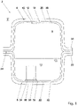
- FIG. 3 shows an embodiment of a liquid container 42 according to the invention in a cross section.
- the same features are assigned the same reference symbols in comparison to the exemplary embodiments described above.
- the liquid container 42 differs from the liquid container 2 in that the half-shells 4, 6 are bonded to one another in a connection area 44, the first carrier layer 12 being bonded to the second carrier layer 16 in the connection area 44.
- the first barrier layer 14 and the second barrier layer 18 are spaced apart from one another in the connection region, with there being no contact between the first barrier layer 14 and the second barrier layer 18 .
- Solidified melt 46 of a material of the first carrier layer 12 and the second carrier layer 16 are arranged between the barrier layers 14 , 18 . It goes without saying that there is local intermixing of the material of the first carrier layer 14 and the second carrier layer 16 in the connecting region 44 .
- the barrier layers 14, 18 are completely surrounded by the carrier layers 12, 16 in the connecting region 44 and delimited from an environment U by the carrier layers 12, 16.
- a width b of a permeation path 48 corresponds to the distance between the barrier layers 14, 18.
- a length l of the permeation path 48 is more than twice the width b of the permeation path 48.
- the liquid container 42 has been produced by means of heated mirror welding.
- the half-shells 4 and 6 provided by injection molding have first been heated in the connection area 44 by means of a heating mirror 50 .
- projections 52, 54 formed in particular on the webs 28, 30 have been plasticized.
- the half-shells 4, 6 have been pressed against one another, the plasticized material of the projections 52, 54 being pressed between the barrier layers 14, 18. While the half-shells 4.6 are being pressed together, a sealing element 56 is applied to an end face 58 of the webs 28,30.
- FIG. 12 shows another variant of a liquid container 60. This variant is not claimed and is for illustration purposes only.
- the liquid container 60 differs from the examples described above by the asymmetrical structure of the first half-shell 4 compared to the second half-shell 6.
- the first half-shell 4 forms a cover of the second half-shell 6.
- a first barrier layer 62 and a second barrier layer 64 are also provided, which have a five-layer structure.
- the first barrier layer 62 has a central layer made of EVOH, which is covered on two sides by adhesion promoter layers made of LDPE.
- the LDPE layers are in turn bordered on two sides by HDPE layers.
- the five-layer barrier film 62 formed in this way has been materially bonded to the first carrier layer 12 in the injection molding process.
- the first carrier layer 12 is also formed from an HDPE, the material connection between the first carrier layer 12 and the first barrier layer 62 being of the same type.
- first half-shell 4 and the second half-shell 6 are initially provided separately from one another.
- first half-shell 4 and the second half-shell 6 are pressed against one another and bonded to one another by means of a laser welding device 26, as already referred to above 2 has been discussed.
- the first carrier layer 12 and the second carrier layer 16 of the liquid container 60 are at a distance from one another in the connection region 24 . There is therefore no direct contact between the first carrier layer 12 and the second carrier layer 16.
- the first barrier layer 14 and the second barrier layer 18 form an essentially closed barrier bubble around the storage volume 8, with the restrictions already discussed above for any inlets and outlets for fluid flows.
- FIG. 6 shows a further variant of a liquid container 66 according to the invention.
- the first half-shell 4 and the second half-shell 6 are analogous to im 4 discussed exemplary embodiment has been welded together by heating mirror welding using a heating mirror 50 .
Landscapes
- Engineering & Computer Science (AREA)
- Mechanical Engineering (AREA)
- Physics & Mathematics (AREA)
- Sustainable Energy (AREA)
- Sustainable Development (AREA)
- Chemical & Material Sciences (AREA)
- Combustion & Propulsion (AREA)
- Transportation (AREA)
- Life Sciences & Earth Sciences (AREA)
- Optics & Photonics (AREA)
- Health & Medical Sciences (AREA)
- Electromagnetism (AREA)
- Toxicology (AREA)
- Rigid Containers With Two Or More Constituent Elements (AREA)
- Packages (AREA)
- Injection Moulding Of Plastics Or The Like (AREA)
- Lining Or Joining Of Plastics Or The Like (AREA)
- Cooling, Air Intake And Gas Exhaust, And Fuel Tank Arrangements In Propulsion Units (AREA)
Description
Die vorliegende Erfindung betrifft einen Flüssigkeitsbehälter für ein Kraftfahrzeug und ein Verfahren zum Herstellen eines Flüssigkeitsbehälters.The present invention relates to a liquid container for a motor vehicle and a method for manufacturing a liquid container.
In modernen Kraftfahrzeugen werden eine Vielzahl von Betriebsflüssigkeiten mitgeführt, wie z.B. Kraftstoff, Harnstofflösung zur Abgasnachbehandlung oder Kühlflüssigkeit. Die Flüssigkeiten sind jeweils in einem Flüssigkeitsbehälter aufgenommen. Beispielsweise dienen Kunststoffkraftstoffbehälter zur Bevorratung von Kraftstoff.A large number of operating fluids are carried in modern motor vehicles, such as fuel, urea solution for exhaust gas aftertreatment or coolant. The liquids are each accommodated in a liquid container. For example, plastic fuel tanks are used to store fuel.
Derartige Kunststoffkraftstoffbehälter sollen idealerweise leicht, crashsicher und emissionsarm sein. Bezüglich der Emission müssen die strenger werdenden gesetzlichen Grenzwerte der maximal zulässigen Kraftstoffverdunstungsemissionen von Kohlenwasserstoffen in die Umwelt eingehalten werden. Dies erfordert die Vermeidung von Kraftstoffleckagen unter allen Betriebsbedingungen, wie z.B. bei der Betankung, inklusive der Betankungsentlüftung, bei der Betriebsentlüftung, also der Kraftstoffausgasung bei einem Temperaturanstieg eines Tanksystems, sowie der Diffusion der Kohlenwasserstoffe durch die Behälterwandung.Such plastic fuel tanks should ideally be light, crash-proof and low-emission. With regard to emissions, the stricter legal limit values for the maximum permissible fuel evaporative emissions of hydrocarbons into the environment must be observed. This requires the avoidance of fuel leaks under all operating conditions, such as during refueling, including refueling venting, during operational venting, ie fuel outgassing when the temperature of a tank system rises, and the diffusion of hydrocarbons through the container wall.
Um die Diffusion durch die Behälterwandung gering zu halten, weisen bekannte Kraftstoffbehälter eine Diffusionsbarriere auf. Soweit ein solcher Kraftstoffbehälter durch Zusammensetzen zweier spritzgegossener Halbschalen gebildet ist, kann beispielsweise für jede Halbschale eine außenliegende Barriereschicht an einem Trägermaterial angeordnet sein, um etwaige im Spritzguss integrierte, innenliegende Anschluss- oder Formelemente des Trägermaterials in dem Vorratsvolumen des Flüssigkeitsbehälters ohne eine Durchbrechung der Barriereschicht anzuordnen. Hierbei ist nachteilig, dass die außenliegende Barriereschicht mechanischer Beanspruchung ausgesetzt ist, wie z.B. Steinschlag oder dergleichen, und die Barriereschicht lokal zerstört werden kann. Hierdurch kann es zu einer erhöhten diffusionsbedingten Emission eines in dem Kraftstoffbehälter bevorratenden Kraftstoffs in die Umgebung kommen.In order to keep diffusion through the tank wall low, known fuel tanks have a diffusion barrier. If such a fuel tank is formed by assembling two injection-molded half-shells, an external barrier layer can be arranged on a carrier material for each half-shell, for example, in order to arrange any internal connection or shaped elements of the carrier material integrated in the injection molding in the storage volume of the liquid tank without breaking through the barrier layer . The disadvantage here is that the outer barrier layer is exposed to mechanical stress, such as stone chipping or the like, and the barrier layer can be destroyed locally. This can lead to an increased diffusion-related emission of a fuel stored in the fuel tank into the environment.
In diesem Zusammenhang ist beispielsweise aus dem Dokument
Dokument
Weiter ist aus dem Dokument
Das Dokument
Aus dem Dokument
Das Dokument
Vor diesem Hintergrund liegt der Erfindung die technische Problemstellung zugrunde, einen Flüssigkeitsbehälter und ein Verfahren zum Herstellen eines Flüssigkeitsbehälters anzugeben, welche die voranstehend beschriebenen Nachteile nicht oder zumindest in geringerem Maße aufweisen, und insbesondere eine verringerte diffusionsbedingte Emission eines Flüssigkeitsbehälters ermöglichen.Against this background, the invention is based on the technical problem of specifying a liquid container and a method for producing a liquid container which do not have the disadvantages described above, or at least do so to a lesser extent, and in particular enable reduced diffusion-related emissions from a liquid container.
Die voranstehend beschriebene technische Problemstellung wird jeweils gelöst durch einen Flüssigkeitsbehälter nach Anspruch 1 und ein Verfahren nach Anspruch 7. Weitere Ausgestaltungen der Erfindung ergeben sich aus den abhängigen Ansprüchen und der nachstehenden Beschreibung.The technical problem described above is solved in each case by a liquid container according to the claim 1 and a method according to claim 7. Further refinements of the invention result from the dependent claims and the following description.
Gemäß einem ersten Aspekt betrifft die Erfindung einen Flüssigkeitsbehälter für ein Kraftfahrzeug, mit einer ersten Halbschale und mit einer zweiten Halbschale, wobei die Halbschalen ein Vorratsvolumen zur Aufnahme von Flüssigkeit begrenzen, wobei die erste Halbschale eine erste Trägerschicht und eine erste Barriereschicht hat, wobei die zweite Halbschale eine zweite Trägerschicht und eine zweite Barriereschicht hat, wobei die erste Barriereschicht auf einer innenliegenden, dem Vorratsvolumen zugewandten Seite der ersten Trägerschicht angeordnet ist und wobei die zweite Barriereschicht auf einer innenliegenden, dem Vorratsvolumen zugewandten Seite der zweiten Trägerschicht angeordnet ist. Die Halbschalen sind in einem Verbindungsbereich stoffschlüssig miteinander verbunden, wobei die erste Trägerschicht in dem Verbindungsbereich stoffschlüssig mit der zweiten Trägerschicht verbunden ist, und die erste Barriereschicht und die zweite Barriereschicht sind in dem Verbindungsbereich zueinander beabstandet, wobei kein Kontakt zwischen der ersten Barriereschicht und der zweiten Barriereschicht besteht. Erstarrte Schmelze eines Materials der ersten Trägerschicht und/oder eines Materials der zweiten Trägerschicht ist zwischen den Barriereschichten angeordnet.According to a first aspect, the invention relates to a liquid container for a motor vehicle, having a first half-shell and a second half-shell, the half-shells delimiting a storage volume for holding liquid, the first half-shell having a first carrier layer and a first barrier layer, the second Half-shell has a second carrier layer and a second barrier layer, the first barrier layer being arranged on an inner side of the first carrier layer facing the storage volume and the second barrier layer being arranged on an inner side of the second carrier layer facing the storage volume. The half-shells are connected to one another in a materially bonded manner in a connection area, with the first carrier layer being bonded to the second carrier layer in the connection area, and the first barrier layer and the second barrier layer being spaced apart from one another in the connection area, with no contact between the first barrier layer and the second barrier layer exists. Solidified melt of a material of the first carrier layer and/or of a material of the second carrier layer is arranged between the barrier layers.
Durch die innenliegende Anordnung der Barriereschichten können die Barriereschichten vor mechanischer Beanspruchung, wie zum Beispiel durch Steinschlag oder dergleichen, geschützt werden. Die strukturelle Integrität der Barriereschichten wird demnach im Vergleich zu Flüssigkeitsbehältern mit außenliegender Barriereschicht nicht durch Umgebungseinflüsse beeinträchtigt. Auf diese Weise kann die Barrierewirkung der Barriereschichten, die einer diffusionsbedingten Emission von beispielsweise in dem Flüssigkeitsbehälter bevorratetem Kraftstoff entgegenwirkt, dauerhaft gewährleistet werden.By arranging the barrier layers on the inside, the barrier layers can be protected from mechanical stress, such as from stone chipping or the like. The structural integrity of the barrier layers is therefore not impaired by environmental influences in comparison to liquid containers with an external barrier layer. In this way, the barrier effect of the barrier layers, which is a diffusion-induced emission of, for example counteracts the fuel stored in the liquid tank, can be permanently guaranteed.
Bei dem Flüssigkeitsbehälter kann es sich insbesondere um einen Kunststoffkraftstoffbehälter für ein Kraftfahrzeug handeln, der zur Bevorratung von Kraftstoff zum Antrieb eines Verbrennungsmotors eingerichtet ist. Die Barriereschichten und/oder die Trägerschichten sind insbesondere dazu geeignet mit einem Diesel- oder Benzinkraftstoff in Kontakt zu sein. Der Werkstoff der Barriereschicht und der Werkstoff der Trägerschicht müssen daher hinsichtlich ihrer Quelleigenschaften dazu geeignet sein, in unmittelbarem Kontakt mit einem flüssigen Kraftstoff zu stehen. Sowohl der Trägerwerkstoff als auch die Barriereschicht müssen hinsichtlich ihrer chemischen Beständigkeit und Quellungseigenschaften für den Einsatz in direktem Kraftstoffkontakt geeignet sein.The liquid container can in particular be a plastic fuel container for a motor vehicle, which is designed to store fuel for driving an internal combustion engine. The barrier layers and/or the carrier layers are particularly suitable for being in contact with a diesel or petrol fuel. With regard to their swelling properties, the material of the barrier layer and the material of the carrier layer must therefore be suitable for being in direct contact with a liquid fuel. Both the carrier material and the barrier layer must be suitable for use in direct contact with fuel in terms of their chemical resistance and swelling properties.
Die einlagige oder mehrlagige Trägerschicht kann einen oder mehrere der folgenden Werkstoffe aufweisen oder aus einem oder mehreren der folgenden Werkstoffe bestehen: Elastomer, thermoplastisches Elastomer, HDPE (High-density polyethylene), faserverstärktes Polyamid, PA (Polyamid), teilaromatisches Polyamid, schlagzähes Polyamid.The single-layer or multi-layer carrier layer can have one or more of the following materials or consist of one or more of the following materials: elastomer, thermoplastic elastomer, HDPE (high-density polyethylene), fiber-reinforced polyamide, PA (polyamide), partially aromatic polyamide, impact-resistant polyamide.
Die einlagige oder mehrlagige Barriereschicht kann einen oder mehrere der folgenden Werkstoffe aufweisen oder aus einem oder mehreren der folgenden Werkstoffe bestehen: EVOH (Ethylen-Vinylalkohol-Copolymer), LDPE (Low-density polyethylene), PEEK (Polyetheretherketon), PA (Polyamid), teilaromatisches Polyamid, HDPE (High-density polyethylene), Fluorpolymer. Z.B. kann die Barriereschicht dreilagig aus PA und EVOH aufgebaut sein, wobei eine zentrale EVOH Lage zweiseitig von PA-Deckschichten bedeckt bzw. eingefasst ist. Es können auch ein beispielsweise sechslagiger Wandungsaufbau oder ein fünflagiger Aufbau aus HDPE, LDPE und EVOH vorgesehen sein, wobei eine zentrale Schicht aus EVOH zweiseitig von jeweils einer LDPE Schicht bedeckt ist, und wobei die LDPE-Schichten ihrerseits wiederum von HDPE-Schichten bedeckt sind.The single-layer or multi-layer barrier layer can have one or more of the following materials or consist of one or more of the following materials: EVOH (ethylene vinyl alcohol copolymer), LDPE (low-density polyethylene), PEEK (polyetheretherketone), PA (polyamide), semi-aromatic polyamide, HDPE (high-density polyethylene), fluoropolymer. For example, the barrier layer can be constructed in three layers from PA and EVOH, with a central EVOH layer being covered or bordered on two sides by PA cover layers. It can also be provided, for example, a six-layer wall structure or a five-layer structure made of HDPE, LDPE and EVOH, with a central layer of EVOH is covered on two sides by a respective LDPE layer, and the LDPE layers are in turn covered by HDPE layers.
Bei der ersten Halbschale kann es sich um eine Oberschale eines Kunststoffkraftstoffbehälters für ein Kraftfahrzeug handeln. Bei der zweiten Halbschale kann es sich um eine Unterschale des Kunststoffkraftstoffbehälters handeln.The first half-shell can be an upper shell of a plastic fuel tank for a motor vehicle. The second half-shell can be a lower shell of the plastic fuel tank.
Die Oberschale ist im Einbauzustand dem Fahrzeug zugewandt. Die Unterschale ist im fertig montierten Zustand dem Fahrzeug abgewandt bzw. der Straße oder Fahrbahn zugewandt.When installed, the upper shell faces the vehicle. In the fully assembled state, the lower shell faces away from the vehicle or faces the street or lane.
Es kann vorgesehen sein, dass die erste Barriereschicht die dem Vorratsvolumen zugewandte Seite der ersten Trägerschicht im Wesentlichen vollständig bedeckt. Alternativ oder ergänzend kann vorgesehen sein, dass die zweite Barriereschicht die dem Vorratsvolumen zugewandte Seite der zweiten Trägerschicht im Wesentlichen vollständig bedeckt. Auf diese Weise kann eine zuverlässige Kapselung einer in dem Flüssigkeitsbehälter bevorrateten Flüssigkeit erreicht werden.Provision can be made for the first barrier layer to essentially completely cover that side of the first carrier layer which faces the storage volume. Alternatively or additionally, it can be provided that the second barrier layer essentially completely covers the side of the second carrier layer facing the storage volume. In this way, reliable encapsulation of a liquid stored in the liquid container can be achieved.
Nach einer nicht beanspruchten alternativen Ausgestaltung des Flüssigkeitsbehälters ist vorgesehen, dass die Halbschalen in einem Verbindungsbereich stoffschlüssig miteinander verbunden sind, wobei die erste Barriereschicht in dem Verbindungsbereich stoffschlüssig mit der zweiten Barriereschicht verbunden ist, und dass die erste Trägerschicht und die zweite Trägerschicht in dem Verbindungsbereich zueinander beabstandet sind, wobei kein Kontakt zwischen der ersten Trägerschicht und der zweiten Trägerschicht besteht und wobei die Trägerschichten die Barriereschichten zweiseitig einfassen.According to an alternative configuration of the liquid container that is not claimed, it is provided that the half-shells are connected to one another in a materially bonded manner in a connection area, with the first barrier layer being connected to the second barrier layer in a materially bonded manner in the connection area, and that the first carrier layer and the second carrier layer are connected to one another in the connection area are spaced apart, there being no contact between the first carrier layer and the second carrier layer and the carrier layers enclosing the barrier layers on two sides.
Durch die stoffschlüssige Verbindung der Barriereschichten kann eine im Wesentlichen geschlossene Barriereblase gebildet werden, die das Vorratsvolumen des Flüssigkeitsbehälters im Wesentlichen vollständig einfasst, mit der Einschränkung, dass die für einen Tank obligatorischen Anschlüsse wie Einfüllstutzen, Entlüftung und/oder Entnahmeöffnung vorgesehen sind. Auf diese Weise kann eine diffusionsbedingte Emission zuverlässig begrenzt werden. Wenn vorliegend davon gesprochen wird, dass die Barriereschichten das Vorratsvolumen im Wesentlichen vollständig einfassen, so betrifft dies daher insbesondere die Vermeidung eines Permeationspfads im Verbindungbereich zwischen den Halbschalen und es versteht sich, dass zum Befüllen des Flüssigkeitsbehälters, z.B. mit Kraftstoff, und zur Entnahme des Kraftstoffs aus dem Flüssigkeitsbehälters Zuleitungen und Abgänge und/oder Entlüftungsventile vorgesehen sind, im Bereich derer die erste oder zweite Barriereschicht lokal durchbrochen ist. Es können demnach die Wandung einer Halbschale durchdringende Anschlussöffnungen vorgesehen sein. Die Anschlussöffnungen können im Spritzgussverfahren hergestellt worden sein.A substantially closed barrier bubble can be formed by the integral connection of the barrier layers which essentially completely encloses the storage volume of the liquid container, with the restriction that the connections that are obligatory for a tank, such as filler neck, ventilation and/or extraction opening, are provided. In this way, a diffusion-related emission can be reliably limited. When it is said here that the barrier layers essentially completely enclose the storage volume, this relates in particular to the avoidance of a permeation path in the connecting area between the half-shells and it goes without saying that for filling the liquid container, e.g. with fuel, and for removing the fuel supply lines and outlets and/or vent valves are provided from the liquid container, in the region of which the first or second barrier layer is locally breached. Accordingly, connection openings penetrating the wall of a half-shell can be provided. The connection openings can have been produced using the injection molding process.
Nach einer weiteren nicht beanspruchten alternativen Ausgestaltung des Flüssigkeitsbehälters ist vorgesehen, dass wenigstens eine der Halbschalen in dem Verbindungsbereich zumindest teilweise aus einem lasertransparenten Material gebildet ist, wobei die stoffschlüssige Verbindung mittels Laserdurchstrahlschweißen gebildet worden ist.According to a further alternative embodiment of the liquid container that is not claimed, at least one of the half-shells in the connection area is formed at least partially from a laser-transparent material, with the bonded connection being formed by means of laser transmission welding.
Es kann dabei vorgesehen sein, dass die erste Trägerschicht in dem Verbindungsbereich zumindest teilweise aus einem lasertransparenten Material gebildet ist. In diesem Fall kann ein von einer Laserschweißeinrichtung erzeugter Laserstrahl die erste Trägerschicht durchdringen und beispielsweise von der ersten Barriereschicht absorbiert werden, wodurch es zu einem lokalen Aufschmelzen der ersten Barriereschicht und der zweiten Barriereschicht und zu einem stoffschlüssigen Verbinden derselben kommt.It can be provided that the first carrier layer in the connection area is formed at least partially from a laser-transparent material. In this case, a laser beam generated by a laser welding device can penetrate the first carrier layer and be absorbed by the first barrier layer, for example, resulting in local melting of the first barrier layer and the second barrier layer and a material connection of the same.
In einem nicht beanspruchten Alternativ kann dabei vorgesehen sein, dass sowohl die erste Trägerschicht als auch die erste Barriereschicht in dem Verbindungsbereich zumindest teilweise aus einem lasertransparenten Material gebildet sind. In diesem Fall kann ein von einer Laserschweißeinrichtung erzeugter Laserstrahl die erste Trägerschicht und die erste Barriereschicht durchdringen und kann von der zweiten Barriereschicht absorbiert werden, die infolgedessen aufgeschmolzen wird und wobei eine stoffschlüssige Verbindung zwischen der zweiten Barriereschicht und der ersten Barriereschicht gebildet werden kann.In an alternative that is not claimed, it can be provided that both the first carrier layer and the first barrier layer in the connection area are formed at least partially from a laser-transparent material. In this case, a laser beam generated by a laser welding device can penetrate the first carrier layer and the first barrier layer and can be absorbed by the second barrier layer, which is consequently melted and a material bond can be formed between the second barrier layer and the first barrier layer.
Mit anderen Worten kann dabei vorgesehen sein, dass die erste Barriereschicht aus einem lasertransparenten oder einem laserundurchlässigen Material gebildet sein kann, während die erste Trägerschicht aus lasertransparentem Material gebildet ist. Es kann dabei weiter vorgesehen sein, dass die zweite Trägerschicht aus einem lasertransparenten Material gebildet ist, wobei die zweite Barriereschicht aus einem lasertransparenten Material oder einem nicht lasertransparenten Material gebildet sein kann. Es kann vorgesehen sein, dass sowohl die erste Trägerschicht als auch die zweite Trägerschicht aus einem lasertransparenten Material gebildet sind.In other words, it can be provided that the first barrier layer can be formed from a laser-transparent or a laser-opaque material, while the first carrier layer is formed from laser-transparent material. It can further be provided that the second carrier layer is formed from a laser-transparent material, it being possible for the second barrier layer to be formed from a laser-transparent material or a non-laser-transparent material. It can be provided that both the first carrier layer and the second carrier layer are formed from a laser-transparent material.
Es kann dabei weiter vorgesehen sein, dass beide Trägerschichten und eine Barriereschicht aus lasertransparentem Material gebildet sind. Für die Funktionsweise des Prozesses ist es lediglich erforderlich, dass wenigstens eine der Barriereschichten in dem Verbindungsbereich aus einem nicht lasertransparenten, also einem laserabsorbierenden Material, gebildet ist, sodass wenigstens eine der Barriereschichten zur Aufschmelzung infolge des Energieeintrags durch den Laser geeignet ist.It can further be provided that both carrier layers and a barrier layer are formed from laser-transparent material. For the process to function, it is only necessary that at least one of the barrier layers in the connection area is made of a non-laser-transparent, i.e. a laser-absorbing material, so that at least one of the barrier layers is suitable for melting as a result of the energy input from the laser.
Beispielsweise können die erste und die zweite Trägerschicht durch Heizspiegelschweißen miteinander verbunden worden sein, um eine kostengünstige und haltbare stoffschlüssige Verbindung zu erzielen.For example, the first and the second carrier layer can have been connected to one another by hot plate welding in order to achieve a cost-effective and durable bonded connection.
Gemäss der Erfindung kann es vorgesehen sein, dass die Barriereschichten in dem Verbindungsbereich vollständig von den Trägerschichten umschlossen und durch die Trägerschichten gegenüber einer Umgebung abgegrenzt sind. Auf diese Weise können die Barriereschichten vor Umgebungseinflüssen geschützt werden.According to the invention, it can be provided that the barrier layers in the connection area are completely surrounded by the carrier layers and are delimited by the carrier layers from the environment. In this way, the barrier layers can be protected from environmental influences.
Es kann vorgesehen sein, dass in dem Verbindungsbereich zwischen den zueinander beabstandeten Barriereschichten ein Permeationspfad gebildet ist, und dass in einem Querschnitt betrachtet eine Länge des Permeationspfads größer oder gleich einem Zweifachen der Breite des Permeationspfads ist, wobei die Breite des Permeationspfads dem Abstand der Barriereschichten in dem Verbindungsbereich entspricht. Durch das angegebene Längen- und Breiten-Verhältnis kann beispielsweise die diffusionsbedingte Emission eines Kraftstoffs entlang des Permeationspfads auf einem zulässigen Niveau gehalten werden. Bei dem Material der Trägerschichten kann es sich z.B. um ein HDPE handeln.Provision can be made for a permeation path to be formed in the connection area between the spaced-apart barrier layers, and for the length of the permeation path, viewed in cross-section, to be greater than or equal to twice the width of the permeation path, the width of the permeation path corresponding to the distance between the barrier layers in corresponds to the connection area. For example, the specified length and width ratio can be used to keep the diffusion-related emission of a fuel along the permeation path at a permissible level. The material of the carrier layers can be an HDPE, for example.
Es kann vorgesehen sein, dass in einem Querschnitt betrachtet eine Länge des Permeationspfads größer ist, als eine Wanddicke der ersten Halbschale und der zweiten Halbschale.It can be provided that, viewed in a cross section, a length of the permeation path is greater than a wall thickness of the first half-shell and the second half-shell.
Gemäß einer weiteren Ausgestaltung des Flüssigkeitsbehälters ist vorgesehen, dass wenigstens eine der Halbschalen in dem Verbindungsbereich einen Steg hat, wobei die stoffschlüssige Verbindung entlang des Stegs gebildet ist. Der Steg kann insbesondere formschlüssig in einer zumindest abschnittsweise komplementär geformten Aufnahme der jeweils anderen Halbschale sitzen.According to a further embodiment of the liquid container, it is provided that at least one of the half-shells has a web in the connection area, with the material connection being formed along the web. In particular, the web can be seated in a form-fitting manner in a receptacle of the respective other half-shell that is shaped in a complementary manner, at least in sections.
Bei dem Steg kann es sich um einen umfangsseitig umlaufenden Steg handeln. Der Steg kann dazu dienen, eine definierte Anlage zwischen den Halbschalen zu erreichen.The web can be a web running around the circumference. The web can serve to achieve a defined contact between the half-shells.
Beide Halbschalen können einen umlaufenden Steg haben, der jeweils zur Ausbildung einer definierten Anlage zwischen den Halbschalen dient, beispielsweise für einen Schweißprozess.Both half-shells can have a circumferential ridge, which is used to form a defined contact between the half-shells, for example for a welding process.
Bei dem Steg bzw. den Stegen kann es sich um seitlich auskragende Schweißkragen handeln.The web or webs can be welding collars projecting laterally.
Es kann vorgesehen sein, dass wenigstens eine der Barriereschichten eine einlagige Folie ist, die in einem Spritzgussverfahren stoffschlüssig mit der zugeordneten Trägerschicht verbunden worden ist. Hierzu kann die Folie in einer Werkzeughälfte eines Spritzgusswerkzeugs aufgenommen sein und mit plastifiziertem Trägerwerkstoff angespritzt bzw. hinterspritzt werden. Durch den Spritzgussvorgang wird eine stoffschlüssige Verbindung zwischen der Barrierefolie und der Trägerschicht gebildet. So kann eine Halbschale mit Trägerschicht und Barrierefolie kostengünstig und unter geringem Materialeinsatz hergestellt werden.Provision can be made for at least one of the barrier layers to be a single-layer film which has been cohesively connected to the associated carrier layer in an injection molding process. For this purpose, the film can be accommodated in one half of an injection molding tool and sprayed or back-injected with plasticized carrier material. The injection molding process creates a material connection between the barrier film and the carrier layer. In this way, a half-shell with a carrier layer and a barrier film can be produced inexpensively and with little use of materials.
Alternativ oder ergänzend kann vorgesehen sein, dass wenigstens eine der Barriereschichten eine mehrlagige Folie ist, die in einem Spritzgussverfahren stoffschlüssig mit der zugeordneten Trägerschicht verbunden worden ist. Bei einer solchen mehrlagigen Folie kann es sich beispielsweise um eine fünfschichtige Folie handeln, die eine zentrale Schicht aus EVOH (Ethylen-Vinylalkohol-Copolymer) enthält, die EVOH-Schicht zweiseitig von einer LDPE (Low-density polyethylene) Schicht bedeckt ist, und wobei die LDPE-Schichten ihrerseits wiederum von HDPE-Schichten (High-density polyethylene) bedeckt sind.Alternatively or in addition, it can be provided that at least one of the barrier layers is a multi-layer film that has been cohesively connected to the associated carrier layer in an injection molding process. Such a multilayer film can be, for example, a five-layer film that contains a central layer of EVOH (ethylene-vinyl alcohol copolymer), the EVOH layer is covered on two sides by an LDPE (low-density polyethylene) layer, and where the LDPE layers are in turn covered by HDPE layers (high-density polyethylene).
In einem nicht beanspruchten Beispiel, können die Deckschichten einer mehrlagigen Folie insbesondere artgleich zu dem Trägerwerkstoff ausgebildet sein, um eine zuverlässige stoffschlüssige Verbindung zwischen dem Trägerwerkstoff und der Barrierefolie zu erreichen. So kann die Barrierewirkung einer mehrschichtigen Folie beispielsweise maßgeblich durch eine EVOH-Schicht bereitgestellt werden, während die LDPE-Schichten jeweils als Haftvermittler zu den außenliegenden HDPE-Schichten dienen und eine der HDPE-Schichten ihrerseits wiederum zur zuverlässigen Anhaftung bzw. stoffschlüssigen Verbindung mit einem Trägermaterial vorgesehen sein kann, wobei das Trägermaterial ebenfalls aus dem HDPE der Deckschichten der Barrierefolie bestehen kann.In an example that is not claimed, the cover layers of a multi-layer film can in particular be of the same type as the carrier material in order to achieve a reliable material connection between the carrier material and the barrier film. For example, the barrier effect of a multi-layer film can be largely provided by an EVOH layer, while the LDPE layers each serve as an adhesion promoter to the outer HDPE layers and one of the HDPE layers in turn for reliable adhesion or material connection with a carrier material can be provided, wherein the carrier material can also consist of the HDPE of the cover layers of the barrier film.
Nach einer weiteren Ausgestaltung des Flüssigkeitsbehälters ist vorgesehen, dass auf einer dem Vorratsvolumen zugewandten Seite wenigstens einer der Barriereschichten lokal ein Kunststoff angespritzt ist, der zur Anbindung von Formelementen, Anschlussteilen oder Funktionseinheiten dient. Hierbei kann beispielsweise nach dem Herstellen der Trägerschicht im Spritzguss auf einer der Trägerschicht abgewandten Seite der Barriereschicht lokal ein Trägerwerkstoff durch sequenzielles Spritzgießen an die Barriereschicht angespritzt werden. Der lokal angespritzte Kunststoff kann beispielsweise ein Sockel oder plattenartiges Element aus Trägermaterial sein, an dem beispielsweise ein Schwalltopf angeschweißt oder angeklebt werden kann. Auf diese Weise kann eine Funktionseinheit im Bereich einer Halbschale mit innenliegender Barriereschicht angeordnet werden, ohne die Barriereschicht zu durchbrechen oder zu unterbrechen. Somit kann die Barrierewirkung der jeweiligen Barriereschicht aufrechterhalten werden, wobei zudem Formelemente, Anschlussteile oder Funktionseinheiten im Bereich des lokal angespritzten Kunststoffs der Halbschale angeordnet werden können.According to a further embodiment of the liquid container, it is provided that on a side facing the storage volume at least one of the barrier layers is locally injection-moulded a plastic, which is used for the connection of shaped elements, connecting parts or functional units. In this case, for example after the production of the carrier layer by injection molding, a carrier material can be sprayed onto the barrier layer locally by sequential injection molding on a side of the barrier layer facing away from the carrier layer. The locally injected plastic can be, for example, a base or plate-like element made of carrier material, to which, for example, a surge pot can be welded or glued. In this way, a functional unit can be arranged in the area of a half-shell with an internal barrier layer without breaking through or interrupting the barrier layer. The barrier effect of the respective barrier layer can thus be maintained, it also being possible for shaped elements, connection parts or functional units to be arranged in the area of the locally injection-moulded plastic of the half-shell.
Die Wanddicke einer der Trägerschichten für sich genommen kann 2 mm bis 6 mm betragen, insbesondere 2 mm bis 4 mm betragen. Diese geringe Wanddicke kann über beispielsweise 90 % der gesamten Oberfläche einer Halbschale ausgebildet sein, wobei lokale Verstärkungsrippen, Abgänge oder andere lokale Verdickungen vorgesehen sein können.The wall thickness of one of the carrier layers per se can be 2 mm to 6 mm, in particular 2 mm to 4 mm. This small wall thickness can be formed over, for example, 90% of the entire surface of a half-shell, with local reinforcement ribs, outlets or other local thickenings being able to be provided.
Die Dicke einer der Barriereschichten, insbesondere Barrierefolien, kann 100 µm bis 1000 µm betragen.The thickness of one of the barrier layers, in particular barrier films, can be 100 μm to 1000 μm.
Gemäß einem zweiten Aspekt betrifft die Erfindung ein Verfahren gemäss Anspruch 7.According to a second aspect, the invention relates to a method according to claim 7.
Mithilfe des erfindungsgemäßen Verfahrens kann ein Flüssigkeitsbehälter hergestellt werden, bei dem die strukturelle Integrität der Barriereschichten durch ihre innenliegende Anordnung vor mechanischer Beanspruchung geschützt ist.With the aid of the method according to the invention, a liquid container can be produced in which the structural integrity of the barrier layers is protected from mechanical stress by their internal arrangement.
Alternativ kann vorgesehen sein, dass
- das Verbinden der Halbschalen durch Heizspiegelschweißen erfolgt, mit den Verfahrensschritten:
- Erhitzen und Plastifizieren wenigstens eines an einem Steg einer Trägerschicht gebildeten Vorsprungs mit einem Heizspiegel
- Aneinanderdrücken der Halbschalen wobei plastifiziertes Material des Vorsprungs zwischen die Barriereschichten gedrückt wird.
- the half-shells are connected by hot plate welding, with the process steps:
- Heating and plasticizing at least one projection formed on a web of a carrier layer with a heating mirror
- Pressing the half-shells together whereby plasticized material of the projection is pressed between the barrier layers.
Durch das Heizspiegelschweißen kann eine zuverlässige und kostengünstige Verbindung zwischen Trägerschichten erreicht werden.A reliable and cost-effective connection between carrier layers can be achieved by hot plate welding.
Weiter kann während des Aneinanderdrückens der Halbschalen ein Dichtelement an eine Stirnseite des Stegs angelegt wird. Durch das Dichtelement kann verhindert werden, dass Schmelze seitlich zwischen den Halbschalen aus dem Verbindungsbereich gedrückt wird. Das Dichtelement sorgt dafür, dass plastifiziertes Material des Vorsprungs gezielt zwischen die Barriereschichten gelangt.Furthermore, while the half-shells are being pressed against one another, a sealing element can be applied to an end face of the web. The sealing element can prevent melt from being pushed out of the connection area laterally between the half-shells. The sealing element ensures that plasticized material of the projection reaches between the barrier layers in a targeted manner.
Es kann vorgesehen sein, dass jede der Halbschalen einen umlaufenden Steg mit wenigstens einem Vorsprung aufweist, wobei einander zugewandte Vorsprünge beide Halbschalen vor dem Aneinanderdrücken der Halbschalen mithilfe des Heizspiegels plastifiziert werden. Die Vorsprünge können in einem Querschnitt und entlang einer Fügerichtung betrachtet einen Versatz zueinander aufweisen oder im Querschnitt und entlang einer Fügerichtung betrachtet in einer Flucht liegen. Durch die Dimensionierung der Vorsprünge kann die Wandstärke des zwischen den Barriereschichten angeordneten Materials der Trägerschichten und damit der Abstand der Barriereschichten zueinander eingestellt werden.Provision can be made for each of the half-shells to have a circumferential web with at least one projection, with projections facing one another being plasticized on both half-shells before the half-shells are pressed together using the heating mirror. The projections can be offset from one another when viewed in a cross section and viewed along a joining direction, or they can be aligned when viewed in a cross section and along a joining direction. By dimensioning the projections, the wall thickness of the material of the carrier layers arranged between the barrier layers and thus the spacing of the barrier layers from one another can be adjusted.
Die Vorsprünge können, wie auch die Stege, umlaufend sein.Like the webs, the projections can be circumferential.
Nachfolgend wird die Erfindung anhand einer Ausführungsbeispiele darstellenden Zeichnung näher beschrieben es zeigen jeweils schematisch:
- Fig. 1
- einen Flüssigkeitsbehälter in einem Querschnitt; Dieser Flüssigkeitbehälter ist nicht beansprucht und dient nur zu Illustrationszwecken.
- Fig. 2
- die Herstellung des Flüssigkeitsbehälters aus
Fig. 1 ; - Fig. 3
- einen erfindungsgemäßen Flüssigkeitsbehälter in einem Querschnitt;
- Fig. 4
- die Herstellung des Flüssigkeitsbehälters aus
Fig. 3 ; - Fig. 5
- einen weiteren Flüssigkeitsbehälter in einem Querschnitt und dessen Herstellung; Dieser Flüssigkeitbehälter ist nicht beansprucht und dient nur zu Illustrationszwecken.
- Fig. 6
- einen weiteren erfindungsgemäßen Flüssigkeitsbehälter in einem Querschnitt und dessen Herstellung.
- 1
- a liquid container in a cross section; This liquid container is not claimed and is for illustration purposes only.
- 2
- the manufacture of the liquid container
1 ; - 3
- a liquid container according to the invention in a cross section;
- 4
- the manufacture of the liquid container
3 ; - figure 5
- another liquid container in a cross section and its manufacture; This liquid container is not claimed and is for illustration purposes only.
- 6
- another liquid container according to the invention in a cross section and its manufacture.
Bei dem Flüssigkeitsbehälter 2 handelt es sich vorliegend um einen Kunststoffkraftstoffbehälter 2 für ein Kraftfahrzeug. Bei der Flüssigkeit 10 handelt es sich vorliegend um Kraftstoff 10 zum Antrieb eines Verbrennungsmotors.In the present case, the
Die erste Halbschale 4 hat eine erste Trägerschicht 12 und eine erste Barriereschicht 14. Die zweite Halbschale 6 hat eine zweite Trägerschicht 16 und eine zweite Barriereschicht 18. Die erste Barriereschicht 14 ist auf einer dem Vorratsvolumen 8 zugewandten Seite 20 der ersten Trägerschicht 12 angeordnet. Die zweite Barriereschicht 18 ist auf einer dem Vorratsvolumen 8 zugewandten Seite 22 der zweiten Trägerschicht 16 angeordnet.The first half-
Die erste Barriereschicht 14 bedeckt die dem Vorratsvolumen 8 zugewandte Seite 20 der ersten Trägerschicht 12 im Wesentlichen vollständig. Die zweite Barriereschicht 18 bedeckt die dem Vorratsvolumen 8 zugewandte Seite 22 der zweiten Trägerschicht 16 im Wesentlichen vollständig.The
Die Halbschalen 4, 6 sind in einem Verbindungsbereich 24 stoffschlüssig miteinander verbunden. Die erste Barriereschicht 14 ist in dem Verbindungsbereich 24 stoffschlüssig mit der zweiten Barriereschicht 18 verbunden.The half-
Die erste Trägerschicht 12 und die zweite Trägerschicht 16 sind in dem Verbindungsbereich 24 zueinander beabstandet, wobei kein Kontakt zwischen der ersten Trägerschicht 12 und der zweiten Trägerschicht 16 besteht und wobei die Trägerschichten 12, 16 die Barriereschichten 14, 18 zweiseitig einfassen. Es versteht sich, dass der Verbindungsbereich 24 eine vollständig umlaufende, in sich geschlossene stoffschlüssige Verbindung darstellt, sodass die Halbschalen 4, 6 eine im Wesentlichen geschlossene Tankblase bilden.The
Wie voranstehend bereits erwähnt, weist die im Wesentlichen geschlossene Tankblase nicht dargestellte, obligatorische Zu- und Abgänge zum Befüllen, zur Entnahme und Belüftung auf, im Bereich derer eine Barriereschicht lokal unterbrochen ist.As already mentioned above, the essentially closed tank bladder has obligatory inlets and outlets (not shown) for filling, removal and ventilation, in the area of which a barrier layer is locally interrupted.
Wie
In dem vorliegenden Beispiel ist die erste Trägerschicht 12 in dem Verbindungsbereich 24 zumindest teilweise aus lasertransparentem Material gebildet. Gemäß weiteren Beispielen kann vorgesehen sein, dass die erste Trägerschicht vollständig aus lasertransparentem Material hergestellt ist. Gemäß weiteren Ausgestaltungen kann ebenfalls vorgesehen sein, dass die erste Trägerschicht und die erste Barriereschicht in dem Verbindungsbereich zumindest teilweise aus lasertransparentem Material gebildet sind.In the present example, the
Die Halbschalen 4, 6 haben in dem Verbindungsbereich 24 jeweils einen Steg 28, 30. Die stoffschlüssige Verbindung zwischen den Barriereschichten 14, 18 ist entlang der Stege 28,30 gebildet. Bei den Stegen 28, 30 handelt es sich um umfangsseitig umlaufende Stege 28, 30, die jeweils seitlich auskragend erstreckt sind, um eine definierte Anlage zwischen den Halbschalen 4, 6 zur Ausbildung einer Schweißverbindung bereitstellen. Die Stege 28, 30 können jeweils als Schweißkragen 28, 30 bezeichnet werden.The half-
Bei den Barriereschichten 14, 18 handelt es sich vorliegend um einlagige Folien, die im Spritzgussverfahren stoffschlüssig mit den jeweils zugeordneten Trägerschicht 12, 16 stoffschlüssig verbunden worden sind. Gemäß weiterer Beispiele kann vorgesehen sein, dass wenigstens eine Barrierefolie, insbesondere beide Barrierefolien mehrlagig ausgebildet sind, und beispielsweise einen fünfschichtigen Wandungsaufbau, mit einer zentralen EVOH Schicht, zwei die EVOH-Schicht bedeckende LDPE-Schichten, und zwei die LDPE schichten bedeckende HDPE-Schichten aufweisen können.In the present case, the barrier layers 14, 18 are single-layer films which have been cohesively connected to the respectively associated
Auf einer dem Vorratsvolumen 8 zugewandten Seite 32 der Barriereschicht 18 ist lokal ein Kunststoff 34 angespritzt worden, der zur Anbindung eines Schwalltopfs 36 verwendet worden ist. Der Kunststoff 34 bildet einen Sockel 34, an den der Schwalltopf 36 angeschweißt worden ist. Der Schwalltopf 36 ist damit in das Vorratsvolumen 8 integriert worden, ohne die strukturelle Integrität der Barriereschicht 18 zu beeinträchtigen.On a
Gleichermaßen ist auf einer dem Vorratsvolumen 8 zugewandten Seite 38 der Barriereschicht 14 ein Kunststoff 40 angespritzt worden, der zur Anbindung von Formelementen, Anschlussteilen oder Funktionseinheiten dient.Likewise, a plastic 40 has been injection-molded onto a
Der Flüssigkeitsbehälter 42 unterscheidet sich dadurch von dem Flüssigkeitsbehälter 2, dass die Halbschalen 4, 6 in einem Verbindungsbereich 44 stoffschlüssig miteinander verbunden sind, wobei die erste Trägerschicht 12 in dem Verbindungsbereich 44 stoffschlüssig mit der zweiten Trägerschicht 16 verbunden ist.The
Die erste Barriereschicht 14 und die zweite Barriereschicht 18 sind in dem Verbindungsbereich zueinander beabstandet, wobei kein Kontakt zwischen der ersten Barriereschicht 14 und der zweiten Barriereschicht 18 besteht. Erstarrte Schmelze 46 eines Materials der ersten Trägerschicht 12 und der zweiten Trägerschicht 16 sind zwischen den Barriereschichten 14, 18 angeordnet. Es versteht sich, dass es in dem Verbindungsbereich 44 zu einer lokalen Durchmischung des Materials der ersten Trägerschicht 14 und der zweiten Trägerschicht 16 kommt.The
Die Barriereschichten 14, 18 sind in dem Verbindungsbereich 44 vollständig von den Trägerschichten 12, 16 umschlossen und durch die Trägerschichten 12, 16 gegenüber einer Umgebung U abgegrenzt. Eine breite b eines Permeationspfads 48 entspricht dem Abstand der Barriereschichten 14, 18. In dem vorliegenden Querschnitt betrachtet beträgt eine Länge l des Permeationspfads 48 mehr als das Zweifache der Breite b des Permeationspfads 48.The barrier layers 14, 18 are completely surrounded by the carrier layers 12, 16 in the connecting
Wie
Dazu sind insbesondere an den Stegen 28, 30 gebildete Vorsprünge 52, 54 plastifiziert worden. In einem nächsten Schritt sind die Halbschalen 4,6 aneinandergedrückt worden, wobei plastifiziertes Material der Vorsprünge 52, 54 zwischen die Barriereschichten 14, 18 gedrückt wird. Während des Aneinanderdrückens der Halbschalen 4,6 wird ein Dichtelement 56 an eine Stirnseite 58 der Stege 28,30 angelegt.For this purpose,
Der Flüssigkeitsbehälter 60 unterscheidet sich von den vorangehen beschriebenen Beispielen durch den asymmetrischen Aufbau von der ersten Halbschale 4 im Vergleich zur zweiten Halbschale 6. Die erste Halbschale 4 bildet vorliegend einen Deckel der zweiten Halbschale 6.The
Weiter sind eine erste Barriereschicht 62 und eine zweite Barriereschicht 64 vorgesehen, die einen fünflagigen Aufbau haben. Die erste Barriereschicht 62 weist eine zentrale Schicht aus EVOH auf, die zweiseitig von Haftvermittlerschichten aus LDPE bedeckt ist. Die LDPE-Schichten sind ihrerseits wiederum zweiseitig von HDPE-Schichten eingefasst.A
Die in dieser Art gebildete fünflagige Barrierefolie 62 ist im Spritzgussverfahren stoffschlüssig mit der ersten Trägerschicht 12 verbunden worden. Die erste Trägerschicht 12 ist ebenfalls aus einem HDPE gebildet, wobei die stoffschlüssige Verbindung zwischen der ersten Trägerschicht 12 und der ersten Barriereschicht 62 artgleich ist.The five-
Wie im oberen Teil der
Wie auch im Beispiel der
Die erste Barriereschicht 14 und die zweite Barriereschicht 18 bilden eine im Wesentlichen geschlossene Barriereblase um das Vorratsvolumen 8, mit den bereits voranstehend diskutierten Einschränkungen für etwaige Zu- und Abgänge für Fluidströme.The
Die erste Halbschale 4 und die zweite Halbschale 6 sind analog zum im
Hierzu sind lokale Vorsprünge 68, 70 der Halbschalen 4,6 mithilfe des Heizspiegels plastifiziert worden. Anschließend ist der Heizspiegel 50 entfernt worden und die Halbschalen 4, 6 sind aneinandergedrückt worden, wobei plastifizierter Werkstoff der Vorsprünge 68, 70 zwischen mehrlagige Barriereschichten 62, 64 gedrückt worden ist. Die Barriereschichten 62, 64 weisen demnach einen Abstand zueinander auf, wobei kein unmittelbarer Kontakt zwischen den Barriereschichten 62, 64 besteht. Auf diese Weise ist zwischen den Barriereschichten 62, 64 analog zur
- 22
- Flüssigkeitsbehälterliquid container
- 44
- erste Halbschalefirst half shell
- 66
- Halbschalehalf shell
- 88th
- Vorratsvolumenstock volume
- 1010
- Flüssigkeitliquid
- 1212
- erste Trägerschichtfirst support layer
- 1414
- erste Barriereschichtfirst barrier layer
- 1616
- zweite Trägerschichtsecond backing layer
- 1818
- zweite Barriereschichtsecond barrier layer
- 2020
- Seiteside
- 2222
- Seiteside
- 2424
- Verbindungsbereichconnection area
- 2626
- Laserschweißeinrichtunglaser welding device
- 2828
- Steg/SchweißkragenBridge/welding collar
- 3030
- Steg/SchweißkragenBridge/welding collar
- 3232
- Seiteside
- 3434
- Kunststoff/Sockelplastic/base
- 3636
- Schwalltopfsurge pot
- 3838
- Seiteside
- 4040
- Kunststoffplastic
- 4242
- Flüssigkeitsbehälterliquid container
- 4444
- Verbindungsbereichconnection area
- 4646
- erstarrte Schmelzesolidified melt
- 4848
- Permeationspfadpermeation path
- 5050
- Heizspiegelheating mirror
- 5252
- Vorsprunghead Start
- 5454
- Vorsprunghead Start
- 5656
- Dichtelementsealing element
- 5858
- Stirnseiteface
- 6060
- Flüssigkeitsbehälterliquid container
- 6262
- erste Barriereschichtfirst barrier layer
- 6464
- zweite Barriereschichtsecond barrier layer
- 6666
- Flüssigkeitsbehälterliquid container
- 6868
- Vorsprunghead Start
- 7070
- Vorsprunghead Start
- ll
- Längelength
- bb
- BreiteBroad
- Uu
- Umgebungvicinity
Claims (10)
- Liquid container for a motor vehicle,- having a first half-shell (4) and- having a second half-shell (6),- wherein the half-shells (4, 6) delimit a storage volume (8) for accommodating liquid (10),- wherein the first half-shell (4) has a first support layer (12) and a first barrier layer (14, 62),- wherein the second half-shell (6) has a second support layer (16) and a second barrier layer (18, 64),- wherein the first barrier layer (14, 62) is situated on an inner side (20) of the first support layer (12) facing the storage volume (8),- wherein the second barrier layer (18, 64) is situated on an inner side of the second support layer (16) facing the storage volume (8).- the half-shells (4, 6) in a connecting area (44) are integrally joined together, the first support layer (12) in the connecting area (44) being integrally joined to the second support layer (16),characterized in that- the first barrier layer (14, 62) and the second barrier layer (18, 64) in the connecting area (44) are spaced apart from one another, with no contact between the first barrier layer (14, 62) and the second barrier layer (18, 64) and- wherein solidified melt (46) of a material of the first support layer (12) and/or of a material of the second support layer (16) is situated between the barrier layers (14, 18, 62, 64).
- Liquid container according to Claim 1, characterized in that- the barrier layers (14, 18, 62, 64) in the connecting area are completely enclosed by the support layers (12, 16) and isolated from the surroundings U by the support layers (12, 16) .
- Liquid container according to Claim 1 or Claim 2, characterized in that- a permeation path (48) is formed in the connecting area (44) between the spaced-apart barrier layers,- a length (1) of the permeation path, viewed in a cross section, is greater than or equal to twice the width (b) of the permeation path,- wherein the width (b) of the permeation path corresponds to the distance between the barrier layers (14, 18, 62, 64) in the connecting area (44).
- Liquid container according to one of Claims 1 to 3, characterized in that- at least one of the half-shells (4, 6) in the connecting area (24, 44) has a nose-piece (28, 30),- wherein the integral bond is formed along the nose-piece (28, 30).
- Liquid container according to one of the preceding Claims, characterized in that- at least one of the barrier layers (14, 18) is a one-ply film (14, 18) that has been integrally joined to the associated support layer (12, 16) in an injection molding process,and/or- at least one of the barrier layers (62, 64) is a multi-ply film (62, 64) that has been integrally joined to the associated support layer (12, 16) in an injection molding process.
- Liquid container according to one of the preceding Claims, characterized in that- a plastic (34, 40) that is used for attaching molded elements, connecting parts, or functional units is locally molded onto a side (32, 38) of at least one of the barrier layers (14, 18, 62, 64) facing the storage volume (8).
- A method for manufacturing a liquid container, having the method steps:- injection molding of a first half-shell (4), the first half-shell (4) having a first support layer (12) and a first barrier layer (14, 62),- injection molding of a second half-shell (6), the second half-shell (6) having a second support layer (16) and a second barrier layer (18, 64),- joining the half-shells (4, 6) in such a way that the half-shells (4, 6) delimit a storage volume (8) for accommodating liquid (10), the first barrier layer (14, 62) being situated on an inner side (20) of the first support layer (12) facing the storage volume, and the second barrier layer (18, 64) being situated on an inner side (22) of the second support layer (16) facing the storage volume (8),the half-shells (4, 6) in a connecting area (44) being integrally joined together, the first support layer (12) in the connecting area (44) being integrally joined to the second support layer (16), the first barrier layer (14, 62) and the second barrier layer (18, 64) in the connecting area (44) being spaced apart from one another, with no contact between the first barrier layer (14, 62) and the second barrier layer (18, 64) and wherein melt (46) of a material of the first support layer (12) and/or of a material of the second support layer (16) is solidified between the barrier layers (14, 18, 62, 64).
- Method according to Claim 7,- wherein the half-shells a(4, 6) are joined by hot plate welding, with the method steps:- heating and plasticizing at least one protrusion (52, 54, 68, 70) that is formed on a nose-piece (28, 30) of a support layer (12, 16), using a hot plate (50)- pressing the half-shells together (4, 6), with plasticized material of the protrusion (52, 54, 68, 70) being pressed between the barrier layers (14, 18, 62, 64).
- Method according to Claim 8,- wherein during the pressing together of the half-shells (4, 6), a sealing element (56) is placed against an end-face side (58) of the nose-piece (28, 30).
- The method according to Claim 8 or Claim 9,- wherein each of the half-shells (4, 6) has a circumferential nose-piece (28, 30) with at least one protrusion (52, 54, 68, 70), wherein protrusions (52, 54, 68, 70) of the two half-shells (4, 6) mutually facing each other are plasticized by means of the hot plate (50) before the half-shells (4, 6) are pressed together.
Applications Claiming Priority (2)
| Application Number | Priority Date | Filing Date | Title |
|---|---|---|---|
| DE102017119707.9A DE102017119707A1 (en) | 2017-08-28 | 2017-08-28 | Liquid container and method of manufacturing a liquid container |
| PCT/EP2018/072928 WO2019042901A1 (en) | 2017-08-28 | 2018-08-24 | LIQUID CONTAINER AND METHOD FOR PRODUCING A LIQUID CONTAINER |
Publications (2)
| Publication Number | Publication Date |
|---|---|
| EP3676080A1 EP3676080A1 (en) | 2020-07-08 |
| EP3676080B1 true EP3676080B1 (en) | 2022-09-14 |
Family
ID=63491584
Family Applications (1)
| Application Number | Title | Priority Date | Filing Date |
|---|---|---|---|
| EP18765378.7A Active EP3676080B1 (en) | 2017-08-28 | 2018-08-24 | Liquid container and method for producing a liquid container |
Country Status (7)
| Country | Link |
|---|---|
| US (1) | US11724591B2 (en) |
| EP (1) | EP3676080B1 (en) |
| JP (1) | JP6929447B2 (en) |
| KR (1) | KR102353440B1 (en) |
| CN (1) | CN111032322B (en) |
| DE (1) | DE102017119707A1 (en) |
| WO (1) | WO2019042901A1 (en) |
Families Citing this family (4)
| Publication number | Priority date | Publication date | Assignee | Title |
|---|---|---|---|---|
| DE102020119063A1 (en) | 2020-07-20 | 2022-01-20 | Deutsches Zentrum für Luft- und Raumfahrt e.V. | Process and device for pretreating a joint contact surface and laminated fiber-plastic composite component |
| DE102020128012A1 (en) * | 2020-10-23 | 2022-04-28 | Röchling Automotive SE & Co. KG | Sandwich motor vehicle tank with turned-out barrier film and at least locally molded thermoplastic material |
| CN114346431A (en) * | 2021-12-29 | 2022-04-15 | 深圳泰德激光技术股份有限公司 | Intersecting line welding method and tank assembly |
| CN116834300A (en) * | 2023-07-10 | 2023-10-03 | 广东新意智能制造有限公司 | Double-plastic-part hot melting process and hot melting equipment |
Family Cites Families (34)
| Publication number | Priority date | Publication date | Assignee | Title |
|---|---|---|---|---|
| JPS5712739B2 (en) | 1973-04-23 | 1982-03-12 | ||
| JPS5666396A (en) * | 1979-11-06 | 1981-06-04 | Honda Motor Co Ltd | Laser welding method |
| DE3009463A1 (en) * | 1980-03-12 | 1981-09-17 | Kautex Werke Reinold Hagen Gmbh, 5300 Bonn | METHOD FOR PRODUCING HOLLOW BODIES FROM PLASTIC |
| SE453820B (en) | 1983-03-22 | 1988-03-07 | Haustrup Plastic As | REMOVABLE CONTAINER |
| JPS59179284A (en) * | 1983-03-30 | 1984-10-11 | Futaba Sangyo Kk | Production of fuel tank for automobile |
| US4575915A (en) | 1983-09-06 | 1986-03-18 | Continental Packaging Company, Inc. | Method of forming a composite container |
| DE3902292A1 (en) | 1989-01-26 | 1990-08-02 | Bueco Buedenbender & Co | METHOD AND ARRANGEMENT FOR ADDITIONALLY WELDING A FOLD OF A CONTAINER |
| US4964562A (en) | 1989-06-27 | 1990-10-23 | International Paper Co. | Gable top container having a pour spout fitment |
| US5129544A (en) * | 1990-11-08 | 1992-07-14 | Jacobson Wendell L | Laminated fuel tank structure |
| JPH0516938A (en) | 1990-12-07 | 1993-01-26 | Kurata:Kk | Permeation-resistant resin hollow container |
| JPH05104552A (en) * | 1991-10-15 | 1993-04-27 | Kurata:Kk | Production of resin molded product |
| IT1250894B (en) * | 1991-12-24 | 1995-04-21 | Fiat Auto Spa | FUEL TANK FOR VEHICLES AND PROCEDURES TO MAKE IT |
| DE69721514T2 (en) * | 1996-07-09 | 2004-04-08 | Toyota Jidosha K.K., Toyota | METHOD FOR PRODUCING A HOLLOW-SHAPED RESIN CONTAINER |
| JP3776185B2 (en) | 1996-11-28 | 2006-05-17 | 日産自動車株式会社 | Resin fuel container and manufacturing method thereof |
| DE19814298A1 (en) * | 1998-03-31 | 1999-10-07 | Volkswagen Ag | Plastic fuel tank production by bonding shells together, using laser transmission welding |
| US7244482B2 (en) * | 2000-06-28 | 2007-07-17 | Coloplast A/S | Method for welding components of a multi-layer construction |
| DE10054874C2 (en) * | 2000-11-06 | 2003-05-08 | Sig Kautex Gmbh & Co Kg | Fuel tank |
| US6722521B2 (en) | 2002-05-07 | 2004-04-20 | Visteon Global Technologies, Inc. | Low permeation pinchoff connection for bridging a barrier layer and method of making same |
| US7211307B2 (en) | 2002-07-11 | 2007-05-01 | Visteon Global Techologies, Inc. | Low permeation polymer fuel tank |
| JP2004098886A (en) * | 2002-09-10 | 2004-04-02 | Fts:Kk | Automotive fuel tank and manufacturing method thereof |
| US6877627B2 (en) * | 2003-01-28 | 2005-04-12 | Ti Group Automotive Systems, L.L.C. | Fuel tank |
| US7493894B2 (en) * | 2004-02-13 | 2009-02-24 | Kelch Corporation | Tank assembly and components |
| CN100577462C (en) | 2004-10-01 | 2010-01-06 | 日本聚乙烯株式会社 | Waterproof component and multi-layer container using it |
| JP2006321309A (en) * | 2005-05-18 | 2006-11-30 | Fts:Kk | Fuel tank for automobile and manufacturing method thereof |
| DE102008020943A1 (en) * | 2008-04-25 | 2009-10-29 | Fraunhofer-Gesellschaft zur Förderung der angewandten Forschung e.V. | Method for joining at least two transparent joining partners by means of laser transmission welding |
| DE102008030318A1 (en) | 2008-06-30 | 2009-12-31 | Ti Automotive Technology Center Gmbh | Process for producing a plastic container |
| BR122020003478B1 (en) | 2009-06-25 | 2021-04-20 | Ti Automotive Technology Center Gmbh | method and apparatus for making a plastic product comprising extrusion of a parison |
| WO2012066649A1 (en) * | 2010-11-17 | 2012-05-24 | 愛三工業株式会社 | Fuel tank and method for producing same |
| DE102013004931A1 (en) * | 2013-03-22 | 2014-09-25 | Kautex Textron Gmbh & Co. Kg | Method for producing a fuel tank and fuel tank |
| ITTO20130837A1 (en) * | 2013-10-16 | 2015-04-17 | Plastic Components And Modules Auto Motive S P A | FUEL TANK FOR A VEHICLE WITH IMPROVED COMBUSTION RESISTANCE AND PROCEDURE FOR ITS MANUFACTURING |
| DE102013018922B4 (en) | 2013-11-13 | 2017-02-02 | Kautex Textron Gmbh & Co. Kg | Operating fluid container with predetermined breaking point |
| JP2016132363A (en) | 2015-01-20 | 2016-07-25 | 株式会社Fts | Fitting structure of built-in component of hollow molding |
| EP3623312B1 (en) | 2015-03-03 | 2020-12-30 | Selig Sealing Products, Inc. | Tabbed seal member, laminate sheet and method for production |
| EP3168075A1 (en) * | 2015-11-16 | 2017-05-17 | Plastic Omnium Advanced Innovation and Research | Tank including a connector and method for connecting an electrical device in a tank |
-
2017
- 2017-08-28 DE DE102017119707.9A patent/DE102017119707A1/en not_active Ceased
-
2018
- 2018-08-24 EP EP18765378.7A patent/EP3676080B1/en active Active
- 2018-08-24 WO PCT/EP2018/072928 patent/WO2019042901A1/en not_active Ceased
- 2018-08-24 JP JP2020511883A patent/JP6929447B2/en active Active
- 2018-08-24 CN CN201880054813.5A patent/CN111032322B/en active Active
- 2018-08-24 US US16/642,555 patent/US11724591B2/en active Active
- 2018-08-24 KR KR1020207008119A patent/KR102353440B1/en active Active
Also Published As
| Publication number | Publication date |
|---|---|
| KR102353440B1 (en) | 2022-01-24 |
| JP6929447B2 (en) | 2021-09-01 |
| EP3676080A1 (en) | 2020-07-08 |
| KR20200044051A (en) | 2020-04-28 |
| US20200384852A1 (en) | 2020-12-10 |
| CN111032322B (en) | 2022-06-17 |
| JP2020531741A (en) | 2020-11-05 |
| CN111032322A (en) | 2020-04-17 |
| DE102017119707A1 (en) | 2019-02-28 |
| WO2019042901A1 (en) | 2019-03-07 |
| US11724591B2 (en) | 2023-08-15 |
Similar Documents
| Publication | Publication Date | Title |
|---|---|---|
| EP3676123B1 (en) | Liquid container for a motor vehicle and method for producing a liquid container | |
| EP3676080B1 (en) | Liquid container and method for producing a liquid container | |
| DE10054876C2 (en) | Double-walled fuel tank made of plastic | |
| EP2038136B1 (en) | Fuel tank | |
| DE60102887T2 (en) | Container with a fitting and method of making the same | |
| DE102013004929B4 (en) | The working fluid container | |
| EP3490776B1 (en) | Method for producing a liquid container, liquid container for a motor vehicle and injection molding tool | |
| EP1323973A2 (en) | Fluid or steam conveying system with a weld seam made from a coextruded laminate | |
| DE102011103801A1 (en) | Method and apparatus for forming an inner container liner for a pressure vessel | |
| DE102014001967B4 (en) | Refueling device and method for producing a refueling device | |
| EP1674232B1 (en) | Process for making a branch stub | |
| US5425470A (en) | Fuel tank closure | |
| EP3676069B1 (en) | Injection molding method and liquid container for a motor vehicle | |
| WO2017162412A1 (en) | Operating fluid container with stiffening element, and method for producing an operating fluid container | |
| EP3700769A1 (en) | Liquid container for a motor vehicle and method for producing a liquid container | |
| EP2102026B1 (en) | Fuel tank made of thermoplastic synthetic material with functional built-in structures for ventilation and deaeration, for the withdrawing of fuel or the like | |
| DE60105264T2 (en) | FLANGE WITH SHOCK LAYER | |
| EP1216812A1 (en) | Method for producing plastic hollow bodies | |
| DE102024116846B3 (en) | Component comprising pipe and container and method for producing the same | |
| DE102020111015A1 (en) | Vehicle tank and method of manufacturing a vehicle tank | |
| DE60205386T2 (en) | Welding structure for a plastic part | |
| DE102018119610A1 (en) | Resin-made fuel tank | |
| DE102017128333B3 (en) | Adapter and method of manufacturing a container using the adapter and container with the adapter | |
| DE202006021209U1 (en) | Fuel tank |
Legal Events
| Date | Code | Title | Description |
|---|---|---|---|
| STAA | Information on the status of an ep patent application or granted ep patent |
Free format text: STATUS: UNKNOWN |
|
| STAA | Information on the status of an ep patent application or granted ep patent |
Free format text: STATUS: THE INTERNATIONAL PUBLICATION HAS BEEN MADE |
|
| PUAI | Public reference made under article 153(3) epc to a published international application that has entered the european phase |
Free format text: ORIGINAL CODE: 0009012 |
|
| STAA | Information on the status of an ep patent application or granted ep patent |
Free format text: STATUS: REQUEST FOR EXAMINATION WAS MADE |
|
| 17P | Request for examination filed |
Effective date: 20200120 |
|
| AK | Designated contracting states |
Kind code of ref document: A1 Designated state(s): AL AT BE BG CH CY CZ DE DK EE ES FI FR GB GR HR HU IE IS IT LI LT LU LV MC MK MT NL NO PL PT RO RS SE SI SK SM TR |
|
| AX | Request for extension of the european patent |
Extension state: BA ME |
|
| DAV | Request for validation of the european patent (deleted) | ||
| DAX | Request for extension of the european patent (deleted) | ||
| STAA | Information on the status of an ep patent application or granted ep patent |
Free format text: STATUS: EXAMINATION IS IN PROGRESS |
|
| 17Q | First examination report despatched |
Effective date: 20210225 |
|
| GRAP | Despatch of communication of intention to grant a patent |
Free format text: ORIGINAL CODE: EPIDOSNIGR1 |
|
| STAA | Information on the status of an ep patent application or granted ep patent |
Free format text: STATUS: GRANT OF PATENT IS INTENDED |
|
| INTG | Intention to grant announced |
Effective date: 20220412 |
|
| GRAS | Grant fee paid |
Free format text: ORIGINAL CODE: EPIDOSNIGR3 |
|
| GRAA | (expected) grant |
Free format text: ORIGINAL CODE: 0009210 |
|
| STAA | Information on the status of an ep patent application or granted ep patent |
Free format text: STATUS: THE PATENT HAS BEEN GRANTED |
|
| AK | Designated contracting states |
Kind code of ref document: B1 Designated state(s): AL AT BE BG CH CY CZ DE DK EE ES FI FR GB GR HR HU IE IS IT LI LT LU LV MC MK MT NL NO PL PT RO RS SE SI SK SM TR |
|
| REG | Reference to a national code |
Ref country code: GB Ref legal event code: FG4D Free format text: NOT ENGLISH |
|
| REG | Reference to a national code |
Ref country code: CH Ref legal event code: EP |
|
| REG | Reference to a national code |
Ref country code: DE Ref legal event code: R096 Ref document number: 502018010646 Country of ref document: DE |
|
| REG | Reference to a national code |
Ref country code: IE Ref legal event code: FG4D Free format text: LANGUAGE OF EP DOCUMENT: GERMAN |
|
| REG | Reference to a national code |
Ref country code: AT Ref legal event code: REF Ref document number: 1518454 Country of ref document: AT Kind code of ref document: T Effective date: 20221015 |
|
| REG | Reference to a national code |
Ref country code: LT Ref legal event code: MG9D |
|
| REG | Reference to a national code |
Ref country code: NL Ref legal event code: MP Effective date: 20220914 |
|
| PG25 | Lapsed in a contracting state [announced via postgrant information from national office to epo] |
Ref country code: SE Free format text: LAPSE BECAUSE OF FAILURE TO SUBMIT A TRANSLATION OF THE DESCRIPTION OR TO PAY THE FEE WITHIN THE PRESCRIBED TIME-LIMIT Effective date: 20220914 Ref country code: RS Free format text: LAPSE BECAUSE OF FAILURE TO SUBMIT A TRANSLATION OF THE DESCRIPTION OR TO PAY THE FEE WITHIN THE PRESCRIBED TIME-LIMIT Effective date: 20220914 Ref country code: NO Free format text: LAPSE BECAUSE OF FAILURE TO SUBMIT A TRANSLATION OF THE DESCRIPTION OR TO PAY THE FEE WITHIN THE PRESCRIBED TIME-LIMIT Effective date: 20221214 Ref country code: LV Free format text: LAPSE BECAUSE OF FAILURE TO SUBMIT A TRANSLATION OF THE DESCRIPTION OR TO PAY THE FEE WITHIN THE PRESCRIBED TIME-LIMIT Effective date: 20220914 Ref country code: LT Free format text: LAPSE BECAUSE OF FAILURE TO SUBMIT A TRANSLATION OF THE DESCRIPTION OR TO PAY THE FEE WITHIN THE PRESCRIBED TIME-LIMIT Effective date: 20220914 Ref country code: FI Free format text: LAPSE BECAUSE OF FAILURE TO SUBMIT A TRANSLATION OF THE DESCRIPTION OR TO PAY THE FEE WITHIN THE PRESCRIBED TIME-LIMIT Effective date: 20220914 |
|
| PG25 | Lapsed in a contracting state [announced via postgrant information from national office to epo] |
Ref country code: HR Free format text: LAPSE BECAUSE OF FAILURE TO SUBMIT A TRANSLATION OF THE DESCRIPTION OR TO PAY THE FEE WITHIN THE PRESCRIBED TIME-LIMIT Effective date: 20220914 Ref country code: GR Free format text: LAPSE BECAUSE OF FAILURE TO SUBMIT A TRANSLATION OF THE DESCRIPTION OR TO PAY THE FEE WITHIN THE PRESCRIBED TIME-LIMIT Effective date: 20221215 |
|
| PG25 | Lapsed in a contracting state [announced via postgrant information from national office to epo] |
Ref country code: SM Free format text: LAPSE BECAUSE OF FAILURE TO SUBMIT A TRANSLATION OF THE DESCRIPTION OR TO PAY THE FEE WITHIN THE PRESCRIBED TIME-LIMIT Effective date: 20220914 Ref country code: RO Free format text: LAPSE BECAUSE OF FAILURE TO SUBMIT A TRANSLATION OF THE DESCRIPTION OR TO PAY THE FEE WITHIN THE PRESCRIBED TIME-LIMIT Effective date: 20220914 Ref country code: PT Free format text: LAPSE BECAUSE OF FAILURE TO SUBMIT A TRANSLATION OF THE DESCRIPTION OR TO PAY THE FEE WITHIN THE PRESCRIBED TIME-LIMIT Effective date: 20230116 Ref country code: ES Free format text: LAPSE BECAUSE OF FAILURE TO SUBMIT A TRANSLATION OF THE DESCRIPTION OR TO PAY THE FEE WITHIN THE PRESCRIBED TIME-LIMIT Effective date: 20220914 Ref country code: CZ Free format text: LAPSE BECAUSE OF FAILURE TO SUBMIT A TRANSLATION OF THE DESCRIPTION OR TO PAY THE FEE WITHIN THE PRESCRIBED TIME-LIMIT Effective date: 20220914 |
|
| PG25 | Lapsed in a contracting state [announced via postgrant information from national office to epo] |
Ref country code: SK Free format text: LAPSE BECAUSE OF FAILURE TO SUBMIT A TRANSLATION OF THE DESCRIPTION OR TO PAY THE FEE WITHIN THE PRESCRIBED TIME-LIMIT Effective date: 20220914 Ref country code: PL Free format text: LAPSE BECAUSE OF FAILURE TO SUBMIT A TRANSLATION OF THE DESCRIPTION OR TO PAY THE FEE WITHIN THE PRESCRIBED TIME-LIMIT Effective date: 20220914 Ref country code: IS Free format text: LAPSE BECAUSE OF FAILURE TO SUBMIT A TRANSLATION OF THE DESCRIPTION OR TO PAY THE FEE WITHIN THE PRESCRIBED TIME-LIMIT Effective date: 20230114 Ref country code: EE Free format text: LAPSE BECAUSE OF FAILURE TO SUBMIT A TRANSLATION OF THE DESCRIPTION OR TO PAY THE FEE WITHIN THE PRESCRIBED TIME-LIMIT Effective date: 20220914 |
|
| REG | Reference to a national code |
Ref country code: DE Ref legal event code: R097 Ref document number: 502018010646 Country of ref document: DE |
|
| PG25 | Lapsed in a contracting state [announced via postgrant information from national office to epo] |
Ref country code: NL Free format text: LAPSE BECAUSE OF FAILURE TO SUBMIT A TRANSLATION OF THE DESCRIPTION OR TO PAY THE FEE WITHIN THE PRESCRIBED TIME-LIMIT Effective date: 20220914 Ref country code: AL Free format text: LAPSE BECAUSE OF FAILURE TO SUBMIT A TRANSLATION OF THE DESCRIPTION OR TO PAY THE FEE WITHIN THE PRESCRIBED TIME-LIMIT Effective date: 20220914 |
|
| P01 | Opt-out of the competence of the unified patent court (upc) registered |
Effective date: 20230526 |
|
| PLBE | No opposition filed within time limit |
Free format text: ORIGINAL CODE: 0009261 |
|
| STAA | Information on the status of an ep patent application or granted ep patent |
Free format text: STATUS: NO OPPOSITION FILED WITHIN TIME LIMIT |
|
| PG25 | Lapsed in a contracting state [announced via postgrant information from national office to epo] |
Ref country code: DK Free format text: LAPSE BECAUSE OF FAILURE TO SUBMIT A TRANSLATION OF THE DESCRIPTION OR TO PAY THE FEE WITHIN THE PRESCRIBED TIME-LIMIT Effective date: 20220914 |
|
| 26N | No opposition filed |
Effective date: 20230615 |
|
| PG25 | Lapsed in a contracting state [announced via postgrant information from national office to epo] |
Ref country code: SI Free format text: LAPSE BECAUSE OF FAILURE TO SUBMIT A TRANSLATION OF THE DESCRIPTION OR TO PAY THE FEE WITHIN THE PRESCRIBED TIME-LIMIT Effective date: 20220914 |
|
| PG25 | Lapsed in a contracting state [announced via postgrant information from national office to epo] |
Ref country code: MC Free format text: LAPSE BECAUSE OF FAILURE TO SUBMIT A TRANSLATION OF THE DESCRIPTION OR TO PAY THE FEE WITHIN THE PRESCRIBED TIME-LIMIT Effective date: 20220914 |
|
| REG | Reference to a national code |
Ref country code: CH Ref legal event code: PL |
|
| PG25 | Lapsed in a contracting state [announced via postgrant information from national office to epo] |
Ref country code: MC Free format text: LAPSE BECAUSE OF FAILURE TO SUBMIT A TRANSLATION OF THE DESCRIPTION OR TO PAY THE FEE WITHIN THE PRESCRIBED TIME-LIMIT Effective date: 20220914 |
|
| PG25 | Lapsed in a contracting state [announced via postgrant information from national office to epo] |
Ref country code: LU Free format text: LAPSE BECAUSE OF NON-PAYMENT OF DUE FEES Effective date: 20230824 |
|
| PG25 | Lapsed in a contracting state [announced via postgrant information from national office to epo] |
Ref country code: LU Free format text: LAPSE BECAUSE OF NON-PAYMENT OF DUE FEES Effective date: 20230824 Ref country code: CH Free format text: LAPSE BECAUSE OF NON-PAYMENT OF DUE FEES Effective date: 20230831 |
|
| REG | Reference to a national code |
Ref country code: BE Ref legal event code: MM Effective date: 20230831 |
|
| REG | Reference to a national code |
Ref country code: IE Ref legal event code: MM4A |
|
| PG25 | Lapsed in a contracting state [announced via postgrant information from national office to epo] |
Ref country code: IT Free format text: LAPSE BECAUSE OF FAILURE TO SUBMIT A TRANSLATION OF THE DESCRIPTION OR TO PAY THE FEE WITHIN THE PRESCRIBED TIME-LIMIT Effective date: 20220914 |
|
| PG25 | Lapsed in a contracting state [announced via postgrant information from national office to epo] |
Ref country code: IE Free format text: LAPSE BECAUSE OF NON-PAYMENT OF DUE FEES Effective date: 20230824 |
|
| PG25 | Lapsed in a contracting state [announced via postgrant information from national office to epo] |
Ref country code: IE Free format text: LAPSE BECAUSE OF NON-PAYMENT OF DUE FEES Effective date: 20230824 |
|
| PG25 | Lapsed in a contracting state [announced via postgrant information from national office to epo] |
Ref country code: BE Free format text: LAPSE BECAUSE OF NON-PAYMENT OF DUE FEES Effective date: 20230831 |
|
| REG | Reference to a national code |
Ref country code: AT Ref legal event code: MM01 Ref document number: 1518454 Country of ref document: AT Kind code of ref document: T Effective date: 20230824 |
|
| PG25 | Lapsed in a contracting state [announced via postgrant information from national office to epo] |
Ref country code: AT Free format text: LAPSE BECAUSE OF NON-PAYMENT OF DUE FEES Effective date: 20230824 |
|
| PG25 | Lapsed in a contracting state [announced via postgrant information from national office to epo] |
Ref country code: AT Free format text: LAPSE BECAUSE OF NON-PAYMENT OF DUE FEES Effective date: 20230824 |
|
| PG25 | Lapsed in a contracting state [announced via postgrant information from national office to epo] |
Ref country code: BG Free format text: LAPSE BECAUSE OF FAILURE TO SUBMIT A TRANSLATION OF THE DESCRIPTION OR TO PAY THE FEE WITHIN THE PRESCRIBED TIME-LIMIT Effective date: 20220914 |
|
| PG25 | Lapsed in a contracting state [announced via postgrant information from national office to epo] |
Ref country code: BG Free format text: LAPSE BECAUSE OF FAILURE TO SUBMIT A TRANSLATION OF THE DESCRIPTION OR TO PAY THE FEE WITHIN THE PRESCRIBED TIME-LIMIT Effective date: 20220914 |
|
| PG25 | Lapsed in a contracting state [announced via postgrant information from national office to epo] |
Ref country code: CY Free format text: LAPSE BECAUSE OF FAILURE TO SUBMIT A TRANSLATION OF THE DESCRIPTION OR TO PAY THE FEE WITHIN THE PRESCRIBED TIME-LIMIT; INVALID AB INITIO Effective date: 20180824 |
|
| PG25 | Lapsed in a contracting state [announced via postgrant information from national office to epo] |
Ref country code: HU Free format text: LAPSE BECAUSE OF FAILURE TO SUBMIT A TRANSLATION OF THE DESCRIPTION OR TO PAY THE FEE WITHIN THE PRESCRIBED TIME-LIMIT; INVALID AB INITIO Effective date: 20180824 |
|
| PGFP | Annual fee paid to national office [announced via postgrant information from national office to epo] |
Ref country code: DE Payment date: 20250804 Year of fee payment: 8 |
|
| PGFP | Annual fee paid to national office [announced via postgrant information from national office to epo] |
Ref country code: GB Payment date: 20250820 Year of fee payment: 8 |
|
| PGFP | Annual fee paid to national office [announced via postgrant information from national office to epo] |
Ref country code: FR Payment date: 20250828 Year of fee payment: 8 |
|
| PG25 | Lapsed in a contracting state [announced via postgrant information from national office to epo] |
Ref country code: TR Free format text: LAPSE BECAUSE OF FAILURE TO SUBMIT A TRANSLATION OF THE DESCRIPTION OR TO PAY THE FEE WITHIN THE PRESCRIBED TIME-LIMIT Effective date: 20220914 |