EP3517701A1 - Improved building module with pourable foam and cable - Google Patents
Improved building module with pourable foam and cable Download PDFInfo
- Publication number
- EP3517701A1 EP3517701A1 EP18160349.9A EP18160349A EP3517701A1 EP 3517701 A1 EP3517701 A1 EP 3517701A1 EP 18160349 A EP18160349 A EP 18160349A EP 3517701 A1 EP3517701 A1 EP 3517701A1
- Authority
- EP
- European Patent Office
- Prior art keywords
- frame
- structural foam
- polyurethane
- foam
- interior
- Prior art date
- Legal status (The legal status is an assumption and is not a legal conclusion. Google has not performed a legal analysis and makes no representation as to the accuracy of the status listed.)
- Withdrawn
Links
- 239000006260 foam Substances 0.000 title claims description 9
- 239000011496 polyurethane foam Substances 0.000 claims abstract description 132
- 239000004616 structural foam Substances 0.000 claims abstract description 115
- 229920002635 polyurethane Polymers 0.000 claims abstract description 105
- 238000005192 partition Methods 0.000 claims abstract description 59
- 230000000712 assembly Effects 0.000 claims abstract description 13
- 238000000429 assembly Methods 0.000 claims abstract description 13
- 239000000463 material Substances 0.000 claims description 60
- 229920005830 Polyurethane Foam Polymers 0.000 claims description 52
- 238000000034 method Methods 0.000 claims description 28
- 239000004814 polyurethane Substances 0.000 claims description 25
- 230000001965 increasing effect Effects 0.000 claims description 17
- 230000000116 mitigating effect Effects 0.000 claims description 7
- 229910000746 Structural steel Inorganic materials 0.000 claims description 4
- 239000007787 solid Substances 0.000 description 41
- 238000010276 construction Methods 0.000 description 16
- 239000004567 concrete Substances 0.000 description 13
- 239000002131 composite material Substances 0.000 description 12
- 239000007921 spray Substances 0.000 description 9
- 238000004519 manufacturing process Methods 0.000 description 8
- 239000002023 wood Substances 0.000 description 8
- 230000004888 barrier function Effects 0.000 description 7
- 239000002184 metal Substances 0.000 description 7
- 230000008901 benefit Effects 0.000 description 6
- 239000003063 flame retardant Substances 0.000 description 6
- 239000000758 substrate Substances 0.000 description 6
- XLYOFNOQVPJJNP-UHFFFAOYSA-N water Substances O XLYOFNOQVPJJNP-UHFFFAOYSA-N 0.000 description 6
- RNFJDJUURJAICM-UHFFFAOYSA-N 2,2,4,4,6,6-hexaphenoxy-1,3,5-triaza-2$l^{5},4$l^{5},6$l^{5}-triphosphacyclohexa-1,3,5-triene Chemical compound N=1P(OC=2C=CC=CC=2)(OC=2C=CC=CC=2)=NP(OC=2C=CC=CC=2)(OC=2C=CC=CC=2)=NP=1(OC=1C=CC=CC=1)OC1=CC=CC=C1 RNFJDJUURJAICM-UHFFFAOYSA-N 0.000 description 5
- 239000004035 construction material Substances 0.000 description 5
- 238000004880 explosion Methods 0.000 description 5
- 229910000831 Steel Inorganic materials 0.000 description 4
- 238000002347 injection Methods 0.000 description 4
- 239000007924 injection Substances 0.000 description 4
- 230000007246 mechanism Effects 0.000 description 4
- 239000010959 steel Substances 0.000 description 4
- 229920000784 Nomex Polymers 0.000 description 3
- 239000004568 cement Substances 0.000 description 3
- 230000008030 elimination Effects 0.000 description 3
- 238000003379 elimination reaction Methods 0.000 description 3
- 238000009413 insulation Methods 0.000 description 3
- 238000012986 modification Methods 0.000 description 3
- 230000004048 modification Effects 0.000 description 3
- 239000002102 nanobead Substances 0.000 description 3
- 239000004763 nomex Substances 0.000 description 3
- 229920003023 plastic Polymers 0.000 description 3
- 239000004033 plastic Substances 0.000 description 3
- 230000008569 process Effects 0.000 description 3
- 239000002699 waste material Substances 0.000 description 3
- 239000000853 adhesive Substances 0.000 description 2
- 230000001070 adhesive effect Effects 0.000 description 2
- 238000009435 building construction Methods 0.000 description 2
- 239000004566 building material Substances 0.000 description 2
- 230000001413 cellular effect Effects 0.000 description 2
- 230000006378 damage Effects 0.000 description 2
- 238000009429 electrical wiring Methods 0.000 description 2
- 239000000835 fiber Substances 0.000 description 2
- 239000000945 filler Substances 0.000 description 2
- 238000001914 filtration Methods 0.000 description 2
- 238000009408 flooring Methods 0.000 description 2
- 230000037361 pathway Effects 0.000 description 2
- 238000009428 plumbing Methods 0.000 description 2
- 230000008439 repair process Effects 0.000 description 2
- 238000009966 trimming Methods 0.000 description 2
- 241000233866 Fungi Species 0.000 description 1
- 241000256602 Isoptera Species 0.000 description 1
- 239000004677 Nylon Substances 0.000 description 1
- 230000006835 compression Effects 0.000 description 1
- 238000007906 compression Methods 0.000 description 1
- 238000013461 design Methods 0.000 description 1
- 230000006866 deterioration Effects 0.000 description 1
- 239000011381 foam concrete Substances 0.000 description 1
- 229910052602 gypsum Inorganic materials 0.000 description 1
- 239000010440 gypsum Substances 0.000 description 1
- 238000010348 incorporation Methods 0.000 description 1
- 229920001778 nylon Polymers 0.000 description 1
- 239000011513 prestressed concrete Substances 0.000 description 1
- 238000011160 research Methods 0.000 description 1
- 238000007789 sealing Methods 0.000 description 1
- 239000002937 thermal insulation foam Substances 0.000 description 1
- 238000005303 weighing Methods 0.000 description 1
Images


Classifications
-
- E—FIXED CONSTRUCTIONS
- E04—BUILDING
- E04B—GENERAL BUILDING CONSTRUCTIONS; WALLS, e.g. PARTITIONS; ROOFS; FLOORS; CEILINGS; INSULATION OR OTHER PROTECTION OF BUILDINGS
- E04B1/00—Constructions in general; Structures which are not restricted either to walls, e.g. partitions, or floors or ceilings or roofs
- E04B1/02—Structures consisting primarily of load-supporting, block-shaped, or slab-shaped elements
- E04B1/10—Structures consisting primarily of load-supporting, block-shaped, or slab-shaped elements the elements consisting of wood
-
- E—FIXED CONSTRUCTIONS
- E04—BUILDING
- E04B—GENERAL BUILDING CONSTRUCTIONS; WALLS, e.g. PARTITIONS; ROOFS; FLOORS; CEILINGS; INSULATION OR OTHER PROTECTION OF BUILDINGS
- E04B1/00—Constructions in general; Structures which are not restricted either to walls, e.g. partitions, or floors or ceilings or roofs
- E04B1/02—Structures consisting primarily of load-supporting, block-shaped, or slab-shaped elements
- E04B1/08—Structures consisting primarily of load-supporting, block-shaped, or slab-shaped elements the elements consisting of metal
-
- E—FIXED CONSTRUCTIONS
- E04—BUILDING
- E04B—GENERAL BUILDING CONSTRUCTIONS; WALLS, e.g. PARTITIONS; ROOFS; FLOORS; CEILINGS; INSULATION OR OTHER PROTECTION OF BUILDINGS
- E04B1/00—Constructions in general; Structures which are not restricted either to walls, e.g. partitions, or floors or ceilings or roofs
- E04B1/02—Structures consisting primarily of load-supporting, block-shaped, or slab-shaped elements
- E04B1/14—Structures consisting primarily of load-supporting, block-shaped, or slab-shaped elements the elements being composed of two or more materials
-
- E—FIXED CONSTRUCTIONS
- E04—BUILDING
- E04C—STRUCTURAL ELEMENTS; BUILDING MATERIALS
- E04C2/00—Building elements of relatively thin form for the construction of parts of buildings, e.g. sheet materials, slabs, or panels
- E04C2/02—Building elements of relatively thin form for the construction of parts of buildings, e.g. sheet materials, slabs, or panels characterised by specified materials
- E04C2/26—Building elements of relatively thin form for the construction of parts of buildings, e.g. sheet materials, slabs, or panels characterised by specified materials composed of materials covered by two or more of groups E04C2/04, E04C2/08, E04C2/10 or of materials covered by one of these groups with a material not specified in one of the groups
- E04C2/284—Building elements of relatively thin form for the construction of parts of buildings, e.g. sheet materials, slabs, or panels characterised by specified materials composed of materials covered by two or more of groups E04C2/04, E04C2/08, E04C2/10 or of materials covered by one of these groups with a material not specified in one of the groups at least one of the materials being insulating
- E04C2/288—Building elements of relatively thin form for the construction of parts of buildings, e.g. sheet materials, slabs, or panels characterised by specified materials composed of materials covered by two or more of groups E04C2/04, E04C2/08, E04C2/10 or of materials covered by one of these groups with a material not specified in one of the groups at least one of the materials being insulating composed of insulating material and concrete, stone or stone-like material
-
- E—FIXED CONSTRUCTIONS
- E04—BUILDING
- E04C—STRUCTURAL ELEMENTS; BUILDING MATERIALS
- E04C2/00—Building elements of relatively thin form for the construction of parts of buildings, e.g. sheet materials, slabs, or panels
- E04C2/30—Building elements of relatively thin form for the construction of parts of buildings, e.g. sheet materials, slabs, or panels characterised by the shape or structure
- E04C2/38—Building elements of relatively thin form for the construction of parts of buildings, e.g. sheet materials, slabs, or panels characterised by the shape or structure with attached ribs, flanges, or the like, e.g. framed panels
-
- E—FIXED CONSTRUCTIONS
- E04—BUILDING
- E04G—SCAFFOLDING; FORMS; SHUTTERING; BUILDING IMPLEMENTS OR AIDS, OR THEIR USE; HANDLING BUILDING MATERIALS ON THE SITE; REPAIRING, BREAKING-UP OR OTHER WORK ON EXISTING BUILDINGS
- E04G21/00—Preparing, conveying, or working-up building materials or building elements in situ; Other devices or measures for constructional work
- E04G21/14—Conveying or assembling building elements
- E04G21/142—Means in or on the elements for connecting same to handling apparatus
-
- E—FIXED CONSTRUCTIONS
- E04—BUILDING
- E04B—GENERAL BUILDING CONSTRUCTIONS; WALLS, e.g. PARTITIONS; ROOFS; FLOORS; CEILINGS; INSULATION OR OTHER PROTECTION OF BUILDINGS
- E04B1/00—Constructions in general; Structures which are not restricted either to walls, e.g. partitions, or floors or ceilings or roofs
- E04B1/62—Insulation or other protection; Elements or use of specified material therefor
- E04B1/74—Heat, sound or noise insulation, absorption, or reflection; Other building methods affording favourable thermal or acoustical conditions, e.g. accumulating of heat within walls
- E04B1/76—Heat, sound or noise insulation, absorption, or reflection; Other building methods affording favourable thermal or acoustical conditions, e.g. accumulating of heat within walls specifically with respect to heat only
- E04B1/7604—Heat, sound or noise insulation, absorption, or reflection; Other building methods affording favourable thermal or acoustical conditions, e.g. accumulating of heat within walls specifically with respect to heat only fillings for cavity walls
-
- E—FIXED CONSTRUCTIONS
- E04—BUILDING
- E04B—GENERAL BUILDING CONSTRUCTIONS; WALLS, e.g. PARTITIONS; ROOFS; FLOORS; CEILINGS; INSULATION OR OTHER PROTECTION OF BUILDINGS
- E04B1/00—Constructions in general; Structures which are not restricted either to walls, e.g. partitions, or floors or ceilings or roofs
- E04B1/62—Insulation or other protection; Elements or use of specified material therefor
- E04B1/74—Heat, sound or noise insulation, absorption, or reflection; Other building methods affording favourable thermal or acoustical conditions, e.g. accumulating of heat within walls
- E04B1/76—Heat, sound or noise insulation, absorption, or reflection; Other building methods affording favourable thermal or acoustical conditions, e.g. accumulating of heat within walls specifically with respect to heat only
- E04B1/7675—Insulating linings for the interior face of exterior walls
-
- E—FIXED CONSTRUCTIONS
- E04—BUILDING
- E04B—GENERAL BUILDING CONSTRUCTIONS; WALLS, e.g. PARTITIONS; ROOFS; FLOORS; CEILINGS; INSULATION OR OTHER PROTECTION OF BUILDINGS
- E04B2/00—Walls, e.g. partitions, for buildings; Wall construction with regard to insulation; Connections specially adapted to walls
- E04B2/74—Removable non-load-bearing partitions; Partitions with a free upper edge
- E04B2002/7488—Details of wiring
-
- E—FIXED CONSTRUCTIONS
- E04—BUILDING
- E04C—STRUCTURAL ELEMENTS; BUILDING MATERIALS
- E04C2/00—Building elements of relatively thin form for the construction of parts of buildings, e.g. sheet materials, slabs, or panels
- E04C2/30—Building elements of relatively thin form for the construction of parts of buildings, e.g. sheet materials, slabs, or panels characterised by the shape or structure
- E04C2/38—Building elements of relatively thin form for the construction of parts of buildings, e.g. sheet materials, slabs, or panels characterised by the shape or structure with attached ribs, flanges, or the like, e.g. framed panels
- E04C2/384—Building elements of relatively thin form for the construction of parts of buildings, e.g. sheet materials, slabs, or panels characterised by the shape or structure with attached ribs, flanges, or the like, e.g. framed panels with a metal frame
-
- E—FIXED CONSTRUCTIONS
- E04—BUILDING
- E04C—STRUCTURAL ELEMENTS; BUILDING MATERIALS
- E04C2/00—Building elements of relatively thin form for the construction of parts of buildings, e.g. sheet materials, slabs, or panels
- E04C2002/001—Mechanical features of panels
- E04C2002/002—Panels with integrated lifting means, e.g. with hoisting lugs
Definitions
- the present invention generally relates to the use of polyurethane foams in a pourable application for use in making prefabricated building materials in order to provide increased strength, durability and safety while at the same time improving production time as well as minimizing waste.
- the polyurethane is poured into said cells to a desired level, and after said polyurethane is poured into said cells, said interior backing is attached to said frame front.
- the present invention also generally relates to the use of cabling to improve movability of the invention, wind loading and seismic requirements.
- the present invention also generally relates to the use of cabling to tie down wall elements and pieces.
- the present invention is distinguished from the following art in many ways:
- the present invention is generally a building framework that can be insulated with a pourable structural foam that can be used as a structural polyurethane foam for floors, walls, ceiling, roof, or other structural assemblies.
- the present invention allows for a consistent level of polyurethane, or structural foam materials for structural uses via the use of a pouring technique.
- the present invention eliminates polyurethane or structural foam waste as found in spray and injection methods of applying polyurethane because in the present invention the polyurethane foam is poured.
- the pouring of the polyurethane or structural foam materials allows the materials to spread in a cell which increases surface area contact with the polyurethane or structural foam and the frame or partition beams.
- the present invention uses cabling to improve movability of the invention, wind loading and seismic requirements. In several embodiments, the present invention uses cabling to tie down wall elements and pieces.
- the present invention eliminates polyurethane overspray as found in spray methods of applying polyurethane. In several embodiments, the present invention eliminates shaving and/or trimming of excess polyurethane materials as found in spray and injection methods of applying polyurethane. In several embodiments of the present invention, expensive air filtration and process equipment are eliminated from use in application.
- the polyurethane or structural foam can be poured using mechanical or manual methods into cells. In several embodiments of the present invention, the polyurethane or structural foam is slow setting with a slower cure time therein allowing for the polyurethane or structural foam to self-level off after being poured into cells.
- the bonding of the polyurethane to the frame structure of the present invention creates a monolithic structure with an increase in strength and thermal properties over the individual components.
- the increase in strength would include, but not be limited to, tensile strength, wind loading, racking strength, sheer strength, and/or compressive strength, and combinations therein.
- the monolithic structural nature of the module is created by the uniform bond of the polyurethane or structural foam because after it is cured it forms a uniform bond within the entire structure without any of the air or gas pocket gaps found in the nonpoured prior art polyurethane or structural foam applications.
- the present invention provides increased fire ratings and thermal performance over other known building materials.
- the polyurethane or structural foam is comprised of a Class 1 fire rated material.
- the present invention's ballistic and blast mitigation may be achieved by incorporating various materials when pouring the foam.
- these materials can include Nomex, nanobead ballistic pourable materials mixed with the polyurethane or structural foam, overcoating materials to apply after or before pouring the polyurethane structural foam, or other blast mitigating materials.
- the present invention is comprised of components that are assembled with fire rated polyurethane foam and structural steel components. In several embodiments, the present invention is a structure that is impervious to rotting and/or deterioration from moisture.
- the present invention is termite resistant. In several embodiments, the present invention completely eliminates the use of wood. In several embodiments, after a catastrophic event, the present invention eliminates the need to remove insulation due to flooding. In several embodiments, the present invention minimizes repairs in case of flooding.
- the assembly of components of the present invention is achieved in a process where polyurethane or structural foam and/or a similar composite is poured into the structure to strengthen the assembly for various loads, which include, but are not limited to: wind, compression, sheer, and tensile strength.
- the polyurethane or structural foam can be poured into a frame cell individually, or into many cells at once.
- the pouring of the polyurethane materials in a precise manner allows for electrical and/or plumbing to be run inside a wall between the interior surface and the cavity created between the insulation and interior finished surface. This method of assembly allows for a closed wall panelized system.
- the polyurethane or structural foam is a dense cellular plastic material designed to retard moisture.
- the present invention can be used for walls, roofs and floor sheeting comprised of non-wood material.
- cables, or cabling will be added to the wall, floor and roof systems during manufacturing and may remain in the components after assembly.
- cables, or cabling can run vertically and/or horizontally through the wall components of the invention.
- cables, or cabling can be used to connect the wall, floor and roof together for wind loading and/or seismic requirements.
- cables, or cabling included in wall, floor and roof system maybe used to tie components to the foundation whether it is a concrete slab, piers, grade beam, blocks, or the like.
- cables or cabling systems are used for safety in lifting and handling the components during the manufacturing process, loading, unloading and assembly.
- the present invention is a building component utilizing a pourable polyurethane or structural foam that can be used as a structural polyurethane or structural foam for floors, walls, and roof assemblies comprising: a frame with an interior, back and a front; multiple partition beams forming cells in said frame; pourable polyurethane foam; exterior backing attached to said frame back; and interior backing; wherein said polyurethane is poured into said cells to a desired level, and after said polyurethane is poured into said cells, said interior backing is attached to said frame front.
- the present invention of the pourable polyurethane or structural foam has increased thermal properties which include increased fire ratings and thermal performance.
- the pourable polyurethane or structural foam has ballistic and blast mitigation by incorporating various materials when pouring said polyurethane foam.
- the frame is comprised of a structural steel component.
- the pourable polyurethane or structural foam is moisture resistant.
- electrical equipment is attached to said frame interior prior to attaching said interior backing to said frame front. In several embodiments, the electrical equipment is installed to said frame interior without contact to said pourable polyurethane foam.
- the present invention is a building component utilizing a pourable structural foam that can be used as a structural polyurethane or structural foam for floors, walls, ceiling and roof assemblies comprising: a bonding polyurethane that adheres to the frame structure with an interior portion creating a monolithic structure with an increase in strength and thermal properties, with said strength increasing properties including, but not limited, to tensile strength, wind loading strength, racking strength, sheer strength, and/or compressive strength, and combinations therein; and a cable located partially outside of said frame structure and traversing at least an interior portion of said frame structure.
- the cable is comprised of multiple cables.
- the multiple cables can intersect each other through said frame.
- the present invention is a building component utilizing a pourable structural foam that can be used as a structural foam for floors, walls, ceiling and roof assemblies comprising: a frame with an interior, back and a front; multiple partition beams forming cells in said frame; pourable structural foam; exterior backing attached to said frame back; and interior backing; a cable located partially outside of said frame structure and traversing at least an interior portion of said frame structure; wherein said structural foam is poured into said cells to a desired level and after said structural foam is poured into said cells said interior backing is attached to said frame front.
- the cable is comprised of multiple cables. In several embodiments, the multiple cables can intersect each other through said frame.
- the cable can be comprised of multiple cables. Multiple cables can intersect each other through said frame.
- wall module means any structural component which can be used as a wall, floor, roof, ceiling or a solid barrier construction. As utilized herein, “wall modules” can be portable or permanent structures.
- the "frame” and the “partition barriers” can be defined to be any three-dimensional structures used in construction for a solid barrier.
- Electrical Equipment as defined herein can include, but is not limited to, electrical wiring, plumbing chases, air space, ducting, and other materials normally associated with the spaces between interior and exterior wall faces.
- “Cable” or “cabling” as defined herein can include, but is not limited to, a thick rope of wire, nonmetallic fiber, or other material typically used for construction. In several embodiments, the "Cable” or “cabling” can be steel, nylon, rope, strap materials or binding material.
- bottom is relative to each other, in that “bottom” is parallel to “top” and a “side” is parallel to another “side”.
- a “bottom” can be perpendicular to the ground, or even located a further distance from the ground than a "top”.
- eyelet as used herein can be a construction eyelet, loop in a cable, clamp, loop on a hook, shackle, clevis, or other attachment as used in construction.
- components can be rotated, moved laterally, moved horizontally, or moved in relationship to each other.
- Figure 1 is a partially angled view of one embodiment of the present invention as assembled as a wall juncture 400.
- the juncture 7 is the focus of Fig. 7A-C .
- the present invention is pourable polyurethane or structural foam 20 used as a structural polyurethane or structural foam for floors, walls, and roof assemblies, as shown in Figure 1 , wall module 100.
- the pourable polyurethane or structural foam 20 can be a two-part rigid polyurethane or structural foam system.
- polyurethane or structural foam 20 can bond multiple non-porous surfaces, porous surfaces, or combinations therein.
- polyurethane foam is an all-weather use foam.
- polyurethane or structural foam 20 can be applied in temperatures ranging from 40-140°F. In some embodiments, polyurethane or structural foam 20 is fire retardant when dry. In several embodiments, the polyurethane or structural foam is comprised of a Class 1 fire rated material. In some embodiments, polyurethane or structural foam 20 is mold and water damage resistant.
- wall module 100 generally has an interior face 200 and an outer face 300. Each wall module 100 could also function as a ceiling or floor module in application.
- outer face 300 can be the face of the wall closest to the outside of a structure.
- outer face 300 has a solid backing 10 which can be comprised of wood, metal, composite material or other construction materials utilized for the construction of a wall face.
- solid backing 10 may be constructed of moisture resistant materials.
- the polyurethane or structural foam is a dense cellular plastic material designed to retard moisture.
- solid backing 10 may be constructed of heat resistant and/or flame-retardant materials.
- solid backing 10 may be constructed of enhanced materials with increased tensile and modular strength.
- the monolithic structural nature of the module is created by the uniform bond of the polyurethane or structural foam 20 because after it is cured it forms a uniform bond within the entire structure without any of the air or gas pocket gaps found in the nonpoured prior art polyurethane or structural foam applications.
- solid backing 10 can be coated with a vapor barrier 110.
- backing 10 may be a lightweight cement tile backerboard.
- backing 10 is water durable and composed of a mold-resistant substrate.
- backing 10 is non-combustible.
- backing 10 mitigates blasts and explosions.
- these materials can include Nomex, nanobead ballistic pourable materials mixed with the polyurethane or structural foam 20, overcoating materials to apply after or before pouring the polyurethane or structural foam 20, or other blast mitigating materials.
- frame 30 can be comprised of wood, metal, composite material or other construction materials utilized for the construction of a wall frame.
- frame 30 maybe constructed of moisture resistant materials.
- frame 30 may be constructed of heat resistant and/or flame-retardant materials.
- frame 30 may be constructed of enhanced materials with increased tensile and modular strength.
- the geometric shape of frame 30 can vary per user needs.
- frame 30 is water durable and composed of a mold-resistant substrate.
- frame 30 is non-combustible. This aspect of the present invention is of economic and material benefit to any end user over the prior art.
- frame 30 mitigates blasts and explosions by using Nomex, nanobead ballistic pourable materials mixed with the polyurethane or structural foam 20, overcoating materials to apply after or before pouring the polyurethane or structural foam 20, or other blast mitigating materials.
- partition beams 40 can be comprised of wood, metal, composite material or other construction materials utilized for the construction of a wall frame.
- partition beams 40 may be constructed of moisture resistant materials.
- partition beams 40 may be constructed of heat resistant and/or flame-retardant materials.
- partition beams 40 may be constructed of enhanced materials with increased tensile and modular strength.
- the geometric shape of partition beams 40 can vary per user needs.
- partition beams 40 are water durable and composed of a mold-resistant substrate.
- partition beams 40 are non-combustible.
- partition beams 40 mitigate blasts and explosions. This aspect of the present invention is of economic and material benefit to any end user over the prior art.
- partition beams 40 and frame 30 are assembled together as is known in the art.
- the present invention allows for a consistent level of polyurethane or structural foam 20 for structural uses.
- the present invention eliminates polyurethane or structural foam 20 waste as found in spray and injection methods of applying polyurethane as known in previous art.
- the present invention eliminates polyurethane overspray as found in spray methods of applying polyurethane.
- the present invention eliminates shaving and/or trimming of excess polyurethane materials as found in spray and injection methods of applying polyurethane. This aspect of the present invention is of economic and material benefit to any end user over the prior art.
- the bonding of the polyurethane or structural foam 20 to the frame structure 30 creates a monolithic structure with an increase in strength and thermal properties over the individual components.
- the increase in strength of wall module 100 would include, but not be limited to, tensile strength, wind loading, racking strength, sheer strength, and/or compressive strength, and combinations therein. This aspect of the present invention is of economic and material benefit to any end user over the prior art.
- the polyurethane or structural foam 20 can be poured using mechanical or manual methods into cells 26 (See Fig. 2 ).
- the polyurethane or structural foam 20 is slow setting with a slower cure time therein allowing for the polyurethane or structural foam 20 to self-level off after being poured into cells 26 ( Fig. 2 ).
- the polyurethane or structural foam 20 can adhere to the partition beams 40 at interfaces 25. Interfaces 25, the bonding of the polyurethane or structural foam 20 to the frame structure 30, creates a monolithic structure with an increase in strength and thermal properties over the individual components.
- electrical equipment 60, 70 and wiring 50 can be attached to the frame structure 30 or the partition beams 40.
- the electrical equipment 60, 70, and wiring 50 are not in physical contact with the polyurethane or structural foam 20. Since the electrical equipment 60, 70 and wiring 50 is not in contact with the polyurethane or structural foam 20, this means that that repair or replacement of the electrical equipment 60, 70 and wiring 50 does not require destruction, movement or manipulation of the polyurethane or structural foam 20. This aspect of the present invention is of economic and material benefit to any end user over the prior art.
- Figure 2 is an angled top view of one embodiment of the frame and backing of the present invention.
- solid backing 10 is preferably attached to a frame 30.
- separating frame 30 into various cells 26 are partition beams 40.
- wall module 100 generally has an interior face 200 and an outer face 300.
- Each wall module 100 could also function as a ceiling or floor module in application.
- outer face 300 can be the face of the wall closest to the outside of a structure.
- outer face 300 has a solid backing 10.
- solid backing 10 is lightweight.
- Figure 3A is an angled top view of one embodiment of the frame and backing of the present invention with polyurethane or structural foam 20 being poured into a cell.
- solid backing 10 is preferably attached to a frame 30.
- the solid backing 10 can be attached to frame 30 in a manner known in the art.
- separating frame 30 into various cells 26 are partition beams 40.
- the pouring of the polyurethane or structural foam 20 materials allows the materials to spread in a cell which increases surface area contact with the polyurethane or structural foam 20 and the frame 30 or partition beams 40. This also allows for self-leveling of the polyurethane or structural foam 20 as well as elimination of air or gas pockets found in spray on polyurethanes and structural foams.
- wall module 100 generally has an interior face 200 and an outer face 300.
- Each wall module 100 could also function as a ceiling or floor module in application.
- each wall module 100 can be used for a variety of applications in building structures.
- outer face 300 can be the face of the wall closest to the outside of a structure.
- outer face 300 has a solid backing 10. As shown, the polyurethane or structural foam 20 is being poured into cell 26 by a stylized pouring tube 80.
- the pouring tube 80 may be configured with a central hollow chamber 90 with variant pouring nozzles 85.
- the variant pouring nozzles 85 can be of any number and hollow chamber 90 can be of any variant size to allow for the filling of multiple cells 26 at the same time with polyurethane or structural foam 20.
- Figure 4 is an angled top view of one embodiment of the frame and backing of the present invention with polyurethane or structural foam 20 being poured into a cell 26.
- solid backing 10 is preferably attached to a frame 30.
- separating frame 30 into various cells 26 are partition beams 40.
- outer face 300 can be the face of the wall closest to the outside of a structure.
- outer face 300 has a solid backing 10.
- the polyurethane or structural foam 20 has been poured into cells 26 by a stylized pouring tube 80.
- the polyurethane or structural foam 20 is poured into the cells 26 leaving a layer of space between the depth of the frame 30 and the partition beams 40 that is free of polyurethane or structural foam 20.
- the pouring of the polyurethane or structural foam 20 materials allows the materials to spread in a cell which increases surface area contact with the polyurethane or structural foam 20 and the frame 30 or partition beams 40. This also allows for self-leveling of the polyurethane or structural foam 20 as well as elimination of air or gas pockets found in spray on polyurethanes and structural foams.
- Figure 5 is an angled top view of one embodiment of the frame and backing of the present invention with all cells of the frame and backing with electrical equipment and/or wiring attached.
- electrical equipment 60, 70 and wiring 50 can be attached to the frame structure 30 or the partition beams 40.
- the electrical equipment 60, 70, and wiring 50 are not in physical contact with the polyurethane or structural foam 20.
- Figure 6 is an angled top cross-sectional view of one embodiment of the frame with front and rear backing of the present invention with all cells of the frame filled and some electrical equipment and wiring attached.
- electrical equipment 60, 70 and wiring 50 can be attached to the frame structure 30 or the partition beams 40.
- the electrical equipment 60, 70, and wiring 50 are not in physical contact with the polyurethane or structural foam 20.
- interior solid backing 95 has a solid backing 95 which can be comprised of wood, metal, composite material or other construction materials utilized for the construction of a wall face.
- solid backing 95 may be constructed of moisture resistant materials.
- solid backing 95 may be constructed of heat resistant and/or flame-retardant materials. In several embodiments, solid backing 95 may be constructed of enhanced materials with increased tensile and modular strength. In some embodiments, solid backing 95 may be a lightweight cement tile backerboard. In some embodiments, solid backing 95 is water durable and composed of a mold-resistant substrate. In some embodiments, solid backing 95 is non-combustible. In some embodiments, solid backing 95 mitigates blasts and explosions.
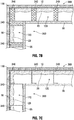
- Figure 7A is a top view cross-section of one embodiment of the frame and backing as joined to another embodiment of the frame and backing. As shown, two hollow partitions 140 contact each other. Also shown is interior air cavity 120 formed between solid backing 95 and polyurethane or structural foam 20. Further illustrated is vapor barrier 110 as applied to the exterior solid backing 10. As shown, the two partitions 140 may be hollow steel frames.
- Figure 7B is a top view cross-section of one embodiment of the frame and backing as joined to another embodiment of the frame and backing. As shown, two partitions 240 contact each other. Also shown is interior air cavity 120 formed between solid backing 95 and polyurethane or structural foam 20. Further illustrated is vapor barrier 110 as applied to the exterior solid backing 10. As shown, the two partitions 240 may be solid wood frames.
- Figure 7C is a top view cross-section of one embodiment of the frame and backing as joined to another embodiment of the frame and backing. As shown two partitions 340 contact each other. Also shown is interior air cavity 120 formed between solid backing 95 and polyurethane or structural foam 20. Further illustrated is vapor barrier 110 as applied to the exterior solid backing 10. As shown the two partitions 340 may be C channels.
- Figure 8 is an angled top view of one embodiment of the frame and backing of the present invention with all cells of the frame and backing with electrical equipment attached as well as horizontal cabling.
- electrical equipment 60, 70 and wiring 50 can be attached to the frame structure 30 or the partition beams 40.
- the electrical equipment 60, 70, and wiring 50 are not in physical contact with the polyurethane or structural foam 20.
- cable 500 has no physical contact with the polyurethane or structural foam 20. In some embodiments, it is envisioned that there can be some contact with foam 20 and cable 500.
- interior solid backing 95 has a solid backing 95 which can be comprised of wood, metal, composite material or other construction materials utilized for the construction of a wall face.
- solid backing 95 may be constructed of moisture resistant materials.
- solid backing 95 may be constructed of heat resistant and/or flame-retardant materials.
- solid backing 95 may be constructed of enhanced materials with increased tensile and modular strength.
- solid backing 95 may be a lightweight cement tile backerboard.
- solid backing 95 is water durable and composed of a mold-resistant substrate.
- solid backing 95 is non-combustible. In some embodiments, solid backing 95 mitigates blasts and explosions.
- Cable 500 may be composed of a material capable of tensioning and/or lifting a wall section 100 weighing at least 75 lbs.
- cable 500 is equipped with eyelets, or other attachments surfaces 535 and 545 at the ends of cable 500 capable of being pulled to tension or support cable 500 as it loops through the interior of wall section 100.
- cable 500 can substantially enter the wall section 100 through ports 540 and 550.
- cable 500 can loop through partition beams 40 and exit/reenter the wall section 100.
- cable 500 will traverse the entirety of wall section 100 in order to provide maximum support for wall section 100 when cable 500 is pulled to tension.
- cable 500 can enter and exit wall section 100 in various locations on frame structure 30.
- cable 500 is of sufficient strength to allow for either tensioning of wall section 100 with another section or lifting wall unit 100 off of the ground as done in construction work.
- cable 500 can be used and interface with the wall section 100, frame structure 30 or partition beams 40 at the top, bottom, or sides of the respective wall section 100, frame structure 30 or partition beams 40.
- cable 500 runs through the wall section 100 in two parallel lines 505 and 525. As shown cable 500 exits the wall section 100 at points 510 and 520, loops around the area of the wall section 100, distal to the eyelets 535 and 545. In some embodiments (not shown), the cable can pass through the partition beams 40 instead of the exterior of wall section 100.
- Figure 9 is an angled top view of one embodiment of the frame and backing of the present invention with all cells of the frame and backing with electrical equipment attached as well as vertical cabling.
- electrical equipment 60, 70 and wiring 50 can be attached to the frame structure 30 or the partition beams 40.
- the electrical equipment 60, 70, and wiring 50 are not in physical contact with the polyurethane or structural foam 20.
- Cable 600 may be composed of a material capable of tensioning and/or lifting a wall section 100.
- cable 600 is equipped with eyelets, or other attachments surfaces 635 and 645 at the ends of cable 600 capable of being pulled to tension or support cable 600 as it loops through the interior of wall section 100.
- cable 600 can substantially enter the wall section 100 through ports 640 and 650.
- cable 600 can loop through partition beams 40 at port 617 and exit the wall section 100.
- cable 600 will traverse a portion of wall section 100 in order to provide maximum support for wall section 100 when cable 600 is pulled to tension.
- cable 600 in some embodiments can enter wall section 100 through ports 640, then follow the path 605 through stud hole/port 610, then pathway 615 through stud hole/port 617, then through stud hole/port 620, and finally out of the wall section 100 through port 650.
- cable 600 can be used and interface with the wall section 100, frame structure 30 or partition beams 40 at the top, bottom, or sides of the respective wall section 100, frame structure 30 or partition beams 40.
- Cable 700 may be composed of a material capable of tensioning and/or lifting a wall section 100.
- cable 700 is equipped with eyelets, or other attachments surfaces 735 and 745 at the ends of cable 700 capable of being pulled to tension or support cable 700 as it loops through the interior of wall section 100.
- cable 700 can substantially enter the wall section 100 through ports 740 and 750.
- cable 700 can loop through partition beams 40 at port 717 and exit the wall section 100.
- cable 700 will traverse a portion of wall section 100 in order to provide maximum support for wall section 100 when cable 700 is pulled to tension.
- cable 700 can be used and interface with the wall section 100, frame structure 30 or partition beams 40 at the top, bottom, or sides of the respective wall section 100, frame structure 30 or partition beams 40
- cable 700 in some embodiments can enter wall section 100 through ports 740, then follow the path 705 through stud hole/port 710, then pathway 715 through stud hole/port 717, then through stud hole/port 720, and finally out of the wall section 100 through port 750.
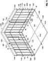
- Figure 10 is an angled top view of one embodiment of the frame and backing of the present invention with all cells of the frame and backing with electrical equipment attached as well as horizontal and vertical cabling.
- electrical equipment 60, 70 and wiring 50 can be attached to the frame structure 30 or the partition beams 40.
- the electrical equipment 60, 70, and wiring 50 are not in physical contact with the polyurethane or structural foam 20.
- Fig. 10 illustrates an alternate embodiment of the present invention in which at least four support cables are used.
- cable system 800 is preferably constructed with an eyelet 805 or attachment mechanism located at one end, and eyelet 825 located at the end distal for eyelet 805.
- cable 810 can enter wall section 100 through orifice 815, traverse the interior of wall section 100, and exit from outlet 820.
- cable 800 can be used and interface with the wall section 100, frame structure 30 or partition beams 40 at the top, bottom, or sides of the respective wall section 100, frame structure 30 or partition beams 40.
- Fig. 10 illustrates an alternate embodiment of the present invention in which at least four support cables are used.
- cable system 900 is preferably constructed with an eyelet 905 or attachment mechanism located at one end, and eyelet 925 located at the end distal for eyelet 905.
- cable 910 can enter wall section 100 through orifice 915, traverse the interior of wall section 100, and exit from outlet 920.
- cable 900 can be used and interface with the wall section 100, frame structure 30 or partition beams 40 at the top, bottom, or sides of the respective wall section 100, frame structure 30 or partition beams 40.
- Fig. 10 illustrates an alternate embodiment of the present invention in which at least four support cables are used.
- cable system 1100 is preferably constructed with an eyelet 1105 or attachment mechanism located at one end and eyelet 1125 located at the end distal for eyelet 1105.
- cable 1110 can enter wall section 100 through orifice 1115, traverse the interior of wall section 100, and exit from outlet 1120.
- cable 1110 can penetrate and traverse partition beams 40 at various intervals.
- cable 1100 can be used and interface with the wall section 100, frame structure 30 or partition beams 40 at the top, bottom, or sides of the respective wall section 100, frame structure 30 or partition beams 40.
- Fig. 10 illustrates an alternate embodiment of the present invention in which at least four support cables are used.
- cable system 1200 is preferably constructed with an eyelet 1205 or attachment mechanism located at one end, and eyelet 1225 located at the end distal for eyelet 1205.
- cable 1210 can enter wall section 100 through orifice 1215, traverse the interior of wall section 100 and exit from outlet 1220.
- cable 1210 can penetrate and traverse partition beams 40 at various intervals.
- cable 1200 can be used and interface with the wall section 100, frame structure 30 or partition beams 40 at the top, bottom, or sides of the respective wall section 100, frame structure 30 or partition beams 40.
- Figure 11 is a partially angled view of one embodiment of the present invention as assembled as a wall juncture with tethering to a floor.
- wall section 100 is attached to flooring unit 1500.
- Flooring unit 1500 can be another wall unit 100 scaled for use as a floor, or, as shown, a concrete slab 1510.
- concrete slab 1510 has cabling 1540 and 1550 traversing the interior of concrete slab 1510.
- cabling 1540 and 1550 have eyelets 1505 and 1525.
- concrete slab 1510 does not need cabling 1540 or 1550 to traverse the entire concrete slab 1510.
- cables 810 traverse wall units 100 vertically.
- eyelets 825 can be secured to eyelets 1525 as are known in the art for cinching.
- trusses 1530 used to secure cables 810 via eyelets 805 when the invention is cinched or tightened.
- trusses 1530 are secured to C clamps 1540 for added stability.
- cables 1220 and 1120 which can traverse wall unit 100 horizontally.
- cables 1220 and 1120 can be mechanically engaged with multiple corresponding cables 1220 and 1120 through the locking of eyelets 1105 with eyelets 1125 and eyelets 1205 with eyelets 1225 respectively.
Landscapes
- Engineering & Computer Science (AREA)
- Architecture (AREA)
- Civil Engineering (AREA)
- Structural Engineering (AREA)
- Physics & Mathematics (AREA)
- Electromagnetism (AREA)
- Life Sciences & Earth Sciences (AREA)
- Wood Science & Technology (AREA)
- Mechanical Engineering (AREA)
- Building Environments (AREA)
Abstract
Description
- This patent application claims priority to
US Patent Applications 15/883,617 15/883,681 - Not applicable.
- The present invention generally relates to the use of polyurethane foams in a pourable application for use in making prefabricated building materials in order to provide increased strength, durability and safety while at the same time improving production time as well as minimizing waste. A building component utilizing a pourable polyurethane foam that can be used as a structural polyurethane foam for floors, walls, and roof assemblies with a frame with an interior, back and a front, multiple partition beams forming cells in said frame, pourable polyurethane foam exterior backing attached to said frame back. The polyurethane is poured into said cells to a desired level, and after said polyurethane is poured into said cells, said interior backing is attached to said frame front. The present invention also generally relates to the use of cabling to improve movability of the invention, wind loading and seismic requirements. The present invention also generally relates to the use of cabling to tie down wall elements and pieces.
- The present invention is distinguished from the following art in many ways:
-
US 4,327,529 to Bigelow discloses a prefabricated building. The present invention involves the use of a pourable polyurethane foam not disclosed in Bigelow. -
US 4,470,227 to Bigelow discloses a building core. The present invention involves the use of a pourable polyurethane foam not disclosed in Bigelow. -
US 4,574,533 to Bigelow discloses a portable home. The present invention involves the use of a pourable polyurethane foam not disclosed in Bigelow. -
US 4,637,179 to Bigelow discloses a knockdown building. The present invention involves the use of a pourable polyurethane foam not disclosed in Bigelow. -
US 5,491,934 to Bigelow discloses a two-story building collapsed for shipping. The present invention involves the use of a pourable polyurethane foam not disclosed in Bigelow. -
US 5,864,992 to Bigelow discloses a roof and portable building. The present invention involves the use of a pourable polyurethane foam not disclosed in Bigelow. -
US 6,085,470 to Bigelow discloses a portable building. The present invention involves the use of a pourable polyurethane foam not disclosed in Bigelow. -
US 6,088,969 to Bigelow discloses a roof and portable building. The present invention involves the use of a pourable polyurethane foam not disclosed in Bigelow. -
US 6,240,684 to Bigelow discloses a portable automotive service building. The present invention involves the use of a pourable polyurethane foam not disclosed in Bigelow. -
US 6,295,766 to Bigelow discloses a prefabricated building. The present invention involves the use of a pourable polyurethane foam not disclosed in Bigelow. -
US 6,332,298 to Bigelow discloses a portable building construction. The present invention involves the use of a pourable polyurethane foam not disclosed in Bigelow. -
US 6,341,468 to Bigelow discloses a building with an attic module. The present invention involves the use of a pourable polyurethane foam not disclosed in Bigelow. -
US 6,862,847 to Bigelow discloses a prefabricated building. The present invention involves the use of a pourable polyurethane foam not disclosed in Bigelow. -
US 3,963,395 to Bourdo discloses a mass production line for fabricating structural building members. The present invention involves the use of a pourable polyurethane foam not disclosed in Bourdo. -
US 5,371,990 to SalahUddin discloses element-based foam and concrete modular wall construction and method apparatus therefor. The present invention involves the use of a pourable polyurethane foam not disclosed in SalahUddin. -
US 5,649,401 to Harrington, Jr. discloses a foam and channel concrete form system. The present invention involves the use of a pourable polyurethane foam not disclosed in Harrington, Jr. -
US 5,921,046 to Hammond, Jr. discloses a prefabricated building system for walls, roofs, and floors using a foam core building panel and connectors. The present invention involves the use of a pourable polyurethane foam not disclosed in Hammond, Jr. -
US 6,332,304 to Fuhrman discloses housing panels, encapsulated, with steel frames. The present invention involves the use of a pourable polyurethane foam not disclosed in Fuhrman. -
US 6,630,249 to Kennedy discloses composite steel structural plastic sandwich plate systems. The present invention involves the use of a pourable polyurethane foam not disclosed in Kennedy. -
US 6,703,331 to Bruce discloses a fungus resistant gypsum-based substrate. The present invention involves the use of a pourable polyurethane foam not disclosed in Bruce. -
US 6,729,094 to Spencer, et al. discloses pre-fabricated building panels and method of manufacture. The present invention involves the use of a pourable polyurethane foam not disclosed in Spencer, et al. -
US 8,613,172 to Olson, et al. discloses a composite panel including pre-stressed concrete with support frame, and method for making same. The present invention involves the use of a pourable polyurethane foam not disclosed in Olson, et al. -
US 8,877,329 to Ciuperca discloses high performance, highly energy efficient precast composite insulated concrete panels. The present invention involves the use of a pourable polyurethane foam not disclosed in Ciuperca. -
US 2002/0014051 to Fraval, et al. discloses a high strength lightweight fiber ash composite material, method of manufacture thereof and prefabricated structural building members using the same. The present invention involves the use of a pourable polyurethane foam not disclosed in Fraval, et al. -
US 2004/0111997 to Gigiakos discloses an apparatus and method for fabricating foam wall panels. The present invention involves the use of a pourable polyurethane foam not disclosed in Gigiakos. -
US 2005/0000178 to Rodgers, et al. discloses poured-in-place concrete construction components and method of construction. The present invention involves the use of a pourable polyurethane foam not disclosed in Rodgers, et al. -
US 2006/0174572 to Tonyan, et al. discloses non-combustible reinforced cementitious lightweight panels and metal frame system for shear walls. The present invention involves the use of a pourable polyurethane foam not disclosed in Tonyan, et al. -
US 2006/0185267 to Tonyan, et al. discloses non-combustible reinforced cementitious lightweight panels and metal frame system for roofing. The present invention involves the use of a pourable polyurethane foam not disclosed in Tonyan, et al. -
US 2007/0094992 to Antonic discloses structural wall panel assemblies. The present invention involves the use of a pourable polyurethane foam not disclosed in Antonic. -
US 2007/0245660 to Scott, et al. discloses wall construction system and method. The present invention involves the use of a pourable polyurethane foam not disclosed in Scott, et al. -
US 2008/0134589 to Abrams, et al. discloses a system for modular building construction. The present invention involves the use of a pourable polyurethane foam not disclosed in Abrams, et al. -
US 2008/0295425 to Farag discloses a panel-sealing and securing system. The present invention involves the use of a pourable polyurethane foam not disclosed in Farag. -
US 2009/0293280 to Gharibeh, et al. discloses a method of making a composite building panel. The present invention involves the use of a pourable polyurethane foam not disclosed in Gharibeh, et al. -
US 2013/0074432 to Ciuperca discloses an insulated concrete form and method of using same. The present invention involves the use of a pourable polyurethane foam not disclosed in Ciuperca. -
US 2014/0059961 to Yin, et al. discloses prefabricated thermal insulating composite panel, assembly thereof, molded panel and concrete slab comprising same method and mold profile for prefabricating same. The present invention involves the use of a pourable polyurethane foam not disclosed in Yin, et al. -
US 2014/0115988 to Sievers, et al. discloses a prefabricated wall assembly having an insulation foam layer. The present invention involves the use of a pourable polyurethane foam not disclosed in Sievers, et al. -
US 2009/0056258 to Currier discloses a forming apparatus system. The present invention involves the use of a pourable polyurethane foam and cable not disclosed in Currier. -
US 9,428,901 to Price -
US 7,727,446 to Wolfe discloses a concrete floor manufacturing station. The present invention involves the use of a pourable polyurethane foam and cable not disclosed in Wolfe. -
US 6,698,710 to VanderWerf discloses a forming apparatus system. The present invention involves the use of a pourable polyurethane foam and cable not disclosed in VanderWerf - The present invention is generally a building framework that can be insulated with a pourable structural foam that can be used as a structural polyurethane foam for floors, walls, ceiling, roof, or other structural assemblies. In some embodiments, the present invention allows for a consistent level of polyurethane, or structural foam materials for structural uses via the use of a pouring technique. In several embodiments, the present invention eliminates polyurethane or structural foam waste as found in spray and injection methods of applying polyurethane because in the present invention the polyurethane foam is poured. In several embodiments of the present invention, the pouring of the polyurethane or structural foam materials allows the materials to spread in a cell which increases surface area contact with the polyurethane or structural foam and the frame or partition beams. This also allows for self-leveling of the polyurethane or structural foam as well as elimination of air or gas pockets found in spray on polyurethanes and structural foams. In several embodiments of the present invention, the present invention uses cabling to improve movability of the invention, wind loading and seismic requirements. In several embodiments, the present invention uses cabling to tie down wall elements and pieces.
- In several embodiments, the present invention eliminates polyurethane overspray as found in spray methods of applying polyurethane. In several embodiments, the present invention eliminates shaving and/or trimming of excess polyurethane materials as found in spray and injection methods of applying polyurethane. In several embodiments of the present invention, expensive air filtration and process equipment are eliminated from use in application. In several embodiments of the present invention, the polyurethane or structural foam can be poured using mechanical or manual methods into cells. In several embodiments of the present invention, the polyurethane or structural foam is slow setting with a slower cure time therein allowing for the polyurethane or structural foam to self-level off after being poured into cells.
- In some embodiments, the bonding of the polyurethane to the frame structure of the present invention creates a monolithic structure with an increase in strength and thermal properties over the individual components. In several embodiments, the increase in strength would include, but not be limited to, tensile strength, wind loading, racking strength, sheer strength, and/or compressive strength, and combinations therein. In several embodiments, the monolithic structural nature of the module is created by the uniform bond of the polyurethane or structural foam because after it is cured it forms a uniform bond within the entire structure without any of the air or gas pocket gaps found in the nonpoured prior art polyurethane or structural foam applications.
- In many embodiments, the present invention provides increased fire ratings and thermal performance over other known building materials. In several embodiments, the polyurethane or structural foam is comprised of a Class 1 fire rated material. In several embodiments, the present invention's ballistic and blast mitigation may be achieved by incorporating various materials when pouring the foam. In several embodiments, these materials can include Nomex, nanobead ballistic pourable materials mixed with the polyurethane or structural foam, overcoating materials to apply after or before pouring the polyurethane structural foam, or other blast mitigating materials.
- In several embodiments, the present invention is comprised of components that are assembled with fire rated polyurethane foam and structural steel components. In several embodiments, the present invention is a structure that is impervious to rotting and/or deterioration from moisture.
- In several embodiments, the present invention is termite resistant. In several embodiments, the present invention completely eliminates the use of wood. In several embodiments, after a catastrophic event, the present invention eliminates the need to remove insulation due to flooding. In several embodiments, the present invention minimizes repairs in case of flooding.
- In several embodiments, the assembly of components of the present invention is achieved in a process where polyurethane or structural foam and/or a similar composite is poured into the structure to strengthen the assembly for various loads, which include, but are not limited to: wind, compression, sheer, and tensile strength. In several embodiments, the polyurethane or structural foam can be poured into a frame cell individually, or into many cells at once.
- In several embodiments, the pouring of the polyurethane materials in a precise manner allows for electrical and/or plumbing to be run inside a wall between the interior surface and the cavity created between the insulation and interior finished surface. This method of assembly allows for a closed wall panelized system. In several embodiments of the present invention, the polyurethane or structural foam is a dense cellular plastic material designed to retard moisture.
- In several embodiments, the present invention can be used for walls, roofs and floor sheeting comprised of non-wood material.
- In several embodiments, cables, or cabling, will be added to the wall, floor and roof systems during manufacturing and may remain in the components after assembly. In several embodiments, cables, or cabling can run vertically and/or horizontally through the wall components of the invention. In several embodiments, cables, or cabling can be used to connect the wall, floor and roof together for wind loading and/or seismic requirements. In some embodiments, cables, or cabling included in wall, floor and roof system maybe used to tie components to the foundation whether it is a concrete slab, piers, grade beam, blocks, or the like. In some embodiments, cables or cabling systems are used for safety in lifting and handling the components during the manufacturing process, loading, unloading and assembly.
- In some embodiments, the present invention is a building component utilizing a pourable polyurethane or structural foam that can be used as a structural polyurethane or structural foam for floors, walls, and roof assemblies comprising: a frame with an interior, back and a front; multiple partition beams forming cells in said frame; pourable polyurethane foam; exterior backing attached to said frame back; and interior backing; wherein said polyurethane is poured into said cells to a desired level, and after said polyurethane is poured into said cells, said interior backing is attached to said frame front.
- In some embodiments, the present invention of the pourable polyurethane or structural foam has increased thermal properties which include increased fire ratings and thermal performance. In some embodiments, the pourable polyurethane or structural foam has ballistic and blast mitigation by incorporating various materials when pouring said polyurethane foam. In some embodiments, the frame is comprised of a structural steel component. In several embodiments, the pourable polyurethane or structural foam is moisture resistant. In several embodiments, electrical equipment is attached to said frame interior prior to attaching said interior backing to said frame front. In several embodiments, the electrical equipment is installed to said frame interior without contact to said pourable polyurethane foam.
- In several embodiments, the present invention is a building component utilizing a pourable structural foam that can be used as a structural polyurethane or structural foam for floors, walls, ceiling and roof assemblies comprising: a bonding polyurethane that adheres to the frame structure with an interior portion creating a monolithic structure with an increase in strength and thermal properties, with said strength increasing properties including, but not limited, to tensile strength, wind loading strength, racking strength, sheer strength, and/or compressive strength, and combinations therein; and a cable located partially outside of said frame structure and traversing at least an interior portion of said frame structure. In several embodiments, the cable is comprised of multiple cables. In several embodiments, the multiple cables can intersect each other through said frame.
- In several embodiments, the present invention is a building component utilizing a pourable structural foam that can be used as a structural foam for floors, walls, ceiling and roof assemblies comprising: a frame with an interior, back and a front; multiple partition beams forming cells in said frame; pourable structural foam; exterior backing attached to said frame back; and interior backing; a cable located partially outside of said frame structure and traversing at least an interior portion of said frame structure; wherein said structural foam is poured into said cells to a desired level and after said structural foam is poured into said cells said interior backing is attached to said frame front. In several embodiments, the cable is comprised of multiple cables. In several embodiments, the multiple cables can intersect each other through said frame.
- For a more complete understanding of the present disclosure and the advantages thereof, reference is now made to the following descriptions to be taken in conjunction with the accompanying drawings describing specific embodiments of the disclosure, wherein:
-
Figure 1 is a partially angled view of one embodiment of the present invention as assembled as a wall juncture. -
Figure 2 is an angled top view of one embodiment of the frame and backing of the present invention. -
Figure 3A is an angled top view of one embodiment of the frame and backing of the present invention with filler/adhesive material being added to one cell of the frame and backing. -
Figure 3B is a variant of one embodiment of the polyurethane pouring tube of the present invention. -
Figure 4 is an angled top view of one embodiment of the frame and backing of the present invention with filler/adhesive material being added to multiple cells of the frame and backing. -
Figure 5 is an angled top view of one embodiment of the frame and backing of the present invention with all cells of the frame and backing with electrical equipment attached. -
Figure 6 is an angled top cross-sectional view of one embodiment of the frame with front and rear backing of the present invention with all cells of the frame filled with polyurethane or structural foam and electrical wiring is attached. -
Figure 7A is a top view cross-section of one embodiment of the frame and backing as joined to another embodiment of the frame and backing. -
Figure 7B is a top view cross-section of one embodiment of the frame and backing as joined to another embodiment of the frame and backing. -
Figure 7C is a top view cross-section of one embodiment of the frame and backing as joined to another embodiment of the frame and backing. -
Figure 8 is an angled top view of one embodiment of the frame and backing of the present invention with all cells of the frame and backing with electrical equipment attached as well as horizontal cabling. -
Figure 9 is an angled top view of one embodiment of the frame and backing of the present invention with all cells of the frame and backing with electrical equipment attached as well as vertical cabling. -
Figure 10 is an angled top view of one embodiment of the frame and backing of the present invention with all cells of the frame and backing with electrical equipment attached as well as horizontal and vertical cabling. -
Figure 11a partially angled view of one embodiment of the present invention as assembled as a wall juncture with tethering to a floor. - One or more illustrative embodiments incorporating the invention disclosed herein are presented below. Applicant has created a revolutionary and novel wall, roof, and floor design with pourable polyurethane or structural foam insulation with cabling to improve movability of the invention, wind loading and seismic requirements. The cable can be comprised of multiple cables. Multiple cables can intersect each other through said frame.
- In the following description, certain details are set forth such as specific quantities, sizes, etc. so as to provide a thorough understanding of the present embodiments disclosed herein. However, it will be evident to those of ordinary skill in the art that the present disclosure may be practiced without such specific details. In many cases, details concerning such considerations and the like have been omitted inasmuch as such details are not necessary to obtain a complete understanding of the present disclosure and are within the skills of persons of ordinary skill in the relevant art.
- Referring to the drawings in general, it will be understood that the illustrations are for the purpose of describing particular embodiments of the disclosure and are not intended to be limiting thereto. Drawings are not necessarily to scale and arrangements of specific units in the drawings can vary.
- While most of the terms used herein will be recognizable to those of ordinary skill in the art, it should be understood, however, that when not explicitly defined, terms should be interpreted as adopting a meaning presently accepted by those of ordinary skill in the art. In cases where the construction of a term would render it meaningless or essentially meaningless, the definition should be taken from Webster's Dictionary, New Edition, 2016. Definitions and/or interpretations should not be incorporated from other patent applications, patents, or publications, related or not, unless specifically stated in this specification or if the incorporation is necessary for maintaining validity. Specifically, defined terms: the term "wall module" means any structural component which can be used as a wall, floor, roof, ceiling or a solid barrier construction. As utilized herein, "wall modules" can be portable or permanent structures. As utilized herein, the "frame" and the "partition barriers" can be defined to be any three-dimensional structures used in construction for a solid barrier. "Electrical Equipment" as defined herein can include, but is not limited to, electrical wiring, plumbing chases, air space, ducting, and other materials normally associated with the spaces between interior and exterior wall faces. "Cable" or "cabling" as defined herein can include, but is not limited to, a thick rope of wire, nonmetallic fiber, or other material typically used for construction. In several embodiments, the "Cable" or "cabling" can be steel, nylon, rope, strap materials or binding material. The terms "bottom", "top", and "side" as used herein are relative to each other, in that "bottom" is parallel to "top" and a "side" is parallel to another "side". In several embodiments of the present invention, a "bottom" can be perpendicular to the ground, or even located a further distance from the ground than a "top". The term "eyelet" as used herein can be a construction eyelet, loop in a cable, clamp, loop on a hook, shackle, clevis, or other attachment as used in construction.
- In many embodiments components can be rotated, moved laterally, moved horizontally, or moved in relationship to each other.
- Certain terms are used in the following description and claims to refer to particular system components. As one skilled in the art will appreciate, different persons may refer to a component by different names. This document does not intend to distinguish between components that differ in name but not function. The drawing figures are not necessarily to scale. Certain features of the invention may be shown exaggerated in scale or in somewhat schematic form, and some details of conventional elements may not be shown, all in the interest of clarity and conciseness.
- Although several preferred embodiments of the present invention have been described in detail herein, the invention is not limited hereto. It will be appreciated by those having ordinary skill in the art that various modifications can be made without materially departing from the novel and advantageous teachings of the invention. Accordingly, the embodiments disclosed herein are by way of example. It is to be understood that the scope of the invention is not to be limited thereby.
-
Figure 1 is a partially angled view of one embodiment of the present invention as assembled as awall juncture 400. Thejuncture 7 is the focus ofFig. 7A-C . As shown, the present invention is pourable polyurethane orstructural foam 20 used as a structural polyurethane or structural foam for floors, walls, and roof assemblies, as shown inFigure 1 ,wall module 100. In some embodiments, the pourable polyurethane orstructural foam 20 can be a two-part rigid polyurethane or structural foam system. In some embodiments, polyurethane orstructural foam 20 can bond multiple non-porous surfaces, porous surfaces, or combinations therein. In some embodiments, polyurethane foam is an all-weather use foam. In some embodiments, polyurethane orstructural foam 20 can be applied in temperatures ranging from 40-140°F. In some embodiments, polyurethane orstructural foam 20 is fire retardant when dry. In several embodiments, the polyurethane or structural foam is comprised of a Class 1 fire rated material. In some embodiments, polyurethane orstructural foam 20 is mold and water damage resistant. - As shown,
wall module 100 generally has aninterior face 200 and anouter face 300. Eachwall module 100 could also function as a ceiling or floor module in application. In many embodiments,outer face 300 can be the face of the wall closest to the outside of a structure. In many embodiments,outer face 300 has asolid backing 10 which can be comprised of wood, metal, composite material or other construction materials utilized for the construction of a wall face. In several embodiments,solid backing 10 may be constructed of moisture resistant materials. In several embodiments of the present invention, the polyurethane or structural foam is a dense cellular plastic material designed to retard moisture. In several embodiments,solid backing 10 may be constructed of heat resistant and/or flame-retardant materials. - In several embodiments,
solid backing 10 may be constructed of enhanced materials with increased tensile and modular strength. In several embodiments, the monolithic structural nature of the module is created by the uniform bond of the polyurethane orstructural foam 20 because after it is cured it forms a uniform bond within the entire structure without any of the air or gas pocket gaps found in the nonpoured prior art polyurethane or structural foam applications. In several embodiments, (Fig. 7A-C )solid backing 10 can be coated with avapor barrier 110. In some embodiments, backing 10 may be a lightweight cement tile backerboard. In some embodiments, backing 10 is water durable and composed of a mold-resistant substrate. In some embodiments, backing 10 is non-combustible. In some embodiments, backing 10 mitigates blasts and explosions. In several embodiments, these materials can include Nomex, nanobead ballistic pourable materials mixed with the polyurethane orstructural foam 20, overcoating materials to apply after or before pouring the polyurethane orstructural foam 20, or other blast mitigating materials. - As shown,
solid backing 10 is preferably attached to aframe 30.Frame 30 can be comprised of wood, metal, composite material or other construction materials utilized for the construction of a wall frame. In several embodiments,frame 30 maybe constructed of moisture resistant materials. In several embodiments,frame 30 may be constructed of heat resistant and/or flame-retardant materials. In several embodiments,frame 30 may be constructed of enhanced materials with increased tensile and modular strength. The geometric shape offrame 30 can vary per user needs. In some embodiments,frame 30 is water durable and composed of a mold-resistant substrate. In some embodiments,frame 30 is non-combustible. This aspect of the present invention is of economic and material benefit to any end user over the prior art. In some embodiments,frame 30 mitigates blasts and explosions by using Nomex, nanobead ballistic pourable materials mixed with the polyurethane orstructural foam 20, overcoating materials to apply after or before pouring the polyurethane orstructural foam 20, or other blast mitigating materials. - As shown, separating
frame 30 into various cells 26 (Fig 3A ) are partition beams 40. Partition beams 40 can be comprised of wood, metal, composite material or other construction materials utilized for the construction of a wall frame. In several embodiments, partition beams 40 may be constructed of moisture resistant materials. In several embodiments, partition beams 40 may be constructed of heat resistant and/or flame-retardant materials. In several embodiments, partition beams 40 may be constructed of enhanced materials with increased tensile and modular strength. The geometric shape ofpartition beams 40 can vary per user needs. In some embodiments, partition beams 40 are water durable and composed of a mold-resistant substrate. In some embodiments, partition beams 40 are non-combustible. In some embodiments, partition beams 40 mitigate blasts and explosions. This aspect of the present invention is of economic and material benefit to any end user over the prior art. In several embodiments, partition beams 40 andframe 30 are assembled together as is known in the art. - As shown, between partition beams 40 is pourable polyurethane or
structural foam 20. In some embodiments, the present invention allows for a consistent level of polyurethane orstructural foam 20 for structural uses. In several embodiments, the present invention eliminates polyurethane orstructural foam 20 waste as found in spray and injection methods of applying polyurethane as known in previous art. In several embodiments, the present invention eliminates polyurethane overspray as found in spray methods of applying polyurethane. In several embodiments, the present invention eliminates shaving and/or trimming of excess polyurethane materials as found in spray and injection methods of applying polyurethane. This aspect of the present invention is of economic and material benefit to any end user over the prior art. - In several embodiments of the present invention, expensive air filtration and process equipment are eliminated from use in application of the polyurethane or
structural foam 20. In some embodiments, the bonding of the polyurethane orstructural foam 20 to theframe structure 30 creates a monolithic structure with an increase in strength and thermal properties over the individual components. In several embodiments, the increase in strength ofwall module 100 would include, but not be limited to, tensile strength, wind loading, racking strength, sheer strength, and/or compressive strength, and combinations therein. This aspect of the present invention is of economic and material benefit to any end user over the prior art. In several embodiments of the present invention, the polyurethane orstructural foam 20 can be poured using mechanical or manual methods into cells 26 (SeeFig. 2 ). In several embodiments of the present invention, the polyurethane orstructural foam 20 is slow setting with a slower cure time therein allowing for the polyurethane orstructural foam 20 to self-level off after being poured into cells 26 (Fig. 2 ). - In several embodiments of the present invention, the polyurethane or
structural foam 20 can adhere to the partition beams 40 at interfaces 25.Interfaces 25, the bonding of the polyurethane orstructural foam 20 to theframe structure 30, creates a monolithic structure with an increase in strength and thermal properties over the individual components. - In several embodiments,
electrical equipment wiring 50 can be attached to theframe structure 30 or the partition beams 40. In many embodiments of the present invention, theelectrical equipment wiring 50 are not in physical contact with the polyurethane orstructural foam 20. Since theelectrical equipment wiring 50 is not in contact with the polyurethane orstructural foam 20, this means that that repair or replacement of theelectrical equipment wiring 50 does not require destruction, movement or manipulation of the polyurethane orstructural foam 20. This aspect of the present invention is of economic and material benefit to any end user over the prior art. -
Figure 2 is an angled top view of one embodiment of the frame and backing of the present invention. As shown,solid backing 10 is preferably attached to aframe 30. As shown, separatingframe 30 intovarious cells 26 are partition beams 40. As shown,wall module 100 generally has aninterior face 200 and anouter face 300. Eachwall module 100 could also function as a ceiling or floor module in application. In many embodiments,outer face 300 can be the face of the wall closest to the outside of a structure. In many embodiments,outer face 300 has asolid backing 10. In several embodiments,solid backing 10 is lightweight. -
Figure 3A is an angled top view of one embodiment of the frame and backing of the present invention with polyurethane orstructural foam 20 being poured into a cell. As shown,solid backing 10 is preferably attached to aframe 30. Thesolid backing 10 can be attached to frame 30 in a manner known in the art. As shown, separatingframe 30 intovarious cells 26 are partition beams 40. In several embodiments, it is preferred to have the polyurethane orstructural foam 20 poured when theframe 30 is flat against a surface. In several embodiments of the present invention, the pouring of the polyurethane orstructural foam 20 materials allows the materials to spread in a cell which increases surface area contact with the polyurethane orstructural foam 20 and theframe 30 or partition beams 40. This also allows for self-leveling of the polyurethane orstructural foam 20 as well as elimination of air or gas pockets found in spray on polyurethanes and structural foams. - As shown,
wall module 100 generally has aninterior face 200 and anouter face 300. Eachwall module 100 could also function as a ceiling or floor module in application. In many embodiments, eachwall module 100 can be used for a variety of applications in building structures. In many embodiments,outer face 300 can be the face of the wall closest to the outside of a structure. In many embodiments,outer face 300 has asolid backing 10. As shown, the polyurethane orstructural foam 20 is being poured intocell 26 by a stylized pouringtube 80. - As shown in
Fig. 3B , the pouringtube 80 may be configured with a centralhollow chamber 90 withvariant pouring nozzles 85. Thevariant pouring nozzles 85 can be of any number andhollow chamber 90 can be of any variant size to allow for the filling ofmultiple cells 26 at the same time with polyurethane orstructural foam 20. -
Figure 4 is an angled top view of one embodiment of the frame and backing of the present invention with polyurethane orstructural foam 20 being poured into acell 26. As shown,solid backing 10 is preferably attached to aframe 30. As shown, separatingframe 30 intovarious cells 26 are partition beams 40. In many embodiments,outer face 300 can be the face of the wall closest to the outside of a structure. In many embodiments,outer face 300 has asolid backing 10. As shown, the polyurethane orstructural foam 20 has been poured intocells 26 by a stylized pouringtube 80. In several embodiments of the present invention, the polyurethane orstructural foam 20 is poured into thecells 26 leaving a layer of space between the depth of theframe 30 and the partition beams 40 that is free of polyurethane orstructural foam 20. In several embodiments of the present invention, the pouring of the polyurethane orstructural foam 20 materials allows the materials to spread in a cell which increases surface area contact with the polyurethane orstructural foam 20 and theframe 30 or partition beams 40. This also allows for self-leveling of the polyurethane orstructural foam 20 as well as elimination of air or gas pockets found in spray on polyurethanes and structural foams. -
Figure 5 is an angled top view of one embodiment of the frame and backing of the present invention with all cells of the frame and backing with electrical equipment and/or wiring attached. In several embodiments,electrical equipment Fig. 1 ) can be attached to theframe structure 30 or the partition beams 40. In many embodiments of the present invention, theelectrical equipment Fig. 1 ) are not in physical contact with the polyurethane orstructural foam 20. -
Figure 6 is an angled top cross-sectional view of one embodiment of the frame with front and rear backing of the present invention with all cells of the frame filled and some electrical equipment and wiring attached. In several embodiments,electrical equipment Fig. 1 ) can be attached to theframe structure 30 or the partition beams 40. In many embodiments of the present invention, theelectrical equipment Fig. 1 ) are not in physical contact with the polyurethane orstructural foam 20. In several embodiments, interiorsolid backing 95 has asolid backing 95 which can be comprised of wood, metal, composite material or other construction materials utilized for the construction of a wall face. In several embodiments,solid backing 95 may be constructed of moisture resistant materials. In several embodiments,solid backing 95 may be constructed of heat resistant and/or flame-retardant materials. In several embodiments,solid backing 95 may be constructed of enhanced materials with increased tensile and modular strength. In some embodiments,solid backing 95 may be a lightweight cement tile backerboard. In some embodiments,solid backing 95 is water durable and composed of a mold-resistant substrate. In some embodiments,solid backing 95 is non-combustible. In some embodiments,solid backing 95 mitigates blasts and explosions. -
Figure 7A is a top view cross-section of one embodiment of the frame and backing as joined to another embodiment of the frame and backing. As shown, twohollow partitions 140 contact each other. Also shown isinterior air cavity 120 formed betweensolid backing 95 and polyurethane orstructural foam 20. Further illustrated isvapor barrier 110 as applied to the exteriorsolid backing 10. As shown, the twopartitions 140 may be hollow steel frames. -
Figure 7B is a top view cross-section of one embodiment of the frame and backing as joined to another embodiment of the frame and backing. As shown, twopartitions 240 contact each other. Also shown isinterior air cavity 120 formed betweensolid backing 95 and polyurethane orstructural foam 20. Further illustrated isvapor barrier 110 as applied to the exteriorsolid backing 10. As shown, the twopartitions 240 may be solid wood frames. -
Figure 7C is a top view cross-section of one embodiment of the frame and backing as joined to another embodiment of the frame and backing. As shown twopartitions 340 contact each other. Also shown isinterior air cavity 120 formed betweensolid backing 95 and polyurethane orstructural foam 20. Further illustrated isvapor barrier 110 as applied to the exteriorsolid backing 10. As shown the twopartitions 340 may be C channels. -
Figure 8 is an angled top view of one embodiment of the frame and backing of the present invention with all cells of the frame and backing with electrical equipment attached as well as horizontal cabling. In several embodiments,electrical equipment Fig. 1 ) can be attached to theframe structure 30 or the partition beams 40. In many embodiments of the present invention, theelectrical equipment Fig. 1 ) are not in physical contact with the polyurethane orstructural foam 20. In several embodiments,cable 500 has no physical contact with the polyurethane orstructural foam 20. In some embodiments, it is envisioned that there can be some contact withfoam 20 andcable 500. In several embodiments, interiorsolid backing 95 has asolid backing 95 which can be comprised of wood, metal, composite material or other construction materials utilized for the construction of a wall face. In several embodiments,solid backing 95 may be constructed of moisture resistant materials. In several embodiments,solid backing 95 may be constructed of heat resistant and/or flame-retardant materials. In several embodiments,solid backing 95 may be constructed of enhanced materials with increased tensile and modular strength. In some embodiments,solid backing 95 may be a lightweight cement tile backerboard. In some embodiments,solid backing 95 is water durable and composed of a mold-resistant substrate. In some embodiments,solid backing 95 is non-combustible. In some embodiments,solid backing 95 mitigates blasts and explosions. -
Cable 500 may be composed of a material capable of tensioning and/or lifting awall section 100 weighing at least 75 lbs. In several embodiments,cable 500 is equipped with eyelets, orother attachments surfaces cable 500 capable of being pulled to tension orsupport cable 500 as it loops through the interior ofwall section 100. As shown,cable 500 can substantially enter thewall section 100 throughports cable 500 can loop throughpartition beams 40 and exit/reenter thewall section 100. In many embodiments,cable 500 will traverse the entirety ofwall section 100 in order to provide maximum support forwall section 100 whencable 500 is pulled to tension. In many embodiments,cable 500 can enter andexit wall section 100 in various locations onframe structure 30. In several embodiments,cable 500 is of sufficient strength to allow for either tensioning ofwall section 100 with another section or liftingwall unit 100 off of the ground as done in construction work. In many embodiments,cable 500 can be used and interface with thewall section 100,frame structure 30 orpartition beams 40 at the top, bottom, or sides of therespective wall section 100,frame structure 30 or partition beams 40. - As shown, in some
embodiments cable 500 runs through thewall section 100 in twoparallel lines cable 500 exits thewall section 100 atpoints wall section 100, distal to theeyelets wall section 100. -
Figure 9 is an angled top view of one embodiment of the frame and backing of the present invention with all cells of the frame and backing with electrical equipment attached as well as vertical cabling. In several embodiments,electrical equipment Fig. 1 ) can be attached to theframe structure 30 or the partition beams 40. In many embodiments of the present invention, theelectrical equipment Fig. 1 ) are not in physical contact with the polyurethane orstructural foam 20. - Also shown is
cable 600.Cable 600 may be composed of a material capable of tensioning and/or lifting awall section 100. In several embodiments,cable 600 is equipped with eyelets, orother attachments surfaces cable 600 capable of being pulled to tension orsupport cable 600 as it loops through the interior ofwall section 100. As shown,cable 600 can substantially enter thewall section 100 throughports cable 600 can loop throughpartition beams 40 atport 617 and exit thewall section 100. In many embodiments,cable 600 will traverse a portion ofwall section 100 in order to provide maximum support forwall section 100 whencable 600 is pulled to tension. - As shown,
cable 600 in some embodiments can enterwall section 100 throughports 640, then follow thepath 605 through stud hole/port 610, thenpathway 615 through stud hole/port 617, then through stud hole/port 620, and finally out of thewall section 100 throughport 650. In many embodiments,cable 600 can be used and interface with thewall section 100,frame structure 30 orpartition beams 40 at the top, bottom, or sides of therespective wall section 100,frame structure 30 or partition beams 40. - Also shown is
cable 700.Cable 700 may be composed of a material capable of tensioning and/or lifting awall section 100. In several embodiments,cable 700 is equipped with eyelets, orother attachments surfaces cable 700 capable of being pulled to tension orsupport cable 700 as it loops through the interior ofwall section 100. As shown,cable 700 can substantially enter thewall section 100 throughports cable 700 can loop throughpartition beams 40 atport 717 and exit thewall section 100. In many embodiments,cable 700 will traverse a portion ofwall section 100 in order to provide maximum support forwall section 100 whencable 700 is pulled to tension. In many embodiments,cable 700 can be used and interface with thewall section 100,frame structure 30 orpartition beams 40 at the top, bottom, or sides of therespective wall section 100,frame structure 30 orpartition beams 40 - As shown,
cable 700 in some embodiments can enterwall section 100 throughports 740, then follow thepath 705 through stud hole/port 710, thenpathway 715 through stud hole/port 717, then through stud hole/port 720, and finally out of thewall section 100 throughport 750. -
Figure 10 is an angled top view of one embodiment of the frame and backing of the present invention with all cells of the frame and backing with electrical equipment attached as well as horizontal and vertical cabling. In several embodiments,electrical equipment Fig. 1 ) can be attached to theframe structure 30 or the partition beams 40. In many embodiments of the present invention, theelectrical equipment Fig. 1 ) are not in physical contact with the polyurethane orstructural foam 20. -
Fig. 10 illustrates an alternate embodiment of the present invention in which at least four support cables are used. As shown,cable system 800 is preferably constructed with aneyelet 805 or attachment mechanism located at one end, and eyelet 825 located at the end distal foreyelet 805. As shown,cable 810 can enterwall section 100 throughorifice 815, traverse the interior ofwall section 100, and exit fromoutlet 820. In many embodiments,cable 800 can be used and interface with thewall section 100,frame structure 30 orpartition beams 40 at the top, bottom, or sides of therespective wall section 100,frame structure 30 or partition beams 40. -
Fig. 10 illustrates an alternate embodiment of the present invention in which at least four support cables are used. As shown,cable system 900 is preferably constructed with aneyelet 905 or attachment mechanism located at one end, and eyelet 925 located at the end distal foreyelet 905. As shown,cable 910 can enterwall section 100 throughorifice 915, traverse the interior ofwall section 100, and exit fromoutlet 920. In many embodiments,cable 900 can be used and interface with thewall section 100,frame structure 30 orpartition beams 40 at the top, bottom, or sides of therespective wall section 100,frame structure 30 or partition beams 40. -
Fig. 10 illustrates an alternate embodiment of the present invention in which at least four support cables are used. As shown,cable system 1100 is preferably constructed with aneyelet 1105 or attachment mechanism located at one end andeyelet 1125 located at the end distal foreyelet 1105. As showncable 1110 can enterwall section 100 throughorifice 1115, traverse the interior ofwall section 100, and exit fromoutlet 1120. As shown,cable 1110 can penetrate and traversepartition beams 40 at various intervals. In many embodiments,cable 1100 can be used and interface with thewall section 100,frame structure 30 orpartition beams 40 at the top, bottom, or sides of therespective wall section 100,frame structure 30 or partition beams 40. -
Fig. 10 illustrates an alternate embodiment of the present invention in which at least four support cables are used. As shown,cable system 1200 is preferably constructed with aneyelet 1205 or attachment mechanism located at one end, andeyelet 1225 located at the end distal foreyelet 1205. As shown,cable 1210 can enterwall section 100 throughorifice 1215, traverse the interior ofwall section 100 and exit fromoutlet 1220. As showncable 1210 can penetrate and traversepartition beams 40 at various intervals. In many embodiments,cable 1200 can be used and interface with thewall section 100,frame structure 30 orpartition beams 40 at the top, bottom, or sides of therespective wall section 100,frame structure 30 or partition beams 40. -
Figure 11 is a partially angled view of one embodiment of the present invention as assembled as a wall juncture with tethering to a floor. As shown, in some embodiments,wall section 100 is attached toflooring unit 1500.Flooring unit 1500 can be anotherwall unit 100 scaled for use as a floor, or, as shown, aconcrete slab 1510. As shown,concrete slab 1510 has cabling 1540 and 1550 traversing the interior ofconcrete slab 1510. As shown,cabling eyelets concrete slab 1510 does not need cabling 1540 or 1550 to traverse the entireconcrete slab 1510. - As further shown,
cables 810traverse wall units 100 vertically. As shown, in this embodiment, eyelets 825 can be secured toeyelets 1525 as are known in the art for cinching. Further illustrated aretrusses 1530 used to securecables 810 viaeyelets 805 when the invention is cinched or tightened. As further shown, trusses 1530 are secured to C clamps 1540 for added stability. - Further illustrated are
cables wall unit 100 horizontally. In many embodiments,cables corresponding cables eyelets 1105 witheyelets 1125 andeyelets 1205 witheyelets 1225 respectively. - In several embodiments of the present invention, when all cables, 1540, 1550, 1220, 1120, and 810 are tightened, the entire structure is tightened and cinched, therein allowing for increased load capacity and seismic tolerances for the entirety of the
construct 2000. - While preferred embodiments have been shown and described, modifications thereof can be made by one skilled in the art without departing from the scope or teaching herein. The embodiments described herein are exemplary only and are not limiting. Many variations and modifications of the system and apparatus are possible and will become apparent to those skilled in the art once the above disclosure is fully appreciated. For example, the relative dimensions of various parts, the materials from which the various parts are made, and other parameters can be varied.
Claims (15)
- A building component utilizing a pourable structural foam that can be used as a structural polyurethane or structural foam for floors, walls, ceiling and roof assemblies comprising:a bonding polyurethane that adheres to the frame structure creating a monolithic structure with an increase in strength and thermal properties, with said strength increasing properties including, but not limited, to tensile strength, wind loading strength, racking strength, sheer strength, and/or compressive strength, and combinations therein.
- A building component utilizing a pourable structural foam that can be used as a structural foam for floors, walls, ceiling and roof assemblies comprising:a frame with an interior, back and a front;multiple partition beams forming cells in said frame;pourable structural foam;exterior backing attached to said frame back; andinterior backing; whereinsaid structural foam is poured into said cells to a desired level and after said structural foam is poured into said cells said interior backing is attached to said frame front.
- A building component utilizing a pourable structural foam that can be used as a structural polyurethane or structural foam for floors, walls, ceiling and roof assemblies comprising:a bonding polyurethane that adheres to the frame structure with and interior portion creating a monolithic structure with an increase in strength and thermal properties, with said strength increasing properties including, but not limited, to tensile strength, wind loading strength, racking strength, sheer strength, and/or compressive strength, and combinations therein; anda cable located partially outside of said frame structure and traversing at least an interior portion of said frame structure.
- A building component utilizing a pourable structural foam that can be used as a structural foam for floors, walls, ceiling and roof assemblies comprising:a frame with an interior, back and a front;multiple partition beams forming cells in said frame;pourable structural foam;exterior backing attached to said frame back; andinterior backing;a cable located partially outside of said frame structure and traversing at least an interior portion of said frame structure; whereinsaid structural foam is poured into said cells to a desired level and after said structural foam is poured into said cells said interior backing is attached to said frame front.
- The building component of claim 3 or claim 4 wherein said cable is comprised of multiple cables, and optionally wherein further said cables can intersect each other through said frame.
- The building component of any preceding claim in which at least one of the following applies:(i) said increased thermal properties include increased fire ratings and thermal performance; and(ii) ballistic and blast mitigation is achieved by incorporating various materials when pouring said structural foam.
- The building component of any preceding claim in which said frame is comprised of a structural steel component.
- The building component of any preceding claim in which said structural foam is at least one of:(i) moisture resistant; and(ii) a polyurethane foam.
- The building component of any preceding claim in which electrical equipment is attached to said frame interior prior to attaching said interior backing to said frame front, and wherein optionally said electrical equipment is installed to said frame interior without contact to said pourable structural foam.
- A method for making a building component utilizing a pourable structural foam that can be used as a structural foam for floors, walls, and roof assemblies comprising the steps of:obtaining a frame with an interior, back and a front;securing multiple partition beams forming cells in said frame;obtaining pourable structural foam;attaching an exterior backing to said frame back;obtaining an interior backing; andpouring said structural foam into said cells to a desired level, and after said structural foam is poured into said cells attaching said interior backing to said frame front.
- The method of claim 10 in which at least one of the following applies:(i) said increased thermal properties include increased fire ratings and thermal performance; and(ii) ballistic and blast mitigation is achieved by incorporating various materials when pouring said structural foam;.
- The method of claim 10 or claim 11 in which said frame is comprised of a structural steel component.
- The method of any of claims 10 to 12 in which said foam is moisture resistant.
- The method of any of claims 10 to 13 in which said foam is polyurethane.
- The method of any of claims 10 to 14 further comprising the steps of:attaching electrical equipment to said frame interior prior to attaching said interior backing to said frame front, and optionally further comprising:installing said electrical equipment to said frame interior without contact to said pourable structural foam.
Priority Applications (1)
| Application Number | Priority Date | Filing Date | Title |
|---|---|---|---|
| US16/244,691 US10683661B2 (en) | 2018-01-30 | 2019-01-10 | Building module with pourable foam and cable |
Applications Claiming Priority (2)
| Application Number | Priority Date | Filing Date | Title |
|---|---|---|---|
| US201815883617A | 2018-01-30 | 2018-01-30 | |
| US201815883681A | 2018-01-30 | 2018-01-30 |
Publications (1)
| Publication Number | Publication Date |
|---|---|
| EP3517701A1 true EP3517701A1 (en) | 2019-07-31 |
Family
ID=61581065
Family Applications (1)
| Application Number | Title | Priority Date | Filing Date |
|---|---|---|---|
| EP18160349.9A Withdrawn EP3517701A1 (en) | 2018-01-30 | 2018-03-06 | Improved building module with pourable foam and cable |
Country Status (1)
| Country | Link |
|---|---|
| EP (1) | EP3517701A1 (en) |
Cited By (1)
| Publication number | Priority date | Publication date | Assignee | Title |
|---|---|---|---|---|
| CN112064833A (en) * | 2020-09-26 | 2020-12-11 | 深圳千里马装饰集团有限公司 | Assembled partition wall structure |
Citations (44)
| Publication number | Priority date | Publication date | Assignee | Title |
|---|---|---|---|---|
| US3963395A (en) | 1974-02-25 | 1976-06-15 | Automated Construction Industries, Inc. | Mass production line for fabricating structural building members |
| US4327529A (en) | 1979-09-20 | 1982-05-04 | Bigelow F E Jun | Prefabricated building |
| US4470227A (en) | 1982-11-22 | 1984-09-11 | Bigelow F E Jun | Building core |
| US4574533A (en) | 1984-02-06 | 1986-03-11 | Bigelow F E Jun | Portable home |
| US4637179A (en) | 1984-02-03 | 1987-01-20 | Bigelow F E Jun | Knockdown building |
| US4856244A (en) * | 1987-06-01 | 1989-08-15 | Clapp Guy C | Tilt-wall concrete panel and method of fabricating buildings therewith |
| US5371990A (en) | 1992-08-11 | 1994-12-13 | Salahuddin; Fareed-M. | Element based foam and concrete modular wall construction and method and apparatus therefor |
| US5491934A (en) | 1992-07-24 | 1996-02-20 | Bigelow, Jr.; Floyd E. | Two story building collapsed for shipping |
| US5649401A (en) | 1995-10-30 | 1997-07-22 | Harrington, Jr.; James T. | Foam and channel concrete form system |
| WO1997038178A1 (en) * | 1996-04-09 | 1997-10-16 | Taraba Emil M | Structural foam core panels with built-in header |
| US5864992A (en) | 1997-07-02 | 1999-02-02 | Bigelow; William H. | Roof and portable building |
| US5921046A (en) | 1997-04-04 | 1999-07-13 | Recobond, Inc. | Prefabricated building system for walls, roofs, and floors using a foam core building panel and connectors |
| US6085470A (en) | 1997-07-02 | 2000-07-11 | Bigelow; William H. | Portable building |
| US6088969A (en) | 1997-07-02 | 2000-07-18 | Porta-Kamp Mfg. Co. | Roof and portable building |
| US6240684B1 (en) | 1997-07-02 | 2001-06-05 | William H. Bigelow | Portable automotive service building |
| US6295766B1 (en) | 1999-03-25 | 2001-10-02 | William H. Bigelow | Building construction |
| US6332304B1 (en) | 2000-06-22 | 2001-12-25 | Conway J. Fuhrman | Housing panels, encapsulated, steel framed |
| US6332298B1 (en) | 1997-07-02 | 2001-12-25 | William H. Bigelow | Portable building construction |
| US6341468B1 (en) | 2000-05-04 | 2002-01-29 | William H. Bigelow | Building with attic module |
| US20020014051A1 (en) | 2000-04-20 | 2002-02-07 | Fraval Hanafi R. | High strength light-weight fiber ash composite material, method of manufacture thereof, and prefabricated structural building members using the same |
| US6630249B2 (en) | 1996-11-13 | 2003-10-07 | Fern Investments Limited | Composite steel structural plastic sandwich plate systems |
| US6698710B1 (en) | 2000-12-20 | 2004-03-02 | Portland Cement Association | System for the construction of insulated concrete structures using vertical planks and tie rails |
| US6703331B1 (en) | 1999-02-25 | 2004-03-09 | E. I. Du Pont De Nemours And Company | Fungus resistant gypsum-based substrate |
| US6729094B1 (en) | 2003-02-24 | 2004-05-04 | Tex Rite Building Systems, Inc. | Pre-fabricated building panels and method of manufacturing |
| US20040111997A1 (en) | 2002-12-16 | 2004-06-17 | Marko Gigiakos | Apparatus and method for fabricating foam wall panels |
| US20050000178A1 (en) | 2003-07-03 | 2005-01-06 | Rodgers Michael S. | Poured-in-place concrete construction components and method of construction |
| US6862847B2 (en) | 1997-07-02 | 2005-03-08 | William H. Bigelow | Force-resistant portable building |
| US20060174572A1 (en) | 2005-01-27 | 2006-08-10 | United States Gypsum Company | Non-combustible reinforced cementitious lightweight panels and metal frame system for shear walls |
| US20060185267A1 (en) | 2005-01-27 | 2006-08-24 | United States Gypsum Company | Non-combustible reinforced cementitious lightweight panels and metal frame system for roofing |
| US20070094992A1 (en) | 2005-10-13 | 2007-05-03 | Antonic James P | Structural wall panel assemblies |
| US20070245660A1 (en) | 2006-03-29 | 2007-10-25 | Scott Robert E | Wall construction system and method |
| US20080134589A1 (en) | 2006-08-26 | 2008-06-12 | Alexander Abrams | System for modular building construction |
| US20080295425A1 (en) | 2001-03-22 | 2008-12-04 | Farag F Aziz | Panel-sealing and securing system |
| US20090056258A1 (en) | 2007-08-28 | 2009-03-05 | Currier Donald W | Forming Apparatus and System |
| US20090293280A1 (en) | 2008-05-27 | 2009-12-03 | Gharibeh Rene A | Method of making a composite building panel |
| US7727446B1 (en) | 2001-02-20 | 2010-06-01 | Wolfe Michael J | Concrete floor manufacturing station and method of manufacturing a concrete floor |
| US20130074432A1 (en) | 2011-09-28 | 2013-03-28 | Romeo Ilarian Ciuperca | Insulated concrete form and method of using same |
| US20130305643A1 (en) * | 2012-05-18 | 2013-11-21 | Nexgen Framing Solutions LLC | Structural insulated panel framing system |
| US8613172B2 (en) | 2012-01-06 | 2013-12-24 | Clark—Pacific Corporation | Composite panel including pre-stressed concrete with support frame, and method for making same |
| US20140059961A1 (en) | 2010-11-25 | 2014-03-06 | Owens Corning Intellectual Capital, Llc | Prefabricated thermal insulating composite panel, assembly thereof, moulded panel and concrete slab comprising same, method and mould profile for prefabricating same |
| US20140115988A1 (en) | 2011-06-17 | 2014-05-01 | Basf Se | Prefabricated Wall Assembly Having An Insulating Foam Layer |
| US8877329B2 (en) | 2012-09-25 | 2014-11-04 | Romeo Ilarian Ciuperca | High performance, highly energy efficient precast composite insulated concrete panels |
| US9428901B2 (en) | 2012-05-14 | 2016-08-30 | Nev-X Systems Limited | Modular building system |
| US9562359B1 (en) * | 2015-08-03 | 2017-02-07 | Covestro Llc | Stucco wall structure |
-
2018
- 2018-03-06 EP EP18160349.9A patent/EP3517701A1/en not_active Withdrawn
Patent Citations (44)
| Publication number | Priority date | Publication date | Assignee | Title |
|---|---|---|---|---|
| US3963395A (en) | 1974-02-25 | 1976-06-15 | Automated Construction Industries, Inc. | Mass production line for fabricating structural building members |
| US4327529A (en) | 1979-09-20 | 1982-05-04 | Bigelow F E Jun | Prefabricated building |
| US4470227A (en) | 1982-11-22 | 1984-09-11 | Bigelow F E Jun | Building core |
| US4637179A (en) | 1984-02-03 | 1987-01-20 | Bigelow F E Jun | Knockdown building |
| US4574533A (en) | 1984-02-06 | 1986-03-11 | Bigelow F E Jun | Portable home |
| US4856244A (en) * | 1987-06-01 | 1989-08-15 | Clapp Guy C | Tilt-wall concrete panel and method of fabricating buildings therewith |
| US5491934A (en) | 1992-07-24 | 1996-02-20 | Bigelow, Jr.; Floyd E. | Two story building collapsed for shipping |
| US5371990A (en) | 1992-08-11 | 1994-12-13 | Salahuddin; Fareed-M. | Element based foam and concrete modular wall construction and method and apparatus therefor |
| US5649401A (en) | 1995-10-30 | 1997-07-22 | Harrington, Jr.; James T. | Foam and channel concrete form system |
| WO1997038178A1 (en) * | 1996-04-09 | 1997-10-16 | Taraba Emil M | Structural foam core panels with built-in header |
| US6630249B2 (en) | 1996-11-13 | 2003-10-07 | Fern Investments Limited | Composite steel structural plastic sandwich plate systems |
| US5921046A (en) | 1997-04-04 | 1999-07-13 | Recobond, Inc. | Prefabricated building system for walls, roofs, and floors using a foam core building panel and connectors |
| US5864992A (en) | 1997-07-02 | 1999-02-02 | Bigelow; William H. | Roof and portable building |
| US6085470A (en) | 1997-07-02 | 2000-07-11 | Bigelow; William H. | Portable building |
| US6088969A (en) | 1997-07-02 | 2000-07-18 | Porta-Kamp Mfg. Co. | Roof and portable building |
| US6240684B1 (en) | 1997-07-02 | 2001-06-05 | William H. Bigelow | Portable automotive service building |
| US6862847B2 (en) | 1997-07-02 | 2005-03-08 | William H. Bigelow | Force-resistant portable building |
| US6332298B1 (en) | 1997-07-02 | 2001-12-25 | William H. Bigelow | Portable building construction |
| US6703331B1 (en) | 1999-02-25 | 2004-03-09 | E. I. Du Pont De Nemours And Company | Fungus resistant gypsum-based substrate |
| US6295766B1 (en) | 1999-03-25 | 2001-10-02 | William H. Bigelow | Building construction |
| US20020014051A1 (en) | 2000-04-20 | 2002-02-07 | Fraval Hanafi R. | High strength light-weight fiber ash composite material, method of manufacture thereof, and prefabricated structural building members using the same |
| US6341468B1 (en) | 2000-05-04 | 2002-01-29 | William H. Bigelow | Building with attic module |
| US6332304B1 (en) | 2000-06-22 | 2001-12-25 | Conway J. Fuhrman | Housing panels, encapsulated, steel framed |
| US6698710B1 (en) | 2000-12-20 | 2004-03-02 | Portland Cement Association | System for the construction of insulated concrete structures using vertical planks and tie rails |
| US7727446B1 (en) | 2001-02-20 | 2010-06-01 | Wolfe Michael J | Concrete floor manufacturing station and method of manufacturing a concrete floor |
| US20080295425A1 (en) | 2001-03-22 | 2008-12-04 | Farag F Aziz | Panel-sealing and securing system |
| US20040111997A1 (en) | 2002-12-16 | 2004-06-17 | Marko Gigiakos | Apparatus and method for fabricating foam wall panels |
| US6729094B1 (en) | 2003-02-24 | 2004-05-04 | Tex Rite Building Systems, Inc. | Pre-fabricated building panels and method of manufacturing |
| US20050000178A1 (en) | 2003-07-03 | 2005-01-06 | Rodgers Michael S. | Poured-in-place concrete construction components and method of construction |
| US20060185267A1 (en) | 2005-01-27 | 2006-08-24 | United States Gypsum Company | Non-combustible reinforced cementitious lightweight panels and metal frame system for roofing |
| US20060174572A1 (en) | 2005-01-27 | 2006-08-10 | United States Gypsum Company | Non-combustible reinforced cementitious lightweight panels and metal frame system for shear walls |
| US20070094992A1 (en) | 2005-10-13 | 2007-05-03 | Antonic James P | Structural wall panel assemblies |
| US20070245660A1 (en) | 2006-03-29 | 2007-10-25 | Scott Robert E | Wall construction system and method |
| US20080134589A1 (en) | 2006-08-26 | 2008-06-12 | Alexander Abrams | System for modular building construction |
| US20090056258A1 (en) | 2007-08-28 | 2009-03-05 | Currier Donald W | Forming Apparatus and System |
| US20090293280A1 (en) | 2008-05-27 | 2009-12-03 | Gharibeh Rene A | Method of making a composite building panel |
| US20140059961A1 (en) | 2010-11-25 | 2014-03-06 | Owens Corning Intellectual Capital, Llc | Prefabricated thermal insulating composite panel, assembly thereof, moulded panel and concrete slab comprising same, method and mould profile for prefabricating same |
| US20140115988A1 (en) | 2011-06-17 | 2014-05-01 | Basf Se | Prefabricated Wall Assembly Having An Insulating Foam Layer |
| US20130074432A1 (en) | 2011-09-28 | 2013-03-28 | Romeo Ilarian Ciuperca | Insulated concrete form and method of using same |
| US8613172B2 (en) | 2012-01-06 | 2013-12-24 | Clark—Pacific Corporation | Composite panel including pre-stressed concrete with support frame, and method for making same |
| US9428901B2 (en) | 2012-05-14 | 2016-08-30 | Nev-X Systems Limited | Modular building system |
| US20130305643A1 (en) * | 2012-05-18 | 2013-11-21 | Nexgen Framing Solutions LLC | Structural insulated panel framing system |
| US8877329B2 (en) | 2012-09-25 | 2014-11-04 | Romeo Ilarian Ciuperca | High performance, highly energy efficient precast composite insulated concrete panels |
| US9562359B1 (en) * | 2015-08-03 | 2017-02-07 | Covestro Llc | Stucco wall structure |
Cited By (1)
| Publication number | Priority date | Publication date | Assignee | Title |
|---|---|---|---|---|
| CN112064833A (en) * | 2020-09-26 | 2020-12-11 | 深圳千里马装饰集团有限公司 | Assembled partition wall structure |
Similar Documents
| Publication | Publication Date | Title |
|---|---|---|
| US10683661B2 (en) | Building module with pourable foam and cable | |
| US7100336B2 (en) | Concrete building panel with a low density core and carbon fiber and steel reinforcement | |
| CA2524467C (en) | Insulative concrete building panel with carbon fiber and steel reinforcement | |
| US5058345A (en) | Reinforced structural panel and method of making same | |
| US6701683B2 (en) | Method and apparatus for a composite concrete panel with transversely oriented carbon fiber reinforcement | |
| US6729090B2 (en) | Insulative building panel with transverse fiber reinforcement | |
| US6282853B1 (en) | Building block; system and method for construction using same | |
| EP2456928B1 (en) | A structural module for construction of buildings | |
| MX2013014089A (en) | System and method for servicing a wellbore. | |
| US12129648B2 (en) | Wall assembly | |
| US7627997B2 (en) | Concrete foundation wall with a low density core and carbon fiber and steel reinforcement | |
| US20130086850A1 (en) | Modular building construction system using light weight panels | |
| WO2009125291A2 (en) | Sandwich panel with closed edge and methods of fabricating | |
| US20210363753A1 (en) | Prefabricated wall panel, manufacturing method and structural system | |
| US20080216445A1 (en) | Monolithic Buildings and Construction Technology | |
| CN111727292B (en) | Structural panel | |
| US5806264A (en) | Multi-cellular wall structure | |
| US20210285214A1 (en) | Building Component Construction System Utilizing Insulated Composite Wall Panels and Method For in situ Assembly | |
| EP4214373A1 (en) | Encapsulated prefabricated panel | |
| US20060218870A1 (en) | Prestressed concrete building panel and method of fabricating the same | |
| US2971237A (en) | Flexible building panel form | |
| US6622444B2 (en) | Synthetic core construction panel and apparatus for making same | |
| EP0584093B1 (en) | Building elements | |
| EP3517701A1 (en) | Improved building module with pourable foam and cable | |
| US20020139075A1 (en) | Integrated, insulated, structural building panels |
Legal Events
| Date | Code | Title | Description |
|---|---|---|---|
| PUAI | Public reference made under article 153(3) epc to a published international application that has entered the european phase |
Free format text: ORIGINAL CODE: 0009012 |
|
| AK | Designated contracting states |
Kind code of ref document: A1 Designated state(s): AL AT BE BG CH CY CZ DE DK EE ES FI FR GB GR HR HU IE IS IT LI LT LU LV MC MK MT NL NO PL PT RO RS SE SI SK SM TR |
|
| AX | Request for extension of the european patent |
Extension state: BA ME |
|
| 17P | Request for examination filed |
Effective date: 20200131 |
|
| RBV | Designated contracting states (corrected) |
Designated state(s): AL AT BE BG CH CY CZ DE DK EE ES FI FR GB GR HR HU IE IS IT LI LT LU LV MC MK MT NL NO PL PT RO RS SE SI SK SM TR |
|
| STAA | Information on the status of an ep patent application or granted ep patent |
Free format text: STATUS: THE APPLICATION HAS BEEN WITHDRAWN |
|
| 18W | Application withdrawn |
Effective date: 20200916 |