EP3507616B1 - A transmit/receive radio frequency (rf) system for a magnetic resonance examination system and method thereof - Google Patents
A transmit/receive radio frequency (rf) system for a magnetic resonance examination system and method thereof Download PDFInfo
- Publication number
- EP3507616B1 EP3507616B1 EP17765088.4A EP17765088A EP3507616B1 EP 3507616 B1 EP3507616 B1 EP 3507616B1 EP 17765088 A EP17765088 A EP 17765088A EP 3507616 B1 EP3507616 B1 EP 3507616B1
- Authority
- EP
- European Patent Office
- Prior art keywords
- complex
- port
- coupled
- voltage wave
- power
- Prior art date
- Legal status (The legal status is an assumption and is not a legal conclusion. Google has not performed a legal analysis and makes no representation as to the accuracy of the status listed.)
- Active
Links
Images


Classifications
-
- G—PHYSICS
- G01—MEASURING; TESTING
- G01R—MEASURING ELECTRIC VARIABLES; MEASURING MAGNETIC VARIABLES
- G01R33/00—Arrangements or instruments for measuring magnetic variables
- G01R33/20—Arrangements or instruments for measuring magnetic variables involving magnetic resonance
- G01R33/28—Details of apparatus provided for in groups G01R33/44 - G01R33/64
- G01R33/288—Provisions within MR facilities for enhancing safety during MR, e.g. reduction of the specific absorption rate [SAR], detection of ferromagnetic objects in the scanner room
-
- G—PHYSICS
- G01—MEASURING; TESTING
- G01R—MEASURING ELECTRIC VARIABLES; MEASURING MAGNETIC VARIABLES
- G01R27/00—Arrangements for measuring resistance, reactance, impedance, or electric characteristics derived therefrom
- G01R27/28—Measuring attenuation, gain, phase shift or derived characteristics of electric four pole networks, i.e. two-port networks; Measuring transient response
-
- G—PHYSICS
- G01—MEASURING; TESTING
- G01R—MEASURING ELECTRIC VARIABLES; MEASURING MAGNETIC VARIABLES
- G01R33/00—Arrangements or instruments for measuring magnetic variables
- G01R33/20—Arrangements or instruments for measuring magnetic variables involving magnetic resonance
- G01R33/28—Details of apparatus provided for in groups G01R33/44 - G01R33/64
- G01R33/32—Excitation or detection systems, e.g. using radio frequency signals
- G01R33/36—Electrical details, e.g. matching or coupling of the coil to the receiver
- G01R33/3614—RF power amplifiers
Definitions
- the invention relates to a transmit/receive radio frequency system, and more particularly for use in a magnetic resonance examination system, as well as such a magnetic resonance examination system, a method and a computer program to be run on a magnetic resonance examination system.
- Magnetic resonance imaging is often used for the examination and treatment of patients.
- the nuclear spins of the body region to be examined are aligned by a static main magnetic field B0 and are excited by transverse magnetic fields B1 oscillating in the radio frequency band.
- imaging relaxation signals are exposed to gradient magnetic fields to localize the resultant resonance. The relaxation signals are received and reconstructed into a single or multi-dimensional image.
- a magnetic resonance imaging system has a number of interacting components, each of which requires the use of modern and elaborate technologies.
- a central component of a magnetic resonance tomography system is the radio frequency device. This is responsible for the generation of the radio frequency pulses that are radiated into the body region to be imaged.
- the radio frequency pulses at the output of a radio frequency power amplifier of a magnetic resonance imaging system are conducted via a measurement tool to a transmission coil that radiates the radio frequency pulses into the body region.
- transmission coil means any antenna device with which the radio frequency pulses can be radiated.
- the RF energy from a magnetic resonance imaging system may cause heating of the tissue of a body.
- One measure of RF absorption is the specific absorption rate (SAR), which specifies the deposited power per unit mass due to the RF pulse.
- SAR specific absorption rate
- the SAR value depends on the geometry of the part of the body that is exposed to the RF energy and the location and geometry of the RF source. Maximum values for SAR are specified by safety regulations.
- US2015/0002147 provides online monitoring of local SAR in parallel transmission systems. From the high frequency (HF) phase and the HF amplitude of the forward HF wave and the reflected HF wave measured by directional couplers, the local SAR in the patient may be determined with the aid of a voxel model of the patient and electromagnetic simulation. The online monitoring of local SAR aims to prevent a specific patient from excessive RF radiation, e.g., by shutting off the MRI scanner if the measured local SAR exceeds a predetermined threshold.
- HF high frequency
- a forward coupled port PFWD of the directional coupler ideally outputs only a coupled signal that is proportional to the forward power and not affected at all by the reflected power.
- a reverse coupled port PREV of the directional coupler ideally outputs only a coupled signal that is proportional to the reflected power and not affected at all by the forward power.
- the scalar method based on such assumption implies uncertainty in power measurement, which depends upon a key parameter of the directional coupler, i.e. the directivity.
- the directivity i.e. the directivity
- the measurement uncertainty is well controlled and the measurement outcome is still acceptable.
- directional couplers often have to compromise between directivity and power handling capability.
- the directional couplers with higher directivity but lower power handling capability are subject to more air breakdown risks.
- the directivities measured after on-field directional coupler installation generally have some degradation from the ones designed from computer installation. Therefore, a power measurement solution less dependent on the directivity of the directional coupler is desired.
- larger reflection on the transmission chain makes the measurement uncertainty more severe. Additional art is found in US2015/168516 , US2010/244840 , and in US8442616 .
- aspects of the present invention may be embodied as an apparatus, method or computer program product. Accordingly, aspects of the present invention may take the form of an entirely hardware embodiment, an entirely software embodiment (including firmware, resident software, micro-code, etc.) or an embodiment combining software and hardware aspects that may all generally be referred to herein as a "circuit,” “module” or “system.” Furthermore, aspects of the present invention may take the form of a computer program product embodied in one or more computer readable medium(s) having computer executable code embodied thereon.
- the computer readable medium may be a computer readable signal medium or a computer readable storage medium.
- a 'computer-readable storage medium' as used herein encompasses any tangible storage medium which may store instructions which are executable by a processor of a computing device.
- the computer-readable storage medium may be referred to as a computer-readable non-transitory storage medium.
- the computer-readable storage medium may also be referred to as a tangible computer readable medium.
- a computer-readable storage medium may also be able to store data which is able to be accessed by the processor of the computing device.
- Examples of computer-readable storage media include, but are not limited to: a floppy disk, a magnetic hard disk drive, a solid state hard disk, flash memory, a USB thumb drive, Random Access Memory (RAM), Read Only Memory (ROM), an optical disk, a magneto-optical disk, and the register file of the processor.
- Examples of optical disks include Compact Disks (CD) and Digital Versatile Disks (DVD), for example CD-ROM, CD-RW, CD-R, DVD-ROM, DVD-RW, or DVD-R disks.
- the term computer readable-storage medium also refers to various types of recording media capable of being accessed by the computer device via a network or communication link.
- a data may be retrieved over a modem, over the internet, or over a local area network.
- Computer executable code embodied on a computer readable medium may be transmitted using any appropriate medium, including but not limited to wireless, wire line, optical fiber cable, RF, etc., or any suitable combination of the foregoing.
- a computer readable signal medium may include a propagated data signal with computer executable code embodied therein, for example, in baseband or as part of a carrier wave. Such a propagated signal may take any of a variety of forms, including, but not limited to, electro-magnetic, optical, or any suitable combination thereof.
- a computer readable signal medium may be any computer readable medium that is not a computer readable storage medium and that can communicate, propagate, or transport a program for use by or in connection with an instruction execution system, apparatus, or device.
- 'Computer memory' or 'memory' is an example of a computer-readable storage medium.
- Computer memory is any memory which is directly accessible to a processor.
- 'Computer storage' or 'storage' is a further example of a computer-readable storage medium.
- Computer storage is any non-volatile computer-readable storage medium. In some embodiments computer storage may also be computer memory or vice versa. The contents of the memory and storage may duplicate each other or items depicted as being in one may be stored or copied in the other.
- a 'processor' as used herein encompasses an electronic component which is able to execute a program or machine executable instruction or computer executable code.
- References to the computing device comprising "a processor” should be interpreted as possibly containing more than one processor or processing core.
- the processor may for instance be a multi-core processor.
- a processor may also refer to a collection of processors within a single computer system or distributed amongst multiple computer systems.
- the term computing device should also be interpreted to possibly refer to a collection or network of computing devices each comprising a processor or processors.
- the computer executable code may be executed by multiple processors that may be within the same computing device or which may even be distributed across multiple computing devices.
- Computer executable code may comprise machine executable instructions or a program which causes a processor to perform an aspect of the present invention.
- Computer executable code for carrying out operations for aspects of the present invention may be written in any combination of one or more programming languages, including an object oriented programming language such as Java, Smalltalk, C++ or the like and conventional procedural programming languages, such as the "C" programming language or similar programming languages and compiled into machine executable instructions.
- the computer executable code may be in the form of a high level language or in a pre-compiled form and be used in conjunction with an interpreter which generates the machine executable instructions on the fly.
- the computer executable code may execute entirely on the user's computer, partly on the user's computer, as a stand-alone software package, partly on the user's computer and partly on a remote computer or entirely on the remote computer or server.
- the remote computer may be connected to the user's computer through any type of network, including a local area network (LAN) or a wide area network (WAN), or the connection may be made to an external computer (for example, through the Internet using an Internet Service Provider).
- These computer program instructions may be provided to a processor of a general purpose computer, special purpose computer, or other programmable data processing apparatus to produce a machine, such that the instructions, which execute via the processor of the computer or other programmable data processing apparatus, create means for implementing the functions/acts specified in the flowchart and/or block diagram block or blocks.
- These computer program instructions may also be stored in a computer readable medium that can direct a computer, other programmable data processing apparatus, or other devices to function in a particular manner, such that the instructions stored in the computer readable medium produce an article of manufacture including instructions which implement the function/act specified in the flowchart and/or block diagram block or blocks.
- the computer program instructions may also be loaded onto a computer, other programmable data processing apparatus, or other devices to cause a series of operational steps to be performed on the computer, other programmable apparatus or other devices to produce a computer implemented process such that the instructions which execute on the computer or other programmable apparatus provide processes for implementing the functions/acts specified in the flowchart and/or block diagram block or blocks.
- a transmit/receive RF system for a magnetic resonance examination system is disclosed.
- the transmit/receive RF system comprises an RF antenna, an RF power amplifier configured to supply electrical RF power to the RF antenna, a coupling device coupled between the RF power amplifier and the RF antenna and configured to couple out a fraction of a reflected power flowing from the RF antenna toward the RF power amplifier and a fraction of a forward power flowing from the RF power amplifier toward the RF antenna to output a first coupled signal VREV and a second coupled signal VFWD, a wave detector coupled to the coupling device and configured to detect amplitude and phase information of the first coupled signal VREV and the second coupled signal VFWD, and a parameter calculator coupled to the wave detector and configured to calculate an operational parameter of the RF power amplifier based on complex scattering parameters of the coupling device and the detected amplitude and phase information of the first coupled signal VREV and second coupled signal VFWD.
- the operational parameter of the RF power amplifier can be calculated in a more accurate and real time fashion based on the complex scattering parameters of the coupling device, the first coupled signal VREV and second coupled signal VFWD. Moreover, the measurement accuracy is less dependent on the directivity of the coupling device, and consequently the coupling device with more power handling capability, less demand on directivity, less requirement on manufacturing consistence and lower cost can be used in the transmit/receive RF system. More specifically, the parameter calculator is configured to calculate the operational parameter as a complex-valued function of the complex scattering parameters, the first coupled signal VREV, and the second coupled signal VFWD.
- a complex-valued function of the complex scattering parameters, the complex first coupled signal VREV, and the complex second coupled signal VFWD obtains the operational parameter in a complex plane, e.g., the Smith Chart, enabling the real-time measurement of the input impedance of the RF antenna and the coil current of RF antenna.
- the operational parameter in a complex value assists in phase control of the RF power amplifier, especially in case of large reflection.
- the operation parameter of the RF power amplifier is any one of the group including the complex forward power, the complex reflected power, a complex reflection coefficient, a voltage standing wave ratio, a complex load impedance (resistance and reactance), a complex coil current and a return loss.
- the complex load impedance is important to the RF power amplifier, since it will assist in predicting the behavior of the power amplifier and making it stable and robust.
- the complex coil current is important in parallel transmitting system of MRI and is also a building block of RF current source.
- the coupling device comprises a first port, a second port, a third port and a fourth port.
- the first port is coupled to the RF power amplifier and the second port is coupled to the RF antenna.
- the third port is configured to output the first coupled signal VREV comprising a first coupled-out fraction of the reflected power and a second coupled-out fraction of the forward power
- the fourth port is configured to output the second coupled signal VFWD comprising a third coupled-out fraction of the forward power and a fourth coupled-out fraction of the reflected power. Since both the first coupled signal VREV and the second coupled signal VFWD comprise a mixture of the forward power and reflected power, the root cause of measurement uncertainty in conventional power monitoring methods, i.e.
- the vector method according to the present invention discriminates different signal components in the mixed VREV and VFWD outputs from the coupling device by using both the magnitude and phase information of the complex first coupled signal VREV, and the complex second coupled signal VFWD and complex scattering parameters of the coupling device, resulting in a more accurate vector based measurement accordingly.
- the complex scattering parameters of the coupling device are pre-detected complex values detected when the coupling device is in a standalone state.
- the coupling device in the standalone state provides the input/output ports readily accessible by a vector network analyzer, which is used for detection of the complex scattering parameters.
- the complex scattering parameters are limited to a complex transmitting coefficient S21 representative of a complex ratio between an outward traveling voltage wave at the second port and an incident traveling voltage wave at the first port, a complex reflection coefficient S22 representative of a complex ratio between the outward traveling voltage wave at the second port and an incident traveling voltage wave at the second port, a complex coupling coefficient S31 representative of a complex ratio between an outward traveling voltage wave at the third port and the incident traveling voltage wave at the first port, a complex coupling coefficient S32 representative of a complex ratio between the outward travelling voltage wave at the third port and the incident travelling voltage wave at the second port, a complex coupling coefficient S41 representative of a complex ratio between an outward travelling voltage wave at the fourth port and the incident travelling voltage wave at the first port, and a complex coupling coefficient S42 representative of the complex ratio between the outward travelling voltage wave at the fourth port and the incident traveling voltage wave at the second port.
- the minimum number of complex scattering parameters is pre-detected for the vector based measurement
- the transmit/receive RF system further comprises a storage unit coupled to the parameter calculator and configured to store the complex scattering parameters.
- a method for determining an operational parameter of an RF power amplifier in a transmit/receive RF system for a magnetic resonance examination system comprises the steps of receiving a first coupled signal VREV comprising a first coupled-out fraction of a reflected power flowing from the RF power amplifier toward an RF antenna and a second coupled-out fraction of the forward power flowing from the RF antenna toward the RF power amplifier via a coupling device coupled between the RF power amplifier and the RF antenna, receiving a second coupled signal VFWD comprising a third coupled-out fraction of the forward power and a fourth coupled-out fraction of the reflected power via the coupling device, and calculating the operational parameter of the RF power amplifier as a complex-valued function of complex scattering parameters of the coupling device, the first coupled signal VREV and the second coupled signal VFWD.
- Both the first coupled signal VREV and the second coupled signal VFWD are complex values containing amplitude and phase information.
- the method further comprises detecting the phase and amplitude information of the first coupled signal VREV and the second coupled signal VFWD.
- the method further comprises predetecting the complex scattering parameters of the coupling device when the coupling device is in a standalone state.
- the method further comprises storing the complex scattering parameters of the coupling device in a storage unit in the transmit/receive radio RF system.
- the method of the invention can be advantageously carried out on magnetic resonance examination devices in clinical use. To this end, it is merely necessary to utilize a computer program by which the magnetic resonance examination device is controlled such that it performs the above-explained method steps of the invention.
- the computer program may be present either on a data carrier or be present in a data network so as to be downloaded for installation in the control unit of the magnetic resonance examination device.
- a magnetic resonance imaging system 100 includes a housing 4.
- a subject 6 e.g., a human, an object, etc.
- a magnet 10 resides in the housing 4.
- the magnet 10 typically is a persistent superconducting magnet surrounded by a cryo shrouding 12.
- other known magnets e.g., a resistive magnet, a permanent magnet, etc.
- the magnet 10 produces a stationary and substantially homogeneous main magnetic field B0 in the subject 6.
- the nuclei within the subject 6 preferentially align in a parallel and/or an anti-parallel direction with respect to the magnetic flux lines of the magnetic field B0.
- Typical magnetic field strengths are about 0.5 Tesla (0.5T), 1.0T, 1.5T, 3T or higher (e.g., about 7T).
- Magnetic field gradient coils 14 are arranged in and/or on the housing 4.
- the coils 14 superimpose various magnetic field gradients G on the magnetic field B0 in order to define an imaging slice or volume and to otherwise spatially encode excited nuclei.
- Image data signals are produced by switching gradient fields in a controlled sequence by a gradient controller 16.
- One or more radio frequency (RF) coils or resonators are used for excitation pulses within an imaging region.
- RF coils include a full body coil 18 located in the bore 8 of the system 100, a local coil (e.g., a head coil 20 surrounding a head of the subject 6), and/or one or more surface coils.
- An excitation source 22 generates the excitation pulses and provides these pulses to the RF coils 18 and/or 20 through a RF amplifier 24 and a switch 26.
- the excitation source 22 includes at least one transmitter (TX) 28.
- a measurement device 44 is coupled to the output of the RF amplifier 24 to measure the forward power and reflected power travelling on the transmission chain.
- the measurement device 44 can provide a more accurate forward and reflected power measurement result, which is further sent to a scanner controller 30 for excitation pulse adjustment.
- the scanner controller 30 controls the excitation source 22 based on operator instructions.
- the scanner controller 30 accordingly instructs the excitation source 22 to generate excitation pulses at a corresponding frequency, and the transmitter 28 generates and transmits the pulses to the RF coils 18 or 20 via the amplifier 24.
- the excitation pulses are fed to the RF amplifier 24.
- Conventional MRI systems typically utilize multiple amplifiers, in case more than one excitation spectra is used.
- the excitation pulses are sent from the amplifier 24 to the coils 18 or 20 through the switch 26.
- the scanner controller 30 also controls the switch 26. During an excitation phase, the scanner controller 30 controls the switch 26 and allows the excitation pulses to pass through the switch 26 to the RF coils 18 or 20, but not to a receive system 32. Upon receiving excitation pulses, the RF coils 18 or 20 resonate and apply the pulses into the imaging region.
- the gradient controller 16 suitably operates the gradient coils 14 to spatially encode the resulting MR signals.
- the switch 26 connects the receive system 32 to one or more receive coils to acquire the spatially encoded MR signals.
- the receive system 32 includes one or more receivers 34 depending on the receive coil configuration.
- the acquired MR signals are conveyed (serially and/or in parallel) through a data pipeline 36 and processed by a processing component 38 to produce one or more images.
- the reconstructed images are stored in a storage component 40 and/or displayed on an interface 42, other display device, printed, communicated over a network (e.g., the Internet, a local area network (LAN) ...), stored within a storage medium, and/or otherwise used.
- a network e.g., the Internet, a local area network (LAN) .
- the interface 42 also allows an operator to control the magnetic resonance imaging scanner 100 through conveying instructions to the scanner controller 30.
- Fig. 2 illustrates a block diagram of a transmit/receive RF system 200 according to one embodiment of the present invention.
- the transmit/receive RF system 200 includes a RF power amplifier 210, a measurement device 220 and a RF antenna 230.
- the measurement device220 further includes a coupling device 201, a wave detector 203 and a parameter calculator 205.
- the measurement device 220 can also include a memory unit 207.
- the coupling device 201 is in the form of a four port directional coupler including a transmision line 221 connecting a first (input) port 211 and a second (output) port 213 and a coupling line 223 connecting a third (reverse coupled) port PREV 215 and a fourth (forward coupled) port PFWD 217.
- the input port 211 of the directional coupler 201 is connected to the output of the RF power amplifier 210 and the ouptput port 213 is connected to the RF antenna 230, e.g., the surface coil or local coils.
- a directivity (D) of the direcitonal coupler 201 is a measure of how well the directional cupler 201 distinguishs the opposite travelling (forward and reflected) signals on the transmission line 221.
- the reverse coupled port PREV 215 outputs only a coupled signal proportional to the reflected power (scaled version of the reflected power) and the forward coupled port PFWD 217 outputs only a coupled signal proportional to the forward power (scaled version of the forward power). While, in practice, the reverse and forward coupled port PREV and PFWD 215 and 217 of the directional coupler 201 actually output a mixture of the reflected power and forward power.
- the reverse coupled port PREV 215 outputs a first coupled signal VREV comprising a first scaled fraction of forward power flowing from the input port 211 to the output port 213 and a second scaled fraction of reflected power flowing from the output port 213 to the input port 211
- the forward coupled port PFWD 217 outputs a second coupled signal VFWD comprising a third scaled fraction of forward power flowing from the input port 211 to the output port 213 and a fourth scaled fraction of reflected power flowing from the output port 213 to the input port 211.
- an insight of the present invention is that the operational parameters of the RF power amplifier 201 can be measured by the measurement device 220 in a more accurate way via a vector computation based on complex scattering parameters and complex coupled signals VREV and VFWD containing both amplitude and phase information.
- the insight of the present invention is based on the discovery of the inventor that assuming the first coupled signal VREV and the second coupled signal VFWD as pure signals proportional to the reflected power and the forward power respectivelyis the root cause of measurement uncertainty in conventional power monitoring methods.
- the amplitude and phase informtion different signal components in the mixed VREV and VFWD outputs from the coupling device 201 can be discriminated, , and hence the measurement uncertainty can be reduced significantly.
- the result of the vector based measurement can be displayed on the complex plane, e.g., the Smith Chart, the functionality of the measurement devcie 220 in accordance with the present invention can be extened beyond the capability of conventinal power monitoring methods to complex domain of measurment.
- the vector based measurement enables the measurement of the input impedance of the body coil Zcoil and the coil current Icoil.
- the input impedance of the body coil Zcoil is important to the RF power amplifier 210, since it will assist in predicting the behavior of the power amplifier and making it stable and robust.
- the coil current estimation Icoil is important in parallel transmitting system of MRI and is also a building block of RF current source.
- the vector based measurement excels in phase control of the RF power amplifier, especially in case of large reflection. In addition to above mentioned benefits, the vector based measurement is less dependent on the directivity D of the directional coupler, which brings more flexibility in the design of power handling capability.
- a vector network analyzer (not shown) can measure scattering parameters of the directional coupler 201 in a standalone state, e.g., in advance of its implementation in the transmit/receive RF system 200.
- the scattering parameters of the directional coupler 201 are pre-detected values detected when the directional coupler 201 is in the standalone state, and stored in the memory unit 207 for measuring the operational parameters of the RF power amplifier 210 in real time.
- the pre-detected scattering parameters can be provided to an input interface of the parameter calculator 205 directly.
- the directional coupler 201 in the standalone state facilitates its connection to the vector network analyzer since its input/output ports are readily accessible.
- the first (input) port 211 has been connected to the output of the RF amplifier 210 electrically and therefore becomes not readily accessible by the vector network analyzer.
- the first port 211 can be disconnected from the output of the RF amplifier 210 temporarily until the pre-detection of the scattering parameters by the vector network analyzer completes.
- the directional coupling devices are generally made of endurable materials, e.g., fiber glass in FR4 or Rogers substrate in the form of simple circuit layouts, resulting in a passive device with complex scattering parameters insensitive to large signal variations within the specified operational range. Consequently, the scattering parameters pre-detected during the standalone state of the coupling device are applicable in the real-time vector based measurement.
- the vector based measurement calls for the first and second coupled signals VREV and VFWD containing both the amplitude and phase information.
- the first and second coupled signals VREV and VFWD are directed to the wave detector 203.
- the wave detector 203 converts the magnitude and phase information of the first and second coupled signals VREV and VFWD to DC voltages.
- the wave detector 203 converts the magnitude and phase information of the first and second coupled signals VREV and VFWD to sampled values in a digital fashion based on the principle of software-defined radio (SWR).
- the parameter calculator 205 calculates the operational parameters of the RF power amplifier 210 based on the DC voltages or sampled digital values representative of magnitude and phase information of the first and second coupled signals VREV and VFWD and the complex scattering parameters.
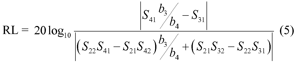
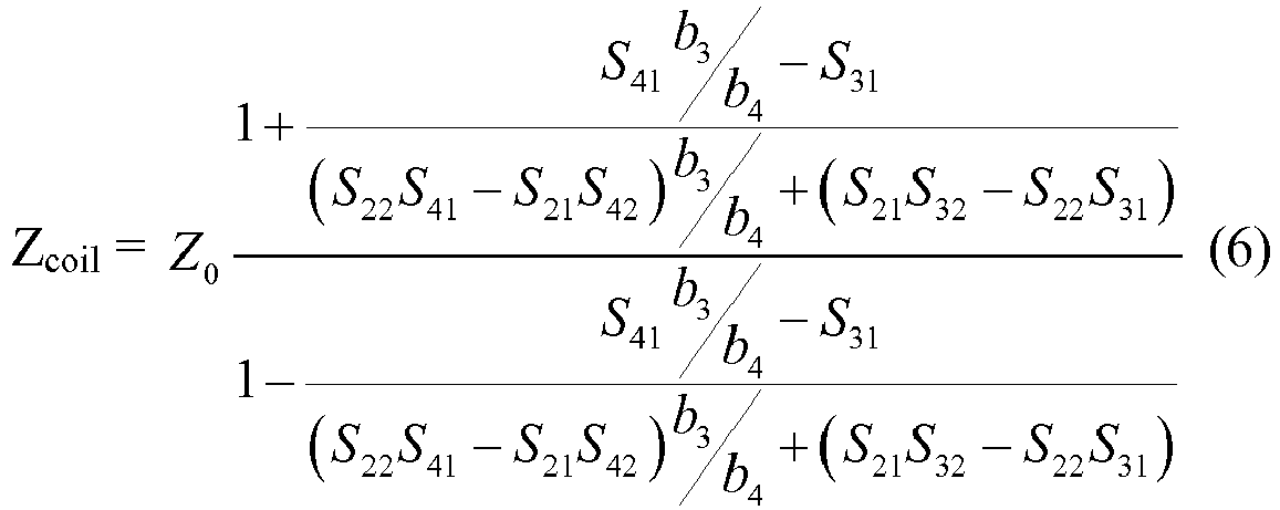
- the vector based measurement in addition to complex forward power PFWD, complex reflected power PREV, complex reflection coefficient r, voltage standing wave ratio VSWR and return loss RL, the vector based measurement also enables the measurement of the complex input impedance of the load coil Zcoil and the load coil current Icoil that the conventional scalar measurement is not able to measure.
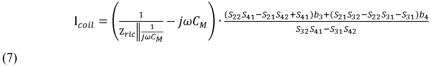
- these operational parameters are calculated by the parameter calculator 205 according to vector based computation as detailed in equations 1) to 7), respectively, which have been tested and verified through lots of experiments.
- Sij represents a complex ratio between an outward traveling voltage wave at the ith port and an incident traveling voltage wave at the jth port
- Z0 represents a characteristic impedance of the RF power amplifier 210
- Zrlc represents a loop impedance without a shunt matching capacitor in a transmit array of the RF antenna 230
- CM stands for the shunt matching capacitor.
- the pre-detected scattering parameters of the four port directional coupler 201 can be limited to a complex transmitting coefficient S21 representative of the complex ratio between the outward traveling voltage wave b2 at the second (output) port and the incident traveling voltage wave a1 at the first (input) port, a complex reflection coefficient S22 representative of the complex ratio between the outward traveling voltage wave b2 at the second (output) port and the incident traveling voltage wave a2 at the second (output) port, a complex coupling coefficient S31 representative of the complex ratio between the outward traveling voltage wave b3 at the third (reverse) port and the incident traveling voltage wave a1 at the first (input) port, a complex coupling coefficient S32 representative of the complex ratio between the outward travelling voltage wave b3 at the third port and the incident travelling voltage wave a2 at the second port, a complex coupling coefficient S21 representative of the complex ratio between the outward traveling voltage wave b2 at the second (output) port and the incident traveling voltage wave a1 at the first (
- the parameter calculator 205 may take the form of an entirely hardware embodiment (including FPGA, ASCII, MPU, etc), an entirely software embodiment (including firmware, resident software, micro-code, etc.) or an embodiment combing software and hardware aspects that may all generally be referred to herein as a "circuit,” “module” or “system.”
- aspects of the present invention may take the form of a computer program product embodied in one or more computer readable medium(s) having computer readable program code embodied thereon.
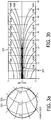
- Fig. 3 illustrates an exemplary experiment result of vector based measurement of the complex reflection coefficient and the related return loss. More specifically, the left Fig. 3(a) illustrates a comparison between the vector based measurement and vector network analyzer (VNA) measurement of the same reflection on the complex plane, e.g., the Smith Chart.
- VNA vector network analyzer
- the VNA measurement measures the reflection of a mismatched load plus a long cable, and is regarded as the baseline to verify the vector based measurement.
- the vector based measurement result designated by the dashed curve 301
- the solid curve 303 closely except for some adjustable phase rotation.
- the comparison result shown in Fig. 3(a) indicates that the vector based method provides an accurate measurement over various phases.
- Fig. 3(b) illustrates a comparison between the vector based measurement and scalar measurement, by projecting the vector based measurement result to the scalar representation 305.
- the horizontal axis of the scalar representation 305 stands for the to-be-measured strength of reflection in terms of return loss.
- the vertical axis of the scalar representation 305 represents the deviation of measured value in the unit of dB.
- the center horizontal line of the scalar representation 305 has 0dB deviation for all reflection, i.e. no measurement error. Every pair of curves above and beneath the center horizontal line outline the upper and lower bounds of measurement outputs at a certain applied directivity value of the directional coupler.
- the measurement output could be any value ranging from 6.5dB to 12.6dB, also in terms of return loss, depending upon the specific phase value of such a 10dB reflection. Therefore, the uncertainty in this measurement is [10dB-3.5dB, 10dB+2.6dB]. Such an uncertainty may bring false fault and operation risk to the RF power amplifier of MRI application. As suggested by the scalar representation 305, the return loss uncertainty can be reduced if the directional coupler is replaced by a better one with a higher directivity.
- the directivity of a directional coupler cannot be increased too much due to limitations in manufacturing and applications.
- the trace 307 pointed by the arrow represents the vector based measurement on almost all phase reflection of 7.3dB return loss, based on the directional coupler of 15 dB directivity.
- the vector based measurement with a coupling device of 15dB in directivity, in this example falls into the uncertainty range of [7.3dB-0.9dB, 7.3dB-0.2dB], which can only be achieved by a coupling device of greater than 25 dB directivity via the conventional scalar method.
- Fig. 4 illustrates a flowchart 400 for determining an operational parameter of an RF power amplifier in a transmit/receive RF system for a magnetic resonance examination system according to one embodiment of the present invention.
- a first coupled signal VREV comprising a first desirable coupled-out fraction of a reflected power flowing from a RF power amplifier toward an RF antenna and a first undesirable coupled-out fraction of a forward power flowing from the RF antenna toward the RF power amplifier is generated via a coupling device.
- the first coupled signal VREV is a first complex value containing amplitude and phase information.
- a second coupled signal VFWD comprising a second desirable coupled-out fraction of the forward power and a second undesirable coupled-out fraction of the reflected power via the coupling device.
- the second coupled signal VFWD is a second complex value containing amplitude and phase information.
- the operational parameter of the RF power amplifier is calculated as a complex-valued function of complex scattering parameters of the coupling device, the first coupled signal VREV and the second coupled signal VFWD.
- each block in the flowchart or block diagrams may represent a module, segment, or portion of code, which comprises one or more executable instructions for implementing the specified logical function(s).
- the functions noted in the block may occur out of the order noted in the figures. For example, two blocks shown in succession may, in fact, be executed substantially concurrently, or the blocks may sometimes be executed in the reverse order, depending upon the functionality involved.
Landscapes
- Physics & Mathematics (AREA)
- General Physics & Mathematics (AREA)
- Condensed Matter Physics & Semiconductors (AREA)
- Magnetic Resonance Imaging Apparatus (AREA)
Description
- The invention relates to a transmit/receive radio frequency system, and more particularly for use in a magnetic resonance examination system, as well as such a magnetic resonance examination system, a method and a computer program to be run on a magnetic resonance examination system.
- Magnetic resonance imaging (MRI) is often used for the examination and treatment of patients. By such a system, the nuclear spins of the body region to be examined are aligned by a static main magnetic field B0 and are excited by transverse magnetic fields B1 oscillating in the radio frequency band. In imaging, relaxation signals are exposed to gradient magnetic fields to localize the resultant resonance. The relaxation signals are received and reconstructed into a single or multi-dimensional image.
- A magnetic resonance imaging system has a number of interacting components, each of which requires the use of modern and elaborate technologies. A central component of a magnetic resonance tomography system is the radio frequency device. This is responsible for the generation of the radio frequency pulses that are radiated into the body region to be imaged. The radio frequency pulses at the output of a radio frequency power amplifier of a magnetic resonance imaging system are conducted via a measurement tool to a transmission coil that radiates the radio frequency pulses into the body region. As used herein "transmission coil", means any antenna device with which the radio frequency pulses can be radiated.
- The RF energy from a magnetic resonance imaging system may cause heating of the tissue of a body. One measure of RF absorption is the specific absorption rate (SAR), which specifies the deposited power per unit mass due to the RF pulse. The SAR value depends on the geometry of the part of the body that is exposed to the RF energy and the location and geometry of the RF source. Maximum values for SAR are specified by safety regulations.
US2015/0002147 provides online monitoring of local SAR in parallel transmission systems. From the high frequency (HF) phase and the HF amplitude of the forward HF wave and the reflected HF wave measured by directional couplers, the local SAR in the patient may be determined with the aid of a voxel model of the patient and electromagnetic simulation. The online monitoring of local SAR aims to prevent a specific patient from excessive RF radiation, e.g., by shutting off the MRI scanner if the measured local SAR exceeds a predetermined threshold. - Superior to SAR monitoring, accurate measurements of the RF power delivered during clinical MRI are essential for safety and regulatory compliance, avoiding inappropriate restrictions on clinical MRI sequences, and for testing the MRI safety of peripheral and interventional devices at known RF exposure levels. Setting precise RF specific absorption rate (SAR) exposure levels for investigators testing devices or MRI methods, or for evaluating SAR in individual burn cases, requires accurate and independent measurement tools. This starts with accurate measurements of the total power deposition. The RF power monitors built into the MRI scanner are usually attached to the RF power amplifier output. However, measuring the power delivered to the body region is complicated by losses in the RF transmission chain, including the cables, switches, the quadrature-hybrid (Q-hybrid) and the transmission coil.
- Currently, power meters in combination with directional couplers are used to measure forward power flowing from the RF power amplifier toward the MRI coil and reflected power reflected back to the RF power amplifier. The power measurement assumes that a forward coupled port PFWD of the directional coupler ideally outputs only a coupled signal that is proportional to the forward power and not affected at all by the reflected power. Likely, a reverse coupled port PREV of the directional coupler ideally outputs only a coupled signal that is proportional to the reflected power and not affected at all by the forward power. Thus, by measuring amplitudes of the coupled signals at the forward and reverse coupled ports PFWD and PREV, the forward power and reflected power travelling on the transmission chain can be determined, respectively, which is also referred to as a scalar method.
- The scalar method based on such assumption implies uncertainty in power measurement, which depends upon a key parameter of the directional coupler, i.e. the directivity. Generally, by using a directional coupler with relatively high directivity, the measurement uncertainty is well controlled and the measurement outcome is still acceptable. However, directional couplers often have to compromise between directivity and power handling capability. The directional couplers with higher directivity but lower power handling capability are subject to more air breakdown risks. In addition, the directivities measured after on-field directional coupler installation generally have some degradation from the ones designed from computer installation. Therefore, a power measurement solution less dependent on the directivity of the directional coupler is desired. Furthermore, in the context of MRI applications with near magnet RF power amplifiers, larger reflection on the transmission chain makes the measurement uncertainty more severe. Additional art is found in
US2015/168516 ,US2010/244840 , and inUS8442616 . - From the foregoing, it is readily appreciated that there is a need for a more accurate power measurement with less dependency on the directivity of the directional coupler. It is consequently an object of the invention to provide the measurement method, a transmit/receive RF system implementing the measurement method, a magnetic resonance examination system, and a computer program product in the independent claims. Embodiments are given in the dependent claims.
- As will be apprciated by one skilled in the art, aspects of the present invention may be embodied as an apparatus, method or computer program product. Accordingly, aspects of the present invention may take the form of an entirely hardware embodiment, an entirely software embodiment (including firmware, resident software, micro-code, etc.) or an embodiment combining software and hardware aspects that may all generally be referred to herein as a "circuit," "module" or "system." Furthermore, aspects of the present invention may take the form of a computer program product embodied in one or more computer readable medium(s) having computer executable code embodied thereon.
- Any combination of one or more computer readable medium(s) may be utilized. The computer readable medium may be a computer readable signal medium or a computer readable storage medium. A 'computer-readable storage medium' as used herein encompasses any tangible storage medium which may store instructions which are executable by a processor of a computing device. The computer-readable storage medium may be referred to as a computer-readable non-transitory storage medium. The computer-readable storage medium may also be referred to as a tangible computer readable medium. In some embodiments, a computer-readable storage medium may also be able to store data which is able to be accessed by the processor of the computing device. Examples of computer-readable storage media include, but are not limited to: a floppy disk, a magnetic hard disk drive, a solid state hard disk, flash memory, a USB thumb drive, Random Access Memory (RAM), Read Only Memory (ROM), an optical disk, a magneto-optical disk, and the register file of the processor. Examples of optical disks include Compact Disks (CD) and Digital Versatile Disks (DVD), for example CD-ROM, CD-RW, CD-R, DVD-ROM, DVD-RW, or DVD-R disks. The term computer readable-storage medium also refers to various types of recording media capable of being accessed by the computer device via a network or communication link. For example a data may be retrieved over a modem, over the internet, or over a local area network. Computer executable code embodied on a computer readable medium may be transmitted using any appropriate medium, including but not limited to wireless, wire line, optical fiber cable, RF, etc., or any suitable combination of the foregoing.
- A computer readable signal medium may include a propagated data signal with computer executable code embodied therein, for example, in baseband or as part of a carrier wave. Such a propagated signal may take any of a variety of forms, including, but not limited to, electro-magnetic, optical, or any suitable combination thereof. A computer readable signal medium may be any computer readable medium that is not a computer readable storage medium and that can communicate, propagate, or transport a program for use by or in connection with an instruction execution system, apparatus, or device.
- 'Computer memory' or 'memory' is an example of a computer-readable storage medium. Computer memory is any memory which is directly accessible to a processor. 'Computer storage' or 'storage' is a further example of a computer-readable storage medium. Computer storage is any non-volatile computer-readable storage medium. In some embodiments computer storage may also be computer memory or vice versa. The contents of the memory and storage may duplicate each other or items depicted as being in one may be stored or copied in the other.
- A 'processor' as used herein encompasses an electronic component which is able to execute a program or machine executable instruction or computer executable code. References to the computing device comprising "a processor" should be interpreted as possibly containing more than one processor or processing core. The processor may for instance be a multi-core processor. A processor may also refer to a collection of processors within a single computer system or distributed amongst multiple computer systems. The term computing device should also be interpreted to possibly refer to a collection or network of computing devices each comprising a processor or processors. The computer executable code may be executed by multiple processors that may be within the same computing device or which may even be distributed across multiple computing devices.
- Computer executable code may comprise machine executable instructions or a program which causes a processor to perform an aspect of the present invention. Computer executable code for carrying out operations for aspects of the present invention may be written in any combination of one or more programming languages, including an object oriented programming language such as Java, Smalltalk, C++ or the like and conventional procedural programming languages, such as the "C" programming language or similar programming languages and compiled into machine executable instructions. In some instances the computer executable code may be in the form of a high level language or in a pre-compiled form and be used in conjunction with an interpreter which generates the machine executable instructions on the fly.
- The computer executable code may execute entirely on the user's computer, partly on the user's computer, as a stand-alone software package, partly on the user's computer and partly on a remote computer or entirely on the remote computer or server. In the latter scenario, the remote computer may be connected to the user's computer through any type of network, including a local area network (LAN) or a wide area network (WAN), or the connection may be made to an external computer (for example, through the Internet using an Internet Service Provider).
- Aspects of the present invention are described with reference to flowchart illustrations and/or block diagrams of methods, apparatus (systems) and computer program products according to embodiments of the invention. It will be understood that each block or a portion of the blocks of the flowchart, illustrations, and/or block diagrams, can be implemented by computer program instructions in form of computer executable code when applicable. It is further understood that, when not mutually exclusive, combinations of blocks in different flowcharts, illustrations, and/or block diagrams may be combined. These computer program instructions may be provided to a processor of a general purpose computer, special purpose computer, or other programmable data processing apparatus to produce a machine, such that the instructions, which execute via the processor of the computer or other programmable data processing apparatus, create means for implementing the functions/acts specified in the flowchart and/or block diagram block or blocks.
- These computer program instructions may also be stored in a computer readable medium that can direct a computer, other programmable data processing apparatus, or other devices to function in a particular manner, such that the instructions stored in the computer readable medium produce an article of manufacture including instructions which implement the function/act specified in the flowchart and/or block diagram block or blocks.
- The computer program instructions may also be loaded onto a computer, other programmable data processing apparatus, or other devices to cause a series of operational steps to be performed on the computer, other programmable apparatus or other devices to produce a computer implemented process such that the instructions which execute on the computer or other programmable apparatus provide processes for implementing the functions/acts specified in the flowchart and/or block diagram block or blocks.In accordance with the invention, a transmit/receive RF system for a magnetic resonance examination system is disclosed. The transmit/receive RF system comprises an RF antenna, an RF power amplifier configured to supply electrical RF power to the RF antenna, a coupling device coupled between the RF power amplifier and the RF antenna and configured to couple out a fraction of a reflected power flowing from the RF antenna toward the RF power amplifier and a fraction of a forward power flowing from the RF power amplifier toward the RF antenna to output a first coupled signal VREV and a second coupled signal VFWD, a wave detector coupled to the coupling device and configured to detect amplitude and phase information of the first coupled signal VREV and the second coupled signal VFWD, and a parameter calculator coupled to the wave detector and configured to calculate an operational parameter of the RF power amplifier based on complex scattering parameters of the coupling device and the detected amplitude and phase information of the first coupled signal VREV and second coupled signal VFWD.
- By taking into account both the amplitude and phase information of the first coupled signal VREV and second coupled signal VFWD, the operational parameter of the RF power amplifier can be calculated in a more accurate and real time fashion based on the complex scattering parameters of the coupling device, the first coupled signal VREV and second coupled signal VFWD. Moreover, the measurement accuracy is less dependent on the directivity of the coupling device, and consequently the coupling device with more power handling capability, less demand on directivity, less requirement on manufacturing consistence and lower cost can be used in the transmit/receive RF system. More specifically, the parameter calculator is configured to calculate the operational parameter as a complex-valued function of the complex scattering parameters, the first coupled signal VREV, and the second coupled signal VFWD. Advantageously, a complex-valued function of the complex scattering parameters, the complex first coupled signal VREV, and the complex second coupled signal VFWD obtains the operational parameter in a complex plane, e.g., the Smith Chart, enabling the real-time measurement of the input impedance of the RF antenna and the coil current of RF antenna. Furthermore, the operational parameter in a complex value assists in phase control of the RF power amplifier, especially in case of large reflection. In another embodiment of the present invention, the operation parameter of the RF power amplifier is any one of the group including the complex forward power, the complex reflected power, a complex reflection coefficient, a voltage standing wave ratio, a complex load impedance (resistance and reactance), a complex coil current and a return loss. The complex load impedance is important to the RF power amplifier, since it will assist in predicting the behavior of the power amplifier and making it stable and robust. The complex coil current is important in parallel transmitting system of MRI and is also a building block of RF current source.
- In yet another embodiment of the present invention, the coupling device comprises a first port, a second port, a third port and a fourth port. The first port is coupled to the RF power amplifier and the second port is coupled to the RF antenna. The third port is configured to output the first coupled signal VREV comprising a first coupled-out fraction of the reflected power and a second coupled-out fraction of the forward power, and the fourth port is configured to output the second coupled signal VFWD comprising a third coupled-out fraction of the forward power and a fourth coupled-out fraction of the reflected power. Since both the first coupled signal VREV and the second coupled signal VFWD comprise a mixture of the forward power and reflected power, the root cause of measurement uncertainty in conventional power monitoring methods, i.e. assuming the first coupled signal VREV and the second coupled signal VFWD as pure signals proportional to the reflected power and the forward power respectively, is eliminated. Advantagesouly, the vector method according to the present invention discriminates different signal components in the mixed VREV and VFWD outputs from the coupling device by using both the magnitude and phase information of the complex first coupled signal VREV, and the complex second coupled signal VFWD and complex scattering parameters of the coupling device, resulting in a more accurate vector based measurement accordingly.
- In yet another embodiment of the present invention, the complex scattering parameters of the coupling device are pre-detected complex values detected when the coupling device is in a standalone state. The coupling device in the standalone state provides the input/output ports readily accessible by a vector network analyzer, which is used for detection of the complex scattering parameters.
- In yet another embodiment of the present invention, the complex scattering parameters are limited to a complex transmitting coefficient S21 representative of a complex ratio between an outward traveling voltage wave at the second port and an incident traveling voltage wave at the first port, a complex reflection coefficient S22 representative of a complex ratio between the outward traveling voltage wave at the second port and an incident traveling voltage wave at the second port, a complex coupling coefficient S31 representative of a complex ratio between an outward traveling voltage wave at the third port and the incident traveling voltage wave at the first port, a complex coupling coefficient S32 representative of a complex ratio between the outward travelling voltage wave at the third port and the incident travelling voltage wave at the second port, a complex coupling coefficient S41 representative of a complex ratio between an outward travelling voltage wave at the fourth port and the incident travelling voltage wave at the first port, and a complex coupling coefficient S42 representative of the complex ratio between the outward travelling voltage wave at the fourth port and the incident traveling voltage wave at the second port. Advantageously, the minimum number of complex scattering parameters is pre-detected for the vector based measurement of operational parameters.
- In yet another embodiment of the present invention, the transmit/receive RF system, further comprises a storage unit coupled to the parameter calculator and configured to store the complex scattering parameters.
- In accordance with the invention, a method for determining an operational parameter of an RF power amplifier in a transmit/receive RF system for a magnetic resonance examination system is disclosed. The method comprises the steps of receiving a first coupled signal VREV comprising a first coupled-out fraction of a reflected power flowing from the RF power amplifier toward an RF antenna and a second coupled-out fraction of the forward power flowing from the RF antenna toward the RF power amplifier via a coupling device coupled between the RF power amplifier and the RF antenna, receiving a second coupled signal VFWD comprising a third coupled-out fraction of the forward power and a fourth coupled-out fraction of the reflected power via the coupling device, and calculating the operational parameter of the RF power amplifier as a complex-valued function of complex scattering parameters of the coupling device, the first coupled signal VREV and the second coupled signal VFWD. Both the first coupled signal VREV and the second coupled signal VFWD are complex values containing amplitude and phase information.
- In an embodiment of the present invention, the method further comprises detecting the phase and amplitude information of the first coupled signal VREV and the second coupled signal VFWD.
- In another embodiment of the present invention, the method further comprises predetecting the complex scattering parameters of the coupling device when the coupling device is in a standalone state.
- In another embodiment of the present invention, the method further comprises storing the complex scattering parameters of the coupling device in a storage unit in the transmit/receive radio RF system.
- The method of the invention can be advantageously carried out on magnetic resonance examination devices in clinical use. To this end, it is merely necessary to utilize a computer program by which the magnetic resonance examination device is controlled such that it performs the above-explained method steps of the invention. The computer program may be present either on a data carrier or be present in a data network so as to be downloaded for installation in the control unit of the magnetic resonance examination device.
- The enclosed drawings disclose preferred embodiments of the invention. It should be understood, however, that the drawings are designed for the purpose of illustration only and not as a definition of the limits of the invention. In the drawings:
-
Fig. 1 shows a magnetic resonance imaging (MRI) system according to one embodiment of the present invention; -
Fig. 2 shows a transmit/receive RF system according to one embodiment of the present invention; -
Fig. 3 shows an exemplary experiment result of vector based measurement of the complex reflection coefficient and the related return loss.Fig. 3 includesFig. 3(a) illustrating a comparison between the vector based measurement and vector network analyzer (VNA) measurement of the same reflection on the complex plane, andFig. 3(b) illustrating a comparison between the vector based measurement and scalar measurement; -
Fig. 4 shows a flow chart of a method for determining an operational parameter of an RF power amplifier in a transmit/receive RF system for a magnetic resonance examination system according to one embodiment of the present invention. - With reference to
Fig. 1 , a magneticresonance imaging system 100 includes ahousing 4. A subject 6 (e.g., a human, an object, etc.) is at least partially disposed within abore 8 of thehousing 4 for one or more MRI procedures (e.g., spin echo, gradient echo, stimulated echo, etc.). Amagnet 10 resides in thehousing 4. Themagnet 10 typically is a persistent superconducting magnet surrounded by acryo shrouding 12. However, other known magnets (e.g., a resistive magnet, a permanent magnet, etc.) can be employed. Themagnet 10 produces a stationary and substantially homogeneous main magnetic field B0 in thesubject 6. As a result, the nuclei within the subject 6 preferentially align in a parallel and/or an anti-parallel direction with respect to the magnetic flux lines of the magnetic field B0. Typical magnetic field strengths are about 0.5 Tesla (0.5T), 1.0T, 1.5T, 3T or higher (e.g., about 7T). - Magnetic field gradient coils 14 are arranged in and/or on the
housing 4. Thecoils 14 superimpose various magnetic field gradients G on the magnetic field B0 in order to define an imaging slice or volume and to otherwise spatially encode excited nuclei. Image data signals are produced by switching gradient fields in a controlled sequence by agradient controller 16. One or more radio frequency (RF) coils or resonators are used for excitation pulses within an imaging region. Suitable RF coils include afull body coil 18 located in thebore 8 of thesystem 100, a local coil (e.g., ahead coil 20 surrounding a head of the subject 6), and/or one or more surface coils. - An
excitation source 22 generates the excitation pulses and provides these pulses to the RF coils 18 and/or 20 through aRF amplifier 24 and aswitch 26. Theexcitation source 22 includes at least one transmitter (TX) 28. Ameasurement device 44 is coupled to the output of theRF amplifier 24 to measure the forward power and reflected power travelling on the transmission chain. Advantageously, themeasurement device 44 can provide a more accurate forward and reflected power measurement result, which is further sent to ascanner controller 30 for excitation pulse adjustment. Thescanner controller 30 controls theexcitation source 22 based on operator instructions. For instance, if an operator selects a protocol for acquisition of proton spectra, thescanner controller 30 accordingly instructs theexcitation source 22 to generate excitation pulses at a corresponding frequency, and thetransmitter 28 generates and transmits the pulses to the RF coils 18 or 20 via theamplifier 24. The excitation pulses are fed to theRF amplifier 24. Conventional MRI systems typically utilize multiple amplifiers, in case more than one excitation spectra is used. - The excitation pulses are sent from the
amplifier 24 to thecoils switch 26. Thescanner controller 30 also controls theswitch 26. During an excitation phase, thescanner controller 30 controls theswitch 26 and allows the excitation pulses to pass through theswitch 26 to the RF coils 18 or 20, but not to a receivesystem 32. Upon receiving excitation pulses, the RF coils 18 or 20 resonate and apply the pulses into the imaging region. Thegradient controller 16 suitably operates the gradient coils 14 to spatially encode the resulting MR signals. - During the readout phase, the
switch 26 connects the receivesystem 32 to one or more receive coils to acquire the spatially encoded MR signals. The receivesystem 32 includes one ormore receivers 34 depending on the receive coil configuration. The acquired MR signals are conveyed (serially and/or in parallel) through adata pipeline 36 and processed by aprocessing component 38 to produce one or more images. - The reconstructed images are stored in a
storage component 40 and/or displayed on aninterface 42, other display device, printed, communicated over a network (e.g., the Internet, a local area network (LAN) ...), stored within a storage medium, and/or otherwise used. Theinterface 42 also allows an operator to control the magneticresonance imaging scanner 100 through conveying instructions to thescanner controller 30. -
Fig. 2 illustrates a block diagram of a transmit/receiveRF system 200 according to one embodiment of the present invention. The transmit/receiveRF system 200 includes aRF power amplifier 210, ameasurement device 220 and aRF antenna 230. In one embodiment, the measurement device220 further includes acoupling device 201, awave detector 203 and aparameter calculator 205. Optionally, themeasurement device 220 can also include amemory unit 207. In the embodiment ofFig. 2 , thecoupling device 201 is in the form of a four port directional coupler including atransmision line 221 connecting a first (input)port 211 and a second (output)port 213 and acoupling line 223 connecting a third (reverse coupled)port PREV 215 and a fourth (forward coupled)port PFWD 217. Theinput port 211 of thedirectional coupler 201 is connected to the output of theRF power amplifier 210 and theouptput port 213 is connected to theRF antenna 230, e.g., the surface coil or local coils. - A directivity (D) of the
direcitonal coupler 201 is a measure of how well thedirectional cupler 201 distinguishs the opposite travelling (forward and reflected) signals on thetransmission line 221. Ideally, the reverse coupledport PREV 215 outputs only a coupled signal proportional to the reflected power (scaled version of the reflected power) and the forward coupledport PFWD 217 outputs only a coupled signal proportional to the forward power (scaled version of the forward power). While, in practice, the reverse and forward coupled port PREV andPFWD directional coupler 201 actually output a mixture of the reflected power and forward power. More specifically, the reverse coupledport PREV 215 outputs a first coupled signal VREV comprising a first scaled fraction of forward power flowing from theinput port 211 to theoutput port 213 and a second scaled fraction of reflected power flowing from theoutput port 213 to theinput port 211, and the forward coupledport PFWD 217 outputs a second coupled signal VFWD comprising a third scaled fraction of forward power flowing from theinput port 211 to theoutput port 213 and a fourth scaled fraction of reflected power flowing from theoutput port 213 to theinput port 211. - As power travelling between any two ports of the
directional coupler 201 may be described using complex scattering parameters (S-parameters) defined in terms of incident and outward travelling voltage waves (a and b) at theinput port 211, theoutput port 213, the reverse coupledport PREV 215 and the forward coupledport PFWD 217 of thedirectional coupler 201, an insight of the present invention is that the operational parameters of theRF power amplifier 201 can be measured by themeasurement device 220 in a more accurate way via a vector computation based on complex scattering parameters and complex coupled signals VREV and VFWD containing both amplitude and phase information. The insight of the present invention is based on the discovery of the inventor that assuming the first coupled signal VREV and the second coupled signal VFWD as pure signals proportional to the reflected power and the forward power respectivelyis the root cause of measurement uncertainty in conventional power monitoring methods. By taking into account both the amplitude and phase informtion, different signal components in the mixed VREV and VFWD outputs from thecoupling device 201 can be discriminated, , and hence the measurement uncertainty can be reduced significantly. Moreover, as the result of the vector based measurement can be displayed on the complex plane, e.g., the Smith Chart, the functionality of themeasurement devcie 220 in accordance with the present invention can be extened beyond the capability of conventinal power monitoring methods to complex domain of measurment. For example, the vector based measurement enables the measurement of the input impedance of the body coil Zcoil and the coil current Icoil. The input impedance of the body coil Zcoil is important to theRF power amplifier 210, since it will assist in predicting the behavior of the power amplifier and making it stable and robust. The coil current estimation Icoil is important in parallel transmitting system of MRI and is also a building block of RF current source. Furthermore, the vector based measurement excels in phase control of the RF power amplifier, especially in case of large reflection. In addition to above mentioned benefits, the vector based measurement is less dependent on the directivity D of the directional coupler, which brings more flexibility in the design of power handling capability. - In one embodiment, a vector network analyzer (not shown) can measure scattering parameters of the
directional coupler 201 in a standalone state, e.g., in advance of its implementation in the transmit/receiveRF system 200. In the example ofFIG.2 , the scattering parameters of thedirectional coupler 201 are pre-detected values detected when thedirectional coupler 201 is in the standalone state, and stored in thememory unit 207 for measuring the operational parameters of theRF power amplifier 210 in real time. Alternatively, the pre-detected scattering parameters can be provided to an input interface of theparameter calculator 205 directly. Advantageously, thedirectional coupler 201 in the standalone state facilitates its connection to the vector network analyzer since its input/output ports are readily accessible. For on-board directional couplers, e.g., implemented in the transmit/receive RF systems already, the first (input)port 211 has been connected to the output of theRF amplifier 210 electrically and therefore becomes not readily accessible by the vector network analyzer. In this instance, thefirst port 211 can be disconnected from the output of theRF amplifier 210 temporarily until the pre-detection of the scattering parameters by the vector network analyzer completes. Furthermore, the directional coupling devices are generally made of endurable materials, e.g., fiber glass in FR4 or Rogers substrate in the form of simple circuit layouts, resulting in a passive device with complex scattering parameters insensitive to large signal variations within the specified operational range. Consequently, the scattering parameters pre-detected during the standalone state of the coupling device are applicable in the real-time vector based measurement. - As above-mentioned, the vector based measurement calls for the first and second coupled signals VREV and VFWD containing both the amplitude and phase information. To the end, the first and second coupled signals VREV and VFWD are directed to the
wave detector 203. Thewave detector 203 converts the magnitude and phase information of the first and second coupled signals VREV and VFWD to DC voltages. Alternatively, thewave detector 203 converts the magnitude and phase information of the first and second coupled signals VREV and VFWD to sampled values in a digital fashion based on the principle of software-defined radio (SWR). Theparameter calculator 205 calculates the operational parameters of theRF power amplifier 210 based on the DC voltages or sampled digital values representative of magnitude and phase information of the first and second coupled signals VREV and VFWD and the complex scattering parameters. - Advantageously, in addition to complex forward power PFWD, complex reflected power PREV, complex reflection coefficient r, voltage standing wave ratio VSWR and return loss RL, the vector based measurement also enables the measurement of the complex input impedance of the load coil Zcoil and the load coil current Icoil that the conventional scalar measurement is not able to measure. In one embodiment, these operational parameters are calculated by the
parameter calculator 205 according to vector based computation as detailed in equations 1) to 7), respectively, which have been tested and verified through lots of experiments.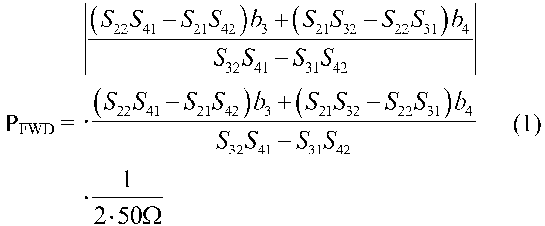


- According to equations 1) to 7), it can be concluded that it is not necessary to detect all the 16 scattering parameters of the four port
directional coupler 201 in advance. Advantageously, the pre-detected scattering parameters of the four portdirectional coupler 201 can be limited to a complex transmitting coefficient S21 representative of the complex ratio between the outward traveling voltage wave b2 at the second (output) port and the incident traveling voltage wave a1 at the first (input) port, a complex reflection coefficient S22 representative of the complex ratio between the outward traveling voltage wave b2 at the second (output) port and the incident traveling voltage wave a2 at the second (output) port, a complex coupling coefficient S31 representative of the complex ratio between the outward traveling voltage wave b3 at the third (reverse) port and the incident traveling voltage wave a1 at the first (input) port, a complex coupling coefficient S32 representative of the complex ratio between the outward travelling voltage wave b3 at the third port and the incident travelling voltage wave a2 at the second port, a complex coupling coefficient S41 representative of the complex ratio between the outward travelling voltage wave b4 at the fourth port and the incident travelling voltage wave a1 at the first port, and a complex coupling coefficient S42 representative of the complex ratio between the outward travelling voltage wave b4 at the fourth port and the incident traveling voltage wave a2 at the second port. - As will be appreciated by one skilled in the art, the
parameter calculator 205 may take the form of an entirely hardware embodiment (including FPGA, ASCII, MPU, etc), an entirely software embodiment (including firmware, resident software, micro-code, etc.) or an embodiment combing software and hardware aspects that may all generally be referred to herein as a "circuit," "module" or "system." Furthermore, aspects of the present invention may take the form of a computer program product embodied in one or more computer readable medium(s) having computer readable program code embodied thereon. -
Fig. 3 illustrates an exemplary experiment result of vector based measurement of the complex reflection coefficient and the related return loss. More specifically, the leftFig. 3(a) illustrates a comparison between the vector based measurement and vector network analyzer (VNA) measurement of the same reflection on the complex plane, e.g., the Smith Chart. The VNA measurement measures the reflection of a mismatched load plus a long cable, and is regarded as the baseline to verify the vector based measurement. As illustrated inFig. 3(a) , the vector based measurement result, designated by the dashedcurve 301, follows the VNA measurement, designated by thesolid curve 303, closely except for some adjustable phase rotation. The comparison result shown inFig. 3(a) indicates that the vector based method provides an accurate measurement over various phases. -
Fig. 3(b) illustrates a comparison between the vector based measurement and scalar measurement, by projecting the vector based measurement result to thescalar representation 305. The horizontal axis of thescalar representation 305 stands for the to-be-measured strength of reflection in terms of return loss. The vertical axis of thescalar representation 305 represents the deviation of measured value in the unit of dB. The center horizontal line of thescalar representation 305 has 0dB deviation for all reflection, i.e. no measurement error. Every pair of curves above and beneath the center horizontal line outline the upper and lower bounds of measurement outputs at a certain applied directivity value of the directional coupler. For example, if a reflection of 10dB, in terms of return loss, is measured by the scalar method with a directivity of 20dB in its directional coupler, the measurement output could be any value ranging from 6.5dB to 12.6dB, also in terms of return loss, depending upon the specific phase value of such a 10dB reflection. Therefore, the uncertainty in this measurement is [10dB-3.5dB, 10dB+2.6dB]. Such an uncertainty may bring false fault and operation risk to the RF power amplifier of MRI application. As suggested by thescalar representation 305, the return loss uncertainty can be reduced if the directional coupler is replaced by a better one with a higher directivity. However, the directivity of a directional coupler cannot be increased too much due to limitations in manufacturing and applications. Advantageously, the vector based method can achieve a much more accurate measurement on the reflection of 7.3dB return loss, i.e. VSWR∼=2.52, with almost all phase angles, resulting in a range of [7.3dB-0.9dB, 7.3dB-0.2dB], based on a directional coupler with only 15dB of directivity. Also shown inFig. 3(b) , thetrace 307 pointed by the arrow represents the vector based measurement on almost all phase reflection of 7.3dB return loss, based on the directional coupler of 15 dB directivity. The vector based measurement with a coupling device of 15dB in directivity, in this example (all-phase 7.3dB reflection), falls into the uncertainty range of [7.3dB-0.9dB, 7.3dB-0.2dB], which can only be achieved by a coupling device of greater than 25 dB directivity via the conventional scalar method. -
Fig. 4 illustrates a flowchart 400 for determining an operational parameter of an RF power amplifier in a transmit/receive RF system for a magnetic resonance examination system according to one embodiment of the present invention. Atstep 401, a first coupled signal VREV comprising a first desirable coupled-out fraction of a reflected power flowing from a RF power amplifier toward an RF antenna and a first undesirable coupled-out fraction of a forward power flowing from the RF antenna toward the RF power amplifier is generated via a coupling device. The first coupled signal VREV is a first complex value containing amplitude and phase information. Atstep 403, a second coupled signal VFWD comprising a second desirable coupled-out fraction of the forward power and a second undesirable coupled-out fraction of the reflected power via the coupling device. The second coupled signal VFWD is a second complex value containing amplitude and phase information. Atstep 405, the operational parameter of the RF power amplifier is calculated as a complex-valued function of complex scattering parameters of the coupling device, the first coupled signal VREV and the second coupled signal VFWD. - The flowchart and block diagrams in the figures illustrate the architecture, functionality, and operation of possible implementations of systems, methods and computer program products according to various embodiments of the present invention. In this regard, each block in the flowchart or block diagrams may represent a module, segment, or portion of code, which comprises one or more executable instructions for implementing the specified logical function(s). It should also be noted that, in some alternative implementations, the functions noted in the block may occur out of the order noted in the figures. For example, two blocks shown in succession may, in fact, be executed substantially concurrently, or the blocks may sometimes be executed in the reverse order, depending upon the functionality involved. It will also be noted that each block of the block diagrams and/or flowchart illustration, and combinations of blocks in the block diagrams and/or flowchart illustration, can be implemented by special purpose hardware-based systems that perform the specified functions or acts, or combinations of special purpose hardware and computer instructions.
- The embodiments described above are illustrative examples and it should not be construed that the present invention is limited to these particular embodiments. Thus, various changes and modifications may be effected by one skilled in the art without departing from the scope of the invention as defined in the appended claims.
Claims (14)
- A transmit/receive radio frequency (RF) system (200) for a magnetic resonance examination system comprising:- an RF antenna (230);- an RF power amplifier (210) configured to supply electrical RF power to the RF antenna (230); and- a coupling device (201) coupled between the RF power amplifier (210) and the RF antenna (210) and configured to couple out fractions of a reflected power flowing from the RF antenna (230) toward the RF power amplifier (210) and a forward power flowing from the RF power amplifier (210) toward the RF antenna (210) to output a first coupled signal VREV and a second coupled signal VFWD;- a wave detector (203) coupled to the coupling device (201) and configured to detect amplitude and phase information of the first coupled signal VREV and the second coupled signal VFWD; and- a parameter calculator (205) coupled to the wave detector (203) and configured to calculate an operational parameter of the RF power amplifier (210) based on complex scattering parameters of the coupling device (201) and the detected amplitude and phase information of the first coupled signal VREV and second coupled signal VFWD.
- The transmit/receive RF system (200) of claim 1, wherein the operation parameter of the RF power amplifier (210) is any one of the group including the forward power, the reflected power, a complex reflection factor, a voltage standing wave ratio, a complex load impedance, a complex coil current and a return loss.
- The transmit/receive RF system (200) of claim 1, wherein the coupling device (201) comprises a first port (211), a second port (213), a third port (215) and a fourth port (217), the first port (211) coupled to the RF power amplifier (210) and the second port (213) coupled to the RF antenna (230), the third port (215) configured to output the first coupled signal VREV comprising a first coupled-out fraction of the reflected power and a second coupled-out fraction of the forward power, and the fourth port (217) configured to output the second coupled signal VFWD comprising a third coupled-out fraction of the forward power and a fourth coupled-out fraction of the reflected power.
- The transmit/receive RF system (200) of claim 1, wherein the complex scattering parameters of the coupling device (201) are pre-detected values detected when the coupling device (201) is in a standalone state.
- The transmit/receive RF system (200) of claim 1, wherein the complex scattering parameters are limited to a complex transmitting coefficient S21 representative of a complex ratio between an outward traveling voltage wave at the second port (213) and an incident traveling voltage wave at the first port (211), a complex reflection coefficient S22 representative of a complex ratio between the outward traveling voltage wave at the second port (213) and an incident traveling voltage wave at the second port (213), a complex coupling coefficient S31 representative of a complex ratio between an outward traveling voltage wave at the third port (215) and the incident traveling voltage wave at the first port (211), a complex coupling coefficient S32 representative of a complex ratio between the outward travelling voltage wave at the third port (215) and the incident travelling voltage wave at the second port (213), a complex coupling coefficient S41 representative of a complex ratio between an outward travelling voltage wave at the fourth port (217) and the incident travelling voltage wave at the first port (211), and a complex coupling coefficient S42 representative of the complex ratio between the outward travelling voltage wave at the fourth port (217) and the incident traveling voltage wave at the second port (213).
- The transmit/receive RF system (200) of claim 1, further comprising: a storage unit (207) coupled to the parameter calculator (205) and configured to store the complex scattering parameters.
- A method for determining an operational parameter of an RF power amplifier (210) in a transmit/receive radio frequency (RF) system (200) for a magnetic resonance examination system, the method comprising:- receiving a first coupled signal VREV comprising a first coupled-out fraction of a reflected power flowing from the RF power amplifier (210) toward an RF antenna (230) and a second coupled-out fraction of the forward power flowing from the RF antenna (230) toward the RF power amplifier (210) via a coupling device (201) coupled between the RF power amplifier (210) and the RF antenna (230), wherein the first coupled signal VREV is a first complex value containing amplitude and phase information;- receiving a second coupled signal VFWD comprising a third coupled-out fraction of the forward power and a fourth coupled-out fraction of the reflected power via the coupling device (201), wherein the second coupled signal VFWD is a second complex value containing amplitude and phase information; and- calculating the operational parameter of the RF power amplifier (210) as a complex-valued function of complex scattering parameters of the coupling device (201), the first coupled signal VREV and the second coupled signal VFWD.
- The method claim 7, further comprising: detecting the phase and amplitude information of the first coupled signal VREV and the second coupled signal VFWD.
- The method of claim 7, further comprising: predetecting the complex scattering parameters of the coupling device (201) when the coupling device (201) is in a standalone state.
- The method of claim 7, wherein the complex scattering parameters are limited to a complex transmitting coefficient S21 representative of a complex ratio between an outward traveling voltage wave at the second port (213) and an incident traveling voltage wave at the first port (211), a complex reflection coefficient S22 representative of a complex ratio between the outward traveling voltage wave at the second port (213) and an incident traveling voltage wave at the second port (213), a complex coupling coefficient S31 representative of a complex ratio between an outward traveling voltage wave at the third port (215) and the incident traveling voltage wave at the first port (211), a complex coupling coefficient S32 representative of a complex ratio between the outward travelling voltage wave at the third port (215) and the incident travelling voltage wave at the second port (213), a complex coupling coefficient S41 representative of a complex ratio between an outward travelling voltage wave at the fourth port (217) and the incident travelling voltage wave at the first port (211), and a complex coupling coefficient S42 representative of the complex ratio between the outward travelling voltage wave at the fourth port (217) and the incident traveling voltage wave at the second port (213).
- The method of claim 7, further comprising: storing the complex scattering parameter of the coupling device (201) in a storage unit (207) in the transmit/receive radio RF system (200).
- The method of claim 7, wherein the operation parameter of the RF power amplifier (210) is any one of the group including the forward power, the reflected power, a complex reflection factor, a voltage standing wave ratio, a complex load impedance, a complex coil current and a return loss.
- A magnetic resonance examination system (100) comprising the transmit/receive RF system (200) as set forth in any one of claims 1-6.
- A computer program product stored on a computer-readable medium comprising software code adapted to perform the steps of the method according to any one of claims 7-12 when executed on a data-processing apparatus.
Applications Claiming Priority (3)
| Application Number | Priority Date | Filing Date | Title |
|---|---|---|---|
| CN2016097295 | 2016-08-30 | ||
| EP16196001 | 2016-10-27 | ||
| PCT/EP2017/070889 WO2018041643A1 (en) | 2016-08-30 | 2017-08-17 | A transmit/receive radio frequency (rf) system for a magnetic resonance examination system and method thereof |
Publications (2)
| Publication Number | Publication Date |
|---|---|
| EP3507616A1 EP3507616A1 (en) | 2019-07-10 |
| EP3507616B1 true EP3507616B1 (en) | 2020-01-22 |
Family
ID=59856485
Family Applications (1)
| Application Number | Title | Priority Date | Filing Date |
|---|---|---|---|
| EP17765088.4A Active EP3507616B1 (en) | 2016-08-30 | 2017-08-17 | A transmit/receive radio frequency (rf) system for a magnetic resonance examination system and method thereof |
Country Status (5)
| Country | Link |
|---|---|
| US (1) | US10942231B2 (en) |
| EP (1) | EP3507616B1 (en) |
| JP (1) | JP6636672B2 (en) |
| CN (1) | CN109690339B (en) |
| WO (1) | WO2018041643A1 (en) |
Families Citing this family (9)
| Publication number | Priority date | Publication date | Assignee | Title |
|---|---|---|---|---|
| US11082015B2 (en) | 2018-11-05 | 2021-08-03 | Andrew Wireless Systems Gmbh | Methods and apparatuses for reflection measurements |
| DE102019128204B4 (en) * | 2019-10-18 | 2021-05-06 | Topinox Sarl | Method for calibrating a microwave module, calibration system, microwave module and cooking device |
| DE102019128203B3 (en) * | 2019-10-18 | 2021-04-22 | Tq-Systems Gmbh | Method for calibrating a microwave module, calibration system, microwave module and microwave device |
| CN114200365B (en) * | 2020-09-02 | 2024-03-19 | 西门子(深圳)磁共振有限公司 | magnetic resonance imaging device |
| WO2023006085A1 (en) * | 2021-07-30 | 2023-02-02 | Shanghai United Imaging Healthcare Co., Ltd. | Systems and methods for magnetic resonance imaging |
| CN114415097B (en) * | 2021-12-31 | 2023-06-30 | 江苏美时医疗技术有限公司 | Magnetic resonance phased array coil performance rapid detection device and detection method thereof |
| US11888504B2 (en) * | 2022-02-18 | 2024-01-30 | Apple Inc. | Electronic devices with output load independent detection capabilities |
| CN117424657B (en) * | 2023-12-18 | 2024-02-23 | 四川恒湾科技有限公司 | Method for detecting channel connectivity of independent receiver of base station radio frequency system |
| CN121091050B (en) * | 2025-11-11 | 2026-02-17 | 深圳飞骧科技股份有限公司 | Test system, method and storage medium for coupler directionality |
Family Cites Families (17)
| Publication number | Priority date | Publication date | Assignee | Title |
|---|---|---|---|---|
| US4962359A (en) * | 1989-06-29 | 1990-10-09 | Hewlett-Packard Company | Dual directional bridge and balun used as reflectometer test set |
| JP4665836B2 (en) * | 2006-05-31 | 2011-04-06 | 日本ビクター株式会社 | Music classification device, music classification method, and music classification program |
| US7966140B1 (en) | 2008-04-18 | 2011-06-21 | Gholson Iii Norman H | Radio frequency power meter |
| US8248075B2 (en) | 2008-09-30 | 2012-08-21 | Vivant Medical, Inc. | System, apparatus and method for dissipating standing wave in a microwave delivery system |
| DE102008063630B4 (en) * | 2008-12-18 | 2011-04-14 | Siemens Aktiengesellschaft | Method for controlling a radio frequency transmitter, radio frequency transmitter, radio frequency controller and magnetic resonance imaging system |
| US8102177B2 (en) * | 2009-03-31 | 2012-01-24 | General Electric Company | Using S-parameter measurements to manage SAR and transmit gain in MRI |
| WO2014057391A1 (en) * | 2012-10-12 | 2014-04-17 | Koninklijke Philips N.V. | Rf amplifier control in parallel rf transmission based on power requirements |
| US9312592B2 (en) | 2013-03-15 | 2016-04-12 | Keysight Technologies, Inc. | Adjustable directional coupler circuit |
| US9625541B2 (en) | 2013-07-01 | 2017-04-18 | Siemens Aktiengesellschaft | Safety tests for systems monitoring local SAR |
| JP2016526459A (en) * | 2013-07-11 | 2016-09-05 | コーニンクレッカ フィリップス エヌ ヴェKoninklijke Philips N.V. | Corrected magnetic resonance imaging using coil sensitivity |
| US20150081238A1 (en) * | 2013-08-27 | 2015-03-19 | Purdue Research Foundation | RF Signal Meter |
| US9541592B1 (en) * | 2013-09-03 | 2017-01-10 | Christos Tsironis | Noise parameter measurement system |
| DE102013226170B4 (en) * | 2013-12-17 | 2018-04-05 | Siemens Healthcare Gmbh | Method and device for spatial homogenization of the field strength of high-frequency pulses of a transmitting antenna of a magnetic resonance tomography device |
| US10197646B2 (en) * | 2014-05-06 | 2019-02-05 | Siemens Aktiengesellschaft | Decoupling of parallel transmission arrays in magnetic resonance imaging |
| CN107533116B (en) * | 2015-04-24 | 2021-07-06 | 皇家飞利浦有限公司 | Multi-channel transmit/receive radio frequency (RF) systems |
| WO2017020196A1 (en) * | 2015-07-31 | 2017-02-09 | 深圳市大疆创新科技有限公司 | Detection device, detection system, detection method and portable apparatus |
| JP6147450B1 (en) * | 2017-01-04 | 2017-06-14 | 株式会社日立製作所 | Magnetic resonance imaging apparatus and method of operating the same |
-
2017
- 2017-08-17 EP EP17765088.4A patent/EP3507616B1/en active Active
- 2017-08-17 WO PCT/EP2017/070889 patent/WO2018041643A1/en not_active Ceased
- 2017-08-17 JP JP2019511730A patent/JP6636672B2/en active Active
- 2017-08-17 CN CN201780052400.9A patent/CN109690339B/en active Active
- 2017-08-17 US US16/327,882 patent/US10942231B2/en active Active
Non-Patent Citations (1)
| Title |
|---|
| None * |
Also Published As
| Publication number | Publication date |
|---|---|
| US20190195970A1 (en) | 2019-06-27 |
| JP2019530494A (en) | 2019-10-24 |
| CN109690339B (en) | 2022-05-24 |
| CN109690339A (en) | 2019-04-26 |
| US10942231B2 (en) | 2021-03-09 |
| JP6636672B2 (en) | 2020-01-29 |
| EP3507616A1 (en) | 2019-07-10 |
| WO2018041643A1 (en) | 2018-03-08 |
Similar Documents
| Publication | Publication Date | Title |
|---|---|---|
| EP3507616B1 (en) | A transmit/receive radio frequency (rf) system for a magnetic resonance examination system and method thereof | |
| US8102177B2 (en) | Using S-parameter measurements to manage SAR and transmit gain in MRI | |
| Snyder et al. | Initial results of cardiac imaging at 7 Tesla | |
| Alecci et al. | Radio frequency magnetic field mapping of a 3 Tesla birdcage coil: experimental and theoretical dependence on sample properties | |
| US7633293B2 (en) | Radio frequency field localization for magnetic resonance | |
| CN103027679B (en) | For controlling the method for magnetic resonance system | |
| Graesslin et al. | Comprehensive RF safety concept for parallel transmission MR | |
| Oh et al. | Experimental and numerical assessment of MRI‐induced temperature change and SAR distributions in phantoms and in vivo | |
| CN104736050B (en) | The Forecasting Methodology of MR imaging apparatus and SAR | |
| CN107533116B (en) | Multi-channel transmit/receive radio frequency (RF) systems | |
| CN104375105B (en) | Automatic high frequency shimming for coil configures | |
| JP6147450B1 (en) | Magnetic resonance imaging apparatus and method of operating the same | |
| KR101932104B1 (en) | Apparatus and method for detecting antenna coils | |
| CN108303661A (en) | Magnetic resonance emits the correction of signal | |
| Giovannetti et al. | Classical and lateral skin effect contributions estimation in strip MR coils | |
| Solbach et al. | Near-magnet power amplifier with built-in coil current sensing | |
| Redpath et al. | Estimating achievable signal-to-noise ratios of MRI transmit-receive coils from radiofrequency power measurements: applications in quality control | |
| CN115327458B (en) | Magnetic resonance system, transmitting device, transmitting method, pre-scanning method | |
| CN219245744U (en) | A device for measuring the uniformity of the magnetic field of a magnetic resonance emitter coil | |
| Pedersen et al. | General purpose electronics for real‐time processing and encoding of non‐MR data in MR acquisitions | |
| US20240201290A1 (en) | Local coils with integrated excitation field sensors | |
| US11774528B2 (en) | Magnetic resonance tomography scanner and method for testing | |
| US11099249B2 (en) | Feeding a coil for magnetic resonance imaging | |
| Chen et al. | A Radio Frequency Magnetic Field Generator for Magnetic Resonance Compatibility Testing of Active Implantable Medical Devices | |
| JPS6368147A (en) | Magnetic resonance apparatus |
Legal Events
| Date | Code | Title | Description |
|---|---|---|---|
| STAA | Information on the status of an ep patent application or granted ep patent |
Free format text: STATUS: UNKNOWN |
|
| STAA | Information on the status of an ep patent application or granted ep patent |
Free format text: STATUS: THE INTERNATIONAL PUBLICATION HAS BEEN MADE |
|
| PUAI | Public reference made under article 153(3) epc to a published international application that has entered the european phase |
Free format text: ORIGINAL CODE: 0009012 |
|
| STAA | Information on the status of an ep patent application or granted ep patent |
Free format text: STATUS: REQUEST FOR EXAMINATION WAS MADE |
|
| REG | Reference to a national code |
Ref country code: DE Ref legal event code: R079 Ref document number: 602017011008 Country of ref document: DE Free format text: PREVIOUS MAIN CLASS: G01R0033260000 Ipc: G01R0033280000 |
|
| 17P | Request for examination filed |
Effective date: 20190401 |
|
| AK | Designated contracting states |
Kind code of ref document: A1 Designated state(s): AL AT BE BG CH CY CZ DE DK EE ES FI FR GB GR HR HU IE IS IT LI LT LU LV MC MK MT NL NO PL PT RO RS SE SI SK SM TR |
|
| AX | Request for extension of the european patent |
Extension state: BA ME |
|
| GRAP | Despatch of communication of intention to grant a patent |
Free format text: ORIGINAL CODE: EPIDOSNIGR1 |
|
| STAA | Information on the status of an ep patent application or granted ep patent |
Free format text: STATUS: GRANT OF PATENT IS INTENDED |
|
| RIC1 | Information provided on ipc code assigned before grant |
Ipc: G01R 33/28 20060101AFI20190626BHEP Ipc: G01R 33/26 20060101ALI20190626BHEP Ipc: G01R 33/36 20060101ALI20190626BHEP |
|
| INTG | Intention to grant announced |
Effective date: 20190725 |
|
| GRAS | Grant fee paid |
Free format text: ORIGINAL CODE: EPIDOSNIGR3 |
|
| DAV | Request for validation of the european patent (deleted) | ||
| DAX | Request for extension of the european patent (deleted) | ||
| GRAA | (expected) grant |
Free format text: ORIGINAL CODE: 0009210 |
|
| STAA | Information on the status of an ep patent application or granted ep patent |
Free format text: STATUS: THE PATENT HAS BEEN GRANTED |
|
| AK | Designated contracting states |
Kind code of ref document: B1 Designated state(s): AL AT BE BG CH CY CZ DE DK EE ES FI FR GB GR HR HU IE IS IT LI LT LU LV MC MK MT NL NO PL PT RO RS SE SI SK SM TR |
|
| REG | Reference to a national code |
Ref country code: GB Ref legal event code: FG4D |
|
| REG | Reference to a national code |
Ref country code: CH Ref legal event code: EP |
|
| REG | Reference to a national code |
Ref country code: AT Ref legal event code: REF Ref document number: 1227251 Country of ref document: AT Kind code of ref document: T Effective date: 20200215 |
|
| REG | Reference to a national code |
Ref country code: IE Ref legal event code: FG4D |
|
| REG | Reference to a national code |
Ref country code: DE Ref legal event code: R096 Ref document number: 602017011008 Country of ref document: DE |
|
| RAP2 | Party data changed (patent owner data changed or rights of a patent transferred) |
Owner name: KONINKLIJKE PHILIPS N.V. |
|
| REG | Reference to a national code |
Ref country code: GB Ref legal event code: 746 Effective date: 20200323 |
|
| REG | Reference to a national code |
Ref country code: DE Ref legal event code: R084 Ref document number: 602017011008 Country of ref document: DE |
|
| REG | Reference to a national code |
Ref country code: NL Ref legal event code: MP Effective date: 20200122 |
|
| REG | Reference to a national code |
Ref country code: LT Ref legal event code: MG4D |
|
| PG25 | Lapsed in a contracting state [announced via postgrant information from national office to epo] |
Ref country code: NL Free format text: LAPSE BECAUSE OF FAILURE TO SUBMIT A TRANSLATION OF THE DESCRIPTION OR TO PAY THE FEE WITHIN THE PRESCRIBED TIME-LIMIT Effective date: 20200122 Ref country code: PT Free format text: LAPSE BECAUSE OF FAILURE TO SUBMIT A TRANSLATION OF THE DESCRIPTION OR TO PAY THE FEE WITHIN THE PRESCRIBED TIME-LIMIT Effective date: 20200614 Ref country code: FI Free format text: LAPSE BECAUSE OF FAILURE TO SUBMIT A TRANSLATION OF THE DESCRIPTION OR TO PAY THE FEE WITHIN THE PRESCRIBED TIME-LIMIT Effective date: 20200122 Ref country code: RS Free format text: LAPSE BECAUSE OF FAILURE TO SUBMIT A TRANSLATION OF THE DESCRIPTION OR TO PAY THE FEE WITHIN THE PRESCRIBED TIME-LIMIT Effective date: 20200122 Ref country code: NO Free format text: LAPSE BECAUSE OF FAILURE TO SUBMIT A TRANSLATION OF THE DESCRIPTION OR TO PAY THE FEE WITHIN THE PRESCRIBED TIME-LIMIT Effective date: 20200422 |
|
| PG25 | Lapsed in a contracting state [announced via postgrant information from national office to epo] |
Ref country code: HR Free format text: LAPSE BECAUSE OF FAILURE TO SUBMIT A TRANSLATION OF THE DESCRIPTION OR TO PAY THE FEE WITHIN THE PRESCRIBED TIME-LIMIT Effective date: 20200122 Ref country code: BG Free format text: LAPSE BECAUSE OF FAILURE TO SUBMIT A TRANSLATION OF THE DESCRIPTION OR TO PAY THE FEE WITHIN THE PRESCRIBED TIME-LIMIT Effective date: 20200422 Ref country code: GR Free format text: LAPSE BECAUSE OF FAILURE TO SUBMIT A TRANSLATION OF THE DESCRIPTION OR TO PAY THE FEE WITHIN THE PRESCRIBED TIME-LIMIT Effective date: 20200423 Ref country code: LV Free format text: LAPSE BECAUSE OF FAILURE TO SUBMIT A TRANSLATION OF THE DESCRIPTION OR TO PAY THE FEE WITHIN THE PRESCRIBED TIME-LIMIT Effective date: 20200122 Ref country code: SE Free format text: LAPSE BECAUSE OF FAILURE TO SUBMIT A TRANSLATION OF THE DESCRIPTION OR TO PAY THE FEE WITHIN THE PRESCRIBED TIME-LIMIT Effective date: 20200122 Ref country code: IS Free format text: LAPSE BECAUSE OF FAILURE TO SUBMIT A TRANSLATION OF THE DESCRIPTION OR TO PAY THE FEE WITHIN THE PRESCRIBED TIME-LIMIT Effective date: 20200522 |
|
| REG | Reference to a national code |
Ref country code: DE Ref legal event code: R097 Ref document number: 602017011008 Country of ref document: DE |
|
| PG25 | Lapsed in a contracting state [announced via postgrant information from national office to epo] |
Ref country code: DK Free format text: LAPSE BECAUSE OF FAILURE TO SUBMIT A TRANSLATION OF THE DESCRIPTION OR TO PAY THE FEE WITHIN THE PRESCRIBED TIME-LIMIT Effective date: 20200122 Ref country code: LT Free format text: LAPSE BECAUSE OF FAILURE TO SUBMIT A TRANSLATION OF THE DESCRIPTION OR TO PAY THE FEE WITHIN THE PRESCRIBED TIME-LIMIT Effective date: 20200122 Ref country code: SM Free format text: LAPSE BECAUSE OF FAILURE TO SUBMIT A TRANSLATION OF THE DESCRIPTION OR TO PAY THE FEE WITHIN THE PRESCRIBED TIME-LIMIT Effective date: 20200122 Ref country code: EE Free format text: LAPSE BECAUSE OF FAILURE TO SUBMIT A TRANSLATION OF THE DESCRIPTION OR TO PAY THE FEE WITHIN THE PRESCRIBED TIME-LIMIT Effective date: 20200122 Ref country code: CZ Free format text: LAPSE BECAUSE OF FAILURE TO SUBMIT A TRANSLATION OF THE DESCRIPTION OR TO PAY THE FEE WITHIN THE PRESCRIBED TIME-LIMIT Effective date: 20200122 Ref country code: SK Free format text: LAPSE BECAUSE OF FAILURE TO SUBMIT A TRANSLATION OF THE DESCRIPTION OR TO PAY THE FEE WITHIN THE PRESCRIBED TIME-LIMIT Effective date: 20200122 Ref country code: RO Free format text: LAPSE BECAUSE OF FAILURE TO SUBMIT A TRANSLATION OF THE DESCRIPTION OR TO PAY THE FEE WITHIN THE PRESCRIBED TIME-LIMIT Effective date: 20200122 Ref country code: ES Free format text: LAPSE BECAUSE OF FAILURE TO SUBMIT A TRANSLATION OF THE DESCRIPTION OR TO PAY THE FEE WITHIN THE PRESCRIBED TIME-LIMIT Effective date: 20200122 |
|
| REG | Reference to a national code |
Ref country code: AT Ref legal event code: MK05 Ref document number: 1227251 Country of ref document: AT Kind code of ref document: T Effective date: 20200122 |
|
| PLBE | No opposition filed within time limit |
Free format text: ORIGINAL CODE: 0009261 |
|
| STAA | Information on the status of an ep patent application or granted ep patent |
Free format text: STATUS: NO OPPOSITION FILED WITHIN TIME LIMIT |
|
| 26N | No opposition filed |
Effective date: 20201023 |
|
| PG25 | Lapsed in a contracting state [announced via postgrant information from national office to epo] |
Ref country code: IT Free format text: LAPSE BECAUSE OF FAILURE TO SUBMIT A TRANSLATION OF THE DESCRIPTION OR TO PAY THE FEE WITHIN THE PRESCRIBED TIME-LIMIT Effective date: 20200122 Ref country code: AT Free format text: LAPSE BECAUSE OF FAILURE TO SUBMIT A TRANSLATION OF THE DESCRIPTION OR TO PAY THE FEE WITHIN THE PRESCRIBED TIME-LIMIT Effective date: 20200122 |
|
| PG25 | Lapsed in a contracting state [announced via postgrant information from national office to epo] |
Ref country code: PL Free format text: LAPSE BECAUSE OF FAILURE TO SUBMIT A TRANSLATION OF THE DESCRIPTION OR TO PAY THE FEE WITHIN THE PRESCRIBED TIME-LIMIT Effective date: 20200122 |
|
| PG25 | Lapsed in a contracting state [announced via postgrant information from national office to epo] |
Ref country code: MC Free format text: LAPSE BECAUSE OF FAILURE TO SUBMIT A TRANSLATION OF THE DESCRIPTION OR TO PAY THE FEE WITHIN THE PRESCRIBED TIME-LIMIT Effective date: 20200122 |
|
| REG | Reference to a national code |
Ref country code: CH Ref legal event code: PL |
|
| PG25 | Lapsed in a contracting state [announced via postgrant information from national office to epo] |
Ref country code: CH Free format text: LAPSE BECAUSE OF NON-PAYMENT OF DUE FEES Effective date: 20200831 Ref country code: LI Free format text: LAPSE BECAUSE OF NON-PAYMENT OF DUE FEES Effective date: 20200831 Ref country code: LU Free format text: LAPSE BECAUSE OF NON-PAYMENT OF DUE FEES Effective date: 20200817 |
|
| REG | Reference to a national code |
Ref country code: BE Ref legal event code: MM Effective date: 20200831 |
|
| PG25 | Lapsed in a contracting state [announced via postgrant information from national office to epo] |
Ref country code: BE Free format text: LAPSE BECAUSE OF NON-PAYMENT OF DUE FEES Effective date: 20200831 Ref country code: IE Free format text: LAPSE BECAUSE OF NON-PAYMENT OF DUE FEES Effective date: 20200817 |
|
| PG25 | Lapsed in a contracting state [announced via postgrant information from national office to epo] |
Ref country code: TR Free format text: LAPSE BECAUSE OF FAILURE TO SUBMIT A TRANSLATION OF THE DESCRIPTION OR TO PAY THE FEE WITHIN THE PRESCRIBED TIME-LIMIT Effective date: 20200122 Ref country code: MT Free format text: LAPSE BECAUSE OF FAILURE TO SUBMIT A TRANSLATION OF THE DESCRIPTION OR TO PAY THE FEE WITHIN THE PRESCRIBED TIME-LIMIT Effective date: 20200122 Ref country code: CY Free format text: LAPSE BECAUSE OF FAILURE TO SUBMIT A TRANSLATION OF THE DESCRIPTION OR TO PAY THE FEE WITHIN THE PRESCRIBED TIME-LIMIT Effective date: 20200122 |
|
| PG25 | Lapsed in a contracting state [announced via postgrant information from national office to epo] |
Ref country code: MK Free format text: LAPSE BECAUSE OF FAILURE TO SUBMIT A TRANSLATION OF THE DESCRIPTION OR TO PAY THE FEE WITHIN THE PRESCRIBED TIME-LIMIT Effective date: 20200122 Ref country code: AL Free format text: LAPSE BECAUSE OF FAILURE TO SUBMIT A TRANSLATION OF THE DESCRIPTION OR TO PAY THE FEE WITHIN THE PRESCRIBED TIME-LIMIT Effective date: 20200122 |
|
| PG25 | Lapsed in a contracting state [announced via postgrant information from national office to epo] |
Ref country code: SI Free format text: LAPSE BECAUSE OF FAILURE TO SUBMIT A TRANSLATION OF THE DESCRIPTION OR TO PAY THE FEE WITHIN THE PRESCRIBED TIME-LIMIT Effective date: 20200122 |
|
| PGFP | Annual fee paid to national office [announced via postgrant information from national office to epo] |
Ref country code: DE Payment date: 20250827 Year of fee payment: 9 |
|
| PGFP | Annual fee paid to national office [announced via postgrant information from national office to epo] |
Ref country code: GB Payment date: 20250826 Year of fee payment: 9 |
|
| PGFP | Annual fee paid to national office [announced via postgrant information from national office to epo] |
Ref country code: FR Payment date: 20250825 Year of fee payment: 9 |