EP3415213B1 - Filter element - Google Patents
Filter element Download PDFInfo
- Publication number
- EP3415213B1 EP3415213B1 EP18185865.5A EP18185865A EP3415213B1 EP 3415213 B1 EP3415213 B1 EP 3415213B1 EP 18185865 A EP18185865 A EP 18185865A EP 3415213 B1 EP3415213 B1 EP 3415213B1
- Authority
- EP
- European Patent Office
- Prior art keywords
- filter medium
- layers
- embossing
- filter
- layer
- Prior art date
- Legal status (The legal status is an assumption and is not a legal conclusion. Google has not performed a legal analysis and makes no representation as to the accuracy of the status listed.)
- Active
Links
Images


Classifications
-
- B—PERFORMING OPERATIONS; TRANSPORTING
- B01—PHYSICAL OR CHEMICAL PROCESSES OR APPARATUS IN GENERAL
- B01D—SEPARATION
- B01D29/00—Filters with filtering elements stationary during filtration, e.g. pressure or suction filters, not covered by groups B01D24/00 - B01D27/00; Filtering elements therefor
- B01D29/01—Filters with filtering elements stationary during filtration, e.g. pressure or suction filters, not covered by groups B01D24/00 - B01D27/00; Filtering elements therefor with flat filtering elements
- B01D29/016—Filters with filtering elements stationary during filtration, e.g. pressure or suction filters, not covered by groups B01D24/00 - B01D27/00; Filtering elements therefor with flat filtering elements with corrugated, folded or wound filtering elements
-
- B—PERFORMING OPERATIONS; TRANSPORTING
- B01—PHYSICAL OR CHEMICAL PROCESSES OR APPARATUS IN GENERAL
- B01D—SEPARATION
- B01D46/00—Filters or filtering processes specially modified for separating dispersed particles from gases or vapours
- B01D46/52—Particle separators, e.g. dust precipitators, using filters embodying folded corrugated or wound sheet material
- B01D46/521—Particle separators, e.g. dust precipitators, using filters embodying folded corrugated or wound sheet material using folded, pleated material
- B01D46/523—Particle separators, e.g. dust precipitators, using filters embodying folded corrugated or wound sheet material using folded, pleated material with means for maintaining spacing between the pleats or folds
-
- B—PERFORMING OPERATIONS; TRANSPORTING
- B01—PHYSICAL OR CHEMICAL PROCESSES OR APPARATUS IN GENERAL
- B01D—SEPARATION
- B01D29/00—Filters with filtering elements stationary during filtration, e.g. pressure or suction filters, not covered by groups B01D24/00 - B01D27/00; Filtering elements therefor
- B01D29/11—Filters with filtering elements stationary during filtration, e.g. pressure or suction filters, not covered by groups B01D24/00 - B01D27/00; Filtering elements therefor with bag, cage, hose, tube, sleeve or like filtering elements
- B01D29/111—Making filtering elements
-
- B—PERFORMING OPERATIONS; TRANSPORTING
- B01—PHYSICAL OR CHEMICAL PROCESSES OR APPARATUS IN GENERAL
- B01D—SEPARATION
- B01D29/00—Filters with filtering elements stationary during filtration, e.g. pressure or suction filters, not covered by groups B01D24/00 - B01D27/00; Filtering elements therefor
- B01D29/11—Filters with filtering elements stationary during filtration, e.g. pressure or suction filters, not covered by groups B01D24/00 - B01D27/00; Filtering elements therefor with bag, cage, hose, tube, sleeve or like filtering elements
- B01D29/13—Supported filter elements
- B01D29/15—Supported filter elements arranged for inward flow filtration
- B01D29/21—Supported filter elements arranged for inward flow filtration with corrugated, folded or wound sheets
-
- B—PERFORMING OPERATIONS; TRANSPORTING
- B01—PHYSICAL OR CHEMICAL PROCESSES OR APPARATUS IN GENERAL
- B01D—SEPARATION
- B01D46/00—Filters or filtering processes specially modified for separating dispersed particles from gases or vapours
- B01D46/52—Particle separators, e.g. dust precipitators, using filters embodying folded corrugated or wound sheet material
- B01D46/521—Particle separators, e.g. dust precipitators, using filters embodying folded corrugated or wound sheet material using folded, pleated material
-
- B—PERFORMING OPERATIONS; TRANSPORTING
- B01—PHYSICAL OR CHEMICAL PROCESSES OR APPARATUS IN GENERAL
- B01D—SEPARATION
- B01D2201/00—Details relating to filtering apparatus
- B01D2201/12—Pleated filters
- B01D2201/127—Pleated filters with means for keeping the spacing between the pleats
Definitions
- the invention relates to a filter element, in particular of an internal combustion engine, in particular of a motor vehicle, with a filter medium composed of a media web that consists of several layers and is folded along fold lines.
- a filter element for removing particles from a fluid flow, in particular particles from a fuel flow of an internal combustion engine is known.
- the filter element comprises an upper end plate, a lower end plate and an annular, star-shaped pleated filter medium arranged between them.
- a multilayer, web-shaped filter medium, which is folded to form the filter element, is used for production.
- the individual layers in particular lie loosely on top of one another.
- the filter medium is fed to a heat-introducing embossing unit, in particular an ultrasonic embossing unit, by means of a feed device, which embosses kink lines in the filter medium.
- the filter medium is then folded along the folding lines by means of a folding device. Layers of the multi-layer filter medium are welded during embossing along the fold lines with the aid of the heat-absorbing embossing unit.
- document DE 197 35 993 A1 discloses a filter element which has a star-shaped, zigzag-folded filter web, the filter web consisting of metal or glass fibers with knockouts.
- the glass fiber fleece can be laminated or coated with polyester fibers on one or both sides, whereby embossing can be carried out.
- the invention is based on the object of designing a filter element of the type mentioned at the beginning with which the layers of the web-shaped filter medium can be easily and precisely connected and folded with one another and the completely folded filter element has an even higher stability and filter efficiency.
- the filter medium is shaped into at least one further functional area in at least one section.
- the layers of the multilayer filter medium can be layers of different or identical materials.
- the layers of the filter medium are materially connected to one another along the embossments of the at least one further functional area.
- material connections in particular welded, melted or glued connections, the connection partners are held together by atomic or molecular forces. The material connections are permanent and robust against environmental influences. With the embossing and the additional material connection, the stability of the filter medium in the folded state is increased.
- the functionality of the filter element is improved by the combination of embossing and material connection. Due to the fact that material connections can only be made in the area of the embossings and the layers of the filter medium can lie loosely against one another in other sections, a total area of the filter medium, which is affected by embossing and connections to fluid flow may be compromised, minimized. In this way, the active area of the filter medium for filtration becomes optimized. Furthermore, the embossing and the material connection can advantageously be carried out in one process step, so that the manufacturing effort can be reduced.
- the most varied of filter layers in particular made of different materials and / or different structures and / or different dimensions, can also be combined with one another.
- two or more layers can be embossed and materially connected to one another.
- the folding lines can be embossed and the layers of the multilayer filter medium can be materially connected to one another along the embossing.
- embossing the fold lines folding can be improved, in particular simplified and made more precise.
- the stability of the filter medium in the folded state can be increased further.
- the folding lines can advantageously be embossed without a material connection.
- a material connection can advantageously also be implemented without embossing the kink lines.
- the at least one further functional area is a spacer knob and / or a stabilizing knob.
- the at least one spacer knob With the at least one spacer knob, the flat sections adjacent when the filter medium is folded can be kept spaced apart from one another. In this way, it can be prevented that the flat sections can lie directly against one another, which would impair the flow through the filter medium.
- at least one spacer knob can be provided in each or each second section.
- a plurality of spacer knobs is provided between two adjacent folding lines.
- spacing knobs corresponding to one another can advantageously be configured in adjacent sections mirrored to a respective plane which contains a kink line and runs perpendicular to the unfolded filter medium web. The mirrored spacer knobs can rest against one another when the filter medium is folded.
- the at least one spacer knob can advantageously have the shape of half a cylinder jacket.
- the at least one spacer knob can advantageously have the shape of half a conical jacket to have. This has the advantage that the spacer knob can compensate for the wedge shape of the folds when the filter medium is folded.
- the spacer knob can thus rest over its length on an opposing fold surface or an approximately opposing other spacer knob.
- the axis of the cylinder jacket or the conical jacket can advantageously run perpendicular to the folding lines.
- the at least one spacer knob can furthermore stabilize the flat section in which it is arranged.
- the layers of the multi-layer filter medium can be laminated, calendered, welded, fused or glued along the at least one embossing. In this way, a simple material connection between the layers can be realized.
- the filter medium is folded in a zigzag shape.
- a filter medium folded in a zigzag shape can easily be shaped into a closed filter element, in particular a round filter element.
- a filter element folded in a zigzag shape can simply be shaped into a flat filter element.
- At least one, preferably two, of the layers of the multi-layer filter medium can advantageously be made of synthetic material.
- Synthetic materials can easily be embossed by means of an energy-generating embossing process and at the same time bonded with one another or with a different, not synthetic material. Synthetic materials can be robust. Long service lives can be achieved with them. They can be easily manufactured and recycled.
- At least one of the layers of the multilayer filter medium has a grid, preferably a plastic grid, on grids increase the stability of the filter medium.
- plastic With the energy-introducing embossing unit, plastic can simply be heated, embossed and cohesively connected, in particular welded, to the remaining layers.
- At least one of the layers of the multilayer filter medium has a meltblown layer. Due to the three-dimensional storage structure With the meltblown layer, a very good filtration performance can be achieved, which can increase the service life of the filter element. Meltblown layers can easily be shaped, embossed and connected in a materially bonded manner, in particular welded.
- the layers can be embossed and materially connected to one another by means of an energy-introducing method, in particular by means of ultrasonic embossing. With an energy-generating process, the embossing and the material connection can simply be realized at the same time.
- a pre-filter layer and a fine filter layer can be joined to one another in the flow direction of the filter medium, a first support layer being applied to the raw side of the pre-filter layer and a second supporting layer to absorb the longitudinal or transverse forces in the event of tensile or compressive loads on the clean side of the fine filter layer can, wherein the two support layers can each have different average maximum tensile forces in the longitudinal or transverse direction.
- the longitudinal direction is defined as the direction in which the filter medium, in particular web-shaped and preferably rectangular, has its greatest length, in particular the direction of advance during the manufacture of the filter medium.
- the transverse direction is defined as the direction which runs along the width of the filter medium, perpendicular to the longitudinal direction and along which the filter medium is preferably folded.
- the different strengths have the advantage that the difference in length of the outer layers around the neutral layer in the middle is compensated for in the longitudinal and transverse directions in the event of deflections during the lamination, roll cutting, embossing and setting-up process, thus improving or improving processability is only ensured in certain media configurations.
- the rigidity required for connecting the bellows and the end plate of the filter element, which is required when welding the filter medium to a thermoplastic end plate or when immersing the filter medium in a viscous adhesive, is advantageously achieved by means of the support layer for absorbing the transverse forces.
- the support layers can advantageously fulfill the function of drainage to prevent the filter medium from being packaged together.
- Another advantage of the support layers is the possibility of the folds "on Block "because the flow is guaranteed due to the adjacent support layers.
- the width-related bending stiffness S determined in accordance with DIN 53121 is used below as a further material parameter.
- the standard provides for various measurement methods, preferably a rectangular sample with the width b is clamped along a width and loaded with a force F at a distance I from the clamp, resulting in a maximum deflection f as a shift of the force application point.
- the width-related bending stiffness S is calculated from this
- the average maximum tensile force of the support layer of the filter medium absorbing the transverse forces can be greater than 10 N in the longitudinal direction.
- the average maximum tensile force of the support layer of the filter medium absorbing the transverse forces can be greater than 20 N in the transverse direction.
- the average maximum tensile force of the support layer of the filter medium that absorbs the longitudinal forces can be greater than 20 N in the longitudinal direction.
- the average maximum tensile force of the support layer of the filter medium absorbing the longitudinal forces can be greater than 10 N in the transverse direction.
- the width-related flexural rigidity of the support layer of the filter medium that absorbs the transverse forces in the longitudinal direction can be greater than 0.1 Nm, in particular greater than 0.15 Nm.
- the width-related flexural rigidity of the support layer of the filter medium that absorbs the transverse forces in the transverse direction can be greater than 0.3 Nm, in particular greater than 0.4 Nm.
- the width-related flexural rigidity of the support layer of the filter medium which absorbs the longitudinal forces can be greater than 0.3 Nm, particularly preferably greater than 0.45 Nm, in the longitudinal direction.
- the width-related flexural rigidity of the support layer of the filter medium which absorbs the longitudinal forces in the transverse direction can be greater than 0.1 Nm, particularly preferably greater than 0.15 Nm.
- the support layers can each be designed in the form of a lattice which can have intersecting threads, wherein the intersecting threads can span a thread angle.
- the thread angle of the support layer of the filter medium responsible for absorbing the transverse forces can be in the range from 70 ° to 120 °, preferably in the range from 80 ° to 100 °, particularly preferably 90 °.
- the thread angle of the support layer of the filter medium responsible for absorbing the longitudinal forces can be in the range from 40 ° to 80 °, in particular in the range from 50 ° to 70 °.
- the pre-filter layer of the filter medium can be formed from a meltblown layer with a thickness in the range from 0.1 mm to 1 mm and a weight per unit area in the range from 10 g / m 2 to 200 g / m 2 .
- the thickness of the meltblown layer of the filter medium can be between 0.2 mm and 0.4 mm and the weight per unit area between 90 g / m 2 and 110 g / m 2 .
- the fiber diameter of the prefilter layer and / or the fine filter layer of the filter medium can be in the range from 0.1 ⁇ m to 10 ⁇ m.
- the prefilter layer and / or the fine filter layer of the filter medium can be made from materials selected from the group consisting of polybutylene terephthalate (PBT) meltblown, polyamide (PA) meltblown, polypropylene (PP) meltblown and polyethersulfone (PES) meltblown .
- PBT polybutylene terephthalate
- PA polyamide
- PP polypropylene
- PES polyethersulfone
- the fine filter layer of the filter medium can be formed from a meltblown layer with a thickness in the range from 0.1 mm to 1.5 mm and a weight per unit area in the range from 10 g / m 2 to 200 g / m 2 .
- the thickness of the meltblown layer of the filter medium can be between 0.6 mm and 1.0 mm and the weight per unit area between 90 g / m 2 and 110 g / m 2 .
- the filter medium can additionally have a third filter layer.
- the third filter layer of the filter medium can be formed from a meltblown layer with a thickness in the range from 0.1 mm to 1 mm and a weight per unit area in the range from 10 g / m 2 to 100 g / m 2 .
- the thickness of the meltblown layer of the filter medium can be between 0.2 mm and 0.4 mm and the weight per unit area between 30 g / m 2 and 60 g / m 2 .
- the third filter layer of the filter medium can be made from materials selected from the group consisting of polybutylene terephthalate (PBT) meltblown, polyamide (PA) meltblown, polypropylene (PP) meltblown and polyethersulfone (PES) meltblown.
- PBT polybutylene terephthalate
- PA polyamide
- PP polypropylene
- PES polyethersulfone
- the fiber diameter of the third filter layer of the filter medium can be in the range from 0.1 ⁇ m to 10 ⁇ m.
- the third filter layer can be designed as an absolute separator.
- the support layers and / or the fine filter layer and / or the pre-filter layer can consist of a combination selected from the group consisting of lattice spunbond, spunbond-spunbond, spunbond filter layers and lattice filter layers.
- the spunbond can be a spunbond.
- the filter layers and / or fine filter layer and / or pre-filter layer can consist of dry-laid fleece, in particular carded fleece, and / or of wet-laid fleece.
- a filter layer and / or fine filter layer and / or prefilter layer can be made from materials selected from a group consisting of synthetic polymers, preferably polybutylene terephthalate (PBT), polyamide (PA), polyethersulfone (PES), polyethylene terephthalate (PET), and / or from natural polymers and / or mixtures thereof.
- synthetic polymers preferably polybutylene terephthalate (PBT), polyamide (PA), polyethersulfone (PES), polyethylene terephthalate (PET), and / or from natural polymers and / or mixtures thereof.
- the anergy-introducing embossing unit is designed for embossing and materially connecting layers of the multilayer filter medium along at least one Functional area in at least one section of the filter medium between adjacent folding lines.
- the energy-introducing embossing unit is designed in such a way that it simultaneously embosses the filter medium and connects the layers there with one another, in particular welded.
- the filter medium is thus permanently laminated along the at least one further functional area, particularly robust against environmental influences. In this way, the stability of the filter medium in the folded state is increased.
- the defined and stable connection of the layers facilitates and improves the subsequent folding.
- the layers are welded to one another in such a way that the bond strength at the connection or weld lines of the layers is at least as great as the material strength within the individual layers.
- the energy-introducing embossing unit can advantageously be designed to emboss the kink lines and / or materially connect the layers of the multilayer filter medium along the kink lines. In this way, folding can be further facilitated and improved.
- An ultrasonic embossing unit can preferably be used as the energy-introducing embossing unit.
- the energy can alternatively also be introduced by means of thermal calenders, lasers or other energy sources.
- layers of the multilayer filter medium are not connected to one another before the embossing.
- a preceding operation for joining, in particular lamination, of the layers can thus be dispensed with.
- the layers lie flat against one another as separate layers until the embossing process and can be moved relative to one another. Tensions between the layers that can occur during embossing and folding are easily balanced. This simplifies the embossing process and the folding process.
- the energy-introducing embossing unit can be followed by an erecting unit for the zigzag-shaped folding of the web-shaped Filter medium.
- the filter medium can be folded with the erection unit directly after the embossing and cohesive connection, in particular welding. In this way, the layers can easily align with each other after each embossing of a kink line in order to relieve tension, which further simplifies the folding process and increases precision.
- the energy-introducing embossing unit can have an anvil roller with embossing webs, an ultrasound-operated sonotrode and an embossing die, which is in particular formed at least by the sonotrode.
- the web-shaped filter medium can easily be embossed and welded in one work step in a continuous process.
- a different type of energy-introducing embossing unit in particular with an ultrasonic stamp moving with the web-shaped filter medium, or a rotating ultrasonic sonotrode roller, can also be used.
- a nipping roller in particular a driven nip roller, can be arranged in front of and behind the anvil roller.
- the positions of the nip rolls relative to the anvil roll can be changed in order to set an inlet angle and an outlet angle over the anvil roll.
- Driven nip rollers can also be used to transport the filter medium webs.
- the speed of the nip rollers can advantageously be adjusted.
- the position and / or speed of the nip rollers can be adapted to the properties of the filter medium web, in particular material composition, layer thicknesses and / or dimensions, in order to enable optimal embossing and material connection, in particular welding.
- Layers of the multi-layer filter medium are embossed along at least one functional area in at least one section of the filter medium between adjacent fold lines with the energy-introducing embossing unit and are materially connected during embossing.
- the crease lines can also be embossed into the web-shaped filter medium with the energy-introducing embossing unit and / or the layers of the multilayer filter medium can be materially connected along the crease lines.
- the filter medium can be embossed and cohesively connected, in particular welded, by means of an anvil roller with embossing webs, an ultrasound-operated sonotrode and an embossing punch, which is at least also formed by the sonotrode.
- the multilayer filter medium can advantageously be folded in a zigzag shape with an erecting unit after the embossing and cohesive connection, in particular welding.
- FIG. 1 a device 10 for zigzag folding a multilayer filter medium web 12 of a filter element 13 is shown.
- the filter element 13 is used to filter liquid or gaseous fluids, for example engine oil, fuel, combustion air or compressed air, in motor vehicles.
- the filter medium web 12 consists, as in Figures 2 and 3 shown, of three layers or plies that are initially loosely attached to each other.
- the two outer layers consist of plastic grids 14.
- a meltblown layer 16, which forms the middle layer, is arranged between the plastic grids 14.
- Alternative embodiments provide two or more layers.
- the endless filter medium web 12 is unrolled from a roller 18 in the conveying direction, indicated by an arrow 20, and passed between two transport rollers 22.
- the filter medium web 12 is fed to an ultrasonic embossing unit 24 without being specifically heated beforehand.
- the ultrasonic embossing unit 24 has an anvil roller 26 which is equipped on the circumference with a multiplicity of embossing webs 28.
- the embossing webs 28 are arranged distributed at uniform intervals along the circumference of the anvil roller 26.
- the embossing webs 28 can also be arranged distributed at irregular intervals along the circumference of the anvil roller 26. They each extend axially to the anvil roll 26, in the radial direction.
- the extent of the embossing webs 28 in the circumferential direction is in each case approximately 0.5 mm to 2 mm.
- the radially outer surfaces of the embossing webs 28 are smooth. Changing fold heights can be achieved through the uneven spacing of the embossing webs 28.
- the ultrasonic embossing unit 24 also has an ultrasonic unit 30 with which ultrasound is introduced into a sonotrode 32 in a manner which is not of further interest here.
- the ultrasonic unit 30 with the sonotrode 32 is located next to the anvil roller 26.
- the sonotrode 32 forms an embossing stamp which cooperates with the embossing webs 28 of the anvil roller 26.
- the filter medium web 12 is moved through between the anvil roller 26 and the sonotrode 32.
- the plastic grids 14 and the meltblown layer 16 can move relative to one another. In this way, mechanical stresses between the layers are relieved.
- the introduction of ultrasound at a tip 34 of the sonotrode 32 leads to the heating of the filter medium web 12 in the areas defined by the embossing webs 28.
- the areas embossed in this way form crease lines 36 for the subsequent folding of the filter medium web 12.
- the crease lines 36 are shown in FIG Figure 3 in detail and with a finished filter element 13 in the Figures 4 and 5 shown.
- a flow direction of the fluid to be cleaned through the filter element 13 is shown in FIG Figure 5 indicated by arrows 41.
- the inflow side, ie the raw side, of the filter element 13 is located in the Figure 5 above.
- the outflow side, i.e. the clean side, of the filter element 13 is in Figure 5 below.
- the heights of the embossing webs 28 in the radial direction, the distance between the tip 34 of the sonotrode 32 and the embossing webs 28 and the energy emitted by the sonotrode 32 onto the filter medium web 12 are dependent on the properties of the filter medium web 12, for example, the type of material, the layer thicknesses and the total thickness are coordinated in order to weld the plastic grids 14 and the meltblown layer 16 to the sonotrode 32 along the bending line 36 at the same time as the embossing process and thus bond them with one another.
- the tip 34 of the sonotrode 32 is guided along the flat sections 37 between adjacent folding lines 36 for embossing spacer knobs 39 on the filter medium web 12.
- the plastic grids 14 and the meltblown layer 16 are welded to the embossing of the spacer knobs 39 and are thus firmly connected.
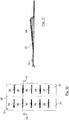
- Figure 5 only four of the spacer knobs 39 are shown by way of example. In reality, as in Figure 8 shown, a plurality of spacer knobs 39 are arranged in each section 37.
- FIG. 9 shows one of the spacer knobs 39 in section.
- the spacer knobs 39 in a section 37 are arranged next to one another in the transverse direction of the filter medium web 12, that is to say in the direction of the folding lines 36.
- the spacer knobs 39 each have the shape of half a cylinder jacket.
- the virtual axis of the cylinder jacket lies approximately in the plane of the corresponding section 37. It runs transversely to the folding lines 36.
- the spacer knobs 39 are identical in shape and dimensions. However, different spacer knobs 39 can also be provided.
- the course of the spacer knobs 39 can run at any angle between 0 ° and 135 ° to the folding lines 36, preferably in the range of 90 ° ⁇ 45 °.
- the spacer knobs 39 are each arranged in pairs, mirrored to the folding line 36 lying therebetween.
- the elevations of the corresponding, mirrored spacer knobs 39 lie against one another and keep the fold surfaces at a distance from one another.
- the plastic grids 14 and the meltblown layer 16 are not connected to one another and can continue to align themselves relative to one another. Mechanical stresses in the embossed and welded filter medium web 12 can thus be reduced more easily during the later folding process, so that undesired creasing between the folding lines 36 is avoided and the folding process takes place more easily and precisely. In addition, this prevents the plastic grids 14 and the meltblown layer 16 from being lifted from one another and separated during the folding process.
- the use of a single sonotrode 32 helps avoid mechanical stresses and wrinkles in the filter medium web 12.
- the embossed and welded filter medium web 12 is fed via a deflection roller 38 and a deflection roller 40 to an installation unit 42 at room temperature.
- the filter medium web 12 is folded in a zigzag shape in a manner not of further interest here and cut to form the filter elements 13.
- the filter elements 13 are then fed to a fold tip heater 44, which is of no further interest here, and heated.
- FIG Figure 6 In a second embodiment, shown in FIG Figure 6 , are those elements that correspond to those of the first, in the Figures 1 to 5 are similar to the embodiment described are provided with the same reference numerals, so that with regard to their description, reference is made to the statements relating to the first embodiment.
- This exemplary embodiment differs from the first in that, in the conveying direction 20, in front of and behind the anvil roller 26, a rotatingly driven nip roller 46 is additionally arranged, which serve to transport the filter medium web 12.
- the pulleys 38 and 40 are not used here.
- the ultrasonic unit 30 with the sonotrode 32 is located above the anvil roller 26.
- the nip rollers 46 are adjustable in their vertical position relative to the anvil roller 26, so that they can be used to set an inlet angle and an outlet angle over the anvil roller 26.
- the positions and the speeds of the nip rollers 46 are adjusted depending on the properties of the filter medium web 12 so that an optimal embossing, welding and folding takes place.
- Non-powered nip rollers can also be advantageous for some media.
- a second embodiment of a filter element 13 is shown.
- the filter element 13 in the second embodiment is designed in the form of a round filter element.
- the filter medium web 12 from the Figures 1 to 3 , 8 and 9 is here ring-shaped, folded in a star shape and closed.
- An end disk, which is of no further interest here, is arranged on each of their end faces.
- a plurality of spacer knobs 39 are arranged in each flat section 37, of which in FIG Figure 7 For the sake of clarity, only a few are shown.
- a second embodiment of a filter medium web 12 is shown, in which the spacer knobs 39 have the shape of half a cone jacket.
- the tips of the cones of the spacer knobs 39 which are mirrored to a plane containing a folding line 36 perpendicular to the filter medium web 12 and lie against one another when the filter medium web 12 is folded, point to one another.
- the spacing knobs 39 corresponding to one another rest against one another over their axial length.
- a device 10 and a method for producing a zigzag-shaped folded filter element 13 are not limited to the production of filter medium webs 12 folded in a zigzag shape for filter elements 13 in the automotive sector. Rather, they can also be used in other technical areas, for example in industry for filters for industrial engines or compressors or in water technology.
- the layers of the filter medium web 12 can also be embossed using a different energy-introducing method and bonded to one another in a materially bonded manner.
- the layers can also be materially connected to one another in some other way.
- the layers can, for example, also be laminated, calendered, fused or glued.
- ultrasonic embossing unit 24 instead of the ultrasonic embossing unit 24 with a rotating anvil roller 26, another type of ultrasonic embossing unit can also be used.
- a sonotrode traveling with the filter medium web or a rotating sonotrode formed on a roller for example an ultrasonic sonotrode roller, can be used.
- a filter medium web with more or less than three layers can also be embossed, cohesively connected and folded with the device 10 according to the method.
- a combination of two grid layers and two meltblown layers can also be used.
- filter medium web 12 with two plastic grids 14 and a meltblown layer 16
- different types of multilayer filter medium webs for example made of cellulose media with laminated meltblown, fleece with laminated grids, glass fiber media, for example laminated glass fiber medium with grid, or air filter fleece, embossed, cohesively connected with the device 10, can also be used. in particular welded and folded.
- Filter media webs with at least one layer or ply of a synthetic material can be used. All layers or plies of the filter medium web can also be made of synthetic material.
- Filter medium webs which are connected to one another in a previous operation, can also be embossed with the ultrasonic embossing unit 24 along the folding lines 36 and / or along the spacer knobs 39 and connected in a stable form-fitting manner, in particular welded.
- the two meltblown layers can be spray-laminated, for example using polyurethane (PUR) hot-melt adhesive will.
- PUR polyurethane
- the two plastic grids can also be laminated to the laminated meltblown layers using PUR hotmelt adhesive, for example.
- the two or more layers 14, 16 of the filter medium web 12 can also be unwound separately and only loosely placed against one another via appropriate transport rollers 22.
- corresponding spacer knobs 39 can also be arranged only in every second section 37, which spacers can rest directly on the folding surfaces of the respective other opposing sections 37 to maintain spacing.
- the spacer knobs can also have a different shape and / or orientation.
- the spacer knobs 39 can also be reciprocally raised in a section 37, so that every second spacer knobs 39 are always opposite one another in the inflow area and in the outflow area.
- spacer knobs 39 In addition or as an alternative to the spacer knobs 39, other types of functional areas, for example reinforcing webs, can also be embossed in the sections 37 between adjacent fold lines 36 and connected to one another in a materially bonded manner.
- other types of functional areas for example reinforcing webs, can also be embossed in the sections 37 between adjacent fold lines 36 and connected to one another in a materially bonded manner.
- the filter medium web 12 can also be heated for example by means of an inlet heater, for example for lamination of the individual layers, before it is fed to the ultrasonic embossing unit 24.
- embossing and / or cohesive connection of the layers 14, 16 along the folding lines 36 can also be completely or partially dispensed with.
- the extension of the embossing webs 28 in the circumferential direction of the anvil roller 26 can also be greater or smaller than 1 mm.
- the radially outer surfaces of the embossing webs 28 can also be structured instead of smooth.
- non-driven nip rollers can also be provided instead of the driven nip rollers. It is also possible for only one of the two nip rollers 46 to be driven.
Landscapes
- Chemical & Material Sciences (AREA)
- Chemical Kinetics & Catalysis (AREA)
- Filtering Materials (AREA)
Description
Die Erfindung betrifft ein Filterelement insbesondere einer Brennkraftmaschine insbesondere eines Kraftfahrzeugs mit einem Filtermedium aus einer Medienbahn, die aus mehreren Schichten besteht und entlang von Knicklinien gefaltet ist.The invention relates to a filter element, in particular of an internal combustion engine, in particular of a motor vehicle, with a filter medium composed of a media web that consists of several layers and is folded along fold lines.
Aus der
Dokument
Der Erfindung liegt die Aufgabe zugrunde, ein Filterelement der eingangs genannten Art auszugestalten, mit dem die Schichten des bahnförmigen Filtermediums einfach und präzise miteinander verbunden und gefaltet werden können und das fertig gefaltete Filterelement eine noch höhere Stabilität und Filtereffizienz aufweist.The invention is based on the object of designing a filter element of the type mentioned at the beginning with which the layers of the web-shaped filter medium can be easily and precisely connected and folded with one another and the completely folded filter element has an even higher stability and filter efficiency.
Diese Aufgabe wird erfindungsgemäß durch ein Filterelement gemäß Anspruch 1 gelöst. Erfindungsgemäß ist also das Filtermedium in wenigstens einem Abschnitt zu wenigstens einem weiteren Funktionsbereich geprägt. Bei den Schichten des mehrschichtigen Filtermediums kann es sich um Lagen unterschiedlicher oder gleicher Materialien handeln. Außerdem sind die Schichten des Filtermediums entlang der Prägungen des wenigstens einen weiteren Funktionsbereichs stoffschlüssig miteinander verbunden. Bei den stoffschlüssigen Verbindungen, insbesondere Schweiß-, Schmelz- oder Klebeverbindungen, werden die Verbindungspartner durch atomare oder molekulare Kräfte zusammengehalten. Die stoffschlüssigen Verbindungen sind dauerhaft und robust gegenüber Umwelteinflüssen. Mit der Prägung und der zusätzlichen stoffschlüssigen Verbindung wird die Stabilität des Filtermediums im gefalteten Zustand erhöht. Ferner wird durch die Kombination von Prägung und stoffschlüssiger Verbindung die Funktionalität des Filterelements, insbesondere die Filtrationsleistung und/oder die Standzeit und/oder die Stabilität und/oder eine Druckdifferenz zwischen Reinseite und Rohseite des Filtermediums, verbessert. Dadurch, dass lediglich im Bereich der Prägungen stoffschlüssige Verbindungen und in anderen Abschnitten die Schichten des Filtermediums lose aneinander liegen können, kann eine Gesamtfläche des Filtermediums, welche durch Prägungen und Verbindungen bezüglich eines Fluiddurchflusses beeinträchtigt sein können, minimal gehalten. Auf diese Weise wird die zur Filtration aktive Fläche des Filtermediums optimiert. Ferner kann vorteilhafterweise die Prägung und die stoffschlüssige Verbindung in einem Prozessschritt durchgeführt werden, so dass der Herstellungsaufwand reduziert werden kann. Durch die Kombination von Prägung und stoffschlüssiger Verbindung können ferner unterschiedlichste Filterschichten, insbesondere aus unterschiedlichen Materialien und/oder unterschiedlichen Aufbau und/oder unterschiedliche Dimension, miteinander kombiniert werden. Es können vorteilhafterweise zwei und mehr Schichten geprägt und stoffschlüssig miteinander verbunden sein.This object is achieved according to the invention by a filter element according to claim 1. According to the invention, the filter medium is shaped into at least one further functional area in at least one section. The layers of the multilayer filter medium can be layers of different or identical materials. In addition, the layers of the filter medium are materially connected to one another along the embossments of the at least one further functional area. In the case of material connections, in particular welded, melted or glued connections, the connection partners are held together by atomic or molecular forces. The material connections are permanent and robust against environmental influences. With the embossing and the additional material connection, the stability of the filter medium in the folded state is increased. Furthermore, the functionality of the filter element, in particular the filtration performance and / or the service life and / or the stability and / or a pressure difference between the clean side and the raw side of the filter medium, is improved by the combination of embossing and material connection. Due to the fact that material connections can only be made in the area of the embossings and the layers of the filter medium can lie loosely against one another in other sections, a total area of the filter medium, which is affected by embossing and connections to fluid flow may be compromised, minimized. In this way, the active area of the filter medium for filtration becomes optimized. Furthermore, the embossing and the material connection can advantageously be carried out in one process step, so that the manufacturing effort can be reduced. Through the combination of embossing and material connection, the most varied of filter layers, in particular made of different materials and / or different structures and / or different dimensions, can also be combined with one another. Advantageously, two or more layers can be embossed and materially connected to one another.
Bei einer vorteilhaften Ausführungsform können die Knicklinien geprägt und die Schichten des mehrschichtigen Filtermediums entlang der Prägungen stoffschlüssig miteinander verbunden sein. Durch die Prägung der Knicklinien kann das Falten verbessert, insbesondere vereinfacht und präzisiert, werden kann. Mit der Prägung und der zusätzlichen stoffschlüssigen Verbindung entlang der Knicklinien kann die Stabilität des Filtermediums im gefalteten Zustand weiter erhöht werden. Alternativ können vorteilhafterweise die Knicklinien geprägt sein ohne stoffschlüssige Verbindung. Es kann vorteilhafterweise auch eine stoffschlüssige Verbindung ohne Prägung der Knicklinien realisiert sein.In an advantageous embodiment, the folding lines can be embossed and the layers of the multilayer filter medium can be materially connected to one another along the embossing. By embossing the fold lines, folding can be improved, in particular simplified and made more precise. With the embossing and the additional material connection along the folding lines, the stability of the filter medium in the folded state can be increased further. Alternatively, the folding lines can advantageously be embossed without a material connection. A material connection can advantageously also be implemented without embossing the kink lines.
Der wenigstens eine weitere Funktionsbereich ist eine Abstandsnoppe und/oder Stabilisierungsnoppe. Mit der wenigstens einen Abstandsnoppe können die bei gefalteten Filtermedium benachbarten flächigen Abschnitten zueinander beabstandet gehalten werden. Auf diese Weise kann verhindert werden, dass die flächigen Abschnitte direkt aneinander anliegen können, was die Durchströmung des Filtermediums beeinträchtigen würde. Vorteilhafterweise kann in jedem oder jedem zweiten Abschnitt jeweils wenigstens eine Abstandsnoppe vorgesehen sein. Zwischen zwei benachbarten Knicklinien ist eine Mehrzahl von Abstandsnoppen vorgesehen. Ferner können vorteilhafterweise in benachbarten Abschnitten einander entsprechende Abstandsnoppen gespiegelt zu einer jeweiligen Ebene, die eine Knicklinie enthält und senkrecht zur ungefalteten Filtermediumbahn verläuft, ausgestaltet sein. Die gespiegelten Abstandsnoppen können bei gefaltetem Filtermedium aneinander anliegen. Auf diese Weise kann die Abstandshaltung verbessert werden. Vorteilhafterweise kann die wenigstens eine Abstandsnoppe die Form eines halben Zylindermantels aufweisen. Alternativ kann vorteilhafterweise die wenigstens eine Abstandsnoppe die Form eines halben Kegelmantels haben. Dies hat den Vorteil, dass die Abstandsnoppe die Keilform der Falten bei gefaltetem Filtermedium ausgleichen kann. Die Abstandsnoppe kann so über ihre Länge an einer gegenüberliegenden Faltenfläche oder einer etwa gegenüberliegenden anderen Abstandsnoppe anliegen. Die Achse des Zylindermantels bzw. des Kegelmantels kann vorteilhafterweise senkrecht zu den Knicklinien verlaufen. Die wenigstens eine Abstandsnoppe kann ferner den flächigen Abschnitt, in dem sie angeordnet ist, stabilisieren.The at least one further functional area is a spacer knob and / or a stabilizing knob. With the at least one spacer knob, the flat sections adjacent when the filter medium is folded can be kept spaced apart from one another. In this way, it can be prevented that the flat sections can lie directly against one another, which would impair the flow through the filter medium. Advantageously, at least one spacer knob can be provided in each or each second section. A plurality of spacer knobs is provided between two adjacent folding lines. Furthermore, spacing knobs corresponding to one another can advantageously be configured in adjacent sections mirrored to a respective plane which contains a kink line and runs perpendicular to the unfolded filter medium web. The mirrored spacer knobs can rest against one another when the filter medium is folded. In this way, the spacing can be improved. The at least one spacer knob can advantageously have the shape of half a cylinder jacket. Alternatively, the at least one spacer knob can advantageously have the shape of half a conical jacket to have. This has the advantage that the spacer knob can compensate for the wedge shape of the folds when the filter medium is folded. The spacer knob can thus rest over its length on an opposing fold surface or an approximately opposing other spacer knob. The axis of the cylinder jacket or the conical jacket can advantageously run perpendicular to the folding lines. The at least one spacer knob can furthermore stabilize the flat section in which it is arranged.
Bei einer weiteren vorteilhaften Ausführungsform können die Schichten des mehrschichtigen Filtermediums entlang der wenigstens einen Prägung laminiert, kalandriert, verschweißt, verschmolzen oder verklebt sein. Auf diese Weise ist eine einfache stoffschlüssige Verbindung zwischen den Schichten realisierbar.In a further advantageous embodiment, the layers of the multi-layer filter medium can be laminated, calendered, welded, fused or glued along the at least one embossing. In this way, a simple material connection between the layers can be realized.
Das Filtermedium ist zickzackförmig gefaltet. Ein zickzackförmig gefaltetes Filtermedium kann einfach zu einem geschlossenen Filterelement, insbesondere einem Rundfilterelement, geformt werden. Alternativ kann ein zickzackförmig gefaltetes Filterelement einfach zu einem Flachfilterelement geformt werden.The filter medium is folded in a zigzag shape. A filter medium folded in a zigzag shape can easily be shaped into a closed filter element, in particular a round filter element. Alternatively, a filter element folded in a zigzag shape can simply be shaped into a flat filter element.
Ferner kann vorteilhafterweise wenigstens eine, vorzugsweise zwei, der Schichten des mehrschichtigen Filtermediums aus synthetischem Material sein. Synthetische Materialien können einfach mittels einem energieeintragenden Prägeverfahren geprägt und gleichzeitig stoffschlüssig miteinander oder auch mit einem andersartigen, auch nicht synthetischen Material verbunden werden. Synthetische Materialien können robust sein. Mit ihnen können hohe Standzeiten realisiert werden. Sie können einfach hergestellt und recycelt werden.Furthermore, at least one, preferably two, of the layers of the multi-layer filter medium can advantageously be made of synthetic material. Synthetic materials can easily be embossed by means of an energy-generating embossing process and at the same time bonded with one another or with a different, not synthetic material. Synthetic materials can be robust. Long service lives can be achieved with them. They can be easily manufactured and recycled.
Wenigstens eine der Schichten des mehrschichtigen Filtermediums weist ein Gitter, vorzugsweise ein Kunststoffgitter, auf Gitter erhöhen die Stabilität des Filtermediums. Kunststoff kann mit der energieeintragenden Prägeeinheit einfach erwärmt, geprägt und mit den restlichen Schichten stoffschlüssig verbunden, insbesondere verschweißt, werden.At least one of the layers of the multilayer filter medium has a grid, preferably a plastic grid, on grids increase the stability of the filter medium. With the energy-introducing embossing unit, plastic can simply be heated, embossed and cohesively connected, in particular welded, to the remaining layers.
Wenigstens eine der Schichten des mehrschichtigen Filtermediums weist eine Meltblownlage auf. Durch die dreidimensionale Speicherstruktur der Meltblownlage kann eine sehr gute Filtrationsleistung erreicht werden, was die Standzeiten des Filterelements erhöhen kann. Meltblownlagen können einfach geformt, geprägt und stoffschlüssig verbunden, insbesondere verschweißt, werden.At least one of the layers of the multilayer filter medium has a meltblown layer. Due to the three-dimensional storage structure With the meltblown layer, a very good filtration performance can be achieved, which can increase the service life of the filter element. Meltblown layers can easily be shaped, embossed and connected in a materially bonded manner, in particular welded.
Einer weiteren vorteilhaften Ausführungsform können die Schichten mittels eines energieeintragenden Verfahrens, insbesondere mittels Ultraschallprägung, geprägt und stoffschlüssig miteinander verbunden sein. Mit einem energieeintragenden Verfahren können einfach die Prägung und die stoffschlüssige Verbindung gleichzeitig realisiert werden.In a further advantageous embodiment, the layers can be embossed and materially connected to one another by means of an energy-introducing method, in particular by means of ultrasonic embossing. With an energy-generating process, the embossing and the material connection can simply be realized at the same time.
In einer Ausführungsform können bei dem Filtermedium in Durchströmungsrichtung eine Vorfilterlage und eine Feinfilterlage aneinandergefügt sein, wobei auf der Rohseite der Vorfilterlage eine erste Stützlage und auf der Reinseite der Feinfilterlage eine zweite Stützlage zur Aufnahme der Längs- bzw. Querkräfte bei Zug- oder Druckbeanspruchung aufgebracht sein können, wobei die beiden Stützlagen jeweils unterschiedliche durchschnittliche maximale Zugkräfte in Längs- bzw. Querrichtung aufweisen können. Als Längsrichtung ist dabei die Richtung definiert, in welcher das insbesondere bahnförmige und vorzugsweise rechteckige Filtermedium seine größte Länge aufweist, insbesondere die Vorschubrichtung bei der Herstellung des Filtermediums. Als Querrichtung ist die Richtung definiert, welche entlang der Breite des Filtermediums, senkrecht zur Längsrichtung verläuft und entlang welcher das Filtermedium vorzugsweise gefaltet wird. Die unterschiedlichen Festigkeiten haben den Vorteil, dass durch diese in Längs- und Querrichtung der Längenunterschied der äußeren Lagen um die neutrale Lage in der Mitte bei evtl. Umlenkungen beim Laminations-, Rollenschneide-, Präge- und Aufstellprozess ausgeglichen wird und somit die Verarbeitbarkeit verbessert oder in bestimmten Medienkonfigurationen erst sicher gestellt wird. Die für die Verbindung von Faltenbalg und Endscheibe des Filterelements notwendige Steifigkeit, die beim Verschweißen des Filtermediums mit einer thermoplastischen Endscheibe oder beim Eintauchen des Filtermediums in einen zähflüssigen Klebstoff erforderlich ist, wird vorteilhaft mittels der Stützlage zur Aufnahme der Querkräfte erreicht.In one embodiment, a pre-filter layer and a fine filter layer can be joined to one another in the flow direction of the filter medium, a first support layer being applied to the raw side of the pre-filter layer and a second supporting layer to absorb the longitudinal or transverse forces in the event of tensile or compressive loads on the clean side of the fine filter layer can, wherein the two support layers can each have different average maximum tensile forces in the longitudinal or transverse direction. The longitudinal direction is defined as the direction in which the filter medium, in particular web-shaped and preferably rectangular, has its greatest length, in particular the direction of advance during the manufacture of the filter medium. The transverse direction is defined as the direction which runs along the width of the filter medium, perpendicular to the longitudinal direction and along which the filter medium is preferably folded. The different strengths have the advantage that the difference in length of the outer layers around the neutral layer in the middle is compensated for in the longitudinal and transverse directions in the event of deflections during the lamination, roll cutting, embossing and setting-up process, thus improving or improving processability is only ensured in certain media configurations. The rigidity required for connecting the bellows and the end plate of the filter element, which is required when welding the filter medium to a thermoplastic end plate or when immersing the filter medium in a viscous adhesive, is advantageously achieved by means of the support layer for absorbing the transverse forces.
Des Weiteren können die Stützlagen in entsprechenden Ausführungsformen vorteilhaft die Funktion einer Drainage zur Verhinderung der Paketierung des Filtermediums erfüllen. Ein weiterer Vorteil der Stützlagen besteht dabei in der Möglichkeit, die Falten "auf Block" fahren zu können, da aufgrund der dadurch aneinander liegenden Stützlagen der Durchfluss gewährleistet ist.Furthermore, in corresponding embodiments, the support layers can advantageously fulfill the function of drainage to prevent the filter medium from being packaged together. Another advantage of the support layers is the possibility of the folds "on Block "because the flow is guaranteed due to the adjacent support layers.
Bei Messungen zur Bestimmung von Eigenschaften bei Zugbeanspruchung wird im Allgemeinen, jeweils getrennt für die Maschinenlaufrichtung (Längsrichtung) und die Querrichtung die breitenbezogene Bruchkraft nach DIN EN ISO 1924-2 über die folgende Gleichung bestimmt: 
Als weiterer Materialkennwert wird im Folgenden die breitenbezogene Biegesteifigkeit S bestimmt nach DIN 53121 verwendet. Die Norm sieht verschiedene Messverfahren vor, vorzugsweise wird eine rechteckige Probe mit der Breite b entlang einer Breite eingespannt und im Abstand I von der Einspannung mit einer Kraft F belastet, wodurch sich eine maximale Durchbiegung f als Verschiebung des Kraftangriffspunktes ergibt. Die breitenbezogene Biegesteifigkeit S errechnet sich daraus zu

In einer Ausführungsform kann die durchschnittliche maximale Zugkraft der die Querkräfte aufnehmenden Stützlage des Filtermediums in Längsrichtung größer 10 N betragen.In one embodiment, the average maximum tensile force of the support layer of the filter medium absorbing the transverse forces can be greater than 10 N in the longitudinal direction.
In einer vorteilhaften Ausführungsform kann die durchschnittliche maximale Zugkraft der die Querkräfte aufnehmenden Stützlage des Filtermediums in Querrichtung größer 20 N betragen.In an advantageous embodiment, the average maximum tensile force of the support layer of the filter medium absorbing the transverse forces can be greater than 20 N in the transverse direction.
In einer Ausführungsform kann die durchschnittliche maximale Zugkraft der die Längskräfte aufnehmenden Stützlage des Filtermediums in Längsrichtung größer 20 N betragen.In one embodiment, the average maximum tensile force of the support layer of the filter medium that absorbs the longitudinal forces can be greater than 20 N in the longitudinal direction.
In einer vorteilhaften Ausführungsform kann die durchschnittliche maximale Zugkraft der die Längskräfte aufnehmenden Stützlage des Filtermediums in Querrichtung größer 10 N betragen.In an advantageous embodiment, the average maximum tensile force of the support layer of the filter medium absorbing the longitudinal forces can be greater than 10 N in the transverse direction.
In einer Ausführungsform kann die breitenbezogene Biegesteifigkeit der die Querkräfte aufnehmenden Stützlage des Filtermediums in Längsrichtung größer 0,1 N · mm, insbesondere größer 0,15 N · mm, betragen.In one embodiment, the width-related flexural rigidity of the support layer of the filter medium that absorbs the transverse forces in the longitudinal direction can be greater than 0.1 Nm, in particular greater than 0.15 Nm.
In einer Ausführungsform kann die breitenbezogene Biegesteifigkeit der die Querkräfte aufnehmenden Stützlage des Filtermediums in Querrichtung größer 0,3 N · mm, insbesondere größer 0,4 N · mm, betragen.In one embodiment, the width-related flexural rigidity of the support layer of the filter medium that absorbs the transverse forces in the transverse direction can be greater than 0.3 Nm, in particular greater than 0.4 Nm.
In einer vorteilhaften Ausführungsform kann die breitenbezogene Biegesteifigkeit der die Längskräfte aufnehmenden Stützlage des Filtermediums in Längsrichtung größer 0,3 N · mm, besonders bevorzugt größer 0,45 N · mm, betragen.In an advantageous embodiment, the width-related flexural rigidity of the support layer of the filter medium which absorbs the longitudinal forces can be greater than 0.3 Nm, particularly preferably greater than 0.45 Nm, in the longitudinal direction.
In einer Ausführungsform kann die breitenbezogene Biegesteifigkeit der die Längskräfte aufnehmenden Stützlage des Filtermediums in Querrichtung größer 0,1 N · mm, besonders bevorzugt größer 0,15 N · mm, betragen.In one embodiment, the width-related flexural rigidity of the support layer of the filter medium which absorbs the longitudinal forces in the transverse direction can be greater than 0.1 Nm, particularly preferably greater than 0.15 Nm.
In einer Ausführungsform können die Stützlagen jeweils in Form eines Gitters ausgebildet sein, welches sich kreuzende Fäden aufweisen kann, wobei die kreuzenden Fäden einen Fadenwinkel aufspannen können.In one embodiment, the support layers can each be designed in the form of a lattice which can have intersecting threads, wherein the intersecting threads can span a thread angle.
In einer Ausführungsform kann der Fadenwinkel der für die Aufnahme der Querkräfte zuständigen Stützlage des Filtermediums im Bereich von 70° bis 120°, bevorzugt im Bereich von 80° bis 100°, besonders bevorzugt bei 90°, liegen.In one embodiment, the thread angle of the support layer of the filter medium responsible for absorbing the transverse forces can be in the range from 70 ° to 120 °, preferably in the range from 80 ° to 100 °, particularly preferably 90 °.
In einer Ausführungsform kann der Fadenwinkel der für die Aufnahme der Längskräfte zuständigen Stützlage des Filtermediums im Bereich von 40° bis 80°, insbesondere im Bereich von 50° bis 70°, liegen.In one embodiment, the thread angle of the support layer of the filter medium responsible for absorbing the longitudinal forces can be in the range from 40 ° to 80 °, in particular in the range from 50 ° to 70 °.
In einer Ausführungsform kann die Vorfilterlage des Filtermediums aus einer Meltblownlage mit einer Dicke im Bereich von 0,1 mm bis 1 mm und einem Flächengewicht im Bereich von 10 g/m2 bis 200 g/m2 gebildet werden.In one embodiment, the pre-filter layer of the filter medium can be formed from a meltblown layer with a thickness in the range from 0.1 mm to 1 mm and a weight per unit area in the range from 10 g / m 2 to 200 g / m 2 .
In einer Ausführungsform kann die Dicke der Meltblownlage des Filtermediums zwischen 0,2 mm und 0,4 mm und das Flächengewicht zwischen 90 g/m2 und 110 g/m2 betragen.In one embodiment, the thickness of the meltblown layer of the filter medium can be between 0.2 mm and 0.4 mm and the weight per unit area between 90 g / m 2 and 110 g / m 2 .
In einer Ausführungsform kann der Faserdurchmesser der Vorfilterlage und/oder der Feinfilterlage des Filtermediums im Bereich von 0,1 µm bis 10 µm liegen.In one embodiment, the fiber diameter of the prefilter layer and / or the fine filter layer of the filter medium can be in the range from 0.1 μm to 10 μm.
In einer Ausführungsform können die Vorfilterlage und/oder die Feinfilterlage des Filtermediums hergestellt sein aus Materialien ausgewählt aus der Gruppe bestehend aus Polybutylenterephthalat (PBT) -Meltblown, Polyamid(PA)-Meltblown, Polypropylen(PP)-Meltblown und Polyethersulfon (PES)-Meltblown.In one embodiment, the prefilter layer and / or the fine filter layer of the filter medium can be made from materials selected from the group consisting of polybutylene terephthalate (PBT) meltblown, polyamide (PA) meltblown, polypropylene (PP) meltblown and polyethersulfone (PES) meltblown .
In einer Ausführungsform kann die Feinfilterlage des Filtermediums aus einer Meltblownlage mit einer Dicke im Bereich von 0,1 mm bis 1,5 mm und einem Flächengewicht im Bereich von 10 g/m2 bis 200 g/m2 gebildet werden.In one embodiment, the fine filter layer of the filter medium can be formed from a meltblown layer with a thickness in the range from 0.1 mm to 1.5 mm and a weight per unit area in the range from 10 g / m 2 to 200 g / m 2 .
In einer Ausführungsform kann die Dicke der Meltblownlage des Filtermediums zwischen 0,6 mm und 1,0 mm und das Flächengewicht zwischen 90 g/m2 und 110 g/m2 liegen.In one embodiment, the thickness of the meltblown layer of the filter medium can be between 0.6 mm and 1.0 mm and the weight per unit area between 90 g / m 2 and 110 g / m 2 .
In einer Ausführungsform kann das Filtermedium zusätzlich eine dritte Filterlage aufweisen.In one embodiment, the filter medium can additionally have a third filter layer.
In einer Ausführungsform kann die dritte Filterlage des Filtermediums aus einer Meltblownlage mit einer Dicke im Bereich von 0,1 mm bis 1 mm und einem Flächengewicht im Bereich von 10 g/m2 bis 100 g/m2 gebildet werden.In one embodiment, the third filter layer of the filter medium can be formed from a meltblown layer with a thickness in the range from 0.1 mm to 1 mm and a weight per unit area in the range from 10 g / m 2 to 100 g / m 2 .
In einer Ausführungsform kann die Dicke der Meltblownlage des Filtermediums zwischen 0,2 mm und 0,4 mm und das Flächengewicht zwischen 30 g/m2 und 60 g/m2 betragen.In one embodiment, the thickness of the meltblown layer of the filter medium can be between 0.2 mm and 0.4 mm and the weight per unit area between 30 g / m 2 and 60 g / m 2 .
In einer Ausführungsform kann die dritte Filterlage des Filtermediums hergestellt sein aus Materialien ausgewählt aus der Gruppe bestehend aus Polybutylenterephthalat (PBT)-Meltblown, Polyamid(PA)-Meltblown, Polypropylen(PP)-Meltblown und Polyethersulfon(PES)-Meltblown.In one embodiment, the third filter layer of the filter medium can be made from materials selected from the group consisting of polybutylene terephthalate (PBT) meltblown, polyamide (PA) meltblown, polypropylene (PP) meltblown and polyethersulfone (PES) meltblown.
In einer Ausführungsform kann der Faserdurchmesser der dritten Filterlage des Filtermediums im Bereich von 0,1 µm bis 10 µm liegen.In one embodiment, the fiber diameter of the third filter layer of the filter medium can be in the range from 0.1 μm to 10 μm.
In einer Ausführungsform kann die dritte Filterlage als Absolutabscheider ausgebildet sein.In one embodiment, the third filter layer can be designed as an absolute separator.
In einer Ausführungsform können die Stützlagen und/oder die Feinfilterlage und/oder die Vorfilterlage aus einer Kombination bestehen, ausgewählt aus der Gruppe bestehend aus Gitter-Spunbond, Spunbond-Spunbond, Spunbond-Filterlagen und Gitter-Filterlagen. Bei dem Spunbond kann es sich um ein Spinnvlies handeln.In one embodiment, the support layers and / or the fine filter layer and / or the pre-filter layer can consist of a combination selected from the group consisting of lattice spunbond, spunbond-spunbond, spunbond filter layers and lattice filter layers. The spunbond can be a spunbond.
In einer Ausführungsform können die Filterlagen und/oder Feinfilterlage und/oder Vorfilterlage aus trockengelegtem Vlies, insbesondere Krempelvlies, und/oder aus nassgelegtem Vlies bestehen.In one embodiment, the filter layers and / or fine filter layer and / or pre-filter layer can consist of dry-laid fleece, in particular carded fleece, and / or of wet-laid fleece.
In einer Ausführungsform kann eine Filterlage und/oder Feinfilterlage und/oder Vorfilterlage hergestellt sein aus Materialien, ausgewählt aus einer Gruppe bestehend aus synthetischen Polymeren, vorzugsweise Polybutylenterephthalat (PBT), Polyamid (PA), Polyethersulfon (PES), Polyethylenterephthalat (PET), und/oder aus natürlichen Polymeren und/oder Mischungen daraus.In one embodiment, a filter layer and / or fine filter layer and / or prefilter layer can be made from materials selected from a group consisting of synthetic polymers, preferably polybutylene terephthalate (PBT), polyamide (PA), polyethersulfone (PES), polyethylene terephthalate (PET), and / or from natural polymers and / or mixtures thereof.
Die anergieeintragende Prägeeinheit ist ausgestaltet zum Prägen und zum stoffschlüssigen Verbinden von Schichten des mehrschichtigen Filtermediums entlang wenigstens eines Funktionsbereichs in wenigstens einem Abschnitt des Filtermediums zwischen benachbarten Knicklinien. Die oben in Verbindung mit dem erfindungsgemäßen Filterelement aufgezählten Merkmale und Vorteile gelten für die Vorrichtung und deren vorteilhafte Ausgestaltungen entsprechend und umgekehrt.The anergy-introducing embossing unit is designed for embossing and materially connecting layers of the multilayer filter medium along at least one Functional area in at least one section of the filter medium between adjacent folding lines. The features and advantages listed above in connection with the filter element according to the invention apply correspondingly to the device and its advantageous configurations and vice versa.
Die energieeintragende Prägeeinheit ist so ausgestaltet, dass sie gleichzeitig das Filtermedium prägt und die Schichten dort miteinander stoffschlüssig verbindet, insbesondere verschweißt. Das Filtermedium wird so entlang des wenigstens einen weiteren Funktionsbereichs dauerhaft insbesondere robust gegenüber Umwelteinflüssen laminiert. Auf diese Weise wird die Stabilität des Filtermediums im gefalteten Zustand erhöht. Außerdem wird durch die definierte und stabile Verbindung der Schichten das anschließende Falten erleichtert und verbessert. Insbesondere werden die Schichten derart miteinander verschweißt, dass die Verbundfestigkeit an den Verbindungs- bzw. Schweißlinien der Schichten mindestens so groß ist, wie die Materialfestigkeit innerhalb der einzelnen Schichten. Vorteilhafterweise kann die energieeintragende Prägeeinheit ausgestaltet sein zum Prägen der Knicklinien und/oder stoffschlüssigen Verbinden der Schichten des mehrschichtigen Filtermediums entlang der Knicklinien. Auf diese Weise kann das Falten weiter erleichtert und verbessert werden.The energy-introducing embossing unit is designed in such a way that it simultaneously embosses the filter medium and connects the layers there with one another, in particular welded. The filter medium is thus permanently laminated along the at least one further functional area, particularly robust against environmental influences. In this way, the stability of the filter medium in the folded state is increased. In addition, the defined and stable connection of the layers facilitates and improves the subsequent folding. In particular, the layers are welded to one another in such a way that the bond strength at the connection or weld lines of the layers is at least as great as the material strength within the individual layers. The energy-introducing embossing unit can advantageously be designed to emboss the kink lines and / or materially connect the layers of the multilayer filter medium along the kink lines. In this way, folding can be further facilitated and improved.
Vorzugsweise kann als energieeintragende Prägeeinheit eine Ultraschall-Prägeeinheit verwendet werden. Jedoch kann die Energie alternativ auch mittels Thermokalander, Laser oder weiteren Energiequellen eingebracht werden.An ultrasonic embossing unit can preferably be used as the energy-introducing embossing unit. However, the energy can alternatively also be introduced by means of thermal calenders, lasers or other energy sources.
Bei einer vorteilhaften Ausführungsform kann vorgesehen sein, dass Schichten des mehrschichtigen Filtermediums vor dem Prägen nicht miteinander verbunden sind. Auf einen vorhergehenden Arbeitsgang zum Verbinden, insbesondere Laminieren, der Schichten kann so verzichtet werden. Die Schichten liegen als separate Lagen bis zum Prägeprozess entspannt flächig aneinander und sind relativ zueinander verschiebbar. Spannungen zwischen den Schichten, die beim Prägen und beim Falten auftreten können, werden so einfach ausgeglichen. Dadurch werden der Prägevorgang und der Faltvorgang vereinfacht.In an advantageous embodiment it can be provided that layers of the multilayer filter medium are not connected to one another before the embossing. A preceding operation for joining, in particular lamination, of the layers can thus be dispensed with. The layers lie flat against one another as separate layers until the embossing process and can be moved relative to one another. Tensions between the layers that can occur during embossing and folding are easily balanced. This simplifies the embossing process and the folding process.
Bei einer weiteren vorteilhaften Ausführungsform kann der energieeintragenden Prägeeinheit eine Aufstelleinheit nachgeordnet sein zur zickzackförmigen Faltung des bahnförmigen Filtermediums. Das Filtermedium kann mit der Aufstelleinheit direkt im Anschluss an das Prägen und stoffschlüssige Verbinden, insbesondere Verschweißen, gefaltet werden. So können die Schichten sich einfach nach jeder Prägung einer Knicklinie zueinander ausrichten, um Spannungen abzubauen, was den Faltprozess weiter vereinfacht und die Präzision erhöht.In a further advantageous embodiment, the energy-introducing embossing unit can be followed by an erecting unit for the zigzag-shaped folding of the web-shaped Filter medium. The filter medium can be folded with the erection unit directly after the embossing and cohesive connection, in particular welding. In this way, the layers can easily align with each other after each embossing of a kink line in order to relieve tension, which further simplifies the folding process and increases precision.
Bei einer weiteren vorteilhaften Ausführungsform kann die energieeintragende Prägeeinheit eine Ambosswalze mit Prägestegen, eine ultraschallbetriebene Sonotrode und einen Prägestempel, der insbesondere von der Sonotrode zumindest mit gebildet ist, aufweisen. Auf diese Weise kann einfach in einem kontinuierlichen Verfahren das bahnförmige Filtermedium in einem Arbeitsschritt geprägt und verschweißt werden. Vorteilhafterweise kann auch eine andersartige energieeintragende Prägeeinheit insbesondere mit einem mit dem bahnförmigen Filtermedium mitfahrenden Ultraschallstempel oder einer rotierenden Ultraschallsonotrodenwalze verwendet werden.In a further advantageous embodiment, the energy-introducing embossing unit can have an anvil roller with embossing webs, an ultrasound-operated sonotrode and an embossing die, which is in particular formed at least by the sonotrode. In this way, the web-shaped filter medium can easily be embossed and welded in one work step in a continuous process. Advantageously, a different type of energy-introducing embossing unit, in particular with an ultrasonic stamp moving with the web-shaped filter medium, or a rotating ultrasonic sonotrode roller, can also be used.
Vorteilhafterweise kann in Transportrichtung des Filtermediums vor und hinter der Ambosswalze jeweils eine insbesondere angetriebene Nippwalze angeordnet sein. Die Positionen der Nippwalzen relativ zur Ambosswalze sind veränderbar, um einen Einlaufwinkel und einen Auslaufwinkel über die Ambosswalze einzustellen. Angetriebene Nippwalzen können ferner dem Transport der Filtermediumbahnen dienen. Vorteilhafterweise kann die Geschwindigkeit der Nippwalzen eingestellt werden. Die Nippwalzen können in Position und/oder Geschwindigkeit an die Eigenschaften der Filtermediumbahn, insbesondere Materialzusammensetzung, Schichtdicken und/oder Abmessungen, angepasst werden, um eine optimale Prägung und stoffschlüssige Verbindung, insbesondere Verschweißung, zu ermöglichen.Advantageously, in the transport direction of the filter medium, a nipping roller, in particular a driven nip roller, can be arranged in front of and behind the anvil roller. The positions of the nip rolls relative to the anvil roll can be changed in order to set an inlet angle and an outlet angle over the anvil roll. Driven nip rollers can also be used to transport the filter medium webs. The speed of the nip rollers can advantageously be adjusted. The position and / or speed of the nip rollers can be adapted to the properties of the filter medium web, in particular material composition, layer thicknesses and / or dimensions, in order to enable optimal embossing and material connection, in particular welding.
Schichten des mehrschichtigen Filtermediums werden entlang wenigstens eines Funktionsbereichs in wenigstens einem Abschnitt des Filtermediums zwischen benachbarten Knicklinien mit der energieeintragenden Prägeeinheit geprägt und beim Prägen stoffschlüssig verbunden. Vorteilhafterweise können mit der energieeintragenden Prägeeinheit zusätzlich die Knicklinien in das bahnförmige Filtermedium geprägt werden und/ oder die Schichten des mehrschichtigen Filtermediums entlang der Knicklinien stoffschlüssig verbunden werden. Die oben in Verbindung mit dem erfindungsgemäßen Filterelement und der erfindungsgemäßen Vorrichtung aufgezählten Merkmale und Vorteile gelten für das Verfahren und dessen vorteilhafte Ausgestaltungen entsprechend und umgekehrt.Layers of the multi-layer filter medium are embossed along at least one functional area in at least one section of the filter medium between adjacent fold lines with the energy-introducing embossing unit and are materially connected during embossing. Advantageously, the crease lines can also be embossed into the web-shaped filter medium with the energy-introducing embossing unit and / or the layers of the multilayer filter medium can be materially connected along the crease lines. The above in connection with the filter element according to the invention and the features and advantages listed for the device according to the invention apply accordingly to the method and its advantageous refinements and vice versa.
Bei einer vorteilhaften Ausgestaltung des Verfahrens kann das Filtermedium mittels einer Ambosswalze mit Prägestegen, einer ultraschallbetriebenen Sonotrode und einem Prägestempel, der insbesondere von der Sonotrode zumindest mit gebildet ist, geprägt und stoffschlüssig verbunden, insbesondere verschweißt, werden.In an advantageous embodiment of the method, the filter medium can be embossed and cohesively connected, in particular welded, by means of an anvil roller with embossing webs, an ultrasound-operated sonotrode and an embossing punch, which is at least also formed by the sonotrode.
Vorteilhafterweise kann das mehrschichtige Filtermedium nach dem Prägen und stoffschlüssigen Verbinden, insbesondere Verschweißen, mit einer Aufstelleinheit zickzackförmig gefaltet werden.The multilayer filter medium can advantageously be folded in a zigzag shape with an erecting unit after the embossing and cohesive connection, in particular welding.
Weitere Vorteile, Merkmale und Einzelheiten der Erfindung ergeben sich aus der nachfolgenden Beschreibung, in der Ausführungsbeispiele der Erfindung anhand der Zeichnung näher erläutert werden. Der Fachmann wird die in der Zeichnung, der Beschreibung und den Ansprüchen in Kombination offenbarten Merkmale zweckmäßigerweise auch einzeln betrachten und zu sinnvollen weiteren Kombinationen zusammenfassen. Es zeigen:
- Figur 1
- schematisch eine Vorrichtung gemäß einem ersten Ausführungsbeispiel zum zickzackförmigen Falten einer dreischichtigen Filtermediumbahn;
- Figur 2
- schematisch eine Detailansicht einer Ultraschall-Prägeeinheit der Vorrichtung aus der
Figur 1 ; - Figur 3
- schematisch eine Detailansicht der mit der Ultraschall-Prägeeinheit aus der
Figur 2 geprägten und verschweißten Filtermediumbahn; - Figur 4
- eine isometrische Darstellung eines mit der Vorrichtung aus der
Figur 1 hergestellten zickzackförmig gefalteten Filterelements gemäß einem ersten Ausführungsbeispiel; - Figur 5
- eine Detailansicht des Filterelements aus der
Figur 4 ; - Figur 6
- schematisch eine Vorrichtung gemäß einem zweiten Ausführungsbeispiel zum zickzackförmigen Falten der dreischichtigen Filtermediumbahn, welche zu dem ersten Ausführungsbeispiel aus der
Figur 1 ähnlich ist; - Figur 7
- eine isometrische Darstellung eines mit der Vorrichtung aus der
Figur 1 hergestellten zickzackförmig gefalteten runden Filterelements gemäß einem zweiten Ausführungsbeispiel; - Figur 8
- einen Ausschnitt der Filtermediumbahn aus den
Figuren 1 bis 7 in Draufsicht; - Figur 9
- einen Schnitt der Filtermediumbahn aus der
Figur 8 entlang der dortigen Schnittlinie IX-IX; Figur 10- einen Ausschnitt einer Filtermediumbahn gemäß einem zweiten Ausführungsbeispiel, welche zu der Filtermediumbahn aus den
Figuren 1 bis 9 ähnlich ist, in Draufsicht; - Figur 11
- einen Schnitt der Filtermediumbahn aus der
Figur 10 entlang der dortigen Schnittlinie XI-XI.
- Figure 1
- schematically a device according to a first embodiment for zigzag folding a three-layer filter medium web;
- Figure 2
- schematically a detailed view of an ultrasonic embossing unit of the device from FIG
Figure 1 ; - Figure 3
- schematically a detailed view of the with the ultrasonic embossing unit from FIG
Figure 2 embossed and welded filter medium web; - Figure 4
- an isometric view of one with the device from FIG
Figure 1 produced zigzag folded filter element according to a first embodiment; - Figure 5
- a detailed view of the filter element from
Figure 4 ; - Figure 6
- schematically a device according to a second embodiment for zigzag folding the three-layer filter medium web, which to the first embodiment from FIG
Figure 1 is similar; - Figure 7
- an isometric view of one with the device from FIG
Figure 1 produced zigzag folded round filter element according to a second embodiment; - Figure 8
- a section of the filter medium web from the
Figures 1 to 7 in plan view; - Figure 9
- a section of the filter medium web from the
Figure 8 along the section line IX-IX there; - Figure 10
- a section of a filter medium web according to a second embodiment, which to the filter medium web from the
Figures 1 to 9 is similar, in plan view; - Figure 11
- a section of the filter medium web from the
Figure 10 along the section line XI-XI there.
In den Figuren sind gleiche Bauteile mit gleichen Bezugszeichen versehen.In the figures, the same components are provided with the same reference symbols.
In der
Das Filterelement 13 wird verwendet zur Filtrierung von flüssigen oder gasförmigen Fluiden, beispielsweise Motoröl, Kraftstoff, Verbrennungsluft oder Druckluft, in Kraftfahrzeugen.The
Die Filtermediumbahn 12 besteht, wie in den
Die endlose Filtermediumbahn 12 wird von einer Rolle 18 in Förderrichtung, angedeutet durch einen Pfeil 20, abgerollt und zwischen zwei Transportrollen 22 hindurchgeführt. Die Filtermediumbahn 12 wird, ohne dass sie vorher eigens erwärmt wird, einer Ultraschall-Prägeeinheit 24 zugeführt.The
The endless filter
Die Ultraschall-Prägeeinheit 24 verfügt über eine Ambosswalze 26, welche umfangsseitig mit einer Vielzahl von Prägestegen 28 ausgestattet ist. Die Prägestege 28 sind in gleichmäßigen Abständen entlang des Umfangs der Ambosswalze 26 verteilt angeordnet. Die Prägestege 28 können auch in ungleichmäßigen Abständen entlang des Umfangs der Ambosswalze 26 verteilt angeordnet sein. Sie erstrecken sich jeweils axial zur Ambosswalze 26, in radialer Richtung. Die Ausdehnung der Prägestege 28 in Umfangsrichtung beträgt jeweils etwa 0,5 mm bis 2 mm. Die radial äußeren Oberflächen der Prägestege 28 sind glatt. Durch ungleichmäßige Abstände der Prägestege 28 sind sich ändernde Faltenhöhen realisierbar.The
Ferner weist die Ultraschall-Prägeeinheit 24 eine Ultraschalleinheit 30 auf, mit der Ultraschall in hier nicht weiter interessierender Weise in eine Sonotrode 32 eingeleitet wird. Die Ultraschalleinheit 30 mit der Sonotrode 32 befindet sich neben der Ambosswalze 26. Die Sonotrode 32 bildet einen Prägestempel, welcher mit dem Prägestegen 28 der Ambosswalze 26 zusammenwirkt.The
Die Filtermediumbahn 12 wird zwischen der Ambosswalze 26 und der Sonotrode 32 hindurch bewegt. In Transportrichtung 20 vor der Ambosswalze 26 können sich die Kunststoffgitter 14 und die Meltblownlage 16 relativ zueinander verschieben. Auf diese Weise werden mechanische Spannungen zwischen den Schichten abgebaut.The
Während des Transports der Filtermediumbahn 12 durch die Ultraschall-Prägeeinheit 24 führt die Einleitung von Ultraschall an einer Spitze 34 der Sonotrode 32 zum Erwärmen der Filtermediumbahn 12 in den durch die Prägestege 28 definierten Bereichen. Die so geprägten Bereiche bilden Knicklinien 36 für das anschließende Falten der Filtermediumbahn 12. Die Knicklinien 36 sind in der
Die Höhen der Prägestege 28 in radialer Richtung, der Abstand zwischen der Spitze 34 der Sonotrode 32 und den Prägestegen 28 und die mittels der Sonotrode 32 auf die Filtermediumbahn 12 abgegebene Energie sind auf die Eigenschaften der Filtermediumbahn 12, beispielsweise die Materialart, die Schichtdicken und die Gesamtdicke abgestimmt, um gleichzeitig mit dem Prägevorgang die Kunststoffgitter 14 und die Meltblownlage 16 mit der Sonotrode 32 entlang der Knicklinie 36 zu verschweißen und so stoffschlüssig zu verbinden.The heights of the
Ferner wird während des Transports der Filtermediumbahn 12 durch die Ultraschall-Prägeeinheit 24 die Spitze 34 der Sonotrode 32 in den flächigen Abschnitten 37 zwischen benachbarten Knicklinien 36 zum prägen von Abstandsnoppen 39 an der Filtermediumbahn 12 entlang geführt. Durch die Einleitung von Ultraschall an der Spitze 34 der Sonotrode 32 werden die Kunststoffgitter 14 und die Meltblownlage 16 mit dem prägen der Abstandsnoppen 39 verschweißt und so stoffschlüssig verbunden. In
In der
Der Verlauf der Abstandsnoppen 39 kann in einem beliebigen Winkel zwischen 0° und 135° zu den Knicklinien 36 verlaufen, vorzugsweise im Bereich von 90° ± 45°.The course of the spacer knobs 39 can run at any angle between 0 ° and 135 ° to the
In benachbarten flächigen Abschnitten 37 der Filtermediumbahn 12, deren Oberflächen beim Falten einander zugewandt sind, sind die Abstandsnoppen 39 jeweils paarweise gespiegelt zu der dazwischenliegenden Knicklinie 36 angeordnet. Bei der gefalteten Filtermediumbahnen 12 liegen die Erhebungen der einander entsprechenden, gespiegelten Abstandsnoppen 39 aneinander und halten die Faltenflächen in einem Abstand zueinander.In adjacent
Zwischen den Knicklinien 36 und den Abstandsnoppen 39 sind die Kunststoffgitter 14 und die Meltblownlage 16 nicht miteinander verbunden und können sich weiterhin relativ zueinander ausrichten. Mechanische Spannungen in der geprägten und verschweißten Filtermediumbahn 12 können so beim späteren Faltprozess einfacher abgebaut werden, so dass eine unerwünschte Faltenbildung zwischen den Knicklinien 36 vermieden wird und der Faltprozess einfacher und präziser vonstattengeht. Außerdem wird so vermieden, dass die Kunststoffgitter 14 und die Meltblownlage 16 beim Faltprozess voneinander abgehoben und getrennt werden. Die Verwendung einer einzigen Sonotrode 32 trägt dabei zur Vermeidung von mechanischen Spannungen und Falten in der Filtermediumbahn 12 bei.Between the fold lines 36 and the spacer knobs 39, the
In Förderrichtung 20 hinter der Ultraschall-Prägeeinheit 24 wird die geprägte und verschweißte Filtermediumbahn 12 über eine Umlenkrolle 38 und eine Umlenkrolle 40 bei Raumtemperatur einer Aufstelleinheit 42 zugeführt. In der Aufstelleinheit 42 wird die Filtermediumbahn 12 in hier nicht weiter interessierender Weise zickzackförmig gefaltet und zu den Filterelementen 13 geschnitten.In the conveying
Die Filterelemente 13 werden anschließend einer hier nicht weiter interessierenden Faltenspitzenheizung 44 zugeführt und erhitzt.The
Mit der Vorrichtung 10 können Faltgeschwindigkeiten von 700 Falten pro Minute und mehr erreicht werden.With the
Bei einem zweiten Ausführungsbeispiel, dargestellt in
Die Nippwalzen 46 sind in ihrer vertikalen Position relativ zur Ambosswalze 26 einstellbar, so dass mit ihnen ein Einlaufwinkel und ein Auslaufwinkel über die Ambosswalze 26 eingestellt werden kann. Die Positionen und die Geschwindigkeiten der Nippwalzen 46 werden abhängig von den Eigenschaften der Filtermediumbahn 12 so eingestellt, dass eine optimale Prägung, Verschweißung und Faltung erfolgt. Für einige Medien können auch nicht angetriebene Nippwalzen vorteilhaft sein.The nip
In der
In den
Bei allen oben beschriebenen Ausführungsbeispielen eines Filterelements 13, einer Vorrichtung 10 und eines Verfahrens zur Herstellung eines zickzackförmig gefalteten Filterelements 13 sind unter anderem folgende Modifikationen möglich:
Die Vorrichtung 10 und das Verfahren sind nicht beschränkt auf die Herstellung von zickzackförmig gefalteten Filtermediumbahnen 12 für Filterelemente 13 im Kraftfahrzeugbereich. Vielmehr können sie auch in anderen technischen Bereichen, beispielsweise in der Industrie bei Filtern für Industriemotoren oder Kompressoren oder in der Wassertechnik, verwendet werden.In all of the above-described exemplary embodiments of a
The
Statt mittels Ultraschallprägen können die Schichten der Filtermediumbahn 12 auch mittels einem andersartigen energieeintragenden Verfahren geprägt und stoffschlüssig miteinander verbunden werden. Statt miteinander verschweißt können die Schichten auch in anderer Weise stoffschlüssig miteinander verbunden werden. Die Schichten können beispielsweise auch laminiert, kalandriert, verschmolzen oder verklebt werden.Instead of using ultrasonic embossing, the layers of the
Anstelle der Ultraschall-Prägeeinheit 24 mit einer rotierenden Ambosswalze 26 kann auch eine andersartige Ultraschall-Prägeeinheit verwendet werden. Beispielsweise kann eine mit der Filtermediumbahn mitfahrende Sonotrode oder eine auf einer Walze ausgebildete rotierende Sonotrode, beispielsweise eine Ultraschallsonotrodenwalze, eingesetzt werden.Instead of the
Anstelle der dreischichtigen Filtermediumbahn 12 kann auch eine Filtermediumbahn mit mehr oder weniger als drei Schichten mit der Vorrichtung 10 gemäß dem Verfahren geprägt, stoffschlüssig verbunden und gefaltet werden. Beispielsweise kann auch ein Verbund aus zwei Gitterlagen und zwei Meltblownlagen verwendet werden.Instead of the three-layer
Anstelle der Filtermediumbahn 12 mit zwei Kunststoffgittern 14 und einer Meltblownlage 16 können auch andersartige mehrschichtige Filtermediumbahnen, beispielsweise aus Zellulosemedien mit auflaminiertem Meltblown, Vlies mit auflaminierten Gittern, Glasfasermedien, beispielsweise kaschiertem Glasfasermedium mit Gitter, oder Luftfiltervlies, mit der Vorrichtung 10 geprägt, stoffschlüssig verbunden, insbesondere verschweißt, und gefaltet werden. Es können Filtermediumbahnen mit wenigstens einer Schicht oder Lage aus einem synthetischen Material verwendet werden. Es können auch alle Schichten bzw. Lagen der Filtermediumbahn aus synthetischem Material sein.Instead of the
Es können auch Filtermediumbahnen, welche in einem vorherigen Arbeitsgang miteinander verbunden werden, mit der Ultraschall-Prägeeinheit 24 entlang der Knicklinien 36 und/oder entlang der Abstandsnoppen 39 geprägt und stabil formschlüssig verbunden, insbesondere verschweißt, werden. Beispielsweise können in einem solchen vorigen Arbeitsgang bei einer Filtermediumbahn aus fünf Einzellagen die beiden Meltblownlagen beispielsweise mittels Polyurethan (PUR)-Schmelzklebstoff im Sprühauftrag auflaminiert werden. Anschließend können die beiden Kunststoffgitter beispielsweise ebenfalls mittels PUR-Schmelzkleber auf die laminierten Meltblownlagen laminiert werden.Filter medium webs, which are connected to one another in a previous operation, can also be embossed with the
Die zwei oder mehr Schichten 14, 16 der Filtermediumbahn 12 können auch getrennt abgewickelt und erst über entsprechende Transportrollen 22 lose aneinandergelegt werden.
Statt in jedem Abschnitt 37 können beispielsweise auch nur in jedem zweiten Abschnitt 37 entsprechende Abstandsnoppen 39 angeordnet sein, welche direkt an den Faltflächen der jeweils anderen gegenüberliegenden Abschnitte 37 zur Abstandshaltung anliegen können. Die Abstandsnoppen können auch andere Form und/oder Orientierung haben.The two or
Instead of in each
Die Abstandsnoppen 39 können auch in einem Abschnitt 37 wechselseitig erhaben sein, so dass sich immer jede zweite Abstandsnoppe 39 im Anströmbereich und im Abströmbereich gegenüberliegen.The spacer knobs 39 can also be reciprocally raised in a
Zusätzlich oder alternativ zu den Abstandsnoppen 39 können auch andersartige Funktionsbereiche, beispielsweise Verstärkungsstege, in den Abschnitten 37 zwischen benachbarten Knicklinien 36 geprägt und stoffschlüssig miteinander verbunden sein.In addition or as an alternative to the spacer knobs 39, other types of functional areas, for example reinforcing webs, can also be embossed in the
Die Filtermediumbahn 12 kann auch beispielsweise mittels einer Einlaufheizung erhitzt werden, beispielsweise zur Laminierung der einzelnen Schichten, bevor sie der Ultraschall-Prägeeinheit 24 zugeführt wird.The
Auf das Prägen und/oder stoffschlüssige Verbinden der Schichten 14, 16 entlang der Knicklinien 36 kann auch ganz oder teilweise verzichtet werden.The embossing and / or cohesive connection of the
Die Ausdehnung der Prägestege 28 in Umfangsrichtung der Ambosswalze 26 kann auch größer oder kleiner als 1 mm sein.The extension of the
Die radial äußeren Oberflächen der Prägestege 28 können statt glatt auch strukturiert sein.The radially outer surfaces of the
Bei dem zweiten Ausführungsbeispiel der Vorrichtung können anstelle der angetriebenen Nippwalzen 46 auch nicht angetriebene Nippwalzen vorgesehen sein. Es kann auch nur eine der beiden Nippwalzen 46 angetrieben sein.In the second exemplary embodiment of the device, non-driven nip rollers can also be provided instead of the driven nip rollers. It is also possible for only one of the two nip
Claims (5)
- Filter element (13), in particular of an internal combustion engine, in particular of a motor vehicle, having a filter medium (12) made of a medium web consisting of several layers (14, 16) and folded along bending lines (36), characterized in that the filter medium (12) is embossed by forming a plurality of spacer projections (39) in at least one portion (37) between two adjacent bending lines (36) and the layers (14, 16) of the multilayer filter medium (12) are firmly bonded to each other along the embossing of the spacer projections (39), wherein the filter medium (12) is zigzag-folded and wherein at least one of the layers of the multilayer filter medium (12) features a lattice, preferably a synthetic lattice (14), and at least one of the layers of the multilayer filter medium (12) features a meltblown layer (16).
- Filter element according to claim 1, characterized in that the bending lines (36) are embossed and the layers (14, 16) of the multilayer filter medium (12) are firmly bonded to each other along the embossings of the bending lines (36).
- Filter element according to one of the preceding claims, characterized in that the layers (14, 16) of the multilayer filter medium (12) are laminated, calendered, welded, fused or glued along the at least one embossing.
- Filter element according to one of the preceding claims, characterized in that at least one, preferably two, of the layers of the multilayer filter medium (12) are made of a synthetic material.
- Filter element according to one of the preceding claims, characterized in that the layers (14, 16) are embossed and firmly bonded to each other by means of an energy-introducing method, in particular by means of ultrasonic embossing.
Priority Applications (1)
| Application Number | Priority Date | Filing Date | Title |
|---|---|---|---|
| PL18185865T PL3415213T3 (en) | 2011-09-19 | 2012-08-17 | Filter element |
Applications Claiming Priority (3)
| Application Number | Priority Date | Filing Date | Title |
|---|---|---|---|
| DE102011113649A DE102011113649A1 (en) | 2011-09-19 | 2011-09-19 | Filter element, device for folding a web-shaped filter medium and method for producing a zigzag folded filter element |
| PCT/EP2012/066068 WO2013041316A1 (en) | 2011-09-19 | 2012-08-17 | Filter element, device for folding a filter medium web and process for producing a zigzag-folded filter element |
| EP12748223.0A EP2758146B1 (en) | 2011-09-19 | 2012-08-17 | Device for folding a filter medium web and process for producing a zigzag-folded filter element |
Related Parent Applications (1)
| Application Number | Title | Priority Date | Filing Date |
|---|---|---|---|
| EP12748223.0A Division EP2758146B1 (en) | 2011-09-19 | 2012-08-17 | Device for folding a filter medium web and process for producing a zigzag-folded filter element |
Publications (2)
| Publication Number | Publication Date |
|---|---|
| EP3415213A1 EP3415213A1 (en) | 2018-12-19 |
| EP3415213B1 true EP3415213B1 (en) | 2020-12-23 |
Family
ID=46690520
Family Applications (2)
| Application Number | Title | Priority Date | Filing Date |
|---|---|---|---|
| EP12748223.0A Active EP2758146B1 (en) | 2011-09-19 | 2012-08-17 | Device for folding a filter medium web and process for producing a zigzag-folded filter element |
| EP18185865.5A Active EP3415213B1 (en) | 2011-09-19 | 2012-08-17 | Filter element |
Family Applications Before (1)
| Application Number | Title | Priority Date | Filing Date |
|---|---|---|---|
| EP12748223.0A Active EP2758146B1 (en) | 2011-09-19 | 2012-08-17 | Device for folding a filter medium web and process for producing a zigzag-folded filter element |
Country Status (7)
| Country | Link |
|---|---|
| US (1) | US9486719B2 (en) |
| EP (2) | EP2758146B1 (en) |
| CN (1) | CN103796726B (en) |
| BR (1) | BR112014006391B1 (en) |
| DE (1) | DE102011113649A1 (en) |
| PL (2) | PL2758146T3 (en) |
| WO (1) | WO2013041316A1 (en) |
Families Citing this family (26)
| Publication number | Priority date | Publication date | Assignee | Title |
|---|---|---|---|---|
| DE102006014236A1 (en) | 2006-03-28 | 2007-10-04 | Irema-Filter Gmbh | Fleece material used as a pleated air filter in a motor vehicle comprises thinner fibers homogeneously incorporated into thicker fibers |
| US8950587B2 (en) | 2009-04-03 | 2015-02-10 | Hollingsworth & Vose Company | Filter media suitable for hydraulic applications |
| DE102013008402B4 (en) | 2013-05-16 | 2025-07-17 | Irema-Filter Gmbh | Nonwoven fabric and method for producing the same |
| EP3077078A1 (en) | 2013-12-05 | 2016-10-12 | Mann+Hummel GmbH | Filter element with filter bellows |
| FR3022153B1 (en) * | 2014-06-12 | 2016-05-27 | Mecacorp | METHOD AND DEVICE FOR MANUFACTURING A FILTER ELEMENT FOR AIR FILTER |
| DE102014014008A1 (en) * | 2014-09-25 | 2016-03-31 | Mann + Hummel Gmbh | Filter element with filter bellows |
| DE102014117506A1 (en) * | 2014-11-28 | 2016-06-02 | Filta Co., Ltd | Filter medium with large pleat spacing |
| EP3777989B1 (en) | 2015-08-17 | 2025-06-04 | Parker-Hannifin Corporation | Filter media packs, methods of making and filter media presses |
| US11278833B2 (en) | 2015-08-17 | 2022-03-22 | Parker-Hamilton Corporation | Filter media packs, methods of making, and ultrasonic cutting or welding |
| KR102306389B1 (en) * | 2016-03-08 | 2021-09-30 | 케이앤드엔 엔지니어링, 인크. | Ultra-Pleated Vehicle Air Filters |
| CN105688514A (en) * | 2016-03-21 | 2016-06-22 | 西安天厚滤清技术有限责任公司 | Polyamide filter material and filter element for oil filtration |
| JP6715653B2 (en) * | 2016-04-01 | 2020-07-01 | 株式会社テクノフロンティア | Cylindrical filter |
| JP6674823B2 (en) * | 2016-04-01 | 2020-04-01 | 株式会社テクノフロンティア | Cylindrical filter |
| CN109890666B (en) * | 2016-10-20 | 2022-03-11 | 康明斯滤清系统知识产权公司 | Intermittent directional protrusions of a flat sheet |
| US11376541B2 (en) | 2016-12-15 | 2022-07-05 | Cummins Filtration Ip, Inc. | Tetrahedral filter media |
| JP6908901B2 (en) * | 2017-01-26 | 2021-07-28 | 東洋精機株式会社 | Folding device for filter sheet material |
| CN107158842A (en) * | 2017-05-25 | 2017-09-15 | 江苏人和环保设备有限公司 | A kind of air filtering core with filter material pleat face depressed part |
| FR3069455B1 (en) * | 2017-07-28 | 2022-03-11 | Novares France | METHOD FOR MARKING A WIDTH BY USE OF ULTRASONIC |
| JP7370695B2 (en) * | 2018-10-17 | 2023-10-30 | 日本無機株式会社 | Filter pack and air filter |
| DE102019200188A1 (en) * | 2019-01-09 | 2020-07-09 | Knorr-Bremse Systeme für Nutzfahrzeuge GmbH | Method for connecting a filter material to a fluid technology component and system comprising a fluid technology component and a filter material that can be connected to it |
| EP3996830B1 (en) * | 2019-08-26 | 2025-01-29 | Parker-Hannifin Corporation | Enhanced fuel water separation using structural embossing |
| WO2021118524A1 (en) | 2019-12-09 | 2021-06-17 | Cummins Filtration Inc. | Formed filter media |
| CN112391879B (en) * | 2020-11-17 | 2023-07-18 | 华东师范大学重庆研究院 | A preparation method and device for laser-induced conductive glass fiber mesh coated with graphene |
| CN114602245A (en) * | 2020-12-09 | 2022-06-10 | 3M创新有限公司 | Laminated sheet for water filtration, cylindrical filter element, and filter kit |
| EP4014935B1 (en) * | 2020-12-18 | 2024-11-27 | Ontex BV | Improved method for manufacturing tampon |
| WO2024102211A1 (en) | 2022-11-09 | 2024-05-16 | Baldwin Filters, Inc. | Variable filter media thickness for improved flow and filter performance |
Family Cites Families (11)
| Publication number | Priority date | Publication date | Assignee | Title |
|---|---|---|---|---|
| DE3916838A1 (en) * | 1989-05-19 | 1990-11-22 | Lippold Hans Joachim | FILTER INSERT |
| DK0429805T3 (en) * | 1989-11-27 | 1995-05-01 | Asf Air System Filter Ag | Method and apparatus for making a pleated filter insert |
| JPH0570607U (en) * | 1992-03-03 | 1993-09-24 | 日本濾過器株式会社 | Filter element |
| DE4433129A1 (en) | 1994-09-16 | 1996-03-28 | Gore W L & Ass Gmbh | Process for the production of a filter medium |
| DE19735993A1 (en) * | 1997-08-19 | 1999-02-25 | Mann & Hummel Filter | Long-life filter element for e.g. hot oil, fuel and water |
| DE19920983C5 (en) * | 1999-05-06 | 2004-11-18 | Fibermark Gessner Gmbh & Co. Ohg | Two-layer or multi-layer filter medium for air filtration and filter element made from it |
| US7661540B2 (en) * | 2003-12-30 | 2010-02-16 | Aaf Mcquay, Inc. | Method of forming spaced pleated filter material and product of same |
| DE502005007423D1 (en) * | 2004-03-31 | 2009-07-16 | Mann & Hummel Gmbh | INTAKE FILTER FOR A VEHICLE COMBUSTION ENGINE |
| US7625418B1 (en) * | 2005-06-08 | 2009-12-01 | Aaf-Mcquay, Inc. | Spacer arrangement for pleated filter |
| DE202009003669U1 (en) | 2009-03-17 | 2010-08-12 | Mann+Hummel Gmbh | filter element |
| DE102010011785A1 (en) * | 2010-03-17 | 2011-09-22 | Mann+Hummel Gmbh | Device for folding a web-shaped filter medium and method for producing a zigzag-folded filter element |
-
2011
- 2011-09-19 DE DE102011113649A patent/DE102011113649A1/en not_active Ceased
-
2012
- 2012-08-17 PL PL12748223T patent/PL2758146T3/en unknown
- 2012-08-17 PL PL18185865T patent/PL3415213T3/en unknown
- 2012-08-17 CN CN201280045526.0A patent/CN103796726B/en active Active
- 2012-08-17 EP EP12748223.0A patent/EP2758146B1/en active Active
- 2012-08-17 EP EP18185865.5A patent/EP3415213B1/en active Active
- 2012-08-17 BR BR112014006391-5A patent/BR112014006391B1/en active IP Right Grant
- 2012-08-17 WO PCT/EP2012/066068 patent/WO2013041316A1/en not_active Ceased
-
2014
- 2014-03-19 US US14/219,164 patent/US9486719B2/en active Active
Non-Patent Citations (1)
| Title |
|---|
| None * |
Also Published As
| Publication number | Publication date |
|---|---|
| BR112014006391A2 (en) | 2017-03-28 |
| PL3415213T3 (en) | 2021-06-14 |
| CN103796726A (en) | 2014-05-14 |
| US20140202123A1 (en) | 2014-07-24 |
| WO2013041316A1 (en) | 2013-03-28 |
| EP2758146B1 (en) | 2018-08-08 |
| DE102011113649A1 (en) | 2013-03-21 |
| EP3415213A1 (en) | 2018-12-19 |
| PL2758146T3 (en) | 2019-02-28 |
| EP2758146A1 (en) | 2014-07-30 |
| CN103796726B (en) | 2016-01-06 |
| BR112014006391B1 (en) | 2020-11-10 |
| US9486719B2 (en) | 2016-11-08 |
Similar Documents
| Publication | Publication Date | Title |
|---|---|---|
| EP3415213B1 (en) | Filter element | |
| EP2547418B1 (en) | Method for producing a filter element folded in a zigzag shape | |
| DE112010001186B4 (en) | Filter media, method of making a filter media, and filter element | |
| EP0737091B9 (en) | Filter insert and process for producing the same | |
| EP0737092A1 (en) | Method of producing a filter insert | |
| DE102009033587B4 (en) | Reinforced filter element and method for reinforcing an axial filter body | |
| EP2806962B1 (en) | Filter element and method for producing a filter element | |
| EP1409106A1 (en) | Method for producing a connection interface in a filter element | |
| DE112010005044B4 (en) | Filter element, filter device and method for manufacturing a filter element | |
| DE112014001189B4 (en) | Modulated wave corrugated filter media and method of manufacture | |
| DE102014117506A1 (en) | Filter medium with large pleat spacing | |
| DE102015013370A1 (en) | Filter element, in particular for a motor vehicle, and method for producing a filter element | |
| EP2300125A1 (en) | Multi-layered filter web | |
| EP2512618B1 (en) | Compact filter, method for producing a compact filter and filter medium | |
| EP2603302B1 (en) | Method for producing a filter mat web | |
| DE112014004344B4 (en) | Device and method for manufacturing a bellows | |
| DE10113077A1 (en) | Fluid filter element | |
| DE19647458B4 (en) | Sheets of two outer layers and one adhesive middle layer | |
| DE69930743T2 (en) | FOLDING FILTER AND METHOD FOR THE PRODUCTION THEREOF | |
| DE102018129345A1 (en) | Method for producing a filter element and filter element | |
| WO2016046127A1 (en) | Filter element with filter bellows | |
| DE102020205247A1 (en) | ZIGZAG FOLDED FLEECE MATERIAL | |
| EP3124091A1 (en) | Bellows, filter element and method | |
| WO2026008558A1 (en) | Method for producing a hollow-cylindrical filter element | |
| EP1716905A1 (en) | Filter assembly |
Legal Events
| Date | Code | Title | Description |
|---|---|---|---|
| PUAI | Public reference made under article 153(3) epc to a published international application that has entered the european phase |
Free format text: ORIGINAL CODE: 0009012 |
|
| STAA | Information on the status of an ep patent application or granted ep patent |
Free format text: STATUS: THE APPLICATION HAS BEEN PUBLISHED |
|
| AC | Divisional application: reference to earlier application |
Ref document number: 2758146 Country of ref document: EP Kind code of ref document: P |
|
| AK | Designated contracting states |
Kind code of ref document: A1 Designated state(s): AL AT BE BG CH CY CZ DE DK EE ES FI FR GB GR HR HU IE IS IT LI LT LU LV MC MK MT NL NO PL PT RO RS SE SI SK SM TR |
|
| STAA | Information on the status of an ep patent application or granted ep patent |
Free format text: STATUS: REQUEST FOR EXAMINATION WAS MADE |
|
| 17P | Request for examination filed |
Effective date: 20190114 |
|
| RBV | Designated contracting states (corrected) |
Designated state(s): AL AT BE BG CH CY CZ DE DK EE ES FI FR GB GR HR HU IE IS IT LI LT LU LV MC MK MT NL NO PL PT RO RS SE SI SK SM TR |
|
| GRAP | Despatch of communication of intention to grant a patent |
Free format text: ORIGINAL CODE: EPIDOSNIGR1 |
|
| STAA | Information on the status of an ep patent application or granted ep patent |
Free format text: STATUS: GRANT OF PATENT IS INTENDED |
|
| INTG | Intention to grant announced |
Effective date: 20200311 |
|
| GRAJ | Information related to disapproval of communication of intention to grant by the applicant or resumption of examination proceedings by the epo deleted |
Free format text: ORIGINAL CODE: EPIDOSDIGR1 |
|
| STAA | Information on the status of an ep patent application or granted ep patent |
Free format text: STATUS: REQUEST FOR EXAMINATION WAS MADE |
|
| GRAP | Despatch of communication of intention to grant a patent |
Free format text: ORIGINAL CODE: EPIDOSNIGR1 |
|
| STAA | Information on the status of an ep patent application or granted ep patent |
Free format text: STATUS: GRANT OF PATENT IS INTENDED |
|
| INTC | Intention to grant announced (deleted) | ||
| INTG | Intention to grant announced |
Effective date: 20200805 |
|
| GRAS | Grant fee paid |
Free format text: ORIGINAL CODE: EPIDOSNIGR3 |
|
| GRAA | (expected) grant |
Free format text: ORIGINAL CODE: 0009210 |
|
| STAA | Information on the status of an ep patent application or granted ep patent |
Free format text: STATUS: THE PATENT HAS BEEN GRANTED |
|
| RIN1 | Information on inventor provided before grant (corrected) |
Inventor name: SCHOEN, MARIO Inventor name: WALZ, STEFAN |
|
| AC | Divisional application: reference to earlier application |
Ref document number: 2758146 Country of ref document: EP Kind code of ref document: P |
|
| AK | Designated contracting states |
Kind code of ref document: B1 Designated state(s): AL AT BE BG CH CY CZ DE DK EE ES FI FR GB GR HR HU IE IS IT LI LT LU LV MC MK MT NL NO PL PT RO RS SE SI SK SM TR |
|
| REG | Reference to a national code |
Ref country code: GB Ref legal event code: FG4D Free format text: NOT ENGLISH |
|
| REG | Reference to a national code |
Ref country code: DE Ref legal event code: R096 Ref document number: 502012016555 Country of ref document: DE |
|
| REG | Reference to a national code |
Ref country code: AT Ref legal event code: REF Ref document number: 1347175 Country of ref document: AT Kind code of ref document: T Effective date: 20210115 |
|
| REG | Reference to a national code |
Ref country code: IE Ref legal event code: FG4D Free format text: LANGUAGE OF EP DOCUMENT: GERMAN |
|
| PG25 | Lapsed in a contracting state [announced via postgrant information from national office to epo] |
Ref country code: RS Free format text: LAPSE BECAUSE OF FAILURE TO SUBMIT A TRANSLATION OF THE DESCRIPTION OR TO PAY THE FEE WITHIN THE PRESCRIBED TIME-LIMIT Effective date: 20201223 Ref country code: FI Free format text: LAPSE BECAUSE OF FAILURE TO SUBMIT A TRANSLATION OF THE DESCRIPTION OR TO PAY THE FEE WITHIN THE PRESCRIBED TIME-LIMIT Effective date: 20201223 Ref country code: GR Free format text: LAPSE BECAUSE OF FAILURE TO SUBMIT A TRANSLATION OF THE DESCRIPTION OR TO PAY THE FEE WITHIN THE PRESCRIBED TIME-LIMIT Effective date: 20210324 Ref country code: NO Free format text: LAPSE BECAUSE OF FAILURE TO SUBMIT A TRANSLATION OF THE DESCRIPTION OR TO PAY THE FEE WITHIN THE PRESCRIBED TIME-LIMIT Effective date: 20210323 |
|
| RAP4 | Party data changed (patent owner data changed or rights of a patent transferred) |
Owner name: MANN+HUMMEL GMBH |
|
| REG | Reference to a national code |
Ref country code: NL Ref legal event code: MP Effective date: 20201223 |
|
| PG25 | Lapsed in a contracting state [announced via postgrant information from national office to epo] |
Ref country code: BG Free format text: LAPSE BECAUSE OF FAILURE TO SUBMIT A TRANSLATION OF THE DESCRIPTION OR TO PAY THE FEE WITHIN THE PRESCRIBED TIME-LIMIT Effective date: 20210323 Ref country code: LV Free format text: LAPSE BECAUSE OF FAILURE TO SUBMIT A TRANSLATION OF THE DESCRIPTION OR TO PAY THE FEE WITHIN THE PRESCRIBED TIME-LIMIT Effective date: 20201223 Ref country code: SE Free format text: LAPSE BECAUSE OF FAILURE TO SUBMIT A TRANSLATION OF THE DESCRIPTION OR TO PAY THE FEE WITHIN THE PRESCRIBED TIME-LIMIT Effective date: 20201223 |
|
| PG25 | Lapsed in a contracting state [announced via postgrant information from national office to epo] |
Ref country code: HR Free format text: LAPSE BECAUSE OF FAILURE TO SUBMIT A TRANSLATION OF THE DESCRIPTION OR TO PAY THE FEE WITHIN THE PRESCRIBED TIME-LIMIT Effective date: 20201223 Ref country code: NL Free format text: LAPSE BECAUSE OF FAILURE TO SUBMIT A TRANSLATION OF THE DESCRIPTION OR TO PAY THE FEE WITHIN THE PRESCRIBED TIME-LIMIT Effective date: 20201223 |
|
| REG | Reference to a national code |
Ref country code: LT Ref legal event code: MG9D |
|
| PG25 | Lapsed in a contracting state [announced via postgrant information from national office to epo] |
Ref country code: SM Free format text: LAPSE BECAUSE OF FAILURE TO SUBMIT A TRANSLATION OF THE DESCRIPTION OR TO PAY THE FEE WITHIN THE PRESCRIBED TIME-LIMIT Effective date: 20201223 Ref country code: CZ Free format text: LAPSE BECAUSE OF FAILURE TO SUBMIT A TRANSLATION OF THE DESCRIPTION OR TO PAY THE FEE WITHIN THE PRESCRIBED TIME-LIMIT Effective date: 20201223 Ref country code: EE Free format text: LAPSE BECAUSE OF FAILURE TO SUBMIT A TRANSLATION OF THE DESCRIPTION OR TO PAY THE FEE WITHIN THE PRESCRIBED TIME-LIMIT Effective date: 20201223 Ref country code: PT Free format text: LAPSE BECAUSE OF FAILURE TO SUBMIT A TRANSLATION OF THE DESCRIPTION OR TO PAY THE FEE WITHIN THE PRESCRIBED TIME-LIMIT Effective date: 20210423 Ref country code: SK Free format text: LAPSE BECAUSE OF FAILURE TO SUBMIT A TRANSLATION OF THE DESCRIPTION OR TO PAY THE FEE WITHIN THE PRESCRIBED TIME-LIMIT Effective date: 20201223 Ref country code: RO Free format text: LAPSE BECAUSE OF FAILURE TO SUBMIT A TRANSLATION OF THE DESCRIPTION OR TO PAY THE FEE WITHIN THE PRESCRIBED TIME-LIMIT Effective date: 20201223 Ref country code: LT Free format text: LAPSE BECAUSE OF FAILURE TO SUBMIT A TRANSLATION OF THE DESCRIPTION OR TO PAY THE FEE WITHIN THE PRESCRIBED TIME-LIMIT Effective date: 20201223 |
|
| REG | Reference to a national code |
Ref country code: DE Ref legal event code: R097 Ref document number: 502012016555 Country of ref document: DE |
|
| PG25 | Lapsed in a contracting state [announced via postgrant information from national office to epo] |
Ref country code: IS Free format text: LAPSE BECAUSE OF FAILURE TO SUBMIT A TRANSLATION OF THE DESCRIPTION OR TO PAY THE FEE WITHIN THE PRESCRIBED TIME-LIMIT Effective date: 20210423 |
|
| PG25 | Lapsed in a contracting state [announced via postgrant information from national office to epo] |
Ref country code: AL Free format text: LAPSE BECAUSE OF FAILURE TO SUBMIT A TRANSLATION OF THE DESCRIPTION OR TO PAY THE FEE WITHIN THE PRESCRIBED TIME-LIMIT Effective date: 20201223 |
|
| PLBE | No opposition filed within time limit |
Free format text: ORIGINAL CODE: 0009261 |
|
| STAA | Information on the status of an ep patent application or granted ep patent |
Free format text: STATUS: NO OPPOSITION FILED WITHIN TIME LIMIT |
|
| PG25 | Lapsed in a contracting state [announced via postgrant information from national office to epo] |
Ref country code: DK Free format text: LAPSE BECAUSE OF FAILURE TO SUBMIT A TRANSLATION OF THE DESCRIPTION OR TO PAY THE FEE WITHIN THE PRESCRIBED TIME-LIMIT Effective date: 20201223 |
|
| 26N | No opposition filed |
Effective date: 20210924 |
|
| PG25 | Lapsed in a contracting state [announced via postgrant information from national office to epo] |
Ref country code: ES Free format text: LAPSE BECAUSE OF FAILURE TO SUBMIT A TRANSLATION OF THE DESCRIPTION OR TO PAY THE FEE WITHIN THE PRESCRIBED TIME-LIMIT Effective date: 20201223 |
|
| PG25 | Lapsed in a contracting state [announced via postgrant information from national office to epo] |
Ref country code: SI Free format text: LAPSE BECAUSE OF FAILURE TO SUBMIT A TRANSLATION OF THE DESCRIPTION OR TO PAY THE FEE WITHIN THE PRESCRIBED TIME-LIMIT Effective date: 20201223 |
|
| REG | Reference to a national code |
Ref country code: CH Ref legal event code: PL |
|
| PG25 | Lapsed in a contracting state [announced via postgrant information from national office to epo] |
Ref country code: MC Free format text: LAPSE BECAUSE OF FAILURE TO SUBMIT A TRANSLATION OF THE DESCRIPTION OR TO PAY THE FEE WITHIN THE PRESCRIBED TIME-LIMIT Effective date: 20201223 |
|
| REG | Reference to a national code |
Ref country code: BE Ref legal event code: MM Effective date: 20210831 |
|
| GBPC | Gb: european patent ceased through non-payment of renewal fee |
Effective date: 20210817 |
|
| PG25 | Lapsed in a contracting state [announced via postgrant information from national office to epo] |
Ref country code: LI Free format text: LAPSE BECAUSE OF NON-PAYMENT OF DUE FEES Effective date: 20210831 Ref country code: CH Free format text: LAPSE BECAUSE OF NON-PAYMENT OF DUE FEES Effective date: 20210831 |
|
| PG25 | Lapsed in a contracting state [announced via postgrant information from national office to epo] |
Ref country code: IS Free format text: LAPSE BECAUSE OF FAILURE TO SUBMIT A TRANSLATION OF THE DESCRIPTION OR TO PAY THE FEE WITHIN THE PRESCRIBED TIME-LIMIT Effective date: 20210423 Ref country code: LU Free format text: LAPSE BECAUSE OF NON-PAYMENT OF DUE FEES Effective date: 20210817 |
|
| PG25 | Lapsed in a contracting state [announced via postgrant information from national office to epo] |
Ref country code: IE Free format text: LAPSE BECAUSE OF NON-PAYMENT OF DUE FEES Effective date: 20210817 Ref country code: GB Free format text: LAPSE BECAUSE OF NON-PAYMENT OF DUE FEES Effective date: 20210817 Ref country code: BE Free format text: LAPSE BECAUSE OF NON-PAYMENT OF DUE FEES Effective date: 20210831 |
|
| REG | Reference to a national code |
Ref country code: AT Ref legal event code: MM01 Ref document number: 1347175 Country of ref document: AT Kind code of ref document: T Effective date: 20210817 |
|
| PG25 | Lapsed in a contracting state [announced via postgrant information from national office to epo] |
Ref country code: AT Free format text: LAPSE BECAUSE OF NON-PAYMENT OF DUE FEES Effective date: 20210817 |
|
| PG25 | Lapsed in a contracting state [announced via postgrant information from national office to epo] |
Ref country code: CY Free format text: LAPSE BECAUSE OF FAILURE TO SUBMIT A TRANSLATION OF THE DESCRIPTION OR TO PAY THE FEE WITHIN THE PRESCRIBED TIME-LIMIT Effective date: 20201223 |
|
| PG25 | Lapsed in a contracting state [announced via postgrant information from national office to epo] |
Ref country code: HU Free format text: LAPSE BECAUSE OF FAILURE TO SUBMIT A TRANSLATION OF THE DESCRIPTION OR TO PAY THE FEE WITHIN THE PRESCRIBED TIME-LIMIT; INVALID AB INITIO Effective date: 20120817 |
|
| PG25 | Lapsed in a contracting state [announced via postgrant information from national office to epo] |
Ref country code: MK Free format text: LAPSE BECAUSE OF FAILURE TO SUBMIT A TRANSLATION OF THE DESCRIPTION OR TO PAY THE FEE WITHIN THE PRESCRIBED TIME-LIMIT Effective date: 20201223 |
|
| PG25 | Lapsed in a contracting state [announced via postgrant information from national office to epo] |
Ref country code: TR Free format text: LAPSE BECAUSE OF FAILURE TO SUBMIT A TRANSLATION OF THE DESCRIPTION OR TO PAY THE FEE WITHIN THE PRESCRIBED TIME-LIMIT Effective date: 20201223 |
|
| PG25 | Lapsed in a contracting state [announced via postgrant information from national office to epo] |
Ref country code: MT Free format text: LAPSE BECAUSE OF FAILURE TO SUBMIT A TRANSLATION OF THE DESCRIPTION OR TO PAY THE FEE WITHIN THE PRESCRIBED TIME-LIMIT Effective date: 20201223 |
|
| PGFP | Annual fee paid to national office [announced via postgrant information from national office to epo] |
Ref country code: DE Payment date: 20250820 Year of fee payment: 14 |
|
| PGFP | Annual fee paid to national office [announced via postgrant information from national office to epo] |
Ref country code: IT Payment date: 20250825 Year of fee payment: 14 Ref country code: PL Payment date: 20250807 Year of fee payment: 14 |
|
| PGFP | Annual fee paid to national office [announced via postgrant information from national office to epo] |
Ref country code: FR Payment date: 20250828 Year of fee payment: 14 |