EP3349270B1 - Separator mit elektrodenklebeschicht und elektrochemische vorrichtung damit - Google Patents
Separator mit elektrodenklebeschicht und elektrochemische vorrichtung damit Download PDFInfo
- Publication number
- EP3349270B1 EP3349270B1 EP16864597.6A EP16864597A EP3349270B1 EP 3349270 B1 EP3349270 B1 EP 3349270B1 EP 16864597 A EP16864597 A EP 16864597A EP 3349270 B1 EP3349270 B1 EP 3349270B1
- Authority
- EP
- European Patent Office
- Prior art keywords
- separator
- adhesive layer
- acrylic resin
- resin binder
- electrode
- Prior art date
- Legal status (The legal status is an assumption and is not a legal conclusion. Google has not performed a legal analysis and makes no representation as to the accuracy of the status listed.)
- Active
Links
Images


Classifications
-
- H—ELECTRICITY
- H01—ELECTRIC ELEMENTS
- H01M—PROCESSES OR MEANS, e.g. BATTERIES, FOR THE DIRECT CONVERSION OF CHEMICAL ENERGY INTO ELECTRICAL ENERGY
- H01M10/00—Secondary cells; Manufacture thereof
- H01M10/05—Accumulators with non-aqueous electrolyte
- H01M10/052—Li-accumulators
- H01M10/0525—Rocking-chair batteries, i.e. batteries with lithium insertion or intercalation in both electrodes; Lithium-ion batteries
-
- H—ELECTRICITY
- H01—ELECTRIC ELEMENTS
- H01M—PROCESSES OR MEANS, e.g. BATTERIES, FOR THE DIRECT CONVERSION OF CHEMICAL ENERGY INTO ELECTRICAL ENERGY
- H01M50/00—Constructional details or processes of manufacture of the non-active parts of electrochemical cells other than fuel cells, e.g. hybrid cells
- H01M50/40—Separators; Membranes; Diaphragms; Spacing elements inside cells
- H01M50/46—Separators, membranes or diaphragms characterised by their combination with electrodes
- H01M50/461—Separators, membranes or diaphragms characterised by their combination with electrodes with adhesive layers between electrodes and separators
-
- H—ELECTRICITY
- H01—ELECTRIC ELEMENTS
- H01M—PROCESSES OR MEANS, e.g. BATTERIES, FOR THE DIRECT CONVERSION OF CHEMICAL ENERGY INTO ELECTRICAL ENERGY
- H01M10/00—Secondary cells; Manufacture thereof
- H01M10/05—Accumulators with non-aqueous electrolyte
- H01M10/052—Li-accumulators
-
- H—ELECTRICITY
- H01—ELECTRIC ELEMENTS
- H01M—PROCESSES OR MEANS, e.g. BATTERIES, FOR THE DIRECT CONVERSION OF CHEMICAL ENERGY INTO ELECTRICAL ENERGY
- H01M50/00—Constructional details or processes of manufacture of the non-active parts of electrochemical cells other than fuel cells, e.g. hybrid cells
- H01M50/40—Separators; Membranes; Diaphragms; Spacing elements inside cells
- H01M50/409—Separators, membranes or diaphragms characterised by the material
- H01M50/411—Organic material
- H01M50/414—Synthetic resins, e.g. thermoplastics or thermosetting resins
- H01M50/417—Polyolefins
-
- H—ELECTRICITY
- H01—ELECTRIC ELEMENTS
- H01M—PROCESSES OR MEANS, e.g. BATTERIES, FOR THE DIRECT CONVERSION OF CHEMICAL ENERGY INTO ELECTRICAL ENERGY
- H01M50/00—Constructional details or processes of manufacture of the non-active parts of electrochemical cells other than fuel cells, e.g. hybrid cells
- H01M50/40—Separators; Membranes; Diaphragms; Spacing elements inside cells
- H01M50/409—Separators, membranes or diaphragms characterised by the material
- H01M50/411—Organic material
- H01M50/414—Synthetic resins, e.g. thermoplastics or thermosetting resins
- H01M50/42—Acrylic resins
-
- H—ELECTRICITY
- H01—ELECTRIC ELEMENTS
- H01M—PROCESSES OR MEANS, e.g. BATTERIES, FOR THE DIRECT CONVERSION OF CHEMICAL ENERGY INTO ELECTRICAL ENERGY
- H01M50/00—Constructional details or processes of manufacture of the non-active parts of electrochemical cells other than fuel cells, e.g. hybrid cells
- H01M50/40—Separators; Membranes; Diaphragms; Spacing elements inside cells
- H01M50/409—Separators, membranes or diaphragms characterised by the material
- H01M50/411—Organic material
- H01M50/414—Synthetic resins, e.g. thermoplastics or thermosetting resins
- H01M50/426—Fluorocarbon polymers
-
- H—ELECTRICITY
- H01—ELECTRIC ELEMENTS
- H01M—PROCESSES OR MEANS, e.g. BATTERIES, FOR THE DIRECT CONVERSION OF CHEMICAL ENERGY INTO ELECTRICAL ENERGY
- H01M50/00—Constructional details or processes of manufacture of the non-active parts of electrochemical cells other than fuel cells, e.g. hybrid cells
- H01M50/40—Separators; Membranes; Diaphragms; Spacing elements inside cells
- H01M50/409—Separators, membranes or diaphragms characterised by the material
- H01M50/411—Organic material
- H01M50/429—Natural polymers
-
- H—ELECTRICITY
- H01—ELECTRIC ELEMENTS
- H01M—PROCESSES OR MEANS, e.g. BATTERIES, FOR THE DIRECT CONVERSION OF CHEMICAL ENERGY INTO ELECTRICAL ENERGY
- H01M50/00—Constructional details or processes of manufacture of the non-active parts of electrochemical cells other than fuel cells, e.g. hybrid cells
- H01M50/40—Separators; Membranes; Diaphragms; Spacing elements inside cells
- H01M50/409—Separators, membranes or diaphragms characterised by the material
- H01M50/431—Inorganic material
-
- H—ELECTRICITY
- H01—ELECTRIC ELEMENTS
- H01M—PROCESSES OR MEANS, e.g. BATTERIES, FOR THE DIRECT CONVERSION OF CHEMICAL ENERGY INTO ELECTRICAL ENERGY
- H01M50/00—Constructional details or processes of manufacture of the non-active parts of electrochemical cells other than fuel cells, e.g. hybrid cells
- H01M50/40—Separators; Membranes; Diaphragms; Spacing elements inside cells
- H01M50/409—Separators, membranes or diaphragms characterised by the material
- H01M50/443—Particulate material
-
- H—ELECTRICITY
- H01—ELECTRIC ELEMENTS
- H01M—PROCESSES OR MEANS, e.g. BATTERIES, FOR THE DIRECT CONVERSION OF CHEMICAL ENERGY INTO ELECTRICAL ENERGY
- H01M50/00—Constructional details or processes of manufacture of the non-active parts of electrochemical cells other than fuel cells, e.g. hybrid cells
- H01M50/40—Separators; Membranes; Diaphragms; Spacing elements inside cells
- H01M50/409—Separators, membranes or diaphragms characterised by the material
- H01M50/446—Composite material consisting of a mixture of organic and inorganic materials
-
- H—ELECTRICITY
- H01—ELECTRIC ELEMENTS
- H01M—PROCESSES OR MEANS, e.g. BATTERIES, FOR THE DIRECT CONVERSION OF CHEMICAL ENERGY INTO ELECTRICAL ENERGY
- H01M50/00—Constructional details or processes of manufacture of the non-active parts of electrochemical cells other than fuel cells, e.g. hybrid cells
- H01M50/40—Separators; Membranes; Diaphragms; Spacing elements inside cells
- H01M50/409—Separators, membranes or diaphragms characterised by the material
- H01M50/449—Separators, membranes or diaphragms characterised by the material having a layered structure
- H01M50/451—Separators, membranes or diaphragms characterised by the material having a layered structure comprising layers of only organic material and layers containing inorganic material
-
- H—ELECTRICITY
- H01—ELECTRIC ELEMENTS
- H01M—PROCESSES OR MEANS, e.g. BATTERIES, FOR THE DIRECT CONVERSION OF CHEMICAL ENERGY INTO ELECTRICAL ENERGY
- H01M50/00—Constructional details or processes of manufacture of the non-active parts of electrochemical cells other than fuel cells, e.g. hybrid cells
- H01M50/40—Separators; Membranes; Diaphragms; Spacing elements inside cells
- H01M50/409—Separators, membranes or diaphragms characterised by the material
- H01M50/449—Separators, membranes or diaphragms characterised by the material having a layered structure
- H01M50/457—Separators, membranes or diaphragms characterised by the material having a layered structure comprising three or more layers
-
- H—ELECTRICITY
- H01—ELECTRIC ELEMENTS
- H01M—PROCESSES OR MEANS, e.g. BATTERIES, FOR THE DIRECT CONVERSION OF CHEMICAL ENERGY INTO ELECTRICAL ENERGY
- H01M50/00—Constructional details or processes of manufacture of the non-active parts of electrochemical cells other than fuel cells, e.g. hybrid cells
- H01M50/40—Separators; Membranes; Diaphragms; Spacing elements inside cells
- H01M50/489—Separators, membranes, diaphragms or spacing elements inside the cells, characterised by their physical properties, e.g. swelling degree, hydrophilicity or shut down properties
- H01M50/491—Porosity
-
- Y—GENERAL TAGGING OF NEW TECHNOLOGICAL DEVELOPMENTS; GENERAL TAGGING OF CROSS-SECTIONAL TECHNOLOGIES SPANNING OVER SEVERAL SECTIONS OF THE IPC; TECHNICAL SUBJECTS COVERED BY FORMER USPC CROSS-REFERENCE ART COLLECTIONS [XRACs] AND DIGESTS
- Y02—TECHNOLOGIES OR APPLICATIONS FOR MITIGATION OR ADAPTATION AGAINST CLIMATE CHANGE
- Y02E—REDUCTION OF GREENHOUSE GAS [GHG] EMISSIONS, RELATED TO ENERGY GENERATION, TRANSMISSION OR DISTRIBUTION
- Y02E60/00—Enabling technologies; Technologies with a potential or indirect contribution to GHG emissions mitigation
- Y02E60/10—Energy storage using batteries
-
- Y—GENERAL TAGGING OF NEW TECHNOLOGICAL DEVELOPMENTS; GENERAL TAGGING OF CROSS-SECTIONAL TECHNOLOGIES SPANNING OVER SEVERAL SECTIONS OF THE IPC; TECHNICAL SUBJECTS COVERED BY FORMER USPC CROSS-REFERENCE ART COLLECTIONS [XRACs] AND DIGESTS
- Y02—TECHNOLOGIES OR APPLICATIONS FOR MITIGATION OR ADAPTATION AGAINST CLIMATE CHANGE
- Y02T—CLIMATE CHANGE MITIGATION TECHNOLOGIES RELATED TO TRANSPORTATION
- Y02T10/00—Road transport of goods or passengers
- Y02T10/60—Other road transportation technologies with climate change mitigation effect
- Y02T10/70—Energy storage systems for electromobility, e.g. batteries
Definitions
- the present disclosure relates to a separator having an electrode adhesive layer and an electrochemical device including the same.
- Such electrochemical devices use a separator to prevent a short-circuit between electrodes.
- a higher degree of adhesion in the binding between an electrode and a separator may contribute to the safety of a battery.
- a separator having improved bindability with an electrode has been suggested in the art by forming an electrode adhesive layer on the outermost layer of a separator.
- the separator has a problem in that the electrode adhesive layer blocks the pores formed on the surface of the separator and/or the particles forming the electrode adhesive layer infiltrate into the pores, thereby significantly reducing the air permeability of the separator and/or increasing the electrical resistance of a battery.
- the present disclosure is designed to solve the problems of the related art, and therefore the present disclosure is directed to providing a separator having an electrode adhesive layer that shows improved close contact and adhesion to an electrode. Particularly, the present disclosure is directed to providing a separator having an electrode adhesive layer that shows improved close contact and adhesion to an electrode, even when the particles forming the electrode adhesive layer have a diameter smaller than that of the pores of an underlying constitutional element located under the electrode adhesive layer.
- the present disclosure is directed to providing a separator having an electrode adhesive layer that shows improved adhesion to an underlying constitutional element, such as a porous polymer substrate or porous coating layer.
- the present disclosure is directed to providing a separator which can prevent or minimize blocking of the pores of the separator and infiltration into the pores.
- the present disclosure is directed to providing an electrochemical device including the separator and having improved battery safety.
- Claim 1 defines the broadest scope of protection of the current invention.
- Claims 2-9 define preferred embodiments.
- a separator for an electrochemical device including: a porous polymer substrate; and an electrode adhesive layer formed on at least one surface of the porous polymer substrate and including organic particles and an acrylic resin binder.
- a separator for an electrochemical device including: a porous polymer substrate; a porous coating layer formed on at least one surface of the porous polymer substrate and including inorganic particles and a binder polymer; and an electrode adhesive layer formed on the outermost surface of the separator and including organic particles and an acrylic resin binder.
- the organic particles may have an average diameter smaller than that of the pores formed in the porous polymer substrate or porous coating layer located directly under the electrode adhesive layer.
- the acrylic resin binder may be present in an amount of 30-80 wt% based on the combined weight of the organic particles and the acrylic resin binder.
- the organic particles may be any one or at least two polymers or copolymers selected from the group consisting of polyvinylidene fluoride, polyvinylidene fluoride-co-hexafluoropropylene, polyvinylidene fluoride-co-trichloroethylene, polymethyl methacrylate, polyacrylonitrile, polyvinyl acetate, polyethylene-co-vinyl acetate, polyimide and polyethylene oxide.
- the organic particles may have an average particle diameter of 0.05-0.5 ⁇ m.
- the acrylic resin binder may have a glass transition temperature of -50 to 60°C.
- the acrylic resin binder may be any one or at least two selected from the group consisting of ethyl acrylate-acrylic acid-N,N-dimethylacrylamide copolymer, ethyl acrylate-acrylic acid-2-(dimethylamino)ethyl acrylate copolymer, ethyl acrylate-acrylic acid-N,N-diethylacrylamide copolymer and ethyl acrylate-acrylic acid-2-(diethylamino)ethyl acrylate copolymer.
- the electrode adhesive layer may be formed in a film shape in at least 20% of the surface area of the separator.
- the electrode adhesive layer may have a thickness of 0.01-1.0 ⁇ m.
- the porous polymer substrate may be a film or non-woven web including any one or at least two selected from the group consisting of polyethylene, polypropylene, polyethylene terephthalate, polybutylene terephthalate, polyester, polyacetal, polyamide, polycarbonate, polyimide, polyetheretherketone, polyaryletherketone, polyetherimide, polyamideimide, polybenzimidazole, polyethersulfone, polyphenylene oxide, cyclic olefin copolymer, polyphenylene sulfide and polyethylene naphthalene
- the inorganic particles may be inorganic particles having a dielectric constant of 5 or more, inorganic particles capable of transporting lithium ions or a mixture thereof
- the binder polymer may be any one or at least two selected from the group consisting of polymethyl methacrylate, polyacrylonitrile, polyvinyl pyrrolidone, polyvinyl acetate, polyethyleneco-vinyl acetate, polyethylene oxide, cellulose acetate, cellulose acetate butyrate, cellulose acetate propionate, cyanoethylpullulan, cyanoethyl polyvinylalcohol, cyanoethyl cellulose, cyanoethyl sucrose, pullulan, carboxyl methyl cellulose, acrylonitrile-styrene-butadiene copolymer and polyimide.
- an electrochemical device including a positive electrode, a negative electrode and a separator interposed between the positive electrode and the negative electrode, wherein the separator is the above-described separator.
- the electrochemical device may be a lithium secondary battery.
- the separator prevents or minimizes an infiltration phenomenon into the pores or voids of the underlying constitutional element, even when the particles forming the electrode adhesive layer have an average diameter smaller than that of the pores or voids of the underlying constitutional element located under the electrode adhesive layer.
- the separator shows high adhesion to an electrode, thereby providing excellent bindability.
- the acrylic resin binder has an effect of anchoring the organic particles to the underlying constitutional element, such as a porous polymer substrate or porous coating layer, and thus can provide excellent bindability to the underlying constitutional element.
- the present disclosure provides an electrochemical device including the separator and thus having improved safety and performance.
- a separator for an electrochemical device including: a porous polymer substrate; and an electrode adhesive layer formed on at least one surface of the porous polymer substrate and including organic particles and an acrylic resin binder.
- a separator for an electrochemical device including: a porous polymer substrate; a porous coating layer formed on at least one surface of the porous polymer substrate and including inorganic particles and a binder polymer; and an electrode adhesive layer formed on the outermost surface of the separator and including organic particles and an acrylic resin binder.
- the organic particles may have an average diameter smaller than that of the pores formed in the porous polymer substrate or porous coating layer located directly under the electrode adhesive layer.
- the acrylic resin binder may be present in an amount of 30-80 wt% based on the combined weight of the organic particles and the acrylic resin binder.
- the porous substrate or porous coating layer located under the electrode adhesive layer may have a surface roughness R a of 10-200 nm.
- the separator 100 of FIG. 1a includes: a porous polymer substrate 110; and an electrode adhesive layer 120 formed on at least one surface of the porous polymer substrate 110 and including organic particles 121 and an acrylic resin binder 122.
- the separator 200 of FIG. 1b includes: a porous polymer substrate 210; a porous coating layer 230 formed on at least one surface of the porous polymer substrate 210 and including inorganic particles 231 and a binder polymer (not shown); and an electrode adhesive layer 220 formed on the porous coating layer 230 and including organic particles 221 and an acrylic resin binder 222.
- the organic particles have to form an electrode adhesive layer on the outermost layer of the separator and to show adhesiveness to the electrode surface.
- an electrode adhesive layer was formed from slurry prepared by dispersing and selling or dissolving an organic binder polymer into a solvent.
- a vitrified acrylic resin binder allows organic particles to be fixed and bound to form a film-shaped electrode adhesive layer and the electrode adhesive layer has voids formed among the organic particles, thereby ensuring the air permeability of a separator.
- the electrode adhesive layer may be formed only at a part of the porous coating layer to contribute to ensuring the air permeability of a separator.
- the organic particles may be any one or at least two polymers or copolymers selected from the group consisting of polyvinylidene fluoride, polyvinylidene fluoride-co-hexafluoropropylene, polyvinylidene fluoride-co-trichloroethylene, polymethyl methacrylate, polyacrylonitrile, polyvinyl acetate, polyethylene-co-vinyl acetate, polyimide and polyethylene oxide, but is not limited thereto.
- the organic particles should not be dissolved in a solvent of slurry for forming an electrode adhesive layer or an electrolyte.
- the organic particles may have an average diameter smaller than that of the pores formed in the underlying constitutional element located under the electrode adhesive layer.
- the organic particles may have an average particle diameter of 0.05-0.5 ⁇ m, preferably an average particle diameter of 0.1-0.4 ⁇ m, and more preferably an average particle diameter of 0.15-0.3 ⁇ m.
- the organic particles have the above-defined range of average particle diameter, it is possible to form an electrode adhesive layer that shows excellent adhesion to an electrode while not providing an electrode adhesive layer with an excessively large thickness.
- the acrylic resin binder is vitrified while it undergoes a process at a range of temperature higher than its glass transition temperature.
- organic particles having a smaller diameter that that of the pores of the porous polymer substrate or voids of the porous coating layer are not introduced into the pores of the porous polymer substrate or voids of the porous coating layer but are located on the surface to form an electrode adhesive layer.
- the acrylic resin binder improves the bindability among organic particles, and thus significantly contributes to formation of an electrode adhesive layer.
- the acrylic resin binder may have a glass transition temperature of -50 to 60°C.
- Such an acrylic resin binder may include any one or at least two functional groups selected from the group consisting of OH, COOH, CN, amine and amide groups.
- Non-limiting examples of the acrylic resin binder may be any one or at least two selected from the group consisting of ethyl acrylate-acrylic acid-N,N-dimethylacrylamide copolymer, ethyl acrylate-acrylic acid-2-(dimethylamino)ethyl acrylate copolymer, ethyl acrylate-acrylic acid-N,N-diethylacrylamide copolymer and ethyl acrylate-acrylic acid-2-(diethylamino)ethyl acrylate copolymer.
- the acrylic resin binder should not be reactive to an electrolyte.
- the acrylic resin binder may be present in an amount of 30-80 wt% based on the combined weight of the organic particles and the acrylic resin binder.
- the acrylic resin binder is present in the above-defined range of amount, it is possible to provide an adequate air permeation time while realizing adhesion.
- the content of the acrylic resin binder is smaller than the lower limit, introduction of the organic particles into the substrate or porous coating layer is increased.
- the content of the acrylic resin binder is larger than the upper limit, the air permeability of the separator and resistance may be deteriorated.
- the electrode adhesive layer may be formed in a film shape in at least 20% of the surface area of the separator.
- the electrode adhesive layer is formed in a surface area region less than 20% of the surface area of the separator, it is not possible to improve adhesion to a desired degree.
- the electrode adhesive layer is present in 80% or less of the surface area of the separator, it is possible to facilitate transport of ions or an electrolyte.
- the electrode adhesive layer may be formed only at a part of the separator surface or formed in a predetermined pattern, such as a shape of stripes or dots, over the whole surface of the separator.
- the electrode adhesive layer may have a thickness of 0.01-1.0 ⁇ m.
- the electrode adhesive layer has the above-defined range of thickness, it is possible to provide preferred adhesion, air permeability and resistance.
- the porous polymer substrate forming the separator may be any porous polymer substrate, as long as it is used conventionally for an electrochemical device.
- Non-limiting examples of the porous polymer substrate may be a film or non-woven web including any one or at least two selected from the group consisting of polyethylene, polypropylene, polyethylene terephthalate, polybutylene terephthalate, polyester, polyacetal, polyamide, polycarbonate, polyimide, polyetheretherketone, polyaryletherketone, polyetherimide, polyamideimide, polybenzimidazole, polyethersulfone, polyphenylene oxide, cyclic olefin copolymer, polyphenylene sulfide and polyethylene naphthalene.
- the porous polymer substrate may have a thickness of about 5-50 ⁇ m.
- the pore size and porosity of the pores present in the porous polymer substrate are not limited, but may be about 0.01 ⁇ m-about 50 ⁇ m and about 10%-95%, respectively.
- the porous coating layer is a layer coated and formed on at least one surface of the porous polymer surface, and includes inorganic particles and a binder polymer mixed and dispersed therein.
- the inorganic particles are bound among themselves by the binder polymer, and thus interstitial volumes are formed among the inorganic particles and the interstitial volumes may become vacant spaces to form pores.
- the binder polymer attaches the inorganic particles to each other so that they may retain their binding states. For example, the binder polymer connects and fixes the inorganic particles with each other.
- the pores of the porous coating layer are those formed by the interstitial volumes among the inorganic particles which become vacant spaces, and may be a space defined by the inorganic particles facing each other substantially in a closely packed or densely packed structure of the inorganic particles.
- the pores of the porous coating layer can provide a tunnel through which lithium ions essential for driving a battery are transported smoothly.
- the weight ratio of the inorganic particles to the binder polymer contained in the porous coating layer is 50:50 to 99:1, more preferably 70:30 to 95:5.
- the content of the inorganic particles is at least 50:50, it contributes to the thermal stability of the separator.
- the content of the inorganic particles is larger than 99 parts by weight, the content of the binder polymer is low relatively, and thus the peeling resistance of the porous coating layer may be degraded.
- the inorganic particles there is no particular limitation in the inorganic particles, as long as they are electrochemically stable.
- the inorganic particles applicable to the present disclosure are not particularly limited, as long as they cause no oxidation and/or reduction in a range of driving voltage (such as 0 to about 5V based on Li/Li + ) of the corresponding electrochemical device.
- driving voltage such as 0 to about 5V based on Li/Li +
- inorganic particles having a dielectric constant of 5 or more, inorganic particles capable of transporting lithium ions or a mixture thereof.
- Non-limiting examples of the inorganic particles having a dielectric constant of 5 or more include Al 2 O 3 , AlOOH, ⁇ -AlOOH, MgO, Mg(OH) 2 , CaCO 3 , SiO 2 , TiO 2 , BaTiO 3 , BaSO 4 , Pb(Zr x , Ti 1-x )O 3 (PZT, 0 ⁇ x ⁇ 1), Pb 1-x La x Zr 1-y Ti y O 3 (PLZT), (1-x)Pb(Mg 1/3 Nb 2/3 )O 3 -xPbTiO 3 (PMN-PT, 0 ⁇ x ⁇ 1), hafnia (HfO 2 ), SrTiO 3 , SnO 2 , CeO 2 , NiO, CaO, ZnO, ZrO 2 , Y 2 O 3 , SiC, or the like.
- Non-limiting examples of the inorganic particles capable of transporting lithium ions include lithium phosphate (Li 3 PO 4 ), lithium titanium phosphate (Li x Ti y (PO 4 ) 3 , 0 ⁇ x ⁇ 2, 0 ⁇ y ⁇ 3), lithium aluminum titanium phosphate (Li x Al y Ti z (PO 4 ) 3 , 0 ⁇ x ⁇ 2, 0 ⁇ y ⁇ 1, 0 ⁇ z ⁇ 3), (LiAlTiP) x O y -based glass (0 ⁇ x ⁇ 4, 0 ⁇ y ⁇ 13), lithium lanthanum titanate (Li x La y TiO 3 , 0 ⁇ x ⁇ 2, 0 ⁇ y ⁇ 3), lithium germanium thiophosphate (Li x Ge y P z S w , 0 ⁇ x ⁇ 4, 0 ⁇ y ⁇ 1, 0 ⁇ z ⁇ 1, 0 ⁇ w ⁇ 5), lithium nitride (Li x N y , 0 ⁇ x ⁇ 4, 0 ⁇ y ⁇ 2), SiS 2
- the inorganic particles may have a particle diameter of about 0.01- about 10 ⁇ m or about 0.05- about 1.0 ⁇ m in view of formation of a coating layer having a uniform thickness and an adequate porosity.
- the particle diameter of the inorganic particles satisfies the above-defined range, it is possible to improve the dispersibility and to control the physical properties of the separator with ease. It is also possible to increase the thickness of the porous coating layer and thus to prevent the problems of degradation of mechanical properties and generation of an internal short-circuit caused by an excessively large pore size during charging/discharging of a battery.
- the binder polymer that may be used in the present disclosure may be a binder polymer having a glass transition temperature (T g ) of -200 to 200°C. This is because such a binder polymer can improve the mechanical properties, such as flexibility and elasticity, of the finally formed coating layer.
- T g glass transition temperature
- Non-limiting examples of the binder polymer may be any one selected from the group consisting of polymethyl methacrylate, polyacrylonitrile, polyvinyl pyrrolidone, polyvinyl acetate, polyethylene-co-vinyl acetate, polyethylene oxide, cellulose acetate, cellulose acetate butyrate, cellulose acetate propionate, cyanoethylpullulan, cyanoethyl polyvinylalcohol, cyanoethyl cellulose, cyanoethyl sucrose, pullulan, carboxyl methyl cellulose, acrylonitrile-styrene-butadiene copolymer and polyimide, or a mixture of at least two of them.
- the porous coating layer may be formed to a thickness of 0.01-10 ⁇ m based on one surface of the porous polymer substrate.
- the porous coating layer has a thickness less than 0.01 ⁇ m, it is difficult to ensure sufficient heat resistance.
- the porous coating layer has a thickness larger than 10 ⁇ m, the resistance of the separator is increased, resulting in degradation of the quality of a battery.
- the other additives used conventionally in the art may be further incorporated as ingredients of the porous coating layer.
- the separator according to the present disclosure may be obtained by forming an electrode adhesive layer as the outermost layer.
- an electrode adhesive layer as the outermost layer.
- Step S1 a planar porous polymer substrate having pores is prepared.
- a binder polymer is introduced to a solvent so that it may be swelled or dissolved therein, inorganic particles are added thereto to provide slurry for forming a porous coating layer, and the slurry is coated on at least one surface of the porous polymer substrate (Step S2).
- the solvent preferably has a solubility parameter similar to the solubility parameter of the binder polymer to be used and a low boiling point. This is intended to facilitate uniform mixing and subsequent solvent removal.
- Non-limiting examples of the solvent may include acetone, tetrahydrofuran, methylene chloride, chloroform, dimethyl formamide, N-methyl-2-pyrrolidone, methyl ethyl ketone and cyclohexane, or a mixture thereof.
- inorganic particles are added thereto and dispersed therein to prepare slurry for forming a porous coating layer.
- the inorganic particles may be pulverized to an adequate size and then added, or may be added and then dispersed while pulverizing them by using a ball milling process, or the like
- the slurry for forming a porous coating layer is coated on one surface or both surfaces of the porous polymer substrate continuously or discontinuously by using various processes, such as dip coating, slot die coating, slide coating and curtain coating.
- Step S3 slurry for forming an electrode adhesive layer is prepared, coated and dried.
- the acrylic resin binder is dispersed into the solvent and the organic particles are added thereto and dispersed therein.
- the solvent used to form the electrode adhesive layer may be the same as or different from the solvent used to form the slurry for forming a porous coating layer.
- Particular examples of the solvent include acetone, water or a mixture thereof, and water is preferred in terms of eco-friendliness and cost efficiency.
- the slurry for forming an electrode adhesive layer is coated on the porous coating layer.
- the same process as the process used for coating the slurry for forming a porous coating layer may be used, or another process may be used.
- the solvent of the slurry for forming an electrode adhesive layer is dried.
- the acrylic resin binder should be vitrified so that the organic particles may be bound with each other to form a film-shaped electrode adhesive layer.
- the drying temperature should be set to a temperature higher than the glass transition temperature of the acrylic resin binder. In this manner, the acrylic resin binder is vitrified so that it may be present in the form of a film on the outermost surface of the separator.
- the drying temperature may be set to 60-150°C.
- the resultant separator may be interposed between a positive electrode and a negative electrode and heated or pressurized so that it may be adhered to an electrode while showing excellent close contact and adhesion.
- an electrochemical device including a positive electrode, a negative electrode and a separator interposed between the positive electrode and the negative electrode.
- the electrochemical device includes any device which carries out electrochemical reaction, and particular examples thereof include all types of primary batteries, secondary batteries, fuel cells, solar cells or capacitors such as super capacitor devices. Particularly, among the secondary batteries, lithium secondary batteries, including lithium metal secondary batteries, lithium ion secondary batteries, lithium polymer secondary batteries or lithium ion polymer secondary batteries, are preferred.
- the electrochemical device may be obtained according to the conventional method known to those skilled in the art.
- the electrochemical device may be obtained by interposing the above-described separator between a positive electrode and a negative electrode to form an electrode assembly and injecting an electrolyte thereto.
- the electrodes to be used in combination with the separator according to the present disclosure are not particularly limited and may be obtained by binding an electrode active material to an electrode current collector according to the conventional method known to those skilled in the art.
- a positive electrode active material include conventional positive electrode active materials that may be used in the positive electrodes of the conventional electrochemical devices. Particularly, it is preferred to use lithium manganese oxide, lithium cobalt oxide, lithium nickel oxide, lithium iron oxide or a lithium composite oxide derived from the combination thereof.
- Non-limiting examples of a negative electrode active material include conventional negative electrode active materials that may be used in the negative electrodes of the conventional electrochemical devices. Particularly, it is preferred to use materials capable of lithium intercalation, such as lithium metal or lithium alloys, carbon, petroleum coke, activated carbon, graphite or other carbonaceous materials.
- Non-limiting examples of a positive electrode current collector include foil made of aluminum, nickel or a combination thereof.
- Non-limiting examples of a negative electrode current collector include foil made of copper, nickel, copper alloys or a combination thereof.
- the electrolyte that may be used according to the present disclosure is a salt having a structure of A + B - , wherein A + includes an alkali metal cation such as Li + , Na + , K + or a combination thereof and B - includes an anion such as PF 6 - , BF 4 - , Cl - , Br - , I - , ClO 4 - , AsF 6 - , CH 3 CO 2 - , CF 3 SO 3 - , N(CF 3 SO 2 ) 2 - , C(CF 2 SO 2 ) 3 - or a combination thereof, the salt being dissolved or dissociated in an organic solvent including propylene carbonate (PC), ethylene carbonate (EC), diethyl carbonate (DEC), dimethyl carbonate (DMC), dipropyl carbonate(DPC), dimethyl sulfoxide, acetonitrile, dimethoxyethane, diethoxyethane, tetrahydrofur
- Injection of the electrolyte may be carried out in an adequate step during the process for manufacturing a battery depending on the manufacturing process of a final product and properties required for a final product. In other words, injection of the electrolyte may be carried out before the assemblage of a battery or in the final step of the assemblage of a battery.
- a polyethylene porous film (Asahi, ND307B) having a thickness of 7 ⁇ m was prepared as a porous polymer substrate.
- inorganic particles Al 2 O 3 , Nippon Light Metal, LS235, 500 nm
- CMC carboxymethyl cellulose
- the slurry included inorganic particles dispersed homogeneously therein and 700 g of a binder (acrylic resin, TRD202A) was introduced thereto before coating, and then the slurry was agitated for 1 hour.
- the slurry was coated onto both surfaces of polyethylene to a thickness of 3 ⁇ m through a dip coating process and then dried at 80°C.
- a separator having an electrode adhesive layer was obtained in the same manner as Example 1, except that 2520 g of organic particles (PVdF-HFP, Solvay, XPH883, T m 100°C, average particle diameter 300 nm, solid content 25%) and 675 g of an acrylic resin binder (acrylic resin, JSR, TRD202A, T g -5°C, solid content 40%) were used (30 wt% of the acrylic resin binder based on the combined weight of the organic particles and the acrylic resin binder).
- organic particles PVdF-HFP, Solvay, XPH883, T m 100°C, average particle diameter 300 nm, solid content 25%
- an acrylic resin binder acrylic resin, JSR, TRD202A, T g -5°C, solid content 40%
- a separator was obtained in the same manner as Example 1, except that 40 wt% of the acrylic resin binder was used based on the combined weight of the organic particles and the acrylic resin binder.
- a separator having an electrode adhesive layer was obtained in the same manner as Example 1, except that 3240 g of organic particles (PVdF-HFP, Solvay, XPH883, T m 100°C, average particle diameter 300 nm, solid content 25%) and 225 g of an acrylic resin binder (acrylic resin, JSR, TRD202A, T g -5°C, solid content 40%) were used (10 wt% of the acrylic resin binder based on the combined weight of the organic particles and the acrylic resin binder).
- organic particles PVdF-HFP, Solvay, XPH883, T m 100°C, average particle diameter 300 nm, solid content 25%
- an acrylic resin binder acrylic resin, JSR, TRD202A, T g -5°C, solid content 40%
- a separator was obtained in the same manner as Example 1, except that 20 wt% of the acrylic resin binder was used based on the combined weight of the organic particles and the acrylic resin binder.
- a separator was obtained in the same manner as Example 1, except that the organic particles and the acrylic resin binder were used at a ratio of 10:1 on the weight basis.
- a separator was obtained in the same manner as Example 1, except that the organic particles and the acrylic resin binder were used at a ratio of 15:1 on the weight basis.
- a separator was obtained in the same manner as Example 1, except that the organic particles and the acrylic resin binder were used at a ratio of 20:1 on the weight basis.
- a separator was obtained in the same manner as Example 1, except that the no acrylic resin binder was used.
- a separator was obtained in the same manner as Example 1, except that no electrode adhesive layer was formed.
- a polyethylene porous film (Asahi, ND307B) having a thickness of 7 ⁇ m was prepared as a separator.
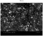
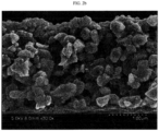
- Example 1 The surfaces and sections of the separators according to Example 1, Example 2 and Comparative Example 1 were photographed by scanning electron microscopy (SEM) and the images are shown in FIG. 2a / FIG. 2b , FIG. 3a / FIG. 3b , and FIG. 4a / FIG. 4b .
- SEM scanning electron microscopy
- the acrylic resin binder allows the organic particles to be bound with each other to form an electrode adhesive layer on the surfaces of the separators while realizing adhesion.
- the separator according to Comparative Example 1 through the SEM images that no adhesive layer was formed due to a low content of the acrylic resin binder and the organic particles are introduced to the porous coating layer.
- Example 3 The air permeability of each of Example 3 and Comparative Examples 2-8 was determined by using a digital Oken Type air permeability tester, EGO-IT (Asahi seiko), under a pressure of 0.5 kg/cm 2 for a setting time of 10 seconds. The results are shown in FIG. 5 .
Landscapes
- Chemical & Material Sciences (AREA)
- Chemical Kinetics & Catalysis (AREA)
- Electrochemistry (AREA)
- General Chemical & Material Sciences (AREA)
- Engineering & Computer Science (AREA)
- Inorganic Chemistry (AREA)
- Manufacturing & Machinery (AREA)
- Materials Engineering (AREA)
- Composite Materials (AREA)
- Cell Separators (AREA)
- Electric Double-Layer Capacitors Or The Like (AREA)
- Hybrid Cells (AREA)
Claims (9)
- Separator für eine elektrochemische Vorrichtung, umfassend:ein poröses Polymersubstrat;eine poröse Beschichtungsschicht, die auf mindestens einer Oberfläche des porösen Polymersubstrats gebildet ist und anorganische Partikel und ein Bindemittelpolymer enthält; undeine Elektrodenhaftschicht, die auf der porösen Beschichtungsschicht gebildet ist und eine äußerste Schicht des Separators bildet, wobei die Elektrodenhaftschicht organische Partikel und ein Acrylharzbindemittel enthält, worin das Acrylharzbindemittel in einer Menge von 30-80 Gew.-%, bezogen auf das kombinierte Gewicht der organischen Partikel und des Acrylharzbindemittels, vorhanden ist;worin die Elektrodenhaftschicht in einer Filmform auf mindestens 20% der Oberflächenfläche des Separators gebildet ist; undworin Hohlräume zwischen den organischen Partikeln in der Elektrodenhaftschicht vorhanden sind.
- Separator gemäß Anspruch 1, worin die organischen Partikel einen durchschnittlichen Durchmesser haben, der kleiner ist als der der Poren, die in der porösen Beschichtungsschicht gebildet sind, die direkt unter der Elektrodenhaftschicht angeordnet ist.
- Separator gemäß Anspruch 1 oder 2, worin die organischen Partikel eines oder mehrere aus Polyvinylidenfluorid, Polyvinyldifluorid-co-hexafluorpropylen, Polyvinylidenfluorid-co-trichlorethylen, Polymethylmethacrylat, Polyacrylnitril, Polyvinylacetat, Polyethylen-co-vinylacetat, Polyimid und Polyethylenoxid sind.
- Separator gemäß einem der vorhergehenden Ansprüche, worin die organischen Partikel einen durchschnittlichen Partikeldurchmesser von 0,05 bis 0,5 µm aufweisen.
- Separator gemäß einem der vorhergehenden Ansprüche, worin das Acrylharzbindemittel eine Glasübergangstemperatur von -50 bis 60°C aufweist.
- Separator gemäß einem der vorhergehenden Ansprüche, worin das Acrylharzbindemittel eines oder mehrere aus Ethylacrylat-Acrylsäure-N,N-Dimethylacrylamid-Copolymer, Ethylacrylat-Acrylsäure-2-(Dimethylamino)ethylacrylat-Copolymer, Ethylacrylat-Acrylsäure-N,N-Diethylacrylamid-Copolymer und Ethylacrylat-Acrylsäure-2-(Diethylamino)ethylacrylat-Copolymer ist.
- Separator gemäß einem der vorhergehenden Ansprüche, worin die Elektrodenhaftschicht eine Dicke von 0,01 bis 1,0 µm aufweist.
- Elektrochemische Vorrichtung, umfassend eine Positivelektrode, eine Negativelektrode und einen zwischen der Positivelektrode und der Negativelektrode angeordneten Separator, worin der Separator ein in einem der vorhergehenden Ansprüche definierter Separator ist.
- Elektrochemische Vorrichtung gemäß Anspruch 8, die eine Lithiumsekundärbatterie ist.
Priority Applications (1)
| Application Number | Priority Date | Filing Date | Title |
|---|---|---|---|
| EP25165314.3A EP4550505A3 (de) | 2015-11-11 | 2016-11-11 | Separator mit elektrodenhaftschicht und elektrochemische vorrichtung damit |
Applications Claiming Priority (3)
| Application Number | Priority Date | Filing Date | Title |
|---|---|---|---|
| KR20150158322 | 2015-11-11 | ||
| KR20150158312 | 2015-11-11 | ||
| PCT/KR2016/012999 WO2017082671A1 (ko) | 2015-11-11 | 2016-11-11 | 전극접착층을 구비한 세퍼레이터 및 이를 포함하는 전기화학소자 |
Related Child Applications (2)
| Application Number | Title | Priority Date | Filing Date |
|---|---|---|---|
| EP25165314.3A Division EP4550505A3 (de) | 2015-11-11 | 2016-11-11 | Separator mit elektrodenhaftschicht und elektrochemische vorrichtung damit |
| EP25165314.3A Division-Into EP4550505A3 (de) | 2015-11-11 | 2016-11-11 | Separator mit elektrodenhaftschicht und elektrochemische vorrichtung damit |
Publications (3)
| Publication Number | Publication Date |
|---|---|
| EP3349270A1 EP3349270A1 (de) | 2018-07-18 |
| EP3349270A4 EP3349270A4 (de) | 2018-08-22 |
| EP3349270B1 true EP3349270B1 (de) | 2025-06-04 |
Family
ID=58695751
Family Applications (2)
| Application Number | Title | Priority Date | Filing Date |
|---|---|---|---|
| EP16864597.6A Active EP3349270B1 (de) | 2015-11-11 | 2016-11-11 | Separator mit elektrodenklebeschicht und elektrochemische vorrichtung damit |
| EP25165314.3A Pending EP4550505A3 (de) | 2015-11-11 | 2016-11-11 | Separator mit elektrodenhaftschicht und elektrochemische vorrichtung damit |
Family Applications After (1)
| Application Number | Title | Priority Date | Filing Date |
|---|---|---|---|
| EP25165314.3A Pending EP4550505A3 (de) | 2015-11-11 | 2016-11-11 | Separator mit elektrodenhaftschicht und elektrochemische vorrichtung damit |
Country Status (8)
| Country | Link |
|---|---|
| US (1) | US10991926B2 (de) |
| EP (2) | EP3349270B1 (de) |
| KR (1) | KR102134424B1 (de) |
| CN (1) | CN108352482B (de) |
| ES (1) | ES3033707T3 (de) |
| HU (1) | HUE071713T2 (de) |
| PL (1) | PL3349270T3 (de) |
| WO (1) | WO2017082671A1 (de) |
Families Citing this family (29)
| Publication number | Priority date | Publication date | Assignee | Title |
|---|---|---|---|---|
| KR102005870B1 (ko) * | 2016-01-15 | 2019-07-31 | 삼성에스디아이 주식회사 | 이차 전지용 세퍼레이터 및 이를 포함하는 리튬 이차 전지 |
| JP6536524B2 (ja) * | 2016-10-03 | 2019-07-03 | トヨタ自動車株式会社 | セパレータ一体電極板、及びこれを用いた蓄電素子 |
| CN110832672B (zh) * | 2017-10-20 | 2023-05-05 | 株式会社Lg新能源 | 隔板以及包括该隔板的电化学装置 |
| WO2019130994A1 (ja) * | 2017-12-27 | 2019-07-04 | 帝人株式会社 | 非水系二次電池用セパレータ及び非水系二次電池 |
| WO2019131193A1 (ja) * | 2017-12-27 | 2019-07-04 | パナソニックIpマネジメント株式会社 | 非水電解質二次電池 |
| KR102279515B1 (ko) | 2018-09-03 | 2021-07-20 | 삼성에스디아이 주식회사 | 리튬 이차 전지용 분리막 및 이를 포함하는 리튬 이차 전지 |
| US12562319B2 (en) * | 2018-09-12 | 2026-02-24 | Lg Chem, Ltd. | Separator for electrochemical device and method for manufacturing the same |
| KR102654789B1 (ko) * | 2018-10-23 | 2024-04-05 | 에스케이이노베이션 주식회사 | 이차전지용 분리막 및 이를 이용한 전기화학소자 |
| US20220029243A1 (en) * | 2018-12-26 | 2022-01-27 | Panasonic Intellectual Property Management Co., Ltd. | Non-aqueous electrolyte secondary battery |
| KR102331720B1 (ko) | 2019-02-18 | 2021-11-26 | 삼성에스디아이 주식회사 | 분리막 및 이를 채용한 리튬전지 |
| WO2021020887A1 (ko) * | 2019-07-30 | 2021-02-04 | 주식회사 엘지화학 | 전기화학소자용 복합 분리막 및 이를 포함하는 전기화학소자 |
| KR102827884B1 (ko) * | 2019-12-13 | 2025-06-30 | 주식회사 엘지에너지솔루션 | 고상-액상 하이브리드 전해질 막, 이의 제조방법 및 이를 포함하는 리튬 이차 전지 |
| KR102629464B1 (ko) | 2020-04-13 | 2024-01-25 | 삼성에스디아이 주식회사 | 세퍼레이터 및 이를 채용한 리튬 전지 |
| EP4152509B1 (de) | 2020-07-20 | 2025-11-12 | LG Energy Solution, Ltd. | Separator für sekundärbatterie, herstellungsverfahren dafür, verfahren zur herstellung einer sekundärbatterie mit dem separator und sekundärbatterie, die nach dem verfahren hergestellt ist |
| WO2022031131A1 (ko) * | 2020-08-07 | 2022-02-10 | 주식회사 엘지에너지솔루션 | 이차전지용 분리막 및 이를 포함하는 이차전지 |
| CN114361710B (zh) * | 2020-09-29 | 2025-02-07 | 宁德新能源科技有限公司 | 一种隔离膜、包含该隔离膜的电化学装置及电子装置 |
| KR102442905B1 (ko) * | 2020-11-20 | 2022-09-15 | 더블유스코프코리아 주식회사 | 전극 접착층을 가지는 분리막 및 이를 포함하는 전기화학소자 |
| KR20220143465A (ko) * | 2021-04-16 | 2022-10-25 | 삼성에스디아이 주식회사 | 리튬 이차 전지용 분리막, 이를 포함하는 리튬 이차 전지, 및 상기 리튬 이차 전지용 분리막의 제조방법 |
| CN113675531A (zh) * | 2021-07-13 | 2021-11-19 | 宁德新能源科技有限公司 | 隔离膜、锂离子电芯及用电装置 |
| KR20230054149A (ko) * | 2021-10-15 | 2023-04-24 | 삼성에스디아이 주식회사 | 전극 조립체 및 이를 포함하는 리튬 이차 전지 |
| CN114156596B (zh) * | 2021-12-03 | 2023-08-22 | 东莞市魔方新能源科技有限公司 | 一种锂离子电池用隔膜及含该隔膜的锂离子电池 |
| CN115249870B (zh) * | 2022-01-13 | 2023-11-14 | 青岛大学 | 一种海藻纤维的改性方法及其在锂离子电池隔膜中的应用 |
| KR102594964B1 (ko) * | 2022-05-26 | 2023-10-26 | 주식회사 엘지에너지솔루션 | 유기/무기 복합 다공성 코팅층을 포함하는 전기화학소자용 분리막 및 이를 포함하는 전기화학소자 |
| KR102619394B1 (ko) * | 2022-08-11 | 2023-12-29 | 주식회사 엘지에너지솔루션 | 전기화학소자용 분리막의 제조 방법 |
| KR102631754B1 (ko) | 2022-09-06 | 2024-01-31 | 주식회사 엘지에너지솔루션 | 전기화학소자용 분리막 및 이를 구비하는 전기화학소자 |
| US20250316840A1 (en) * | 2023-01-20 | 2025-10-09 | Lg Energy Solution, Ltd. | Electrochemical device separator, manufacturing method therefor and electrochemical device comprising same |
| WO2024181689A1 (ko) * | 2023-02-28 | 2024-09-06 | 주식회사 엘지에너지솔루션 | 전기화학소자용 분리막 및 이를 포함하는 전기화학소자 |
| WO2024181688A1 (ko) * | 2023-02-28 | 2024-09-06 | 주식회사 엘지에너지솔루션 | 전기화학소자용 분리막, 이를 포함하는 전기화학소자 및 이의 제조하는 방법 |
| KR20240156158A (ko) * | 2023-04-21 | 2024-10-29 | 주식회사 엘지에너지솔루션 | 전기화학소자용 분리막 및 이를 포함하는 전기화학소자 |
Family Cites Families (25)
| Publication number | Priority date | Publication date | Assignee | Title |
|---|---|---|---|---|
| CN101292378B (zh) * | 2005-10-18 | 2010-11-03 | 东丽株式会社 | 蓄电装置隔离物用微多孔膜以及使用该膜的蓄电装置隔离物 |
| HUE043623T2 (hu) | 2009-09-30 | 2019-08-28 | Zeon Corp | Porózus membrán újratölthetõ telephez, valamint újratölthetõ telep |
| WO2012043729A1 (ja) * | 2010-09-30 | 2012-04-05 | 日本ゼオン株式会社 | 二次電池多孔膜スラリー、二次電池多孔膜、二次電池電極、二次電池セパレーター、二次電池、及び二次電池多孔膜の製造方法 |
| KR101367754B1 (ko) | 2011-07-07 | 2014-02-27 | 주식회사 엘지화학 | 전기화학소자용 전극 조립체 및 이를 구비한 전기화학소자 |
| TWI467833B (zh) | 2011-07-20 | 2015-01-01 | Lg Chemical Ltd | 隔離膜、其之製造方法及包含其之電化學裝置 |
| WO2013058421A1 (ko) * | 2011-10-20 | 2013-04-25 | 주식회사 엘지화학 | 세퍼레이터의 제조방법, 이로부터 형성된 세퍼레이터 및 이를 구비한 전기화학소자 |
| CN103947009B (zh) | 2011-11-15 | 2016-03-09 | 帝人株式会社 | 非水系二次电池用隔膜及其制造方法以及非水系二次电池 |
| KR101369326B1 (ko) * | 2011-12-27 | 2014-03-04 | 주식회사 엘지화학 | 세퍼레이터의 제조방법 및 이에 따라 제조된 세퍼레이터를 구비한 전기화학소자 |
| US9887406B2 (en) | 2012-03-09 | 2018-02-06 | Teijin Limited | Separator for non-aqueous secondary battery, method for manufacturing the same, and non-aqueous secondary battery |
| US9941497B2 (en) | 2012-04-05 | 2018-04-10 | Zeon Corporation | Separator for secondary cell |
| KR101535198B1 (ko) | 2012-06-04 | 2015-07-08 | 주식회사 엘지화학 | 접착력이 개선된 전기화학소자용 분리막 및 그의 제조방법 |
| JP5464766B2 (ja) * | 2012-07-20 | 2014-04-09 | 日立マクセル株式会社 | 電池用セパレータおよび非水電解液電池 |
| WO2014030507A1 (ja) * | 2012-08-23 | 2014-02-27 | Jnc株式会社 | 耐熱性に優れた複合多孔質膜 |
| KR101662638B1 (ko) * | 2012-10-22 | 2016-10-05 | 주식회사 엘지화학 | 바인더층을 갖는 분리막, 상기 분리막을 포함하는 전기화학소자, 및 상기 분리막의 제조방법 |
| JP6314832B2 (ja) * | 2012-11-26 | 2018-04-25 | 日本ゼオン株式会社 | 電極/セパレータ積層体の製造方法およびリチウムイオン二次電池 |
| JP6186783B2 (ja) * | 2013-03-19 | 2017-08-30 | ソニー株式会社 | セパレータ、電池、電池パック、電子機器、電動車両、蓄電装置および電力システム |
| US10038174B2 (en) | 2013-04-16 | 2018-07-31 | Samsung Sdi Co., Ltd. | Separator and lithium battery including the separator |
| KR102209823B1 (ko) | 2013-04-16 | 2021-01-29 | 삼성에스디아이 주식회사 | 세퍼레이터 및 이를 채용한 리튬전지 |
| EP3046163B1 (de) * | 2013-09-10 | 2020-07-22 | Toray Industries, Inc. | Separator für sekundärzelle und sekundärzelle |
| JP2015063428A (ja) * | 2013-09-25 | 2015-04-09 | 株式会社Nicher | エアゾール容器入り有機質肥料 |
| JP6409782B2 (ja) | 2013-10-31 | 2018-10-24 | 日本ゼオン株式会社 | リチウムイオン二次電池のバインダー用の粒子状重合体、接着層及び多孔膜組成物 |
| KR20150057481A (ko) * | 2013-11-19 | 2015-05-28 | 삼성에스디아이 주식회사 | 리튬 전지용 세퍼레이터, 이를 포함하는 리튬 전지, 및 상기 리튬 전지의 제조방법 |
| JP6263611B2 (ja) * | 2013-12-17 | 2018-01-17 | エルジー・ケム・リミテッド | 電気化学素子用分離膜 |
| US10002719B2 (en) * | 2014-04-21 | 2018-06-19 | Lg Chem, Ltd. | Separator having binder layer, and electrochemical device comprising the separator and method of preparing the separator |
| US10734627B2 (en) * | 2016-04-01 | 2020-08-04 | Lg Chen, Ltd. | Separator comprising an adhesion layer for an electrochemical device and an electrode assembly comprising the same |
-
2016
- 2016-11-11 EP EP16864597.6A patent/EP3349270B1/de active Active
- 2016-11-11 PL PL16864597.6T patent/PL3349270T3/pl unknown
- 2016-11-11 KR KR1020160150284A patent/KR102134424B1/ko active Active
- 2016-11-11 EP EP25165314.3A patent/EP4550505A3/de active Pending
- 2016-11-11 US US15/768,176 patent/US10991926B2/en active Active
- 2016-11-11 CN CN201680065456.3A patent/CN108352482B/zh active Active
- 2016-11-11 HU HUE16864597A patent/HUE071713T2/hu unknown
- 2016-11-11 WO PCT/KR2016/012999 patent/WO2017082671A1/ko not_active Ceased
- 2016-11-11 ES ES16864597T patent/ES3033707T3/es active Active
Also Published As
| Publication number | Publication date |
|---|---|
| EP4550505A2 (de) | 2025-05-07 |
| PL3349270T3 (pl) | 2025-08-04 |
| KR20170055440A (ko) | 2017-05-19 |
| KR102134424B1 (ko) | 2020-07-15 |
| WO2017082671A1 (ko) | 2017-05-18 |
| EP4550505A3 (de) | 2025-05-21 |
| US10991926B2 (en) | 2021-04-27 |
| EP3349270A4 (de) | 2018-08-22 |
| ES3033707T3 (en) | 2025-08-07 |
| EP3349270A1 (de) | 2018-07-18 |
| CN108352482B (zh) | 2021-09-10 |
| US20180315971A1 (en) | 2018-11-01 |
| CN108352482A (zh) | 2018-07-31 |
| HUE071713T2 (hu) | 2025-09-28 |
Similar Documents
| Publication | Publication Date | Title |
|---|---|---|
| EP3349270B1 (de) | Separator mit elektrodenklebeschicht und elektrochemische vorrichtung damit | |
| EP4184641B1 (de) | Separator und elektrochemische vorrichtung damit | |
| US10916754B2 (en) | Separator having porous coating layer, method for manufacturing the same and electrochemical device having the same | |
| EP2328220B1 (de) | Separator mit poröser beschichtung, herstellungsverfahren dafür und elektrochemische vorrichtung damit | |
| EP2248209B1 (de) | Separator aufweisend eine verbesserte haftung an eine elektrode und eine elektrochemische zelle damit | |
| EP2750219B1 (de) | Verfahren zur herstellung eines abscheiders, damit hergestellter abscheider und elektrochemische vorrichtung damit | |
| EP1958277B1 (de) | Elektrode mit verbesserter sicherheit und elektrochemische einrichtung damit | |
| EP3675227A1 (de) | Separator und elektrochemische vorrichtung damit | |
| EP4601102A2 (de) | Separator und elektrochemische vorrichtung damit | |
| EP3671899B1 (de) | Verfahren zur herstellung eines separators, dadurch geformter separator und elektrochemische vorrichtung damit | |
| EP2894698B1 (de) | Elektrodenstruktur mit isolationsschicht, verfahren zur herstellung davon und elektrochemisches element damit | |
| US20250158220A1 (en) | Method for Manufacturing Separator, Separator Obtained Therefrom and Electrochemical Device Including the Same | |
| EP4142034A1 (de) | Verfahren und vorrichtung zur herstellung eines separators und so hergestellter separator |
Legal Events
| Date | Code | Title | Description |
|---|---|---|---|
| STAA | Information on the status of an ep patent application or granted ep patent |
Free format text: STATUS: THE INTERNATIONAL PUBLICATION HAS BEEN MADE |
|
| PUAI | Public reference made under article 153(3) epc to a published international application that has entered the european phase |
Free format text: ORIGINAL CODE: 0009012 |
|
| STAA | Information on the status of an ep patent application or granted ep patent |
Free format text: STATUS: REQUEST FOR EXAMINATION WAS MADE |
|
| 17P | Request for examination filed |
Effective date: 20180410 |
|
| AK | Designated contracting states |
Kind code of ref document: A1 Designated state(s): AL AT BE BG CH CY CZ DE DK EE ES FI FR GB GR HR HU IE IS IT LI LT LU LV MC MK MT NL NO PL PT RO RS SE SI SK SM TR |
|
| AX | Request for extension of the european patent |
Extension state: BA ME |
|
| A4 | Supplementary search report drawn up and despatched |
Effective date: 20180725 |
|
| RIC1 | Information provided on ipc code assigned before grant |
Ipc: H01M 2/16 20060101AFI20180719BHEP Ipc: H01M 10/052 20100101ALI20180719BHEP |
|
| DAV | Request for validation of the european patent (deleted) | ||
| DAX | Request for extension of the european patent (deleted) | ||
| STAA | Information on the status of an ep patent application or granted ep patent |
Free format text: STATUS: EXAMINATION IS IN PROGRESS |
|
| 17Q | First examination report despatched |
Effective date: 20201210 |
|
| RAP1 | Party data changed (applicant data changed or rights of an application transferred) |
Owner name: LG ENERGY SOLUTION LTD. |
|
| RAP3 | Party data changed (applicant data changed or rights of an application transferred) |
Owner name: LG ENERGY SOLUTION, LTD. |
|
| REG | Reference to a national code |
Ref country code: DE Ref legal event code: R079 Free format text: PREVIOUS MAIN CLASS: H01M0002160000 Ipc: H01M0050417000 Ref document number: 602016092487 Country of ref document: DE |
|
| RIC1 | Information provided on ipc code assigned before grant |
Ipc: H01M 10/052 20100101ALI20241129BHEP Ipc: H01M 50/457 20210101ALI20241129BHEP Ipc: H01M 50/451 20210101ALI20241129BHEP Ipc: H01M 50/443 20210101ALI20241129BHEP Ipc: H01M 50/429 20210101ALI20241129BHEP Ipc: H01M 50/426 20210101ALI20241129BHEP Ipc: H01M 50/42 20210101ALI20241129BHEP Ipc: H01M 50/417 20210101AFI20241129BHEP |
|
| GRAP | Despatch of communication of intention to grant a patent |
Free format text: ORIGINAL CODE: EPIDOSNIGR1 |
|
| STAA | Information on the status of an ep patent application or granted ep patent |
Free format text: STATUS: GRANT OF PATENT IS INTENDED |
|
| INTG | Intention to grant announced |
Effective date: 20250115 |
|
| GRAS | Grant fee paid |
Free format text: ORIGINAL CODE: EPIDOSNIGR3 |
|
| GRAA | (expected) grant |
Free format text: ORIGINAL CODE: 0009210 |
|
| STAA | Information on the status of an ep patent application or granted ep patent |
Free format text: STATUS: THE PATENT HAS BEEN GRANTED |
|
| P01 | Opt-out of the competence of the unified patent court (upc) registered |
Free format text: CASE NUMBER: APP_16762/2025 Effective date: 20250407 |
|
| AK | Designated contracting states |
Kind code of ref document: B1 Designated state(s): AL AT BE BG CH CY CZ DE DK EE ES FI FR GB GR HR HU IE IS IT LI LT LU LV MC MK MT NL NO PL PT RO RS SE SI SK SM TR |
|
| REG | Reference to a national code |
Ref country code: GB Ref legal event code: FG4D |
|
| REG | Reference to a national code |
Ref country code: CH Ref legal event code: EP |
|
| REG | Reference to a national code |
Ref country code: DE Ref legal event code: R096 Ref document number: 602016092487 Country of ref document: DE |
|
| REG | Reference to a national code |
Ref country code: IE Ref legal event code: FG4D |
|
| REG | Reference to a national code |
Ref country code: NL Ref legal event code: FP |
|
| REG | Reference to a national code |
Ref country code: SE Ref legal event code: TRGR |
|
| REG | Reference to a national code |
Ref country code: ES Ref legal event code: FG2A Ref document number: 3033707 Country of ref document: ES Kind code of ref document: T3 Effective date: 20250807 |
|
| REG | Reference to a national code |
Ref country code: HU Ref legal event code: AG4A Ref document number: E071713 Country of ref document: HU |
|
| PG25 | Lapsed in a contracting state [announced via postgrant information from national office to epo] |
Ref country code: FI Free format text: LAPSE BECAUSE OF FAILURE TO SUBMIT A TRANSLATION OF THE DESCRIPTION OR TO PAY THE FEE WITHIN THE PRESCRIBED TIME-LIMIT Effective date: 20250604 |
|
| REG | Reference to a national code |
Ref country code: LT Ref legal event code: MG9D |
|
| PG25 | Lapsed in a contracting state [announced via postgrant information from national office to epo] |
Ref country code: GR Free format text: LAPSE BECAUSE OF FAILURE TO SUBMIT A TRANSLATION OF THE DESCRIPTION OR TO PAY THE FEE WITHIN THE PRESCRIBED TIME-LIMIT Effective date: 20250905 Ref country code: NO Free format text: LAPSE BECAUSE OF FAILURE TO SUBMIT A TRANSLATION OF THE DESCRIPTION OR TO PAY THE FEE WITHIN THE PRESCRIBED TIME-LIMIT Effective date: 20250904 |
|
| PG25 | Lapsed in a contracting state [announced via postgrant information from national office to epo] |
Ref country code: BG Free format text: LAPSE BECAUSE OF FAILURE TO SUBMIT A TRANSLATION OF THE DESCRIPTION OR TO PAY THE FEE WITHIN THE PRESCRIBED TIME-LIMIT Effective date: 20250604 |
|
| PG25 | Lapsed in a contracting state [announced via postgrant information from national office to epo] |
Ref country code: HR Free format text: LAPSE BECAUSE OF FAILURE TO SUBMIT A TRANSLATION OF THE DESCRIPTION OR TO PAY THE FEE WITHIN THE PRESCRIBED TIME-LIMIT Effective date: 20250604 |
|
| PG25 | Lapsed in a contracting state [announced via postgrant information from national office to epo] |
Ref country code: RS Free format text: LAPSE BECAUSE OF FAILURE TO SUBMIT A TRANSLATION OF THE DESCRIPTION OR TO PAY THE FEE WITHIN THE PRESCRIBED TIME-LIMIT Effective date: 20250904 |
|
| PG25 | Lapsed in a contracting state [announced via postgrant information from national office to epo] |
Ref country code: LV Free format text: LAPSE BECAUSE OF FAILURE TO SUBMIT A TRANSLATION OF THE DESCRIPTION OR TO PAY THE FEE WITHIN THE PRESCRIBED TIME-LIMIT Effective date: 20250604 |
|
| PGFP | Annual fee paid to national office [announced via postgrant information from national office to epo] |
Ref country code: NL Payment date: 20251020 Year of fee payment: 10 |
|
| PG25 | Lapsed in a contracting state [announced via postgrant information from national office to epo] |
Ref country code: PT Free format text: LAPSE BECAUSE OF FAILURE TO SUBMIT A TRANSLATION OF THE DESCRIPTION OR TO PAY THE FEE WITHIN THE PRESCRIBED TIME-LIMIT Effective date: 20251006 |
|
| PGFP | Annual fee paid to national office [announced via postgrant information from national office to epo] |
Ref country code: HU Payment date: 20251127 Year of fee payment: 10 |
|
| REG | Reference to a national code |
Ref country code: AT Ref legal event code: MK05 Ref document number: 1801293 Country of ref document: AT Kind code of ref document: T Effective date: 20250604 |
|
| PG25 | Lapsed in a contracting state [announced via postgrant information from national office to epo] |
Ref country code: IS Free format text: LAPSE BECAUSE OF FAILURE TO SUBMIT A TRANSLATION OF THE DESCRIPTION OR TO PAY THE FEE WITHIN THE PRESCRIBED TIME-LIMIT Effective date: 20251004 |
|
| PGFP | Annual fee paid to national office [announced via postgrant information from national office to epo] |
Ref country code: DE Payment date: 20251020 Year of fee payment: 10 |
|
| PGFP | Annual fee paid to national office [announced via postgrant information from national office to epo] |
Ref country code: GB Payment date: 20251023 Year of fee payment: 10 |
|
| PG25 | Lapsed in a contracting state [announced via postgrant information from national office to epo] |
Ref country code: AT Free format text: LAPSE BECAUSE OF FAILURE TO SUBMIT A TRANSLATION OF THE DESCRIPTION OR TO PAY THE FEE WITHIN THE PRESCRIBED TIME-LIMIT Effective date: 20250604 Ref country code: SM Free format text: LAPSE BECAUSE OF FAILURE TO SUBMIT A TRANSLATION OF THE DESCRIPTION OR TO PAY THE FEE WITHIN THE PRESCRIBED TIME-LIMIT Effective date: 20250604 |
|
| PGFP | Annual fee paid to national office [announced via postgrant information from national office to epo] |
Ref country code: IT Payment date: 20251021 Year of fee payment: 10 |
|
| PGFP | Annual fee paid to national office [announced via postgrant information from national office to epo] |
Ref country code: FR Payment date: 20251021 Year of fee payment: 10 |
|
| PGFP | Annual fee paid to national office [announced via postgrant information from national office to epo] |
Ref country code: BE Payment date: 20251020 Year of fee payment: 10 Ref country code: TR Payment date: 20251022 Year of fee payment: 10 |
|
| PGFP | Annual fee paid to national office [announced via postgrant information from national office to epo] |
Ref country code: SE Payment date: 20251021 Year of fee payment: 10 |
|
| PG25 | Lapsed in a contracting state [announced via postgrant information from national office to epo] |
Ref country code: CZ Free format text: LAPSE BECAUSE OF FAILURE TO SUBMIT A TRANSLATION OF THE DESCRIPTION OR TO PAY THE FEE WITHIN THE PRESCRIBED TIME-LIMIT Effective date: 20250604 |
|
| PGFP | Annual fee paid to national office [announced via postgrant information from national office to epo] |
Ref country code: PL Payment date: 20251020 Year of fee payment: 10 |
|
| PG25 | Lapsed in a contracting state [announced via postgrant information from national office to epo] |
Ref country code: EE Free format text: LAPSE BECAUSE OF FAILURE TO SUBMIT A TRANSLATION OF THE DESCRIPTION OR TO PAY THE FEE WITHIN THE PRESCRIBED TIME-LIMIT Effective date: 20250604 |
|
| PG25 | Lapsed in a contracting state [announced via postgrant information from national office to epo] |
Ref country code: SK Free format text: LAPSE BECAUSE OF FAILURE TO SUBMIT A TRANSLATION OF THE DESCRIPTION OR TO PAY THE FEE WITHIN THE PRESCRIBED TIME-LIMIT Effective date: 20250604 Ref country code: RO Free format text: LAPSE BECAUSE OF FAILURE TO SUBMIT A TRANSLATION OF THE DESCRIPTION OR TO PAY THE FEE WITHIN THE PRESCRIBED TIME-LIMIT Effective date: 20250604 |
|
| PGFP | Annual fee paid to national office [announced via postgrant information from national office to epo] |
Ref country code: ES Payment date: 20251215 Year of fee payment: 10 |
|
| REG | Reference to a national code |
Ref country code: DE Ref legal event code: R097 Ref document number: 602016092487 Country of ref document: DE |
|
| PLBE | No opposition filed within time limit |
Free format text: ORIGINAL CODE: 0009261 |
|
| STAA | Information on the status of an ep patent application or granted ep patent |
Free format text: STATUS: NO OPPOSITION FILED WITHIN TIME LIMIT |
|
| PG25 | Lapsed in a contracting state [announced via postgrant information from national office to epo] |
Ref country code: DK Free format text: LAPSE BECAUSE OF FAILURE TO SUBMIT A TRANSLATION OF THE DESCRIPTION OR TO PAY THE FEE WITHIN THE PRESCRIBED TIME-LIMIT Effective date: 20250604 |
|
| REG | Reference to a national code |
Ref country code: CH Ref legal event code: L10 Free format text: ST27 STATUS EVENT CODE: U-0-0-L10-L00 (AS PROVIDED BY THE NATIONAL OFFICE) Effective date: 20260416 |