EP3297540B1 - Minimally invasive surgical suturing device for papillary muscles - Google Patents
Minimally invasive surgical suturing device for papillary muscles Download PDFInfo
- Publication number
- EP3297540B1 EP3297540B1 EP16797289.2A EP16797289A EP3297540B1 EP 3297540 B1 EP3297540 B1 EP 3297540B1 EP 16797289 A EP16797289 A EP 16797289A EP 3297540 B1 EP3297540 B1 EP 3297540B1
- Authority
- EP
- European Patent Office
- Prior art keywords
- suture
- pledget
- legs
- suturing device
- surgical suturing
- Prior art date
- Legal status (The legal status is an assumption and is not a legal conclusion. Google has not performed a legal analysis and makes no representation as to the accuracy of the status listed.)
- Active
Links
Images


Classifications
-
- A—HUMAN NECESSITIES
- A61—MEDICAL OR VETERINARY SCIENCE; HYGIENE
- A61B—DIAGNOSIS; SURGERY; IDENTIFICATION
- A61B17/00—Surgical instruments, devices or methods
- A61B17/04—Surgical instruments, devices or methods for suturing wounds; Holders or packages for needles or suture materials
- A61B17/0482—Needle or suture guides
-
- A—HUMAN NECESSITIES
- A61—MEDICAL OR VETERINARY SCIENCE; HYGIENE
- A61B—DIAGNOSIS; SURGERY; IDENTIFICATION
- A61B17/00—Surgical instruments, devices or methods
- A61B17/04—Surgical instruments, devices or methods for suturing wounds; Holders or packages for needles or suture materials
- A61B17/0469—Suturing instruments for use in minimally invasive surgery, e.g. endoscopic surgery
-
- A—HUMAN NECESSITIES
- A61—MEDICAL OR VETERINARY SCIENCE; HYGIENE
- A61B—DIAGNOSIS; SURGERY; IDENTIFICATION
- A61B17/00—Surgical instruments, devices or methods
- A61B17/04—Surgical instruments, devices or methods for suturing wounds; Holders or packages for needles or suture materials
- A61B17/0401—Suture anchors, buttons or pledgets, i.e. means for attaching sutures to bone, cartilage or soft tissue; Instruments for applying or removing suture anchors
- A61B2017/0406—Pledgets
-
- A—HUMAN NECESSITIES
- A61—MEDICAL OR VETERINARY SCIENCE; HYGIENE
- A61B—DIAGNOSIS; SURGERY; IDENTIFICATION
- A61B17/00—Surgical instruments, devices or methods
- A61B17/04—Surgical instruments, devices or methods for suturing wounds; Holders or packages for needles or suture materials
- A61B17/0469—Suturing instruments for use in minimally invasive surgery, e.g. endoscopic surgery
- A61B2017/0472—Multiple-needled, e.g. double-needled, instruments
Definitions
- the claimed invention relates to surgical suturing, and more specifically to minimally invasive surgical suturing devices for suturing papillary muscles.
- the human heart relies on a series of one-way valves to help control the flow of blood through the chambers of the heart.
- deoxygenated blood returns to the heart 20, via the superior vena cava 22 and the inferior vena cava 24, entering the right atrium 26.
- the heart muscle tissue contracts in a rhythmic, coordinated heartbeat, first with an atrial contraction which aids blood in the right atrium 26 to pass through the tricuspid valve 28 and into the right ventricle 30. Following atrial contraction, ventricular contraction occurs and the tricuspid valve 28 closes.
- Ventricular contraction is stronger than atrial contraction, assisting blood flow through the pulmonic valve 32, out of the heart 20 via the pulmonary artery 34, and to the lungs (not shown) for oxygenation.
- the pulmonic valve 32 closes, preventing the backwards flow of blood from the pulmonary artery 34 into the heart 20.
- Left atrial contraction assists blood in the left atrium 38 to pass through the mitral valve 40 and into the left ventricle 42.
- ensuing ventricular contraction causes mitral valve 40 closure, and pushes oxygenated blood from the left ventricle 42 through the aortic valve 44 and into the aorta 46 where it then circulates throughout the body.
- prolapse of mitral valve 40 is prevented during ventricular contraction by chordae 40A attached between the mitral valve 40 leaflets and papillary muscles 40B.
- the aortic valve 44 closes, preventing the backwards flow of blood from the aorta 46 into the heart 20.
- a person's heart valves 28, 32, 40, and 44 can have or develop problems which adversely affect their function and, consequently, negatively impact the person's health.
- problems with heart valves can be organized into two categories: regurgitation and/or stenosis.
- Regurgitation occurs if a heart valve does not seal tightly, thereby allowing blood to flow back into a chamber rather than advancing through and out of the heart. This can cause the heart to work harder to remain an effective pump. Regurgitation is frequently observed when the mitral valve 40 fails to properly close during a ventricular contraction. Mitral regurgitation can be caused by chordae 40A stretching, tearing, or rupture, along with other structural changes within the heart.
- Neochordal replacement for stretched or torn chordae is one option to reduce regurgitation.
- chords to be replaced are identified and dissected as required.
- a papillary suture is placed in a papillary muscle corresponding to the dissected chord.
- the papillary suture may optionally be pledgeted on one or both sides of the papillary muscle.
- a leaflet suture is also placed in the corresponding mitral valve leaflet. The papillary suture and the leaflet suture may then be tied or otherwise fastened together to create a replacement chord to help support the mitral valve leaflet and prevent regurgitation.
- US 2012/001383 A1 refers to a method and apparatus for closing an opening in thick, moving tissue.
- the apparatus comprises an anatomical variation through which a needle can be guided.
- a pledget may be arranged on a top surface of a tip end of a forked shaft.
- a surgical suturing device has a forked guide tip having a plurality of legs, wherein each of the plurality of legs comprises a proximal end, an anatomical variation, and a distal end.
- a method of chord replacement for a heart valve is also disclosed.
- a suture is placed in a papillary muscle using a surgical suturing device having a forked guide tip and a papillary suture.
- a leaflet suture is placed in a leaflet.
- the papillary suture and the leaflet suture are loaded in a suture fastener from opposite directions in a coaxial fashion.
- the length of the papillary suture and/or the leaflet suture are adjusted relative to the suture fastener to achieve a desired replacement chord length.
- the suture fastener is attached to the papillary suture and the leaflet suture to lock the desired replacement chord length.
- FIG. 2 is a perspective view of a surgical suturing device 48.
- the surgical suturing device 48 may have a housing 50 coupled to a shaft 52.
- a forked guide tip 54 is coupled to an end of the shaft 52, opposite from the housing 48.
- the forked guide tip 54 may be continuous with the shaft 52, rather than a separate assembly piece which is coupled to the shaft 52.
- the surgical suturing device 48 also has a needle actuator 56 which is configured to move two needles (not visible in this view) within the forked guide tip 54 as will be described in greater detail below.
- Some suitable shafts include a straight shaft (as illustrated), a curved shaft, a bent shaft, a flexible shaft, and an articulating shaft.
- Some suitable needle actuators include a handle (as illustrated), a lever, a knob, a slide, a gear, a wheel, a motor, and a solenoid.
- the forked guide tip 54 may have a suture feed opening 58 which can be used to allow a portion of a suture (not shown in this view) to be loaded into at least a portion of the shaft 52 and potentially into and/or out of the housing 50 for the purpose of simplifying suture management.
- the forked guide tip 54 may also have one or more cross-supports 60 extending between individual legs 62, 64 of the forked guide tip 54.
- a distal end 66, 68 of each leg 62, 64, respectively, of the forked guide tip 54 includes a ferrule receiving aperture in alignment with a needle path (not shown in this view, but illustrated farther below) extending from proximal portions 70, 72 of the respective forked guide tip legs 62, 64.
- the fork leg 62 includes an anatomical variation 74.
- the other forked guide tip leg 64 has an anatomical variation 76 between its proximal and distal ends 72, 68.
- the anatomical variations 74, 76 are sized to help guide the forked guide tip 54 onto one or more anatomical structures.
- the anatomical variations 74, 76 include arches sized and shaped to fit on a papillary muscle.
- the openings between the forked legs 62, 64 help to provide visibility to tissue when the anatomical variations are positioned by a surgeon operating the device, for example by manipulating the housing 50 with the attached handle 78.
- the forked legs 62, 64 may also be curved away from a longitudinal axis 80 of the shaft 52 to provide added visibility through the forked area.
- the forked legs 62, 64 are curved in a concave fashion with respect to the longitudinal axis 80 passing over them as illustrated in FIG. 2 .
- FIG. 3 is an exploded perspective view of the surgical suturing device of FIG. 2 without the housing 50 or needle actuator 56.
- Two needle guide tubes 82A, 82B are inserted into respective openings 84A, 84B in multiple supports 86.
- the supports 86 may be distributed evenly or unevenly along the guide tubes 82A, 82B.
- the shaft 52 is hollow and the supports 86 are sized to fit into and be supported by the inside of the shaft 52.
- the forked guide tip 54 attaches to the distal end 88 of the shaft 52 such that the needle guide tubes 82A, 82B align with needle channels (not visible in this view, but discussed below and shown in FIGS. 4A-4E ) in the forked guide tip 54.
- Two needles 90A, 90B can be inserted into respective needle guide tubes 82A, 82B as illustrated in FIG. 3 .
- the supports 86 can also include a suture passage 85 to allow a portion of a suture (not shown in this view), fed into the shaft 52 via the suture feed opening 58, to extend either partially into the shaft 52 or all the way through the shaft 52 and into the housing 50 (not shown in this view).
- FIGS. 4A-4E show top, front, bottom, left side, and right side views, respectively for a forked guide tip 54 for a surgical suturing device.
- the needle channels 92A, 92B can be seen passing from the proximal end 94 of the guide tip 54 through the respective legs 62, 64 of the forked guide tip 54.
- the distal ends 66, 68 of the legs 62, 64 each have a respective ferrule receiving aperture 96A, 96B which will be discussed in more detail further in this specification.
- the suture feed opening 58 can be seen extending through the forked guide tip 54 towards and all the way through the proximal end 94 of the forked guide tip 54.
- the cross supports 60 and the anatomical variations 74, 76 discussed previously, are also shown in one or more views of FIGS. 4A-4E .
- FIGS. 4A-4E show top, front, bottom, left side, and right side views, respectively for a forked guide tip 54 for a surgical suturing device as described above.
- FIG. 5 illustrates a forked guide tip 54 with advantageous and ergonomic dimensions.
- the legs 62, 64 have a substantially concave shape with respect to the longitudinal axis 80 of the shaft.
- the needle channel 92A has a proximal channel axis 81 which is approximately 0.518 cm (0.204 inches) above a tip axis 83.
- the proximal channel axis 81 and the tip axis 83 are substantially parallel.
- the portion of the needle channel 92A corresponding to the proximal channel axis and the portion of the needle channel 92A corresponding to the tip axis 83 are approximately 3.569 cm (1.405 inches) apart when measured in a direction parallel to the proximal channel axis 81.
- the upper curve R2 of the legs 62, 64 has a radius of approximately 7.049 cm (2.775 inches).
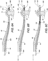
- FIGS. 6A-6C illustrate, in partial cross-sectional view, an example of using a surgical suturing device to place a stitch in tissue, for example, a papillary muscle 108.
- the side view illustrates only a single leg 62, it should be understood that there is a second leg not visible in this view that functions similarly to the shown leg.
- the anatomical variation 74 in conjunction with the end of the leg 62 near the anatomical variation 74 and the distal end 112 of the device form a tissue bite area 98 which may be placed over the tissue in question (in this example, a papillary muscle 108).
- the distal end 112 has a ferrule receiving aperture 96A into which a ferrule 100 has been positioned.
- the ferrule 100 is coupled to a suture 102 which exits from a slot in the distal end 112 of the device.
- the end of the suture 102 opposite the ferrule 100 may terminate in a second ferrule (not shown) that is installed in the ferrule receiving aperture of the second leg (which is not visible in this side view.
- the end of the suture 102 opposite the ferrule 100 may have nothing attached thereto.
- the suture 102 is simply shown as ending at a break line, however, in practice, part of the suture 102 can be fed back through the suture feed opening 58 to help manage the suture 102.
- suture is intended to cover any thread, cable, wire, filament, strand, line, yarn, gut, or similar structure, whether natural and/or synthetic, in monofilament, composite filament, or multifilament form (whether braided, woven, twisted, or otherwise held together), as well as equivalents, substitutions, combinations, and pluralities thereof for such materials and structures.
- a needle 90A is positioned within needle channel 92A in a retracted position.
- the needle 90A has a ferrule-engaging tip 106 which is also configured to be able to penetrate tissue 108.
- an actuator (not shown), coupled to the needle 90A, moves the needle 90A in a distal direction 110, causing the ferrule engaging tip 106 to penetrate the tissue 108 in the tissue bite area 98 as it moves across the tissue bite area 98 and then engages the ferrule 100 held by the ferrule receiving aperture 96A.
- the actuator moves the needle 90A in a proximal direction 114, causing the ferrule-engaging tip 106 and the ferrule 100 which is attached to it to be pulled back across the tissue bite area 98 and through the tissue 108. A portion of the suture 102 is also pulled back through the tissue 108.
- FIGS. 7A-1 to 7G illustrate a method of using the surgical suturing device from FIG. 2 to place a suture 102 in a papillary muscle 108.
- FIG. 7A-1 schematically illustrates a surgical situation. Minimally invasive access has been gained to the left ventricle 42 of the heart. Healthy chordae 40A are coupled between a papillary muscle 40B and leaflets of the mitral valve 40. A pathologic chord has been removed from another papillary muscle 108 and the suturing device is ready to be used. For convenience the shaft, handle, and actuator of the surgical device are not illustrated in these views.
- the device has a forked guide tip 54 having first and second legs.
- the first leg has a proximal end 70, an anatomical variation 74, and a distal end 66.
- the second leg has a proximal end 72, an anatomical variation 76, and a distal end 68.
- the device also has a viewing area 115 defined at least in part by the anatomical variations 74, 76 of the forked guide tip 54.
- a first needle 90A having a suture engaging tip 106A, resides in the first leg in a retracted position.
- a second needle 90B having a suture engaging tip 106B, resides in the second leg in a retracted position.
- a first ferrule 100A is held in the distal end 66 of the first leg, while a second ferrule 100B is held in the distal end 68 of the second leg.
- a suture 102 runs from the first ferrule 100A, through a first hole in a pledget 116, back into the suture feed opening 58, reverses back out of the suture feed opening 58, through a second hole in the pledget 116, and to the second ferrule 100B.
- the pledget 116 rests on part of one or more of the anatomical variations 74, 76. In other examples, the pledget 116 may rest on other portions of the device.
- the pledget 116 has a first face 118 where the end of suture 102 exit the pledget 116 to couple to the ferrules 100A, 100B.
- the tissue bite area 98 is placed over the papillary muscle 108. This can advantageously be done by looking through the viewing area 115 from FIG. 7A-2 .
- the first and second needles 90A, 90B are moved by the actuator (not shown) in a distal direction 110, causing the ferrule engaging tips 106A, 106B to penetrate the tissue 108 in the tissue bite area 98 as they move across the tissue bite area 98 and then engage the respective ferrules 100A, 100B held in the distal ends 66, 68.
- the actuator not shown
- the actuator moves the needles 90A, 90B in a proximal direction 114, causing the ferrule-engaging tips 106A, 106B and the respective ferrules 100A, 100B which are attached to them to be pulled back through the tissue 108. Portions of the suture 102 are also pulled back through the tissue 108. As the suture 102 is pulled through the tissue 108, the pledget 116 may start to pivot 122 off the end of the device so that the first side 118 of the pledget 116 starts to face the tissue 108. A second side 120 of the pledget 116 is located opposite the first side 118 of the pledget 116. As the suture 102 is pulled back through the tissue 108, the suture 102 starts to play out of the suture feed opening 58.
- the suturing device is pulled away 124 from the papillary muscle 108 and the suture 102 may exit the suture feed opening 58 completely.
- the device may continue to be withdrawn 126 such that the first side of the pledget 118 contacts the tissue 108 as the approximate midpoint 127 of the suture 102 is pulled against the second side 120 of the pledget 116.
- the ferrules 100A, 100B held by the device may then be removed from the ends of the suture 102.
- a pledget 116 may not always be used, the pledget does provide an advantageous interface to help protect the suture stitch from pulling through the tissue.
- the suture ends passing out of the tissue 108 may be threaded through a second pledget 128 so both sides of the papillary muscle are pledgeted as illustrated in FIG. 7G .
- FIGS. 7H-7I illustrate a method of coupling a first suture 102 placed in a papillary muscle 108 (for example, as illustrated in the method of FIGS. 7A-2 to 7G ) and a second suture 130 placed in a valve leaflet 132 to each other using a mechanical fastener to replace a chordae tendinae of the heart.
- FIG. 7H simply shows the second suture 130 after it has been stitched through a leaflet 132 of the mitral valve 40.
- FIG. 7H simply shows the second suture 130 after it has been stitched through a leaflet 132 of the mitral valve 40.
- FIG. 7I illustrates a mechanical fastener 134 which has been fastened to hold a first set of suture ends 136 of the first suture 102 which have been passed up through the mechanical faster 134.
- the mechanical fastener 134 also holds a second set of suture ends 138 of the second suture 130 which have been passed down through the mechanical fastener 134.
- One suitable method for fastening the two sets of suture ends together in this fashion is disclosed in U.S. Patent Application Publication 2014/0276979, published September 18, 2014 for U.S. Patent Application 13/840,481 filed March 15, 2013 .
- FIGS. 8 and 9 illustrate alternatives for using the forked guide tip of FIG. 2 with a pledgeted suture.
- the forked guide tip 140 embodiment of FIG. 8 is similar to previous embodiments, except for the pledget 116 which is rested against a proximal side of the anatomical variations 74, 76.
- the viewing area 142 is defined between the forked legs 62, 64 and the proximal portions of the anatomical variations 74, 76.
- the forked guide tip embodiment of FIG. 9 is similar to previous embodiments, except for the pledget 116 which is rested against the suture feed opening 58. In this embodiment, the viewing area 146 is potentially much larger without the pledget 116 blocking a portion of the view.
- FIGS. 10A-10B illustrate one embodiment of a forked guide tip 148 for a surgical suturing device according to the invention for placing a double-pledgeted suture in a papillary muscle.
- the forked guide tip 148 is similar to previous embodiments in that it includes a first pledget 150 through which the suture 102 is routed before reaching the ferrules in the distal leg ends 66, 68.
- a second pledget 152 is held in a pledget holder 154 adjacent to the tissue bite area 98.
- the second pledget 152 is preferably positioned so that the pledget holes are in alignment with the openings in the legs 62, 64 from which the needles 90A, 90B will extend. As illustrated in FIG.
- the needles 90A, 90B may be advanced 156 out of the legs, through the second pledget 152, across the tissue bite area 98 and into engagement with the ferrules. When the ferrules and suture are pulled back through the tissue bite area, they will then be pulled through the second pledget, thereby double-pledgeting the tissue sutured by the device.
- FIGS. 11A-11B illustrate another embodiment of a forked guide tip 158 for a surgical suturing device according to the invention for placing a double-pledgeted suture in a papillary muscle.
- the forked guide tip 158 is similar to the embodiment of FIG. 10A , except that it also includes pledget hole stabilizers 160A, 160B on the tissue gap 98 side of the pledget holder 154. Since the needles 90A, 90B may tend to push the second pledget 152 out of the pledget holder 154 in some embodiments as they pass through the second pledget 152, the pledget hole stabilizers 160A, 160B may help prevent the movement of the second pledget away from the needles 90A, 90B.
- the pledget hole stabilizers 160A, 160B may also enable the use of a second pledget 152 which does not have pre-formed holes, since the needles 90A, 90B will be able to pierce the second pledget as it held in place by the pledget holder 154 and the pledget hole stabilizers 160A, 160B.
- the needles 90A, 90B may be advanced 162 out of the legs 62, 64, through the second pledget 152, through the pledget hole stabilizers 160A, 160B, across the tissue bite area 98 and into engagement with the ferrules held in the distal ends 66, 68. When the ferrules and suture are pulled back through the tissue bite area 98, they will then be pulled through the second pledget, thereby double-pledgeting the tissue sutured by the device.
- FIG. 12 illustrates a further forked guide tip 164 for a surgical suturing device.
- the embodiment of FIG 12 is similar to previous embodiments, particularly the embodiment of FIG. 2 , however it does not include any cross supports.
- the forked guide tip 164 has first and second legs 166, 168 which are coupled to their respective distal ends 66, 68 by respective first and second anatomical variations 170, 172.
- a viewing area 174 is defined by the combination on one side of the first leg 166, the first anatomical variation 170, and the first distal end 66 and by the combination on the other side of the second leg 168, the second anatomical variation 172, and the second distal end 68.
Landscapes
- Health & Medical Sciences (AREA)
- Life Sciences & Earth Sciences (AREA)
- Surgery (AREA)
- Heart & Thoracic Surgery (AREA)
- Engineering & Computer Science (AREA)
- Biomedical Technology (AREA)
- Nuclear Medicine, Radiotherapy & Molecular Imaging (AREA)
- Medical Informatics (AREA)
- Molecular Biology (AREA)
- Animal Behavior & Ethology (AREA)
- General Health & Medical Sciences (AREA)
- Public Health (AREA)
- Veterinary Medicine (AREA)
- Surgical Instruments (AREA)
Description
- The claimed invention relates to surgical suturing, and more specifically to minimally invasive surgical suturing devices for suturing papillary muscles.
- The human heart relies on a series of one-way valves to help control the flow of blood through the chambers of the heart. For example, referring to
FIG. 1 , deoxygenated blood returns to theheart 20, via thesuperior vena cava 22 and theinferior vena cava 24, entering theright atrium 26. The heart muscle tissue contracts in a rhythmic, coordinated heartbeat, first with an atrial contraction which aids blood in theright atrium 26 to pass through thetricuspid valve 28 and into theright ventricle 30. Following atrial contraction, ventricular contraction occurs and thetricuspid valve 28 closes. Ventricular contraction is stronger than atrial contraction, assisting blood flow through thepulmonic valve 32, out of theheart 20 via thepulmonary artery 34, and to the lungs (not shown) for oxygenation. Following the ventricular contraction, thepulmonic valve 32 closes, preventing the backwards flow of blood from thepulmonary artery 34 into theheart 20. - Oxygenated blood returns to the
heart 20, via thepulmonary veins 36, entering theleft atrium 38. Left atrial contraction assists blood in theleft atrium 38 to pass through themitral valve 40 and into theleft ventricle 42. Following the atrial contraction, ensuing ventricular contraction causesmitral valve 40 closure, and pushes oxygenated blood from theleft ventricle 42 through theaortic valve 44 and into theaorta 46 where it then circulates throughout the body. Under nominal conditions, prolapse ofmitral valve 40 is prevented during ventricular contraction bychordae 40A attached between themitral valve 40 leaflets andpapillary muscles 40B. Following left ventricular contraction, theaortic valve 44 closes, preventing the backwards flow of blood from theaorta 46 into theheart 20. - Unfortunately, one or more of a person's
heart valves mitral valve 40 fails to properly close during a ventricular contraction. Mitral regurgitation can be caused bychordae 40A stretching, tearing, or rupture, along with other structural changes within the heart. - Neochordal replacement for stretched or torn chordae is one option to reduce regurgitation. In such a procedure, chords to be replaced are identified and dissected as required. A papillary suture is placed in a papillary muscle corresponding to the dissected chord. The papillary suture may optionally be pledgeted on one or both sides of the papillary muscle. A leaflet suture is also placed in the corresponding mitral valve leaflet. The papillary suture and the leaflet suture may then be tied or otherwise fastened together to create a replacement chord to help support the mitral valve leaflet and prevent regurgitation.
- Unfortunately, while neochordal replacement with ePTFE suture is a proven method of mitral valve repair, technical challenges impede its widespread utilization, especially in minimally invasive cardiac surgery. In particular, it is difficult and time consuming to manipulate a suture needle with forceps through a minimally invasive opening to place the sutures for neochordal replacement. An innovative system that remotely delivers and reliably secures ePTFE suture (or any other desired suture) would dramatically improve the accessibility and clinical outcomes following neochordal implantation.
US 2012/001383 A1 refers to a method and apparatus for closing an opening in thick, moving tissue. The apparatus comprises an anatomical variation through which a needle can be guided. A pledget may be arranged on a top surface of a tip end of a forked shaft. - Therefore, there is a need for an efficient and precise minimally invasive surgical suturing device that enables surgeons to utilize a minimal invasive entry point for neochordal replacement without sacrificing suturing effectiveness.
- The objective is solved by the surgical suturing device of
claim 1. The dependent claims describe preferred embodiments of the invention. - A surgical suturing device is disclosed. The surgical suturing device has a forked guide tip having a plurality of legs, wherein each of the plurality of legs comprises a proximal end, an anatomical variation, and a distal end. A method of chord replacement for a heart valve is also disclosed. A suture is placed in a papillary muscle using a surgical suturing device having a forked guide tip and a papillary suture. A leaflet suture is placed in a leaflet. The papillary suture and the leaflet suture are loaded in a suture fastener from opposite directions in a coaxial fashion. The length of the papillary suture and/or the leaflet suture are adjusted relative to the suture fastener to achieve a desired replacement chord length. The suture fastener is attached to the papillary suture and the leaflet suture to lock the desired replacement chord length.
-
-
FIG. 1 is a cross-sectional view of a heart, illustrating the chambers and valves which function therein. -
FIG. 2 is a perspective view of a surgical suturing device. -
FIG. 3 is an exploded perspective view of the surgical suturing device ofFIG. 2 without the housing or needle actuator. -
FIGS. 4A-4E show top, front, bottom, left side, and right side views, respectively for a forked guide tip for a surgical suturing device. -
FIG. 5 illustrates the forked guide tip ofFIG. 4B with advantageous and ergonomic dimensions. -
FIGS. 6A-6C illustrate, in partial cross-sectional view, an example of using a surgical suturing device to place a stitch in tissue, for example, a papillary muscle. -
FIGS. 7A-1 to 7G illustrate a method of using the surgical suturing device fromFIG. 2 to place a suture in a papillary muscle. -
FIGS. 7H-7I illustrate a method of coupling a first suture placed in a papillary muscle and a second suture placed in a valve leaflet to each other using a mechanical fastener to replace a chordae tendinae of the heart. -
FIGS. 8 and 9 illustrate alternatives for using the forked guide tip ofFIG. 2 with a pledgeted suture. -
FIGS. 10A-10B illustrate one embodiment of a forked guide tip for a surgical suturing device according to the invention for placing a double-pledgeted suture in a papillary muscle. -
FIGS. 11A-11B illustrate another embodiment of a forked guide tip for a surgical suturing device according to the invention for placing a double-pledgeted suture in a papillary muscle. -
FIG. 12 illustrates a further forked guide tip for a surgical suturing device. - It will be appreciated that for purposes of clarity and where deemed appropriate, reference numerals have been repeated in the figures to indicate corresponding features, and that the various elements in the drawings have not necessarily been drawn to scale in order to better show the features.
-
FIG. 2 is a perspective view of asurgical suturing device 48. Thesurgical suturing device 48 may have ahousing 50 coupled to ashaft 52. A forkedguide tip 54 is coupled to an end of theshaft 52, opposite from thehousing 48. The forkedguide tip 54 may be continuous with theshaft 52, rather than a separate assembly piece which is coupled to theshaft 52. Thesurgical suturing device 48 also has aneedle actuator 56 which is configured to move two needles (not visible in this view) within the forkedguide tip 54 as will be described in greater detail below. Some suitable shafts include a straight shaft (as illustrated), a curved shaft, a bent shaft, a flexible shaft, and an articulating shaft. Some suitable needle actuators include a handle (as illustrated), a lever, a knob, a slide, a gear, a wheel, a motor, and a solenoid. - The forked
guide tip 54 may have asuture feed opening 58 which can be used to allow a portion of a suture (not shown in this view) to be loaded into at least a portion of theshaft 52 and potentially into and/or out of thehousing 50 for the purpose of simplifying suture management. The forkedguide tip 54 may also have one or more cross-supports 60 extending betweenindividual legs guide tip 54. Adistal end leg guide tip 54, includes a ferrule receiving aperture in alignment with a needle path (not shown in this view, but illustrated farther below) extending fromproximal portions guide tip legs - Between the proximal and distal ends 70, 66 of the forked
guide tip leg 62, thefork leg 62 includes ananatomical variation 74. Similarly, the other forkedguide tip leg 64 has ananatomical variation 76 between its proximal and distal ends 72, 68. Theanatomical variations guide tip 54 onto one or more anatomical structures. In the illustrated embodiment, theanatomical variations legs housing 50 with the attachedhandle 78. The forkedlegs longitudinal axis 80 of theshaft 52 to provide added visibility through the forked area. In an embodiment, the forkedlegs longitudinal axis 80 passing over them as illustrated inFIG. 2 . -
FIG. 3 is an exploded perspective view of the surgical suturing device ofFIG. 2 without thehousing 50 orneedle actuator 56. Twoneedle guide tubes respective openings multiple supports 86. The supports 86 may be distributed evenly or unevenly along theguide tubes shaft 52 is hollow and thesupports 86 are sized to fit into and be supported by the inside of theshaft 52. The forkedguide tip 54 attaches to thedistal end 88 of theshaft 52 such that theneedle guide tubes FIGS. 4A-4E ) in the forkedguide tip 54. Twoneedles needle guide tubes FIG. 3 . The supports 86 can also include asuture passage 85 to allow a portion of a suture (not shown in this view), fed into theshaft 52 via thesuture feed opening 58, to extend either partially into theshaft 52 or all the way through theshaft 52 and into the housing 50 (not shown in this view). -
FIGS. 4A-4E show top, front, bottom, left side, and right side views, respectively for a forkedguide tip 54 for a surgical suturing device. Theneedle channels proximal end 94 of theguide tip 54 through therespective legs guide tip 54. The distal ends 66, 68 of thelegs ferrule receiving aperture suture feed opening 58 can be seen extending through the forkedguide tip 54 towards and all the way through theproximal end 94 of the forkedguide tip 54. The cross supports 60 and theanatomical variations FIGS. 4A-4E . -
FIGS. 4A-4E show top, front, bottom, left side, and right side views, respectively for a forkedguide tip 54 for a surgical suturing device as described above. - A forked guide tip can be manufactured with a wide range of dimensions.
FIG. 5 illustrates a forkedguide tip 54 with advantageous and ergonomic dimensions. InFIG. 5 , thelegs longitudinal axis 80 of the shaft. Theneedle channel 92A has aproximal channel axis 81 which is approximately 0.518 cm (0.204 inches) above atip axis 83. Theproximal channel axis 81 and thetip axis 83 are substantially parallel. The portion of theneedle channel 92A corresponding to the proximal channel axis and the portion of theneedle channel 92A corresponding to thetip axis 83 are approximately 3.569 cm (1.405 inches) apart when measured in a direction parallel to theproximal channel axis 81. The upper curve R2 of thelegs -
FIGS. 6A-6C illustrate, in partial cross-sectional view, an example of using a surgical suturing device to place a stitch in tissue, for example, apapillary muscle 108. Although the side view illustrates only asingle leg 62, it should be understood that there is a second leg not visible in this view that functions similarly to the shown leg. Theanatomical variation 74, in conjunction with the end of theleg 62 near theanatomical variation 74 and thedistal end 112 of the device form atissue bite area 98 which may be placed over the tissue in question (in this example, a papillary muscle 108). Thedistal end 112 has aferrule receiving aperture 96A into which aferrule 100 has been positioned. Theferrule 100 is coupled to asuture 102 which exits from a slot in thedistal end 112 of the device. The end of thesuture 102 opposite theferrule 100 may terminate in a second ferrule (not shown) that is installed in the ferrule receiving aperture of the second leg (which is not visible in this side view. Alternatively, the end of thesuture 102 opposite theferrule 100 may have nothing attached thereto. For simplicity in the views ofFIGS. 6A-6C , thesuture 102 is simply shown as ending at a break line, however, in practice, part of thesuture 102 can be fed back through thesuture feed opening 58 to help manage thesuture 102. It should be understood that the term "suture", as used herein, is intended to cover any thread, cable, wire, filament, strand, line, yarn, gut, or similar structure, whether natural and/or synthetic, in monofilament, composite filament, or multifilament form (whether braided, woven, twisted, or otherwise held together), as well as equivalents, substitutions, combinations, and pluralities thereof for such materials and structures. - With reference to
FIG. 6A , aneedle 90A is positioned withinneedle channel 92A in a retracted position. Theneedle 90A has a ferrule-engagingtip 106 which is also configured to be able to penetratetissue 108. InFIG. 6B , an actuator (not shown), coupled to theneedle 90A, moves theneedle 90A in adistal direction 110, causing theferrule engaging tip 106 to penetrate thetissue 108 in thetissue bite area 98 as it moves across thetissue bite area 98 and then engages theferrule 100 held by theferrule receiving aperture 96A. InFIG. 6C , the actuator moves theneedle 90A in aproximal direction 114, causing the ferrule-engagingtip 106 and theferrule 100 which is attached to it to be pulled back across thetissue bite area 98 and through thetissue 108. A portion of thesuture 102 is also pulled back through thetissue 108. - The utility of such a device and its equivalents is further illustrated with respect to the perspective views of
FIGS. 7A-1 to 7G which better show thedual needles FIGS. 7A-1 to 7G illustrate a method of using the surgical suturing device fromFIG. 2 to place asuture 102 in apapillary muscle 108.FIG. 7A-1 schematically illustrates a surgical situation. Minimally invasive access has been gained to theleft ventricle 42 of the heart.Healthy chordae 40A are coupled between apapillary muscle 40B and leaflets of themitral valve 40. A pathologic chord has been removed from anotherpapillary muscle 108 and the suturing device is ready to be used. For convenience the shaft, handle, and actuator of the surgical device are not illustrated in these views. - The suturing device and the
papillary muscle 108 may be seen more clearly in the enlarged view ofFIG. 7A-2 . As before, the device has a forkedguide tip 54 having first and second legs. The first leg has aproximal end 70, ananatomical variation 74, and adistal end 66. The second leg has aproximal end 72, ananatomical variation 76, and adistal end 68. The device also has aviewing area 115 defined at least in part by theanatomical variations guide tip 54. Afirst needle 90A, having asuture engaging tip 106A, resides in the first leg in a retracted position. Asecond needle 90B, having asuture engaging tip 106B, resides in the second leg in a retracted position. Afirst ferrule 100A is held in thedistal end 66 of the first leg, while asecond ferrule 100B is held in thedistal end 68 of the second leg. Asuture 102 runs from thefirst ferrule 100A, through a first hole in apledget 116, back into thesuture feed opening 58, reverses back out of thesuture feed opening 58, through a second hole in thepledget 116, and to thesecond ferrule 100B. In this example, thepledget 116 rests on part of one or more of theanatomical variations pledget 116 may rest on other portions of the device. Thepledget 116 has afirst face 118 where the end ofsuture 102 exit thepledget 116 to couple to theferrules - As illustrated in
FIG. 7B , thetissue bite area 98 is placed over thepapillary muscle 108. This can advantageously be done by looking through theviewing area 115 fromFIG. 7A-2 . As illustrated inFIG. 7C , the first andsecond needles distal direction 110, causing theferrule engaging tips tissue 108 in thetissue bite area 98 as they move across thetissue bite area 98 and then engage therespective ferrules FIG. 7D , the actuator (not shown) moves theneedles proximal direction 114, causing the ferrule-engagingtips respective ferrules tissue 108. Portions of thesuture 102 are also pulled back through thetissue 108. As thesuture 102 is pulled through thetissue 108, thepledget 116 may start to pivot 122 off the end of the device so that thefirst side 118 of thepledget 116 starts to face thetissue 108. Asecond side 120 of thepledget 116 is located opposite thefirst side 118 of thepledget 116. As thesuture 102 is pulled back through thetissue 108, thesuture 102 starts to play out of thesuture feed opening 58. - In
FIG. 7E , the suturing device is pulled away 124 from thepapillary muscle 108 and thesuture 102 may exit thesuture feed opening 58 completely. As illustrated inFIG. 7F , the device may continue to be withdrawn 126 such that the first side of thepledget 118 contacts thetissue 108 as theapproximate midpoint 127 of thesuture 102 is pulled against thesecond side 120 of thepledget 116. Theferrules suture 102. While apledget 116 may not always be used, the pledget does provide an advantageous interface to help protect the suture stitch from pulling through the tissue. In fact, in some embodiments, the suture ends passing out of thetissue 108 may be threaded through asecond pledget 128 so both sides of the papillary muscle are pledgeted as illustrated inFIG. 7G . -
FIGS. 7H-7I illustrate a method of coupling afirst suture 102 placed in a papillary muscle 108 (for example, as illustrated in the method ofFIGS. 7A-2 to 7G ) and asecond suture 130 placed in avalve leaflet 132 to each other using a mechanical fastener to replace a chordae tendinae of the heart.FIG. 7H simply shows thesecond suture 130 after it has been stitched through aleaflet 132 of themitral valve 40. Those skilled in the art will be familiar with a variety of ways to create this stitch of thesecond suture 130.FIG. 7I illustrates amechanical fastener 134 which has been fastened to hold a first set of suture ends 136 of thefirst suture 102 which have been passed up through the mechanical faster 134. Themechanical fastener 134 also holds a second set of suture ends 138 of thesecond suture 130 which have been passed down through themechanical fastener 134. One suitable method for fastening the two sets of suture ends together in this fashion is disclosed inU.S. Patent Application Publication 2014/0276979, published September 18, 2014 forU.S. Patent Application 13/840,481 filed March 15, 2013 -
FIGS. 8 and 9 illustrate alternatives for using the forked guide tip ofFIG. 2 with a pledgeted suture. The forkedguide tip 140 embodiment ofFIG. 8 is similar to previous embodiments, except for thepledget 116 which is rested against a proximal side of theanatomical variations viewing area 142 is defined between the forkedlegs anatomical variations FIG. 9 is similar to previous embodiments, except for thepledget 116 which is rested against thesuture feed opening 58. In this embodiment, theviewing area 146 is potentially much larger without thepledget 116 blocking a portion of the view. -
FIGS. 10A-10B illustrate one embodiment of a forkedguide tip 148 for a surgical suturing device according to the invention for placing a double-pledgeted suture in a papillary muscle. The forkedguide tip 148 is similar to previous embodiments in that it includes afirst pledget 150 through which thesuture 102 is routed before reaching the ferrules in the distal leg ends 66, 68. In this embodiment, however, asecond pledget 152 is held in apledget holder 154 adjacent to thetissue bite area 98. Thesecond pledget 152 is preferably positioned so that the pledget holes are in alignment with the openings in thelegs needles FIG. 10B , theneedles second pledget 152, across thetissue bite area 98 and into engagement with the ferrules. When the ferrules and suture are pulled back through the tissue bite area, they will then be pulled through the second pledget, thereby double-pledgeting the tissue sutured by the device. -
FIGS. 11A-11B illustrate another embodiment of a forkedguide tip 158 for a surgical suturing device according to the invention for placing a double-pledgeted suture in a papillary muscle. The forkedguide tip 158 is similar to the embodiment ofFIG. 10A , except that it also includespledget hole stabilizers tissue gap 98 side of thepledget holder 154. Since theneedles second pledget 152 out of thepledget holder 154 in some embodiments as they pass through thesecond pledget 152, thepledget hole stabilizers needles pledget hole stabilizers second pledget 152 which does not have pre-formed holes, since theneedles pledget holder 154 and thepledget hole stabilizers FIG. 11B , theneedles legs second pledget 152, through thepledget hole stabilizers tissue bite area 98 and into engagement with the ferrules held in the distal ends 66, 68. When the ferrules and suture are pulled back through thetissue bite area 98, they will then be pulled through the second pledget, thereby double-pledgeting the tissue sutured by the device. -
FIG. 12 illustrates a further forkedguide tip 164 for a surgical suturing device. The embodiment ofFIG 12 is similar to previous embodiments, particularly the embodiment ofFIG. 2 , however it does not include any cross supports. The forkedguide tip 164 has first andsecond legs anatomical variations viewing area 174 is defined by the combination on one side of thefirst leg 166, the firstanatomical variation 170, and the firstdistal end 66 and by the combination on the other side of thesecond leg 168, the secondanatomical variation 172, and the seconddistal end 68. - Various advantages of a minimally invasive surgical suturing device for papillary muscles and methods thereof have been discussed above. Embodiments discussed herein have been described by way of example in this specification. It will be apparent to those skilled in the art that the forgoing detailed disclosure is intended to be presented by way of example only, and is not limiting. Various alterations, improvements, and modifications will occur and are intended to those skilled in the art, though not expressly stated herein. These alterations, improvements, and modifications are intended to be suggested hereby.
Claims (3)
- A surgical suturing device, comprising:a shaft (52);a forked guide tip (148, 158) coupled to the shaft (52) and having a plurality of legs (62, 64), wherein each of the plurality of legs (62, 64) comprises:a proximal end (70, 72) having a substantially concave shape with respect to a longitudinal axis (80) of the shaft (52) such that the forked legs (62, 64) are curved in a concave fashion with respect to the longitudinal axis (80) passing over the forked legs (62, 64);an anatomical variation (74, 76) including an arch sized and shaped to fit on a papillary muscle; anda distal end (66, 68);a plurality of needles (90A, 90B), each of the plurality of needles (90A, 90B) corresponding to a different one of the plurality of legs (62, 64);characterized bya pledget holder (154) located between the proximal end (70, 72) and the anatomical variation (74, 76), the pledget holder holding a pledget (152); andan actuator (56) configured to move the needles (90A, 90B) out of the proximal ends of the legs (62, 64), through the pledget (152) held in the pledget holder (154), and then through a tissue bite area (98) defined by the arch of the anatomical variation (74, 76).
- The surgical suturing device of claim 1, characterized by a plurality of ferrules (100, 100A, 100B), each of the plurality of ferrules (100, 100A, 100B) held in the distal end (66, 68) of corresponding one of the plurality of legs (62, 64).
- The surgical suturing device of claim 2, characterized in that the ferrules (100, 100A, 100B) are coupled to a suture (102, 103).
Applications Claiming Priority (2)
| Application Number | Priority Date | Filing Date | Title |
|---|---|---|---|
| US14/716,803 US10736624B2 (en) | 2014-05-19 | 2015-05-19 | Minimally invasive surgical suturing device for papillary muscles and methods thereof |
| PCT/US2016/033234 WO2016187406A1 (en) | 2015-05-19 | 2016-05-19 | Minimally invasive surgical suturing device for papillary muscles and methods thereof |
Publications (3)
| Publication Number | Publication Date |
|---|---|
| EP3297540A1 EP3297540A1 (en) | 2018-03-28 |
| EP3297540A4 EP3297540A4 (en) | 2019-02-20 |
| EP3297540B1 true EP3297540B1 (en) | 2020-11-04 |
Family
ID=57320988
Family Applications (1)
| Application Number | Title | Priority Date | Filing Date |
|---|---|---|---|
| EP16797289.2A Active EP3297540B1 (en) | 2015-05-19 | 2016-05-19 | Minimally invasive surgical suturing device for papillary muscles |
Country Status (2)
| Country | Link |
|---|---|
| EP (1) | EP3297540B1 (en) |
| WO (1) | WO2016187406A1 (en) |
Families Citing this family (5)
| Publication number | Priority date | Publication date | Assignee | Title |
|---|---|---|---|---|
| US10898181B2 (en) | 2017-03-17 | 2021-01-26 | Cypris Medical, Inc. | Suturing system |
| US10660637B2 (en) | 2018-04-06 | 2020-05-26 | Cypris Medical, Inc. | Suturing system |
| US11033261B2 (en) * | 2018-05-31 | 2021-06-15 | Cypris Medical, Inc. | Suture system |
| US12137899B2 (en) | 2020-05-11 | 2024-11-12 | Cypris Medical, Inc. | Multiple suture placement system |
| AU2022264759B2 (en) * | 2021-04-25 | 2025-06-26 | Pipeline Medical Technologies, Inc. | Pericardial anchoring system |
Family Cites Families (9)
| Publication number | Priority date | Publication date | Assignee | Title |
|---|---|---|---|---|
| US5908428A (en) * | 1997-05-27 | 1999-06-01 | United States Surgical Corporation | Stitching devices for heart valve replacement surgery |
| US7846180B2 (en) * | 1999-06-22 | 2010-12-07 | Ethicon Endo-Surgery, Inc. | Tissue fixation devices and methods of fixing tissue |
| US7879046B2 (en) * | 2001-10-01 | 2011-02-01 | Depuy Mitek, Inc. | Suturing apparatus and method |
| US8979923B2 (en) * | 2002-10-21 | 2015-03-17 | Mitralign, Inc. | Tissue fastening systems and methods utilizing magnetic guidance |
| US20080065120A1 (en) * | 2005-10-31 | 2008-03-13 | Zannis Anthony D | Surgical instrument, kit and method for creating mattress-type stitches |
| US20100023118A1 (en) * | 2008-07-24 | 2010-01-28 | Edwards Lifesciences Corporation | Method and apparatus for repairing or replacing chordae tendinae |
| US9439643B2 (en) * | 2010-06-09 | 2016-09-13 | C.R. Bard, Inc. | Instruments for delivering transfascial sutures, transfascial suture assemblies, and methods of transfascial suturing |
| US8926640B2 (en) * | 2010-07-13 | 2015-01-06 | Lsi Solutions, Inc. | Method and apparatus for closing an opening in thick, moving tissue |
| JP6816002B2 (en) * | 2015-01-23 | 2021-01-20 | ボストン サイエンティフィック サイムド,インコーポレイテッドBoston Scientific Scimed,Inc. | Balloon catheter visualization system, method, and device with pledge |
-
2016
- 2016-05-19 EP EP16797289.2A patent/EP3297540B1/en active Active
- 2016-05-19 WO PCT/US2016/033234 patent/WO2016187406A1/en not_active Ceased
Non-Patent Citations (1)
| Title |
|---|
| None * |
Also Published As
| Publication number | Publication date |
|---|---|
| EP3297540A1 (en) | 2018-03-28 |
| EP3297540A4 (en) | 2019-02-20 |
| WO2016187406A1 (en) | 2016-11-24 |
Similar Documents
| Publication | Publication Date | Title |
|---|---|---|
| US10736624B2 (en) | Minimally invasive surgical suturing device for papillary muscles and methods thereof | |
| US12070205B2 (en) | Surgical suturing device for a replacement anatomical structure and methods thereof | |
| US11832810B2 (en) | Suturing device for minimally invasive surgery and needles and methods thereof | |
| US20240122712A1 (en) | Translation catheters, systems, and methods of use thereof | |
| JP7300198B2 (en) | Suture Attachment Device for Minimally Invasive Heart Valve Repair | |
| EP3297540B1 (en) | Minimally invasive surgical suturing device for papillary muscles | |
| US10835233B2 (en) | Suturing backstop for minimally invasive surgery | |
| US12544061B2 (en) | Suturing device for minimally invasive surgery and needles and methods thereof | |
| EP3302301B1 (en) | Needle for a minimally invasive surgical suturing device | |
| US11337688B2 (en) | Suturing device for minimally invasive surgery and needles and methods thereof | |
| US20190298336A1 (en) | Minimally invasive suture placement system and methods thereof |
Legal Events
| Date | Code | Title | Description |
|---|---|---|---|
| STAA | Information on the status of an ep patent application or granted ep patent |
Free format text: STATUS: THE INTERNATIONAL PUBLICATION HAS BEEN MADE |
|
| PUAI | Public reference made under article 153(3) epc to a published international application that has entered the european phase |
Free format text: ORIGINAL CODE: 0009012 |
|
| STAA | Information on the status of an ep patent application or granted ep patent |
Free format text: STATUS: REQUEST FOR EXAMINATION WAS MADE |
|
| 17P | Request for examination filed |
Effective date: 20171208 |
|
| AK | Designated contracting states |
Kind code of ref document: A1 Designated state(s): AL AT BE BG CH CY CZ DE DK EE ES FI FR GB GR HR HU IE IS IT LI LT LU LV MC MK MT NL NO PL PT RO RS SE SI SK SM TR |
|
| AX | Request for extension of the european patent |
Extension state: BA ME |
|
| DAV | Request for validation of the european patent (deleted) | ||
| DAX | Request for extension of the european patent (deleted) | ||
| A4 | Supplementary search report drawn up and despatched |
Effective date: 20190121 |
|
| RIC1 | Information provided on ipc code assigned before grant |
Ipc: A61B 17/06 20060101ALI20190115BHEP Ipc: A61B 17/04 20060101ALI20190115BHEP Ipc: A61B 17/00 20060101AFI20190115BHEP |
|
| GRAP | Despatch of communication of intention to grant a patent |
Free format text: ORIGINAL CODE: EPIDOSNIGR1 |
|
| STAA | Information on the status of an ep patent application or granted ep patent |
Free format text: STATUS: GRANT OF PATENT IS INTENDED |
|
| INTG | Intention to grant announced |
Effective date: 20200814 |
|
| GRAS | Grant fee paid |
Free format text: ORIGINAL CODE: EPIDOSNIGR3 |
|
| GRAA | (expected) grant |
Free format text: ORIGINAL CODE: 0009210 |
|
| STAA | Information on the status of an ep patent application or granted ep patent |
Free format text: STATUS: THE PATENT HAS BEEN GRANTED |
|
| AK | Designated contracting states |
Kind code of ref document: B1 Designated state(s): AL AT BE BG CH CY CZ DE DK EE ES FI FR GB GR HR HU IE IS IT LI LT LU LV MC MK MT NL NO PL PT RO RS SE SI SK SM TR |
|
| REG | Reference to a national code |
Ref country code: GB Ref legal event code: FG4D |
|
| REG | Reference to a national code |
Ref country code: CH Ref legal event code: EP |
|
| REG | Reference to a national code |
Ref country code: AT Ref legal event code: REF Ref document number: 1329791 Country of ref document: AT Kind code of ref document: T Effective date: 20201115 |
|
| REG | Reference to a national code |
Ref country code: DE Ref legal event code: R096 Ref document number: 602016047300 Country of ref document: DE |
|
| REG | Reference to a national code |
Ref country code: IE Ref legal event code: FG4D |
|
| REG | Reference to a national code |
Ref country code: NL Ref legal event code: MP Effective date: 20201104 |
|
| REG | Reference to a national code |
Ref country code: AT Ref legal event code: MK05 Ref document number: 1329791 Country of ref document: AT Kind code of ref document: T Effective date: 20201104 |
|
| PG25 | Lapsed in a contracting state [announced via postgrant information from national office to epo] |
Ref country code: GR Free format text: LAPSE BECAUSE OF FAILURE TO SUBMIT A TRANSLATION OF THE DESCRIPTION OR TO PAY THE FEE WITHIN THE PRESCRIBED TIME-LIMIT Effective date: 20210205 Ref country code: FI Free format text: LAPSE BECAUSE OF FAILURE TO SUBMIT A TRANSLATION OF THE DESCRIPTION OR TO PAY THE FEE WITHIN THE PRESCRIBED TIME-LIMIT Effective date: 20201104 Ref country code: NO Free format text: LAPSE BECAUSE OF FAILURE TO SUBMIT A TRANSLATION OF THE DESCRIPTION OR TO PAY THE FEE WITHIN THE PRESCRIBED TIME-LIMIT Effective date: 20210204 Ref country code: PT Free format text: LAPSE BECAUSE OF FAILURE TO SUBMIT A TRANSLATION OF THE DESCRIPTION OR TO PAY THE FEE WITHIN THE PRESCRIBED TIME-LIMIT Effective date: 20210304 Ref country code: RS Free format text: LAPSE BECAUSE OF FAILURE TO SUBMIT A TRANSLATION OF THE DESCRIPTION OR TO PAY THE FEE WITHIN THE PRESCRIBED TIME-LIMIT Effective date: 20201104 |
|
| PG25 | Lapsed in a contracting state [announced via postgrant information from national office to epo] |
Ref country code: SE Free format text: LAPSE BECAUSE OF FAILURE TO SUBMIT A TRANSLATION OF THE DESCRIPTION OR TO PAY THE FEE WITHIN THE PRESCRIBED TIME-LIMIT Effective date: 20201104 Ref country code: ES Free format text: LAPSE BECAUSE OF FAILURE TO SUBMIT A TRANSLATION OF THE DESCRIPTION OR TO PAY THE FEE WITHIN THE PRESCRIBED TIME-LIMIT Effective date: 20201104 Ref country code: AT Free format text: LAPSE BECAUSE OF FAILURE TO SUBMIT A TRANSLATION OF THE DESCRIPTION OR TO PAY THE FEE WITHIN THE PRESCRIBED TIME-LIMIT Effective date: 20201104 Ref country code: PL Free format text: LAPSE BECAUSE OF FAILURE TO SUBMIT A TRANSLATION OF THE DESCRIPTION OR TO PAY THE FEE WITHIN THE PRESCRIBED TIME-LIMIT Effective date: 20201104 Ref country code: IS Free format text: LAPSE BECAUSE OF FAILURE TO SUBMIT A TRANSLATION OF THE DESCRIPTION OR TO PAY THE FEE WITHIN THE PRESCRIBED TIME-LIMIT Effective date: 20210304 Ref country code: LV Free format text: LAPSE BECAUSE OF FAILURE TO SUBMIT A TRANSLATION OF THE DESCRIPTION OR TO PAY THE FEE WITHIN THE PRESCRIBED TIME-LIMIT Effective date: 20201104 Ref country code: BG Free format text: LAPSE BECAUSE OF FAILURE TO SUBMIT A TRANSLATION OF THE DESCRIPTION OR TO PAY THE FEE WITHIN THE PRESCRIBED TIME-LIMIT Effective date: 20210204 |
|
| REG | Reference to a national code |
Ref country code: LT Ref legal event code: MG9D |
|
| PG25 | Lapsed in a contracting state [announced via postgrant information from national office to epo] |
Ref country code: HR Free format text: LAPSE BECAUSE OF FAILURE TO SUBMIT A TRANSLATION OF THE DESCRIPTION OR TO PAY THE FEE WITHIN THE PRESCRIBED TIME-LIMIT Effective date: 20201104 |
|
| PG25 | Lapsed in a contracting state [announced via postgrant information from national office to epo] |
Ref country code: SK Free format text: LAPSE BECAUSE OF FAILURE TO SUBMIT A TRANSLATION OF THE DESCRIPTION OR TO PAY THE FEE WITHIN THE PRESCRIBED TIME-LIMIT Effective date: 20201104 Ref country code: RO Free format text: LAPSE BECAUSE OF FAILURE TO SUBMIT A TRANSLATION OF THE DESCRIPTION OR TO PAY THE FEE WITHIN THE PRESCRIBED TIME-LIMIT Effective date: 20201104 Ref country code: SM Free format text: LAPSE BECAUSE OF FAILURE TO SUBMIT A TRANSLATION OF THE DESCRIPTION OR TO PAY THE FEE WITHIN THE PRESCRIBED TIME-LIMIT Effective date: 20201104 Ref country code: LT Free format text: LAPSE BECAUSE OF FAILURE TO SUBMIT A TRANSLATION OF THE DESCRIPTION OR TO PAY THE FEE WITHIN THE PRESCRIBED TIME-LIMIT Effective date: 20201104 Ref country code: CZ Free format text: LAPSE BECAUSE OF FAILURE TO SUBMIT A TRANSLATION OF THE DESCRIPTION OR TO PAY THE FEE WITHIN THE PRESCRIBED TIME-LIMIT Effective date: 20201104 Ref country code: EE Free format text: LAPSE BECAUSE OF FAILURE TO SUBMIT A TRANSLATION OF THE DESCRIPTION OR TO PAY THE FEE WITHIN THE PRESCRIBED TIME-LIMIT Effective date: 20201104 |
|
| REG | Reference to a national code |
Ref country code: DE Ref legal event code: R097 Ref document number: 602016047300 Country of ref document: DE |
|
| PG25 | Lapsed in a contracting state [announced via postgrant information from national office to epo] |
Ref country code: DK Free format text: LAPSE BECAUSE OF FAILURE TO SUBMIT A TRANSLATION OF THE DESCRIPTION OR TO PAY THE FEE WITHIN THE PRESCRIBED TIME-LIMIT Effective date: 20201104 |
|
| PLBE | No opposition filed within time limit |
Free format text: ORIGINAL CODE: 0009261 |
|
| STAA | Information on the status of an ep patent application or granted ep patent |
Free format text: STATUS: NO OPPOSITION FILED WITHIN TIME LIMIT |
|
| 26N | No opposition filed |
Effective date: 20210805 |
|
| PG25 | Lapsed in a contracting state [announced via postgrant information from national office to epo] |
Ref country code: NL Free format text: LAPSE BECAUSE OF FAILURE TO SUBMIT A TRANSLATION OF THE DESCRIPTION OR TO PAY THE FEE WITHIN THE PRESCRIBED TIME-LIMIT Effective date: 20201104 Ref country code: IT Free format text: LAPSE BECAUSE OF FAILURE TO SUBMIT A TRANSLATION OF THE DESCRIPTION OR TO PAY THE FEE WITHIN THE PRESCRIBED TIME-LIMIT Effective date: 20201104 Ref country code: AL Free format text: LAPSE BECAUSE OF FAILURE TO SUBMIT A TRANSLATION OF THE DESCRIPTION OR TO PAY THE FEE WITHIN THE PRESCRIBED TIME-LIMIT Effective date: 20201104 |
|
| PG25 | Lapsed in a contracting state [announced via postgrant information from national office to epo] |
Ref country code: SI Free format text: LAPSE BECAUSE OF FAILURE TO SUBMIT A TRANSLATION OF THE DESCRIPTION OR TO PAY THE FEE WITHIN THE PRESCRIBED TIME-LIMIT Effective date: 20201104 |
|
| REG | Reference to a national code |
Ref country code: CH Ref legal event code: PL |
|
| PG25 | Lapsed in a contracting state [announced via postgrant information from national office to epo] |
Ref country code: CH Free format text: LAPSE BECAUSE OF NON-PAYMENT OF DUE FEES Effective date: 20210531 Ref country code: LI Free format text: LAPSE BECAUSE OF NON-PAYMENT OF DUE FEES Effective date: 20210531 Ref country code: MC Free format text: LAPSE BECAUSE OF FAILURE TO SUBMIT A TRANSLATION OF THE DESCRIPTION OR TO PAY THE FEE WITHIN THE PRESCRIBED TIME-LIMIT Effective date: 20201104 Ref country code: LU Free format text: LAPSE BECAUSE OF NON-PAYMENT OF DUE FEES Effective date: 20210519 |
|
| REG | Reference to a national code |
Ref country code: BE Ref legal event code: MM Effective date: 20210531 |
|
| PG25 | Lapsed in a contracting state [announced via postgrant information from national office to epo] |
Ref country code: IE Free format text: LAPSE BECAUSE OF NON-PAYMENT OF DUE FEES Effective date: 20210519 |
|
| PG25 | Lapsed in a contracting state [announced via postgrant information from national office to epo] |
Ref country code: IS Free format text: LAPSE BECAUSE OF FAILURE TO SUBMIT A TRANSLATION OF THE DESCRIPTION OR TO PAY THE FEE WITHIN THE PRESCRIBED TIME-LIMIT Effective date: 20210304 |
|
| PG25 | Lapsed in a contracting state [announced via postgrant information from national office to epo] |
Ref country code: BE Free format text: LAPSE BECAUSE OF NON-PAYMENT OF DUE FEES Effective date: 20210531 |
|
| PG25 | Lapsed in a contracting state [announced via postgrant information from national office to epo] |
Ref country code: HU Free format text: LAPSE BECAUSE OF FAILURE TO SUBMIT A TRANSLATION OF THE DESCRIPTION OR TO PAY THE FEE WITHIN THE PRESCRIBED TIME-LIMIT; INVALID AB INITIO Effective date: 20160519 |
|
| PG25 | Lapsed in a contracting state [announced via postgrant information from national office to epo] |
Ref country code: CY Free format text: LAPSE BECAUSE OF FAILURE TO SUBMIT A TRANSLATION OF THE DESCRIPTION OR TO PAY THE FEE WITHIN THE PRESCRIBED TIME-LIMIT Effective date: 20201104 |
|
| PG25 | Lapsed in a contracting state [announced via postgrant information from national office to epo] |
Ref country code: MK Free format text: LAPSE BECAUSE OF FAILURE TO SUBMIT A TRANSLATION OF THE DESCRIPTION OR TO PAY THE FEE WITHIN THE PRESCRIBED TIME-LIMIT Effective date: 20201104 |
|
| PG25 | Lapsed in a contracting state [announced via postgrant information from national office to epo] |
Ref country code: MT Free format text: LAPSE BECAUSE OF FAILURE TO SUBMIT A TRANSLATION OF THE DESCRIPTION OR TO PAY THE FEE WITHIN THE PRESCRIBED TIME-LIMIT Effective date: 20201104 |
|
| PGFP | Annual fee paid to national office [announced via postgrant information from national office to epo] |
Ref country code: DE Payment date: 20250612 Year of fee payment: 10 |
|
| PGFP | Annual fee paid to national office [announced via postgrant information from national office to epo] |
Ref country code: GB Payment date: 20250522 Year of fee payment: 10 |
|
| PGFP | Annual fee paid to national office [announced via postgrant information from national office to epo] |
Ref country code: FR Payment date: 20250523 Year of fee payment: 10 |
|
| PG25 | Lapsed in a contracting state [announced via postgrant information from national office to epo] |
Ref country code: TR Free format text: LAPSE BECAUSE OF FAILURE TO SUBMIT A TRANSLATION OF THE DESCRIPTION OR TO PAY THE FEE WITHIN THE PRESCRIBED TIME-LIMIT Effective date: 20201104 |