EP3290183B1 - Method and device for generative production of a three-dimensional object - Google Patents
Method and device for generative production of a three-dimensional object Download PDFInfo
- Publication number
- EP3290183B1 EP3290183B1 EP17188776.3A EP17188776A EP3290183B1 EP 3290183 B1 EP3290183 B1 EP 3290183B1 EP 17188776 A EP17188776 A EP 17188776A EP 3290183 B1 EP3290183 B1 EP 3290183B1
- Authority
- EP
- European Patent Office
- Prior art keywords
- process chamber
- area
- gas flow
- gas
- construction field
- Prior art date
- Legal status (The legal status is an assumption and is not a legal conclusion. Google has not performed a legal analysis and makes no representation as to the accuracy of the status listed.)
- Active
Links
Images


Classifications
-
- B—PERFORMING OPERATIONS; TRANSPORTING
- B08—CLEANING
- B08B—CLEANING IN GENERAL; PREVENTION OF FOULING IN GENERAL
- B08B15/00—Preventing escape of dirt or fumes from the area where they are produced; Collecting or removing dirt or fumes from that area
- B08B15/007—Fume suction nozzles arranged on a closed or semi-closed surface, e.g. on a circular, ring-shaped or rectangular surface adjacent the area where fumes are produced
-
- B—PERFORMING OPERATIONS; TRANSPORTING
- B33—ADDITIVE MANUFACTURING TECHNOLOGY
- B33Y—ADDITIVE MANUFACTURING, i.e. MANUFACTURING OF THREE-DIMENSIONAL [3D] OBJECTS BY ADDITIVE DEPOSITION, ADDITIVE AGGLOMERATION OR ADDITIVE LAYERING, e.g. BY 3D PRINTING, STEREOLITHOGRAPHY OR SELECTIVE LASER SINTERING
- B33Y40/00—Auxiliary operations or equipment, e.g. for material handling
-
- B—PERFORMING OPERATIONS; TRANSPORTING
- B22—CASTING; POWDER METALLURGY
- B22F—WORKING METALLIC POWDER; MANUFACTURE OF ARTICLES FROM METALLIC POWDER; MAKING METALLIC POWDER; APPARATUS OR DEVICES SPECIALLY ADAPTED FOR METALLIC POWDER
- B22F10/00—Additive manufacturing of workpieces or articles from metallic powder
- B22F10/20—Direct sintering or melting
- B22F10/28—Powder bed fusion, e.g. selective laser melting [SLM] or electron beam melting [EBM]
-
- B—PERFORMING OPERATIONS; TRANSPORTING
- B22—CASTING; POWDER METALLURGY
- B22F—WORKING METALLIC POWDER; MANUFACTURE OF ARTICLES FROM METALLIC POWDER; MAKING METALLIC POWDER; APPARATUS OR DEVICES SPECIALLY ADAPTED FOR METALLIC POWDER
- B22F10/00—Additive manufacturing of workpieces or articles from metallic powder
- B22F10/30—Process control
- B22F10/32—Process control of the atmosphere, e.g. composition or pressure in a building chamber
- B22F10/322—Process control of the atmosphere, e.g. composition or pressure in a building chamber of the gas flow, e.g. rate or direction
-
- B—PERFORMING OPERATIONS; TRANSPORTING
- B22—CASTING; POWDER METALLURGY
- B22F—WORKING METALLIC POWDER; MANUFACTURE OF ARTICLES FROM METALLIC POWDER; MAKING METALLIC POWDER; APPARATUS OR DEVICES SPECIALLY ADAPTED FOR METALLIC POWDER
- B22F12/00—Apparatus or devices specially adapted for additive manufacturing; Auxiliary means for additive manufacturing; Combinations of additive manufacturing apparatus or devices with other processing apparatus or devices
- B22F12/70—Gas flow means
-
- B—PERFORMING OPERATIONS; TRANSPORTING
- B29—WORKING OF PLASTICS; WORKING OF SUBSTANCES IN A PLASTIC STATE IN GENERAL
- B29C—SHAPING OR JOINING OF PLASTICS; SHAPING OF MATERIAL IN A PLASTIC STATE, NOT OTHERWISE PROVIDED FOR; AFTER-TREATMENT OF THE SHAPED PRODUCTS, e.g. REPAIRING
- B29C64/00—Additive manufacturing, i.e. manufacturing of three-dimensional [3D] objects by additive deposition, additive agglomeration or additive layering, e.g. by 3D printing, stereolithography or selective laser sintering
- B29C64/10—Processes of additive manufacturing
- B29C64/141—Processes of additive manufacturing using only solid materials
- B29C64/153—Processes of additive manufacturing using only solid materials using layers of powder being selectively joined, e.g. by selective laser sintering or melting
-
- B—PERFORMING OPERATIONS; TRANSPORTING
- B29—WORKING OF PLASTICS; WORKING OF SUBSTANCES IN A PLASTIC STATE IN GENERAL
- B29C—SHAPING OR JOINING OF PLASTICS; SHAPING OF MATERIAL IN A PLASTIC STATE, NOT OTHERWISE PROVIDED FOR; AFTER-TREATMENT OF THE SHAPED PRODUCTS, e.g. REPAIRING
- B29C64/00—Additive manufacturing, i.e. manufacturing of three-dimensional [3D] objects by additive deposition, additive agglomeration or additive layering, e.g. by 3D printing, stereolithography or selective laser sintering
- B29C64/10—Processes of additive manufacturing
- B29C64/159—Processes of additive manufacturing using only gaseous substances, e.g. vapour deposition
-
- B—PERFORMING OPERATIONS; TRANSPORTING
- B29—WORKING OF PLASTICS; WORKING OF SUBSTANCES IN A PLASTIC STATE IN GENERAL
- B29C—SHAPING OR JOINING OF PLASTICS; SHAPING OF MATERIAL IN A PLASTIC STATE, NOT OTHERWISE PROVIDED FOR; AFTER-TREATMENT OF THE SHAPED PRODUCTS, e.g. REPAIRING
- B29C64/00—Additive manufacturing, i.e. manufacturing of three-dimensional [3D] objects by additive deposition, additive agglomeration or additive layering, e.g. by 3D printing, stereolithography or selective laser sintering
- B29C64/30—Auxiliary operations or equipment
- B29C64/35—Cleaning
-
- B—PERFORMING OPERATIONS; TRANSPORTING
- B29—WORKING OF PLASTICS; WORKING OF SUBSTANCES IN A PLASTIC STATE IN GENERAL
- B29C—SHAPING OR JOINING OF PLASTICS; SHAPING OF MATERIAL IN A PLASTIC STATE, NOT OTHERWISE PROVIDED FOR; AFTER-TREATMENT OF THE SHAPED PRODUCTS, e.g. REPAIRING
- B29C64/00—Additive manufacturing, i.e. manufacturing of three-dimensional [3D] objects by additive deposition, additive agglomeration or additive layering, e.g. by 3D printing, stereolithography or selective laser sintering
- B29C64/30—Auxiliary operations or equipment
- B29C64/386—Data acquisition or data processing for additive manufacturing
- B29C64/393—Data acquisition or data processing for additive manufacturing for controlling or regulating additive manufacturing processes
-
- B—PERFORMING OPERATIONS; TRANSPORTING
- B33—ADDITIVE MANUFACTURING TECHNOLOGY
- B33Y—ADDITIVE MANUFACTURING, i.e. MANUFACTURING OF THREE-DIMENSIONAL [3D] OBJECTS BY ADDITIVE DEPOSITION, ADDITIVE AGGLOMERATION OR ADDITIVE LAYERING, e.g. BY 3D PRINTING, STEREOLITHOGRAPHY OR SELECTIVE LASER SINTERING
- B33Y10/00—Processes of additive manufacturing
-
- B—PERFORMING OPERATIONS; TRANSPORTING
- B33—ADDITIVE MANUFACTURING TECHNOLOGY
- B33Y—ADDITIVE MANUFACTURING, i.e. MANUFACTURING OF THREE-DIMENSIONAL [3D] OBJECTS BY ADDITIVE DEPOSITION, ADDITIVE AGGLOMERATION OR ADDITIVE LAYERING, e.g. BY 3D PRINTING, STEREOLITHOGRAPHY OR SELECTIVE LASER SINTERING
- B33Y30/00—Apparatus for additive manufacturing; Details thereof or accessories therefor
-
- B—PERFORMING OPERATIONS; TRANSPORTING
- B33—ADDITIVE MANUFACTURING TECHNOLOGY
- B33Y—ADDITIVE MANUFACTURING, i.e. MANUFACTURING OF THREE-DIMENSIONAL [3D] OBJECTS BY ADDITIVE DEPOSITION, ADDITIVE AGGLOMERATION OR ADDITIVE LAYERING, e.g. BY 3D PRINTING, STEREOLITHOGRAPHY OR SELECTIVE LASER SINTERING
- B33Y50/00—Data acquisition or data processing for additive manufacturing
- B33Y50/02—Data acquisition or data processing for additive manufacturing for controlling or regulating additive manufacturing processes
-
- B—PERFORMING OPERATIONS; TRANSPORTING
- B22—CASTING; POWDER METALLURGY
- B22F—WORKING METALLIC POWDER; MANUFACTURE OF ARTICLES FROM METALLIC POWDER; MAKING METALLIC POWDER; APPARATUS OR DEVICES SPECIALLY ADAPTED FOR METALLIC POWDER
- B22F12/00—Apparatus or devices specially adapted for additive manufacturing; Auxiliary means for additive manufacturing; Combinations of additive manufacturing apparatus or devices with other processing apparatus or devices
- B22F12/10—Auxiliary heating means
- B22F12/13—Auxiliary heating means to preheat the material
-
- B—PERFORMING OPERATIONS; TRANSPORTING
- B22—CASTING; POWDER METALLURGY
- B22F—WORKING METALLIC POWDER; MANUFACTURE OF ARTICLES FROM METALLIC POWDER; MAKING METALLIC POWDER; APPARATUS OR DEVICES SPECIALLY ADAPTED FOR METALLIC POWDER
- B22F12/00—Apparatus or devices specially adapted for additive manufacturing; Auxiliary means for additive manufacturing; Combinations of additive manufacturing apparatus or devices with other processing apparatus or devices
- B22F12/40—Radiation means
- B22F12/41—Radiation means characterised by the type, e.g. laser or electron beam
-
- B—PERFORMING OPERATIONS; TRANSPORTING
- B22—CASTING; POWDER METALLURGY
- B22F—WORKING METALLIC POWDER; MANUFACTURE OF ARTICLES FROM METALLIC POWDER; MAKING METALLIC POWDER; APPARATUS OR DEVICES SPECIALLY ADAPTED FOR METALLIC POWDER
- B22F12/00—Apparatus or devices specially adapted for additive manufacturing; Auxiliary means for additive manufacturing; Combinations of additive manufacturing apparatus or devices with other processing apparatus or devices
- B22F12/40—Radiation means
- B22F12/49—Scanners
-
- B—PERFORMING OPERATIONS; TRANSPORTING
- B22—CASTING; POWDER METALLURGY
- B22F—WORKING METALLIC POWDER; MANUFACTURE OF ARTICLES FROM METALLIC POWDER; MAKING METALLIC POWDER; APPARATUS OR DEVICES SPECIALLY ADAPTED FOR METALLIC POWDER
- B22F2999/00—Aspects linked to processes or compositions used in powder metallurgy
-
- Y—GENERAL TAGGING OF NEW TECHNOLOGICAL DEVELOPMENTS; GENERAL TAGGING OF CROSS-SECTIONAL TECHNOLOGIES SPANNING OVER SEVERAL SECTIONS OF THE IPC; TECHNICAL SUBJECTS COVERED BY FORMER USPC CROSS-REFERENCE ART COLLECTIONS [XRACs] AND DIGESTS
- Y02—TECHNOLOGIES OR APPLICATIONS FOR MITIGATION OR ADAPTATION AGAINST CLIMATE CHANGE
- Y02P—CLIMATE CHANGE MITIGATION TECHNOLOGIES IN THE PRODUCTION OR PROCESSING OF GOODS
- Y02P10/00—Technologies related to metal processing
- Y02P10/25—Process efficiency
Definitions
- the present invention relates to a method for the generative production of a three-dimensional object in a process chamber of a generative production device by applying and selectively solidifying a building material in layers within a construction field arranged in the process chamber.
- a process gas flow is fed to the process chamber, which flows through the process chamber and is then discharged from the process chamber.
- the invention is also directed to a device which is designed and / or is controlled to carry out such a method, preferably in an automated manner, and to a control unit which is designed to generate corresponding control commands.
- the present invention relates to methods and devices in which the building material is in powder form.
- Methods and devices for the generative production of three-dimensional objects are also known under the term “additive manufacturing” or “generative production”.
- an object is built up layer by layer on a height-adjustable construction base within a construction field.
- a respective layer of a construction material is applied to the construction base or a previously existing layer and selectively solidified in an area which corresponds to a cross section of the object to be produced.
- These steps take place in a process chamber of the manufacturing device, which is arranged in a machine housing of the manufacturing device.
- An example of such a method is "selective laser sintering or laser melting", in which the selective solidification of the building material is effected by scanning the respective layer with a laser beam.
- a manufacturing container often forms a delimitation frame for the construction material, in that it laterally delimits the construction material on the height-adjustable construction base.
- a construction area is understood to be an area delimited by the upper edge of the manufacturing container.
- the topmost layer of the building material can often also be applied beyond the edge of the building area so defined; however, the construction material applied outside of the construction site does not serve to produce the object and is therefore neither selectively consolidated nor subsequently lowered together with the construction base.
- Contamination can have a negative impact on the manufacturing process, for example by absorbing, scattering or deflecting the scanning laser beam, depositing itself on a coupling window for the laser beam or depositing itself on a layer of building material, which causes disruptive inclusions in the subsequent solidification or the application of the subsequent layer is impaired .
- EP 2 862 651 A1 For example, the removal of such contamination in a multi-scanner machine with four exposure units is described.
- the area of a building material carrier on which an object is built is divided into four overlapping quadrants, each of which is exposed by an exposure unit. It is suggested, to supply a clean gas to the process chamber during the production of the object through a gas inlet which ends in a nozzle close to a central region of the building material carrier.
- the nozzle is closed at the bottom towards the construction material carrier and only allows the gas to flow out laterally through holes in an annular guide plate.
- WO 92/08592 discloses an apparatus for manufacturing components by selective laser sintering that includes a baffle for directing a gas onto the target surface.
- the temperature of the gas is controlled to cool a layer of heat-fusible powder after it has been selectively sintered with a laser to the temperature of the component formed in previous layers. Specifically, the cooling takes place before the next layer application.
- the baffle directs the gas flow to the center of the target area and outlet openings are provided on several sides of the target area so that the gas flow at the target area is substantially symmetrical.
- An annular outlet hood can be suspended over the target surface to provide an even flow of gas.
- DE 196 49 865 C1 describes a process for the production of a molded body by building it up in layers from powdery material, the applied powder layers being selectively solidified by means of a laser beam.
- a nozzle is provided for directing a flow of inert gas onto the point of impact of the laser beam, the nozzle being moved along with the laser beam.
- the applicant is also aware of generative manufacturing devices in which a gas flow is generated to remove contaminants from the process chamber, which strikes an upper layer of the building material centrally with a circular or an elongated, approximately rectangular impact surface and is thereby deflected laterally.
- An elongated, approximately rectangular or strip-shaped impact surface A2 ( Fig. 4 ) of the gas flow within the construction field 10 brings about problem zones P1, P2 of insufficient or inconsistently directed removal of contaminants, which are each formed centrally on the longitudinal sides L of the impact surface at a certain distance d therefrom.
- the reason for this lies, among other things, in the strong curvature at both ends E1, E2 of the strip A2.
- the area in which a gas volume of the impinging gas flow can be distributed almost to all sides increases roughly proportionally to the square of the radius from the respective impingement point E1, E2.
- a process gas flows through a flat process chamber horizontally in a channel formed by a building level and a chamber cover that extends 20 cm higher.
- the coupling-in window in an area of the chamber cover that is specially raised for this purpose.
- a second process gas stream with a lower density is introduced into the process chamber in a ring shape via inlet openings arranged directly below the coupling window in vertical side walls of the raised area. Partial flows of the second process gas as well as the first gas flow run in this structure partly at 90 ° to 180 ° against each other. This can cause disruptive gas turbulence or gas updrafts in zones of the process chamber that are not directly acted upon by the two main flows. In such zones, the removal of dirt is more difficult.
- the object of the present invention is therefore to provide an improved method and an improved device of the type mentioned above, with which the effectiveness and completeness of the removal of disruptive contaminants from the process chamber resulting from the selective solidification of the building material can be significantly increased.
- the problem areas known from the state of the art in which contamination is inadequately transported away in the process chamber should be reduced.
- a first aspect of the invention is a method for the generative production of a three-dimensional object in a process chamber of a generative production device by applying and selectively solidifying a construction material in layers within a construction field arranged in the process chamber.
- a process gas is supplied to the process chamber by means of a gas supply device and is discharged from the process chamber via an outlet.
- the gas supply device according to the invention is designed and / or arranged relative to the construction field and / or is controlled in such a way that a gas flow of the process gas flowing through the process chamber is shaped in such a way that an essentially elongated oval impingement surface of the gas flow is generated within the construction field.
- the "impact area” is therefore that area within the construction field that is or would be reached by the gas flow if it flows or would flow in a controlled manner in the process chamber after leaving the gas supply device to the construction field without further deflection.
- the impingement surface therefore corresponds to that region of the uppermost building material layer in which the gas flow strikes the layer and is laterally deflected by it.
- a size of the impact area can be determined, for example, as a function of a dynamic pressure generated by the gas flow within the construction field, as will be described in detail below.
- the method according to the invention also includes cases in which the gas flow is partially or completely deflected to the side by further measures, for example suction from the outlet, before it reaches the top layer of building material.
- the impact surface according to the invention is determined abstractly according to the definition above, for example by projecting (generally not an orthogonal projection) a three-dimensional inlet area (hereinafter referred to as: inlet) of the gas supply device that forms the gas flow onto the construction field.
- Criteria for the shaping of the gas flow according to the invention and the resulting impingement surface include the geometry of the process chamber-side opening area of the inlet and its orientation relative to the construction area, the geometry of an inner wall of the inlet, for example widening or narrowing and therefore bundling relative to a line cross-section of the process gas line system, in particular the distance and ratio of a cross section of the process gas line and a cross section of the inlet opening on the process chamber side, as well as a distance of the inlet to the construction field and a speed of the gas flow.
- a size of the impact area can, for. B. be determined as a function of a back pressure that the gas flow generates within the construction field.
- the term "dynamic pressure" is understood here to mean a dynamic pressure that the gas flow creates by damming the flow on a solid object, e.g. B. a top powder layer within the construction field.
- a dynamic pressure of the gas flow at the impact surface is typically higher during operation than the ambient pressure in the process chamber.
- a dynamic pressure value in the area of the impact surface can only be a high 50% or 30% of the initial value at a certain speed of the gas flow, since there is a partial volume of an unguided gas flow can also spread into areas with ambient pressure that are not in continuation of its original direction. This fanning out or fraying of an unguided gas flow over a distance can at least partially lead to a loss of pressure and / or speed.
- a different distribution of dynamic pressure values can arise over the impact surface and, on the other hand, can - assuming a certain dynamic pressure value - an impact surface can be of different size and shape.
- the impingement surface is “essentially oblong oval” means quite generally that it is oblong and rounded. You can regularly, e.g. B. be elliptical, or irregular. "Essentially” means here and below in relation to the geometric shape of the impingement surface that structurally - for example, due to the construction of the gas supply device - minor deviations from a specific geometric shape are included.
- the impact surface according to the invention can represent an enveloping contour of several closely spaced and optionally overlapping partial surfaces, i.e. H. only the enveloping contour has the elongated oval shape according to the invention. This can be the case, for example, in the case of several individual openings of the gas supply device on the process chamber side that are close together.
- a distraction can be, for. B. by certain, the gas flow at least partially hindering solid elements in the Process chamber, e.g. B. a coater used to apply the building material, generated or by one or more other gas streams that / the z. B. meets / impinge on the gas stream according to the invention at an acute angle.
- the softer areas compared to a strip / rectangle A2 lead , less strongly curved "narrow sides""L1 of the elongated oval impingement surface A3 to a significantly lower pressure and speed drop of the gas flow in their vicinity.
- FIG. 5 a "long side" L0 of the elongated oval A3 (area of lesser curvature) is considered.
- a "narrow side" L1 of the elongated oval A3 is considered (areas of greater curvature).
- the almost circular curvature of the edge L1 of the impingement surface A3 makes it considerably easier for the impinging gas volume to spread (similar to FIG Fig. 3 ).
- the speed of the gas flow decreases after the impact and the subsequent propagation in almost all directions along the construction field 10 to an extent that is determined by the rapid area expansion with increasing distance from the point of impact. There is therefore a sharp drop in speed in areas L1 of great curvature of the impact surface A3.
- the inventive elongated oval impact surface A3 ( Fig. 5-7 ) that is, areas L0 with a smaller and areas L1 with a greater drop in speed as the gas flow spreads further in these areas.
- the greater drop in speed on the narrow sides L1 of the longitudinal oval can be compensated by arranging them close to the edges BR of the construction site 10 ( Fig. 7 ), while the long sides L0 can be comparatively far away from it, as the gas flow there is able to effectively remove contaminants over long distances due to its constantly higher speed.
- the gas supply device can have one or more inlet openings on the process chamber side. In principle, it can be arranged at any point in the process chamber and / or on a process chamber wall that is suitable for shaping the gas flow according to the invention.
- the gas supply device can in principle generate a plurality of gas flows in the process chamber.
- the gas flow to be formed according to the invention can therefore be part of the total gas volume supplied or else comprise the entire gas volume supplied.
- the gas flow according to the invention which generates the elongated oval impingement surface within the construction area, generally corresponds to a main flow direction of a gas volume supplied to the process chamber via the gas supply device according to the invention and comprises at least 70%, preferably at least 80% and particularly preferably at least 90% of this gas volume supplied via the gas supply device.
- the construction field can have a regularly or irregularly designed construction field edge.
- An essentially rectangular construction field can, however - especially in combination with an elongated oval impingement surface of the gas flow aligned along a longitudinal side of the rectangle and preferably a suitably designed outlet - be advantageous because of the structural simplicity, among other things.
- the geometric arrangement and design of the outlet relative to the impact surface according to the invention can significantly influence the removal of dirt.
- the outlet can have one or more outlet openings on the process chamber side and can in principle be arranged at any point within the process chamber or in a process chamber wall. Advantageous configurations and arrangements are given below.
- the elongated oval impingement surface is preferably essentially axially symmetrical with respect to a first axis of symmetry.
- the first axis of symmetry can, for example, coincide with a central axis of the construction field, possibly its axis of symmetry, which extends through a construction field center.
- an axially symmetrical impact surface also includes a corresponding, essentially symmetrical distribution of the gas flow flowing along the construction field after the impact.
- the impact surface is additionally essentially axially symmetrical with respect to a second axis of symmetry which is perpendicular to the first axis of symmetry.
- the impingement surface can be essentially elliptical.
- the gas flow according to the invention can be at least partially guided within the process chamber, for example through a hose, a line, etc., with a continuous wall or with openings.
- at least part of the gas stream flows over at least 60%, preferably at least 75%, particularly preferably at least 90% of a first process chamber height unguided in a controlled manner.
- the first process chamber height is a distance between the construction field and a process chamber ceiling in which the gas supply device is arranged, in a direction perpendicular to the construction field.
- Unguided here means that the flow direction and / or extent of the gas flow is not determined by at least one structural device which, for example, has a cavity for the passage of process gas and is at least partially limited by an edge, for example a pipe, a hose , Channel, nozzle or the like.
- a larger part of the process chamber can be used for other purposes, in particular can be used for the propagation of solidification radiation such as a laser beam.
- the gas flow is formed by means of an inlet of the gas supply device which comprises an elongated oval opening area on the process chamber side.
- an elongated oval impingement area is generated within the construction area in a simple manner.
- the opening area of the inlet is essentially axially symmetrical with respect to a third axis of symmetry and particularly preferably additionally essentially axially symmetrical with respect to a fourth axis of symmetry which is perpendicular to the third axis of symmetry.
- the opening area of the inlet can therefore be elliptical, for example.
- the inlet can in particular represent a nozzle.
- the third or fourth axis of symmetry is parallel to a longitudinal axis of the elongated oval impingement surface of the gas flow within the construction field along a longitudinal extension of the opening area of the inlet.
- This third or fourth axis of symmetry preferably coincides with the first or second axis of symmetry of the impingement surface of the gas flow in an orthogonal projection onto the construction field.
- the main direction of propagation of the gas flow is directed vertically downwards towards the construction field after leaving the inlet, so that a substantial part of the gas flow reaches the construction field in the shortest possible distance.
- the opening area of the inlet is preferably essentially and particularly preferably completely facing the construction field. In this way, it can be ensured in particular that essentially the entire gas flow reaches the construction field, specifically over the shortest possible distance. In addition, this can be particularly effective in reducing the formation of zones in the area of the impact area in which a volume of gas stands or moves in an undefined manner or in a cylindrical or vortex shape, which would not ensure the quickest and most extensive removal of dirt above the construction site.
- the inlet is arranged in a process chamber ceiling and preferably does not protrude or does not protrude significantly into the process chamber.
- the inlet from the process chamber ceiling does not protrude downward into the process chamber by more than about 10% of the first process chamber height (the vertical distance between the process chamber ceiling and the construction field).
- the inlet that does not protrude into the process chamber can, for example, simply be one or more openings in the process chamber ceiling.
- An inlet that does not protrude or does not protrude significantly into the process chamber has the advantage of not crossing a path of a consolidation device, for example a laser.
- the gas flow is formed in that an inner cross-sectional area of the inlet does not become larger over its extension in a direction perpendicular to the construction field, but preferably remains essentially constant.
- the advantage of a non-growing or essentially constant internal cross-sectional area consists in a non-decreasing or essentially constant flow rate of the gas stream on its way through the inlet.
- an inner cross-sectional area of the inlet at its opening on the process chamber side is preferably at least 80% of an inner cross-sectional area of a gas supply line connected to the inlet.
- the inlet in the present embodiment has an elongated oval opening area on the process chamber side, while a gas supply line that opens into the inlet typically has a different, often circular, cross-section, the gas flow when passing the inlet has a constant internal cross-section compared to the (circular) Cross-section of the supply line partially bundled, partially fanned out or expanded.
- the inner walls of the inlet have a fanning effect on the gas flow in its cross-sectional dimension parallel to the longitudinal axis of the elongated oval opening area of the inlet (cf. Fig. 8 , 9a-9d ).
- Such a fanning-out inlet has an important advantage in that parts of the gas flow have significantly flatter angles of incidence within the construction field than approximately 90 °.
- a dynamic pressure applied to the building material is reduced in these areas of the impact surface and, on the other hand, an increased horizontal velocity component of these parts of the gas flow facilitates their directed flow towards the construction site edge after the deflection.
- Another important advantage is a more uniform velocity profile of the impinging gas flow than in the case of an inlet without fanning, for example in the case of inlet inner walls running perpendicular to the construction field. With a uniform velocity profile of the gas flow when and immediately after it hits the construction area, powder blowing by the process gas is effectively prevented, which ultimately enables a higher component quality.
- the gas flow can be shaped uniformly or unevenly by a suitable design of an opening on the process chamber side and / or an inner wall of the inlet.
- An inner cross-section of the inlet that changes in a direction perpendicular to the construction field can be achieved, for example, by a suitable direction and curvature of the inner wall of the inlet between the connection to a gas supply line (which can e.g. be circular) and an opening on the process chamber side (cf. Figures 9c-9d ).
- This opening can basically be a have any (in the above embodiment, however, elongated oval) cross-section.
- a curvature, curvature or incline of the inner wall of the inlet that is as uniform as possible or formed on the side is advantageous because an excessively abrupt change in direction of the gas flow inside the inlet could cause it to break away.
- the gas flow would no longer rest on the inner wall of the inlet and therefore could no longer be guided by it in a defined manner. This could lead to undefined process gas zones and / or turbulence of the process gas within the process chamber, which should be avoided.
- the gas flow is guided as well as possible within the inlet region of the gas supply line on the process chamber side, preferably by coordinating flow velocity and inlet geometry.
- the outlet has at least one, preferably two, elongated opening (s) arranged on opposite sides of the construction field, which extends essentially parallel to a longitudinal axis of the opening surface of the inlet on the process chamber side.
- This arrangement minimizes the distance to be covered by the impinging gas flow after it has been deflected along the construction site to the outlet.
- the longitudinal axis of the process chamber-side opening surface of the inlet and the longitudinal axis of the impact surface according to the invention are parallel to one another in the present embodiment.
- Both the shortness and the very simple, almost straight-line geometry of the gas flow lines between the impingement surface and the outlet in this embodiment contribute to a comprehensive, effective removal of dirt across the construction site.
- the at least one elongated outlet opening can be, for example, a single slot or else comprise a plurality of slots arranged one above the other. These slots can optionally be provided with vertical delimitations (guide surfaces) to form a grid of a large number of opening areas in order to allow the process gas to escape or suck in in a uniform flow through the outlet and thus avoid a punctiform or concentrated pulse on the process gas volume.
- the respective slot can furthermore be divided into separate sections both continuously and in length.
- An orientation of the opening area (s) of the outlet is preferably essentially perpendicular to the building site plane.
- Two opening areas are particularly preferably located directly opposite one another on the opposite construction field sides.
- a length of the outlet or at least one of its openings can be less than a side length of the construction field or approximately correspond to this.
- at least one opening of the outlet extends beyond this, particularly preferably at both ends of the associated construction field side. In this way, particularly in the case of configurations with a process chamber wall spaced apart from the construction field edge, undesired zones in which dirt could accumulate or vortices can be reduced or eliminated.
- the outlet can also comprise further openings, for example on construction site sides, on which the aforementioned opening (s) is / are not located.
- spacing a process chamber wall and / or the outlet from a construction field edge or a construction field side advantageously reduces zones in which dirt accumulates or can change into undefined turbulence (cf. Fig. 7 and 11 ).
- the distance between the construction field edge and the process chamber wall and / or the outlet is preferably at least about 10 cm.
- the elongated oval impingement surface is preferably located within a central region of the construction field which takes up at most 60%, preferably at most 20%, particularly preferably at most 10% of a total area of the construction field.
- the latter, particularly preferred value “at most 10%” can be determined by an above-described, generally non-orthogonal projection of the three-dimensional inner wall geometry of the inlet of the gas supply device according to the invention onto the construction field.
- a central arrangement of the impact area within the construction field also has the advantage that the gas flow can flow away in all directions along the construction field after the impact, so that all areas of the construction field can basically be cleaned equally by the gas flow.
- a central arrangement of the impact surface according to the invention within the construction field In contrast to a decentralized arrangement, long distances of the respective gas flow components to the edge of the construction site are avoided. Even with multi-scanner machines with several consolidation units and a correspondingly large construction area, a single inlet of the gas supply device, which generates a single central gas flow, can ensure sufficiently effective and rapid removal of contamination from the process chamber.
- Such a relatively small impingement surface of a central gas flow according to the first aspect of the invention can also develop an advantageous synergy effect in combination with a ceiling gas flow according to the second aspect of the disclosure presented below, which the process chamber through additional several ceiling inlets in a direction substantially perpendicular to the construction field is fed.
- the synergy results firstly from the fact that the central gas flow and the ceiling gas flow are essentially directed in the same direction, namely essentially perpendicular to the construction field, which leads to a mutual reinforcement of the cleaning effect according to the invention, because an undesired clash of different process gas flows compared to the prior art can be effectively avoided.
- the size ratio of the above-mentioned central area and the total area of the construction field can depend on a change in the dynamic pressure over the distance between a central gas inlet into the process chamber and the construction field. For example, at a value of at least 10% of the dynamic pressure which is applied directly at the outlet of the inlet through which the gas flow leaves the gas supply device in the direction of the construction field, the impact surface can occupy about 5% of the construction field. With a dynamic pressure value of at least 5% of the stated output value at the outlet of the inlet, the central area can take up about 20% of the construction area.
- the gas supply device is designed and / or arranged relative to the construction field and / or is controlled in such a way that the gas flow is shaped in such a way that several elongated oval impact surfaces of partial flows of the gas flow within the construction field are generated will.
- the multiple elongated oval impingement surfaces of the partial flows are oriented essentially identically in their longitudinal extent and preferably share an axis of symmetry, with respect to which each of the multiple impingement surfaces is axially symmetrical.
- the common axis of symmetry of the impingement surfaces coincides with an axis of symmetry of the construction field.
- a stringing together of elongated oval impact surfaces allows the construction area to be extended in the direction of the common longitudinal orientation (possibly a common axis of symmetry) of the impact surfaces.
- this embodiment allows the construction volume and / or the construction rates in a process chamber to be increased many times over.
- further consolidation units e.g. laser and / or scanner units
- one or two additional consolidation units can be added for each additional impact surface.
- the gas flow preferably occurs within an above-mentioned central region of the construction field essentially at right angles to the construction field, in particular at at least 45 °, preferably under at least 60 °, particularly preferably under at least 70 °.
- "Essentially” means firstly that the unguided gas flow can swirl or, at least temporarily, cannot have a permanent shape during operation of the generative manufacturing device.
- a central, inner partial flow of the gas flow according to the invention usually meets at an angle from 85 ° to 90 ° on the construction field. That is to say, the above-mentioned flatter angles generally apply to the edge regions of the gas flow that have been guided and / or shaped, for example, through an inlet nozzle.
- the essentially right-angled impingement of the gas flow within a central area of the construction field has the advantage that the gas flow can then be deflected towards the edge of the construction field under essentially the same conditions in different directions. As a result, dirt can be transported away as evenly as possible along the entire construction site.
- a high volume flow or a high speed of the gas flow can be set, which are nevertheless not associated with local excessive speed increases in the vicinity of the construction site, which lead to an undesirable swirling of powder from a powder bed of the upper build-up material layer and thus could lead to a reduction in the quality of a construction process and component.
- the gas stream preferably flows after impingement within the construction field essentially parallel to the construction field towards an edge of the construction field.
- the gas flow impinging within the construction field is deflected in a substantially parallel flow direction towards the edge of the construction in a lower quarter, preferably a lower sixth, particularly preferably a lower eighth of a second process chamber height, which is a distance between the construction field and the gas supply device in a direction perpendicular to the construction site.
- the topmost building material layer can function as an impact surface for the gas flow, which deflects the gas flow, for example when it hits it approximately perpendicularly, by approximately 90 °.
- Essentially parallel can mean here that the entire volume of the gas flow is not necessarily deflected in the same way. There can be slight deviations from a subsequent parallel flow direction relative to the construction field, in particular in the middle of the impinging gas flow. Preferably at least 50%, preferably 65%, particularly preferably 80% of the gas flow volume is deflected into a directed flow essentially parallel to the construction field.
- the distance corresponding to the second process chamber height is the vertical distance between that area of an inlet area of the gas supply device on the process chamber side which is closest to the construction field and the construction field.
- this inlet area includes an inlet protruding from the process chamber ceiling towards the construction site, such as a nozzle, a pipe or a trunk, then the mentioned distance is measured from that area of the nozzle, pipe or trunk that is closest to the construction site. The closer to the construction site the deflection of the gas flow to the essentially parallel flow direction takes place, the more intensive the removal of contamination directly above the construction site, where most of the above-mentioned contamination occurs.
- the outlet is preferably arranged in a lower quarter, preferably a lower fifth, particularly preferably a lower sixth of the above second process chamber height.
- the closer to the construction field the outlet is arranged in the vertical direction the shorter the distances that have to be covered by the gas flow components flowing over the construction field until it leaves the process chamber. This removes contamination from the process chamber in the shortest possible way, which reduces the risk of process disruption due to contamination.
- the outlet can comprise a suction device for sucking the process gas out of the process chamber.
- a suction device can be arranged at any point in the process gas line system. It can, for example, comprise a turbine or a type of propeller that ensures that the process gas is circulated in a gas circuit in which the process gas initially flows through the process chamber in a controlled manner and is then conveyed from the outlet back to the gas supply device according to the invention, with suitable filters being used can clean the process gas from contaminants on the way through the pipe system.
- the selective consolidation is preferably carried out by means of a consolidation device which comprises at least two consolidation units.
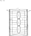
- Each consolidation unit is assigned a processing area within the construction field, with the processing areas are preferably arranged symmetrically with respect to a center plane or center axis which is perpendicular to the construction field and which passes through a center point of the construction field (cf. Fig. 2 , 10a / 10b and 11b ).
- This configuration can particularly advantageously be combined with the above embodiment with several elongated oval impingement surfaces of partial flows of the gas flow within the construction field.
- a single impact surface according to the invention is sufficient for an improved removal of contaminants from the process chamber.
- a single impact surface according to the invention can be generated which has the same point as its center.
- the center point of the impact surface is arranged centrally between the individual processing areas or, if necessary, in the middle in the overlapping area of the individual processing areas (cf. Figure 10b and 11b analogous). Since the gas flow according to the invention is deflected away from the impingement surface on all sides after it hits the construction field, the process gas flowing over the construction field to the edge of the construction field flows through only one processing area in this arrangement.
- the gas flow carries contamination from one processing area directly to the edge of the construction field and not to another processing area, so that a multiplication of the number of solidification units does not lead to an increase in the amount of contamination above a processing area.
- This principle of a central arrangement of impact surfaces with respect to the processing areas can also be applied analogously to cases with several impact surfaces.
- a consolidation unit can in particular be a laser scanner unit or a scanner or a line exposure unit.
- Processing areas can be identical areas within the construction site, overlap one another or lie next to one another without overlapping.
- the processing areas together cover essentially the entire construction area, so that the entire construction area can be used for production.
- the processing areas can be axially symmetrical to one another within the construction field.
- they can be four-fold rotationally symmetrical with respect to an axis of symmetry through the center point of the construction field, which is perpendicular to the construction field.
- the gas supply device preferably comprises at least one fastening device for releasably fastening at least one nozzle for shaping the gas flow.
- the at least one nozzle is selected in advance from a larger number of nozzles that can be fastened by means of the fastening device and fastened by means of the fastening device, a flow direction and / or a flow profile of the gas flow in the process chamber being changed by selecting the at least one nozzle.
- This change in the direction of flow can affect the gas flow according to the invention as a whole, which causes a lateral displacement of its impingement surface within the construction field.
- the change can relate to a partial flow of the gas flow according to the invention, which leads to a change in the geometric shape and / or the size of the impact surface according to the invention leads.
- the gas supply device preferably comprises at least one switchable nozzle for shaping the gas flow, which can be switched between a non-functional state and a function for injecting the process gas and / or between at least two predefined configurations or states of a three-dimensional inlet geometry of the nozzle and / or one Opening cross-section and / or an orientation of a nozzle opening relative to the construction field and / or process chamber wall is switchable, with a suitable combination of at least two of the following parameters being selected and set: (i) inflow velocity of the gas flow into the process chamber, (ii) three-dimensional inlet geometry of the nozzle, (iii) opening cross-section of a nozzle opening and (iv) orientation of a nozzle opening relative to the construction field and / or process chamber wall.
- the method according to the invention just described for designing the gas supply device is carried out individually or in combination, preferably in an automated manner, preferably depending on at least one of the following criteria: (i) a geometry and / or size and / or arrangement of at least one area to be consolidated in a topmost layer of building material within the construction field, (ii) a position of a coater within the process chamber, (iii) a position of a movable gas supply unit and / or a movable gas discharge unit within the process chamber, (iv) a position of a movable guide surface for guiding process gas in at least one predefined direction within the process chamber, (v) selected properties of one in the construction process construction material used, e.g. B.
- the z. B. can be an error signal.
- a second aspect of the disclosure is a method for generating a ceiling gas flow during the generative production of a three-dimensional object in a process chamber by layer-by-layer application and selective solidification of a building material within a building field arranged in the process chamber.
- the process chamber has a chamber wall with a process chamber ceiling above the construction field.
- a ceiling gas flow of a process gas is passed through the process chamber at least temporarily before and / or during and / or after the production of the object, which flow from the process chamber ceiling in the direction of the construction field in a controlled manner.
- the ceiling gas flow is fed to the process chamber through several ceiling inlets formed in the process chamber ceiling, which are distributed over an area of the process chamber ceiling and which are designed and / or arranged and / or controlled in such a way that the ceiling gas flow when exiting the ceiling inlets is essentially perpendicular to the construction field pointing downwards towards the construction site.
- the aforementioned monitoring or control of the flow behavior of the ceiling gas flow is carried out by the properties of the ceiling inlets, which are initially described generally above and described in more detail below.
- the area of the process chamber ceiling over which the ceiling inlets are distributed can be a sub-area of the process chamber ceiling in terms of its extension or area or it can extend over the entire process chamber ceiling.
- “Essentially perpendicular” includes in particular angular ranges of at least 45 °, preferably at least 70 °, particularly preferably at least 80 °, with respect to the construction field.
- the ceiling gas flow can therefore effectively prevent the contamination that occurs when the construction material solidifies from spreading upwards towards the process chamber ceiling. In this way, an accumulation of soiling in the upper areas of the process chamber and in particular a deposition of soiling on a coupling window or other optical devices for radiation required for selective solidification can be prevented.
- the method according to the second aspect of the disclosure can particularly advantageously be combined with the method according to the first aspect of the invention described above.
- the ceiling gas flow can be combined with the gas flow described above with an elongated oval impingement surface within the construction field (hereinafter sometimes subsumed under the term "central gas flow") in the method according to the invention. Since these two gas flows of the process gas in the process chamber are essentially in the same direction - namely essentially vertically downwards towards the construction field - they do not interfere with one another in their flow path and thus also in their cleaning effect. In particular, due to the essentially same direction of the top and the central gas flow, there are hardly any process gas eddies that could interfere with the removal of contaminants.
- the combination of the two aspects results in an advantageous synergy effect because the ceiling gas flow and the central gas flow according to the invention mutually support one another in the removal of contaminants from the process chamber. While the central gas flow with its elongated oval impingement surface ensures effective removal of dirt directly above the construction field, all other volume areas of the process chamber with the ceiling gas flow can be largely kept free of contamination by the ceiling gas flow covering them down to the construction field and - with a suitable arrangement or multiple outlets - pushes there.
- the central gas flow according to the invention with the elongated oval impingement surface can also be regarded as a part of the ceiling gas flow. This can for example with regard to be the case for homogeneous and / or area-wide properties of the ceiling gas flow.
- the ceiling inlets are preferably designed and / or arranged and / or controlled in such a way that the ceiling gas flow is formed essentially homogeneously in a region of the process chamber.
- Said area comprises at least a lowermost tenth, preferably at least a lowermost fifth, particularly preferably at least a lowermost third of a height of the process chamber, which is measured in the vertical direction from the construction field to the process chamber ceiling, vertically above the construction field.
- the named area comprises at least the area of the building area in a plane of the building area and / or parallel above the building area, preferably additionally an area surrounding the building area, particularly preferably essentially an entire area of a process chamber floor.
- a lateral extent of space around the construction field e.g. B. understood within a distance of 5 cm around the construction field.
- the process chamber floor is used in the context of the invention as a construction field, i.e. H. concretely understood a construction base mentioned at the beginning or an upper construction material layer applied thereon, comprehensive structure.
- the process chamber floor lies below the process chamber ceiling. It is understood as a surface in one plane, essentially without a level difference between the construction field and a floor slab framing the construction field.
- the term "homogeneous" presupposes a two-dimensional expression of the ceiling gas flow without spaces in which a process gas volume essentially rests, or moves in a different or undefined manner. Furthermore, essentially the same speed is assumed in the case of an essentially flat ceiling gas flow. This results in a constant downward movement of the process gas that has flowed in in a defined spatial area of the process chamber.
- the homogeneity can be measured, for example, as an essentially uniform dynamic pressure at a certain height level in the process chamber above the construction field.
- the homogeneity of the ceiling gas flow can be influenced, for example, by a size and / or density of the distribution of the ceiling inlets in the process chamber ceiling and / or by uniform or uneven exposure of the ceiling inlets with the process gas. Further criteria are, for example, the number of ceiling inlets, a total opening cross-sectional area and cross-sectional shape (s) of the ceiling inlets.
- the process chamber preferably has a process chamber floor located below the process chamber ceiling and the construction field extends over a partial area of the process chamber floor. Furthermore, a distribution of opening cross-sectional areas of the ceiling inlets on the process chamber ceiling is essentially uniform relative to a total area of the process chamber floor, the ceiling inlets being designed and / or arranged and / or controlled in such a way that partial ceiling gas flows of the ceiling gas flow when exiting the ceiling inlets are each essentially perpendicular are directed downwards towards the construction field on the process chamber floor.
- the uniform distribution can be achieved, for example, in that the ceiling inlets are at least similarly spaced apart with the same design and / or opening cross-sectional area.
- the ceiling inlets are at least similarly spaced apart with the same design and / or opening cross-sectional area.
- a ratio of an opening area of the ceiling inlets to a process chamber floor area can always be between 1/10 and 1/30, on average 1/20, with a subdivision of the process chamber floor into 25 or 100 quadrants.
- the opening cross-sectional area can be calculated by means of an orthogonal projection of the openings of the ceiling inlets onto the process chamber floor in such a way that only part of the actual opening cross-sectional area is evaluated if the ceiling inlets are not completely oriented to the process chamber floor.
- Essentially perpendicular means that the cross-sections of individual partial flows of the ceiling gas flow can also be fanned out so that, for B. result in conical partial flows.
- the ceiling gas stream consisting of partial ceiling gas streams can flow essentially in a laminar manner from the process chamber ceiling in the direction of the process chamber floor.
- the blanket gas flow is preferably passed through the process chamber at least temporarily before and / or during and / or after the selective solidification of the building material, preferably essentially during the entire process of selective solidification.
- the ceiling gas flow is preferably also active between two solidification processes, e.g. B. in an operational pause in the solidification process to clean the process chamber atmosphere so that contamination such as smoke does not waft through the process chamber in an uncontrolled manner, but is reliably held in a lower area of the process chamber and / or is particularly preferably transported away through an outlet device.
- the process chamber ceiling comprises a cavity with a wall which is essentially closed in an outer wall area facing away from the process chamber and has ceiling inlets in an inner wall area adjoining the process chamber.
- the cavity serves as an intermediate zone between one or more supply lines into the cavity and the ceiling inlets, which lead a process gas volume from the cavity into the process chamber.
- the cavity is preferably designed in such a way, in particular with regard to a suitable height in the direction perpendicular to the construction field, that a process gas volume flowing in through the supply line (s) initially spreads in the cavity instead of directly through nearby ceiling inlets Flow towards the process chamber.
- the inner wall surface can have baffles opposite openings in the supply line (s) towards the cavity, which deflects an incoming process gas jet, preferably on all sides, into the cavity.
- the homogeneity of the ceiling gas flow can be considerably improved by partial flows of the gas flow flowing into the process chamber from the ceiling inlets at essentially the same speed.
- the cavity can also calm down the process gas introduced in that its speed is significantly slowed after it has escaped from the supply line (s) before it flows into the process chamber.
- the inner wall area can in principle take up any proportion of the area of the process chamber ceiling. It is preferably as large a proportion as possible with the advantage of a better flatness and thus homogeneity of the ceiling gas flow.
- the fact that the outer wall area is “essentially closed” means in particular that structural facilities such as supply lines are an exception.
- the inner wall area is essentially formed by a plate, preferably a perforated plate.
- the ceiling inlets are at least partially formed by holes in the plate or the perforated plate.
- the plate or the perforated plate has at least 10 holes, preferably at least 100 holes, particularly preferably at least 1000 holes.
- an average opening cross-sectional area of the holes is at most 10 cm 2 , preferably at most 2 cm 2 , in particular preferably at most 0.1 cm 2 .
- a total of the opening cross-sectional areas of the holes is at most 20% of a total area of a process chamber floor, preferably at most 10% of a total area of the process chamber floor, particularly preferably at most 5% of a total area of the process chamber floor.
- the perforated plate can for example be a stamped or perforated sheet metal or a porous plate made of any material.
- the perforated plate can also represent, for example, one or more fine-meshed wire grids, e.g. B. a filter mat.
- a cassette with channels of a suitable length can be used for this purpose, the alignment of which is essentially identical to the direction of flow of the ceiling gas flow, essentially perpendicular to the construction field.
- Such channels have the advantage of improving the distribution and shape of the ceiling gas flow by guiding the individual ceiling gas partial flows and additionally reducing turbulence.
- At least one ceiling inlet and / or at least one additional gas inlet into the process chamber is designed and / or is controlled in such a way that, depending on a spatial design of the process chamber and / or on a position and / or size of a a speed and / or an alignment and / or a jet cross section of a ceiling partial gas flow flowing out of the ceiling inlet or the additional gas inlet can be varied before and / or during and / or after the production of the object.
- the additional gas inlet can be, for example, an inlet of a central gas flow according to the above first aspect of the invention.
- This configuration enables a targeted control of inlets such. B. nozzles to create deliberately inhomogeneous zones within the process chamber.
- Such specifically generated inhomogeneities of the ceiling inflow can, for. B. be advantageous with specific process chamber geometries, for example with a rugged or curved design of the process chamber wall, or with variable flow guidance within the process chamber, such as. B. by adjustable guide surfaces.
- a selective higher speed of certain partial ceiling gas flows or a targeted and controlled generation of eddies can make the freeing and keeping clear of corners, niches, etc. in the process chamber, which would otherwise be insufficiently flushed by the process gas, of contamination.
- the process chamber ceiling has at least one coupling window for coupling in one for solidifying the building material serving radiation in the process chamber.
- the ceiling inlets are distributed essentially uniformly over an entire area of the process chamber ceiling, with the exception of an area occupied by the at least one coupling window.
- a recess in the process chamber ceiling can also have, for example, a camera or other sensors for process monitoring.
- the process chamber ceiling and / or the inner wall area has / have at least one central inlet in a section adjoining the at least one coupling window, which is designed and / or controlled in such a way that a central partial ceiling gas flow flows out from it to the construction field during operation and is preferably expanded in such a way that the central partial ceiling gas flow based on a process chamber height between the construction field and the at least one coupling window located vertically above it is at least one tenth, preferably at least one fifth, particularly preferably at least one third of the process chamber at its edges converges or overlaps with adjacent ceiling partial gas flows.
- an essentially full-area gas flow is created at least over the entire construction field and preferably additionally in the vicinity of the construction field, which flows in a controlled manner towards the construction field.
- the speed of the ceiling gas flow does not have to be homogeneous in the sense of the above definition.
- the central partial ceiling gas flow can be used here, for example have a higher velocity than the other ceiling partial gas flows.
- the expansion is understood here as being related to the cross section of the ceiling partial gas flow. It can be conical, for example, in order to direct the central partial ceiling gas flow into areas of the process chamber in which a process gas volume would otherwise essentially rest or move in an undefined manner because it is not directly acted upon by a ceiling gas flow flowing out of the cavity. In particular, this can be the case for areas lying below a coupling window.
- a widening preferably takes place here to such an extent that the contours of projections, specifically not orthogonal projections, of three-dimensional inner walls of the central inlet and the immediately adjacent ceiling inlets on the building site approach, touch or overlap, whereby at least one tenth, preferably an essentially homogeneous ceiling gas flow is formed at least in a bottom fifth, particularly preferably at least in a bottom third of a process chamber height.
- a plurality of such central inlets are particularly preferably arranged around the coupling window (s) in order to achieve an equalization of the ceiling gas flow.
- the inlet nozzles can also be designed in such a way that partial ceiling gas flows that are asymmetrical in cross section are generated.
- the process gas is supplied to the process chamber in a preferably closed process gas circuit and discharged therefrom through an outlet.
- the ceiling gas flow represents at least a part of the process gas cycle.
- Inlet and / or discharge lines of the process gas cycle also include a delivery unit, by means of which a speed and / or speed distribution and / or pressure distribution of an overall process gas flow or the ceiling gas flow in the process chamber before and / or during and / or is changed after the object is manufactured.
- the supply / discharge can take place continuously, steadily, dynamically, at regular and / or irregular intervals, etc.
- the delivery unit can, for example, comprise a switchable pump, turbine or pump turbine and / or also a propeller.
- the process gas distribution in the process chamber and / or the removal of contaminants from it can be controlled and thus, for example, based on specific properties of the process chamber and the object to be produced in a specific application and / or specific Process phases can be adjusted. In this way, the process gas throughput of the overall process gas flow or of the ceiling gas flow in the process chamber can be increased, in particular in process phases with increased pollution.
- An impact surface of the central gas flow within the construction field can have any shape.
- the shape of the impact surface can be circular, for example.
- its essentially elongated oval impingement surface can be regular to elliptical or else irregular.
- the shape of the impact surface can also be variable during operation, e.g. B. when a coater to apply a layer of building material moves over the construction field and thereby deflects the central gas flow for a certain period of time or makes it unstable. They can interact be designed or selected with a training, arrangement and / or control of one or more outlets.
- the central area within the construction field can, for example, not take up more than about 60%, preferably not more than about 20%, particularly preferably not more than about 10% of a total area of the construction field .
- a preferably adjustable volume ratio of the ceiling gas flow to the central gas flow and / or to the side gas flow in the process gas circuit is at least 1: 1, preferably at least 2: 1, particularly preferably at least 3: 1, and / or at most 7: 1, preferably at most 6: 1, particularly preferably at most 5: 1.
- a volume ratio for example, a specific construction field size and / or process chamber height from the construction field to the process chamber ceiling can be taken into account in an application.
- a ratio of a total inlet opening area to a total outlet opening area of the process gas circuit is varied before and / or during and / or after the production of the object.
- a speed and / or a pressure of the process gas are / is changed at least in a partial area of the process chamber.
- the speed of the process gas circulation in the process gas circuit can advantageously be varied or adapted.
- the selective consolidation is preferably carried out by means of a consolidation device which comprises at least two consolidation units.
- Each consolidation unit is assigned a processing area within the construction field.
- the processing areas are preferably arranged symmetrically with respect to a central plane or central axis which is perpendicular to the construction field and which passes through a center point of the construction field.
- Another aspect of the invention is a control unit for a device for the generative production of a three-dimensional object, the control unit being designed to generate control commands for preferably automated implementation of a method according to the first aspect of the invention and / or the second aspect of the disclosure.
- Yet another aspect of the invention is a device for the generative production of a three-dimensional object, which is designed and / or controlled for a preferably automated implementation of a method according to the first aspect of the invention and / or the second aspect of the disclosure.
- the control can take place, for example, by means of the control unit according to the invention.
- the manufacturing device according to the invention comprises a process chamber for manufacturing the object by applying and selectively solidifying a building material in layers within a building area arranged in the process chamber.
- the device comprises a gas supply device for supplying a process gas to the Process chamber during the manufacture of the object and an outlet for discharging the process gas from the process chamber.
- the gas supply device is designed and / or is arranged relative to the construction field and / or is controlled in such a way that a gas flow of the process gas flowing through the process chamber is shaped in such a way that at least one essentially elongated oval impingement surface of the gas flow is generated within the construction field .
- the process chamber of the device has a chamber wall with a process chamber ceiling above the construction area.
- several ceiling inlets for supplying a ceiling gas flow to the process chamber are formed, which are distributed over an area of the process chamber ceiling and which are designed and / or arranged and / or controlled in such a way that the ceiling gas flow when exiting the ceiling inlets essentially vertically downwards is directed towards the construction site.
- a device 1 for the generative production of a three-dimensional object is described, which is preferably automated Implementation of a manufacturing method according to the invention is designed and / or controlled.
- the layer construction device 1 shown schematically is a laser sintering or laser melting device.
- a carrier 7 which is movable in a vertical direction V and to which a base plate 8 is attached which closes the container 5 at the bottom and thus forms its bottom.
- the base plate 8 can be a plate formed separately from the carrier 7 and attached to the carrier 7, or it can be formed integrally with the carrier 7.
- a platform 9 can also be attached to the base plate 8 as a construction base on which the object 2 is constructed.
- the object 2 can, however, also be built on the base plate 8 itself, which then serves as a construction base.
- Fig. 1 the object 2 to be formed in the container 5 on the platform 9 below a construction field 10 defined by the upper edge of the container wall 6 is shown in an intermediate state with several already solidified layers, surrounded by the building material 11 that has remained unsolidified.
- the laser sintering device 1 further contains a storage container 12 for a build-up material 13 which can be solidified by electromagnetic radiation, in this example powder-form, and a coater 14, which can be moved in a horizontal direction H, for applying the build-up material 13 in layers Construction base or on a layer applied last within the construction field 10.
- a radiant heater 15 for heating the applied construction material 13 is arranged in the process chamber 3.
- An infrared radiator, for example, can serve as the radiant heater 15.
- the laser sintering device 1 contains a consolidation device 30 (hereinafter also called exposure device) with a laser 31 which generates a laser beam 32.
- the laser beam 32 is deflected via a deflection device 33 and focused by a focusing device 34 via a coupling window 35, which is attached in the process chamber ceiling 4a, onto the construction base or a layer of construction material 13 that was applied last.
- the consolidation device 30 can in principle also have additional ones, in the side section in Fig. 1 Including non-visible consolidation units with further lasers and / or deflection and focusing devices and / or coupling windows.
- the laser sintering device 1 also contains a control unit 39, via which the individual components of the device are controlled in a coordinated manner for carrying out the construction process, in particular a method according to the invention (in Fig. 1 indicated by arrows).
- a control unit can also be attached partially or entirely outside the device 1.
- the control unit can contain a CPU, the operation of which is controlled by a computer program (software).
- the computer program can be stored separately from the device on a storage medium, from which it can be transferred to the device, in particular to the control unit 39, can be loaded.
- the control unit is preferably a control unit according to the invention.
- the construction base which in this example is a surface of the platform 9, is at the start of the manufacturing process at the height of the construction field 10 and is lowered by a height corresponding to the desired layer thickness to apply a layer of construction material.
- a layer of the powdery construction material 13 is applied to the construction base or an already existing upper powder layer.
- the application takes place at least over the entire respective cross section of the object 2 to be produced.
- the powdery building material 13 is heated to a working temperature by means of the radiant heater 15.
- the cross section of the object 2 to be produced is then scanned by the laser beam 32, so that the powdery building material 13 is solidified at the points that correspond to the cross section of the object 2. These steps are repeated until object 2 is completed.
- a gas flow 40 of a process gas is supplied to the process chamber 3 by a gas supply device (not shown) arranged in the process chamber ceiling 4a during the manufacture of the object 2 in order to remove any contamination from the process chamber 3 during the selective solidification.
- An inlet of the gas supply device on the process chamber side can have any suitable arrangement in the process chamber ceiling 4a and configuration.
- the gas flow 40 leaves the process chamber 3 through outlets 42a and 42b arranged on opposite construction field sides approximately at construction field height.
- the outlets 42a and 42b are in Fig. 1 purely schematic indicated. They can have any suitable arrangement and geometry, in particular according to the advantageous embodiments of the invention set out above.
- the outlets 42a and 42b can be arranged in or on the chamber wall 4, directly on the edge of the construction field or at a distance therefrom, and not necessarily at the height of the construction field.
- the gas flow 40 flows through the process chamber 3 unguided and essentially vertically, that is, apart from a possible billowing of the gas flow 40 and a slight deviation of edge regions of the gas flow 40 by up to about 20 ° from a perpendicular with respect to the construction site 10 , towards construction site 10.
- the gas flow 40 hits the upper layer of building material in an impact area A3 according to the invention located centrally within the construction site 10 and is deflected laterally by this layer and partly by suction from the outlets 42a and 42b.
- the gas stream then flows away, preferably essentially parallel to the construction field 10, in the direction of the outlets 42a and 42b and in the process transports contaminants out of the process chamber 3.
- Fig. 2 shows a further embodiment of the manufacturing device 1 according to the invention. It differs from the device Fig. 1 in the configuration of the solidification device 30 and a specific configuration of an inlet of the gas supply device on the process chamber side.
- the manufacturing device 1 in Fig. 2 is a so-called multi-scanner machine, because the consolidation device 30 comprises several consolidation units. In the side cut of the Fig. 2 you can see two of them. Components of a consolidation unit 30a on the left in the figure are labeled with additional index "a", those of the other consolidation unit 30b on the right in the figure with additional index "b".
- Each consolidation unit comprises, purely by way of example, a laser 31a / 31b which generates a laser beam 32a / 32b, as well as a deflection device 33a / 33b, a focusing device 34a / 34b and a coupling window 35a / 35b.
- a consolidation unit can also comprise only one or some of the elements mentioned.
- Each consolidation unit is a processing area (in Fig. 2 left and right), which can be scanned by the respective laser beam 32a or 32b.
- the processing areas are arranged axially symmetrically with respect to a center plane that extends through a construction site center point Z0 and is perpendicular to construction site 10 and the plane of the drawing.
- the device 1 can further, in the side section Fig. 2 have invisible pairs of consolidation units, which are preferably similar to in Fig. 2 are arranged and / or formed.
- An example of a four scanner machine with a total of four consolidation units is given below with reference to FIG Figures 10a and 10b described.
- Figure 11a and 11b an example of a six-scanner machine with a total of six consolidation units is described.
- the gas supply device (not shown) in an inlet 43 on the process chamber side, which can be a nozzle, for example.
- the nozzle 43 does not protrude significantly from the process chamber ceiling 4a, here purely by way of example by about 4 cm down into the process chamber 3 at about 49 cm process chamber height, which is perpendicular from the construction area 10 to a coupling window 35a / 35b is measured.
- the inlet 43 can also protrude deeper or not at all into the process chamber 3.
- nozzle 43 is arranged approximately in the middle between the coupling windows 35a and 35b of the two solidification units 30a and 30b shown. Since the gas flow 40 flows essentially vertically downwards to the construction field 10, the impingement surface A3 of the gas flow 40 is also in the center of the construction field and thus in both processing areas within the construction field 10 that can be scanned by the two laser beams 32a or 32b. Thus, each processing area has its own Gas flow portion flows over that in Fig. 2 flows either to the left or to the right from the construction site center Z0. Any soiling that arises in the respective processing area is therefore transported away to the edge of the construction site by the respective gas flow components. The two lasers 31a and 31b consequently do not interfere with one another with regard to the contamination that they cause in the manufacturing process by irradiating the powder.
- Fig. 7 shows a schematic plan view of an example of the arrangement of the construction field in the process chamber of a manufacturing device according to the invention with streamlines of the gas flow above the Construction field. It can in particular the device 1 from Fig. 1 or 2 his.
- the construction field 10 has a rectangular construction field edge BR, which can preferably be square and can for example be 400 mm ⁇ 400 mm.
- the chamber wall 4 of the process chamber 3 is also rectangular here in a horizontal cross section at the height of the construction area. The axes of symmetry of the two rectangles coincide purely by way of example.
- a process chamber floor 4b lying approximately at the height of the construction field can be seen around the construction field 10.
- the elongated oval impingement surface A3 of the gas flow according to the invention is arranged symmetrically around a center point ZO of the construction field 10.
- it is elliptical, with a long axis of the ellipse parallel to a narrow side of the construction field B.
- the dashed line shows an orthogonal projection of the process chamber-side opening of an inlet of the gas supply line (for example the nozzle 43 in Fig. 1 or 2 ).
- the impact area A3 is larger than the opening projection of the inlet onto the construction field 10.
- the gas stream flows along the construction field 10 and the process chamber floor 4b to the outlets 42a and 42b, which, purely by way of example, extend over the entire respective narrow side of the chamber wall 4 parallel to the narrow sides of the construction field.
- the outlets 42a and 42b extend here at their two ends beyond the respective construction site side.
- any suction effect through the outlet on the gas flow volume above the construction field 10 is relatively small. Therefore, the deflection of the gas flow after impingement takes place mainly through the ricocheting of the gas flow on the upper layer of building material within the impact area A3 and through a subsequent flow of the gas flow components into the respective nearby areas which are not acted upon by the gas flow continuously flowing in at least during solidification.
- the streamlines of the gas stream components flowing off after the deflection to the outlets 42a, 42b are indicated by solid curved lines.
- Additional outlets can be provided on the longitudinal sides of the chamber wall 4, in particular in the center, in order to support the removal of the gas flow components flowing off the "narrow sides" of the ellipse A3 from the process chamber.
- FIG. 3 is a schematic side sectional illustration of an example of streamlines of a gas flow according to the invention in the process chamber which is part of the production device 1 from FIG Figure 1 or 2 can be.
- the gas stream 40 flows into the process chamber 3 through the inlet 43, which z. B. can be designed as a nozzle.
- the inlet 43 which z. B. can be designed as a nozzle.
- the statements relating to Fig. 7 or 9a be valid.
- the nozzle 43 has an inner cross-sectional length Li which increases in the direction perpendicular to the construction field 10 (which is in the image plane of FIG Fig. 8 lies). As a result, the gas stream 40 becomes wider when it passes through the nozzle 43 in the direction of this internal cross-sectional length or it is fanned out.
- an inner cross-sectional area of the nozzle 43 preferably remains essentially constant over the extent of the nozzle 43 in the direction of the construction field 10, so that the speed of the gas flow 40 also remains essentially unchanged when passing through the nozzle 43.
- the fanning effect of the nozzle 43 gives way to the image plane Fig. 8 an outer gas flow line of the gas flow 40 it is indicated by a solid line - for example by about 20 ° from a perpendicular (90 °) with respect to the construction field 10.
- the perpendicular corresponds approximately to the direction of a central gas flow line, likewise indicated by a solid line, which flows to the center point ZO of the construction field 10.
- the course of the gas flow lines in the edge regions of the gas flow 40 can become flatter (in Fig. 8 indicated by a dashed line).
- FIGS 9a-9d some examples of an inlet of the gas supply device in the form of a nozzle with a fanning effect on the gas flow according to the invention are shown below.
- the gas supply line (not shown) opening into the nozzle always has a circular internal cross section, purely by way of example.
- the nozzle preferably also has here, as in FIG Fig. 8 , a substantially constant internal cross-sectional area for the gas stream flowing through the nozzle.
- nozzles shown can in particular in the with reference to Fig. 1-8 described manufacturing device 1 are used.
- Figure 9a shows a schematic plan view of a first embodiment of such a nozzle, for example the nozzle 43 from Fig. 2 or 8th can be.
- a circular line-side inner cross section 50 of the nozzle is shown in dashed lines.
- An inner cross section 60 on the process chamber side (here at the same time the opening area) of the nozzle has in this embodiment the shape of an ellipse which is concentric with the gas supply line.
- the opening surface 60 does not necessarily have to be elliptical; rather, it can be any desired elongated oval with two perpendicular axes of symmetry 61 and 62 shown.
- Figure 9b shows a schematic plan view of a second embodiment of the nozzle extending therefrom Figure 9a only differs in that the short axis of the ellipse is shifted parallel to the left by a distance d1 from a vertically drawn axis of symmetry of the circular inner cross section 50.
- the long axis a of the ellipse falls in the plan view of Figure 9b furthermore together with a horizontally drawn axis of symmetry of the circular inner cross section 50.
- Such an offset d1 can be used for a preferably slight deflection of the gas flow on its way through the nozzle in order to bring about a corresponding shift of its impact surface within the construction field.
- the offset d1 can be approximately 3 mm with an approximately 75 mm long axis a of the ellipse. Deviations from a concentric arrangement of the two inner cross-sections 50 and 60 are preferred low in order to avoid unfavorable turbulence in the gas stream flowing out of the nozzle in any case.
- Figures 9c and 9d show a third embodiment of an inlet of the gas supply device in the form of a nozzle 43 with a partially fanning effect on the gas flow according to the invention.
- This nozzle is different from the one Figure 9b in that its process chamber-side opening surface 60 extends in the direction of its longitudinal axis 61 considerably further to one side than to the opposite side with respect to a central axis 55 of the circular gas supply line.
- the shaping of the gas flow according to the invention can be adapted to special, for example asymmetrical, spatial conditions in the process chamber.
- the process chamber-side opening surface 60 of the nozzle can also be designed to be as asymmetrical as desired along its longitudinal axis 61, while Figures 9c-9d show an elliptical opening area 60 purely by way of example. Incidentally, this can be done here in relation to Figures 9a and 9b Executed apply accordingly.
- Figure 9c shows schematically two side views of the nozzle 43 rotated by 90 ° about the central axis 55 of the supply line relative to one another.
- the left side view is, as in FIG Fig. 8 , aligned with an inner cross-sectional length Li of the nozzle 43, which increases in the direction perpendicular to the construction field 10 (not shown).
- the gas flow 40 according to the invention (not shown) is fanned out as it passes the nozzle 43 in the direction of the increasing internal cross-sectional length Li.
- the right side view shows a tapering of the nozzle 43 in a direction perpendicular thereto with a constant internal cross-sectional area, whereby the gas flow 40 is bundled. Overall, this results in an elongated oval opening area on the process chamber side 60 of the nozzle 43, which leads to an elongated oval impingement surface of the gas flow 40 according to the invention within the construction field 10 (for example as in Fig. 7 illustrated).
- Figure 9d on the left a schematic top view of the nozzle from the process chamber side Figure 9c and on the right their schematic perspective view.
- the nozzle 43 has in FIG Figures 9c and 9d at its end with the circular internal cross section 50 an external thread 56 which represents the fastening device according to the invention.
- the process chamber ceiling 4a (not shown) has a complementary internal thread in this example.
- the opening surface on the process chamber side is not elliptical, but only axially symmetrical with respect to its longitudinal extent, but otherwise irregularly oval.
- a nozzle thus has only one axis of symmetry (its longitudinal axis) and, moreover, is not concentric with the gas supply line opening into the nozzle.
- FIG 10a shows a schematic side section of a process chamber of a manufacturing device according to the invention with four consolidation units, of which only two can be seen in the side section.
- a device 1 can be used Fig. 2 his.
- each consolidation unit 30a and 30b comprises a laser and focusing optics that generate a laser beam 32a / 32b that can scan an associated processing area 10a / 10b of a construction field 10.
- Figure 10b shows a (purely exemplary) square construction field Figure 10a in schematic plan view.
- four processing areas 10a, 10b, 10c and 10d of the four consolidation units are identical quadrants that completely cover the construction field 10. They overlap each other on facing sides. The areas of overlap are shown hatched. One side of the machining area 10c is shown for clarity.
- An elongated oval impingement surface according to the invention can here, for example, as in FIG Figure 11b be arranged in relation to processing areas 10a-10d.
- Figure 11a shows schematically in a top view an example of a construction area extension in a manufacturing device according to the invention by lining up three elongated oval impact surfaces of the gas flow according to the invention. Incidentally, in this example, this can be done above in relation to Figure 1-10 Executed apply.
- three impingement surfaces A3 are formed identically here (elliptical, for example as in FIG Fig. 7 ) and equally oriented. They also share a common axis of symmetry (not shown), each of which is the long axis of the ellipse. In addition, this common axis of symmetry also coincides with the long axis of symmetry of the rectangular construction field 10.
- the impact surfaces A3 intersect on mutually facing narrow sides of the ellipses. Overall, this results in an almost uniform flow course of the impinging gas stream according to the invention along the construction field 10, the gas stream after impingement predominantly over a short, almost straight distance from the impingement surface to the respective outlet 42a or 42b drains. Incidentally, this applies here in relation to Fig. 7 Executed accordingly.
- Figure 11b shows a schematic plan view of a further example of a building field extension in a manufacturing device according to the invention.
- Figure 11a only two elongated oval impact surfaces of the gas flow are lined up here.
- the same applies to this example in relation to FIG Figure 11a Executed accordingly.
- the construction field 10 is divided into six partially overlapping processing areas 10a-10f of six consolidation units of the consolidation device.
- the above applies here in relation to a four-scanner machine based on the Figures 10a / 10b Executed accordingly.
- the processing areas 10a-10f are also identical to one another here, and they are each preferably square.
- the processing area 10a is highlighted by hatching for clarity.
- the common axis of symmetry of the two impact surfaces A3 runs in Figure 11b essentially centrally through the construction field 10.
- This common axis of symmetry runs centrally and symmetrically with respect to the row of processing areas 10a, 10d and 10e arranged on the left in the figure and the row of machining areas 10b, 10c and 10f arranged on the right.
- a central symmetrical arrangement of the impact surfaces with respect to the processing areas 10a-10f has, among other things, the advantage of short, almost straight stretches for the gas flow flowing off to the outlets 42a / 42b after it has hit.
- the individual processing areas each have their own different gas flow components overflows, so that contamination via one of the processing areas does not or hardly reaches the other processing areas, so that the increased number of solidification units does not have a negative effect on the removal of contamination above the construction field.
- the volume ratio of the ceiling gas flow to the central gas flow can be, for example, 5: 1.
- the resulting six parts by volume of the process gas can then be discharged from the process chamber, for example, through three outlets each arranged on the two longitudinal sides of the construction field (in particular each on a processing area).
- Figure 12a Figure 3 is a schematic side sectional view of the process chamber of a manufacturing device with a ceiling gas flow.
- the manufacturing device can in particular with reference to Fig. 1-11 be described laser sintering device 1.
- a ceiling gas flow 44 is supplied to the process chamber 3 through ceiling inlets 45 (indicated by solid arrows) arranged in a process chamber ceiling 4a (indicated by dashed arrows).
- a beam path of a consolidation device that has one or more, for example four, consolidation units, each with one May include laser is indicated schematically by two legs of a triangle 32 running through the process chamber 3.
- FIG. 13 is a schematic top view of the construction field 10 and of the ceiling inlets 45 in the manufacturing device from FIG Figure 12a .
- the ceiling inlets 45 for generating a substantially homogeneous ceiling gas flow 44 are distributed substantially uniformly over an entire area of the process chamber ceiling 4a, with the exception of an area occupied by coupling optics (for example coupling window, not shown) for the solidification radiation.
- Fig. 13 is a schematic lateral sectional view of a manufacturing device according to the invention, in which a central gas flow is combined with a ceiling gas flow in a closed process gas circuit.
- the manufacturing device can for example with reference to Figure 1-12 Have the properties shown, the process chamber 3 can in particular be similar to that of Figures 12a / 12b be designed.
- Supply lines 46a and discharge lines 46b of the process gas circuit comprise a delivery unit 47, which in this example combines a turbine and additionally a filter in a circulating air filter device.
- the filter serves to remove contaminants from the process gas discharged from the process chamber 3.
- a process gas supplied to the process chamber 3 via ceiling inlets 45 is divided into a ceiling gas flow 44 and a central gas flow 40 (for example according to the first aspect of the invention).
- This division is made depending on the requirements of the specific application using various feeder branches arranged measuring points 51 monitored and / or regulated.
- the measuring points can, for example, record the respective process gas flow.
- the regulation can take place, for example, as a function of the structural design of the process chamber 3 and / or of a specific manufacturing process.
- Fig. 14 is a schematic side sectional view of a manufacturing device in which a side gas flow is combined with a ceiling gas flow in a closed process gas circuit.
- the device in Fig. 14 differs from that one Fig. 13 only in that instead of the central gas flow 40, a side gas flow 49 is fed to the process chamber 3.
- the side gas flow 49 flows essentially parallel and preferably laminar over the construction field 10. It is fed to the process chamber 3 via a side inlet of the supply line 46a arranged on one construction field side and discharged from the process chamber via an outlet of the discharge line 46b arranged on an opposite construction field side.
- Fig. 15 is a schematic perspective view of a perforated plate for generating a ceiling gas flow in a process chamber, the ceiling of which has a cavity for this purpose (not shown).
- the perforated plate 52 is in FIG Fig. 15 an example of an inner wall area of such a cavity.
- the perforated plate 52 has a plurality of holes 53 which represent ceiling inlets.
- the perforated plate 52 also has a larger inner opening 54 in its central area, which, when the perforated plate 52 is installed in the process chamber ceiling 4a, surrounds, inter alia, coupling windows 35a, 35b for coupling the solidification radiation into the process chamber 3.
- the perforated plate 52 has a total of about 2000 holes 53, which essentially extend over the perforated plate 52 - in particular with the exception of the inner opening 54 and two approximately hexagonal surfaces 71, which serve as baffles for deflecting gas flows which enter the cavity, not shown the process chamber ceiling 4a, and thus ensure the same or approximately the same speed of the partial flows of the ceiling gas flow - are evenly distributed because they are of the same size and are arranged on average at regular intervals.
- the holes 53 here have a diameter of approximately 2.5 mm.
- the ratio of an area perforated by holes 53 to an entire process chamber ceiling area is approximately 3.8%.
- Figure 16 shows the perforated plate 52 from Fig. 15 in an installed state in the ceiling 4a of a process chamber 3 in a schematic perspective view obliquely from below.
- four coupling windows 35a, 35b, 35c and 35d of a four-scanner machine which in particular have a device as in FIG Fig. 2 can be arranged in the process chamber ceiling 4a.
- a nozzle 43 through which the central gas flow 40 according to the invention (not shown) can flow into the process chamber 3 is arranged in the middle between the coupling windows 35a, 35b, 35c and 35d.
- Figure 17 shows a process chamber 3, partly in a vertical cross section, in a schematic perspective view obliquely from above, with a perforated plate 52 built into its ceiling 4a, as in FIG Figures 15 and 16 .
- it can be a process chamber 3 of the in Fig. 2 act shown four-scanner machine 1.
- a gas supply line or supply line 46a opens into a central gas inlet, here in the form a nozzle 43, which represents the gas supply device according to the invention according to the first aspect of the invention.
- the process chamber ceiling 4a lies above a construction field 10 and comprises a cavity 73 with a wall.
- This cavity wall comprises an outer wall area 74 facing away from the process chamber 3 and an inner wall area adjoining the process chamber 3, which is formed by the perforated plate or the perforated plate 52.
- an outlet 42a or 42b which has two horizontally extending opening slits, attaches directly above the process chamber floor 4b or a plane of the construction field 10.
- the outlet 42a or 42b extends at a distance from an edge of the construction field 10 and parallel to one side of the construction field 10 and, in this exemplary embodiment, extends its length beyond the parallel side length of the construction field 10, so that dirt can be transported away in Areas above the process chamber floor 4b that are not above the construction field 10 is improved.
- Figures 15 to 17 show that a process chamber ceiling 4a does not necessarily have to be planar over its entire surface and / or must lie parallel to the construction field 10.
- the process chamber ceiling 4a shown here is essentially flat vertically above the construction field 10 and lies parallel to it, but has a section 72 rising obliquely away from the process chamber floor over a region of the construction field edge.
- This section 72 does not impair the functioning of the ceiling gas flow, but, like the entire inlet area of the process chamber ceiling 4a, is designed such that a homogeneous ceiling gas flow pours out of the openings 53 into the process chamber 3 essentially perpendicular to the construction field 10. This is made possible by a defined control of a process gas volume, which from the two supply lines in this example (in Fig.
- a gas volume introduced into the cavity 73 does not flow on the shortest path through holes 53 of the perforated plate 52 located close to the supply lines into the process chamber 3, but initially continuously floods the cavity 73, so that after a short start-up phase essentially in the entire cavity 73 or essentially at all openings 53 of the inner wall region 52 towards the process chamber 3, there is essentially the same pressure, ie an overpressure relative to the process chamber pressure.
- Such an overpressure can, for. B. in the present embodiment of a process chamber ceiling 4a with a high number of openings 53 of the same shape and the same opening area, a homogeneous ceiling gas flow through the openings 53 of the inner wall / perforated plate 52 of the process chamber ceiling 4a.
- the partial flows of the ceiling gas flow have essentially the same velocities and essentially the same volume flow.
- An influencing factor in a desired homogenization of the ceiling gas flow can be a hole size, i. H. be a surface and / or shape of an opening cross section of the holes 53 in the inner wall region 52.
- a characteristic of the ceiling gas flow can be changed specifically with structurally simple means. Partial flows of the ceiling gas flow, which from the described surface 72 of the process chamber ceiling 4a at an angle to the construction field 10, initially pass through the holes 53 at a correspondingly acute angle to the construction field 10, can be caused by further effects, e.g. B.
- suction effects of other areas of the ceiling gas flow or a deflection by an adjacent vertical area of the process chamber wall, on their way to the construction field 10 are gradually led back in an approximately perpendicular direction to the construction field 10, whereby in a lower area, z. B. a lower half of the process chamber 3, a ceiling gas flow directed essentially perpendicular to the construction field 10 is again produced.
- the present invention has been described with reference to a laser sintering or laser melting device, it is not limited to laser sintering or laser melting. It can be applied to any method for the generative production of a three-dimensional object by applying layer by layer and selectively solidifying a building material (preferably in powder form), regardless of the manner in which the building material is solidified.
- the selective solidification of the applied building material can take place by an energy supply of any suitable type. Alternatively or in addition, it can also be carried out, for example, by 3D printing, for example by applying an adhesive.
- energy can generally be supplied to the building material, for example by electromagnetic radiation or particle radiation.
- the radiation acts on the building material in the respective area of a layer to be solidified in such a way that it changes its state of aggregation, undergoes a phase transition or another structural change and is in solidified form after a subsequent cooling process.
- the building material is preferably a powder, wherein the radiation can in particular be laser radiation.
- the radiation acts on an area of the respective layer that is to be solidified in such a way that powder grains of the build-up material are partially or completely melted in this area by the energy introduced by the radiation and, after cooling, are present as solid bodies.
- a solidification device for selective solidification by supplying energy can, for example, one or more gas or solid-state lasers or any other type of laser such.
- any device with which energy can be applied selectively as radiation to a layer of the building material can be used for selective consolidation.
- a laser it is possible, for example, to use another light source, an electron beam or any other energy or radiation source that is suitable for solidifying the building material.
- selective solidification can also be used can be used with a mobile line imagesetter.
- HHS high-speed sintering
- construction material in particular plastics, metals, ceramics, each preferably in powder form, sand, filled or mixed powder.
Landscapes
- Engineering & Computer Science (AREA)
- Chemical & Material Sciences (AREA)
- Materials Engineering (AREA)
- Manufacturing & Machinery (AREA)
- Physics & Mathematics (AREA)
- Optics & Photonics (AREA)
- Mechanical Engineering (AREA)
- Automation & Control Theory (AREA)
- Plasma & Fusion (AREA)
- Laser Beam Processing (AREA)
Description
Die vorliegende Erfindung bezieht sich auf ein Verfahren zum generativen Herstellen eines dreidimensionalen Objekts in einer Prozesskammer einer generativen Herstellvorrichtung durch schichtweises Aufbringen und selektives Verfestigen eines Aufbaumaterials innerhalb eines in der Prozesskammer angeordneten Baufelds. Dabei wird während der Herstellung des Objekts ein Prozessgasstrom der Prozesskammer zugeführt, der durch die Prozesskammer strömt und danach aus der Prozesskammer abgeführt wird. Die Erfindung richtet sich auch auf eine Vorrichtung, die zu einer vorzugsweise automatisierten Durchführung eines derartigen Verfahrens ausgebildet ist und/oder angesteuert wird, sowie auf eine Steuereinheit, die zur Generierung entsprechender Steuerbefehle ausgebildet ist. Insbesondere bezieht sich die vorliegende Erfindung auf Verfahren und Vorrichtungen, bei denen das Aufbaumaterial in Pulverform vorliegt.The present invention relates to a method for the generative production of a three-dimensional object in a process chamber of a generative production device by applying and selectively solidifying a building material in layers within a construction field arranged in the process chamber. During the production of the object, a process gas flow is fed to the process chamber, which flows through the process chamber and is then discharged from the process chamber. The invention is also directed to a device which is designed and / or is controlled to carry out such a method, preferably in an automated manner, and to a control unit which is designed to generate corresponding control commands. In particular, the present invention relates to methods and devices in which the building material is in powder form.
Verfahren und Vorrichtungen zum generativen Herstellen dreidimensionaler Objekte sind auch unter dem Begriff "Additive Manufacturing" oder "generative Fertigung" bekannt. Typischerweise wird dabei ein Objekt innerhalb eines Baufelds Schicht für Schicht auf einer höhenverstellbaren Bauunterlage aufgebaut. Hierzu wird eine jeweilige Schicht eines Aufbaumaterials auf die Bauunterlage bzw. eine zuvor vorhandene Schicht aufgebracht und selektiv in einem Bereich verfestigt, der einem Querschnitt des herzustellenden Objekts entspricht. Diese Schritte finden in einer Prozesskammer der Herstellvorrichtung statt, die in einem Maschinengehäuse der Herstellvorrichtung angeordnet ist. Ein Beispiel eines solchen Verfahrens ist das "selektive Lasersintern oder Laserschmelzen", bei dem das selektive Verfestigen des Aufbaumaterials durch das Scannen der jeweiligen Schicht mit einem Laserstrahl bewirkt wird. Innerhalb der Prozesskammer bildet oft ein Herstellbehälter einen Begrenzungsrahmen für das Aufbaumaterial, indem er das Aufbaumaterial auf der höhenverstellbaren Bauunterlage seitlich begrenzt. Als Baufeld wird dabei in der Regel eine durch den oberen Rand des Herstellbehälters begrenzte Fläche verstanden. Die jeweils oberste Schicht des Aufbaumaterials kann in der Praxis oft auch über den Rand des so definierten Baufelds hinaus aufgebracht werden; das au-ßerhalb des Baufelds aufgebrachte Aufbaumaterial dient jedoch nicht der Objektherstellung und wird daher weder selektiv verfestigt noch anschließend mit der Bauunterlage zusammen abgesenkt.Methods and devices for the generative production of three-dimensional objects are also known under the term “additive manufacturing” or “generative production”. Typically an object is built up layer by layer on a height-adjustable construction base within a construction field. For this purpose, a respective layer of a construction material is applied to the construction base or a previously existing layer and selectively solidified in an area which corresponds to a cross section of the object to be produced. These steps take place in a process chamber of the manufacturing device, which is arranged in a machine housing of the manufacturing device. An example of such a method is "selective laser sintering or laser melting", in which the selective solidification of the building material is effected by scanning the respective layer with a laser beam. Within the process chamber, a manufacturing container often forms a delimitation frame for the construction material, in that it laterally delimits the construction material on the height-adjustable construction base. As a rule, a construction area is understood to be an area delimited by the upper edge of the manufacturing container. In practice, the topmost layer of the building material can often also be applied beyond the edge of the building area so defined; however, the construction material applied outside of the construction site does not serve to produce the object and is therefore neither selectively consolidated nor subsequently lowered together with the construction base.
Beim selektiven Verfestigen können je nach Art des verwendeten Aufbaumaterials, insbesondere beim Sintern oder Schmelzen von Kunststoff- oder Metallpulver, unerwünschte Verschmutzungen wie Spratzer, Rauche, Schmauche, Dämpfe und/oder Gase entstehen, die sich in die Prozesskammer hinein ausbreiten. Zusätzlich können bei Verwendung eines pulverförmigen Aufbaumaterials Verschmutzungen dadurch entstehen, dass Pulver oder Pulverstaub z. B. durch Unregelmäßigkeiten im Dosier- oder Beschichtungsprozess oder durch einen zu hohen lokalen Impuls eines Gasstroms auf eine Pulvermenge in der Prozesskammer aufgewirbelt werden. Verschmutzungen können den Fertigungsprozess negativ beeinflussen, beispielsweise indem sie den scannenden Laserstrahl absorbieren, streuen oder ablenken, sich auf einem Einkoppelfenster für den Laserstrahl niederschlagen oder sich auf einer Aufbaumaterialschicht ablagern, wodurch störende Einschlüsse bei der nachfolgenden Verfestigung entstehen oder das Aufbringen der nachfolgenden Schicht beeinträchtigt wird.With selective solidification, depending on the type of building material used, in particular when sintering or melting plastic or metal powder, undesired contamination such as splashes, smoke, smoke, vapors and / or gases can arise that spread into the process chamber. In addition, when using a powdery build-up material, soiling can arise from the fact that powder or powder dust z. B. by irregularities in the dosing or coating process or be whirled up by a too high local impulse of a gas flow onto a quantity of powder in the process chamber. Contamination can have a negative impact on the manufacturing process, for example by absorbing, scattering or deflecting the scanning laser beam, depositing itself on a coupling window for the laser beam or depositing itself on a layer of building material, which causes disruptive inclusions in the subsequent solidification or the application of the subsequent layer is impaired .
Um hohen Qualitäts- und Effizienzanforderungen an den Fertigungsprozess zu genügen, müssen solche Verschmutzungen daher möglichst schnell von der Prozessstelle, wo sie entstehen, abtransportiert werden. Dabei soll es insbesondere vermieden werden, dass die Verschmutzungen erneut und/oder an einer anderen Stelle in der Prozesskammer in einen Pfad der Verfestigungsstrahlung gelangen. Bei Mehr-Scanner-Systemen, in denen mehrere Verfestigungseinheiten wie Laser eingesetzt werden, besteht darüber hinaus die Gefahr, dass Verschmutzungen aus dem Bearbeitungsbereich eines Laserstrahls in den Pfad eines anderen Laserstrahls gelangen und dadurch dessen Prozess gestört wird. Außerdem erhöht sich mit der Anzahl der aktiven Laserstrahlen der Verschmutzungsahteil in der Prozesskammer, was wiederum einen verbesserten Abtransport der Verschmutzungen erforderlich macht.In order to meet high quality and efficiency requirements for the production process, such contamination must therefore be removed as quickly as possible from the process point where it occurs. In this case, it should in particular be avoided that the soiling gets into a path of the solidification radiation again and / or at another point in the process chamber. In multi-scanner systems in which several consolidation units such as lasers are used, there is also the risk that contamination from the processing area of one laser beam can get into the path of another laser beam, thereby disrupting its process. In addition, the number of active laser beams increases the number of contaminants in the process chamber, which in turn requires improved removal of the contaminants.
In
Der Anmelderin sind ferner generative Herstellvorrichtungen bekannt, bei denen zum Abtransportieren von Verschmutzungen aus der Prozesskammer ein Gasstrom erzeugt wird, der mit einer kreisrunden oder einer länglichen, annähernd rechteckigen Auftrefffläche senkrecht auf eine obere Schicht des Aufbaumaterials zentral auftrifft und dadurch seitlich abgelenkt wird.The applicant is also aware of generative manufacturing devices in which a gas flow is generated to remove contaminants from the process chamber, which strikes an upper layer of the building material centrally with a circular or an elongated, approximately rectangular impact surface and is thereby deflected laterally.
Auch bei solchen Gasstromgestaltungen ergeben sich in der Prozesskammer Problemzonen mit einem unzureichenden Abtransport von Verschmutzungen, wie in
- Eine kreisrunde Auftrefffläche A1 des Gasstroms im Baufeld 10 (
Fig. 3 ) führt typischerweise dazu, dass bei der nach dem Auftreffen erfolgenden Ausbreitung (durch Pfeile angedeutet) des Gasvolumens entlang desBaufelds 10 die Geschwindigkeit (durch die jeweilige Pfeillänge angedeutet) des Gasstroms schnell mit wachsendem Abstand R vom Baufeldzentrum Z0 sinkt und zwar aufgrund einer rasch (proportional zu R) wachsenden Fläche der mit Strichlinien markierten Ringe, in denen sich das Gasvolumen radial nach außen ausbreitet. Dieser Umstand ist links in der Figur nochmals verdeutlicht. Bei einer im Vergleich zur Baufeldgröße kleinen runden Auftrefffläche A1 reicht die rasch sinkende Geschwindigkeit (und Dichte) des Gasstroms daher nicht aus, - um Verschmutzungen wirksam über lange Distanzen bis zum Baufeldrand abzutransportieren. Wird eine Geschwindigkeit des in die Prozesskammer eingeblasenen Gasstroms derart erhöht, dass sich eine Abfuhr von Verschmutzungen über eine lange Distanz verbessert, kann es unmittelbar nach dem Auftreffen innerhalb des Baufelds zu hohen Geschwindigkeiten des Gasstroms kommen, die zu nachteiligen Verblasungen des Aufbaumaterials führen können.
- A circular impact area A1 of the gas flow in construction site 10 (
Fig. 3 ) typically leads to the fact that during the expansion (indicated by arrows) of the gas volume along theconstruction field 10 after the impact, the speed (indicated by the respective arrow length) of the gas flow decreases rapidly with increasing distance R from the construction field center Z 0 , namely due to a (proportional to R) increasing area of the rings marked with dashed lines, in which the gas volume expands radially outwards. This fact is illustrated again on the left in the figure. In the case of a small, round impact area A1 compared to the size of the building site, the rapidly decreasing speed (and density) of the gas flow is therefore not sufficient, - to effectively transport dirt over long distances to the edge of the construction site. If the speed of the gas flow blown into the process chamber is increased in such a way that the removal of contaminants over a long distance is improved, the gas flow can reach high speeds immediately after it hits the construction area, which can lead to disadvantageous blowing of the construction material.
Eine längliche, annähernd rechteckige oder aber streifenförmige Auftrefffläche A2 (
In
Die Aufgabe der vorliegenden Erfindung ist es daher, ein verbessertes Verfahren und eine verbesserte Vorrichtung der eingangs genannten Art bereitzustellen, mit denen die Wirksamkeit und Vollständigkeit des Abtransports störender, bei der selektiven Verfestigung des Aufbaumaterials entstehender Verschmutzungen aus der Prozesskammer deutlich erhöht werden kann. Insbesondere sollen dabei die aus dem Stand der Technik bekannten Problemzonen unzureichenden Abtransports von Verschmutzungen in der Prozesskammer verringert werden.The object of the present invention is therefore to provide an improved method and an improved device of the type mentioned above, with which the effectiveness and completeness of the removal of disruptive contaminants from the process chamber resulting from the selective solidification of the building material can be significantly increased. In particular, the problem areas known from the state of the art in which contamination is inadequately transported away in the process chamber should be reduced.
Diese Aufgabe wird gelöst durch ein Herstellungsverfahren nach Anspruch 1, eine Steuereinheit nach Anspruch 14 und eine Herstellvorrichtung nach Anspruch 15. Weiterbildungen der Erfindung sind in den abhängigen Ansprüchen angegeben. Dabei können die Herstellvorrichtung und die Steuereinheit durch die untenstehenden und in den Ansprüchen angegebnen Merkmale des Verfahrens weitergebildet sein und umgekehrt. Merkmale verschiedener vorteilhafter Weiterbildungen und Ausführungsformen können ferner untereinander kombiniert werden.This object is achieved by a manufacturing method according to
Ein erster Aspekt der Erfindung ist ein Verfahren zum generativen Herstellen eines dreidimensionalen Objekts in einer Prozesskammer einer generativen Herstellvorrichtung durch schichtweises Aufbringen und selektives Verfestigen eines Aufbaumaterials innerhalb eines in der Prozesskammer angeordneten Baufelds. Dabei wird während der Herstellung des Objekts ein Prozessgas mittels einer Gaszufuhreinrichtung der Prozesskammer zugeführt und über einen Auslass aus der Prozesskammer abgeführt. Die erfindungsgemäße Gaszufuhreinrichtung ist so ausgebildet und/oder relativ zum Baufeld angeordnet und/oder wird so angesteuert, dass ein durch die Prozesskammer strömender Gasstrom des Prozessgases derart geformt wird, dass eine im Wesentlichen längliche ovale Auftrefffläche des Gasstroms innerhalb des Baufelds erzeugt wird.A first aspect of the invention is a method for the generative production of a three-dimensional object in a process chamber of a generative production device by applying and selectively solidifying a construction material in layers within a construction field arranged in the process chamber. During the production of the object, a process gas is supplied to the process chamber by means of a gas supply device and is discharged from the process chamber via an outlet. The gas supply device according to the invention is designed and / or arranged relative to the construction field and / or is controlled in such a way that a gas flow of the process gas flowing through the process chamber is shaped in such a way that an essentially elongated oval impingement surface of the gas flow is generated within the construction field.
Sowohl der Begriff "Gasstrom" als auch das Erzeugen der erfindungsgemäßen Auftrefffläche innerhalb des Baufelds setzen voraus, dass das den Gasstrom bildende Prozessgas mit einer Geschwindigkeit in die Prozesskammer einströmt, bei der ein Einlassbereich der Gaszufuhreinrichtung eine erfindungsgemäße strahlformende Wirkung hinreichend entfalten kann und der Gasstrom auch tatsächlich in der jeweiligen Richtung bis hin zum Baufeld in einer kontrollierten Weise strömen kann, wenn er auf seinem Weg durch die Prozesskammer nach Verlassen der Gaszufuhreinrichtung nicht weiter abgelenkt wird. Die genannte Kontrolle bzw. Steuerung des Strömungsverhaltens des erfindungsgemäßen Gasstroms erfolgt dabei durch die oben zunächst allgemein und nachfolgend ausführlicher beschriebenen formgebenden Eigenschaften der erfindungsgemäßen Gaszufuhreinrichtung.Both the term "gas flow" and the creation of the impact surface according to the invention within the construction field require that the process gas forming the gas flow flows into the process chamber at a speed at which an inlet area of the gas supply device can sufficiently develop a jet-shaping effect according to the invention and so can the gas flow can actually flow in a controlled manner in the respective direction up to the construction field when it is on its way through the process chamber after leaving the gas supply device is not distracted further. The above-mentioned monitoring or control of the flow behavior of the gas flow according to the invention takes place through the shaping properties of the gas supply device according to the invention, which are initially described generally above and described in more detail below.
Als "Auftrefffläche" wird daher im Rahmen der Erfindung diejenige Fläche innerhalb des Baufelds verstanden, die vom Gasstrom erreicht wird oder werden würde, wenn er in der Prozesskammer nach Verlassen der Gaszufuhreinrichtung bis zum Baufeld ohne weitere Ablenkung in einer kontrollierten Weise strömt oder strömen würde. In Fällen ohne weitere Ablenkung des Gasstroms nach Verlassen der Gaszufuhreinrichtung entspricht die Auftrefffläche daher demjenigen Bereich der obersten Aufbaumaterialschicht, in dem der Gasstrom auf die Schicht trifft und von dieser seitlich abgelenkt wird. Dabei kann eine Größe der Auftrefffläche beispielsweise in Abhängigkeit eines vom Gasstrom innerhalb des Baufelds erzeugten Staudrucks ermittelt werden, wie weiter unten im Detail beschrieben wird.In the context of the invention, the "impact area" is therefore that area within the construction field that is or would be reached by the gas flow if it flows or would flow in a controlled manner in the process chamber after leaving the gas supply device to the construction field without further deflection. In cases without further deflection of the gas flow after leaving the gas supply device, the impingement surface therefore corresponds to that region of the uppermost building material layer in which the gas flow strikes the layer and is laterally deflected by it. In this case, a size of the impact area can be determined, for example, as a function of a dynamic pressure generated by the gas flow within the construction field, as will be described in detail below.
Ein tatsächliches Auftreffen des Gasstroms auf dem Aufbaumaterial wird bei der Erfindung nicht zwingend vorausgesetzt. Vielmehr umfasst das erfindungsgemäße Verfahren auch Fälle, in denen der Gasstrom durch weitere Maßnahmen, beispielsweise eine Absaugung seitens des Auslasses, bereits vor Erreichen der obersten Aufbaumaterialschicht teilweise oder ganz seitlich abgelenkt wird. In solchen Fällen wird die erfindungsgemäße Auftrefffläche abstrakt gemäß der obigen Definition bestimmt, beispielsweise durch das Projizieren (im Allgemeinen keine Orthogonalprojektion) eines dreidimensional ausgebildeten, den Gasstrom formenden Einlassbereichs (nachfolgend kurz: Einlasses) der Gaszufuhreinrichtung auf das Baufeld. Zu möglichen Kriterien der erfindungsgemäßen Formung des Gasstroms und der daraus resultierenden Auftrefffläche zählen die Geometrie der prozesskammerseitigen Öffnungsfläche des Einlasses und ihre Orientierung relativ zum Baufeld, die Geometrie einer Innenwandung des Einlasses, beispielsweise relativ zu einem Leitungsquerschnitt des Prozessgas-Leitungssystems aufweitend oder aber verengend und daher bündelnd, insbesondere Abstand und Verhältnis eines Querschnitts der Prozessgas-Leitung und eines Querschnitts der prozesskammerseitigen Einlassöffnung, sowie ein Abstand des Einlasses zum Baufeld und eine Geschwindigkeit des Gasstroms.An actual impingement of the gas flow on the building material is not necessarily a prerequisite for the invention. Rather, the method according to the invention also includes cases in which the gas flow is partially or completely deflected to the side by further measures, for example suction from the outlet, before it reaches the top layer of building material. In such cases, the impact surface according to the invention is determined abstractly according to the definition above, for example by projecting (generally not an orthogonal projection) a three-dimensional inlet area (hereinafter referred to as: inlet) of the gas supply device that forms the gas flow onto the construction field. To possible Criteria for the shaping of the gas flow according to the invention and the resulting impingement surface include the geometry of the process chamber-side opening area of the inlet and its orientation relative to the construction area, the geometry of an inner wall of the inlet, for example widening or narrowing and therefore bundling relative to a line cross-section of the process gas line system, in particular the distance and ratio of a cross section of the process gas line and a cross section of the inlet opening on the process chamber side, as well as a distance of the inlet to the construction field and a speed of the gas flow.
Eine Größe der Auftrefffläche kann z. B. in Abhängigkeit eines Staudrucks ermittelt werden, den der Gasstrom innerhalb des Baufelds erzeugt. Unter "Staudruck" wird hier ein dynamischer Druck verstanden, den der Gasstrom durch ein Aufstauen der Strömung an einem festen Gegenstand, z. B. einer obersten Pulverschicht innerhalb des Baufelds, erzeugt. Ein Staudruck des Gasstroms an der Auftrefffläche ist dabei typischerweise im Betrieb höher als der Umgebungsdruck in der Prozesskammer. Setzt man einen Staudruckwert, der unmittelbar am Einlassbereich der Gaszufuhreinrichtung gemessen wird, mit 100% an, kann bei einer bestimmten Geschwindigkeit des Gasstroms ein Staudruckwert im Bereich der Auftrefffläche nur hoch 50% oder 30% des Ausgangswerts betragen, da sich ein Teilvolumen eines ungeführten Gasstroms auch in Bereiche mit Umgebungsdruck ausbreiten kann, die nicht in Fortsetzung seiner ursprünglichen Richtung liegen. Dieses Auffächern oder Ausfransen eines ungeführten Gasstroms über eine Distanz hinweg kann zumindest partiell zu einem Druck- und/oder Geschwindigkeitsverlust führen. Somit kann einerseits eine unterschiedliche Verteilung von Staudruckwerten über die Auftrefffläche hinweg entstehen und andererseits kann - bei Annahme eines bestimmten Staudruckwerts - eine Auftrefffläche jeweils unterschiedlich groß und jeweils unterschiedlich geformt sein.A size of the impact area can, for. B. be determined as a function of a back pressure that the gas flow generates within the construction field. The term "dynamic pressure" is understood here to mean a dynamic pressure that the gas flow creates by damming the flow on a solid object, e.g. B. a top powder layer within the construction field. A dynamic pressure of the gas flow at the impact surface is typically higher during operation than the ambient pressure in the process chamber. If a dynamic pressure value, which is measured directly at the inlet area of the gas supply device, is assumed to be 100%, a dynamic pressure value in the area of the impact surface can only be a high 50% or 30% of the initial value at a certain speed of the gas flow, since there is a partial volume of an unguided gas flow can also spread into areas with ambient pressure that are not in continuation of its original direction. This fanning out or fraying of an unguided gas flow over a distance can at least partially lead to a loss of pressure and / or speed. Thus, on the one hand, a different distribution of dynamic pressure values can arise over the impact surface and, on the other hand, can - assuming a certain dynamic pressure value - an impact surface can be of different size and shape.
Dass die Auftrefffläche "im Wesentlichen länglich oval" ist, bedeutet ganz allgemein, dass sie länglich und gerundet ist. Sie kann regelmäßig, z. B. elliptisch, oder aber unregelmäßig ausgebildet sein. "Im Wesentlichen" bedeutet hier und nachfolgend in Bezug auf die geometrische Form der Auftrefffläche, dass baulich - beispielsweise durch Konstruktion der Gaszufuhreinrichtung - bedingte geringfügige Abweichungen von einer bestimmten geometrischen Form mitumfasst sind. Insbesondere kann die erfindungsgemäße Auftrefffläche eine umhüllende Kontur mehrerer, dicht beieinander liegender und gegebenenfalls überlappender Teilflächen darstellen, d. h. erst die umhüllende Kontur hat die erfindungsgemäße längliche ovale Form. Dies kann beispielsweise bei mehreren dicht beieinander liegenden prozesskammerseitigen Einzelöffnungen der Gaszufuhreinrichtung der Fall sein.The fact that the impingement surface is “essentially oblong oval” means quite generally that it is oblong and rounded. You can regularly, e.g. B. be elliptical, or irregular. "Essentially" means here and below in relation to the geometric shape of the impingement surface that structurally - for example, due to the construction of the gas supply device - minor deviations from a specific geometric shape are included. In particular, the impact surface according to the invention can represent an enveloping contour of several closely spaced and optionally overlapping partial surfaces, i.e. H. only the enveloping contour has the elongated oval shape according to the invention. This can be the case, for example, in the case of several individual openings of the gas supply device on the process chamber side that are close together.
Zudem kann es innerhalb der erfindungsgemäßen Auftrefffläche Bereiche unterschiedlich hohen Staudrucks und unterschiedlich hoher Auftreffgeschwindigkeiten geben, wobei - gegebenenfalls lokal und/oder zeitlich begrenzt - Werte eines Staudrucks und einer Auftreffgeschwindigkeit eines Teilstroms des Gasstroms auch bei 0 liegen können. Dies kann durch ein heterogenes Strahlprofil des Gasstroms bedingt sein, welches durch eine entsprechende Formung des Gasstroms durch die Gaszufuhreinrichtung und/oder infolge einer Ablenkung des Gasstroms auf seinem Weg durch die Prozesskammer zum Baufeld hin verursacht werden kann. Eine Ablenkung kann dabei z. B. durch bestimmte, den Gasstrom zumindest teilweise behindernde feste Elemente in der Prozesskammer, z. B. einen zum Aufbringen des Aufbaumaterials eingesetzten Beschichter, erzeugt werden oder durch einen oder mehrere weitere Gasströme, der/die z. B. in einem spitzen Winkel auf den erfindungsgemäßen Gasstrom auftrifft/auftreffen.In addition, within the impact area according to the invention there can be areas of different dynamic pressures and different impact velocities, with values of a dynamic pressure and impact velocity of a partial flow of the gas flow also being 0, if necessary locally and / or temporally limited. This can be due to a heterogeneous jet profile of the gas flow, which can be caused by a corresponding shaping of the gas flow by the gas supply device and / or as a result of a deflection of the gas flow on its way through the process chamber to the construction field. A distraction can be, for. B. by certain, the gas flow at least partially hindering solid elements in the Process chamber, e.g. B. a coater used to apply the building material, generated or by one or more other gas streams that / the z. B. meets / impinge on the gas stream according to the invention at an acute angle.
Der entscheidende Vorteil einer erfindungsgemäßen länglichen ovalen Auftrefffläche ist, dass damit die eingangs erwähnten, aus dem Stand der Technik bekannten Problemzonen unzureichenden Abtransports von Verschmutzungen über dem Baufeld erheblich verringert werden können:
Im Unterschied zu einer Auftrefffläche in Form eines Rechtecks oder eines geradlinigen Streifens A2 (
In contrast to an impact surface in the form of a rectangle or a straight strip A2 (
Im Unterschied zu einer Auftrefffläche in Form eines Kreises A1 (
Zunächst wird in
First, in
Nun wird in
Während bei einer kreisförmigen Auftrefffläche A1 (
Die Gaszufuhreinrichtung kann beim erfindungsgemäßen Verfahren eine oder mehrere prozesskammerseitige Einlassöffnungen aufweisen. Sie kann grundsätzlich an einer beliebigen Stelle in der Prozesskammer und/oder an einer Prozesskammerwand angeordnet sein, die zur erfindungsgemäßen Formung des Gasstroms geeignet ist.In the method according to the invention, the gas supply device can have one or more inlet openings on the process chamber side. In principle, it can be arranged at any point in the process chamber and / or on a process chamber wall that is suitable for shaping the gas flow according to the invention.
Die Gaszufuhreinrichtung kann ferner grundsätzlich mehrere Gasströme in der Prozesskammer erzeugen. Der erfindungsgemäß zu formende Gasstrom kann daher ein Teil des gesamten zugeführten Gasvolumens sein oder aber das gesamte zugeführte Gasvolumen umfassen.Furthermore, the gas supply device can in principle generate a plurality of gas flows in the process chamber. The gas flow to be formed according to the invention can therefore be part of the total gas volume supplied or else comprise the entire gas volume supplied.
Der erfindungsgemäße Gasstrom, der die längliche ovale Auftrefffläche innerhalb des Baufelds erzeugt, entspricht im Allgemeinen einer Hauptflussrichtung eines der Prozesskammer über die erfindungsgemäße Gaszufuhreinrichtung zugeführten Gasvolumens und umfasst mindestens 70%, vorzugsweise mindestens 80% und besonders bevorzugt mindestens 90% dieses über die Gaszufuhreinrichtung zugeführten Gasvolumens. Abhängig von der Art und dem Ort der Formung des erfindungsgemäßen Gasstroms kann es insbesondere weitere Gasteilström des so zugeführten Gasvolumens mit entsprechend geringeren Anteilen geben, die nicht direkt auf das Baufeld geführt werden und dort auftreffen, sondern in Nebenflussrichtungen durch die Prozesskammer fließen.The gas flow according to the invention, which generates the elongated oval impingement surface within the construction area, generally corresponds to a main flow direction of a gas volume supplied to the process chamber via the gas supply device according to the invention and comprises at least 70%, preferably at least 80% and particularly preferably at least 90% of this gas volume supplied via the gas supply device. Depending on the type and location of the formation of the gas flow according to the invention, there may in particular be further partial gas flows of the gas volume supplied in this way with correspondingly lower proportions, which are not fed directly to the construction field and impinge there, but rather flow through the process chamber in tributary directions.
Die Erfindung ist auf keine spezielle Baufeldform beschränkt. Insbesondere kann das Baufeld einen regelmäßig oder aber unregelmäßig ausgebildeten Baufeldrand haben. Ein im Wesentlichen rechteckig ausgebildetes Baufeld kann allerdings - besonders in Kombination mit einer entlang einer Längsseite des Rechtecks ausgerichteten länglichen ovalen Auftrefffläche des Gasstroms und vorzugsweise einem passend ausgestalteten Auslass - unter anderem wegen der konstruktiven Einfachheit von Vorteil sein.The invention is not restricted to any specific form of building site. In particular, the construction field can have a regularly or irregularly designed construction field edge. An essentially rectangular construction field can, however - especially in combination with an elongated oval impingement surface of the gas flow aligned along a longitudinal side of the rectangle and preferably a suitably designed outlet - be advantageous because of the structural simplicity, among other things.
Hingegen kann die geometrische Anordnung und Ausgestaltung des Auslasses relativ zur erfindungsgemäßen Auftrefffläche den Abtransport von Verschmutzungen deutlich beeinflussen. Der Auslass kann beim erfindungsgemäßen Verfahren eine oder mehrere prozesskammerseitige Auslassöffnungen aufweisen und grundsätzlich an einer beliebigen Stelle innerhalb der Prozesskammer oder in einer Prozesskammerwand angeordnet sein. Vorteilhafte Ausgestaltungen und Anordnungen werden weiter unten angegeben.In contrast, the geometric arrangement and design of the outlet relative to the impact surface according to the invention can significantly influence the removal of dirt. In the method according to the invention, the outlet can have one or more outlet openings on the process chamber side and can in principle be arranged at any point within the process chamber or in a process chamber wall. Advantageous configurations and arrangements are given below.
Vorzugsweise ist beim erfindungsgemäßen Verfahren nach dem ersten Aspekt die längliche ovale Auftrefffläche im Wesentlichen achsensymmetrisch bezüglich einer ersten Symmetrieachse. Die erste Symmetrieachse kann beispielsweise mit einer durch einen Baufeldmittelpunkt gehenden Mittenachse des Baufelds, gegebenenfalls seiner Symmetrieachse, zusammenfallen. Zu den Vorteilen einer achsensymmetrischen Auftrefffläche zählt neben der Einfachheit der baulichen Realisierung auch eine entsprechend im Wesentlicher symmetrische Verteilung des nach dem Auftreffen entlang des Baufields fließenden Gasstroms. Besonders bevorzugt ist die Auftrefffläche zusätzlich im Wesentlichen achsensymmetrisch bezüglich einer zweiten Symmetrieachse, die senkrecht auf die erste Symmetrieachse steht. Beispielsweise kann die Auftrefffläche im Wesentlichen ellipsenförmig sein.In the method according to the invention according to the first aspect, the elongated oval impingement surface is preferably essentially axially symmetrical with respect to a first axis of symmetry. The first axis of symmetry can, for example, coincide with a central axis of the construction field, possibly its axis of symmetry, which extends through a construction field center. To the advantages In addition to the simplicity of the structural implementation, an axially symmetrical impact surface also includes a corresponding, essentially symmetrical distribution of the gas flow flowing along the construction field after the impact. Particularly preferably, the impact surface is additionally essentially axially symmetrical with respect to a second axis of symmetry which is perpendicular to the first axis of symmetry. For example, the impingement surface can be essentially elliptical.
Der erfindungsgemäße Gasstrom kann innerhalb der Prozesskammer zumindest teilweise geführt werden, beispielsweise durch einen Schlauch, eine Leitung etc., mit einer durchgehenden Wandung oder mit Öffnungen. Vorzugsweise strömt jedoch zumindest ein Teil des Gasstroms über mindestens 60%, vorzugsweise mindestens 75%, besonders bevorzugt mindestens 90% einer ersten Prozesskammerhöhe ungeführt in einer kontrollierten Weise. Dabei ist die erste Prozesskammerhöhe ein Abstand zwischen dem Baufeld und einer Prozesskammerdecke, in der die Gaszufuhreinrichtung angeordnet ist, in einer zum Baufeld senkrechten Richtung.The gas flow according to the invention can be at least partially guided within the process chamber, for example through a hose, a line, etc., with a continuous wall or with openings. Preferably, however, at least part of the gas stream flows over at least 60%, preferably at least 75%, particularly preferably at least 90% of a first process chamber height unguided in a controlled manner. The first process chamber height is a distance between the construction field and a process chamber ceiling in which the gas supply device is arranged, in a direction perpendicular to the construction field.
"Ungeführt" bedeutet hierbei, dass der Gasstrom nicht in seiner Flussrichtung und/oder Ausdehnung bestimmt ist durch mindestens eine bauliche Einrichtung, die beispielsweise einen Hohlraum zur Durchleitung von Prozessgas aufweist und zumindest teilweise durch einen Rand begrenzt ist, also etwa ein Rohr, einen Schlauch, Kanal, eine Düse oder Ähnliches umfasst. Je weiter der Gasstrom zwischen der Prozesskammerdecke und dem Baufeld ungeführt in einer kontrollierten Weise strömt, desto größer ist der Höhenanteil der Prozesskammer, der durch den Gasstrom von Verschmutzungen befreit werden kann. Zudem kann ein umso größerer Teil der Prozesskammer für andere Zwecke, insbesondere für die Ausbreitung einer Verfestigungsstrahlung wie eines Laserstrahls genutzt werden."Unguided" here means that the flow direction and / or extent of the gas flow is not determined by at least one structural device which, for example, has a cavity for the passage of process gas and is at least partially limited by an edge, for example a pipe, a hose , Channel, nozzle or the like. The further the gas flow between the process chamber ceiling and the construction field flows in a controlled manner, the greater the height portion of the process chamber that can be freed from contamination by the gas flow. In addition, a larger part of the process chamber can be used for other purposes, in particular can be used for the propagation of solidification radiation such as a laser beam.
Gemäß der Erfindung wird der Gasstrom mittels eines Einlasses der Gaszufuhreinrichtung geformt, der prozesskammerseitig eine längliche ovale Öffnungsfläche umfasst. Dadurch wird beim Gasstrom, der durch diese Öffnungsfläche in die Prozesskammer einströmt, in einfacher Weise eine längliche ovale Auftrefffläche innerhalb des Baufelds erzeugt. Vorzugsweise ist dabei die Öffnungsfläche des Einlasses im Wesentlichen achsensymmetrisch bezüglich einer dritten Symmetrieachse und besonders bevorzugt zusätzlich im Wesentlichen achsensymmetrisch bezüglich einer vierten Symmetrieachse, die senkrecht auf die dritte Symmetrieachse steht. Die Öffnungsfläche des Einlasses kann also beispielsweise elliptisch sein. Der Einlass kann insbesondere eine Düse darstellen.According to the invention, the gas flow is formed by means of an inlet of the gas supply device which comprises an elongated oval opening area on the process chamber side. As a result, in the case of the gas flow flowing into the process chamber through this opening area, an elongated oval impingement area is generated within the construction area in a simple manner. Preferably, the opening area of the inlet is essentially axially symmetrical with respect to a third axis of symmetry and particularly preferably additionally essentially axially symmetrical with respect to a fourth axis of symmetry which is perpendicular to the third axis of symmetry. The opening area of the inlet can therefore be elliptical, for example. The inlet can in particular represent a nozzle.
Bei dieser Ausführungsform ist die dritte oder vierte Symmetrieachse entlang einer Längsausdehnung der Öffnungsfläche des Einlasses parallel zu einer Längsachse der länglichen ovalen Auftrefffläche des Gasstroms innerhalb des Baufelds. Vorzugsweise fällt diese dritte oder vierte Symmetrieachse in einer Orthogonalprojektion auf das Baufeld mit der ersten oder zweiten Symmetrieachse der Auftrefffläche des Gasstroms zusammen. Bei dieser Ausgestaltung ist also die Hauptausbreitungsrichtung des Gasstroms nach Verlassen des Einlasses senkrecht nach unten zum Baufeld hin gerichtet, sodass ein wesentlicher Teil des Gasstroms das Baufeld auf kürzester Strecke erreicht.In this embodiment, the third or fourth axis of symmetry is parallel to a longitudinal axis of the elongated oval impingement surface of the gas flow within the construction field along a longitudinal extension of the opening area of the inlet. This third or fourth axis of symmetry preferably coincides with the first or second axis of symmetry of the impingement surface of the gas flow in an orthogonal projection onto the construction field. In this embodiment, the main direction of propagation of the gas flow is directed vertically downwards towards the construction field after leaving the inlet, so that a substantial part of the gas flow reaches the construction field in the shortest possible distance.
Ferner ist bei der obigen Ausführungsform die Öffnungsfläche des Einlasses vorzugsweise im Wesentlichen und besonders bevorzugt vollständig dem Baufeld zugewandt. Dadurch kann insbesondere gewährleistet werden, dass im Wesentlichen der gesamte Gasstrom das Baufeld erreicht, und zwar auf einer möglichst kurzen Strecke. Außerdem kann hierdurch besonders effektiv das Entstehen von Zonen im Bereich der Auftrefffläche reduziert werden, in welchen ein Gasvolumen steht oder sich Undefiniert oder walzen- bzw. wirbelförmig bewegt, wodurch ein möglichst schneller und weiträumiger Abtransport von Verschmutzungen über dem Baufeld nicht gewährleistet werden würde.Furthermore, in the above embodiment, the opening area of the inlet is preferably essentially and particularly preferably completely facing the construction field. In this way, it can be ensured in particular that essentially the entire gas flow reaches the construction field, specifically over the shortest possible distance. In addition, this can be particularly effective in reducing the formation of zones in the area of the impact area in which a volume of gas stands or moves in an undefined manner or in a cylindrical or vortex shape, which would not ensure the quickest and most extensive removal of dirt above the construction site.
Alternativ oder zusätzlich ist dabei der Einlass in einer Prozesskammerdecke angeordnet und ragt vorzugsweise nicht oder nicht wesentlich in die Prozesskammer hinein. Nicht wesentlich heißt dabei, dass der Einlass aus der Prozesskammerdecke um nicht mehr als etwa 10 % der ersten Prozesskammerhöhe (des senkrechten Abstands zwischen der Prozesskammerdecke und dem Baufeld) nach unten in die Prozesskammer hineinragt. Bei einem nicht in die Prozesskammer hineinragenden Einlass kann es sich beispielsweise einfach um eine oder mehrere Öffnungen in der Prozesskammerdecke handeln. Ein nicht oder nicht wesentlich in die Prozesskammer hineinragender Einlass hat den Vorteil, keinen Pfad einer Verfestigungseinrichtung, beispielsweise eines Lasers, zu kreuzen.As an alternative or in addition, the inlet is arranged in a process chamber ceiling and preferably does not protrude or does not protrude significantly into the process chamber. Not essential means that the inlet from the process chamber ceiling does not protrude downward into the process chamber by more than about 10% of the first process chamber height (the vertical distance between the process chamber ceiling and the construction field). At a The inlet that does not protrude into the process chamber can, for example, simply be one or more openings in the process chamber ceiling. An inlet that does not protrude or does not protrude significantly into the process chamber has the advantage of not crossing a path of a consolidation device, for example a laser.
Bei einer vorteilhaften Weiterentwicklung der obigen Ausführungsform wird der Gasstrom geformt, indem eine Innenquerschnittsfläche des Einlasses über seine Erstreckung in einer zum Baufeld senkrechten Richtung zum Baufeld hin nicht größer wird, sondern vorzugsweise im Wesentlichen konstant bleibt. Der Vorteil einer nicht wachsenden bzw. im Wesentlichen gleich bleibenden Innenquerschnittsfläche besteht in einer nicht sinkenden bzw. im Wesentlichen gleich bleibenden Strömungsgeschwindigkeit des Gasstroms auf seinem Weg durch den Einlass. Bei einer Verjüngung beträgt eine Innenquerschnittsfläche des Einlasses an seiner prozesskammerseitigen Öffnung vorzugsweise mindestens 80% einer Innenquerschnittsfläche einer am Einlass anschließenden Gaszufuhrleitung.In an advantageous further development of the above embodiment, the gas flow is formed in that an inner cross-sectional area of the inlet does not become larger over its extension in a direction perpendicular to the construction field, but preferably remains essentially constant. The advantage of a non-growing or essentially constant internal cross-sectional area consists in a non-decreasing or essentially constant flow rate of the gas stream on its way through the inlet. In the case of a taper, an inner cross-sectional area of the inlet at its opening on the process chamber side is preferably at least 80% of an inner cross-sectional area of a gas supply line connected to the inlet.
Da der Einlass bei der vorliegenden Ausführungsform prozesskammerseitig eine längliche ovale Öffnungsfläche besitzt, während eine Gaszufuhrleitung, die in den Einlass mündet, typischerweise einen anderen, oft kreisrunden, Querschnitt hat, wird der Gasstrom beim Passieren des Einlasses mit einem konstanten Innenquerschnitt gegenüber dem (kreisrunden) Querschnitt der Zufuhrleitung teilweise gebündelt, teilweise aufgefächert bzw. aufgeweitet. Mit anderen Worten haben hier Einlassinnenwände eine auffächernde Wirkung auf den Gasstrom in seiner Querschnittsabmessung parallel zur Längsachse der länglichen ovalen Öffnungsfläche des Einlasses (vgl.
Ein derart auffächernd wirkender Einlass hat einen wichtigen Vorteil, indem Teile des Gasstroms deutlich flachere Auftreffwinkel innerhalb des Baufelds besitzen, als etwa 90°. Dadurch wird zum einen ein am Aufbaumaterial anliegender Staudruck in diesen Bereichen der Auftrefffläche reduziert und zum anderen erleichtert eine erhöhte horizontale Geschwindigkeitskomponente dieser Teile des Gasstroms ihr gerichtetes Abfließen zum Baufeldrand hin nach der Umlenkung. Dies betrifft insbesondere die stark gekrümmten Endbereiche der länglichen ovalen Auftrefffläche, in deren Nähe der Gasstrom anschließend den stärksten Geschwindigkeitsverlust erfährt. Ein wichtiger Vorteil besteht ferner in einem gleichmäßigeren Geschwindigkeitsprofil des auftreffenden Gasstroms als bei einem Einlass ohne Auffächerung, beispielsweise bei senkrecht zum Baufeld verlaufenden Einlassinnenwänden. Mit einem gleichmäßigen Geschwindigkeitsprofil des Gasstroms beim und unmittelbar nach dem Auftreffen innerhalb des Baufelds wird einer Pulververblasung durch das Prozessgas wirksam vorgebeugt, was letztlich eine höhere Bauteilqualität ermöglicht.Such a fanning-out inlet has an important advantage in that parts of the gas flow have significantly flatter angles of incidence within the construction field than approximately 90 °. As a result, on the one hand, a dynamic pressure applied to the building material is reduced in these areas of the impact surface and, on the other hand, an increased horizontal velocity component of these parts of the gas flow facilitates their directed flow towards the construction site edge after the deflection. This applies in particular to the strongly curved end regions of the elongated oval impact surface, in the vicinity of which the gas flow then experiences the greatest loss of speed. Another important advantage is a more uniform velocity profile of the impinging gas flow than in the case of an inlet without fanning, for example in the case of inlet inner walls running perpendicular to the construction field. With a uniform velocity profile of the gas flow when and immediately after it hits the construction area, powder blowing by the process gas is effectively prevented, which ultimately enables a higher component quality.
Bei dieser und anderen Ausführungsformen kann eine Strahlformung des Gasstroms durch eine geeignete Gestaltung einer prozesskammerseitigen Öffnung und/oder einer Innenwandung des Einlasses gleichmäßig oder ungleichmäßig erfolgen. Ein sich in einer zum Baufeld senkrechten Richtung verändernder Innenquerschnitt des Einlasses kann beispielsweise durch eine geeignete Richtung und Wölbung der Innenwandung des Einlasses zwischen dem Anschluss an eine Gaszufuhrleitung (der z. B. kreisrund sein kann) und einer prozesskammerseitigen Öffnung erreicht werden (vgl.
Dabei ist eine möglichst gleichmäßig oder steitig ausgebildete Wölbung, Kurvierung oder Steigung der Innenwandung des Einlasses deshalb von Vorteil, weil eine zu abrupte Richtungsänderung der Gasströmung innerhalb des Einlasses ihren Abriss bewirken könnte. Im Falle eines Strömungsabrisses würde die Gasströmung nicht mehr an der Innenwandung des Einlasses anliegen und daher nicht mehr von ihr definiert geführt werden können. Dies könnte zu undefinierten Prozessgaszonen und/oder Verwirbelungen des Prozessgases innerhalb der Prozesskammer führen, die vermieden werden sollten. Daher wird beim erfindungsgemäßen Verfahren vorzugsweise durch eine Abstimmung von Strömungsgeschwindigkeit und Einlassgeometrie eine möglichst gut definierte Führung des Gasstroms innerhalb des prozesskammerseitigen Einlassbereichs der Gaszufuhrleitung bewirkt.A curvature, curvature or incline of the inner wall of the inlet that is as uniform as possible or formed on the side is advantageous because an excessively abrupt change in direction of the gas flow inside the inlet could cause it to break away. In the event of a stall, the gas flow would no longer rest on the inner wall of the inlet and therefore could no longer be guided by it in a defined manner. This could lead to undefined process gas zones and / or turbulence of the process gas within the process chamber, which should be avoided. In the method according to the invention, therefore, the gas flow is guided as well as possible within the inlet region of the gas supply line on the process chamber side, preferably by coordinating flow velocity and inlet geometry.
Bei einer vorteilhaften Ausgestaltung nach der obigen Ausführungsform weist der Auslass mindestens eine, vorzugsweise zwei an gegenüberliegenden Seiten des Baufelds angeordnete, längliche Öffnung(en) auf, die sich im Wesentlichen parallel zu einer Längsachse der prozesskammerseitigen Öffnungsfläche des Einlasses erstreckt/erstrecken. Durch diese Anordnung wird die Strecke, die vom auftreffenden Gasstrom nach seiner Umlenkung entlang des Baufelds bis zum Auslass zurückgelegt werden soll, minimiert. Dies liegt daran, dass die Längsachse der prozesskammerseitigen Öffnungsfläche des Einlasses und die Längsachse der erfindungsgemäßen Auftrefffläche bei der vorliegenden Ausführungsform zueinander parallel sind. Sowohl die Kürze als auch eine sehr einfache, nahezu geradlinige Geometrie der Gasstromlinien zwischen Auftrefffläche und Auslass bei dieser Ausgestaltung (
Die mindestens eine längliche Auslassöffnung kann beispielsweise ein einzelner Schlitz sein oder aber mehrere übereinander angeordnete Schlitze umfassen. Diese Schlitze können gegebenenfalls mit senkrechten Abgrenzungen (Leitflächen) zur Ausbildung eines Rasters einer Vielzahl von Öffnungsflächen versehen sein, um das Prozessgas in einer gleichmäßigen Strömung durch den Auslass entweichen zu lassen oder anzusaugen und so einen punktförmigen oder konzentrierten Impuls auf das Prozessgasvolumen zu vermeiden. Der jeweilige Schlitz kann ferner sowohl durchgehend als auch in seiner Länge in separate Teilabschnitte unterteilt sein.The at least one elongated outlet opening can be, for example, a single slot or else comprise a plurality of slots arranged one above the other. These slots can optionally be provided with vertical delimitations (guide surfaces) to form a grid of a large number of opening areas in order to allow the process gas to escape or suck in in a uniform flow through the outlet and thus avoid a punctiform or concentrated pulse on the process gas volume. The respective slot can furthermore be divided into separate sections both continuously and in length.
Eine Orientierung der Öffnungsfläche(n) des Auslasses ist dabei vorzugsweise im Wesentlichen senkrecht zur Baufeldebene. Besonders bevorzugt liegen zwei Öffnungsflächen einander direkt gegenüber an den gegenüberliegenden Baufeldseiten. Eine Länge des Auslasses oder mindestens einer seiner Öffnungen kann geringer sein als eine Seitenlänge des Baufelds oder dieser in etwa entsprechen. Vorzugsweise erstreckt sich jedoch mindestens eine Öffnung des Auslasses darüber hinaus, besonders bevorzugt an beiden Enden der zugehörigen Baufeldseite. Dadurch können insbesondere bei Ausgestaltungen mit einer vom Baufeldrand beabstandeten Prozesskammerwand unerwünschte Zonen, in denen sich Verschmutzungen stauen oder Wirbel bilden könnten, vermindert oder eliminiert werden. Der Auslass kann darüber hinaus auch weitere Öffnungen umfassen, beispielsweise an Baufeldseiten, an denen die bereits genannte(n) Öffnung(en) nicht liegt/liegen.An orientation of the opening area (s) of the outlet is preferably essentially perpendicular to the building site plane. Two opening areas are particularly preferably located directly opposite one another on the opposite construction field sides. A length of the outlet or at least one of its openings can be less than a side length of the construction field or approximately correspond to this. Preferably, however, at least one opening of the outlet extends beyond this, particularly preferably at both ends of the associated construction field side. In this way, particularly in the case of configurations with a process chamber wall spaced apart from the construction field edge, undesired zones in which dirt could accumulate or vortices can be reduced or eliminated. In addition, the outlet can also comprise further openings, for example on construction site sides, on which the aforementioned opening (s) is / are not located.
Es hat sich ferner herausgestellt, dass beim erfindungsgemäßen Verfahren eine Beabstandung einer Prozesskammerwandung und/oder des Auslasses von einem Baufeldrand oder einer Baufeldseite, gegebenenfalls in Kombination mit einer Erstreckung des Auslasses über eine Seitenlänge des Baufelds hinaus, vorteilhafterweise Zonen vermindert, in denen sich Verschmutzungen stauen oder in undefinierte Verwirbelungen übergehen können (vgl.
Vorzugsweise liegt beim erfindungsgemäßen Verfahren nach dem ersten Aspekt die längliche ovale Auftrefffläche innerhalb eines Zentralbereichs des Baufelds, der höchstens 60%, vorzugsweise höchstens 20%, besonders bevorzugt höchstens 10% einer Gesamtfläche des Baufelds einnimmt. Insbesondere der letztere, besonders bevorzugte Wert "höchstens 10%" ist durch eine oben beschriebene, im Allgemeinen nicht orthogonale Projektion der dreidimensionalen Innenwand-Geometrie des Einlasses der erfindungsgemäßen Gaszufuhreinrichtung auf das Baufeld ermittelbar.In the method according to the invention according to the first aspect, the elongated oval impingement surface is preferably located within a central region of the construction field which takes up at most 60%, preferably at most 20%, particularly preferably at most 10% of a total area of the construction field. In particular, the latter, particularly preferred value “at most 10%” can be determined by an above-described, generally non-orthogonal projection of the three-dimensional inner wall geometry of the inlet of the gas supply device according to the invention onto the construction field.
Je geringer der Anteil dieses Zentralbereichs innerhalb des Baufelds, umso größer ist die restliche Baufeldfläche, über der der Gasstrom nach seiner Umlenkung beispielsweise parallel fließen kann und somit zu einem schnellen Abtransport von Verschmutzungen in Richtung des Baufeldrands beitragen kann. Eine zentrale Anordnung der Auftrefffläche innerhalb des Baufelds hat ferner den Vorteil, dass der Gasstrom nach dem Auftreffen in alle Richtungen entlang des Baufelds abfließen kann, sodass alle Bereiche des Baufelds grundsätzlich gleichermaßen durch den Gasstrom gereinigt werden können. Durch eine zentrale Anordnung der erfindungsgemäßen Auftrefffläche innerhalb des Baufelds werden zudem im Unterschied zu einer dezentralen Anordnung lange Strecken jeweiliger Gasstromanteile bis zum Baufeldrand vermieden. So kann selbst bei Mehr-Scanner-Maschinen mit mehreren Verfestigungseinheiten und entsprechend großer Baufeldfläche bereits ein einziger Einlass der Gaszufuhreinrichtung, der einen einzigen Zentralgasstrom erzeugt, einen ausreichend wirksamen und schnellen Abtransport von Verschmutzungen aus der Prozesskammer gewährleisten.The smaller the proportion of this central area within the construction field, the larger the remaining construction field area over which the gas flow can flow in parallel after its deflection, for example, and thus contribute to the rapid removal of dirt in the direction of the construction field edge. A central arrangement of the impact area within the construction field also has the advantage that the gas flow can flow away in all directions along the construction field after the impact, so that all areas of the construction field can basically be cleaned equally by the gas flow. Through a central arrangement of the impact surface according to the invention within the construction field In contrast to a decentralized arrangement, long distances of the respective gas flow components to the edge of the construction site are avoided. Even with multi-scanner machines with several consolidation units and a correspondingly large construction area, a single inlet of the gas supply device, which generates a single central gas flow, can ensure sufficiently effective and rapid removal of contamination from the process chamber.
Eine solche verhältnismäßig kleine Auftrefffläche eines zentralen Gasstroms nach dem ersten Aspekt der Erfindung kann zudem einen vorteilhaften Synergieeffekt in Kombination mit einem Deckengasstrom gemäß dem weiter unten dargestellten zweiten Aspekt der Offenbarung entfalten, der der Prozesskammer durch zusätzliche mehrere Deckeneinlässe in einer zum Baufeld im Wesentlichen senkrechten Richtung zugeführt wird. Die Synergie ergibt sich erstens dadurch, dass der zentrale Gasstrom und der Deckengasstrom im Wesentlichen gleich gerichtet sind, nämlich im Wesentlichen senkrecht zum Baufeld hin, was zu einer gegenseitigen Verstärkung der erfindungsgemäßen Reinigungswirkung führt, weil ein unerwünschtes Aufeinandertreffen verschiedener Prozessgasströme im Vergleich zum Stand der Technik effektiv vermieden werden kann. Zweitens können bei einer Kombination eines zentralen Gasstroms mit einem Deckengasstrom die jeweiligen Vorteile besonders stark zur Geltung kommen: Während der zentrale Gasstrom bei einer möglichst kleinen Auftrefffläche innerhalb des Baufelds einen besonders effektiven Abtransport von Verschmutzungen entlang des Baufelds gewährleistet, können Verschmutzungen in weiter oben gelegenen Prozesskammervolumina, die nicht direkt von einem solchen zentralen Gasstrom durchströmt werden, effektiv vom Deckengasstrom in Richtung des Baufelds abtransportiert, dort gegebenenfalls vom über das Baufeld hinweg zu einem Baufeldrand abfließenden zentralen Gasstrom erfasst und mitgeführt und damit aus einem Bereich über dem Baufeld entfernt werden.Such a relatively small impingement surface of a central gas flow according to the first aspect of the invention can also develop an advantageous synergy effect in combination with a ceiling gas flow according to the second aspect of the disclosure presented below, which the process chamber through additional several ceiling inlets in a direction substantially perpendicular to the construction field is fed. The synergy results firstly from the fact that the central gas flow and the ceiling gas flow are essentially directed in the same direction, namely essentially perpendicular to the construction field, which leads to a mutual reinforcement of the cleaning effect according to the invention, because an undesired clash of different process gas flows compared to the prior art can be effectively avoided. Secondly, when a central gas flow is combined with a ceiling gas flow, the respective advantages can be particularly pronounced: While the central gas flow ensures particularly effective removal of contamination along the construction site with the smallest possible impact area within the construction field, contamination can occur in process chamber volumes higher up which are not flowed through directly by such a central gas flow, are effectively transported away by the ceiling gas flow in the direction of the construction field, there possibly from over the construction field Central gas flow flowing away to the edge of the construction site can be detected and carried along and thus removed from an area above the construction site.
Das Größenverhältnis des oben genannten Zentralbereichs und der Gesamtfläche des Baufelds kann von einer Veränderung des Staudrucks über die Distanz zwischen einem zentralen Gaseinlass in die Prozesskammer und dem Baufeld abhängen. Beispielsweise kann die Auftrefffläche bei einem Wert von mindestens 10% des Staudrucks, der unmittelbar am Ausgang des Einlasses anliegt, durch welchen der Gasstrom die Gaszufuhreinrichtung in Richtung zum Baufeld hin verlässt, etwa 5% des Baufeldes einnehmen. Bei einem Staudruckwert von mindestens 5% des genannten Ausgangswerts am Ausgang des Einlasses kann der Zentralbereich etwa 20% des Baufeldes einnehmen.The size ratio of the above-mentioned central area and the total area of the construction field can depend on a change in the dynamic pressure over the distance between a central gas inlet into the process chamber and the construction field. For example, at a value of at least 10% of the dynamic pressure which is applied directly at the outlet of the inlet through which the gas flow leaves the gas supply device in the direction of the construction field, the impact surface can occupy about 5% of the construction field. With a dynamic pressure value of at least 5% of the stated output value at the outlet of the inlet, the central area can take up about 20% of the construction area.
Bei einer weiteren vorteilhaften Ausführungsform der Erfindung nach dem ersten Aspekt ist die Gaszufuhreinrichtung so ausgebildet und/oder relativ zum Baufeld angeordnet und/oder wird so angesteuert, dass der Gasstrom derart geformt wird, dass mehrere längliche ovale Auftreffflächen von Teilströmen des Gasstroms innerhalb des Baufelds erzeugt werden. In Bezug auf mindestens eine und vorzugsweise alle von diesen mehreren länglichen ovalen Auftreffflächen gilt die gesamte vorstehende und auch nachfolgende Darstellung der Erfindung, in der von einer einzelnen länglichen ovalen Auftrefffläche des Gasstroms die Rede ist, sinngemäß.In a further advantageous embodiment of the invention according to the first aspect, the gas supply device is designed and / or arranged relative to the construction field and / or is controlled in such a way that the gas flow is shaped in such a way that several elongated oval impact surfaces of partial flows of the gas flow within the construction field are generated will. With regard to at least one and preferably all of these several elongated oval impingement surfaces, the entire above and also following description of the invention, in which a single elongated oval impingement surface of the gas flow is mentioned, applies accordingly.
Bei dieser Ausführungsform sind die mehreren länglichen ovalen Auftreffflächen der Teilströme in ihrer Längsausdehnung im Wesentlichen gleich orientiert und teilen vorzugsweise eine Symmetrieachse, bezüglich welcher jede der mehreren Auftreffflächen achsensymmetrisch ist. Besonders bevorzugt stimmt dabei die gemeinsame Symmetrieachse der Auftreffflächen mit einer Symmetrieachse des Baufelds überein.In this embodiment, the multiple elongated oval impingement surfaces of the partial flows are oriented essentially identically in their longitudinal extent and preferably share an axis of symmetry, with respect to which each of the multiple impingement surfaces is axially symmetrical. Particularly preferably, the common axis of symmetry of the impingement surfaces coincides with an axis of symmetry of the construction field.
Die dargelegte Ausführungsform ermöglicht eine vorteilhafte Skalierung des Fertigungskonzepts mit wenigen Variablen. Beispielsweise erlaubt eine Aneinanderreihung von länglichen ovalen Auftreffflächen, insbesondere mit teilweiser Überlappung, eine Verlängerung des Baufelds in Richtung der gemeinsamen Längsorientierung (gegebenenfalls einer gemeinsamen Symmetrieachse) der Auftreffflächen. Ohne die einzelnen Auftreffflächen zu vergrößern (d. h. unter Beibehaltung im Wesentlichen aller Optimierungen und Vorteile einer einzelnen länglichen ovalen Auftrefffläche für den Abtransport von Verunreinigungen) erlaubt diese Ausführungsform eine Erhöhung des Bauvolumens und/oder der Bauraten in einer Prozesskammer um ein Vielfaches. Insbesondere ist dabei eine Integration weiterer Verfestigungseinheiten (z. B. Laser- und/oder Scannereinheiten) zur Erhöhung der Bauraten des Systems möglich, beispielsweise können pro jede weitere Auftrefffläche eine oder zwei zusätzliche Verfestigungseinheiten hinzukommen.The embodiment presented enables the production concept to be advantageously scaled with a few variables. For example, a stringing together of elongated oval impact surfaces, in particular with partial overlapping, allows the construction area to be extended in the direction of the common longitudinal orientation (possibly a common axis of symmetry) of the impact surfaces. Without enlarging the individual impact areas (i.e. while retaining essentially all optimizations and advantages of a single elongated oval impact area for the removal of contaminants), this embodiment allows the construction volume and / or the construction rates in a process chamber to be increased many times over. In particular, it is possible to integrate further consolidation units (e.g. laser and / or scanner units) to increase the construction rates of the system, for example one or two additional consolidation units can be added for each additional impact surface.
Vorzugsweise trifft beim erfindungsgemäßen Verfahren nach dem ersten Aspekt der Gasstrom innerhalb eines oben genannten Zentralbereichs des Baufelds im Wesentlichen rechtwinklig zum Baufeld, insbesondere unter mindestens 45°, bevorzugt unter mindestens 60°, besonders bevorzugt unter mindestens 70°, auf. "Im Wesentlichen" bedeutet dabei erstens, dass der ungeführte Gasstrom wabern kann bzw. im Betrieb der generativen Herstellvorrichtung zumindest zeitweise keine permanente Gestalt aufweisen kann. Zweitens trifft ein zentraler, innerer Teilstrom des erfindungsgemäßen Gasstroms üblicherweise in einem Winkel von 85° bis 90° auf das Baufeld auf. D. h., die genannten flacheren Winkel gelten in der Regel für die Randbereiche des Gasstroms, die etwa durch eine Einlassdüse geführt und/oder geformt worden sind. Das im Wesentlichen rechtwinklige Auftreffen des Gasstroms innerhalb eines Zentralbereichs des Baufelds hat einen Vorteil, dass der Gasstrom anschließend unter im Wesentlichen gleichen Bedingungen nach verschiedenen Seiten in Richtung zum Baufeldrand hin abgelenkt werden kann. Dadurch kann ein möglichst gleichmäßiger Abtransport von Verschmutzungen entlang des gesamten Baufelds erzielt werden.In the method according to the invention according to the first aspect, the gas flow preferably occurs within an above-mentioned central region of the construction field essentially at right angles to the construction field, in particular at at least 45 °, preferably under at least 60 °, particularly preferably under at least 70 °. "Essentially" means firstly that the unguided gas flow can swirl or, at least temporarily, cannot have a permanent shape during operation of the generative manufacturing device. Second, a central, inner partial flow of the gas flow according to the invention usually meets at an angle from 85 ° to 90 ° on the construction field. That is to say, the above-mentioned flatter angles generally apply to the edge regions of the gas flow that have been guided and / or shaped, for example, through an inlet nozzle. The essentially right-angled impingement of the gas flow within a central area of the construction field has the advantage that the gas flow can then be deflected towards the edge of the construction field under essentially the same conditions in different directions. As a result, dirt can be transported away as evenly as possible along the entire construction site.
Mit einem Profil des Gasstroms, das in Randbereichen eine Auffächerung aufweist, indem außenliegende Teilströme des Gasstroms zunehmend flacher auf das Baufeld auftreffen, kann insgesamt eine erhebliche Vergleichmäßigung der Geschwindigkeiten erzielt werden, mit welchen die einzelnen Anteile des Gasstroms innerhalb des Baufelds auftreffen und anschließend über das Baufeld hinweg weiterfließen. Im Vergleich mit einem rechtwinklig auftreffenden Gasstromstrahl erzeugt ein mit gleicher Geschwindigkeit spitzwinklig auftreffender Gasstromstrahl typischerweise einen geringeren Staudruck am Auftreffpunkt. So kann für eine möglichst wirksame Entfernung von Verschmutzungen aus der Prozesskammeratmosphäre ein hoher Volumenstrom bzw. eine hohe Geschwindigkeit des Gasstroms eingestellt werden, welche dennoch nicht mit lokalen Geschwindigkeitsüberhöhungen in Baufeldnähe einhergehen, die zu einem unerwünschten Aufwirbeln von Pulver aus einem Pulverbett der oberen Aufbaumaterialschicht und damit zu einer Verminderung der Qualität eines Bauprozesses und Bauteils führen könnten.With a profile of the gas flow that is fanned out in the edge areas, in that external partial flows of the gas flow hit the construction site increasingly flatter, overall a considerable equalization of the velocities with which the individual components of the gas flow impinge within the construction site and then via the Continue flowing away from the construction site. In comparison with a gas stream jet impinging at right angles, a gas stream jet impinging at an acute angle at the same speed typically generates a lower dynamic pressure at the point of impact. For the most effective removal of contamination from the process chamber atmosphere, a high volume flow or a high speed of the gas flow can be set, which are nevertheless not associated with local excessive speed increases in the vicinity of the construction site, which lead to an undesirable swirling of powder from a powder bed of the upper build-up material layer and thus could lead to a reduction in the quality of a construction process and component.
Bevorzugt fließt beim erfindungsgemäßen Verfahren nach dem ersten Aspekt der Gasstrom nach dem Auftreffen innerhalb des Baufelds im Wesentlichen parallel zum Baufeld zu einem Rand des Baufelds hin. Dabei findet eine Umlenkung des innerhalb des Baufelds auftreffenden Gasstroms in eine im Wesentlichen parallele Flussrichtung zum Rand des Baufels hin in einem unteren Viertel, vorzugsweise einem unteren Sechstel, besonders bevorzugt einem unteren Achtel einer zweiten Prozesskammerhöhe statt, die einem Abstand zwischen dem Baufeld und der Gaszufuhreinrichtung in einer zum Baufeld senkrechten Richtung entspricht. Insbesondere kann die oberste Aufbaumaterialschicht als eine Prallfläche für den Gasstrom fungieren, die den Gasstrom beispielsweise bei etwa senkrechtem Auftreffen auf ihr um etwa 90° umlenkt.In the method according to the invention according to the first aspect, the gas stream preferably flows after impingement within the construction field essentially parallel to the construction field towards an edge of the construction field. The gas flow impinging within the construction field is deflected in a substantially parallel flow direction towards the edge of the construction in a lower quarter, preferably a lower sixth, particularly preferably a lower eighth of a second process chamber height, which is a distance between the construction field and the gas supply device in a direction perpendicular to the construction site. In particular, the topmost building material layer can function as an impact surface for the gas flow, which deflects the gas flow, for example when it hits it approximately perpendicularly, by approximately 90 °.
"Im Wesentlichen parallel" kann hier bedeuten, dass nicht zwingend das gesamte Volumen des Gasstroms in gleicher Weise umgelenkt wird. Geringfügige Abweichungen von einer anschließenden parallelen Flussrichtung relativ zum Baufeld kann es insbesondere in der Mitte des auftreffenden Gasstroms geben. Bevorzugt werden mindestens 50%, vorzugsweise 65%, besonders bevorzugt 80% des Gasstromvolumens in eine gerichtete Strömung im Wesentlichen parallel zum Baufeld umgelenkt.“Essentially parallel” can mean here that the entire volume of the gas flow is not necessarily deflected in the same way. There can be slight deviations from a subsequent parallel flow direction relative to the construction field, in particular in the middle of the impinging gas flow. Preferably at least 50%, preferably 65%, particularly preferably 80% of the gas flow volume is deflected into a directed flow essentially parallel to the construction field.
Der der zweiten Prozesskammerhöhe entsprechende Abstand ist der senkrechte Abstand zwischen demjenigen Bereich eines prozesskammerseitigen Einlassbereichs der Gaszufuhreinrichtung, der dem Baufeld am nächsten liegt, und dem Baufeld. Umfasst beispielsweise dieser Einlassbereich einen aus der Prozesskammerdecke zum Baufeld hin hervorragenden Einlass wie eine Düse, ein Rohr oder einen Rüssel, so wird der genannte Abstand von demjenigen Bereich der Düse, des Rohrs oder Rüssels aus gemessen, der dem Baufeld am nächsten liegt. Je näher am Baufeld die Umlenkung des Gasstroms zur im Wesentlichen parallelen Flussrichtung erfolgt, desto intensiver ist der Abtransport von Verschmutzungen unmittelbar oberhalb des Baufelds, wo die meisten eingangs genannten Verschmutzungen entstehen.The distance corresponding to the second process chamber height is the vertical distance between that area of an inlet area of the gas supply device on the process chamber side which is closest to the construction field and the construction field. For example, if this inlet area includes an inlet protruding from the process chamber ceiling towards the construction site, such as a nozzle, a pipe or a trunk, then the mentioned distance is measured from that area of the nozzle, pipe or trunk that is closest to the construction site. The closer to the construction site the deflection of the gas flow to the essentially parallel flow direction takes place, the more intensive the removal of contamination directly above the construction site, where most of the above-mentioned contamination occurs.
Vorzugsweise ist beim erfindungsgemäßen Verfahren nach dem ersten Aspekt der Auslass in einem unteren Viertel, bevorzugt einem unteren Fünftel, besonders bevorzugt einem unteren Sechstel der obigen zweiten Prozesskammerhöhe angeordnet. Je näher am Baufeld der Auslass in vertikaler Richtung angeordnet ist, desto kürzere Strecken müssen von über dem Baufeld strömenden Gasstromanteilen bis zum Verlassen der Prozesskammer zurückgelegt werden. Dadurch werden Verschmutzungen auf kürzestem Wege aus der Prozesskammer entfernt, was die Gefahr einer Prozessstörung durch Verschmutzungen reduziert.In the method according to the invention according to the first aspect, the outlet is preferably arranged in a lower quarter, preferably a lower fifth, particularly preferably a lower sixth of the above second process chamber height. The closer to the construction field the outlet is arranged in the vertical direction, the shorter the distances that have to be covered by the gas flow components flowing over the construction field until it leaves the process chamber. This removes contamination from the process chamber in the shortest possible way, which reduces the risk of process disruption due to contamination.
Ferner kann der Auslass eine Absaugeinrichtung zum Absaugen des Prozessgases aus der Prozesskammer umfassen. Eine solche Absaugeinrichtung kann an einer beliebigen Stelle im Prozessgasleitungssystem angeordnet sein. Sie kann beispielsweise eine Turbine oder eine Art Propeller umfassen, die für eine Umwälzung des Prozessgases in einem Gaskreislauf sorgen, in dem das Prozessgas zunächst in einer kontrollierten Weise durch die Prozesskammer strömt und danach vom Auslass zurück zur erfindungsgemäßen Gaszufuhreinrichtung befördert wird, wobei geeignete Filter auf dem Weg durch das Leitungssystem das Prozessgas von Verschmutzungen reinigen können.Furthermore, the outlet can comprise a suction device for sucking the process gas out of the process chamber. Such a suction device can be arranged at any point in the process gas line system. It can, for example, comprise a turbine or a type of propeller that ensures that the process gas is circulated in a gas circuit in which the process gas initially flows through the process chamber in a controlled manner and is then conveyed from the outlet back to the gas supply device according to the invention, with suitable filters being used can clean the process gas from contaminants on the way through the pipe system.
Vorzugsweise wird beim erfindungsgemäßen Verfahren nach dem ersten Aspekt das selektive Verfestigen mittels einer Verfestigungseinrichtung durchgeführt, die mindestens zwei Verfestigungseinheiten umfasst. Dabei ist jeder Verfestigungseinheit ein Bearbeitungsbereich innerhalb des Baufelds zugeordnet, wobei die Bearbeitungsbereiche bevorzugt symmetrisch bezüglich einer zum Baufeld senkrechten Mittenebene oder Mittenachse, die durch einen Mittelpunkt des Baufelds geht, angeordnet sind (vgl.
In vielen Fällen reicht hier jedoch bereits eine einzelne erfindungsgemäße Auftrefffläche für einen verbesserten Abtransport von Verschmutzungen aus der Prozesskammer aus. Beispielsweise kann bei bis zu vier Verfestigungseinheiten, deren zugehörige Bearbeitungsbereiche um einen Punkt des Baufelds herum liegen, eine einzige erfindungsgemäße Auftrefffläche erzeugt werden, die denselben Punkt als ihren Mittelpunkt hat. Mit anderen Worten ist in diesem Beispiel der Mittelpunkt der Auftrefffläche mittig zwischen den einzelnen Bearbeitungsbereichen oder gegebenenfalls mittig im Überlappungsbereich der einzelnen Bearbeitungsbereiche angeordnet (vgl.
Das Vorsehen mehrerer Verfestigungseinheiten ermöglicht beispielsweise eine Vergrößerung eines möglichen Bauvolumens und/oder eine Erhöhung möglicher Bauraten um ein Vielfaches. Eine Verfestigungseinheit kann dabei insbesondere eine Laser-Scanner-Einheit oder ein Scanner oder ein Zeilenbelichter sein.The provision of a plurality of consolidation units enables, for example, a possible construction volume to be increased and / or possible construction rates to be increased many times over. A consolidation unit can in particular be a laser scanner unit or a scanner or a line exposure unit.
Bearbeitungsbereiche können identische Bereiche innerhalb des Baufelds sein, einander überlappen oder überlappungsfrei nebeneinander liegen. Vorzugsweise decken die Bearbeitungsbereiche zusammen im Wesentlichen die gesamte Baufeldfläche ab, sodass das gesamte Baufeld für die Fertigung genutzt werden kann. Insbesondere können die Bearbeitungsbereiche innerhalb des Baufelds achsensymmetrisch zueinander liegen. Sie können beispielsweise vierfach rotationssymmetrisch bezüglich einer Symmetrieachse durch den Mittelpunkt des Baufelds sein, die senkrecht zum Baufeld steht.Processing areas can be identical areas within the construction site, overlap one another or lie next to one another without overlapping. Preferably, the processing areas together cover essentially the entire construction area, so that the entire construction area can be used for production. In particular, the processing areas can be axially symmetrical to one another within the construction field. For example, they can be four-fold rotationally symmetrical with respect to an axis of symmetry through the center point of the construction field, which is perpendicular to the construction field.
Bevorzugt umfasst beim erfindungsgemäßen Verfahren nach dem ersten Aspekt die Gaszufuhreinrichtung mindestens eine Befestigungseinrichtung zum lösbaren Befestigen mindestens einer Düse zur Formung des Gasstroms. Dabei wird im Voraus die mindestens eine Düse aus einer größeren Menge mittels der Befestigungseinrichtung befestigbarer Düsen ausgewählt und mittels der Befestigungsvorrichtung befestigt, wobei durch das Auswählen der mindestens einen Düse eine Strömungsrichtung und/oder ein Strömungsprofil des Gasstroms in der Prozesskammer geändert wird. Diese Änderung der Strömungsrichtung kann den erfindungsgemäßen Gasstrom als Ganzes betreffen, was eine laterale Verschiebung seiner Auftrefffläche innerhalb des Baufelds bewirkt. Alternativ oder zusätzlich kann die Änderung einen Teilstrom des erfindungsgemäßen Gasstroms betreffen, was zu einer Änderung der geometrischen Form und/oder der Größe der erfindungsgemäßen Auftrefffläche führt.In the method according to the invention according to the first aspect, the gas supply device preferably comprises at least one fastening device for releasably fastening at least one nozzle for shaping the gas flow. The at least one nozzle is selected in advance from a larger number of nozzles that can be fastened by means of the fastening device and fastened by means of the fastening device, a flow direction and / or a flow profile of the gas flow in the process chamber being changed by selecting the at least one nozzle. This change in the direction of flow can affect the gas flow according to the invention as a whole, which causes a lateral displacement of its impingement surface within the construction field. Alternatively or additionally, the change can relate to a partial flow of the gas flow according to the invention, which leads to a change in the geometric shape and / or the size of the impact surface according to the invention leads.
Alternativ oder zusätzlich umfasst die Gaszufuhreinrichtung vorzugsweise mindestens eine schaltbare Düse zur Formung des Gasstroms, die zwischen einem funktionslosen Zustand und einer Funktion zum Einblasen des Prozessgases schaltbar ist und/oder zwischen mindestens zwei vordefinierten Ausbildungen bzw. Zuständen einer dreidimensionalen Einlassgeometrie der Düse und/oder eines Öffnungsquerschnitts und/oder einer Orientierung einer Düsenöffnung relativ zu Baufeld und/oder Prozesskammerwandung schaltbar ist, wobei eine geeignete Kombination mindestens zweier der folgenden Parameter ausgewählt und eingestellt wird: (i) Einströmgeschwindigkeit des Gasstroms in die Prozesskammer, (ii) dreidimensionale Einlassgeometrie der Düse, (iii) Öffnungsquerschnitt einer Düsenöffnung sowie (iv) Orientierung einer Düsenöffnung relativ zu Baufeld und/oder Prozesskammerwandung.Alternatively or additionally, the gas supply device preferably comprises at least one switchable nozzle for shaping the gas flow, which can be switched between a non-functional state and a function for injecting the process gas and / or between at least two predefined configurations or states of a three-dimensional inlet geometry of the nozzle and / or one Opening cross-section and / or an orientation of a nozzle opening relative to the construction field and / or process chamber wall is switchable, with a suitable combination of at least two of the following parameters being selected and set: (i) inflow velocity of the gas flow into the process chamber, (ii) three-dimensional inlet geometry of the nozzle, (iii) opening cross-section of a nozzle opening and (iv) orientation of a nozzle opening relative to the construction field and / or process chamber wall.
Die gerade beschriebenen erfindungsgemäßen Verfahren zur Ausgestaltung der Gaszufuhreinrichtung werden einzeln oder in Kombination miteinander vorzugsweise in Abhängigkeit mindestens eines der folgenden Kriterien besonders bevorzugt automatisiert durchgeführt: (i) eine Geometrie und/oder Größe und/oder Anordnung mindestens eines zu verfestigenden Bereichs in einer obersten Aufbaumaterialschicht innerhalb des Baufelds, (ii) eine Position eines Beschichters innerhalb der Prozesskammer, (iii) eine Position einer bewegbaren Gaszufuhreinheit und/oder einer bewegbaren Gasabfuhreinheit innerhalb der Prozesskammer, (iv) eine Position einer bewegbaren Leitfläche zum Leiten von Prozessgas in mindestens eine vordefinierte Richtung innerhalb der Prozesskammer, (v) ausgewählte Eigenschaften eines im Bauprozess verwendeten Aufbaumaterials, z. B. eine Größe und/oder ein Gewicht von Pulverpartikeln sowie (vi) ein Signal einer Überwachungseinrichtung zur Überwachung des Bauprozesses, das z. B. ein Fehlersignal sein kann. Ein Vorteil dieser bevorzugten Ausgestaltungen des erfindungsgemäßen Verfahrens liegt darin, dass der Gasstrom z. B. im Rahmen eines Regelsystems sehr flexibel an wechselnde Bedingungen des Gasflusses über dem Baufeld und potenziell in der gesamten Prozesskammer angepasst werden kann, wodurch Störungen des Bauprozesses durch Verschmutzungen weiter vermindert werden können und eine dauerhaft hohe Bauteilqualität gewährleistet werden kann.The method according to the invention just described for designing the gas supply device is carried out individually or in combination, preferably in an automated manner, preferably depending on at least one of the following criteria: (i) a geometry and / or size and / or arrangement of at least one area to be consolidated in a topmost layer of building material within the construction field, (ii) a position of a coater within the process chamber, (iii) a position of a movable gas supply unit and / or a movable gas discharge unit within the process chamber, (iv) a position of a movable guide surface for guiding process gas in at least one predefined direction within the process chamber, (v) selected properties of one in the construction process construction material used, e.g. B. a size and / or weight of powder particles and (vi) a signal from a monitoring device for monitoring the construction process, the z. B. can be an error signal. An advantage of these preferred embodiments of the method according to the invention is that the gas stream z. B. as part of a control system can be adapted very flexibly to changing conditions of the gas flow above the construction field and potentially in the entire process chamber, whereby disruptions in the construction process due to contamination can be further reduced and a permanently high component quality can be guaranteed.
Ein zweiter Aspekt der Offenbarung ist ein Verfahren zum Erzeugen eines Deckengasstroms beim generativen Herstellen eines dreidimensionalen Objekts in einer Prozesskammer durch schichtweises Aufbringen und selektives Verfestigen eines Aufbaumaterials innerhalb eines in der Prozesskammer angeordneten Baufelds. Dabei weist die Prozesskammer eine Kammerwandung mit einer oberhalb des Baufelds liegenden Prozesskammerdecke auf. Gemäß dem zweiten Aspekt wird zumindest zeitweise vor und/oder während und/oder nach der Herstellung des Objekts ein Deckengasstrom eines Prozessgases durch die Prozesskammer geleitet, der von der Prozesskammerdecke in Richtung zum Baufeld hin in einer kontrollierten Weise strömt. Der Deckengasstrom wird der Prozesskammer durch mehrere in der Prozesskammerdecke ausgebildete Deckeneinlässe zugeführt, die über einen Bereich der Prozesskammerdecke verteilt sind und die so ausgebildet und/oder angeordnet sind und/oder angesteuert werden, dass der Deckengasstrom beim Austritt aus den Deckeneinlässen im Wesentlichen senkrecht zum Baufeld nach unten auf das Baufeld gerichtet ist.A second aspect of the disclosure is a method for generating a ceiling gas flow during the generative production of a three-dimensional object in a process chamber by layer-by-layer application and selective solidification of a building material within a building field arranged in the process chamber. The process chamber has a chamber wall with a process chamber ceiling above the construction field. According to the second aspect, a ceiling gas flow of a process gas is passed through the process chamber at least temporarily before and / or during and / or after the production of the object, which flow from the process chamber ceiling in the direction of the construction field in a controlled manner. The ceiling gas flow is fed to the process chamber through several ceiling inlets formed in the process chamber ceiling, which are distributed over an area of the process chamber ceiling and which are designed and / or arranged and / or controlled in such a way that the ceiling gas flow when exiting the ceiling inlets is essentially perpendicular to the construction field pointing downwards towards the construction site.
Die genannte Kontrolle bzw. Steuerung des Strömungsverhaltens des Deckengasstroms erfolgt dabei durch die oben zunächst allgemein und nachfolgend ausführlicher beschriebenen Eigenschaften der Deckeneinlässe.The aforementioned monitoring or control of the flow behavior of the ceiling gas flow is carried out by the properties of the ceiling inlets, which are initially described generally above and described in more detail below.
Der Bereich der Prozesskammerdecke, über den die Deckeneinlässe verteilt sind, kann in Bezug auf seine Ausdehnung oder Fläche ein Teilbereich der Prozesskammerdecke sein oder aber sich über die gesamte Prozesskammerdecke hinweg erstrecken. "Im Wesentlichen senkrecht" umfasst insbesondere Winkelbereiche von mindestens 45°, vorzugsweise mindestens 70°, besonders bevorzugt mindestens 80° bezüglich des Baufelds.The area of the process chamber ceiling over which the ceiling inlets are distributed can be a sub-area of the process chamber ceiling in terms of its extension or area or it can extend over the entire process chamber ceiling. “Essentially perpendicular” includes in particular angular ranges of at least 45 °, preferably at least 70 °, particularly preferably at least 80 °, with respect to the construction field.
Durch die in der Prozesskammerdecke verteilten mehreren Deckeneinlässe nach dem zweiten Aspekt der Offenbarung werden mehrere im Wesentlichen senkrecht nach unten zum Baufeld fließende Deckenteilströme erzeugt, die in der Prozesskammeratmosphäre vorhandene Verschmutzungen sofort nach unten zum Baufeld hin drücken. So kann insgesamt eine nahezu flächige vertikale Prozessgasströmung, eine Art "herabsinkender Prozessgasteppich", mit beliebig hoher Homogenität erzeugt werden.As a result of the multiple ceiling inlets distributed in the process chamber ceiling according to the second aspect of the disclosure, several ceiling partial currents flowing essentially vertically downward to the construction field are generated, which immediately push any contamination present in the process chamber atmosphere down towards the construction field. In this way, an almost flat vertical process gas flow, a kind of "sinking process gas carpet", can be generated with any high degree of homogeneity.
Durch den Deckengasstrom kann es daher effektiv verhindert werden, dass beim Verfestigen des Aufbaumaterials entstehende Verschmutzungen sich nach oben zur Prozesskammerdecke hin ausbreiten. So kann einer Ansammlung von Verschmutzungen in oberen Bereichen der Prozesskammer und insbesondere einer Absetzung von Verschmutzungen an einem Einkoppelfenster oder anderen optischen Einrichtungen für eine zur selektiven Verfestigung benötigte Strahlung vorgebeugt werden.The ceiling gas flow can therefore effectively prevent the contamination that occurs when the construction material solidifies from spreading upwards towards the process chamber ceiling. In this way, an accumulation of soiling in the upper areas of the process chamber and in particular a deposition of soiling on a coupling window or other optical devices for radiation required for selective solidification can be prevented.
Das Verfahren gemäß dem zweiten Aspekt der Offenbarung kann insbesondere vorteilhaft mit dem vorstehend beschriebenen Verfahren gemäß dem ersten Aspekt der Erfindung kombiniert werden. Mit anderen Worten kann der Deckengasstrom mit dem vorstehend beschriebenen Gasstrom mit einer länglichen ovalen Auftrefffläche innerhalb des Baufelds (nachfolgend mitunter unter den Begriff "Zentralgasstrom" subsumiert) beim erfindungsgemäßen Verfahren kombiniert werden. Da diese beiden Gasströme des Prozessgases in der Prozesskammer im Wesentlichen gleichgerichtet sind - nämlich im Wesentlichen senkrecht nach unten zum Baufeld hin -, stören sie einander nicht gegenseitig in ihrem Strömungsverlauf und damit auch nicht in ihrer reinigenden Wirkung. Insbesondere entstehen aufgrund der im Wesentlichen gleichen Richtung des Decken- und des Zentralgasstroms kaum Prozessgaswirbel, die den Abtransport von Verschmutzungen stören könnten.The method according to the second aspect of the disclosure can particularly advantageously be combined with the method according to the first aspect of the invention described above. In other words, the ceiling gas flow can be combined with the gas flow described above with an elongated oval impingement surface within the construction field (hereinafter sometimes subsumed under the term "central gas flow") in the method according to the invention. Since these two gas flows of the process gas in the process chamber are essentially in the same direction - namely essentially vertically downwards towards the construction field - they do not interfere with one another in their flow path and thus also in their cleaning effect. In particular, due to the essentially same direction of the top and the central gas flow, there are hardly any process gas eddies that could interfere with the removal of contaminants.
Vielmehr ergibt sich bei der Kombination der beiden Aspekte ein vorteilhafter Synergieeffekt, weil der Deckengasstrom und der erfindungsgemäße Zentralgasstrom einander gegenseitig beim Abtransport von Verschmutzungen aus der Prozesskammer unterstützen. Während der Zentralgasstrom durch seine längliche ovale Auftrefffläche für einen effektiven Abtransport von Verschmutzungen unmittelbar über dem Baufeld sorgt, können alle übrigen Volumenbereiche der Prozesskammer mit dem Deckengasstrom weitgehend von Verschmutzungen freigehalten werden, indem der Deckengasstrom sie flächendeckend nach unten zum Baufeld und - bei geeigneter Anordnung eines oder mehrerer Auslässe - dorthin drückt.Rather, the combination of the two aspects results in an advantageous synergy effect because the ceiling gas flow and the central gas flow according to the invention mutually support one another in the removal of contaminants from the process chamber. While the central gas flow with its elongated oval impingement surface ensures effective removal of dirt directly above the construction field, all other volume areas of the process chamber with the ceiling gas flow can be largely kept free of contamination by the ceiling gas flow covering them down to the construction field and - with a suitable arrangement or multiple outlets - pushes there.
Insbesondere kann der erfindungsgemäße Zentralgasstrom mit der länglichen ovalen Auftrefffläche auch als ein Teil des Deckengasstroms aufgefasst werden. Dies kann beispielsweise im Hinblick auf homogene und/oder flächendeckende Eigenschaften des Deckengasstroms der Fall sein.In particular, the central gas flow according to the invention with the elongated oval impingement surface can also be regarded as a part of the ceiling gas flow. This can for example with regard to be the case for homogeneous and / or area-wide properties of the ceiling gas flow.
Vorzugsweise sind beim Verfahren nach dem zweiten Aspekt die Deckeneinlässe derart ausgebildet und/oder angeordnet und/oder werden derart angesteuert, dass der Deckengasstrom in einem Bereich der Prozesskammer im Wesentlichen homogen geformt wird. Der genannte Bereich umfasst vertikal über dem Baufeld zumindest ein unterstes Zehntel, vorzugsweise zumindest ein unterstes Fünftel, besonders bevorzugt zumindest ein unterstes Drittel einer Höhe der Prozesskammer, die in senkrechter Richtung vom Baufeld bis zur Prozesskammerdecke gemessen ist. Alternativ oder zusätzlich umfasst der genannte Bereich in einer Ebene des Baufelds und/oder parallel über dem Baufeld mindestens die Fläche des Baufelds, vorzugsweise zusätzlich eine Umgebung des Baufelds, besonders bevorzugt im Wesentlichen eine Gesamtfläche eines Prozesskammerbodens.In the method according to the second aspect, the ceiling inlets are preferably designed and / or arranged and / or controlled in such a way that the ceiling gas flow is formed essentially homogeneously in a region of the process chamber. Said area comprises at least a lowermost tenth, preferably at least a lowermost fifth, particularly preferably at least a lowermost third of a height of the process chamber, which is measured in the vertical direction from the construction field to the process chamber ceiling, vertically above the construction field. As an alternative or in addition, the named area comprises at least the area of the building area in a plane of the building area and / or parallel above the building area, preferably additionally an area surrounding the building area, particularly preferably essentially an entire area of a process chamber floor.
Unter einer Umgebung des Baufelds wird eine seitliche Raumerstreckung um das Baufeld herum, z. B. innerhalb eines Abstandes von 5 cm um das Baufeld, verstanden.Under the surroundings of the construction field, a lateral extent of space around the construction field, e.g. B. understood within a distance of 5 cm around the construction field.
Der Prozesskammerboden wird im Rahmen der Erfindung als ein das Baufeld, d. h. konkret eine eingangs erwähnte Bauunterlage oder eine darauf aufgebrachte obere Aufbaumaterialschicht, umfassendes Gebilde verstanden. Der Prozesskammerboden liegt unterhalb der Prozesskammerdecke. Er wird als eine Fläche in einer Ebene verstanden, im Wesentlichen ohne Niveauunterschied zwischen dem Baufeld und einer das Baufeld umrahmenden Bodenplatte.The process chamber floor is used in the context of the invention as a construction field, i.e. H. concretely understood a construction base mentioned at the beginning or an upper construction material layer applied thereon, comprehensive structure. The process chamber floor lies below the process chamber ceiling. It is understood as a surface in one plane, essentially without a level difference between the construction field and a floor slab framing the construction field.
Der Begriff "homogen" setzt dabei eine flächige Ausprägung des Deckengasstroms ohne Räume voraus, in denen ein Prozessgasvolumen im Wesentlichen ruht, oder sich andersartig oder undefiniert bewegt. Ferner wird eine im Wesentlichen gleiche Geschwindigkeit bei einem im Wesentlichen flächigen Deckengasstrom vorausgesetzt. Es ergibt sich somit eine stetige Abwärtsbewegung des eingeströmten Prozessgases in einem definierten Raumbereich der Prozesskammer. Die Homogenität ist beispielsweise als ein im Wesentlichen einheitlicher Staudruck auf einem bestimmten Höhenniveau in der Prozesskammer über dem Baufeld messbar.The term "homogeneous" presupposes a two-dimensional expression of the ceiling gas flow without spaces in which a process gas volume essentially rests, or moves in a different or undefined manner. Furthermore, essentially the same speed is assumed in the case of an essentially flat ceiling gas flow. This results in a constant downward movement of the process gas that has flowed in in a defined spatial area of the process chamber. The homogeneity can be measured, for example, as an essentially uniform dynamic pressure at a certain height level in the process chamber above the construction field.
Die Homogenität des Deckengasstroms kann beispielsweise durch eine Größe und/oder eine Dichte der Verteilung der Deckeneinlässe in der Prozesskammerdecke und/oder durch eine gleichmäßige oder ungleichmäßige Beaufschlagung der Deckeneinlässe mit dem Prozessgas beeinflusst werden. Weitere Kriterien sind beispielsweise die Zahl der Deckeneinlässe, eine Gesamtöffnungsquerschnittsfläche und Querschnittsform(en) der Deckeneinlässe.The homogeneity of the ceiling gas flow can be influenced, for example, by a size and / or density of the distribution of the ceiling inlets in the process chamber ceiling and / or by uniform or uneven exposure of the ceiling inlets with the process gas. Further criteria are, for example, the number of ceiling inlets, a total opening cross-sectional area and cross-sectional shape (s) of the ceiling inlets.
Vorzugsweise weist beim Verfahren nach dem zweiten Aspekt die Prozesskammer einen unterhalb der Prozesskammerdecke liegenden Prozesskammerboden auf und das Baufeld erstreckt sich über einen Teilbereich des Prozesskammerbodens. Ferner ist eine Verteilung von Öffnungsquerschnittsflächen der Deckeneinlässe an der Prozesskammerdecke relativ zu einer Gesamtfläche des Prozesskammerbodens im Wesentlichen gleichmäßig, wobei die Deckeneinlässe so ausgebildet und/oder angeordnet sind und/oder angesteuert werden, dass Deckenteilgasströme des Deckengasstroms beim Austritt aus den Deckeneinlässen jeweils im Wesentlichen senkrecht zum Baufeld nach unten auf den Prozesskammerboden gerichtet sind.In the method according to the second aspect, the process chamber preferably has a process chamber floor located below the process chamber ceiling and the construction field extends over a partial area of the process chamber floor. Furthermore, a distribution of opening cross-sectional areas of the ceiling inlets on the process chamber ceiling is essentially uniform relative to a total area of the process chamber floor, the ceiling inlets being designed and / or arranged and / or controlled in such a way that partial ceiling gas flows of the ceiling gas flow when exiting the ceiling inlets are each essentially perpendicular are directed downwards towards the construction field on the process chamber floor.
Die gleichmäßige Verteilung kann beispielsweise dadurch erreicht werden, dass die Deckeneinlässe bei gleicher Ausbildung und/oder Öffnungsquerschnittsfläche zumindest ähnliche Abstände zueinander einnehmen. Es kann insbesondere bei einer eben gestalteten Prozesskammerdecke eine ähnliche Anzahl von Deckeneinlässen pro Quadrant bei einer Einteilung der Prozesskammerdecke oder des Prozesskammerbodens in identische Quadranten vorliegen. Es kann auch eine regelmäßige Verteilung von Deckeneinlässen bzw. von Öffnungsquerschnittsflächen der Deckeneinlässe pro Flächeneinheit der Prozesskammerdecke vorliegen. Beispielsweise kann ein Verhältnis einer Öffnungsfläche der Deckeneinlässe zu einer Prozesskammerbodenfläche stets zwischen 1/10 und 1/30, im Mittel 1/20, bei einer Untergliederung des Prozesskammerbodens in 25 oder 100 Quadranten betragen. Dabei kann die Öffnungsquerschnittsfläche mittels einer Orthogonalprojektion der Öffnungen der Deckeneinlässe auf den Prozesskammerboden derart berechnet werden, dass bei nicht vollständiger Orientierung der Deckeneinlässe zum Prozesskammerboden lediglich ein Teil der tatsächlichen Öffnungsquerschnittsfläche gewertet wird.The uniform distribution can be achieved, for example, in that the ceiling inlets are at least similarly spaced apart with the same design and / or opening cross-sectional area. In particular in the case of a planar process chamber ceiling, there can be a similar number of ceiling inlets per quadrant when the process chamber ceiling or the process chamber floor is divided into identical quadrants. There can also be a regular distribution of ceiling inlets or of opening cross-sectional areas of the ceiling inlets per unit area of the process chamber ceiling. For example, a ratio of an opening area of the ceiling inlets to a process chamber floor area can always be between 1/10 and 1/30, on average 1/20, with a subdivision of the process chamber floor into 25 or 100 quadrants. The opening cross-sectional area can be calculated by means of an orthogonal projection of the openings of the ceiling inlets onto the process chamber floor in such a way that only part of the actual opening cross-sectional area is evaluated if the ceiling inlets are not completely oriented to the process chamber floor.
"Im Wesentlichen senkrecht" bedeutet dabei, dass die Querschnitte einzelner Teilströme des Deckengasstroms auch aufgefächert werden können, sodass sich z. B. kegelförmige Teilströme ergeben.“Essentially perpendicular” means that the cross-sections of individual partial flows of the ceiling gas flow can also be fanned out so that, for B. result in conical partial flows.
Beim Verfahren nach dem zweiten Aspekt kann der aus Deckenteilgasströmen bestehende Deckengasstrom im Wesentlichen laminar von der Prozesskammerdecke in Richtung zum Prozesskammerboden hin fließen. Bei einer hierzu alternativen Ausbildung kann eine geringe Zahl an Deckeneinlässen mit geringer Austrittsgeschwindigkeit vorliegen, sodass sich auf dem Weg zum Baufeld jeder einzelne Strahldurchmesser vergrößert und die Strahlen leicht kegelförmig werden.In the method according to the second aspect, the ceiling gas stream consisting of partial ceiling gas streams can flow essentially in a laminar manner from the process chamber ceiling in the direction of the process chamber floor. In an alternative design, there can be a small number of ceiling inlets with a low exit speed, so that everyone is on the way to the construction site individual beam diameters are enlarged and the beams become slightly conical.
Vorzugsweise wird beim Verfahren nach dem zweiten Aspekt der Deckengasstrom zumindest zeitweise vor und/oder während und/oder nach dem selektiven Verfestigen des Aufbaumaterials, bevorzugt im Wesentlichen während des gesamten Vorgangs des selektiven Verfestigens, durch die Prozesskammer geleitet. Vorzugsweise ist der Deckengasstrom dabei auch zwischen zwei Verfestigungsvorgängen aktiv, z. B. in einer betriebsbedingten Pause des Verfestigungsvorgangs, um die Prozesskammer-Atmosphäre zu reinigen, damit Verschmutzungen wie Schmauch nicht unkontrolliert durch die Prozesskammer wabern, sondern zuverlässig in einem unteren Bereich der Prozesskammer gehalten werden und/oder besonders bevorzugt durch eine Auslasseinrichtung abtransportiert werden.In the method according to the second aspect, the blanket gas flow is preferably passed through the process chamber at least temporarily before and / or during and / or after the selective solidification of the building material, preferably essentially during the entire process of selective solidification. The ceiling gas flow is preferably also active between two solidification processes, e.g. B. in an operational pause in the solidification process to clean the process chamber atmosphere so that contamination such as smoke does not waft through the process chamber in an uncontrolled manner, but is reliably held in a lower area of the process chamber and / or is particularly preferably transported away through an outlet device.
Bei einer vorteilhaften Ausführungsform des Verfahrens nach dem zweiten Aspekt umfasst die Prozesskammerdecke einen Hohlraum mit einer Wandung, die in einem von der Prozesskammer abgewandten Außenwandbereich im Wesentlichen geschlossen ist und in einem an die Prozesskammer angrenzenden Innenwandbereich Deckeneinlässe aufweist. Der Hohlraum dient dabei als eine Zwischenzone zwischen einer oder mehreren Zufuhrleitungen in den Hohlraum und den Deckeneinlässen, die ein Prozessgasvolumen aus dem Hohlraum in die Prozesskammer führen.In an advantageous embodiment of the method according to the second aspect, the process chamber ceiling comprises a cavity with a wall which is essentially closed in an outer wall area facing away from the process chamber and has ceiling inlets in an inner wall area adjoining the process chamber. The cavity serves as an intermediate zone between one or more supply lines into the cavity and the ceiling inlets, which lead a process gas volume from the cavity into the process chamber.
Vorzugsweise ist der Hohlraum derart ausgestaltet, insbesondere hinsichtlich einer geeigneten Höhe in der zum Baufeld senkrechten Richtung, dass ein durch die Zuführleitung(en) einströmendes Prozessgasvolumen sich zunächst im Hohlraum ausbreitet, statt unmittelbar durch naheliegende Deckeneinlässe weiter in Richtung der Prozesskammer zu fließen. Dazu kann die Innenwandfläche Prallflächen gegenüber Öffnungen der Zuführleitung(en) zum Hohlraum hin aufweisen, welche einen ankommenden Prozessgasstrahl vorzugsweise allseitig in den Hohlraum umlenken. In vorteilhafter Weise kann durch eine möglichst weitgehende Füllung bzw. Flutung des Hohlraums mit Prozessgas vor einem Weitertransport in die Prozesskammer eine Homogenität des Deckengasstroms erheblich verbessert werden, indem Teilströme des Gasstroms in im Wesentlichen gleicher Geschwindigkeit aus den Deckeneinlässen in die Prozesskammer hineinströmen. Zusätzlich kann der Hohlraum auch zu einer Beruhigung des hineingeführten Prozessgases führen, indem dessen Geschwindigkeit nach dem Entweichen aus der/den Zufuhrleitung(en) deutlich verlangsamt wird, bevor es in die Prozesskammer strömt.The cavity is preferably designed in such a way, in particular with regard to a suitable height in the direction perpendicular to the construction field, that a process gas volume flowing in through the supply line (s) initially spreads in the cavity instead of directly through nearby ceiling inlets Flow towards the process chamber. For this purpose, the inner wall surface can have baffles opposite openings in the supply line (s) towards the cavity, which deflects an incoming process gas jet, preferably on all sides, into the cavity. In an advantageous manner, by filling or flooding the cavity with process gas as much as possible before it is transported further into the process chamber, the homogeneity of the ceiling gas flow can be considerably improved by partial flows of the gas flow flowing into the process chamber from the ceiling inlets at essentially the same speed. In addition, the cavity can also calm down the process gas introduced in that its speed is significantly slowed after it has escaped from the supply line (s) before it flows into the process chamber.
Der Innenwandbereich kann grundsätzlich einen beliebigen Anteil der Fläche der Prozesskammerdecke einnehmen. Vorzugsweise ist es ein möglichst großer Anteil mit dem Vorteil einer besseren Flächigkeit und damit Homogenität des Deckengasstroms. Dass der Außenwandbereich "im Wesentlichen geschlossen" ist, heißt insbesondere, dass bauliche Einrichtungen wie etwa Zufuhrleitungen eine Ausnahme bilden.The inner wall area can in principle take up any proportion of the area of the process chamber ceiling. It is preferably as large a proportion as possible with the advantage of a better flatness and thus homogeneity of the ceiling gas flow. The fact that the outer wall area is “essentially closed” means in particular that structural facilities such as supply lines are an exception.
Bei einer Weiterbildung der obigen Ausführungsform ist der Innenwandbereich im Wesentlichen durch eine Platte, vorzugsweise eine Lochplatte, gebildet. Dabei sind die Deckeneinlässe zumindest teilweise durch Löcher der Platte oder der Lochplatte gebildet. Die Platte oder die Lochplatte weist dabei mindestens 10 Löcher, vorzugsweise mindestens 100 Löcher, besonders bevorzugt mindestens 1000 Löcher auf. Alternativ oder zusätzlich beträgt dabei eine durchschnittliche Öffnungsquerschnittsfläche der Löcher höchstens 10 cm2, vorzugsweise höchstens 2 cm2, besonders bevorzugt höchstens 0,1 cm2. Ebenso alternativ oder zusätzlich beträgt dabei eine Summe der Öffnungsquerschnittsflächen der Löcher höchstens 20% einer Gesamtfläche eines Prozesskammerbodens, vorzugsweise höchstens 10% einer Gesamtfläche des Prozesskammerbodens, besonders bevorzugt höchstens 5% einer Gesamtfläche des Prozesskammerbodens.In a further development of the above embodiment, the inner wall area is essentially formed by a plate, preferably a perforated plate. The ceiling inlets are at least partially formed by holes in the plate or the perforated plate. The plate or the perforated plate has at least 10 holes, preferably at least 100 holes, particularly preferably at least 1000 holes. As an alternative or in addition, an average opening cross-sectional area of the holes is at most 10 cm 2 , preferably at most 2 cm 2 , in particular preferably at most 0.1 cm 2 . Alternatively or additionally, a total of the opening cross-sectional areas of the holes is at most 20% of a total area of a process chamber floor, preferably at most 10% of a total area of the process chamber floor, particularly preferably at most 5% of a total area of the process chamber floor.
Die Lochplatte kann beispielsweise ein gestanztes oder perforiertes Blech oder eine poröse Platte aus beliebigem Material sein. Die Lochplatte kann auch beispielsweise ein oder mehrere feinmaschige Drahtgitter darstellen, z. B. eine Filtermatte. Alternativ kann hierfür eine Kassette mit Kanälen einer geeigneten Länge verwendet werden, deren Ausrichtung im Wesentlichen identisch mit der Flussrichtung der Deckengasströmung im Wesentlichen senkrecht zum Baufeld ist. Solche Kanäle haben den Vorteil einer Verbesserung von Verteilung und Gestalt des Deckengasstroms durch Führung der einzelnen Deckengasteilströme und zusätzliche Verminderung von Turbulenzen.The perforated plate can for example be a stamped or perforated sheet metal or a porous plate made of any material. The perforated plate can also represent, for example, one or more fine-meshed wire grids, e.g. B. a filter mat. Alternatively, a cassette with channels of a suitable length can be used for this purpose, the alignment of which is essentially identical to the direction of flow of the ceiling gas flow, essentially perpendicular to the construction field. Such channels have the advantage of improving the distribution and shape of the ceiling gas flow by guiding the individual ceiling gas partial flows and additionally reducing turbulence.
Vorzugsweise ist beim Verfahren nach dem zweiten Aspekt zumindest ein Deckeneinlass und/oder zumindest ein zusätzlicher Gaseinlass in die Prozesskammer so ausgebildet und/oder wird so angesteuert, dass in Abhängigkeit von einer räumlichen Gestaltung der Prozesskammer und/oder von einer Position und/oder Größe einer innerhalb der Prozesskammer angeordneten Vorrichtung eine Geschwindigkeit und/oder eine Ausrichtung und/oder ein Strahlquerschnitt eines aus dem Deckeneinlass oder dem zusätzlichen Gaseinlass herausströmenden Deckenteilgasstroms vor und/oder während und/oder nach der Herstellung des Objekts variiert werden. Der zusätzliche Gaseinlass kann dabei beispielsweise ein Einlass eines Zentralgasstroms gemäß dem obigen ersten Aspekt der Erfindung sein.Preferably, in the method according to the second aspect, at least one ceiling inlet and / or at least one additional gas inlet into the process chamber is designed and / or is controlled in such a way that, depending on a spatial design of the process chamber and / or on a position and / or size of a a speed and / or an alignment and / or a jet cross section of a ceiling partial gas flow flowing out of the ceiling inlet or the additional gas inlet can be varied before and / or during and / or after the production of the object. The additional gas inlet can be, for example, an inlet of a central gas flow according to the above first aspect of the invention.
Diese Ausgestaltung ermöglicht eine gezielte Ansteuerung von Einlässen wie z. B. Düsen, um bewusst inhomogene Zonen innerhalb der Prozesskammer zu schaffen. Solche gezielt erzeugten Inhomogenitäten der Deckeneinströmung können z. B. bei spezifischen Prozesskammergeometrien vorteilhaft sein, beispielsweise bei zerklüfteter oder kurvierter Gestaltung der Prozesskammerwandung, oder bei variabler Strömungsführung innerhalb der Prozesskammer, wie z. B. durch verstellbare Leitflächen. Eine selektive höhere Geschwindigkeit bestimmter Deckenteilgasströme oder eine gezielte und kontrollierte Erzeugung von Wirbeln kann die Befreiung und Freihaltung von Ecken, Nischen, etc. in der Prozesskammer, die sonst ungenügend vom Prozessgas gespült werden würden, von Verschmutzungen effektiver gestalten.This configuration enables a targeted control of inlets such. B. nozzles to create deliberately inhomogeneous zones within the process chamber. Such specifically generated inhomogeneities of the ceiling inflow can, for. B. be advantageous with specific process chamber geometries, for example with a rugged or curved design of the process chamber wall, or with variable flow guidance within the process chamber, such as. B. by adjustable guide surfaces. A selective higher speed of certain partial ceiling gas flows or a targeted and controlled generation of eddies can make the freeing and keeping clear of corners, niches, etc. in the process chamber, which would otherwise be insufficiently flushed by the process gas, of contamination.
Dies ist insbesondere auch vereinbar mit einem homogenen Herabsinken des Prozessgases über dem Baufeld und in einer Umgebung des Baufeldes, z. B. innerhalb eines seitlichen Abstandes von 5 cm um das Baufeld. Wenn beispielsweise eine oder mehrere Seitenwände der Prozesskammer kurviert ausgeführt sind, kann ein zurückzulegender Weg für Deckenteilgasströme entlang der entsprechenden Seitenwand länger sein als in der Mitte des Baufeldes. Für eine vorteilhafte "homogene" Formung des herabsinkenden Prozessgasteppichs kann nun eine Geschwindigkeit der Deckenteilgasströme zu den Randbereichen hin derart höher eingestellt werden, dass die längere Wegstrecke kompensiert wird und die am Prozesskammerboden ankommenden Deckenteilgasströme eine ähnliche oder gleiche Geschwindigkeit haben.This is particularly compatible with a homogeneous sinking of the process gas above the construction field and in the vicinity of the construction field, e.g. B. within a lateral distance of 5 cm around the construction site. If, for example, one or more side walls of the process chamber are curved, a path to be covered for partial ceiling gas flows along the corresponding side wall can be longer than in the middle of the construction field. For an advantageous "homogeneous" formation of the sinking process gas carpet, the speed of the partial ceiling gas flows towards the edge areas can now be set higher so that the longer distance is compensated and the partial ceiling gas flows arriving at the process chamber floor have a similar or the same speed.
Bei einer vorteilhaften Ausführungsform des Verfahrens nach dem zweiten Aspekt weist die Prozesskammerdecke mindestens ein Einkoppelfenster zum Einkoppeln einer zum Verfestigen des Aufbaumaterials dienenden Strahlung in die Prozesskammer auf. Ferner sind dabei die Deckeneinlässe im Wesentlichen gleichmäßig über einen gesamten Bereich der Prozesskammerdecke verteilt, mit Ausnahme eines vom mindestens einen Einkoppelfenster eingenommenen Bereichs. Neben einem oder mehreren Einkoppelfenstern kann eine derartige Aussparung in der Prozesskammerdecke auch beispielsweise eine Kamera oder weitere Sensorik zur Prozessüberwachung aufweisen.In an advantageous embodiment of the method according to the second aspect, the process chamber ceiling has at least one coupling window for coupling in one for solidifying the building material serving radiation in the process chamber. Furthermore, the ceiling inlets are distributed essentially uniformly over an entire area of the process chamber ceiling, with the exception of an area occupied by the at least one coupling window. In addition to one or more coupling windows, such a recess in the process chamber ceiling can also have, for example, a camera or other sensors for process monitoring.
Bei einer Weiterbildung dieser Ausführungsform weist/weisen die Prozesskammerdecke und/oder der Innenwandbereich in einem an das mindestens eine Einkoppelfenster angrenzenden Abschnitt mindestens einen Zentraleinlass auf, welcher derart ausgebildet ist und/oder angesteuert wird, dass im Betrieb daraus ein zentraler Deckenteilgasstrom zum Baufeld hin herausströmt und vorzugsweise derart aufgeweitet wird, dass der zentrale Deckenteilgasstrom bezogen auf eine Prozesskammerhöhe zwischen dem Baufeld und dem senkrecht darüber liegenden mindestens einen Einkoppelfenster zumindest in einem untersten Zehntel, vorzugsweise zumindest in einem untersten Fünftel, besonders bevorzugt zumindest in einem untersten Drittel der Prozesskammer an seinen Rändern gegen benachbarte Deckenteilgasströme konvergiert oder mit diesen überlappt. Dadurch entsteht zumindest über das gesamte Baufeld hinweg und vorzugsweise zusätzlich in einer Umgebung des Baufelds eine im Wesentlichen vollflächige Gasströmung, die in einer kontrollierten Weise zum Baufeld hin strömt.In a further development of this embodiment, the process chamber ceiling and / or the inner wall area has / have at least one central inlet in a section adjoining the at least one coupling window, which is designed and / or controlled in such a way that a central partial ceiling gas flow flows out from it to the construction field during operation and is preferably expanded in such a way that the central partial ceiling gas flow based on a process chamber height between the construction field and the at least one coupling window located vertically above it is at least one tenth, preferably at least one fifth, particularly preferably at least one third of the process chamber at its edges converges or overlaps with adjacent ceiling partial gas flows. As a result, an essentially full-area gas flow is created at least over the entire construction field and preferably additionally in the vicinity of the construction field, which flows in a controlled manner towards the construction field.
Der Deckengasstrom muss hier hinsichtlich seiner Geschwindigkeit nicht homogen im Sinne der obigen Definition sein. Zum Erreichen eines besonders effektiven Abtransports von Verschmutzungen kann hier beispielsweise der zentrale Deckenteilgasstrom eine höhere Geschwindigkeit haben als die übrigen Deckenteilgasströme.The speed of the ceiling gas flow does not have to be homogeneous in the sense of the above definition. To achieve a particularly effective removal of contamination, the central partial ceiling gas flow can be used here, for example have a higher velocity than the other ceiling partial gas flows.
Die Aufweitung wird hier als auf den Querschnitt des Deckenteilgasstroms bezogen verstanden. Sie kann beispielsweise kegelförmig erfolgen, um den zentralen Deckenteilgasstrom auch in Bereiche der Prozesskammer zu lenken, in denen ein Prozessgasvolumen sonst im Wesentlichen ruhen oder sich undefiniert bewegen würde, weil sie nicht direkt durch einen etwa aus dem Hohlraum strömenden Deckengasstrom beaufschlagt werden. Insbesondere kann dies für unterhalb eines Einkoppelfensters liegende Bereiche der Fall sein.The expansion is understood here as being related to the cross section of the ceiling partial gas flow. It can be conical, for example, in order to direct the central partial ceiling gas flow into areas of the process chamber in which a process gas volume would otherwise essentially rest or move in an undefined manner because it is not directly acted upon by a ceiling gas flow flowing out of the cavity. In particular, this can be the case for areas lying below a coupling window.
Mit anderen Worten erfolgt hier vorzugsweise eine Aufweitung in einem solchen Ausmaß, dass Konturen von Projektionen, und zwar nicht Orthogonalprojektionen, dreidimensionaler Innenwandungen des Zentraleinlasses und der unmittelbar benachbarten Deckeneinlässe auf das Baufeld sich annähern, berühren oder überlappen, wodurch zumindest in einem untersten Zehntel, vorzugsweise zumindest in einem untersten Fünftel, besonders bevorzugt zumindest in einem untersten Drittel einer Prozesskammerhöhe ein im Wesentlichen homogener Deckengasstrom geformt wird.In other words, a widening preferably takes place here to such an extent that the contours of projections, specifically not orthogonal projections, of three-dimensional inner walls of the central inlet and the immediately adjacent ceiling inlets on the building site approach, touch or overlap, whereby at least one tenth, preferably an essentially homogeneous ceiling gas flow is formed at least in a bottom fifth, particularly preferably at least in a bottom third of a process chamber height.
Besonders bevorzugt sind bei dieser Weiterbildung eine Mehrzahl von derartigen Zentraleinlässen um das oder die Einkoppelfenster angeordnet, um eine Vergleichmäßigung des Deckengasstroms zu erzielen. Die Einlassdüsen können dabei auch derart ausgebildet sein, dass im Querschnitt asymmetrische Deckenteilgasströme erzeugt werden.In this development, a plurality of such central inlets are particularly preferably arranged around the coupling window (s) in order to achieve an equalization of the ceiling gas flow. The inlet nozzles can also be designed in such a way that partial ceiling gas flows that are asymmetrical in cross section are generated.
Bei einer vorteilhaften Ausführungsform des Verfahrens nach dem zweiten Aspekt wird zumindest zeitweise vor und/oder während und/oder nach der Herstellung des Objekts das Prozessgas der Prozesskammer in einem vorzugsweise geschlossenen Prozessgaskreislauf zugeführt und aus dieser durch einen Auslass abgeführt. Dabei stellt der Deckengasstrom zumindest einen Teil des Prozessgaskreislaufs dar. Ferner umfassen dabei Zu- und/oder Ableitungen des Prozessgaskreislaufs eine Fördereinheit, mittels welcher eine Geschwindigkeit und/oder Geschwindigkeitsverteilung und/oder Druckverteilung eines Gesamtprozessgasstroms oder des Deckengasstroms in der Prozesskammer vor und/oder während und/oder nach der Herstellung des Objekts geändert wird.In an advantageous embodiment of the method according to the second aspect, at least temporarily before and / or during and / or after the production of the object, the process gas is supplied to the process chamber in a preferably closed process gas circuit and discharged therefrom through an outlet. The ceiling gas flow represents at least a part of the process gas cycle. Inlet and / or discharge lines of the process gas cycle also include a delivery unit, by means of which a speed and / or speed distribution and / or pressure distribution of an overall process gas flow or the ceiling gas flow in the process chamber before and / or during and / or is changed after the object is manufactured.
Die Zuführung/Abführung kann dabei kontinuierlich, stetig, dynamisch, in regelmäßigen und/oder unregelmäßigen Intervallen etc. erfolgen. Die Fördereinheit kann beispielsweise eine schaltbare Pumpe, Turbine oder Pumpturbine und/oder auch einen Propeller umfassen. Durch die genannte Variation des Deckengasstroms, insbesondere auch im Verhältnis zum Gesamtprozessgasstrom, können die Prozessgasverteilung in der Prozesskammer und/oder der Abtransport von Verschmutzungen daraus gesteuert und so beispielsweise an spezifische Eigenschaften der Prozesskammer und des herzustellenden Objekts in einem konkreten Anwendungsfall und/oder an spezifische Prozessphasen angepasst werden. So kann der Prozessgasdurchsatz des Gesamtprozessgasstroms oder des Deckengasstroms in der Prozesskammer insbesondere in Prozessphasen mit einer erhöhten Verschmutzungsentstehung erhöht werden.The supply / discharge can take place continuously, steadily, dynamically, at regular and / or irregular intervals, etc. The delivery unit can, for example, comprise a switchable pump, turbine or pump turbine and / or also a propeller. Through the aforementioned variation of the ceiling gas flow, in particular also in relation to the total process gas flow, the process gas distribution in the process chamber and / or the removal of contaminants from it can be controlled and thus, for example, based on specific properties of the process chamber and the object to be produced in a specific application and / or specific Process phases can be adjusted. In this way, the process gas throughput of the overall process gas flow or of the ceiling gas flow in the process chamber can be increased, in particular in process phases with increased pollution.
Bei einer vorteilhaften Weiterbildung dieser Ausführungsform umfasst der Prozessgaskreislauf zusätzlich zum Deckengasstrom mindestens einen der folgenden Gasströme zum Abtransportieren beim Verfestigen des Aufbaumaterials entstehender Verschmutzungen aus der Prozesskammer:
- einen Zentralgasstrom, der der Prozesskammer zumindest zeitweise vor und/oder während und/oder nach der Herstellung des Objekts mittels eines in der Prozesskammerdecke ausgebildeten Zentraleinlasses zugeführt wird, und über zumindest einen Auslass aus der Prozesskammer abgeführt wird, wobei der Zentralgasstrom innerhalb eines Zentralbereichs des Baufelds im Wesentlichen rechtwinklig zum Baufeld, insbesondere unter
mindestens 45°, vorzugsweise untermindestens 60°, besonders bevorzugt unter mindestens 70°, auftrifft (vgl.Fig. 13 ), - einen Seitengasstrom, der der Prozesskammer zumindest zeitweise vor und/oder während und/oder nach der Herstellung des Objekts über einen an einer Baufeldseite angeordneten Seiteneinlass zugeführt wird und über zumindest einen an einer gegenüber liegenden Baufeldseite angeordneten Auslass aus der Prozesskammer abgeführt wird, vorzugsweise derart, dass der Seitengasstrom im Wesentlichen laminar im Wesentlichen über einer bevorzugt gesamten Baufeldfläche verläuft (vgl.
Fig. 14 ).
- a central gas flow that is fed to the process chamber at least temporarily before and / or during and / or after the production of the object by means of a central inlet formed in the process chamber ceiling, and is discharged from the process chamber via at least one outlet, the central gas flow within a central area of the construction field essentially at right angles to the construction field, in particular at at least 45 °, preferably at least 60 °, particularly preferably at least 70 ° (cf.
Fig. 13 ), - a side gas stream which is fed to the process chamber at least temporarily before and / or during and / or after the production of the object via a side inlet arranged on one side of the construction field and discharged from the process chamber via at least one outlet arranged on an opposite side of the construction field, preferably in such a way that the side gas flow is essentially laminar, essentially over a preferably entire construction area (cf.
Fig. 14 ).
Eine Auftrefffläche des Zentralgasstroms innerhalb des Baufelds kann hierbei eine beliebige Form haben. Die Form der Auftrefffläche kann beispielsweise kreisförmig sein. Im Falle eines Zentralgasstroms, der den weiter oben beschriebenen Gasstrom gemäß dem ersten Aspekt der Erfindung darstellt, kann seine im Wesentlichen längliche ovale Auftrefffläche regelmäßig bis hin zu elliptisch oder aber unregelmäßig sein. Die Form der Auftrefffläche kann auch im Betrieb variabel sein, z. B. wenn ein Beschichter zum Aufbringen einer Aufbaumaterialschicht über das Baufeld fährt und dabei den Zentralgasstrom für einen gewissen Zeitraum ablenkt bzw. instabil macht. Sie kann in Wechselwirkung mit einer Ausbildung, Anordnung und/oder Ansteuerung eines oder mehrerer Auslässe gestaltet bzw. gewählt sein oder werden.An impact surface of the central gas flow within the construction field can have any shape. The shape of the impact surface can be circular, for example. In the case of a central gas flow, which represents the gas flow described above according to the first aspect of the invention, its essentially elongated oval impingement surface can be regular to elliptical or else irregular. The shape of the impact surface can also be variable during operation, e.g. B. when a coater to apply a layer of building material moves over the construction field and thereby deflects the central gas flow for a certain period of time or makes it unstable. They can interact be designed or selected with a training, arrangement and / or control of one or more outlets.
Wie weiter oben in Bezug auf den ersten Aspekt der Erfindung beschrieben, kann auch hier der Zentralbereich innerhalb des Baufelds beispielsweise nicht mehr als etwa 60%, vorzugsweise nicht mehr als etwa 20%, besonders bevorzugt nicht mehr als etwa 10% einer Gesamtfläche des Baufelds einnehmen.As described above in relation to the first aspect of the invention, here too the central area within the construction field can, for example, not take up more than about 60%, preferably not more than about 20%, particularly preferably not more than about 10% of a total area of the construction field .
Bei einer weiteren vorteilhaften Weiterbildung der obigen Ausführungsform beträgt ein vorzugsweise einstellbares Volumenverhältnis des Deckengasstroms zum Zentralgasstrom und/oder zum Seitengasstrom im Prozessgaskreislauf mindestens 1:1, vorzugsweise mindestens 2:1, besonders bevorzugt mindestens 3:1, und/oder höchstens 7:1, vorzugsweise höchstens 6:1, besonders bevorzugt höchstens 5:1. Durch ein solches Volumenverhältnis können beispielsweise eine konkrete Baufeldgröße und/oder Prozesskammerhöhe vom Baufeld bis zur Prozesskammerdecke in einem Anwendungsfall berücksichtigt werden.In a further advantageous development of the above embodiment, a preferably adjustable volume ratio of the ceiling gas flow to the central gas flow and / or to the side gas flow in the process gas circuit is at least 1: 1, preferably at least 2: 1, particularly preferably at least 3: 1, and / or at most 7: 1, preferably at most 6: 1, particularly preferably at most 5: 1. By means of such a volume ratio, for example, a specific construction field size and / or process chamber height from the construction field to the process chamber ceiling can be taken into account in an application.
Bei einer weiteren vorteilhaften Weiterbildung der obigen Ausführungsform wird ein Verhältnis einer gesamten Einlassöffnungsfläche zu einer gesamten Auslassöffnungsfläche des Prozessgaskreislaufs vor und/oder während und/oder nach dem Herstellen des Objekts variiert. Dadurch werden/wird eine Geschwindigkeit und/oder ein Druck des Prozessgases zumindest in einem Teilbereich der Prozesskammer verändert. So kann alternativ oder zusätzlich zu einer oben erwähnten einstellbaren Fördereinheit die Geschwindigkeit der Prozessgasumwälzung im Prozessgaskreislauf vorteilhaft variiert oder angepasst werden.In a further advantageous development of the above embodiment, a ratio of a total inlet opening area to a total outlet opening area of the process gas circuit is varied before and / or during and / or after the production of the object. As a result, a speed and / or a pressure of the process gas are / is changed at least in a partial area of the process chamber. As an alternative or in addition to an adjustable delivery unit mentioned above, the speed of the process gas circulation in the process gas circuit can advantageously be varied or adapted.
Vorzugsweise wird beim Verfahren nach dem zweiten Aspekt das selektive Verfestigen mittels einer Verfestigungseinrichtung durchgeführt, die mindestens zwei Verfestigungseinheiten umfasst. Dabei ist jeder Verfestigungseinheit ein Bearbeitungsbereich innerhalb des Baufelds zugeordnet. Die Bearbeitungsbereiche sind vorzugsweise symmetrisch bezüglich einer zum Baufeld senkrechten Mittenebene oder Mittenachse, die durch einen Mittelpunkt des Baufelds geht, angeordnet sind. Insbesondere gilt hier das weiter oben in Bezug auf mehrere Verfestigungseinheiten beim ersten Aspekt der Erfindung Ausgeführte entsprechend.In the method according to the second aspect, the selective consolidation is preferably carried out by means of a consolidation device which comprises at least two consolidation units. Each consolidation unit is assigned a processing area within the construction field. The processing areas are preferably arranged symmetrically with respect to a central plane or central axis which is perpendicular to the construction field and which passes through a center point of the construction field. In particular, what has been said above in relation to several consolidation units in the first aspect of the invention applies accordingly.
Ein weiterer Aspekt der Erfindung ist eine Steuereinheit für eine Vorrichtung zum generativen Herstellen eines dreidimensionalen Objekts, wobei die Steuereinheit zur Generierung von Steuerbefehlen zur vorzugsweise automatisierten Durchführung eines Verfahrens nach dem ersten Aspekt der Erfindung und/oder zweiten Aspekt der Offenbarung ausgebildet ist.Another aspect of the invention is a control unit for a device for the generative production of a three-dimensional object, the control unit being designed to generate control commands for preferably automated implementation of a method according to the first aspect of the invention and / or the second aspect of the disclosure.
Ein wiederum weiterer Aspekt der Erfindung ist eine Vorrichtung zum generativen Herstellen eines dreidimensionalen Objekts, die zu einer vorzugsweise automatisierten Durchführung eines Verfahrens nach dem ersten Aspekt der Erfindung und/oder zweiten Aspekt der Offenbarung ausgebildet ist und/oder angesteuert wird. Dabei kann die Ansteuerung beispielsweise mittels der erfindungsgemäßen Steuereinheit erfolgen. Die erfindungsgemäße Herstellvorrichtung umfasst eine Prozesskammer zum Herstellen des Objekts durch schichtweises Aufbringen und selektives Verfestigen eines Aufbaumaterials innerhalb eines in der Prozesskammer angeordneten Baufelds.Yet another aspect of the invention is a device for the generative production of a three-dimensional object, which is designed and / or controlled for a preferably automated implementation of a method according to the first aspect of the invention and / or the second aspect of the disclosure. The control can take place, for example, by means of the control unit according to the invention. The manufacturing device according to the invention comprises a process chamber for manufacturing the object by applying and selectively solidifying a building material in layers within a building area arranged in the process chamber.
Ferner umfasst die Vorrichtung beim ersten Aspekt der Erfindung eine Gaszufuhreinrichtung zum Zuführen eines Prozessgases der Prozesskammer während der Herstellung des Objekts sowie einen Auslass zum Abführen des Prozessgases aus der Prozesskammer. Erfindungsgemäß ist dabei die Gaszufuhreinrichtung so ausgebildet und/oder relativ zum Baufeld angeordnet ist und/oder wird so angesteuert, dass ein durch die Prozesskammer fließender Gasstrom des Prozessgases derart geformt wird, dass mindestens eine im Wesentlichen längliche ovale Auftrefffläche des Gasstroms innerhalb des Baufelds erzeugt wird.Furthermore, in the first aspect of the invention, the device comprises a gas supply device for supplying a process gas to the Process chamber during the manufacture of the object and an outlet for discharging the process gas from the process chamber. According to the invention, the gas supply device is designed and / or is arranged relative to the construction field and / or is controlled in such a way that a gas flow of the process gas flowing through the process chamber is shaped in such a way that at least one essentially elongated oval impingement surface of the gas flow is generated within the construction field .
Beim zweiten Aspekt weist die Prozesskammer der Vorrichtung eine Kammerwandung mit einer oberhalb des Baufelds liegenden Prozesskammerdecke auf. In der Prozesskammerdecke sind mehrere Deckeneinlässe zum Zuführen eines Deckengasstroms der Prozesskammer ausgebildet, die über einen Bereich der Prozesskammerdecke verteilt sind und die so ausgebildet und/oder angeordnet sind und/oder angesteuert werden, dass der Deckengasstrom beim Austritt aus den Deckeneinlässen im Wesentlichen senkrecht nach unten auf das Baufeld gerichtet ist.In the second aspect, the process chamber of the device has a chamber wall with a process chamber ceiling above the construction area. In the process chamber ceiling, several ceiling inlets for supplying a ceiling gas flow to the process chamber are formed, which are distributed over an area of the process chamber ceiling and which are designed and / or arranged and / or controlled in such a way that the ceiling gas flow when exiting the ceiling inlets essentially vertically downwards is directed towards the construction site.
Für die Herstellvorrichtung nach dem ersten Aspekt der Erfindung und/oder dem zweiten Aspekt der Offenbarung gilt im Übrigen das weiter oben in Bezug auf das erfindungsgemäße Verfahren Gesagte entsprechend.For the manufacturing device according to the first aspect of the invention and / or the second aspect of the disclosure, what has been said above in relation to the method according to the invention applies accordingly.
Die vorstehend angegebenen und weitere Merkmale und Wirkungen der Erfindung werden nachfolgend anhand von Ausführungsbeispielen unter Bezugnahme auf die Zeichnungen näher beschrieben. Die Darstellung der Herstellvorrichtung, des erfindungsgemäßen Zentralgasstroms, der beim ersten Aspekt auch kurz einfach "Gasstrom" bezeichnet wird, seiner Auftrefffläche innerhalb eines Baufelds und des Deckengasstroms (zweiter Aspekt der Offenbarung) ist in den Zeichnungen rein schematisch und daher nicht als maßstabsgetreu zu verstehen. Gleiche oder einander entsprechende Elemente sind in verschiedenen Beispielen mit gleichen oder entsprechenden Bezugszeichen gekennzeichnet.
- Fig. 1
- ist eine schematische seitliche Schnittdarstellung einer Ausführungsform der erfindungsgemäßen Herstellvorrichtung mit mindestens einer Verfestigungseinheit;
- Fig. 2
- ist eine schematische seitliche Schnittdarstellung einer weiteren Ausführungsform der erfindungsgemäßen Herstellvorrichtung mit mindestens zwei Verfestigungseinheiten;
- Fig. 3
- ist eine schematische Darstellung eines zum Baufeldrand abfließenden Gasstroms mit einer herkömmlichen kreisrunden Auftrefffläche innerhalb des Baufelds (in Draufsicht) ;
- Fig. 4
- ist eine schematische Darstellung eines zum Baufeldrand abfließenden Gasstroms mit einer herkömmlichen länglichen rechteckigen Auftrefffläche innerhalb des Baufelds (in Draufsicht);
- Fig. 5
- ist eine schematische Darstellung eines zum Baufeldrand abfließenden Gasstroms in der Nähe einer "Längsseite" einer erfindungsgemäßen länglichen ovalen Auftrefffläche innerhalb des Baufelds (in Draufsicht);
- Fig. 6
- ist eine schematische Darstellung eines zum Baufeldrand abfließenden Gasstroms in der Nähe einer "Schmalseite" einer erfindungsgemäßen länglichen ovalen Auftrefffläche innerhalb des Baufelds (in Draufsicht);
- Fig. 7
- ist eine schematische Draufsicht auf ein Beispiel der Anordnung eines Baufelds in der Prozesskammer einer erfindungsgemäßen Herstellvorrichtung mit Stromlinien des Gasstroms über dem Baufeld;
- Fig. 8
- ist eine schematische seitliche Schnittdarstellung einer Anordnung eines Einlasses relativ zu einem Baufeld mit Stromlinien eines erfindungsgemäßen Gasstroms in der Prozesskammer;
- Fig. 9a und 9b
- sind schematische Draufsichten auf Beispiele eines Einlasses einer erfindungsgemäßen Gaszufuhreinrichtung mit auffächernder Wirkung;
- Fig. 9c
- zeigt zwei um 90° gegeneinander verdrehte Seitenansichten eines weiteren Beispiels eines Einlasses der erfindungsgemäßen Gaszufuhreinrichtung mit auffächernder Wirkung;
- Fig. 9d
- zeigt schematisch links eine prozesskammerseitige Draufsicht und rechts eine perspektivische Ansicht des Einlasses aus
Fig. 9c ; - Fig. 10a
- ist eine schematische seitliche Schnittdarstellung einer Prozesskammer einer erfindungsgemäßen Herstellvorrichtung mit vier Verfestigungseinheiten (mit Laserstrahlengang);
- Fig. 10b
- ist eine schematische Draufsicht auf Bearbeitungsbereiche der vier Verfestigungseinheiten innerhalb des Baufelds der Prozesskammer aus
Fig. 10a ; - Fig. 11a
- ist eine schematische Draufsicht auf ein Beispiel einer Baufelderweiterung in einer erfindungsgemäßen Herstellvorrichtung durch drei aneinandergereihte Auftreffflächen des Gasstroms;
- Fig. 11b
- ist eine schematische Draufsicht auf ein Beispiel einer Baufelderweiterung in einer erfindungsgemäßen Herstellvorrichtung, deren Verfestigungseinrichtung sechs Verfestigungseinheiten aufweist;
- Fig. 12a
- ist eine schematische seitliche Schnittdarstellung der Prozesskammer einer Herstellvorrichtung mit einem Deckengasstrom;
- Fig. 12b
- ist eine schematische Draufsicht auf das Baufeld und auf die Deckeneinlässe in der Herstellvorrichtung aus
Fig. 12a ; - Fig. 13
- ist eine schematische seitliche Schnittdarstellung einer erfindungsgemäßen Herstellvorrichtung, in der ein Zentralgasstrom mit einem Deckengasstrom in einem Prozessgaskreislauf kombiniert ist;
- Fig. 14
- ist eine schematische seitliche Schnittdarstellung einer Herstellvorrichtung, in der ein Seitengasstrom mit einem Deckengasstrom in einem Prozessgaskreislauf kombiniert ist;
- Fig. 15
- ist eine schematische perspektivische Ansicht eines Lochblechs zur Erzeugung des Deckengasstroms;
- Fig. 16
- ist eine schematische perspektivische Ansicht schräg von unten des Lochblechs aus
Fig. 15 in einem eingebauten Zustand in der Decke einer Prozesskammer; - Fig. 17
- ist eine schematische perspektivische Ansicht schräg von oben und teilweise in einem vertikalen Querschnitt einer Prozesskammer mit einem in deren Decke eingebauten Lochblech aus
Figuren 15 und16 .
- Fig. 1
- is a schematic sectional side view of an embodiment of the manufacturing device according to the invention with at least one consolidation unit;
- Fig. 2
- is a schematic sectional side view of a further embodiment of the manufacturing device according to the invention with at least two consolidation units;
- Fig. 3
- is a schematic representation of a gas flow flowing to the edge of the construction field with a conventional circular impingement surface within the construction field (in plan view);
- Fig. 4
- is a schematic representation of a gas flow flowing to the edge of the construction field with a conventional elongated rectangular impingement surface within the construction field (in plan view);
- Fig. 5
- is a schematic representation of a gas flow flowing off to the edge of the construction field in the vicinity of a "longitudinal side" of an elongated oval impingement surface according to the invention within the construction field (in plan view);
- Fig. 6
- is a schematic representation of a gas flow flowing to the edge of the construction field in the vicinity of a "narrow side" an elongated oval impingement surface according to the invention within the construction field (in plan view);
- Fig. 7
- is a schematic plan view of an example of the arrangement of a construction field in the process chamber of a manufacturing device according to the invention with streamlines of the gas flow above the construction field;
- Fig. 8
- is a schematic lateral sectional illustration of an arrangement of an inlet relative to a construction field with streamlines of a gas flow according to the invention in the process chamber;
- Figures 9a and 9b
- are schematic plan views of examples of an inlet of a gas supply device according to the invention with a fanning effect;
- Figure 9c
- shows two side views rotated by 90 ° to each other of a further example of an inlet of the gas supply device according to the invention with a fanning effect;
- Figure 9d
- schematically shows a plan view of the process chamber on the left and a perspective view of the inlet from FIG
Figure 9c ; - Figure 10a
- is a schematic sectional side view of a process chamber of a manufacturing device according to the invention with four consolidation units (with laser beam path);
- Figure 10b
- FIG. 14 is a schematic plan view of processing areas of the four consolidation units within the construction field of the process chamber from FIG
Figure 10a ; - Figure 11a
- is a schematic plan view of an example of a construction area extension in a manufacturing device according to the invention through three strung-together impact surfaces of the gas flow;
- Figure 11b
- is a schematic plan view of an example of a construction area extension in a manufacturing device according to the invention, the consolidation device of which has six consolidation units;
- Figure 12a
- is a schematic side sectional view of the process chamber of a manufacturing device with a ceiling gas flow;
- Figure 12b
- FIG. 13 is a schematic plan view of the construction field and of the ceiling inlets in the manufacturing device from FIG
Figure 12a ; - Fig. 13
- is a schematic sectional side view of a manufacturing device according to the invention, in which a central gas flow is combined with a ceiling gas flow in a process gas circuit;
- Fig. 14
- is a schematic sectional side view of a manufacturing device in which a side gas flow is combined with a ceiling gas flow in a process gas circuit;
- Fig. 15
- is a schematic perspective view of a perforated plate for generating the ceiling gas flow;
- Fig. 16
- is a schematic perspective view obliquely from below of the perforated plate
Fig. 15 in an installed state in the ceiling of a process chamber; - Fig. 17
- FIG. 13 is a schematic perspective view obliquely from above and partially in a vertical cross section of a process chamber with a perforated plate built into its ceiling
Figures 15 and16 .
Mit Bezug auf
In der Prozesskammer 3 ist ein nach oben offener Behälter 5 mit einer Behälterwandung 6 angeordnet. Im Behälter 5 ist ein in einer vertikalen Richtung V bewegbarer Träger 7 angeordnet, an dem eine Grundplatte 8 angebracht ist, die den Behälter 5 nach unten abschließt und damit dessen Boden bildet. Die Grundplatte 8 kann eine getrennt vom Träger 7 gebildete Platte sein, die am Träger 7 befestigt ist, oder sie kann integral mit dem Träger 7 gebildet sein. Je nach verwendetem Aufbaumaterial (insbesondere Pulver) und Prozess kann auf der Grundplatte 8 noch eine Plattform 9 als Bauunterlage angebracht sein, auf der das Objekt 2 aufgebaut wird. Das Objekt 2 kann aber auch auf der Grundplatte 8 selbst aufgebaut werden, die dann als Bauunterlage dient. In
Die Lasersintervorrichtung 1 enthält weiter einen Vorratsbehälter 12 für ein durch elektromagnetische Strahlung verfestigbares, in diesem Beispiel pulverförmiges Aufbaumaterial 13 und einen in einer horizontalen Richtung H verfahrbaren Beschichter 14 zum schichtweisen Auftragen des Aufbaumaterials 13 auf die Bauunterlage oder auf eine zuletzt aufgetragene Schicht innerhalb des Baufelds 10. Optional ist in der Prozesskammer 3 eine Strahlungsheizung 15 zum Heizen des aufgebrachten Aufbaumaterials 13 angeordnet. Als Strahlungsheizung 15 kann beispielsweise ein Infrarotstrahler dienen.The
Zum selektiven Verfestigen des aufgetragenen Aufbaumaterials 13 enthält die Lasersintervorrichtung 1 eine Verfestigungseinrichtung 30 (nachfolgend auch Belichtungseinrichtung genannt) mit einem Laser 31, der einen Laserstrahl 32 erzeugt. Der Laserstrahl 32 wird über eine Umlenkeinrichtung 33 umgelenkt und durch eine Fokussiereinrichtung 34 über ein Einkoppelfenster 35, das in der Prozesskammerdecke 4a angebracht ist, auf die Bauunterlage oder eine zuletzt aufgetragene Schicht des Aufbaumaterials 13 fokussiert. Die Verfestigungseinrichtung 30 kann grundsätzlich auch weitere, im Seitenschnitt in
Weiter enthält die Lasersintervorrichtung 1 eine Steuereinheit 39, über die die einzelnen Bestandteile der Vorrichtung in koordinierter Weise zum Durchführen des Bauprozesses, insbesondere eines erfindungsgemäßen Verfahrens, gesteuert werden (in
Im Betrieb befindet sich die Bauunterlage, die in diesem Beispiel eine Oberfläche der Plattform 9 ist, zu Beginn des Herstellvorgangs auf der Höhe des Baufelds 10 und wird zum Aufbringen einer Aufbaumaterialschicht jeweils um eine Höhe abgesenkt, die der gewünschten Schichtdicke entspricht. Durch Verfahren des Beschichters 14 innerhalb des Baufelds 10 wird jeweils eine Schicht des pulverförmigen Aufbaumaterials 13 auf die Bauunterlage oder eine bereits vorhandene obere Pulverschicht aufgetragen. Das Auftragen erfolgt zumindest über den gesamten jeweiligen Querschnitt des herzustellenden Objekts 2. Optional wird das pulverförmige Aufbaumaterial 13 mittels der Strahlungsheizung 15 auf eine Arbeitstemperatur aufgeheizt. Anschließend wird der Querschnitt des herzustellenden Objekts 2 vom Laserstrahl 32 gescannt, sodass das pulverförmige Aufbaumaterial 13 an den Stellen verfestigt wird, die dem Querschnitt des Objekts 2 entsprechen. Diese Schritte werden solange wiederholt, bis das Objekt 2 fertiggestellt ist.In operation, the construction base, which in this example is a surface of the
Erfindungsgemäß wird der Prozesskammer 3 durch eine in der Prozesskammerdecke 4a angeordnete Gaszufuhreinrichtung (nicht gezeigt) während der Herstellung des Objekts 2 ein Gasstrom 40 eines Prozessgases zugeführt, um beim selektiven Verfestigen entstehende Verschmutzungen aus der Prozesskammer 3 zu entfernen. Ein prozesskammerseitiger Einlass der Gaszufuhreinrichtung (in
Nach Verlassen der Gaszufuhreinrichtung strömt der Gasstrom 40 durch die Prozesskammer 3 ungeführt und im Wesentlichen senkrecht, das bedeutet bis auf ein mögliches Wabern des Gasstroms 40 und eine geringfügige Abweichung von Randbereichen des Gasstroms 40 um bis zu etwa 20° von einer Lotrechten bezüglich des Baufelds 10, zum Baufeld 10 hin. Dort trifft der Gasstrom 40 in einer zentral innerhalb des Baufelds 10 liegenden erfindungsgemäßen Auftrefffläche A3 auf die obere Aufbaumaterialschicht auf und wird teils von dieser, teils durch gegebenenfalls vorhandene Saugwirkung seitens der Auslässe 42a und 42b seitlich abgelenkt. Anschließend fließt der Gasstrom, vorzugsweise im Wesentlichen parallel zum Baufeld 10, in Richtung der Auslässe 42a und 42b ab und transportiert dabei Verschmutzungen aus der Prozesskammer 3 ab.After leaving the gas supply device, the
Die Herstellvorrichtung 1 in
Jeder Verfestigungseinheit ist innerhalb des Baufelds 10 ein Bearbeitungsbereich (in
Die Vorrichtung 1 kann weitere, im Seitenschnitt der
Ferner endet in
In
Nachfolgend werden mit Bezug auf
In diesem Beispiel hat das Baufeld 10 einen rechteckigen Baufeldrand BR, der vorzugsweise quadratisch sein kann und beispielsweise 400mm x 400mm betragen kann. Auch die Kammerwandung 4 der Prozesskammer 3 ist hier in einem horizontalen Querschnitt in Baufeldhöhe rechteckig. Symmetrieachsen der beiden Rechtecke fallen rein beispielhaft zusammen. Um das Baufeld 10 herum ist ein beispielsweise ungefähr in Baufeldhöhe liegender Prozesskammerboden 4b zu sehen.In this example, the
Um einen Mittelpunkt ZO des Baufelds 10 symmetrisch angeordnet ist die erfindungsgemäße längliche ovale Auftrefffläche A3 des Gasstroms. In diesem Beispiel ist sie elliptisch, mit einer langen Achse der Ellipse parallel zu einer Schmalseite des Baufelds B. Gestrichelt dargestellt ist eine Orthogonalprojektion der prozesskammerseitigen Öffnung eines Einlasses der Gaszufuhrleitung (beispielsweise der Düse 43 in
Nach dem Auftreffen innerhalb der Auftrefffläche und der Umlenkung fließt der Gasstrom entlang des Baufelds 10 und des Prozesskammerbodens 4b zu den Auslässen 42a und 42b, die sich rein beispielhaft über die gesamte jeweilige Schmalseite der Kammerwandung 4 parallel zu den Schmalseiten des Baufelds erstrecken. Insbesondere erstrecken sich die Auslässe 42a und 42b hier an deren beiden Enden über die jeweilige Baufeldseite hinaus.After the impact within the impact area and the deflection, the gas stream flows along the
Durch einen Abstand D, der beispielsweise 10 bis 20 cm oder mehr betragen kann, zwischen einem Auslass 42a/42b und der nächstliegenden Schmalseite des Baufelds 10 ist eine gegebenenfalls vorhandene Saugwirkung durch den Auslass auf das Gasstromvolumen über dem Baufeld 10 relativ gering. Daher erfolgt die Umlenkung des Gasstroms nach dem Auftreffen hauptsächlich durch das Abprallen des Gasstroms an der oberen Aufbaumaterialschicht innerhalb der Auftrefffläche A3 und durch ein anschließendes Abfließen der Gasstromanteile in jeweils naheliegende Bereiche, die nicht durch den zumindest während des Verfestigens kontinuierlich nachfließenden Gasstrom beaufschlagt sind. Die Stromlinien des nach der Umlenkung zu den Auslässen 42a, 42b abfließenden Gasstromanteile sind durch durchgezogene gebogene Linien angedeutet.Due to a distance D, which can be, for example, 10 to 20 cm or more, between an
Es können zusätzliche Auslässe an den Längsseiten der Kammerwandung 4, insbesondere mittig, vorgesehen sein, um das Abführen der an den "Schmalseiten" der Ellipse A3 abfließenden Gasstromanteile aus der Prozesskammer zu unterstützen.Additional outlets can be provided on the longitudinal sides of the
Die Düse 43 weist eine in Richtung senkrecht zum Baufeld 10 hin zunehmende Innenquerschnittslänge Li auf (die in der Bildebene der
Durch die auffächernde Wirkung der Düse 43 weicht in der Bildebene der
Bei einer konstanten Innenquerschnittsfläche der Düse 43 über deren Erstreckung hinweg wird der Gasstrom 40 in der Düse 43 zugleich in einer zur Zeichnungsebene senkrechten Richtung gebündelt (in
Mit Bezug auf
Ein solcher Offset d1 kann zu einer vorzugsweise geringfügigen Umlenkung des Gasstroms auf seinem Weg durch die Düse genutzt werden, um eine entsprechende Verschiebung seiner Auftrefffläche innerhalb des Baufelds zu bewirken. Beispielsweise kann der Offset d1 etwa 3 mm bei einer etwa 75 mm langen Achse a der Ellipse betragen. Abweichungen von einer konzentrischen Anordnung der beiden Innenquerschnitte 50 und 60 sind dabei vorzugsweise gering, um ungünstige Verwirbelungen beim aus der Düse strömenden Gasstrom in jedem Fall zu vermeiden.Such an offset d1 can be used for a preferably slight deflection of the gas flow on its way through the nozzle in order to bring about a corresponding shift of its impact surface within the construction field. For example, the offset d1 can be approximately 3 mm with an approximately 75 mm long axis a of the ellipse. Deviations from a concentric arrangement of the two
Ferner zeigt
Bei einer nicht dargestellten vierten Ausführungsform eines Einlasses der Gaszufuhreinrichtung in Form einer Düse mit auffächernder Wirkung auf den erfindungsgemäßen Gasstrom ist die prozesskammerseitige Öffnungsfläche nicht elliptisch, sondern nur bezüglich ihrer Längsausdehnung achsensymmetrisch, im Übrigen jedoch unregelmäßig oval ausgebildet. Eine solche Düse besitzt somit nur eine Symmetrieachse (ihre Längsachse) und ist darüber hinaus nicht konzentrisch mit der in die Düse mündenden Gaszufuhrleitung. Im Übrigen gilt hier das in Bezug auf
Rein beispielhaft sind hier drei Auftreffflächen A3 gleich ausgebildet (elliptisch, beispielsweise wie in
In
Die gemeinsame Symmetrieachse der zwei Auftreffflächen A3 verläuft in
Bei der Baufeldeinteilung wie in
Zuleitungen 46a und Ableitungen 46b des Prozessgaskreislaufs umfassen eine Fördereinheit 47, die in diesem Beispiel eine Turbine und zusätzlich einen Filter in einem Umluft-Filtergerät vereint. Der Filter dient zur Entfernung von Verschmutzungen aus dem aus der Prozesskammer 3 abgeführten Prozessgas.
In einer geregelten oder ungeregelten Aufteilungseinheit 48 wird ein der Prozesskammer 3 über Deckeneinlässe 45 zugeführtes Prozessgas in einen Deckengasstrom 44 und einen Zentralgasstrom 40 (beispielsweise gemäß dem ersten Aspekt der Erfindung) aufgeteilt. Diese Aufteilung wird je nach Anforderungen der konkreten Anwendung unter Verwendung in diversen Zuleitungszweigen angeordneter Messstellen 51 überwacht und/oder geregelt. Die Messstellen können beispielsweise den jeweiligen Prozessgasstrom erfassen. Die Regelung kann beispielsweise in Abhängigkeit von der baulichen Ausgestaltung der Prozesskammer 3 und/oder von einem konkreten Fertigungsprozess erfolgen.In a regulated or
Das Lochblech 52 weist ferner eine größere Innenöffnung 54 in seinem mittleren Bereich auf, die in einem eingebauten Zustand des Lochblechs 52 in der Prozesskammerdecke 4a u. a. Einkoppelfenster 35a, 35b für die Einkoppelung der Verfestigungsstrahlung in die Prozesskammer 3 umgibt. In der dargestellten vorteilhaften Ausgestaltung hat das Lochblech 52 insgesamt eine Anzahl von etwa 2000 Löchern 53, die über das Lochblech 52 im Wesentlichen - insbesondere mit Ausnahme der Innenöffnung 54 sowie zweier annähernd sechseckiger Flächen 71, die als Prallflächen zur Umlenkung von Gasströmen dienen, welche in den nicht dargestellten Hohlraum der Prozesskammerdecke 4a führen, und somit für eine gleiche oder annähernd gleiche Geschwindigkeit der Teilströme der Deckengasstroms sorgen - gleichmäßig verteilt sind, weil sie gleich groß sind und durchschnittlich in regelmäßigen Abständen voneinander angeordnet sind. Dabei besitzen die Löcher 53 hier einen Durchmesser von etwa 2,5 mm. Das Verhältnis einer durch Löcher 53 gelochten Fläche zu einer gesamten Prozesskammerdeckenfläche beträgt dabei etwa 3,8 %.The
Ein Einflussfaktor bei einer angestrebten Homogenisierung des Deckengasstroms kann eine Lochgröße, d. h. eine Fläche und/oder Form eines Öffnungsquerschnitts der Löcher 53 im Innenwandbereich 52 sein. Bei konstantem Volumenstrom eines Prozessgases, das in den Hohlraum 73 eingeführt wird, kann z. B. durch einen Austausch des Innenwandbereichs 52 der Prozesskammerdecke 4a, etwa gegen eine Lochplatte mit unregelmäßiger Anordnung der Löcher, eine Ausprägung des Deckengasstroms gezielt mit konstruktiv einfachen Mitteln verändert werden. Teilströme des Deckengasstroms, die aus der beschriebenen, schräg zum Baufeld 10 stehenden Fläche 72 der Prozesskammerdecke 4a zunächst in entsprechend spitzem Winkel zum Baufeld 10 die Löcher 53 durchqueren, können bedingt durch weitere Effekte, z. B. Sogeffekte anderer Bereiche des Deckengasstroms oder eine Ablenkung durch einen angrenzenden vertikalen Bereich der Prozesskammerwand, auf ihrem Weg zum Baufeld 10 allmählich wieder in eine annähernd senkrechte Richtung zum Baufeld 10 geführt werden, wodurch in einem unteren Bereich, z. B. einer unteren Hälfte, der Prozesskammer 3 wieder ein im Wesentlichen senkrecht zum Baufeld 10 gerichteter Deckengasstrom hergestellt wird.An influencing factor in a desired homogenization of the ceiling gas flow can be a hole size, i. H. be a surface and / or shape of an opening cross section of the
Auch wenn die vorliegende Erfindung anhand einer Lasersinter- oder Laserschmelzvorrichtung beschrieben wurde, ist sie nicht auf das Lasersintern oder Laserschmelzen eingeschränkt. Sie kann auf beliebige Verfahren zum generativen Herstellen eines dreidimensionalen Objekts durch schichtweises Aufbringen und selektives Verfestigen eines Aufbaumaterials (vorzugsweise in Pulverform) angewendet werden, unabhängig von der Art und Weise, wie das Aufbaumaterial verfestigt wird. Das selektive Verfestigen des aufgebrachten Aufbaumaterials kann durch eine Energiezufuhr jeder geeigneten Art erfolgen. Alternativ oder zusätzlich kann es beispielsweise auch durch 3D-Drucken, etwa durch Aufbringen eines Klebers, durchgeführt werden.Although the present invention has been described with reference to a laser sintering or laser melting device, it is not limited to laser sintering or laser melting. It can be applied to any method for the generative production of a three-dimensional object by applying layer by layer and selectively solidifying a building material (preferably in powder form), regardless of the manner in which the building material is solidified. The selective solidification of the applied building material can take place by an energy supply of any suitable type. Alternatively or in addition, it can also be carried out, for example, by 3D printing, for example by applying an adhesive.
Beim selektiven Verfestigen durch Energiezufuhr kann Energie dem Aufbaumaterial im Allgemeinen beispielsweise durch elektromagnetische Strahlung oder Teilchenstrahlung zugeführt werden. Dabei wirkt die Strahlung so auf das Aufbaumaterial im jeweiligen zu verfestigenden Bereich einer Schicht ein, dass es seinen Aggregatzustand ändert, einen Phasenübergang oder eine andere Strukturänderung durchläuft und nach einem anschließenden Abkühlvorgang in verfestigter Form vorliegt. Vorzugsweise ist das Aufbaumaterial ein Pulver, wobei die Strahlung insbesondere eine Laserstrahlung sein kann. In diesem Fall wirkt die Strahlung so auf einen zu verfestigenden Bereich der jeweiligen Schicht ein, dass Pulverkörner des Aufbaumaterials in diesem Bereich durch die durch die Strahlung eingebrachte Energie teilweise oder vollständig aufgeschmolzen werden und nach einer Abkühlung miteinander verbunden als Festkörper vorliegen.In the case of selective solidification by supplying energy, energy can generally be supplied to the building material, for example by electromagnetic radiation or particle radiation. The radiation acts on the building material in the respective area of a layer to be solidified in such a way that it changes its state of aggregation, undergoes a phase transition or another structural change and is in solidified form after a subsequent cooling process. The building material is preferably a powder, wherein the radiation can in particular be laser radiation. In this case, the radiation acts on an area of the respective layer that is to be solidified in such a way that powder grains of the build-up material are partially or completely melted in this area by the energy introduced by the radiation and, after cooling, are present as solid bodies.
Eine Verfestigungseinrichtung zur selektiven Verfestigung durch Energiezufuhr kann beispielsweise einen oder mehrere Gas- oder Festkörperlaser oder jede andere Art von Laser wie z. B. Laserdioden, insbesondere VCSEL (Vertical Cavity Surface Emitting Laser) oder VECSEL (Vertical External Cavity Surface Emitting Laser), oder eine Zeile dieser Laser umfassen. Allgemein kann zur selektiven Verfestigung jede Einrichtung verwendet werden, mit der Energie als Strahlung selektiv auf eine Schicht des Aufbaumaterials aufgebracht werden kann. Anstelle eines Lasers können beispielsweise eine andere Lichtquelle, ein Elektronenstrahl oder jede andere Energie- bzw. Strahlenquelle verwendet werden, die geeignet ist, das Aufbaumaterial zu verfestigen. Statt des Ablenkens eines Strahls kann auch das selektive Verfestigen mit einem verfahrbaren Zeilenbelichter angewendet werden. Auch auf das selektive Maskensintern, bei dem eine ausgedehnte Lichtquelle und eine Maske verwendet werden, oder auf das High-Speed-Sintern (HHS), bei dem auf dem Aufbaumaterial selektiv ein Material aufgebracht wird, das die Strahlungsabsorption an den entsprechenden Stellen erhöht (Absorptionssintern) oder verringert (Inhibitionssintern), und dann nicht selektiv großflächig oder mit einem verfahrbaren Zeilenbelichter belichtet wird, kann die Erfindung angewendet werden.A solidification device for selective solidification by supplying energy can, for example, one or more gas or solid-state lasers or any other type of laser such. B. laser diodes, in particular VCSEL (Vertical Cavity Surface Emitting Laser) or VECSEL (Vertical External Cavity Surface Emitting Laser), or a line of these lasers. In general, any device with which energy can be applied selectively as radiation to a layer of the building material can be used for selective consolidation. Instead of a laser, it is possible, for example, to use another light source, an electron beam or any other energy or radiation source that is suitable for solidifying the building material. Instead of deflecting a jet, selective solidification can also be used can be used with a mobile line imagesetter. This also applies to selective mask sintering, in which an extended light source and a mask are used, or to high-speed sintering (HHS), in which a material is selectively applied to the building material that increases the radiation absorption at the relevant points (absorption sintering ) or reduced (inhibition sintering), and then not selectively exposed over a large area or with a movable line exposure unit, the invention can be used.
Bei der vorliegenden Erfindung können grundsätzlich alle Arten von Aufbaumaterial zum Einsatz kommen, die sich für die generative Fertigung eignen, insbesondere Kunststoffe, Metalle, Keramiken, jeweils vorzugsweise in Pulverform, Sand, gefüllte oder gemischte Pulver.In the present invention, basically all types of construction material can be used which are suitable for additive manufacturing, in particular plastics, metals, ceramics, each preferably in powder form, sand, filled or mixed powder.
Claims (15)
- A method of generatively manufacturing a three-dimensional object (2) in a process chamber (3) of a generative manufacturing apparatus (1) by a layer-by-layer application and selective solidification of a building material (13) within a build area (10) arranged in the process chamber,
wherein, while the object is being manufactured, a process gas is supplied to the process chamber by means of a gas supply device (43) and is discharged from the process chamber via an outlet (42a, 42b),
wherein the gas supply device (43) is designed and/or arranged relatively to the build area and/or controlled such that a gas stream (40) of the process gas streaming through the process chamber is shaped in such a manner that a substantially elongate oval impingement area (A3) of the gas stream (40) is generated within the build area (10), characterized in that the gas stream (40) is shaped by means of an inlet (43) of the gas supply device (43) which inlet comprises a process-chamber-sided elongate oval opening area (60). - The method of claim 1,
wherein the elongate oval impingement area (A3) is substantially axially symmetrical with respect to a first axis of symmetry and preferably additionally substantially axially symmetrical with respect to a second axis of symmetry which is perpendicular to the first axis of symmetry. - The method of claim 1 or 2,
wherein at least a portion of the gas stream (40) streams over at least 60%, preferably at least 75%, particularly preferably at least 90% of a first process chamber height in a controlled manner without being guided,
wherein the first process chamber height is a distance between the build area (10) and a process chamber ceiling (4a) in which the gas supply device (43) is arranged, which distance is in a vertical direction to the build area. - The method according to any one of the preceding claims,
wherein the elongate oval opening area (60) of the inlet (43) is substantially axially symmetrical with respect to a third axis of symmetry and preferably additionally substantially axially symmetrical with respect to a fourth axis of symmetry which is perpendicular to the third axis of symmetry,
wherein the third or fourth axis of symmetry along a longitudinal extension of the opening area (60) of the inlet (43) is parallel to a longitudinal axis of the elongate oval impingement area (A3) and preferably coincides with the first or second axis of symmetry of the impingement area (A3) in an orthogonal projection onto the build area (10). - The method according to one of claims 1 to 4,
wherein the opening area (60) of the inlet (43) is substantially, preferably entirely facing the build area (10) and/or
the inlet (43) is arranged in a process chamber ceiling (4a) and preferably does not or does not substantially protrude into the process chamber (3). - The method according to one of claims 1 to 5,
wherein the gas stream (40) is shaped in that an inner cross-sectional area of the inlet (43) does not increase over its extension in a direction vertical to the build area (10) towards the build area (10), preferably remains substantially constant, and particularly preferably an inner cross-sectional area of the inlet (43) at its process-chamber-sided opening (60) is at least 80% of an inner cross-sectional area of a gas supply pipe connecting to the inlet (43). - The method according to one of claims 1 to 6,
wherein the outlet (42a, 42b) comprises at least one, preferably two elongate opening(s) arranged at opposite sides of the build area (10) which opening(s) extend(s) substantially parallel to a longitudinal axis of the opening area (60) of the inlet (43). - The method according to any one of the preceding claims,
wherein the substantially elongate oval impingement area (A3) lies within a central region of the build area (10) which central region covers no more than 60%, preferably no more than 20%, particularly preferably no more than 10% of a total area of the build area (10). - The method according to any one of the preceding claims,
wherein the gas supply device (43) is designed and/or arranged relatively to the build area (10) and/or controlled such that the gas stream (40) is shaped in such a manner that several elongate oval impingement areas (A3) of partial streams of the gas stream (40) are generated within the build area (10),
wherein the several elongate oval impingement areas (A3) of the partial streams have substantially the same orientation regarding their longitudinal extension and preferably possess a common axis of symmetry with respect to which each of the several impingement areas is axially symmetrical,
wherein particularly preferably the common axis of symmetry of the impingement areas coincides with an axis of symmetry of the build area (10). - The method according to any one of the preceding claims,
wherein the gas stream (40) impinges within a central region of the build area (10) substantially at a right angle to the build area, in particular at an angle of at least 45°, preferably at an angle of at least 60°, particularly preferably at an angle of at least 70°,
wherein the central region covers no more than 60%, preferably no more than 20%, particularly preferably no more than 10% of a total area of the build area. - The method according to any one of the preceding claims,
wherein, after impinging within the build area (10), the gas stream (40) flows substantially parallel to the build area towards an edge (BR) of the build area,
wherein a deflection of the gas stream (40) impinging within the build area (10) to a substantially parallel flow direction towards the edge (BR) of the build area takes place in a lower quarter, preferably a lower sixth, particularly preferably a lower eighth of a second process chamber height,
wherein the second process chamber height is a distance between the build area and the gas supply device (43) in a direction perpendicular to the build area. - The method according to any one of the preceding claims,
wherein the selective solidification is performed by means of a solidification device (30) comprising at least two solidification units (30a, 30b),
wherein a working area (10a-10f) within the build area (10) is assigned to each solidification unit,
and wherein the working areas (10a-10f) are preferably symmetrically arranged with respect to a central plane or central axis going through a central point (Z0) of the build area perpendicularly to the build area (10). - The method according to any one of the preceding claims,
wherein the gas supply device (43) comprises at least one fastening device (56) for detachably fastening at least one nozzle (43) for shaping the gas stream (40) and the at least one nozzle (43) is selected in advance from a greater quantity of nozzles which can be fastened by means of the fastening device (56) and the at least one nozzle is fastened by means of the fastening device,
wherein, by selecting the at least one nozzle (43), a flow direction and/or a flow profile of the gas stream (40) in the process chamber (3) is changed. - A control unit (39) for an apparatus (1) for generatively manufacturing a three-dimensional object (2), wherein the control unit is configured to generate control commands for the preferably automatic execution of a method according to any one of claims 1 to 13.
- An apparatus (1) for generatively manufacturing a three-dimensional object (2), the apparatus being designed and/or controlled to preferably automatically execute a method according to any one of claims 1 to 13,
wherein the apparatus (1) comprises:a process chamber (3) for manufacturing the object (2) by a layer-by-layer application and selective solidification of a building material (13) within a build area (10) arranged in the process chamber,a gas supply device (43) for supplying a process gas to the process chamber during the manufacturing of the object, andan outlet (42a, 42b) for discharging the process gas from the process chamber,wherein the gas supply device (43) is designed and/or arranged relatively to the build area (10) and/or controlled such that a gas stream (40) of the process gas streaming through the process chamber is shaped in such a manner that at least one substantially elongate oval impingement area (A3) of the gas stream (40) is generated within the build area, characterized in that the gas stream (40) is shaped by means of an inlet (43) of the gas supply device (43) which inlet comprises a process-chamber-sided elongate oval opening area (60).
Applications Claiming Priority (1)
| Application Number | Priority Date | Filing Date | Title |
|---|---|---|---|
| DE102016216678.6A DE102016216678A1 (en) | 2016-09-02 | 2016-09-02 | Method and device for generatively producing a three-dimensional object |
Publications (2)
| Publication Number | Publication Date |
|---|---|
| EP3290183A1 EP3290183A1 (en) | 2018-03-07 |
| EP3290183B1 true EP3290183B1 (en) | 2020-12-09 |
Family
ID=59745807
Family Applications (1)
| Application Number | Title | Priority Date | Filing Date |
|---|---|---|---|
| EP17188776.3A Active EP3290183B1 (en) | 2016-09-02 | 2017-08-31 | Method and device for generative production of a three-dimensional object |
Country Status (4)
| Country | Link |
|---|---|
| US (1) | US10919219B2 (en) |
| EP (1) | EP3290183B1 (en) |
| CN (1) | CN107791516B (en) |
| DE (1) | DE102016216678A1 (en) |
Families Citing this family (6)
| Publication number | Priority date | Publication date | Assignee | Title |
|---|---|---|---|---|
| WO2019209310A1 (en) | 2018-04-27 | 2019-10-31 | Hewlett-Packard Development Company, L.P. | Removing build material |
| EP3819101A4 (en) * | 2018-07-05 | 2022-03-30 | Mitsui Chemicals, Inc. | THREE-DIMENSIONAL MODELING DEVICE, CONTROL DEVICE AND METHOD FOR MANUFACTURING A MODELED OBJECT |
| DE102018121136A1 (en) * | 2018-08-29 | 2020-03-05 | Eos Gmbh Electro Optical Systems | Layer construction device for additive manufacturing of at least one component area of a component, method for operating such a layer construction device and storage medium |
| DE102018219305A1 (en) * | 2018-11-12 | 2020-05-14 | Eos Gmbh Electro Optical Systems | Flow device and flow method for a device for additively producing a three-dimensional object |
| KR20210134304A (en) * | 2018-12-11 | 2021-11-09 | 아이오 테크 그룹 엘티디. | System and method for preventing oxygen inhibition of light-initiated polymerization reaction in 3D printing system using uniform planar surface |
| EP4359154A1 (en) | 2021-06-23 | 2024-05-01 | EOS GmbH Electro Optical Systems | Additive manufacturing apparatus and method for producing a three-dimensional object |
Citations (2)
| Publication number | Priority date | Publication date | Assignee | Title |
|---|---|---|---|---|
| DE19649865C1 (en) * | 1996-12-02 | 1998-02-12 | Fraunhofer Ges Forschung | Shaped body especially prototype or replacement part production |
| US20090025638A1 (en) * | 2005-07-27 | 2009-01-29 | Shofu Inc | Apparatus for Forming Layered Object |
Family Cites Families (15)
| Publication number | Priority date | Publication date | Assignee | Title |
|---|---|---|---|---|
| WO1992008592A1 (en) | 1990-11-09 | 1992-05-29 | Dtm Corporation | Controlled gas flow for selective laser sintering |
| DE19853947C1 (en) | 1998-11-23 | 2000-02-24 | Fraunhofer Ges Forschung | Process chamber for selective laser fusing of material powder comprises a raised section in the cover surface above the structure volume, in which a window is arranged for the coupling in of the laser beam |
| US6504127B1 (en) * | 1999-09-30 | 2003-01-07 | National Research Council Of Canada | Laser consolidation methodology and apparatus for manufacturing precise structures |
| DE102004031881B4 (en) | 2004-06-30 | 2007-11-22 | Cl Schutzrechtsverwaltungs Gmbh | Device for extracting gases, vapors and / or particles from the working area of a laser processing machine |
| CA2511699A1 (en) * | 2004-07-09 | 2006-01-09 | Ingersoll Machine Tools, Inc. | Method and apparatus for repairing or building up surfaces on a workpiece while the workpiece is mounted on a machine tool |
| CN101616724A (en) * | 2006-11-30 | 2009-12-30 | 唐纳森公司 | The nozzle arrangements of cleaning filter elements and method |
| JP5250338B2 (en) | 2008-08-22 | 2013-07-31 | パナソニック株式会社 | Manufacturing method of three-dimensional shaped object, manufacturing apparatus thereof, and three-dimensional shaped object |
| JP6571638B2 (en) | 2013-06-10 | 2019-09-04 | レニショウ パブリック リミテッド カンパニーRenishaw Public Limited Company | Selective laser solidification apparatus and method |
| EP2862651B1 (en) | 2013-10-15 | 2019-07-17 | SLM Solutions Group AG | Method and apparatus for producing a large three-dimensional work piece |
| US11235409B2 (en) | 2013-10-18 | 2022-02-01 | +Mfg, LLC | Method and apparatus for fabrication of articles by molten and semi-molten deposition |
| DE102014206996B3 (en) | 2014-04-11 | 2015-07-23 | MTU Aero Engines AG | Device for the generative production of a component |
| EP3015197B1 (en) | 2014-10-30 | 2017-03-08 | MTU Aero Engines GmbH | Device for producing or repairing a three-dimensional object |
| EP3023227B1 (en) | 2014-11-24 | 2018-01-03 | SLM Solutions Group AG | Powder circuit for use in an apparatus for producing three-dimensional work pieces |
| EP3147047B1 (en) * | 2015-09-25 | 2023-08-02 | SLM Solutions Group AG | Apparatus for producing a three-dimensional workpiece with improved gas flow and manufacturing method of a three-dimensional workpiece |
| CN204975339U (en) | 2015-09-28 | 2016-01-20 | 华南理工大学 | Remain device of powder on recovery metal vibration material disk base plate |
-
2016
- 2016-09-02 DE DE102016216678.6A patent/DE102016216678A1/en not_active Withdrawn
-
2017
- 2017-08-30 US US15/690,880 patent/US10919219B2/en active Active
- 2017-08-31 EP EP17188776.3A patent/EP3290183B1/en active Active
- 2017-09-01 CN CN201710776464.5A patent/CN107791516B/en active Active
Patent Citations (2)
| Publication number | Priority date | Publication date | Assignee | Title |
|---|---|---|---|---|
| DE19649865C1 (en) * | 1996-12-02 | 1998-02-12 | Fraunhofer Ges Forschung | Shaped body especially prototype or replacement part production |
| US20090025638A1 (en) * | 2005-07-27 | 2009-01-29 | Shofu Inc | Apparatus for Forming Layered Object |
Also Published As
| Publication number | Publication date |
|---|---|
| CN107791516A (en) | 2018-03-13 |
| CN107791516B (en) | 2021-06-29 |
| EP3290183A1 (en) | 2018-03-07 |
| US20180065296A1 (en) | 2018-03-08 |
| DE102016216678A1 (en) | 2018-03-08 |
| US10919219B2 (en) | 2021-02-16 |
Similar Documents
| Publication | Publication Date | Title |
|---|---|---|
| EP3290184B1 (en) | Method and device for generative production of a three-dimensional object | |
| EP3290183B1 (en) | Method and device for generative production of a three-dimensional object | |
| EP3174691B1 (en) | Method, device, and control unit for producing a three-dimensional object | |
| EP3122538B1 (en) | Device and method for producing a three-dimensional object layer by layer and nozzle for gasflow into the device | |
| EP3856491B1 (en) | Flow device and flow method for an additive manufacturing device, and additive manufacturing device with such a flow device | |
| EP3582953B1 (en) | Device and method for the generative production of a three-dimensional object | |
| EP3883754A1 (en) | Radial flow over a construction area | |
| EP3620245B1 (en) | Flow method for additive manufacturing apparatus | |
| DE102018210260A1 (en) | Device and method for the generative production of a three-dimensional object | |
| WO2018087251A1 (en) | Homogeneous suction removal during generative production | |
| EP3579998B1 (en) | Increase in surface quality | |
| WO2020048798A1 (en) | Device and method for the additive manufacturing of a three-dimensional object | |
| EP3774129A1 (en) | Manufacturing device and method for additive manufacturing with movable gas outlet | |
| WO2019197212A1 (en) | Manufacturing device and method for additive manufacturing with movable gas flow supply | |
| DE102011106380A1 (en) | Device useful for producing three-dimensional objects, comprises a carrying device for carrying the object, a coating device for applying layers of building material on the carrying device, and an irradiation source for irradiating layer | |
| WO2020043419A1 (en) | Layering apparatus for the additive manufacture of at least one component region of a component, method for operating such a layering apparatus, and storage medium | |
| EP4701800A1 (en) | Device and method for the directed application of gas to a build space for additive manufacturing | |
| EP4482638A1 (en) | Flow-modification element, flow device and flow method for an additive manufacturing device | |
| EP4240550A1 (en) | Process and apparatus for manufacturing three-dimensional objects by selectively solidifying a building material applied in layers | |
| DE102018219305A1 (en) | Flow device and flow method for a device for additively producing a three-dimensional object | |
| DE102024207374A1 (en) | Hatch strategy for solidifying the build material in an additive manufacturing process | |
| EP3275337A1 (en) | Method and device for making a smooth surface of doughy substances | |
| DE102024200430A1 (en) | Protective device for an exposure unit of an additive manufacturing device |
Legal Events
| Date | Code | Title | Description |
|---|---|---|---|
| PUAI | Public reference made under article 153(3) epc to a published international application that has entered the european phase |
Free format text: ORIGINAL CODE: 0009012 |
|
| STAA | Information on the status of an ep patent application or granted ep patent |
Free format text: STATUS: THE APPLICATION HAS BEEN PUBLISHED |
|
| AK | Designated contracting states |
Kind code of ref document: A1 Designated state(s): AL AT BE BG CH CY CZ DE DK EE ES FI FR GB GR HR HU IE IS IT LI LT LU LV MC MK MT NL NO PL PT RO RS SE SI SK SM TR |
|
| AX | Request for extension of the european patent |
Extension state: BA ME |
|
| STAA | Information on the status of an ep patent application or granted ep patent |
Free format text: STATUS: REQUEST FOR EXAMINATION WAS MADE |
|
| 17P | Request for examination filed |
Effective date: 20180906 |
|
| RBV | Designated contracting states (corrected) |
Designated state(s): AL AT BE BG CH CY CZ DE DK EE ES FI FR GB GR HR HU IE IS IT LI LT LU LV MC MK MT NL NO PL PT RO RS SE SI SK SM TR |
|
| STAA | Information on the status of an ep patent application or granted ep patent |
Free format text: STATUS: EXAMINATION IS IN PROGRESS |
|
| 17Q | First examination report despatched |
Effective date: 20191016 |
|
| GRAP | Despatch of communication of intention to grant a patent |
Free format text: ORIGINAL CODE: EPIDOSNIGR1 |
|
| STAA | Information on the status of an ep patent application or granted ep patent |
Free format text: STATUS: GRANT OF PATENT IS INTENDED |
|
| INTG | Intention to grant announced |
Effective date: 20200313 |
|
| GRAJ | Information related to disapproval of communication of intention to grant by the applicant or resumption of examination proceedings by the epo deleted |
Free format text: ORIGINAL CODE: EPIDOSDIGR1 |
|
| STAA | Information on the status of an ep patent application or granted ep patent |
Free format text: STATUS: EXAMINATION IS IN PROGRESS |
|
| GRAP | Despatch of communication of intention to grant a patent |
Free format text: ORIGINAL CODE: EPIDOSNIGR1 |
|
| STAA | Information on the status of an ep patent application or granted ep patent |
Free format text: STATUS: GRANT OF PATENT IS INTENDED |
|
| INTC | Intention to grant announced (deleted) | ||
| INTG | Intention to grant announced |
Effective date: 20200812 |
|
| GRAS | Grant fee paid |
Free format text: ORIGINAL CODE: EPIDOSNIGR3 |
|
| GRAA | (expected) grant |
Free format text: ORIGINAL CODE: 0009210 |
|
| STAA | Information on the status of an ep patent application or granted ep patent |
Free format text: STATUS: THE PATENT HAS BEEN GRANTED |
|
| AK | Designated contracting states |
Kind code of ref document: B1 Designated state(s): AL AT BE BG CH CY CZ DE DK EE ES FI FR GB GR HR HU IE IS IT LI LT LU LV MC MK MT NL NO PL PT RO RS SE SI SK SM TR |
|
| REG | Reference to a national code |
Ref country code: GB Ref legal event code: FG4D Free format text: NOT ENGLISH |
|
| REG | Reference to a national code |
Ref country code: AT Ref legal event code: REF Ref document number: 1342967 Country of ref document: AT Kind code of ref document: T Effective date: 20201215 Ref country code: CH Ref legal event code: EP |
|
| REG | Reference to a national code |
Ref country code: DE Ref legal event code: R096 Ref document number: 502017008551 Country of ref document: DE |
|
| REG | Reference to a national code |
Ref country code: IE Ref legal event code: FG4D Free format text: LANGUAGE OF EP DOCUMENT: GERMAN |
|
| REG | Reference to a national code |
Ref country code: NL Ref legal event code: FP |
|
| PG25 | Lapsed in a contracting state [announced via postgrant information from national office to epo] |
Ref country code: FI Free format text: LAPSE BECAUSE OF FAILURE TO SUBMIT A TRANSLATION OF THE DESCRIPTION OR TO PAY THE FEE WITHIN THE PRESCRIBED TIME-LIMIT Effective date: 20201209 Ref country code: GR Free format text: LAPSE BECAUSE OF FAILURE TO SUBMIT A TRANSLATION OF THE DESCRIPTION OR TO PAY THE FEE WITHIN THE PRESCRIBED TIME-LIMIT Effective date: 20210310 Ref country code: RS Free format text: LAPSE BECAUSE OF FAILURE TO SUBMIT A TRANSLATION OF THE DESCRIPTION OR TO PAY THE FEE WITHIN THE PRESCRIBED TIME-LIMIT Effective date: 20201209 Ref country code: NO Free format text: LAPSE BECAUSE OF FAILURE TO SUBMIT A TRANSLATION OF THE DESCRIPTION OR TO PAY THE FEE WITHIN THE PRESCRIBED TIME-LIMIT Effective date: 20210309 |
|
| PG25 | Lapsed in a contracting state [announced via postgrant information from national office to epo] |
Ref country code: BG Free format text: LAPSE BECAUSE OF FAILURE TO SUBMIT A TRANSLATION OF THE DESCRIPTION OR TO PAY THE FEE WITHIN THE PRESCRIBED TIME-LIMIT Effective date: 20210309 Ref country code: LV Free format text: LAPSE BECAUSE OF FAILURE TO SUBMIT A TRANSLATION OF THE DESCRIPTION OR TO PAY THE FEE WITHIN THE PRESCRIBED TIME-LIMIT Effective date: 20201209 Ref country code: SE Free format text: LAPSE BECAUSE OF FAILURE TO SUBMIT A TRANSLATION OF THE DESCRIPTION OR TO PAY THE FEE WITHIN THE PRESCRIBED TIME-LIMIT Effective date: 20201209 |
|
| PG25 | Lapsed in a contracting state [announced via postgrant information from national office to epo] |
Ref country code: HR Free format text: LAPSE BECAUSE OF FAILURE TO SUBMIT A TRANSLATION OF THE DESCRIPTION OR TO PAY THE FEE WITHIN THE PRESCRIBED TIME-LIMIT Effective date: 20201209 |
|
| REG | Reference to a national code |
Ref country code: LT Ref legal event code: MG9D |
|
| PG25 | Lapsed in a contracting state [announced via postgrant information from national office to epo] |
Ref country code: SM Free format text: LAPSE BECAUSE OF FAILURE TO SUBMIT A TRANSLATION OF THE DESCRIPTION OR TO PAY THE FEE WITHIN THE PRESCRIBED TIME-LIMIT Effective date: 20201209 Ref country code: LT Free format text: LAPSE BECAUSE OF FAILURE TO SUBMIT A TRANSLATION OF THE DESCRIPTION OR TO PAY THE FEE WITHIN THE PRESCRIBED TIME-LIMIT Effective date: 20201209 Ref country code: CZ Free format text: LAPSE BECAUSE OF FAILURE TO SUBMIT A TRANSLATION OF THE DESCRIPTION OR TO PAY THE FEE WITHIN THE PRESCRIBED TIME-LIMIT Effective date: 20201209 Ref country code: EE Free format text: LAPSE BECAUSE OF FAILURE TO SUBMIT A TRANSLATION OF THE DESCRIPTION OR TO PAY THE FEE WITHIN THE PRESCRIBED TIME-LIMIT Effective date: 20201209 Ref country code: SK Free format text: LAPSE BECAUSE OF FAILURE TO SUBMIT A TRANSLATION OF THE DESCRIPTION OR TO PAY THE FEE WITHIN THE PRESCRIBED TIME-LIMIT Effective date: 20201209 Ref country code: PT Free format text: LAPSE BECAUSE OF FAILURE TO SUBMIT A TRANSLATION OF THE DESCRIPTION OR TO PAY THE FEE WITHIN THE PRESCRIBED TIME-LIMIT Effective date: 20210409 Ref country code: RO Free format text: LAPSE BECAUSE OF FAILURE TO SUBMIT A TRANSLATION OF THE DESCRIPTION OR TO PAY THE FEE WITHIN THE PRESCRIBED TIME-LIMIT Effective date: 20201209 |
|
| PG25 | Lapsed in a contracting state [announced via postgrant information from national office to epo] |
Ref country code: PL Free format text: LAPSE BECAUSE OF FAILURE TO SUBMIT A TRANSLATION OF THE DESCRIPTION OR TO PAY THE FEE WITHIN THE PRESCRIBED TIME-LIMIT Effective date: 20201209 |
|
| REG | Reference to a national code |
Ref country code: DE Ref legal event code: R097 Ref document number: 502017008551 Country of ref document: DE |
|
| PG25 | Lapsed in a contracting state [announced via postgrant information from national office to epo] |
Ref country code: IS Free format text: LAPSE BECAUSE OF FAILURE TO SUBMIT A TRANSLATION OF THE DESCRIPTION OR TO PAY THE FEE WITHIN THE PRESCRIBED TIME-LIMIT Effective date: 20210409 |
|
| PLBE | No opposition filed within time limit |
Free format text: ORIGINAL CODE: 0009261 |
|
| STAA | Information on the status of an ep patent application or granted ep patent |
Free format text: STATUS: NO OPPOSITION FILED WITHIN TIME LIMIT |
|
| PG25 | Lapsed in a contracting state [announced via postgrant information from national office to epo] |
Ref country code: AL Free format text: LAPSE BECAUSE OF FAILURE TO SUBMIT A TRANSLATION OF THE DESCRIPTION OR TO PAY THE FEE WITHIN THE PRESCRIBED TIME-LIMIT Effective date: 20201209 |
|
| 26N | No opposition filed |
Effective date: 20210910 |
|
| PG25 | Lapsed in a contracting state [announced via postgrant information from national office to epo] |
Ref country code: DK Free format text: LAPSE BECAUSE OF FAILURE TO SUBMIT A TRANSLATION OF THE DESCRIPTION OR TO PAY THE FEE WITHIN THE PRESCRIBED TIME-LIMIT Effective date: 20201209 Ref country code: SI Free format text: LAPSE BECAUSE OF FAILURE TO SUBMIT A TRANSLATION OF THE DESCRIPTION OR TO PAY THE FEE WITHIN THE PRESCRIBED TIME-LIMIT Effective date: 20201209 |
|
| PG25 | Lapsed in a contracting state [announced via postgrant information from national office to epo] |
Ref country code: ES Free format text: LAPSE BECAUSE OF FAILURE TO SUBMIT A TRANSLATION OF THE DESCRIPTION OR TO PAY THE FEE WITHIN THE PRESCRIBED TIME-LIMIT Effective date: 20201209 |
|
| REG | Reference to a national code |
Ref country code: CH Ref legal event code: PL |
|
| PG25 | Lapsed in a contracting state [announced via postgrant information from national office to epo] |
Ref country code: MC Free format text: LAPSE BECAUSE OF FAILURE TO SUBMIT A TRANSLATION OF THE DESCRIPTION OR TO PAY THE FEE WITHIN THE PRESCRIBED TIME-LIMIT Effective date: 20201209 |
|
| REG | Reference to a national code |
Ref country code: BE Ref legal event code: MM Effective date: 20210831 |
|
| PG25 | Lapsed in a contracting state [announced via postgrant information from national office to epo] |
Ref country code: LI Free format text: LAPSE BECAUSE OF NON-PAYMENT OF DUE FEES Effective date: 20210831 Ref country code: CH Free format text: LAPSE BECAUSE OF NON-PAYMENT OF DUE FEES Effective date: 20210831 |
|
| PG25 | Lapsed in a contracting state [announced via postgrant information from national office to epo] |
Ref country code: IS Free format text: LAPSE BECAUSE OF FAILURE TO SUBMIT A TRANSLATION OF THE DESCRIPTION OR TO PAY THE FEE WITHIN THE PRESCRIBED TIME-LIMIT Effective date: 20210409 Ref country code: LU Free format text: LAPSE BECAUSE OF NON-PAYMENT OF DUE FEES Effective date: 20210831 |
|
| PG25 | Lapsed in a contracting state [announced via postgrant information from national office to epo] |
Ref country code: IE Free format text: LAPSE BECAUSE OF NON-PAYMENT OF DUE FEES Effective date: 20210831 Ref country code: BE Free format text: LAPSE BECAUSE OF NON-PAYMENT OF DUE FEES Effective date: 20210831 |
|
| PG25 | Lapsed in a contracting state [announced via postgrant information from national office to epo] |
Ref country code: HU Free format text: LAPSE BECAUSE OF FAILURE TO SUBMIT A TRANSLATION OF THE DESCRIPTION OR TO PAY THE FEE WITHIN THE PRESCRIBED TIME-LIMIT; INVALID AB INITIO Effective date: 20170831 |
|
| PG25 | Lapsed in a contracting state [announced via postgrant information from national office to epo] |
Ref country code: CY Free format text: LAPSE BECAUSE OF FAILURE TO SUBMIT A TRANSLATION OF THE DESCRIPTION OR TO PAY THE FEE WITHIN THE PRESCRIBED TIME-LIMIT Effective date: 20201209 |
|
| P01 | Opt-out of the competence of the unified patent court (upc) registered |
Effective date: 20230525 |
|
| REG | Reference to a national code |
Ref country code: AT Ref legal event code: MM01 Ref document number: 1342967 Country of ref document: AT Kind code of ref document: T Effective date: 20220831 |
|
| PG25 | Lapsed in a contracting state [announced via postgrant information from national office to epo] |
Ref country code: AT Free format text: LAPSE BECAUSE OF NON-PAYMENT OF DUE FEES Effective date: 20220831 |
|
| PG25 | Lapsed in a contracting state [announced via postgrant information from national office to epo] |
Ref country code: MK Free format text: LAPSE BECAUSE OF FAILURE TO SUBMIT A TRANSLATION OF THE DESCRIPTION OR TO PAY THE FEE WITHIN THE PRESCRIBED TIME-LIMIT Effective date: 20201209 |
|
| PG25 | Lapsed in a contracting state [announced via postgrant information from national office to epo] |
Ref country code: MT Free format text: LAPSE BECAUSE OF FAILURE TO SUBMIT A TRANSLATION OF THE DESCRIPTION OR TO PAY THE FEE WITHIN THE PRESCRIBED TIME-LIMIT Effective date: 20201209 |
|
| PGFP | Annual fee paid to national office [announced via postgrant information from national office to epo] |
Ref country code: NL Payment date: 20250821 Year of fee payment: 9 |
|
| PGFP | Annual fee paid to national office [announced via postgrant information from national office to epo] |
Ref country code: DE Payment date: 20250820 Year of fee payment: 9 |
|
| PGFP | Annual fee paid to national office [announced via postgrant information from national office to epo] |
Ref country code: IT Payment date: 20250825 Year of fee payment: 9 |
|
| PGFP | Annual fee paid to national office [announced via postgrant information from national office to epo] |
Ref country code: GB Payment date: 20250821 Year of fee payment: 9 |
|
| PGFP | Annual fee paid to national office [announced via postgrant information from national office to epo] |
Ref country code: FR Payment date: 20250828 Year of fee payment: 9 |
|
| PG25 | Lapsed in a contracting state [announced via postgrant information from national office to epo] |
Ref country code: TR Free format text: LAPSE BECAUSE OF FAILURE TO SUBMIT A TRANSLATION OF THE DESCRIPTION OR TO PAY THE FEE WITHIN THE PRESCRIBED TIME-LIMIT Effective date: 20201209 |