EP3204989B1 - Mehrachsiger steckverbinder für implantierbare vorrichtungen - Google Patents
Mehrachsiger steckverbinder für implantierbare vorrichtungen Download PDFInfo
- Publication number
- EP3204989B1 EP3204989B1 EP15848830.4A EP15848830A EP3204989B1 EP 3204989 B1 EP3204989 B1 EP 3204989B1 EP 15848830 A EP15848830 A EP 15848830A EP 3204989 B1 EP3204989 B1 EP 3204989B1
- Authority
- EP
- European Patent Office
- Prior art keywords
- connector
- receiver
- electrical
- side connector
- coil
- Prior art date
- Legal status (The legal status is an assumption and is not a legal conclusion. Google has not performed a legal analysis and makes no representation as to the accuracy of the status listed.)
- Not-in-force
Links
Images


Classifications
-
- A—HUMAN NECESSITIES
- A61—MEDICAL OR VETERINARY SCIENCE; HYGIENE
- A61M—DEVICES FOR INTRODUCING MEDIA INTO, OR ONTO, THE BODY; DEVICES FOR TRANSDUCING BODY MEDIA OR FOR TAKING MEDIA FROM THE BODY; DEVICES FOR PRODUCING OR ENDING SLEEP OR STUPOR
- A61M60/00—Blood pumps; Devices for mechanical circulatory actuation; Balloon pumps for circulatory assistance
- A61M60/10—Location thereof with respect to the patient's body
- A61M60/122—Implantable pumps or pumping devices, i.e. the blood being pumped inside the patient's body
- A61M60/126—Implantable pumps or pumping devices, i.e. the blood being pumped inside the patient's body implantable via, into, inside, in line, branching on, or around a blood vessel
- A61M60/148—Implantable pumps or pumping devices, i.e. the blood being pumped inside the patient's body implantable via, into, inside, in line, branching on, or around a blood vessel in line with a blood vessel using resection or like techniques, e.g. permanent endovascular heart assist devices
-
- A—HUMAN NECESSITIES
- A61—MEDICAL OR VETERINARY SCIENCE; HYGIENE
- A61M—DEVICES FOR INTRODUCING MEDIA INTO, OR ONTO, THE BODY; DEVICES FOR TRANSDUCING BODY MEDIA OR FOR TAKING MEDIA FROM THE BODY; DEVICES FOR PRODUCING OR ENDING SLEEP OR STUPOR
- A61M60/00—Blood pumps; Devices for mechanical circulatory actuation; Balloon pumps for circulatory assistance
- A61M60/10—Location thereof with respect to the patient's body
- A61M60/122—Implantable pumps or pumping devices, i.e. the blood being pumped inside the patient's body
- A61M60/165—Implantable pumps or pumping devices, i.e. the blood being pumped inside the patient's body implantable in, on, or around the heart
- A61M60/178—Implantable pumps or pumping devices, i.e. the blood being pumped inside the patient's body implantable in, on, or around the heart drawing blood from a ventricle and returning the blood to the arterial system via a cannula external to the ventricle, e.g. left or right ventricular assist devices
-
- A—HUMAN NECESSITIES
- A61—MEDICAL OR VETERINARY SCIENCE; HYGIENE
- A61M—DEVICES FOR INTRODUCING MEDIA INTO, OR ONTO, THE BODY; DEVICES FOR TRANSDUCING BODY MEDIA OR FOR TAKING MEDIA FROM THE BODY; DEVICES FOR PRODUCING OR ENDING SLEEP OR STUPOR
- A61M60/00—Blood pumps; Devices for mechanical circulatory actuation; Balloon pumps for circulatory assistance
- A61M60/80—Constructional details other than related to driving
- A61M60/855—Constructional details other than related to driving of implantable pumps or pumping devices
- A61M60/871—Energy supply devices; Converters therefor
- A61M60/873—Energy supply devices; Converters therefor specially adapted for wireless or transcutaneous energy transfer [TET], e.g. inductive charging
-
- A—HUMAN NECESSITIES
- A61—MEDICAL OR VETERINARY SCIENCE; HYGIENE
- A61M—DEVICES FOR INTRODUCING MEDIA INTO, OR ONTO, THE BODY; DEVICES FOR TRANSDUCING BODY MEDIA OR FOR TAKING MEDIA FROM THE BODY; DEVICES FOR PRODUCING OR ENDING SLEEP OR STUPOR
- A61M60/00—Blood pumps; Devices for mechanical circulatory actuation; Balloon pumps for circulatory assistance
- A61M60/80—Constructional details other than related to driving
- A61M60/855—Constructional details other than related to driving of implantable pumps or pumping devices
- A61M60/871—Energy supply devices; Converters therefor
- A61M60/878—Electrical connections within the patient's body
-
- H—ELECTRICITY
- H01—ELECTRIC ELEMENTS
- H01F—MAGNETS; INDUCTANCES; TRANSFORMERS; SELECTION OF MATERIALS FOR THEIR MAGNETIC PROPERTIES
- H01F38/00—Adaptations of transformers or inductances for specific applications or functions
- H01F38/14—Inductive couplings
-
- H—ELECTRICITY
- H01—ELECTRIC ELEMENTS
- H01R—ELECTRICALLY-CONDUCTIVE CONNECTIONS; STRUCTURAL ASSOCIATIONS OF A PLURALITY OF MUTUALLY-INSULATED ELECTRICAL CONNECTING ELEMENTS; COUPLING DEVICES; CURRENT COLLECTORS
- H01R13/00—Details of coupling devices of the kinds covered by groups H01R12/70 or H01R24/00 - H01R33/00
- H01R13/02—Contact members
- H01R13/03—Contact members characterised by the material, e.g. plating, or coating materials
-
- H—ELECTRICITY
- H01—ELECTRIC ELEMENTS
- H01R—ELECTRICALLY-CONDUCTIVE CONNECTIONS; STRUCTURAL ASSOCIATIONS OF A PLURALITY OF MUTUALLY-INSULATED ELECTRICAL CONNECTING ELEMENTS; COUPLING DEVICES; CURRENT COLLECTORS
- H01R13/00—Details of coupling devices of the kinds covered by groups H01R12/70 or H01R24/00 - H01R33/00
- H01R13/46—Bases; Cases
- H01R13/52—Dustproof, splashproof, drip-proof, waterproof, or flameproof cases
- H01R13/521—Sealing between contact members and housing, e.g. sealing insert
-
- H—ELECTRICITY
- H01—ELECTRIC ELEMENTS
- H01R—ELECTRICALLY-CONDUCTIVE CONNECTIONS; STRUCTURAL ASSOCIATIONS OF A PLURALITY OF MUTUALLY-INSULATED ELECTRICAL CONNECTING ELEMENTS; COUPLING DEVICES; CURRENT COLLECTORS
- H01R13/00—Details of coupling devices of the kinds covered by groups H01R12/70 or H01R24/00 - H01R33/00
- H01R13/46—Bases; Cases
- H01R13/52—Dustproof, splashproof, drip-proof, waterproof, or flameproof cases
- H01R13/5224—Dustproof, splashproof, drip-proof, waterproof, or flameproof cases for medical use
-
- H—ELECTRICITY
- H01—ELECTRIC ELEMENTS
- H01R—ELECTRICALLY-CONDUCTIVE CONNECTIONS; STRUCTURAL ASSOCIATIONS OF A PLURALITY OF MUTUALLY-INSULATED ELECTRICAL CONNECTING ELEMENTS; COUPLING DEVICES; CURRENT COLLECTORS
- H01R13/00—Details of coupling devices of the kinds covered by groups H01R12/70 or H01R24/00 - H01R33/00
- H01R13/62—Means for facilitating engagement or disengagement of coupling parts or for holding them in engagement
- H01R13/629—Additional means for facilitating engagement or disengagement of coupling parts, e.g. aligning or guiding means, levers, gas pressure electrical locking indicators, manufacturing tolerances
-
- H—ELECTRICITY
- H01—ELECTRIC ELEMENTS
- H01R—ELECTRICALLY-CONDUCTIVE CONNECTIONS; STRUCTURAL ASSOCIATIONS OF A PLURALITY OF MUTUALLY-INSULATED ELECTRICAL CONNECTING ELEMENTS; COUPLING DEVICES; CURRENT COLLECTORS
- H01R13/00—Details of coupling devices of the kinds covered by groups H01R12/70 or H01R24/00 - H01R33/00
- H01R13/62—Means for facilitating engagement or disengagement of coupling parts or for holding them in engagement
- H01R13/639—Additional means for holding or locking coupling parts together, after engagement, e.g. separate keylock, retainer strap
-
- H—ELECTRICITY
- H01—ELECTRIC ELEMENTS
- H01R—ELECTRICALLY-CONDUCTIVE CONNECTIONS; STRUCTURAL ASSOCIATIONS OF A PLURALITY OF MUTUALLY-INSULATED ELECTRICAL CONNECTING ELEMENTS; COUPLING DEVICES; CURRENT COLLECTORS
- H01R13/00—Details of coupling devices of the kinds covered by groups H01R12/70 or H01R24/00 - H01R33/00
- H01R13/64—Means for preventing incorrect coupling
- H01R13/641—Means for preventing incorrect coupling by indicating incorrect coupling; by indicating correct or full engagement
-
- H—ELECTRICITY
- H01—ELECTRIC ELEMENTS
- H01R—ELECTRICALLY-CONDUCTIVE CONNECTIONS; STRUCTURAL ASSOCIATIONS OF A PLURALITY OF MUTUALLY-INSULATED ELECTRICAL CONNECTING ELEMENTS; COUPLING DEVICES; CURRENT COLLECTORS
- H01R4/00—Electrically-conductive connections between two or more conductive members in direct contact, i.e. touching one another; Means for effecting or maintaining such contact; Electrically-conductive connections having two or more spaced connecting locations for conductors and using contact members penetrating insulation
- H01R4/28—Clamped connections, spring connections
- H01R4/30—Clamped connections, spring connections utilising a screw or nut clamping member
- H01R4/302—Clamped connections, spring connections utilising a screw or nut clamping member having means for preventing loosening of screw or nut, e.g. vibration-proof connection
-
- H—ELECTRICITY
- H02—GENERATION; CONVERSION OR DISTRIBUTION OF ELECTRIC POWER
- H02J—ELECTRIC POWER NETWORKS; CIRCUIT ARRANGEMENTS OR SYSTEMS FOR SUPPLYING OR DISTRIBUTING ELECTRIC POWER; SYSTEMS FOR STORING ELECTRIC ENERGY
- H02J50/00—Circuit arrangements or systems for wireless supply or distribution of electric power
- H02J50/10—Circuit arrangements or systems for wireless supply or distribution of electric power using inductive coupling
-
- A—HUMAN NECESSITIES
- A61—MEDICAL OR VETERINARY SCIENCE; HYGIENE
- A61M—DEVICES FOR INTRODUCING MEDIA INTO, OR ONTO, THE BODY; DEVICES FOR TRANSDUCING BODY MEDIA OR FOR TAKING MEDIA FROM THE BODY; DEVICES FOR PRODUCING OR ENDING SLEEP OR STUPOR
- A61M2205/00—General characteristics of the apparatus
- A61M2205/04—General characteristics of the apparatus implanted
-
- A—HUMAN NECESSITIES
- A61—MEDICAL OR VETERINARY SCIENCE; HYGIENE
- A61M—DEVICES FOR INTRODUCING MEDIA INTO, OR ONTO, THE BODY; DEVICES FOR TRANSDUCING BODY MEDIA OR FOR TAKING MEDIA FROM THE BODY; DEVICES FOR PRODUCING OR ENDING SLEEP OR STUPOR
- A61M2205/00—General characteristics of the apparatus
- A61M2205/82—Internal energy supply devices
- A61M2205/8237—Charging means
- A61M2205/8243—Charging means by induction
-
- H—ELECTRICITY
- H01—ELECTRIC ELEMENTS
- H01R—ELECTRICALLY-CONDUCTIVE CONNECTIONS; STRUCTURAL ASSOCIATIONS OF A PLURALITY OF MUTUALLY-INSULATED ELECTRICAL CONNECTING ELEMENTS; COUPLING DEVICES; CURRENT COLLECTORS
- H01R2105/00—Three poles
-
- H—ELECTRICITY
- H01—ELECTRIC ELEMENTS
- H01R—ELECTRICALLY-CONDUCTIVE CONNECTIONS; STRUCTURAL ASSOCIATIONS OF A PLURALITY OF MUTUALLY-INSULATED ELECTRICAL CONNECTING ELEMENTS; COUPLING DEVICES; CURRENT COLLECTORS
- H01R2201/00—Connectors or connections adapted for particular applications
- H01R2201/12—Connectors or connections adapted for particular applications for medicine and surgery
Definitions
- Embodiments of the invention relate to wireless energy transfer, and more specifically, to electrical connections between implanted devices including implanted devices that transfer energy from a power source outside the body to an implanted medical device inside the body (eg. see US2012/0149229 ).
- TET Transcutaneous Energy Transfer
- TET systems typically include a lot of hardware and components.
- One example of a TET system includes the transmission of energy from a transmit coil to a receive coil using an oscillating magnetic field.
- the TET system also includes a power supply (e.g., battery and/or power conditioner to connect to AC mains) and processing electronics (e.g., solid state electronics and a controller), and other components. It can be burdensome for a patient to carry all these components, in particular for life-saving devices which must be carried at all times. Furthermore, TET systems often require precise alignment of components. Accordingly, there is a need for improvements to peripherals for carrying the necessary system components.
- TET ventricular assist devices
- improvements in power usage can translate to meaningful reductions in the form factor of the internal power storage (e.g., battery). Improvements in power transmission can also lead to improvements in operation. For example, a slight improvement in power efficiency can mean significant increases in run time on the battery thus improving patient quality of life (QoL).
- QoL patient quality of life
- TET systems by their nature are sensitive to changes in the system. Even small relative changes to the relative orientation between the transmit and receive coil-distance or angle-can lead to a dramatic increase or decrease in power transmission. Indeed, many modern TET systems can only withstand a separation distance on the order of millimeters and require the coils to be generally in desired alignment. Any deviations can drop the power transmission efficiency below acceptable levels.
- Some existing TET systems for implantable medical devices require the implanted receiver coil to be positioned just under the skin, and typically include a mechanical feature to maintain exact alignment between the receive and transmit coils. However, by implanting these devices directly under the skin, the size and power requirements of these implanted devices is limited if they are to be powered by a TET system. Moreover, many TET systems are system to changes even within an operational range. For example, if one coil is moving or vibrating rapidly with respect to the other coil the power efficiency will drop dramatically.
- the lack of effective positioning systems means that many TET systems are designed for placement of the transmit and receive coils directly adjacent each other in the pectoral region.
- the pectoral region is known to be relatively stable during activity due to the minimal amount of soft tissue and fat. There is less variability from patient to patient. In part for this reason the pectoral region is a common placement for implantable cardioverter defibrillators (ICD).
- ICD implantable cardioverter defibrillators
- the present invention relates to a wireless energy transfer system, and more particularly, to electrical connections for a wireless energy transfer system.
- the multiaxial connector can include a cable-side connector and a device-side connector.
- the multiaxial connector can include features that ensure reliable operation in challenging implanted environments, including features that prevent corrosion and failure due to the introduction of bodily fluids, and also features that prevent the multiaxial connector from being disconnected.
- a multiaxial connector for connecting a first implanted device to a second implanted device comprising a female driveline cable-side connector, including, a lumen, a platinum iridium tuning fork-shaped connector disposed in the lumen, an o-ring surrounding an interior wall of the lumen, a first cantilevered tactile feedback element, a male device-side connector, including, a platinum iridium electrical pin configured to be inserted into the a platinum iridium tuning fork-shaped connector to make an electrical connection therebetween, a ceramic sheath covering a portion of the platinum iridium electrical pin, the ceramic sheath configure to provide electrical isolation for the platinum iridium pin, the ceramic sheath further being configured to engage the o-ring to prevent fluid from interrupting the electrical connection, a second cantilevered tactile feedback element configured to engage the first cantilevered tactile feedback element so as to provide a user with a tactile response when the electrical connection is made, a locking mechanism configured to secure the female driveline cable-side connector
- the first implanted device comprises a LVAD pump.
- the second implanted device comprises a wireless power receiver.
- the male device-side connector further comprises a pump boss configured to provide an environmentally sealed housing for the platinum iridium electrical pin.
- a device-side connector for connecting a first implanted device to a second device with a multi-axial connector comprising a feed-through assembly configured to provide an electrical connection between the first implanted device and the multi-axial connector, the feed-through assembly comprising three male electrical connectors arranged in a triangular pattern that are configured to be inserted into a corresponding electrical connection of the multi-axial connector at various different angles without the need for a keying feature to guide alignment of the feed-through assembly with the multi-axial connector, a pump boss configured to provide an environmentally sealed housing for the feed-through assembly, and an alignment housing configured align the feed-through assembly with a corresponding electrical connection of the multi-axial connector.
- the pump boss assembly further comprises a locking mechanism configured to secure the multi-axial connector to the pump boss to prevent accidental disconnections.
- the three male electrical connectors comprise platinum iridium.
- the three male electrical connectors are each surrounded by a ceramic material to provide isolation between adjacent electrical connectors.
- the alignment housing comprises one or more tactile feedback elements configured to provide tactile feedback to a user when the multi-axial connector is inserted into the pump boss.
- a driveline-side connector of a multi-axial connector for connecting a first implanted device to a second device comprising three female electrical connectors arranged in a triangular pattern, and a fork-shaped connector disposed inside each of the female electrical connectors, each fork-shaped connector comprising a plurality of tines that include a bump disposed on an inner portion of a distal end of the plurality of tines, the bumps being adapted to provide an improved electrical contact point between the fork-shaped connector and a corresponding male electrical connector of the first implanted device.
- the driveline-side connector further comprises a tactile feedback element configured to provide a user with a tactile feel when the driveline-side connector is inserted into the first implanted device.
- the tactile feedback element is cantilevered.
- the driveline-side connector further comprises alignment features configured to give a user a visual cue for aligning the driveline-side connector with a corresponding device-side connector.
- the alignment features are selected from the group consisting of bumps, detents, or protrusions along a distal portion of the driveline cable-side connector.
- the tactile feedback element comprises a bump configured to interact with a corresponding bump on the first implanted device.
- the fork-shaped connectors comprise platinum iridium.
- FIGS. 1-4 illustrate a basic wireless energy transmission (WET) system.
- the exemplary system is a configured to transmit energy wireless using resonant coils and an oscillating magnetic field.
- power may be transmitted wirelessly by magnetic induction.
- the transmitter and receiver are closely coupled.
- close coupled or “close coupling” refers to a system that requires the coils to be very near each other in order to operate.
- the external coil is directly adjacent the skin and the internal coil must be implanted subcutaneously just below the external coil.
- loosely coupled or “loose coupling” refers to a system configured to operate when the coils have a significant spatial and/or axial separation, and in some cases up to distance equal to or less than the diameter of the larger of the coils.
- loosely coupled or “loose coupling” refers a system that is relatively insensitive to changes in physical separation and/or orientation of the receiver and transmitter.
- loosely coupled or “loose coupling” refers a highly resonant system and/or a system using strongly-coupled magnetic resonators.
- the transmitter and receiver are non-resonant coils.
- a change in current in one coil induces a changing magnetic field.
- the second coil within the magnetic field picks up the magnetic flux, which in turn induces a current in the second coil.
- An example of a closely coupled system with non-resonant coils is described in International Pub. No. WO2000/074747 .
- a conventional transformer is another example of a closely coupled, non-resonant system.
- the transmitter and receiver are resonant coils.
- one or both of the coils is connected to a tuning capacitor or other means for controlling the frequency in the respective coil. Exemplars of closely coupled system with resonant coils is described in International Pub. Nos.
- Coupled along with its derivatives, may be used. It should be understood that the term “coupled” is used to indicate that two or more elements, which may or may not be in direct physical or electrical contact with each other, cooperate or interact with each other.
- energy transfer and “power transmission,” and their derivatives, are used interchangeably and refers to the transmission of energy between two devices.
- the transmitter and receiver are loosely coupled.
- the transmitter can resonate to propagate magnetic flux that is picked up by the receiver at relatively great distances. In some cases energy can be transmitted over several meters.
- power transfer may not necessarily depend on a critical distance. Rather, the system may be able to accommodate changes to the coupling coefficient between the transmitter and receiver.
- An example of a loosely coupled system is described in International Pub. No. WO2012/045050 .
- the system comprises antennas.
- the antennas may be resonant or non-resonant.
- non-resonant antennas may radiate electromagnetic waves to create a field.
- the field can be near field or far field.
- the field can be directional. Generally far field has greater range but a lower power transfer rate.
- An example of such a system for radiating energy with resonators is described in International Pub. No. WO2010/089354 .
- An example of such a non-resonant system is described in International Pub. No. WO2009/018271 .
- the system may comprise a high energy light source such as a laser.
- the system can be configured so photons carry electromagnetic energy in a spatially restricted, direct, coherent path from a transmission point to a receiving point.
- An example of such a system is described in International Pub. No. WO2010/089354 .
- Power may also be transmitted by taking advantage of the material or medium through which the energy passes.
- volume conduction involves transmitting electrical energy through tissue between a transmitting point and a receiving point.
- An example of such a system is described in International Pub. WO2008/066941 .
- Power may also be transferred using a capacitor charging technique.
- the system can be resonant or non-resonant. Exemplars of capacitor charging for wireless energy transfer are described in International Pub. No. WO2012/056365 .
- the system in accordance with various aspects of the invention will now be described in connection with a system for wireless energy transfer by magnetic induction.
- the exemplary system utilizes resonant power transfer.
- the system works by transmitting power between the two inductively coupled coils.
- the exemplary coils are not coupled together closely.
- a transformer generally requires the coils to be aligned and positioned directly adjacent each other.
- the exemplary system accommodates looser coupling of the coils.
- the system may use two or more receiver coils and two or more transmitter coils.
- the transmitter may be configured with two coils-a first coil to resonate flux and a second coil to excite the first coil.
- the transmitter may be configured with two coils-a first coil to resonate flux and a second coil to excite the first coil.
- resonator and “coil” may be used somewhat interchangeably. In various respects, “resonator” refers to a coil and a capacitor connected together.
- the system in accordance with various embodiments of this disclosure may include any system for wireless transmitting energy over a distance.
- the system generally includes one or more components for transmitting and receiving the energy.
- the energy may take various forms such as an electromagnetic field.
- the exemplary system comprises one or more transmitters configured to transmit power wirelessly to one or more receivers.
- the system includes a transmitter and more than one receiver in a multiplexed arrangement.
- a frequency generator may be electrically coupled to the transmitter to drive the transmitter to transmit power at a particular frequency or range of frequencies.
- the frequency generator can include a voltage controlled oscillator and one or more switchable arrays of capacitors, a voltage controlled oscillator and one or more varactors, a phase-locked-loop, a direct digital synthesizer, or combinations thereof.
- the transmitter can be configured to transmit power at multiple frequencies simultaneously.
- the frequency generator can include two or more phase-locked-loops electrically coupled to a common reference oscillator, two or more independent voltage controlled oscillators, or combinations thereof.
- the transmitter can be arranged to simultaneously delivery power to multiple receivers at a common frequency.
- the transmitter is configured to transmit a low power signal at a particular frequency.
- the transmitter may transmit the low power signal for a particular time and/or interval.
- the transmitter is configured to transmit a high power signal wirelessly at a particular frequency.
- the transmitter may transmit the high power signal for a particular time and/or interval.
- the receiver includes a frequency selection mechanism electrically coupled to the receiver coil and arranged to allow the resonator to change a frequency or a range of frequencies that the receiver can receive.
- the frequency selection mechanism can include a switchable array of discrete capacitors, a variable capacitance, one or more inductors electrically coupled to the receiving antenna, additional turns of a coil of the receiving antenna, or combinations thereof.
- the system is configured to maintain a value of k in the range of between about 0.2 to about 0.01. In various embodiments, the system is configured to maintain a value of k of at least 0.01, at least 0.02, at least 0.03, at least 0.04, or at least 0.05.
- the coils are physically separated. In various embodiments, the separation is greater than a thickness of the receiver coil. In various embodiments, the separation distance is equal to or less than the diameter of the larger of the receiver and transmitter coil.
- the transmitter coil must generate a much larger field than what is coupled to the receiver. In various embodiments, this is accomplished by configuring the transmitter with a large number of amp-turns in the coil.
- the current in the coil can be sustained with a capacitor connected to the coil to create a resonator.
- the power source thus only needs to supply the energy absorbed by the receiver.
- the resonant capacitor maintains the excess flux that is not coupled to the receiver.
- the impedance of the receiver is matched to the transmitter. This allows efficient transfer of energy out of the receiver.
- the receiver coil may not need to have a resonant capacitor.
- FIG. 1 illustrates a simplified circuit for wireless energy transmission (WET).
- the exemplary system shows a series connection, but the system can be connected as either series or parallel on either the transmitter or receiver side.
- the exemplary transmitter includes a coil Lx connected to a power source Vs by a capacitor Cx.
- the exemplary receiver includes a coil Ly connected to a load by a capacitor Cy.
- Capacitor Cx may be configured to make Lx resonate at a desired frequency.
- Capacitance Cx of the transmitter coil may be defined by its geometry.
- Inductors Lx and Ly are connected by coupling coefficient k.
- Mxy is the mutual inductance between the two coils. The mutual inductance, Mxy, is related to coupling coefficient, k.
- Mxy k Lx ⁇ Ly
- the power source Vs is in series with the transmitter coil Lx so it may have to carry all the reactive current. This puts a larger burden on the current rating of the power source and any resistance in the source will add to losses.
- the exemplary system includes a receiver configured to receive energy wirelessly transmitted by the transmitter.
- the exemplary receiver is connected to a load.
- the load an operative element such as an implanted medical device.
- the load is one of a rechargeable power source and an operative element.
- the receiver may be connected to a DC bus which is in turn connected to various components requiring power. These components may include, but are not limited to, a power source (e.g., battery), an operative medical device, a telemetry system, and associated circuitry.
- the receiver and load may be connected electrically with a controllable switch.
- the receiver includes a circuit element configured to be connected or disconnected from the receiver coil by an electronically controllable switch.
- the electrical coupling can include both a serial and parallel arrangement.
- the circuit element can include a resistor, capacitor, inductor, lengths of an antenna structure, or combinations thereof.
- the system can be configured such that power is transmitted by the transmitter and can be received by the receiver in predetermined time increments.
- the transmitter coil and/or the receiver coil is a substantially two-dimensional structure.
- the transmitter coil may be coupled to a transmitter impedance-matching structure.
- the receiver coil may be coupled to a receiver impedance-matching structure.
- suitable impedance-matching structures include, but are not limited to, a coil, a loop, a transformer, and/or any impedance-matching network.
- An impedance-matching network may include inductors or capacitors configured to connect a signal source to the resonator structure.
- the transmitter is controlled by a controller (not shown) and driving circuit.
- the controller and/or driving circuit may include a directional coupler, a signal generator, and/or an amplifier.
- the controller may be configured to adjust the transmitter frequency or amplifier gain to compensate for changes to the coupling between the receiver and transmitter.
- the transmitter coil is connected to an impedance-matched coil loop.
- the loop is connected to a power source and is configured to excite the transmitter coil.
- the first coil loop may have finite output impedance.
- a signal generator output may be amplified and fed to the transmitter coil. In use power is transferred magnetically between the first coil loop and the main transmitter coil, which in turns transmits flux to the receiver. Energy received by the receiver coil is delivered by Ohmic connection to the load.
- the system is configured to achieve an approximate energy balance by analyzing the system characteristics, estimating voltages and currents involved, and controlling circuit elements to deliver the power needed by the receiver.
- the energy in the receiver resonance is typically several times larger than the energy removed by the load for operative, implantable medical devices.
- the system assumes a ratio 7:1 for energy at the receiver versus the load removed. Under this assumption, the instantaneous energy in the exemplary receiver resonance is 420 ⁇ J.
- the voltage and current can be traded off against each other.
- the inductor may couple the same amount of flux regardless of the number of turns.
- the Amp-turns of the coil needs to stay the same in this example, so more turns means the current is reduced.
- the coil voltage however, will need to increase. Likewise, the voltage can be reduced at the expense of a higher current.
- the transmitter coil needs to have much more flux.
- the competing factors and how to balance voltage, current, and inductance to suit the circumstance and achieve the desired outcome can be traded off against each other.
- the voltages and currents in the system are relatively high.
- FIGS. 2 , 3A, and 3B the coupling coefficient and mutual inductance in view of the coil alignment will be explained.
- the coupling coefficient, k may be useful for a number of reasons.
- the coupling coefficient can be used to understand the arrangement of the coils relative to each other so tuning adjustments can be made to ensure adequate performance. If the receiver coil moves away from the transmitter coil, the mutual inductance will decrease, and ceteris paribus, less power will be transferred.
- the system is configured to make tuning adjustments to compensate for the drop in coupling efficiency.
- the exemplary system described above often has imperfect information. For various reasons as would be understood by one of skill in the art, the system does not collect data for all parameters. Moreover, because of the physical gap between coils and without an external means of communications between the two resonators, the transmitter may have information that the receiver does not have and vice versa. These limitations make it difficult to directly measure and derive the coupling coefficient, k, in real time.
- the coupling coefficient can be estimated to be roughly proportional to the ratio of the area of the two coils. This assumes the flux generated by coil 1 is roughly uniform over the area it encloses as shown in FIG. 2 .
- the coupling coefficient will decrease.
- the amount of the decrease is estimated to be about equal to the cosine of the angle as shown in FIG. 3A . If the coils are orthogonal to each other such that theta (A) is 90 degrees, the flux will not be received by the receiver and the coupling coefficient will be zero.
- the coils are arranged such that half the flux from one coil is in one direction and the other half is in the other direction, the flux cancels out and the coupling coefficient is zero, as shown in FIG. 3B .
- the WET system is a TET system for an implanted medical device such as a blood pump.
- Systems and methods are provided herein for wirelessly transmitting power from an external power transmitter to a separate power receiver.
- the TET systems described herein can be configured to wirelessly transmit power from a transmitter positioned outside of a human body to a receiver implanted within the body.
- the receiver can be coupled to circuitry and a power source to power and operate an implantable medical device coupled to the receiver.
- FIG. 4 is an exemplary circuit diagram of half of an exemplary TET circuitry in accordance with the above. In practice the other half of the circuitry mirrors what is shown in FIG. 4 .
- the resonant systems described herein can operate at high voltages (possibly greater than 1000 Vac rms) to transmit the high power levels required by some implantable applications. For example, power levels of as high as approximately 10 W, 15 W, or more are typically required for a fully implanted LVAD system.
- a voltage divider can be used in the TET system so that the load of the receiver resonator and power source of the transmitter resonator can operate at a lower voltage than other parts of the LVAD system.
- the voltage of the driving circuit and load can be dictated by a battery pack, which is typically in the range of 12-20 Vdc.
- a TET system 100 comprises two resonant systems, a transmitter resonator 102 and a receiver resonator 104.
- Each of the resonant systems can be connected to a voltage divider circuit.
- Transmitter resonator 102 includes an inductor Lx and a capacitor Cx2 configured as a tank circuit.
- Receiver resonator 104 includes an inductor Ly and a capacitor Cy2 configured as a tank circuit.
- an impedance matching circuit can connect the transmitter resonator to the power source and the receiver resonator to the load. This way the load and power source only have to supply the real part of the power, and the reactive part of the power is handled by the impedance matching circuit.
- the impedance matching circuits can comprise voltage dividers formed from capacitors.
- Voltage divider 106 can be coupled to transmitter resonator 102 and can comprise capacitor Cx1 and inductor Ls, coupled to voltage source Vs.
- Voltage divider 108 can be coupled to receiver resonator 104 and can comprise capacitor Cy1 and inductor L1, coupled to the Load.
- An additional inductor may be needed in series with the source and load. In a practical circuit the source is most likely a FET push pull circuit operating as a square wave voltage source. The output of the voltage source should not be placed directly across a capacitor or there will be extremely large currents on the switching transitions.
- FIG. 5 illustrates an exemplary wireless power transfer system comprising an implantable TETS receiver unit 500 implanted in an abdomen of a human patient.
- the receiver unit 500 can be coupled to a device load 502, such as an implantable medical device, e.g., an implantable LVAD or heart pump.
- the exemplary receiver unit 500 can include a receiver resonator coil and electronics configured to receive wireless energy from an external transmitter 501, which can include a power supply such as a pulse generator connected to a transmitter resonator coil.
- the electronics and coils are implanted separately and connected by an implanted cable.
- an external controller 504 can be configured to communicate with the TETS receiver 500 and can be worn by the patient, such as on the patient's wrist.
- the external controller can be an electronic computing device such as a personal computer, a tablet, smartphone, or laptop computer.
- the receiver unit 500 can include a communications system configured to send and receive communications data to and from other electronic devices inside and outside of the body.
- the receiver unit further includes an internal rechargeable power source.
- the receiver unit 500 of the TET system is configured as a single implanted device including the receive coil, antenna, power source, and associated circuitry. The receiver unit is configured so the implantable medical device can be plugged directly into the unit.
- the single housing configuration makes implantation easier and faster. Additionally, since there are less implants, and consequently less tunneling in the body and percutaneous defect sites, adverse event risks like bleeding and infection are reduced.
- various internal components of the system can be bundled together or implanted separately.
- the internal rechargeable power source can be implanted separately from the receiver unit and connected by a power cable.
- the antenna assembly, power source, and receive coil can all be configured in separate hermetically sealed housings.
- FIG. 5 also illustrates a multiaxial connector 506 connecting the receiver unit to the device load to provide power, data, and or/control signals from the receiver to the device.
- the exemplary connector 506 is configured to be placed in a fluid-saturated environment (e.g., in the body).
- the multiaxial connector can include several components, including a driveline cable extending between the receiver unit and the device, a cable-side connector adapted to provide an electrical connection to one end of the driveline cable, and a device-side connector adapted to provide an electrical connection to the medical device.
- a first electrical connector (either male or female) can be disposed on a first end of the driveline cable, and the corresponding electrical connector (either female or male) can be disposed on or near the medical device.
- the multiaxial connector can comprise a female electrical connector on one end of the driveline cable, and a corresponding male electrical connector on the medical device.
- the multiaxial connector can include similar electrical connectors on the side of the driveline cable for connecting to a corresponding electrical connector on the receiver unit.
- the implanted receiver is configured to remain inside the patient's body for a minimum of three years, and to serve as the power source and controller for a medical device.
- the exemplary receiver can supply -10 VAC, -14 VAC, -15 VAC, -16 VAC, or ⁇ 17 VAC to drive the medical device.
- the connector can allow a clinician to surgically replace the receiver by disconnecting the existing driveline cable from the existing receiver, removing the existing receiver, and reconnecting the same driveline cable to a new receiver without removing the medical device. Similarly, the clinician can surgically replace the cable and/or the medical device while leaving the implanted receiver in place.
- FIG. 6A shows an exploded view of device-side connector 608 of the multiaxial connector 606, for making an electrical connection to the medical device 602, such as to an LVAD pump.
- the device-side connection 608 can include a pump boss 610, a feed-through assembly 612, and an alignment housing 614.
- the pump boss 610 can provide an environmentally sealed housing for the feed-through assembly 612, which provides an electrical connection between the multiaxial connector and the device.
- the alignment housing 614 is configured to align the feed-through assembly 612 with the corresponding electrical connection of the multiaxial connector.
- the pump boss 610 can also include a locking mechanism 616 configured to secure the multiaxial connector to prevent accidental disconnections, as will be described in more detail below.
- the conductors of the electrical connectors are formed in a symmetric pattern so the female and male ends can be connected at different rotational angles.
- the LVAD pump includes a 3-phase motor so the electrical connector will work if the conductors are inserted into the female ends at various angles.
- Conventional electrical connectors have 2, 3, or more conductors in a flat configuration. In this case, the male end needs to be inserted into the female end at a particular rotational angle.
- the exemplary triangular pattern allows the electrical connector to be inserted at three different angles. This eliminates the need for key features to guide alignment of the connector ends.
- FIG. 6B shows a cross-sectional view of the pump boss 610 welded to the medical device 602.
- the cross-sectional view illustrates the dimensions according to one embodiment, and also shows the relative position of the locking mechanism 616 on the pump boss.
- FIG. 6C illustrates the feed-through assembly 612 welded into the pump boss 610.
- the feed-through assembly can include a plurality of electrical pins 618, which can comprise a conductor.
- the electrical pins in this embodiment are male electrical connectors.
- the electrical pins comprise platinum iridium (Pt-Ir) or a PT-Ir alloy (referred to interchangeably herein).
- a portion of the electrical pins 618 can be surrounded by a ceramic material 620, such as alumina, to provide isolation between the different electrical pins.
- the feed-through assembly can include a flex material 622 at the base of the electrical pins to allow for some flexing of the pins when the electrical connection is made to the feed-through assembly.
- FIG. 6C shows one specific embodiment including potential dimensions of the respective components of the feed-through assembly and pump boss.
- FIG. 6D illustrates the alignment housing 614 welded to the pump boss 610.
- the alignment housing 614 can include one or more tactile feedback elements 624 configured to provide tactile feedback to a user when the female electrical connector of the driveline cable is inserted into the pump boss to connect to the male electrical connector of the feed-through assembly.
- the tactile feedback element 624 can comprise a cantilever mechanism with a protruding end. This tactile feedback element can be configured to interact with a corresponding tactile feedback element on the corresponding electrical connector of the driveline cable. This tactile feedback connection will be discussed in more detail below.
- the exemplary electrical connectors make use of Pt-Ir by contrast to conventional submersible and implanted connectors.
- Many existing electrical connectors are formed of stainless steel or similar materials.
- pacemaker leads are typically formed of a nickel-cobalt alloy like MP35N. MP35N is selected because of its good corrosion resistance, cost, ease of manufacture, and mechanical properties. However, some applications (e.g., LVADs) have more demanding requirements.
- a pacemaker lead is placed in the upper torso, the exemplary connector 606 is positioned in the general abdominal area.
- pacemakers and ICDs are typically located in an epicardial space in the upper torso to lengthen survival of the leads and make them easier to access.
- the exemplary connector is configured to resist corrosion at high powers over long periods of time (years).
- MP35N and other materials may be unsuitable in conditions where the material is exposed to fluid for long periods of time.
- Pt-Ir has superior corrosion resistance to MP35. In spite of the good corrosion resistance properties of Pt-Ir, however, it has not found common use for electrical connectors in part because of its poor mechanical properties.
- the connector in accordance with various embodiments is designed and configured to enable use of Pt-Ir. Moreover, the connector allows use of Pt-Ir for the entire conductor rather than just a small portion. This can be important in applications where a large conductive surface area is needed.
- FIGS. 7A-7C show various views of the driveline cable-side connector 726 of the multiaxial connector 706.
- Fig. 7A shows a side view of the driveline cable-side connector 726
- FIG. 7B shows a top-down view.
- this embodiment includes three electrical connectors 728.
- the electrical connectors can be female electrical connectors adapted to interface with the electrical pins 618 of the header-assembly described above. It should be understood that, depending on the electrical power and communication requirements of the implanted medical device, that some embodiments of the multiaxial connector can include fewer or more than three electrical connections. As is clearly shown in FIGS.
- the driveline cable-side connector 726 can include alignment features 727 to give the user a visual cue for aligning the connector during insertion.
- the alignment features 727 can comprise, for example, bumps, detents, protrusions, or similar mechanisms along a distal portion of the driveline cable-side connector 726.
- FIG. 7C shows a close-up view of a tactile feedback element 730 of the driveline cable-side connector 726, which can be configured to engage and interact with a tactile feedback element 624 of the alignment housing described above.
- Both of the tactile feedback elements can include bumps or protrusions 732a and 732b.
- the bump 732a of the tactile feedback element 730 can be advanced past the bump 732b of the tactile feedback element 624. This can provide a tactile feel or click to the user making the connection.
- the connection can provide an audible "click".
- the exemplary design allows the ramp angles of the bumps 732a and 732b to be designed to provide desired, optimized insertion and removal forces. For example, adjusting the ramp angles of the bumps can provide insertion forces different than the removal forces.
- FIG. 7D shows a cross-sectional view of the driveline cable-side connector 726 of the multiaxial connector 706.
- the driveline cable-side connector 726 can include a plurality of o-rings 734a-734c, positioned in both the interior and exterior of the connector.
- o-ring 734a can be positioned at the entrance of the electrical connector 728
- o-ring 734b can be positioned along an exterior of the driveline cable-side connector
- o-ring 734c can be positioned inside the driveline cable-side connector to provide additional protection against any fluids that may enter the connector.
- FIG. 7D also shows additional features of the electrical connector 728.
- the electrical connector 728 can comprise a female tuning fork connector 736 configured to receive an electrical pin of the header assembly.
- the tuning fork connector 736 can comprise platinum iridium.
- a high flexure bend reliever 738 is also shown, which can allow the driveline cable-side connector 726 to flex and bend during use.
- FIGS. 7E-7F show schematic diagrams of the tuning fork connector 736, comprising two or more individual tines 737.
- Pt-Ir has poor mechanical properties. It has poor ductility and malleability. Accordingly, it is generally unsuitable in conventional connectors where it needs to flex to capture a lead.
- the tuning fork design of this embodiment overcomes this and other disadvantages.
- the elongated "tines" or “prongs” extend the length over which the material can flex.
- the tines also serve to increase the area over which the connector 736 interfaces with the lead, thereby potentially lowering the electrical resistance between these two components.
- the tuning fork connector 736 can include a taper along the outside edges of the tines from proximal portion 740a to distal portion 740b.
- the taper can be optimized for 350-900 grams of pressure between the individual forks 737 of the connector.
- the tuning fork has been designed so that stress relaxation is not a concern.
- the individual forks have been optimized to carry the required current with high reliability.
- the tuning fork connector 736 can also include bumps or protrusions 742 on an inner portion of the distal ends of the individual tines.
- the bumps 742 can be adapted to provide a better electrical contact point between the tuning fork connector 726 and the male electrical pin inserted into the fork when the connection is made.
- FIG. 7F is a close-up view of the distal portion of the tuning fork connector, showing the bumps 742 of the individual forks 737 in more detail.
- FIGS. 8A-8C show various views of the driveline cable-side connector 826 being inserted into the device-side connector 808.
- the driveline cable-side connector 826 is separate from the device-side connector 808.
- the features described above in detail can also be seen, including tuning fork connector 836, o-rings 834a-834c, and feed-through assembly 812 including electrical pins 818.
- FIG. 8B is an illustration showing the driveline cable-side connector 826 inserted into the device-side connector 808.
- ceramic material 820 surrounding electrical pins 818 can sealed with o-ring 834a, to prevent fluid from being introduced into the connection between tuning fork connector 836 and electrical pin 818.
- FIG. 8C is a close up view of the connection between tuning fork connector 836 and electrical pin 818, which also shows o-ring 834 sealing the interior of the driveline cable-side connector 826 from the environment by surrounding the ceramic material 820 and electrical pin 818.
- FIGS. 9A-9B show alternative views of the driveline cable-side connector 926 being inserted into the device-side connector 908.
- the driveline cable-side connector 926 is separated from the device-side connector 908, and in FIG. 9B , the driveline cable-side connector 926 is fully inserted into the device-side connector 908.
- the driveline cable-side connector 926 can include an indicator feature 944 adapted to indicate to a user when the driveline cable-side connector 926 is fully inserted into the device-side connector 908.
- the indicator feature 944 comprises a visual marking on the connector, such as a dark ring.
- the driveline cable-side connector 926 is fully inserted into the device-side connector 908 when the indicator feature 944 can no longer be seen.
- a user can have a visual marker to confirm that the electrical connection has been made.
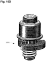
- FIG. 10A is an exploded view of a locking mechanism 1016, which can be tightened after the connection is made between the driveline cable-side connector and the device-side connector to lock the two connectors together.
- the locking mechanism can include an external housing 1046, o-ring 1048, screw or bolt 1050, and anti-rotational feature 1052.
- the o-ring can provide fluid sealing between the screw and the housing, and the anti-rotational feature can be configured to prevent the screw from loosening or unscrewing once the two connectors have been locked together.
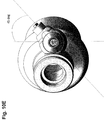
- FIG. 10B is a cross-sectional view of the locking mechanism 1016, showing the housing 1046, o-ring 1048, screw or bolt 1050, and anti-rotational feature 1052 joined together and inserted into the device-side connector.
- FIG. 10C shows an external view of the locking mechanism, showing that the screw 1050 includes a male screw pattern that mates with a female driver to screw in the screw 1050. This male design avoids the use of any holes or depressions which could otherwise promote tissue ingrowth into the locking mechanism.
- FIG. 10D is another view of the anti-rotational feature 1052.
- the feature can include two cantilevered-edges that compress when the screw is screwed down upon the anti-rotational feature. This design helps to maintain the screw in position since an increased torque is required to overcome the cantilevered-edges.
- FIG. 10E illustrates how the locking mechanism and the device-side connector can be angled off the implanted device so as to aid in access to the locking mechanism and connector.
- the locking mechanism can be angled at approximately 45 degrees from a horizontal plane extending through the device.
Landscapes
- Health & Medical Sciences (AREA)
- Engineering & Computer Science (AREA)
- Heart & Thoracic Surgery (AREA)
- Cardiology (AREA)
- Biomedical Technology (AREA)
- Mechanical Engineering (AREA)
- Anesthesiology (AREA)
- Hematology (AREA)
- Life Sciences & Earth Sciences (AREA)
- Animal Behavior & Ethology (AREA)
- General Health & Medical Sciences (AREA)
- Public Health (AREA)
- Veterinary Medicine (AREA)
- Power Engineering (AREA)
- Vascular Medicine (AREA)
- Computer Networks & Wireless Communication (AREA)
- Electrotherapy Devices (AREA)
Claims (4)
- Mehrachsiger Verbinder zum Verbinden einer ersten implantierten Vorrichtung mit einer zweiten implantierten Vorrichtung, dadurch gekennzeichnet, dass er Folgendes umfasst:einen kabelseitigen Antriebsleitung-Buchsenverbinder (706), beinhaltend:ein Lumen;einen gabelförmigen Feineinstellungs-Platin-Iridium-Verbinder (736), der in dem Lumen angeordnet ist;einen O-Ring (734a), der eine Innenwand des Lumens umgibt;ein erstes hervorstehendes taktiles Rückkopplungselement (730);einen geräteseitigen Steckerverbinder, beinhaltend:einen elektrischen Platin-Iridium-Stift (818), der konfiguriert ist, um in den gabelförmigen Feineinstellungs-Platin-Iridium-Verbinder eingesetzt zu werden, um eine elektrische Verbindung dazwischen herzustellen;eine Keramikhülle (820), die einen Abschnitt des elektrischen Platin-Iridium-Stifts abdeckt, wobei die Keramikhülle konfiguriert ist, um eine elektrische Isolierung für den elektrischen Stift aus Platin-Iridium bereitzustellen, wobei die Keramikhülle ferner konfiguriert ist, um in den O-Ring einzugreifen, um zu verhindern, dass Fluid die elektrische Verbindung unterbricht;ein zweites hervorstehendes taktiles Rückkopplungselement (624), das konfiguriert ist, um das erste hervorstehende taktile Rückkopplungselement einzugreifen zu kommen, um einem Benutzer eine taktile Antwort zu geben, wenn die elektrische Verbindung hergestellt ist;einen Verriegelungsmechanismus, der konfiguriert ist, um den kabelseitigen Antriebsleitung-Buchsenverbinder an dem geräteseitigen Steckerverbinder zu befestigen.
- Mehrachsiger Verbinder nach Anspruch 1, wobei die erste implantierte Vorrichtung eine LVAD-Pumpe umfasst.
- Mehrachsiger Verbinder nach Anspruch 1, wobei die zweite implantierte Vorrichtung einen drahtlosen Leistungsempfänger umfasst.
- Mehrachsiger Verbinder nach Anspruch 1, wobei der geräteseitige Steckerverbinder ferner einen Pumpensockel umfasst, der konfiguriert ist, um ein zur Umgebung abgedichtetes Gehäuse für den elektrischen Platin-Iridium-Stift bereitzustellen.
Applications Claiming Priority (2)
| Application Number | Priority Date | Filing Date | Title |
|---|---|---|---|
| US201462060435P | 2014-10-06 | 2014-10-06 | |
| PCT/US2015/054258 WO2016057525A1 (en) | 2014-10-06 | 2015-10-06 | Multiaxial connector for implantable devices |
Publications (3)
| Publication Number | Publication Date |
|---|---|
| EP3204989A1 EP3204989A1 (de) | 2017-08-16 |
| EP3204989A4 EP3204989A4 (de) | 2018-05-30 |
| EP3204989B1 true EP3204989B1 (de) | 2019-08-21 |
Family
ID=55653650
Family Applications (1)
| Application Number | Title | Priority Date | Filing Date |
|---|---|---|---|
| EP15848830.4A Not-in-force EP3204989B1 (de) | 2014-10-06 | 2015-10-06 | Mehrachsiger steckverbinder für implantierbare vorrichtungen |
Country Status (3)
| Country | Link |
|---|---|
| US (2) | US9583874B2 (de) |
| EP (1) | EP3204989B1 (de) |
| WO (1) | WO2016057525A1 (de) |
Families Citing this family (26)
| Publication number | Priority date | Publication date | Assignee | Title |
|---|---|---|---|---|
| US9855376B2 (en) | 2014-07-25 | 2018-01-02 | Minnetronix, Inc. | Power scaling |
| DE102015112098A1 (de) | 2014-07-25 | 2016-01-28 | Minnetronix, Inc. | Spulenparameter und Steuerung |
| US10342908B2 (en) | 2015-01-14 | 2019-07-09 | Minnetronix, Inc. | Distributed transformer |
| US10406267B2 (en) | 2015-01-16 | 2019-09-10 | Minnetronix, Inc. | Data communication in a transcutaneous energy transfer system |
| US10193395B2 (en) | 2015-04-14 | 2019-01-29 | Minnetronix, Inc. | Repeater resonator |
| DE102016106683A1 (de) * | 2015-04-14 | 2016-10-20 | Minnetronix, Inc | Implantierbares Stromversorgungsteil |
| KR101656723B1 (ko) * | 2015-06-30 | 2016-09-12 | 재단법인 오송첨단의료산업진흥재단 | 피드스루 제조방법 |
| AU2016363021A1 (en) | 2015-12-04 | 2018-05-31 | Qidni Labs, Inc. | An implantable renal replacement therapy |
| EP4732889A2 (de) | 2017-06-07 | 2026-04-29 | Supira Medical, Inc. | Vorrichtungen, systeme und verfahren zur bewegung intravaskulärer flüssigkeiten |
| US11511103B2 (en) | 2017-11-13 | 2022-11-29 | Shifamed Holdings, Llc | Intravascular fluid movement devices, systems, and methods of use |
| JP7410034B2 (ja) | 2018-02-01 | 2024-01-09 | シファメド・ホールディングス・エルエルシー | 血管内血液ポンプならびに使用および製造の方法 |
| US11389641B2 (en) * | 2018-03-21 | 2022-07-19 | Tc1 Llc | Modular flying lead cable and methods for use with heart pump controllers |
| WO2020028537A1 (en) | 2018-07-31 | 2020-02-06 | Shifamed Holdings, Llc | Intravascaular blood pumps and methods of use |
| WO2020073047A1 (en) | 2018-10-05 | 2020-04-09 | Shifamed Holdings, Llc | Intravascular blood pumps and methods of use |
| WO2021011473A1 (en) | 2019-07-12 | 2021-01-21 | Shifamed Holdings, Llc | Intravascular blood pumps and methods of manufacture and use |
| US11654275B2 (en) | 2019-07-22 | 2023-05-23 | Shifamed Holdings, Llc | Intravascular blood pumps with struts and methods of use and manufacture |
| EP4010046A4 (de) | 2019-08-07 | 2023-08-30 | Calomeni, Michael | Katheterblutpumpen und zusammenklappbare pumpengehäuse |
| EP4034221B1 (de) | 2019-09-25 | 2024-11-13 | Shifamed Holdings, LLC | Katheterblutpumpen und zusammenklappbare pumpengehäuse |
| EP4034192B1 (de) | 2019-09-25 | 2025-12-24 | Supira Medical, Inc. | Intravaskuläre blutpumpensysteme und verfahren zur verwendung und steuerung davon |
| WO2021062260A1 (en) | 2019-09-25 | 2021-04-01 | Shifamed Holdings, Llc | Catheter blood pumps and collapsible blood conduits |
| EP4072650A4 (de) | 2019-12-11 | 2024-01-10 | Shifamed Holdings, LLC | Absteigende aorten- und hohlvenenblutpumpen |
| US12599758B2 (en) | 2019-12-19 | 2026-04-14 | Shifamed Holdings, Llc | Intravascular blood pumps, motors, and fluid control |
| JP7713951B2 (ja) * | 2020-03-10 | 2025-07-28 | ティーシー1 エルエルシー | 心室補助装置に無線電力伝送するシステム及び方法 |
| US20220133965A1 (en) * | 2020-11-02 | 2022-05-05 | Medtronic, Inc. | Interconnect design for joining dissimilar materials |
| US12230975B2 (en) * | 2022-06-03 | 2025-02-18 | Deere & Company | Assembly for contactless transfer of electrical energy to a rotor |
| EP4507133A1 (de) | 2023-08-09 | 2025-02-12 | Berlin Heart GmbH | Implantierbarer elektrischer steckverbinder |
Family Cites Families (304)
| Publication number | Priority date | Publication date | Assignee | Title |
|---|---|---|---|---|
| US4041955A (en) | 1976-01-29 | 1977-08-16 | Pacesetter Systems Inc. | Implantable living tissue stimulator with an improved hermetic metal container |
| US4352960A (en) | 1980-09-30 | 1982-10-05 | Baptist Medical Center Of Oklahoma, Inc. | Magnetic transcutaneous mount for external device of an associated implant |
| US4561444A (en) | 1981-08-10 | 1985-12-31 | Cordis Corporation | Implantable cardiac pacer having dual frequency programming and bipolar/linipolar lead programmability |
| US4561443A (en) | 1983-03-08 | 1985-12-31 | The Johns Hopkins University | Coherent inductive communications link for biomedical applications |
| US4630615A (en) | 1984-05-21 | 1986-12-23 | Cordis Corporation | Apparatus for measuring impedance |
| US4679560A (en) | 1985-04-02 | 1987-07-14 | Board Of Trustees Of The Leland Stanford Junior University | Wide band inductive transdermal power and data link |
| US4726378A (en) | 1986-04-11 | 1988-02-23 | Minnesota Mining And Manufacturing Company | Adjustable magnetic supercutaneous device and transcutaneous coupling apparatus |
| US4736747A (en) | 1986-04-11 | 1988-04-12 | Minnesota Mining And Manufacturing Company | Adjustable magnetic supercutaneous device and transcutaneous coupling apparatus |
| US4945305A (en) | 1986-10-09 | 1990-07-31 | Ascension Technology Corporation | Device for quantitatively measuring the relative position and orientation of two bodies in the presence of metals utilizing direct current magnetic fields |
| JP2597623B2 (ja) | 1987-10-08 | 1997-04-09 | 株式会社トキメック | 電磁誘導結合による電源供給方式 |
| US5070223A (en) | 1989-03-01 | 1991-12-03 | Colasante David A | Microwave reheatable clothing and toys |
| JPH03109063A (ja) | 1989-09-22 | 1991-05-09 | Tanaka Kikinzoku Kogyo Kk | コネクター |
| US5350413B1 (en) | 1990-06-21 | 1999-09-07 | Heart Inst Research Corp | Transcutaneous energy transfer device |
| DE4020120A1 (de) | 1990-06-25 | 1991-01-31 | Klaus Prof Dr Ing Affeld | Medizinische vorrichtung zur erzeugung eines alternierenden volumenstroms fuer den antrieb von implantierbaren blutpumpen |
| CA2105781C (en) | 1992-09-14 | 2000-07-11 | Alton B. Otis, Jr. | Contactless communication system |
| WO1995007109A1 (en) | 1993-09-10 | 1995-03-16 | Ottawa Heart Institute Research Corporation | Electrohydraulic ventricular assist device |
| US5630836A (en) | 1995-01-19 | 1997-05-20 | Vascor, Inc. | Transcutaneous energy and information transmission apparatus |
| DE69630894T2 (de) | 1995-05-18 | 2004-09-02 | Aura Communications, Inc., Wilmington | Magnetisches kommunikationssystem mit geringer reichweite |
| US5690693A (en) | 1995-06-07 | 1997-11-25 | Sulzer Intermedics Inc. | Transcutaneous energy transmission circuit for implantable medical device |
| US5702431A (en) | 1995-06-07 | 1997-12-30 | Sulzer Intermedics Inc. | Enhanced transcutaneous recharging system for battery powered implantable medical device |
| JP3224508B2 (ja) | 1996-05-23 | 2001-10-29 | シャープ株式会社 | 加熱制御装置 |
| US5755748A (en) | 1996-07-24 | 1998-05-26 | Dew Engineering & Development Limited | Transcutaneous energy transfer device |
| US5733313A (en) | 1996-08-01 | 1998-03-31 | Exonix Corporation | RF coupled, implantable medical device with rechargeable back-up power source |
| US7107103B2 (en) | 1997-02-26 | 2006-09-12 | Alfred E. Mann Foundation For Scientific Research | Full-body charger for battery-powered patient implantable device |
| US6123726A (en) | 1997-07-25 | 2000-09-26 | Seiko Epson Corporation | Portable drive system for artificial heart |
| EP1019117B2 (de) | 1997-10-02 | 2015-03-18 | Micromed Technology, Inc. | Steuermodul für implantierbares Pumpsystem |
| US6324431B1 (en) | 1998-07-06 | 2001-11-27 | Abiomed, Inc. | Transcutaneous energy transfer device with magnetic field protected components in secondary coil |
| US8489200B2 (en) | 1998-07-06 | 2013-07-16 | Abiomed, Inc. | Transcutaneous energy transfer module with integrated conversion circuitry |
| US6389318B1 (en) | 1998-07-06 | 2002-05-14 | Abiomed, Inc. | Magnetic shield for primary coil of transcutaneous energy transfer device |
| US6634364B2 (en) | 2000-12-15 | 2003-10-21 | Cardiac Pacemakers, Inc. | Method of deploying a ventricular lead containing a hemostasis mechanism |
| US6296533B1 (en) | 1998-08-31 | 2001-10-02 | The Whitaker Corporation | Electrical receptacle contact |
| US6149683A (en) | 1998-10-05 | 2000-11-21 | Kriton Medical, Inc. | Power system for an implantable heart pump |
| US5948006A (en) | 1998-10-14 | 1999-09-07 | Advanced Bionics Corporation | Transcutaneous transmission patch |
| US6312338B1 (en) | 1998-10-21 | 2001-11-06 | Nintendo Company, Ltd. | Electronic accessory for game machine |
| US6212430B1 (en) | 1999-05-03 | 2001-04-03 | Abiomed, Inc. | Electromagnetic field source with detection of position of secondary coil in relation to multiple primary coils |
| US6146325A (en) | 1999-06-03 | 2000-11-14 | Arrow International, Inc. | Ventricular assist device |
| US7522878B2 (en) | 1999-06-21 | 2009-04-21 | Access Business Group International Llc | Adaptive inductive power supply with communication |
| US6553263B1 (en) | 1999-07-30 | 2003-04-22 | Advanced Bionics Corporation | Implantable pulse generators using rechargeable zero-volt technology lithium-ion batteries |
| US6442434B1 (en) | 1999-10-19 | 2002-08-27 | Abiomed, Inc. | Methods and apparatus for providing a sufficiently stable power to a load in an energy transfer system |
| WO2001037926A1 (en) | 1999-11-22 | 2001-05-31 | Abiomed, Inc. | Apparatus for transferring energy across a boundary |
| US8155752B2 (en) | 2000-03-17 | 2012-04-10 | Boston Scientific Neuromodulation Corporation | Implantable medical device with single coil for charging and communicating |
| US6895281B1 (en) | 2000-03-31 | 2005-05-17 | Cardiac Pacemakers, Inc. | Inductive coil apparatus for bio-medical telemetry |
| AU3949800A (en) | 2000-04-20 | 2001-11-07 | Cochlear Limited | Transcutaneous power optimization circuit for cochlear implant |
| US6458164B1 (en) | 2000-04-25 | 2002-10-01 | The Penn State Research Foundation | Artificial heart with energy recovery |
| US6478820B1 (en) | 2000-04-25 | 2002-11-12 | The Penn State Research Foundation | Artificial heart with synchronous rectification |
| US6451055B1 (en) | 2000-04-25 | 2002-09-17 | The Penn State Research Foundation | Artificial heart data communication system |
| US6579315B1 (en) | 2000-04-25 | 2003-06-17 | The Penn State Research Foundation | Artificial heart power supply system |
| US7167756B1 (en) | 2000-04-28 | 2007-01-23 | Medtronic, Inc. | Battery recharge management for an implantable medical device |
| US6327504B1 (en) | 2000-05-10 | 2001-12-04 | Thoratec Corporation | Transcutaneous energy transfer with circuitry arranged to avoid overheating |
| US6650213B1 (en) | 2000-06-02 | 2003-11-18 | Yamatake Corporation | Electromagnetic-induction coupling apparatus |
| US6850803B1 (en) | 2000-06-16 | 2005-02-01 | Medtronic, Inc. | Implantable medical device with a recharging coil magnetic shield |
| DE60140025D1 (de) | 2000-06-19 | 2009-11-12 | Medtronic Inc | Implantierbares medizinisches Gerät mit einer externen Nachladespule |
| US6320354B1 (en) | 2000-07-21 | 2001-11-20 | Motorola, Inc. | Method and apparatus for battery charging |
| US6591139B2 (en) | 2000-09-06 | 2003-07-08 | Advanced Bionics Corporation | Low-power, high-modulation-index amplifier for use in battery-powered device |
| JP2002185238A (ja) | 2000-12-11 | 2002-06-28 | Sony Corp | デュアルバンド対応内蔵アンテナ装置およびこれを備えた携帯無線端末 |
| US20020087204A1 (en) | 2001-01-04 | 2002-07-04 | Kung Robert T. V. | Flexible transcutaneous energy transfer (TET) primary coil |
| SE0100284D0 (sv) | 2001-01-31 | 2001-01-31 | St Jude Medical | Medical communication system |
| US7142811B2 (en) | 2001-03-16 | 2006-11-28 | Aura Communications Technology, Inc. | Wireless communication over a transducer device |
| US7532901B1 (en) | 2001-03-16 | 2009-05-12 | Radeum, Inc. | Methods and apparatus to detect location and orientation in an inductive system |
| DE10119691A1 (de) | 2001-04-20 | 2002-11-21 | Deutsch Zentr Luft & Raumfahrt | System zum Unterstützen des linken Herzventrikels |
| US7126310B1 (en) | 2001-04-20 | 2006-10-24 | Abiomed, Inc. | Apparatus and method for balanced charging of a multiple-cell battery pack |
| US6723039B2 (en) | 2001-04-27 | 2004-04-20 | The Foundry, Inc. | Methods, systems and devices relating to implantable fluid pumps |
| KR100606307B1 (ko) | 2001-05-23 | 2006-07-28 | 안태영 | 인체 이식 기구용 무접촉식 동력 전달 장치 |
| US6647298B2 (en) | 2001-06-04 | 2003-11-11 | St. Jude Medical Ab | Implantable medical device with variable incoming communication signal discrimination, and method for operating same |
| US6894456B2 (en) | 2001-11-07 | 2005-05-17 | Quallion Llc | Implantable medical power module |
| US6985773B2 (en) | 2002-02-07 | 2006-01-10 | Cardiac Pacemakers, Inc. | Methods and apparatuses for implantable medical device telemetry power management |
| US7565187B1 (en) | 2002-04-11 | 2009-07-21 | Radeum, Inc. | Transceiver device and fastener |
| JP3731881B2 (ja) | 2002-05-23 | 2006-01-05 | 有限会社ティーエム | 人工臓器用非侵襲式充電システム、並びにこのシステムに用いる蓄電装置、および給電装置 |
| US7515012B2 (en) | 2002-06-20 | 2009-04-07 | Alfred E. Mann Foundation For Scientific Research | System and method for automatic tuning of a magnetic field generator |
| US7015769B2 (en) | 2002-06-20 | 2006-03-21 | Alfred E. Mann Foundation For Scientific Research | System and method for automatic tuning of a magnetic field generator |
| US6960968B2 (en) | 2002-06-26 | 2005-11-01 | Koninklijke Philips Electronics N.V. | Planar resonator for wireless power transfer |
| US7437193B2 (en) | 2002-06-28 | 2008-10-14 | Boston Scientific Neuromodulation Corporation | Microstimulator employing improved recharging reporting and telemetry techniques |
| US7428438B2 (en) | 2002-06-28 | 2008-09-23 | Boston Scientific Neuromodulation Corporation | Systems and methods for providing power to a battery in an implantable stimulator |
| US6772011B2 (en) | 2002-08-20 | 2004-08-03 | Thoratec Corporation | Transmission of information from an implanted medical device |
| MXPA05002819A (es) | 2002-09-20 | 2005-06-03 | Potencia Medical Ag | Transmision de energia inalambrica inofensiva a implante. |
| DE10327500B4 (de) | 2003-06-17 | 2007-03-15 | W.C. Heraeus Gmbh | Verfahren zur Herstellung von Elektrodenstrukturen sowie Elektrodenstruktur und deren Verwendung |
| TWI257543B (en) | 2003-07-02 | 2006-07-01 | Delta Electronics Inc | Equalizing temperature device |
| US7818036B2 (en) | 2003-09-19 | 2010-10-19 | Radeum, Inc. | Techniques for wirelessly controlling push-to-talk operation of half-duplex wireless device |
| US7818037B2 (en) | 2003-09-19 | 2010-10-19 | Radeum, Inc. | Techniques for wirelessly controlling push-to-talk operation of half-duplex wireless device |
| US8265770B2 (en) | 2003-10-02 | 2012-09-11 | Medtronic, Inc. | Driver circuitry switchable between energy transfer and telemetry for an implantable medical device |
| US8140168B2 (en) | 2003-10-02 | 2012-03-20 | Medtronic, Inc. | External power source for an implantable medical device having an adjustable carrier frequency and system and method related therefore |
| US20050075696A1 (en) | 2003-10-02 | 2005-04-07 | Medtronic, Inc. | Inductively rechargeable external energy source, charger, system and method for a transcutaneous inductive charger for an implantable medical device |
| US7286880B2 (en) | 2003-10-02 | 2007-10-23 | Medtronic, Inc. | System and method for transcutaneous energy transfer achieving high efficiency |
| US7225032B2 (en) | 2003-10-02 | 2007-05-29 | Medtronic Inc. | External power source, charger and system for an implantable medical device having thermal characteristics and method therefore |
| DE10353943B4 (de) | 2003-11-18 | 2013-01-03 | Deutsches Zentrum für Luft- und Raumfahrt e.V. | Anordnung zur drahtlosen Energieübertragung an eine implantierte Einrichtung |
| US7471986B2 (en) | 2004-02-20 | 2008-12-30 | Cardiac Pacemakers, Inc. | System and method for transmitting energy to and establishing a communications network with one or more implanted devices |
| US6967621B1 (en) | 2004-03-16 | 2005-11-22 | The United States Of America As Represented By The Secretary Of The Army | Small low profile antennas using high impedance surfaces and high permeability, high permittivity materials |
| US7571007B2 (en) | 2004-04-12 | 2009-08-04 | Advanced Neuromodulation Systems, Inc. | Systems and methods for use in pulse generation |
| US7212110B1 (en) | 2004-04-19 | 2007-05-01 | Advanced Neuromodulation Systems, Inc. | Implantable device and system and method for wireless communication |
| US7325124B2 (en) | 2004-04-21 | 2008-01-29 | International Business Machines Corporation | System and method of execution of register pointer instructions ahead of instruction issue |
| CN1950914A (zh) | 2004-05-04 | 2007-04-18 | 皇家飞利浦电子股份有限公司 | 无线供电设备,可激励负载,无线系统以及用于无线能量传递的方法 |
| US7599743B2 (en) | 2004-06-24 | 2009-10-06 | Ethicon Endo-Surgery, Inc. | Low frequency transcutaneous energy transfer to implanted medical device |
| WO2006014687A1 (en) | 2004-07-20 | 2006-02-09 | Medtronic, Inc. | Switched power using telemetry in an implantable medical device |
| EP1794848A4 (de) | 2004-08-27 | 2010-11-24 | Pmi Ind Inc | Flexibler verbinder für einen implantierbaren kabelbaum |
| DE502005008173D1 (de) | 2004-09-15 | 2009-11-05 | Deutsch Zentr Luft & Raumfahrt | Verarbeitung von Fernerkundungsdaten |
| US7720546B2 (en) | 2004-09-30 | 2010-05-18 | Codman Neuro Sciences Sárl | Dual power supply switching circuitry for use in a closed system |
| EP1812094B1 (de) | 2004-11-16 | 2011-08-17 | Micromed Technology, Inc. | Datenmonitor auf Abstand für ein Herzpumpensystem |
| US8419609B2 (en) | 2005-10-05 | 2013-04-16 | Heartware Inc. | Impeller for a rotary ventricular assist device |
| US7699770B2 (en) | 2005-02-24 | 2010-04-20 | Ethicon Endo-Surgery, Inc. | Device for non-invasive measurement of fluid pressure in an adjustable restriction device |
| WO2006108304A1 (en) | 2005-04-11 | 2006-10-19 | Disetronic Licensing Ag | Web-enabled portable medical device |
| US7774069B2 (en) | 2005-04-29 | 2010-08-10 | Medtronic, Inc. | Alignment indication for transcutaneous energy transfer |
| US7505816B2 (en) | 2005-04-29 | 2009-03-17 | Medtronic, Inc. | Actively cooled external energy source, external charger, system of transcutaneous energy transfer, system of transcutaneous charging and method therefore |
| US20070096686A1 (en) | 2005-05-06 | 2007-05-03 | Medtronic, Inc. | Implantable device with heat absorption material |
| US7869858B2 (en) | 2005-05-12 | 2011-01-11 | General Electric Company | Patient table system and apparatus |
| US8112157B2 (en) | 2005-05-27 | 2012-02-07 | California Institute Of Technology | Magnetic material-containing microfabricated devices for wireless data and power transfer |
| US7825543B2 (en) | 2005-07-12 | 2010-11-02 | Massachusetts Institute Of Technology | Wireless energy transfer |
| KR101118710B1 (ko) | 2005-07-12 | 2012-03-13 | 메사추세츠 인스티튜트 오브 테크놀로지 | 무선 비-방사성 에너지 전달 |
| FR2889917A1 (fr) | 2005-09-01 | 2007-03-02 | Ela Medical Soc Par Actions Si | Equipement de telemetrie pour communiquer avec un dispositif actif implante dans une region du thorax d'un patient |
| US8792978B2 (en) | 2010-05-28 | 2014-07-29 | Lockheed Martin Corporation | Laser-based nerve stimulators for, E.G., hearing restoration in cochlear prostheses and method |
| US7590451B2 (en) | 2005-10-31 | 2009-09-15 | Medtronic, Inc. | Axial lead connector for implantable medical devices |
| WO2007053881A1 (en) | 2005-11-08 | 2007-05-18 | Ventrassist Pty Ltd | Improvements to control systems and power systems for rotary blood pumps |
| US7761164B2 (en) | 2005-11-30 | 2010-07-20 | Medtronic, Inc. | Communication system for medical devices |
| US7650192B2 (en) | 2005-12-02 | 2010-01-19 | Medtronic, Inc. | Passive charge of implantable medical device utilizing external power source and method |
| WO2007067825A1 (en) | 2005-12-07 | 2007-06-14 | Advanced Bionics Corporation | Battery protection and zero-volt battery recovery system for an implantable medical device |
| US20070142696A1 (en) | 2005-12-08 | 2007-06-21 | Ventrassist Pty Ltd | Implantable medical devices |
| DE102005059423A1 (de) | 2005-12-13 | 2007-06-21 | Airbus Deutschland Gmbh | Verfahren und Einrichtung zur redundanten Versorgung von mehreren elektrischen Stell-oder Antriebsmotoren durch eine gemeinsame Leistungselektronikeinheit |
| US7672732B2 (en) | 2006-03-31 | 2010-03-02 | University Of Pittsburgh - Of The Commonwealth System Of Higher Education | Portable apparatus that delivers power and information to implantable devices |
| JP4890953B2 (ja) | 2006-06-13 | 2012-03-07 | オリンパス株式会社 | カプセル内視鏡システム |
| US8103354B2 (en) | 2006-07-17 | 2012-01-24 | Advanced Bionics, Llc | Systems and methods for determining a threshold current level required to evoke a stapedial muscle reflex |
| DE102006035547A1 (de) | 2006-07-27 | 2008-02-21 | Deutsches Zentrum für Luft- und Raumfahrt e.V. | Übertragungs-Anordnung |
| JP2010503368A (ja) | 2006-09-01 | 2010-01-28 | パワーキャスト コーポレイション | ハイブリッドパワー取り出しおよび方法 |
| DE102006045928A1 (de) | 2006-09-28 | 2008-04-03 | Robert Bosch Gmbh | Anschlusssystem mit außenliegender Leitungsführung an Wischermotorgehäusen |
| US20100314946A1 (en) | 2006-10-26 | 2010-12-16 | Koninklijke Philips Electronics N.V. | Floor covering and inductive power system |
| US7365542B1 (en) | 2006-10-31 | 2008-04-29 | General Electric Company | Flexible RF coil assembly and method of making same |
| EP2882070B1 (de) | 2006-11-08 | 2016-08-31 | Panasonic Corporation | Kontaktlose Ladevorrichtung und kontaktloses Ladesystem |
| US8096954B2 (en) | 2006-11-29 | 2012-01-17 | Cardiac Pacemakers, Inc. | Adaptive sampling of heart sounds |
| KR100836536B1 (ko) | 2006-12-21 | 2008-06-10 | 한국과학기술원 | 컨덕터의 안테나에 대한 영향이 감소된 에스아이피 및 그설계 방법 |
| US20080167531A1 (en) | 2007-01-05 | 2008-07-10 | Cardiac Pacemakers, Inc. | System and method to monitor battery status in an implantable medical device |
| US7792588B2 (en) | 2007-01-26 | 2010-09-07 | Medtronic, Inc. | Radio frequency transponder based implantable medical system |
| US9774086B2 (en) | 2007-03-02 | 2017-09-26 | Qualcomm Incorporated | Wireless power apparatus and methods |
| US7932696B2 (en) | 2007-05-14 | 2011-04-26 | Boston Scientific Neuromodulation Corporation | Charger alignment indicator with adjustable threshold |
| US7830114B2 (en) | 2007-06-14 | 2010-11-09 | Visteon Global Technologies, Inc. | Flex circuit interface for wireless charging |
| US7812481B2 (en) | 2007-06-29 | 2010-10-12 | Seiko Epson Corporation | Power transmission control device, power transmission device, electronic instrument, and non-contact power transmission system |
| JP2010535392A (ja) | 2007-08-02 | 2010-11-18 | ユニバーシティ オブ ピッツバーグ オブ ザ コモンウェルス システム オブ ハイヤー エデュケーション | 複数の電子デバイスを有し、構築及び整合が簡素化されたワイヤレスシステム及び関連する方法 |
| CA2695932A1 (en) | 2007-08-08 | 2009-02-12 | Radeum, Inc. | Near field communications system having enhanced security |
| CN101842962B (zh) | 2007-08-09 | 2014-10-08 | 高通股份有限公司 | 增加谐振器的q因数 |
| WO2009023905A1 (en) | 2007-08-17 | 2009-02-26 | Ventrassist Pty Ltd | Transcutaneous energy transfer coil assemblies and systems |
| GB0716679D0 (en) | 2007-08-28 | 2007-10-03 | Fells J | Inductive power supply |
| WO2009032969A1 (en) | 2007-09-06 | 2009-03-12 | Smith & Nephew, Inc. | System and method for communicating with a telemetric implant |
| KR20120102173A (ko) | 2007-09-13 | 2012-09-17 | 퀄컴 인코포레이티드 | 무선 전력 인가를 위한 안테나 |
| EP2188863A1 (de) | 2007-09-13 | 2010-05-26 | QUALCOMM Incorporated | Maximierung des pulverertrags aus drahtlosen leistungsmagnetresonatoren |
| EP2201641A1 (de) | 2007-09-17 | 2010-06-30 | Qualcomm Incorporated | Sender und empfänger für drahtlosen energietransfer |
| CA2700991A1 (en) | 2007-09-26 | 2009-04-02 | Radeum, Inc. Dba Freelinc | System and method for near field communications having local security |
| WO2009051538A1 (en) | 2007-10-16 | 2009-04-23 | Milux Holding Sa | A method and apparatus for supplying energy to a medical device |
| MX2010004087A (es) | 2007-10-16 | 2010-08-11 | Milux Holding Sa | Metodo y aparato para suministrar energia a un dispositivo medico. |
| US8244367B2 (en) | 2007-10-26 | 2012-08-14 | Medtronic, Inc. | Closed loop long range recharging |
| ATE509661T1 (de) | 2007-10-26 | 2011-06-15 | Medtronic Inc | Verfahren und gerät zur dynamischen einstellung von wiederaufladeparametern |
| US7960867B2 (en) | 2007-11-27 | 2011-06-14 | Extremely Ingenious Engineering | Methods and systems for wireless energy and data transmission |
| CN103259344B (zh) | 2007-12-21 | 2016-08-10 | 捷通国际有限公司 | 用于感应功率传输的电路 |
| KR101061661B1 (ko) | 2008-01-09 | 2011-09-01 | 세이코 엡슨 가부시키가이샤 | 송전 제어 장치, 송전 장치, 무접점 전력 전송 시스템, 전자 기기 및 송전 제어 방법 |
| NZ565234A (en) | 2008-01-18 | 2010-11-26 | Telemetry Res Ltd | Selectable resonant frequency transcutaneous energy transfer system |
| US8165694B2 (en) | 2008-01-29 | 2012-04-24 | Boston Scientific Neuromodulation Corporation | Thermal management of implantable medical devices |
| CA2715916A1 (en) | 2008-02-22 | 2009-08-27 | David W. Baarman | Inductive power supply system with battery type detection |
| ES2556269T3 (es) | 2008-04-03 | 2016-01-14 | Koninklijke Philips N.V. | Sistema inalámbrico de transmisión de energía |
| US8150529B2 (en) | 2008-04-16 | 2012-04-03 | Pacesetter, Inc. | Medical devices and systems having separate power sources for enabling different telemetry systems |
| JP2009268181A (ja) | 2008-04-22 | 2009-11-12 | Olympus Corp | エネルギー供給装置 |
| US9526407B2 (en) | 2008-04-25 | 2016-12-27 | Karl Storz Imaging, Inc. | Wirelessly powered medical devices and instruments |
| US8193766B2 (en) | 2008-04-30 | 2012-06-05 | Medtronic, Inc. | Time remaining to charge an implantable medical device, charger indicator, system and method therefore |
| US8081925B2 (en) | 2008-05-08 | 2011-12-20 | Boston Scientific Neuromodulation Corporation | Transceiver for an implantable medical device having switchable series-to-parallel tank circuit |
| US8629650B2 (en) | 2008-05-13 | 2014-01-14 | Qualcomm Incorporated | Wireless power transfer using multiple transmit antennas |
| WO2009140506A1 (en) | 2008-05-14 | 2009-11-19 | Massachusetts Institute Of Technology | Wireless energy transfer, including interference enhancement |
| JP4698702B2 (ja) | 2008-05-22 | 2011-06-08 | 三菱電機株式会社 | 電子機器 |
| US20100019985A1 (en) | 2008-07-24 | 2010-01-28 | Jacob Bashyam | Header with integral antenna for implantable medical devices |
| US8278784B2 (en) | 2008-07-28 | 2012-10-02 | Qualcomm Incorporated | Wireless power transmission for electronic devices |
| US8111042B2 (en) | 2008-08-05 | 2012-02-07 | Broadcom Corporation | Integrated wireless resonant power charging and communication channel |
| US7893564B2 (en) | 2008-08-05 | 2011-02-22 | Broadcom Corporation | Phased array wireless resonant power delivery system |
| US20100045114A1 (en) | 2008-08-20 | 2010-02-25 | Sample Alanson P | Adaptive wireless power transfer apparatus and method thereof |
| US8299652B2 (en) | 2008-08-20 | 2012-10-30 | Intel Corporation | Wireless power transfer apparatus and method thereof |
| US9473209B2 (en) | 2008-08-20 | 2016-10-18 | Intel Corporation | Wireless power transfer apparatus and method thereof |
| US8581542B2 (en) | 2008-09-08 | 2013-11-12 | Qualcomm Incorporated | Receive antenna arrangement for wireless power |
| CN102149425B (zh) | 2008-09-10 | 2014-11-05 | 海德威公司 | 用于植入医疗设备的tet系统 |
| US8532724B2 (en) | 2008-09-17 | 2013-09-10 | Qualcomm Incorporated | Transmitters for wireless power transmission |
| US9577436B2 (en) | 2008-09-27 | 2017-02-21 | Witricity Corporation | Wireless energy transfer for implantable devices |
| US9515494B2 (en) | 2008-09-27 | 2016-12-06 | Witricity Corporation | Wireless power system including impedance matching network |
| US8772973B2 (en) | 2008-09-27 | 2014-07-08 | Witricity Corporation | Integrated resonator-shield structures |
| US8629578B2 (en) | 2008-09-27 | 2014-01-14 | Witricity Corporation | Wireless energy transfer systems |
| US20100277121A1 (en) | 2008-09-27 | 2010-11-04 | Hall Katherine L | Wireless energy transfer between a source and a vehicle |
| US8692410B2 (en) | 2008-09-27 | 2014-04-08 | Witricity Corporation | Wireless energy transfer with frequency hopping |
| US9184595B2 (en) | 2008-09-27 | 2015-11-10 | Witricity Corporation | Wireless energy transfer in lossy environments |
| SE0901000A2 (en) | 2008-10-10 | 2010-07-20 | Milux Holding Sa | A voice control system for an implant |
| US20100114143A1 (en) | 2008-10-30 | 2010-05-06 | Albrecht Thomas E | Wearable elements for intra-gastric satiety creations systems |
| US8497804B2 (en) | 2008-10-31 | 2013-07-30 | Medtronic, Inc. | High dielectric substrate antenna for implantable miniaturized wireless communications and method for forming the same |
| JP5114364B2 (ja) | 2008-11-04 | 2013-01-09 | 株式会社豊田自動織機 | 非接触電力伝送装置及びその設計方法 |
| CA2744045A1 (en) | 2008-11-18 | 2010-05-27 | Thoratec Corporation | Medical device accessory carrier |
| US8810194B2 (en) | 2008-11-20 | 2014-08-19 | Qualcomm Incorporated | Retrofitting wireless power and near-field communication in electronic devices |
| EP2385805A4 (de) | 2008-11-21 | 2012-10-17 | Milux Holding Sa | Energieversorgungssystem |
| NZ593750A (en) | 2009-01-06 | 2013-09-27 | Access Business Group Int Llc | Inductive power supply |
| JP5425539B2 (ja) | 2009-01-27 | 2014-02-26 | パナソニック株式会社 | 非接触電力伝送システム |
| DE102009007464B4 (de) | 2009-02-04 | 2023-12-21 | Intel Deutschland Gmbh | Ermittlungseinrichtung, Verfahren zum Ermitteln eines Übertragungsparameters, Energieübertragungseinrichtung und Verfahren zum drahtlosen Übertragen von Energie |
| US20100225174A1 (en) | 2009-03-05 | 2010-09-09 | Hao Jiang | Wireless Power Transfer Using Magnets |
| US8803474B2 (en) | 2009-03-25 | 2014-08-12 | Qualcomm Incorporated | Optimization of wireless power devices |
| EP2416470B1 (de) | 2009-03-30 | 2019-11-13 | Fujitsu Limited | Drahtloses stromversorgungssystem, drahtlose stromübertragungseinrichtung und drahtlose stromempfangseinrichtung |
| DE112010001536T5 (de) | 2009-04-02 | 2012-06-14 | Regents Of The University Of Minnesota | Adiabatische magnetisierungsvorbereitung für b1- und b0-unempfindliche mri mit hohemkontrast |
| US8326426B2 (en) | 2009-04-03 | 2012-12-04 | Enteromedics, Inc. | Implantable device with heat storage |
| JP5447509B2 (ja) | 2009-04-27 | 2014-03-19 | 株式会社村田製作所 | ワイヤレス電力伝送端末 |
| RU2573184C2 (ru) | 2009-05-15 | 2016-01-20 | Конинклейке Филипс Электроникс Н.В. | Имплантируемое устройство со средствами связи |
| EP2433347B1 (de) | 2009-05-20 | 2013-10-23 | Koninklijke Philips N.V. | Elektronische vorrichtung aufweisend induktive empfangsspule mit ultradünner abschirmungsschicht und verfahren |
| US8214042B2 (en) | 2009-05-26 | 2012-07-03 | Boston Scientific Neuromodulation Corporation | Techniques for controlling charging of batteries in an external charger and an implantable medical device |
| JP2011010444A (ja) | 2009-06-25 | 2011-01-13 | Panasonic Electric Works Co Ltd | 非接触充電器 |
| US20100331919A1 (en) | 2009-06-30 | 2010-12-30 | Boston Scientific Neuromodulation Corporation | Moldable charger having hinged sections for charging an implantable pulse generator |
| US8473066B2 (en) | 2009-07-06 | 2013-06-25 | Boston Scientific Neuromodulation Company | External charger for a medical implantable device using field sensing coils to improve coupling |
| US8229573B2 (en) | 2009-07-21 | 2012-07-24 | Boston Scientific Neuromodulation Corporation | Spring passive lead anchor and methods and devices using the anchor |
| WO2011010375A1 (ja) | 2009-07-23 | 2011-01-27 | 富士通株式会社 | 送電装置、無線電力供給システム、および無線電力供給装置 |
| US8581793B2 (en) | 2009-08-05 | 2013-11-12 | William N. Carr | RFID antenna with asymmetrical structure and method of making same |
| US9782600B2 (en) | 2009-08-20 | 2017-10-10 | Envoy Medical Corporation | Self-regulating transcutaneous energy transfer |
| US8928284B2 (en) | 2009-09-10 | 2015-01-06 | Qualcomm Incorporated | Variable wireless power transmission |
| US8628460B2 (en) | 2009-09-21 | 2014-01-14 | Heartware, Inc. | Hard-wired implanted controller system |
| JP5459058B2 (ja) | 2009-11-09 | 2014-04-02 | 株式会社豊田自動織機 | 共鳴型非接触電力伝送装置 |
| US8547057B2 (en) | 2009-11-17 | 2013-10-01 | Qualcomm Incorporated | Systems and methods for selective wireless power transfer |
| KR101730824B1 (ko) | 2009-11-30 | 2017-04-27 | 삼성전자주식회사 | 무선 전력 트랜시버 및 무선 전력 시스템 |
| US8143746B2 (en) | 2009-12-21 | 2012-03-27 | Alcatel Lucent | Automatic tuning for wireless power transfer |
| WO2011077488A1 (ja) | 2009-12-24 | 2011-06-30 | 株式会社 東芝 | 無線電力伝送装置 |
| WO2011081626A1 (en) | 2009-12-30 | 2011-07-07 | Thoratec Corporation | Mobility-enhancing blood pump system |
| US8562508B2 (en) | 2009-12-30 | 2013-10-22 | Thoratec Corporation | Mobility-enhancing blood pump system |
| GB201000662D0 (en) | 2010-01-15 | 2010-03-03 | Wireless Fibre Systems Ltd | Subsea wireless communication, navigation and power system |
| EP2525870B1 (de) | 2010-01-19 | 2019-03-13 | Heartware, Inc. | Physiologisch reagierendes ventrikuläres unterstützungssystem |
| US9153993B2 (en) | 2010-01-26 | 2015-10-06 | Broadcom Corporation | Smart charging system and related method |
| WO2011097289A1 (en) | 2010-02-03 | 2011-08-11 | Medtronic, Inc. | Implantable medical devices and systems having dual frequency inductive telemetry and recharge |
| DE102010011940B4 (de) | 2010-03-18 | 2018-02-01 | Deutsches Zentrum für Luft- und Raumfahrt e.V. | Vorrichtung zur Energieversorgung von hydraulisch oder pneumatisch aktuierten aktiven Implantaten |
| US9030159B2 (en) | 2010-03-26 | 2015-05-12 | Boston Scientific Neuromodulation Corporation | Inductive charger with magnetic shielding |
| US8791601B2 (en) | 2010-04-02 | 2014-07-29 | Advantest Corporation | Wireless power receiving apparatus and wireless power supply system |
| KR20110111796A (ko) | 2010-04-05 | 2011-10-12 | 삼성전기주식회사 | 무선 에너지 전송 구조체 |
| US9216297B2 (en) | 2010-04-05 | 2015-12-22 | Medtronic, Inc. | Flexible recharge coil techniques |
| KR101744162B1 (ko) | 2010-05-03 | 2017-06-07 | 삼성전자주식회사 | 소스-타겟 구조의 매칭을 제어하는 장치 및 방법 |
| US20110276110A1 (en) | 2010-05-07 | 2011-11-10 | Boston Scientific Neuromodulation Corporation | Power Circuitry for an Implantable Medical Device Using a DC-DC Converter |
| EP2568879A4 (de) | 2010-05-13 | 2014-09-10 | Sensible Medical Innovations Ltd | Verfahren und system zur verwendung einer verteilten elektromagnetischen gewebeüberwachung |
| US8704484B2 (en) | 2010-05-28 | 2014-04-22 | Qualcomm Incorporated | Temperature sensor interface for wireless and wired charging |
| TWI389416B (zh) | 2010-05-31 | 2013-03-11 | 富達通科技股份有限公司 | Power transmission method of high power wireless inductive power supply |
| TW201212959A (en) | 2010-06-22 | 2012-04-01 | Thoratec Corp | Fluid delivery system and method for monitoring fluid delivery system |
| US8292052B2 (en) | 2010-06-24 | 2012-10-23 | General Electric Company | Power transfer system and method |
| JP2012016125A (ja) | 2010-06-30 | 2012-01-19 | Panasonic Electric Works Co Ltd | 非接触給電システム及び非接触給電システムの金属異物検出装置 |
| KR101545133B1 (ko) | 2010-07-14 | 2015-08-20 | 한국전기연구원 | 생체 내 센서를 위한 무선전력전송 시스템 및 그 방법 |
| US8901775B2 (en) | 2010-12-10 | 2014-12-02 | Everheart Systems, Inc. | Implantable wireless power system |
| KR20120040618A (ko) | 2010-10-19 | 2012-04-27 | 손현여 | 무선전력전송 충전시 전력의 세기와 충전 완료 시간을 표시하는 장치 및 방법 |
| US9166655B2 (en) | 2010-10-28 | 2015-10-20 | Cochlear Limited | Magnetic induction communication system for an implantable medical device |
| JP2014501034A (ja) | 2010-10-28 | 2014-01-16 | コーニンクレッカ フィリップス エヌ ヴェ | 無線電力供給ユニット、及び、光透過性カバーと照明システムとを有する配置 |
| US20120104997A1 (en) | 2010-11-01 | 2012-05-03 | Qualcomm Incorporated | Wireless charging device |
| JP5784300B2 (ja) | 2010-11-17 | 2015-09-24 | 株式会社東芝 | Rfコイル装置、および、磁気共鳴イメージング装置 |
| CA2820886A1 (en) * | 2010-12-08 | 2012-06-14 | Thoratec Corporation | Modular driveline |
| US9132276B2 (en) | 2010-12-10 | 2015-09-15 | Cochlear Limited | Portable power charging of implantable medical devices |
| US9496924B2 (en) | 2010-12-10 | 2016-11-15 | Everheart Systems, Inc. | Mobile wireless power system |
| ES2731918T3 (es) | 2010-12-20 | 2019-11-19 | Abiomed Inc | Sistema de transferencia de energía transcutánea con bobinas secundarias múltiples |
| US8766788B2 (en) | 2010-12-20 | 2014-07-01 | Abiomed, Inc. | Transcutaneous energy transfer system with vibration inducing warning circuitry |
| US20120157754A1 (en) | 2010-12-20 | 2012-06-21 | Abiomed, Inc. | Compact battery and controller module for a transcutaneous energy transfer system |
| DK2654883T3 (da) | 2010-12-20 | 2022-10-10 | Abiomed Inc | Fremgangsmåde og apparat til nøjagtig overvågning af tilgængelig ladning i et transkutant energioverførselssystem |
| US20120153739A1 (en) | 2010-12-21 | 2012-06-21 | Cooper Emily B | Range adaptation mechanism for wireless power transfer |
| KR101739293B1 (ko) | 2010-12-23 | 2017-05-24 | 삼성전자주식회사 | 인 밴드 통신을 이용한 무선 전력 송수신 시스템 |
| US9246349B2 (en) | 2010-12-27 | 2016-01-26 | Golba Llc | Method and system for wireless battery charging utilizing ultrasonic transducer array based beamforming |
| US9077192B2 (en) | 2010-12-29 | 2015-07-07 | National Semiconductor Corporation | Transmitter and receiver tuning in a wireless charging system |
| US9203380B2 (en) | 2010-12-29 | 2015-12-01 | National Semiconductor Corporation | Resonance tuning |
| US9231412B2 (en) | 2010-12-29 | 2016-01-05 | National Semiconductor Corporation | Resonant system for wireless power transmission to multiple receivers |
| KR101183664B1 (ko) | 2010-12-30 | 2012-09-17 | 전자부품연구원 | 이물질을 감지할 수 있는 자기공진유도 방식을 이용한 무선 전력공급 장치 |
| JP2012143146A (ja) | 2011-01-03 | 2012-07-26 | Samsung Electronics Co Ltd | 無線電力送信装置及びその無線電力送信システム |
| US9178369B2 (en) | 2011-01-18 | 2015-11-03 | Mojo Mobility, Inc. | Systems and methods for providing positioning freedom, and support of different voltages, protocols, and power levels in a wireless power system |
| CN102094464B (zh) | 2011-03-18 | 2013-03-20 | 王镇生 | 压应力止水板 |
| US8849402B2 (en) | 2011-03-21 | 2014-09-30 | General Electric Company | System and method for contactless power transfer in implantable devices |
| US9166321B2 (en) | 2011-03-22 | 2015-10-20 | Greatbatch Ltd. | Thin profile stacked layer contact |
| WO2012141752A2 (en) | 2011-04-14 | 2012-10-18 | Abiomed Inc. | Transcutaneous energy transfer coil with integrated radio frequency antenna |
| US20120274148A1 (en) | 2011-04-27 | 2012-11-01 | Samsung Electro-Mechanics Co., Ltd. | Contactless power transmission device and electronic device having the same |
| US9391461B2 (en) | 2011-05-31 | 2016-07-12 | Samsung Electronics Co., Ltd. | Wireless power transmission and charging system, and power control method of wireless power transmission and charging system |
| JP5712289B2 (ja) | 2011-06-07 | 2015-05-07 | パイオニア株式会社 | インピーダンス整合装置、制御方法 |
| US20130197607A1 (en) | 2011-06-28 | 2013-08-01 | Greatbatch Ltd. | Dual patient controllers |
| US20130007949A1 (en) | 2011-07-08 | 2013-01-10 | Witricity Corporation | Wireless energy transfer for person worn peripherals |
| WO2013009881A2 (en) | 2011-07-11 | 2013-01-17 | Vascor, Inc. | Transcutaneous power transmission and communication for implanted heart assist and other devices |
| WO2013046040A2 (en) | 2011-09-30 | 2013-04-04 | Adi Mashiach | Apparatus and method for controlling energy delivery as a function of degree of coupling |
| US8887619B2 (en) | 2011-10-28 | 2014-11-18 | Medtronic, Inc. | Removable heat management for recharge coils |
| JP5899814B2 (ja) | 2011-11-01 | 2016-04-06 | 株式会社ニデック | 体内埋植装置 |
| HK1200602A1 (en) | 2011-11-04 | 2015-08-07 | WiTricity公司 | Wireless energy transfer modeling tool |
| US9118203B2 (en) | 2011-11-15 | 2015-08-25 | Qualcomm Incorporated | Systems and methods for induction charging with a closed magnetic loop |
| US9079043B2 (en) | 2011-11-21 | 2015-07-14 | Thoratec Corporation | Transcutaneous power transmission utilizing non-planar resonators |
| US8805301B2 (en) | 2011-12-09 | 2014-08-12 | Bae Systems Information And Electronic Systems Integration Inc. | Drop zone rally point beacon |
| US9002468B2 (en) | 2011-12-16 | 2015-04-07 | Abiomed, Inc. | Automatic power regulation for transcutaneous energy transfer charging system |
| DE202012000166U1 (de) | 2012-01-10 | 2013-04-12 | Dualis Medtech Gmbh | System zum Übertragen von Energie an eine implantierte Vorrichtung |
| WO2013112550A1 (en) * | 2012-01-24 | 2013-08-01 | Thoratec Corporation | Driveline cable assembly |
| DE102012201073B4 (de) | 2012-01-25 | 2014-05-08 | Dualis Medtech Gmbh | Tragevorrichtung zum Tragen einer Sendespule am Körper eines Patienten |
| JP5706352B2 (ja) | 2012-02-03 | 2015-04-22 | ヒロセ電機株式会社 | 電気コネクタ |
| US9744368B2 (en) | 2012-02-16 | 2017-08-29 | Medtronic, Inc. | Self-tuning external device for wirelessly recharging implantable medical devices |
| US9246214B2 (en) | 2012-03-08 | 2016-01-26 | Apple Inc. | Electronic device antenna structures with ferrite layers |
| CN104487131A (zh) | 2012-03-13 | 2015-04-01 | 阳光心脏有限公司 | 关于无线电力传输的方法系统和设备 |
| KR101868041B1 (ko) | 2012-04-16 | 2018-06-18 | 한국전자통신연구원 | 초음파 무선전력 송수신장치 및 그 무선충전 방법 |
| WO2013159235A1 (en) | 2012-04-27 | 2013-10-31 | Socovar S.E.C. | Wireless sensor network for measurement of electrical energy consumption |
| US8827889B2 (en) | 2012-05-21 | 2014-09-09 | University Of Washington Through Its Center For Commercialization | Method and system for powering implantable devices |
| KR20150028262A (ko) | 2012-06-11 | 2015-03-13 | 하트웨어, 인코포레이티드 | 정렬 특성부가 구비된 접착식 tet 코일 홀더 |
| US9225388B2 (en) | 2012-07-03 | 2015-12-29 | Intel Corporation | Transmitting magnetic field through metal chassis using fractal surfaces |
| US9592397B2 (en) | 2012-07-27 | 2017-03-14 | Thoratec Corporation | Thermal management for implantable wireless power transfer systems |
| EP2878060A4 (de) | 2012-07-27 | 2016-04-06 | Thoratec Corp | Drahtlose batterieaufladung |
| US10383990B2 (en) | 2012-07-27 | 2019-08-20 | Tc1 Llc | Variable capacitor for resonant power transfer systems |
| WO2014018967A1 (en) | 2012-07-27 | 2014-01-30 | Thoratec Corporation | Self-tuning resonant power transfer systems |
| WO2014018973A1 (en) | 2012-07-27 | 2014-01-30 | Thoratec Corporation | Resonant power transmission coils and systems |
| WO2014018971A1 (en) | 2012-07-27 | 2014-01-30 | Thoratec Corporation | Resonant power transfer systems with protective algorithm |
| US10525181B2 (en) | 2012-07-27 | 2020-01-07 | Tc1 Llc | Resonant power transfer system and method of estimating system state |
| US9805863B2 (en) | 2012-07-27 | 2017-10-31 | Thoratec Corporation | Magnetic power transmission utilizing phased transmitter coil arrays and phased receiver coil arrays |
| JP6268178B2 (ja) | 2012-09-05 | 2018-01-24 | ハートウェア, インコーポレイテッドHeartware, Inc. | Vadに一体化された流量センサ |
| US9391471B2 (en) | 2012-12-05 | 2016-07-12 | Lockheed Martin Corporation | Re-configurable coded inductive charging system |
| US9826963B2 (en) | 2012-12-07 | 2017-11-28 | Medtronic, Inc. | Minimally invasive implantable neurostimulation system |
| JP6182324B2 (ja) * | 2013-02-20 | 2017-08-16 | 日本航空電子工業株式会社 | 電動車両用電力コネクタ |
| US9919088B2 (en) | 2013-03-14 | 2018-03-20 | Yale University | Implantable heart pump controller |
| US10373756B2 (en) | 2013-03-15 | 2019-08-06 | Tc1 Llc | Malleable TETs coil with improved anatomical fit |
| WO2014145664A1 (en) | 2013-03-15 | 2014-09-18 | Thoratec Corporation | Integrated implantable tets housing including fins and coil loops |
| EP3069358B1 (de) | 2013-11-11 | 2019-06-12 | Tc1 Llc | Resonante stromübertragungsspule mit einem scharnier |
| EP3072210B1 (de) | 2013-11-11 | 2023-12-20 | Tc1 Llc | Resonante stromübertragungssysteme mit kommunikation |
| WO2015070200A1 (en) | 2013-11-11 | 2015-05-14 | Thoratec Corporation | Resonant power transfer systems with communications |
| CA2945711A1 (en) | 2014-04-15 | 2015-10-22 | Heartware, Inc. | Improvements in transcutaneous energy transfer systems |
| DE102014116537B4 (de) | 2014-11-12 | 2024-05-29 | Infineon Technologies Ag | Funktionales Hautpflaster sowie System zum Überwachen eines Körpergesundheitsparameters |
-
2015
- 2015-10-06 EP EP15848830.4A patent/EP3204989B1/de not_active Not-in-force
- 2015-10-06 WO PCT/US2015/054258 patent/WO2016057525A1/en not_active Ceased
- 2015-10-06 US US14/876,554 patent/US9583874B2/en not_active Expired - Fee Related
-
2017
- 2017-01-18 US US15/408,545 patent/US10265450B2/en not_active Expired - Fee Related
Non-Patent Citations (1)
| Title |
|---|
| None * |
Also Published As
| Publication number | Publication date |
|---|---|
| US20170119947A1 (en) | 2017-05-04 |
| US9583874B2 (en) | 2017-02-28 |
| WO2016057525A1 (en) | 2016-04-14 |
| EP3204989A1 (de) | 2017-08-16 |
| EP3204989A4 (de) | 2018-05-30 |
| US20160181730A1 (en) | 2016-06-23 |
| US10265450B2 (en) | 2019-04-23 |
Similar Documents
| Publication | Publication Date | Title |
|---|---|---|
| EP3204989B1 (de) | Mehrachsiger steckverbinder für implantierbare vorrichtungen | |
| US11239701B2 (en) | Resonant power transfer systems having efficiency optimization based on receiver impedance | |
| US10476317B2 (en) | Integrated implantable TETs housing including fins and coil loops | |
| US11245181B2 (en) | Antenna designs for communication between a wirelessly powered implant to an external device outside the body | |
| EP3069358B1 (de) | Resonante stromübertragungsspule mit einem scharnier | |
| EP3490102B1 (de) | Verformbare tets-spule mit verbesserter anatomischer passform | |
| EP3216468B1 (de) | Implantierbares drahtloses leistungssystem | |
| US9496924B2 (en) | Mobile wireless power system | |
| US20170271919A1 (en) | Wireless implant powering via subcutaneous power relay | |
| US20170214268A1 (en) | Physically-Configurable External Charger for an Implantable Medical Device with Separable Coil and Electronics Housings | |
| EP3535017A1 (de) | System zur drahtlosen in-vivo-kopplung | |
| US20170214127A1 (en) | Antenna deployment for medical implants | |
| US20180233940A1 (en) | Multi-axis power coupling | |
| WO2025144653A1 (en) | Systems and methods for wireless power transfer systems with improved coupling |
Legal Events
| Date | Code | Title | Description |
|---|---|---|---|
| STAA | Information on the status of an ep patent application or granted ep patent |
Free format text: STATUS: THE INTERNATIONAL PUBLICATION HAS BEEN MADE |
|
| PUAI | Public reference made under article 153(3) epc to a published international application that has entered the european phase |
Free format text: ORIGINAL CODE: 0009012 |
|
| STAA | Information on the status of an ep patent application or granted ep patent |
Free format text: STATUS: REQUEST FOR EXAMINATION WAS MADE |
|
| 17P | Request for examination filed |
Effective date: 20170329 |
|
| AK | Designated contracting states |
Kind code of ref document: A1 Designated state(s): AL AT BE BG CH CY CZ DE DK EE ES FI FR GB GR HR HU IE IS IT LI LT LU LV MC MK MT NL NO PL PT RO RS SE SI SK SM TR |
|
| AX | Request for extension of the european patent |
Extension state: BA ME |
|
| DAV | Request for validation of the european patent (deleted) | ||
| DAX | Request for extension of the european patent (deleted) | ||
| A4 | Supplementary search report drawn up and despatched |
Effective date: 20180502 |
|
| RIC1 | Information provided on ipc code assigned before grant |
Ipc: H01R 13/11 20060101ALI20180424BHEP Ipc: H01R 13/03 20060101AFI20180424BHEP Ipc: A61M 1/12 20060101ALI20180424BHEP |
|
| GRAP | Despatch of communication of intention to grant a patent |
Free format text: ORIGINAL CODE: EPIDOSNIGR1 |
|
| STAA | Information on the status of an ep patent application or granted ep patent |
Free format text: STATUS: GRANT OF PATENT IS INTENDED |
|
| INTG | Intention to grant announced |
Effective date: 20190319 |
|
| RAP1 | Party data changed (applicant data changed or rights of an application transferred) |
Owner name: TC1 LLC |
|
| GRAS | Grant fee paid |
Free format text: ORIGINAL CODE: EPIDOSNIGR3 |
|
| GRAA | (expected) grant |
Free format text: ORIGINAL CODE: 0009210 |
|
| STAA | Information on the status of an ep patent application or granted ep patent |
Free format text: STATUS: THE PATENT HAS BEEN GRANTED |
|
| AK | Designated contracting states |
Kind code of ref document: B1 Designated state(s): AL AT BE BG CH CY CZ DE DK EE ES FI FR GB GR HR HU IE IS IT LI LT LU LV MC MK MT NL NO PL PT RO RS SE SI SK SM TR |
|
| REG | Reference to a national code |
Ref country code: GB Ref legal event code: FG4D |
|
| REG | Reference to a national code |
Ref country code: CH Ref legal event code: EP |
|
| REG | Reference to a national code |
Ref country code: DE Ref legal event code: R096 Ref document number: 602015036458 Country of ref document: DE |
|
| REG | Reference to a national code |
Ref country code: AT Ref legal event code: REF Ref document number: 1170810 Country of ref document: AT Kind code of ref document: T Effective date: 20190915 |
|
| REG | Reference to a national code |
Ref country code: IE Ref legal event code: FG4D |
|
| REG | Reference to a national code |
Ref country code: LT Ref legal event code: MG4D |
|
| REG | Reference to a national code |
Ref country code: NL Ref legal event code: MP Effective date: 20190821 |
|
| PG25 | Lapsed in a contracting state [announced via postgrant information from national office to epo] |
Ref country code: PT Free format text: LAPSE BECAUSE OF FAILURE TO SUBMIT A TRANSLATION OF THE DESCRIPTION OR TO PAY THE FEE WITHIN THE PRESCRIBED TIME-LIMIT Effective date: 20191223 Ref country code: NO Free format text: LAPSE BECAUSE OF FAILURE TO SUBMIT A TRANSLATION OF THE DESCRIPTION OR TO PAY THE FEE WITHIN THE PRESCRIBED TIME-LIMIT Effective date: 20191121 Ref country code: SE Free format text: LAPSE BECAUSE OF FAILURE TO SUBMIT A TRANSLATION OF THE DESCRIPTION OR TO PAY THE FEE WITHIN THE PRESCRIBED TIME-LIMIT Effective date: 20190821 Ref country code: FI Free format text: LAPSE BECAUSE OF FAILURE TO SUBMIT A TRANSLATION OF THE DESCRIPTION OR TO PAY THE FEE WITHIN THE PRESCRIBED TIME-LIMIT Effective date: 20190821 Ref country code: HR Free format text: LAPSE BECAUSE OF FAILURE TO SUBMIT A TRANSLATION OF THE DESCRIPTION OR TO PAY THE FEE WITHIN THE PRESCRIBED TIME-LIMIT Effective date: 20190821 Ref country code: BG Free format text: LAPSE BECAUSE OF FAILURE TO SUBMIT A TRANSLATION OF THE DESCRIPTION OR TO PAY THE FEE WITHIN THE PRESCRIBED TIME-LIMIT Effective date: 20191121 Ref country code: NL Free format text: LAPSE BECAUSE OF FAILURE TO SUBMIT A TRANSLATION OF THE DESCRIPTION OR TO PAY THE FEE WITHIN THE PRESCRIBED TIME-LIMIT Effective date: 20190821 Ref country code: LT Free format text: LAPSE BECAUSE OF FAILURE TO SUBMIT A TRANSLATION OF THE DESCRIPTION OR TO PAY THE FEE WITHIN THE PRESCRIBED TIME-LIMIT Effective date: 20190821 |
|
| PG25 | Lapsed in a contracting state [announced via postgrant information from national office to epo] |
Ref country code: ES Free format text: LAPSE BECAUSE OF FAILURE TO SUBMIT A TRANSLATION OF THE DESCRIPTION OR TO PAY THE FEE WITHIN THE PRESCRIBED TIME-LIMIT Effective date: 20190821 Ref country code: AL Free format text: LAPSE BECAUSE OF FAILURE TO SUBMIT A TRANSLATION OF THE DESCRIPTION OR TO PAY THE FEE WITHIN THE PRESCRIBED TIME-LIMIT Effective date: 20190821 Ref country code: LV Free format text: LAPSE BECAUSE OF FAILURE TO SUBMIT A TRANSLATION OF THE DESCRIPTION OR TO PAY THE FEE WITHIN THE PRESCRIBED TIME-LIMIT Effective date: 20190821 Ref country code: IS Free format text: LAPSE BECAUSE OF FAILURE TO SUBMIT A TRANSLATION OF THE DESCRIPTION OR TO PAY THE FEE WITHIN THE PRESCRIBED TIME-LIMIT Effective date: 20191221 Ref country code: RS Free format text: LAPSE BECAUSE OF FAILURE TO SUBMIT A TRANSLATION OF THE DESCRIPTION OR TO PAY THE FEE WITHIN THE PRESCRIBED TIME-LIMIT Effective date: 20190821 Ref country code: GR Free format text: LAPSE BECAUSE OF FAILURE TO SUBMIT A TRANSLATION OF THE DESCRIPTION OR TO PAY THE FEE WITHIN THE PRESCRIBED TIME-LIMIT Effective date: 20191122 |
|
| REG | Reference to a national code |
Ref country code: AT Ref legal event code: MK05 Ref document number: 1170810 Country of ref document: AT Kind code of ref document: T Effective date: 20190821 |
|
| PG25 | Lapsed in a contracting state [announced via postgrant information from national office to epo] |
Ref country code: TR Free format text: LAPSE BECAUSE OF FAILURE TO SUBMIT A TRANSLATION OF THE DESCRIPTION OR TO PAY THE FEE WITHIN THE PRESCRIBED TIME-LIMIT Effective date: 20190821 |
|
| PG25 | Lapsed in a contracting state [announced via postgrant information from national office to epo] |
Ref country code: RO Free format text: LAPSE BECAUSE OF FAILURE TO SUBMIT A TRANSLATION OF THE DESCRIPTION OR TO PAY THE FEE WITHIN THE PRESCRIBED TIME-LIMIT Effective date: 20190821 Ref country code: PL Free format text: LAPSE BECAUSE OF FAILURE TO SUBMIT A TRANSLATION OF THE DESCRIPTION OR TO PAY THE FEE WITHIN THE PRESCRIBED TIME-LIMIT Effective date: 20190821 Ref country code: DK Free format text: LAPSE BECAUSE OF FAILURE TO SUBMIT A TRANSLATION OF THE DESCRIPTION OR TO PAY THE FEE WITHIN THE PRESCRIBED TIME-LIMIT Effective date: 20190821 Ref country code: AT Free format text: LAPSE BECAUSE OF FAILURE TO SUBMIT A TRANSLATION OF THE DESCRIPTION OR TO PAY THE FEE WITHIN THE PRESCRIBED TIME-LIMIT Effective date: 20190821 Ref country code: EE Free format text: LAPSE BECAUSE OF FAILURE TO SUBMIT A TRANSLATION OF THE DESCRIPTION OR TO PAY THE FEE WITHIN THE PRESCRIBED TIME-LIMIT Effective date: 20190821 Ref country code: IT Free format text: LAPSE BECAUSE OF FAILURE TO SUBMIT A TRANSLATION OF THE DESCRIPTION OR TO PAY THE FEE WITHIN THE PRESCRIBED TIME-LIMIT Effective date: 20190821 |
|
| PG25 | Lapsed in a contracting state [announced via postgrant information from national office to epo] |
Ref country code: CZ Free format text: LAPSE BECAUSE OF FAILURE TO SUBMIT A TRANSLATION OF THE DESCRIPTION OR TO PAY THE FEE WITHIN THE PRESCRIBED TIME-LIMIT Effective date: 20190821 Ref country code: SM Free format text: LAPSE BECAUSE OF FAILURE TO SUBMIT A TRANSLATION OF THE DESCRIPTION OR TO PAY THE FEE WITHIN THE PRESCRIBED TIME-LIMIT Effective date: 20190821 Ref country code: SK Free format text: LAPSE BECAUSE OF FAILURE TO SUBMIT A TRANSLATION OF THE DESCRIPTION OR TO PAY THE FEE WITHIN THE PRESCRIBED TIME-LIMIT Effective date: 20190821 Ref country code: MC Free format text: LAPSE BECAUSE OF FAILURE TO SUBMIT A TRANSLATION OF THE DESCRIPTION OR TO PAY THE FEE WITHIN THE PRESCRIBED TIME-LIMIT Effective date: 20190821 Ref country code: IS Free format text: LAPSE BECAUSE OF FAILURE TO SUBMIT A TRANSLATION OF THE DESCRIPTION OR TO PAY THE FEE WITHIN THE PRESCRIBED TIME-LIMIT Effective date: 20200224 |
|
| REG | Reference to a national code |
Ref country code: CH Ref legal event code: PL |
|
| REG | Reference to a national code |
Ref country code: DE Ref legal event code: R097 Ref document number: 602015036458 Country of ref document: DE |
|
| PLBE | No opposition filed within time limit |
Free format text: ORIGINAL CODE: 0009261 |
|
| STAA | Information on the status of an ep patent application or granted ep patent |
Free format text: STATUS: NO OPPOSITION FILED WITHIN TIME LIMIT |
|
| PG2D | Information on lapse in contracting state deleted |
Ref country code: IS |
|
| PG25 | Lapsed in a contracting state [announced via postgrant information from national office to epo] |
Ref country code: LI Free format text: LAPSE BECAUSE OF NON-PAYMENT OF DUE FEES Effective date: 20191031 Ref country code: LU Free format text: LAPSE BECAUSE OF NON-PAYMENT OF DUE FEES Effective date: 20191006 Ref country code: CH Free format text: LAPSE BECAUSE OF NON-PAYMENT OF DUE FEES Effective date: 20191031 |
|
| 26N | No opposition filed |
Effective date: 20200603 |
|
| REG | Reference to a national code |
Ref country code: BE Ref legal event code: MM Effective date: 20191031 |
|
| PG25 | Lapsed in a contracting state [announced via postgrant information from national office to epo] |
Ref country code: BE Free format text: LAPSE BECAUSE OF NON-PAYMENT OF DUE FEES Effective date: 20191031 Ref country code: SI Free format text: LAPSE BECAUSE OF FAILURE TO SUBMIT A TRANSLATION OF THE DESCRIPTION OR TO PAY THE FEE WITHIN THE PRESCRIBED TIME-LIMIT Effective date: 20190821 |
|
| GBPC | Gb: european patent ceased through non-payment of renewal fee |
Effective date: 20191121 |
|
| PG25 | Lapsed in a contracting state [announced via postgrant information from national office to epo] |
Ref country code: FR Free format text: LAPSE BECAUSE OF NON-PAYMENT OF DUE FEES Effective date: 20191021 Ref country code: IE Free format text: LAPSE BECAUSE OF NON-PAYMENT OF DUE FEES Effective date: 20191006 Ref country code: GB Free format text: LAPSE BECAUSE OF NON-PAYMENT OF DUE FEES Effective date: 20191121 |
|
| PG25 | Lapsed in a contracting state [announced via postgrant information from national office to epo] |
Ref country code: CY Free format text: LAPSE BECAUSE OF FAILURE TO SUBMIT A TRANSLATION OF THE DESCRIPTION OR TO PAY THE FEE WITHIN THE PRESCRIBED TIME-LIMIT Effective date: 20190821 |
|
| PG25 | Lapsed in a contracting state [announced via postgrant information from national office to epo] |
Ref country code: MT Free format text: LAPSE BECAUSE OF FAILURE TO SUBMIT A TRANSLATION OF THE DESCRIPTION OR TO PAY THE FEE WITHIN THE PRESCRIBED TIME-LIMIT Effective date: 20190821 Ref country code: HU Free format text: LAPSE BECAUSE OF FAILURE TO SUBMIT A TRANSLATION OF THE DESCRIPTION OR TO PAY THE FEE WITHIN THE PRESCRIBED TIME-LIMIT; INVALID AB INITIO Effective date: 20151006 |
|
| PGFP | Annual fee paid to national office [announced via postgrant information from national office to epo] |
Ref country code: DE Payment date: 20210916 Year of fee payment: 7 |
|
| PG25 | Lapsed in a contracting state [announced via postgrant information from national office to epo] |
Ref country code: MK Free format text: LAPSE BECAUSE OF FAILURE TO SUBMIT A TRANSLATION OF THE DESCRIPTION OR TO PAY THE FEE WITHIN THE PRESCRIBED TIME-LIMIT Effective date: 20190821 |
|
| REG | Reference to a national code |
Ref country code: DE Ref legal event code: R119 Ref document number: 602015036458 Country of ref document: DE |
|
| P01 | Opt-out of the competence of the unified patent court (upc) registered |
Effective date: 20230616 |
|
| PG25 | Lapsed in a contracting state [announced via postgrant information from national office to epo] |
Ref country code: DE Free format text: LAPSE BECAUSE OF NON-PAYMENT OF DUE FEES Effective date: 20230503 |