EP3199957B1 - Over the air measurement module - Google Patents
Over the air measurement module Download PDFInfo
- Publication number
- EP3199957B1 EP3199957B1 EP16153360.9A EP16153360A EP3199957B1 EP 3199957 B1 EP3199957 B1 EP 3199957B1 EP 16153360 A EP16153360 A EP 16153360A EP 3199957 B1 EP3199957 B1 EP 3199957B1
- Authority
- EP
- European Patent Office
- Prior art keywords
- antenna
- over
- measuring signal
- measurement module
- air measurement
- Prior art date
- Legal status (The legal status is an assumption and is not a legal conclusion. Google has not performed a legal analysis and makes no representation as to the accuracy of the status listed.)
- Not-in-force
Links
Images

Classifications
-
- H—ELECTRICITY
- H04—ELECTRIC COMMUNICATION TECHNIQUE
- H04B—TRANSMISSION
- H04B17/00—Monitoring; Testing
- H04B17/10—Monitoring; Testing of transmitters
- H04B17/101—Monitoring; Testing of transmitters for measurement of specific parameters of the transmitter or components thereof
- H04B17/103—Reflected power, e.g. return loss
-
- H—ELECTRICITY
- H04—ELECTRIC COMMUNICATION TECHNIQUE
- H04B—TRANSMISSION
- H04B17/00—Monitoring; Testing
- H04B17/30—Monitoring; Testing of propagation channels
- H04B17/309—Measuring or estimating channel quality parameters
- H04B17/318—Received signal strength
-
- G—PHYSICS
- G01—MEASURING; TESTING
- G01R—MEASURING ELECTRIC VARIABLES; MEASURING MAGNETIC VARIABLES
- G01R29/00—Arrangements for measuring or indicating electric quantities not covered by groups G01R19/00 - G01R27/00
- G01R29/08—Measuring electromagnetic field characteristics
- G01R29/0864—Measuring electromagnetic field characteristics characterised by constructional or functional features
- G01R29/0878—Sensors; antennas; probes; detectors
-
- G—PHYSICS
- G01—MEASURING; TESTING
- G01R—MEASURING ELECTRIC VARIABLES; MEASURING MAGNETIC VARIABLES
- G01R29/00—Arrangements for measuring or indicating electric quantities not covered by groups G01R19/00 - G01R27/00
- G01R29/08—Measuring electromagnetic field characteristics
- G01R29/10—Radiation diagrams of antennas
-
- H—ELECTRICITY
- H01—ELECTRIC ELEMENTS
- H01Q—ANTENNAS, i.e. RADIO AERIALS
- H01Q13/00—Waveguide horns or mouths; Slot antennas; Leaky-waveguide antennas; Equivalent structures causing radiation along the transmission path of a guided wave
- H01Q13/08—Radiating ends of two-conductor microwave transmission lines, e.g. of coaxial lines, of microstrip lines
- H01Q13/085—Slot-line radiating ends
-
- H—ELECTRICITY
- H01—ELECTRIC ELEMENTS
- H01Q—ANTENNAS, i.e. RADIO AERIALS
- H01Q17/00—Devices for absorbing waves radiated from an antenna; Combinations of such devices with active antenna elements or systems
-
- H—ELECTRICITY
- H01—ELECTRIC ELEMENTS
- H01Q—ANTENNAS, i.e. RADIO AERIALS
- H01Q21/00—Antenna arrays or systems
- H01Q21/24—Combinations of antenna units polarised in different directions for transmitting or receiving circularly and elliptically polarised waves or waves linearly polarised in any direction
-
- H—ELECTRICITY
- H01—ELECTRIC ELEMENTS
- H01Q—ANTENNAS, i.e. RADIO AERIALS
- H01Q3/00—Arrangements for changing or varying the orientation or the shape of the directional pattern of the waves radiated from an antenna or antenna system
- H01Q3/02—Arrangements for changing or varying the orientation or the shape of the directional pattern of the waves radiated from an antenna or antenna system using mechanical movement of antenna or antenna system as a whole
- H01Q3/04—Arrangements for changing or varying the orientation or the shape of the directional pattern of the waves radiated from an antenna or antenna system using mechanical movement of antenna or antenna system as a whole for varying one co-ordinate of the orientation
-
- H—ELECTRICITY
- H01—ELECTRIC ELEMENTS
- H01Q—ANTENNAS, i.e. RADIO AERIALS
- H01Q3/00—Arrangements for changing or varying the orientation or the shape of the directional pattern of the waves radiated from an antenna or antenna system
- H01Q3/26—Arrangements for changing or varying the orientation or the shape of the directional pattern of the waves radiated from an antenna or antenna system varying the relative phase or relative amplitude of energisation between two or more active radiating elements; varying the distribution of energy across a radiating aperture
- H01Q3/267—Phased-array testing or checking devices
-
- H—ELECTRICITY
- H01—ELECTRIC ELEMENTS
- H01Q—ANTENNAS, i.e. RADIO AERIALS
- H01Q9/00—Electrically-short antennas having dimensions not more than twice the operating wavelength and consisting of conductive active radiating elements
- H01Q9/04—Resonant antennas
- H01Q9/16—Resonant antennas with feed intermediate between the extremities of the antenna, e.g. centre-fed dipole
- H01Q9/28—Conical, cylindrical, cage, strip, gauze, or like elements having an extended radiating surface; Elements comprising two conical surfaces having collinear axes and adjacent apices and fed by two-conductor transmission lines
- H01Q9/285—Planar dipole
-
- H—ELECTRICITY
- H04—ELECTRIC COMMUNICATION TECHNIQUE
- H04B—TRANSMISSION
- H04B17/00—Monitoring; Testing
- H04B17/0082—Monitoring; Testing using service channels; using auxiliary channels
- H04B17/0085—Monitoring; Testing using service channels; using auxiliary channels using test signal generators
-
- H—ELECTRICITY
- H04—ELECTRIC COMMUNICATION TECHNIQUE
- H04B—TRANSMISSION
- H04B17/00—Monitoring; Testing
- H04B17/10—Monitoring; Testing of transmitters
- H04B17/101—Monitoring; Testing of transmitters for measurement of specific parameters of the transmitter or components thereof
-
- H—ELECTRICITY
- H04—ELECTRIC COMMUNICATION TECHNIQUE
- H04B—TRANSMISSION
- H04B17/00—Monitoring; Testing
- H04B17/10—Monitoring; Testing of transmitters
- H04B17/15—Performance testing
- H04B17/191—Over-the-air testing
-
- H—ELECTRICITY
- H04—ELECTRIC COMMUNICATION TECHNIQUE
- H04W—WIRELESS COMMUNICATION NETWORKS
- H04W24/00—Supervisory, monitoring or testing arrangements
- H04W24/10—Scheduling measurement reports ; Arrangements for measurement reports
-
- G—PHYSICS
- G01—MEASURING; TESTING
- G01R—MEASURING ELECTRIC VARIABLES; MEASURING MAGNETIC VARIABLES
- G01R31/00—Arrangements for testing electric properties; Arrangements for locating electric faults; Arrangements for electrical testing characterised by what is being tested not provided for elsewhere
- G01R31/28—Testing of electronic circuits, e.g. by signal tracer
- G01R31/282—Testing of electronic circuits specially adapted for particular applications not provided for elsewhere
- G01R31/2822—Testing of electronic circuits specially adapted for particular applications not provided for elsewhere of microwave or radiofrequency circuits
-
- H—ELECTRICITY
- H04—ELECTRIC COMMUNICATION TECHNIQUE
- H04B—TRANSMISSION
- H04B17/00—Monitoring; Testing
- H04B17/10—Monitoring; Testing of transmitters
- H04B17/101—Monitoring; Testing of transmitters for measurement of specific parameters of the transmitter or components thereof
- H04B17/102—Power radiated at antenna
-
- H—ELECTRICITY
- H04—ELECTRIC COMMUNICATION TECHNIQUE
- H04B—TRANSMISSION
- H04B7/00—Radio transmission systems, i.e. using radiation field
- H04B7/02—Diversity systems; Multi-antenna system, i.e. transmission or reception using multiple antennas
- H04B7/04—Diversity systems; Multi-antenna system, i.e. transmission or reception using multiple antennas using two or more spaced independent antennas
- H04B7/06—Diversity systems; Multi-antenna system, i.e. transmission or reception using multiple antennas using two or more spaced independent antennas at the transmitting station
- H04B7/0613—Diversity systems; Multi-antenna system, i.e. transmission or reception using multiple antennas using two or more spaced independent antennas at the transmitting station using simultaneous transmission
- H04B7/0615—Diversity systems; Multi-antenna system, i.e. transmission or reception using multiple antennas using two or more spaced independent antennas at the transmitting station using simultaneous transmission of weighted versions of same signal
- H04B7/0617—Diversity systems; Multi-antenna system, i.e. transmission or reception using multiple antennas using two or more spaced independent antennas at the transmitting station using simultaneous transmission of weighted versions of same signal for beam forming
Definitions
- the invention relates to an over the air measurement module for measuring high frequency signals, especially communication signals over the air.
- the document US 2015/0035707 A1 shows a slot line antenna on a printed circuit board.
- the antenna shown there is capable of receiving high frequency signals.
- Document JP 2009 115644 A shows an electric field measuring device comprising electric field sensors, a metal box of rectangular parallelpiped shape, filters, mixers and an oscillator.
- the electric radio frequency field received by the electric field sensors are filtered for attenuating image frequency components.
- the filtered signals are converted by the mixer into intermediate frequency signals. These intermediate frequency signals are provided to a field strength calculation part.
- an over the air measurement module comprises an antenna, which is adapted to receive a first measuring signal from a device under test. Moreover, it comprises an analog signal processor which is directly connected to said the antenna and is adapted to reduce a frequency of the received first measuring signal, resulting in a frequency reduced first measuring signal. Furthermore, the over the air measurement module comprises a connector, connected to said analog signal processor, which is adapted to output the first frequency reduced measuring signal. It is thereby possible to acquire a measuring signal of an extremely high frequency without altering it and to provide a lower frequency measuring signal to further measuring devices.
- the connector is adapted to receive a second frequency reduced measuring signal and provide it to the analog signal processor which is then adapted to increase a frequency of the frequency reduced second measuring signal, resulting in a second measuring signal.
- the antenna is then adapted to transmit this second measuring signal to the device under test. It is thereby possible to provide a measuring signal of extremely high frequency to the device under test in a controlled manner without influencing the measuring results.
- the antenna is a planar antenna.
- a main radiation direction of the antenna is in the plane of the planar antenna. It is thereby possible to achieve a very low size of the over the air measurement module.
- At least some surfaces, advantageously all surfaces of the measuring module facing in the main radiation direction of the antenna are adapted to absorb electromagnetic radiation and do not reflect electromagnetic radiation. Thereby, reflections towards the device under test are prevented. This increases the measuring accuracy.
- At least some surfaces, advantageously all surfaces of the measuring device facing in the main radiation direction of the antenna are coated with a paint absorbing electromagnetic radiation and/or covered with absorber material absorbing electromagnetic radiation and/or fabricated from absorber material absorbing electromagnetic radiation. It is thereby possible to further reduce reflections towards the device under test thereby increasing the measuring accuracy.
- At least 50% of all surfaces preferably at least 80% of all surfaces, most preferably all surfaces of the over the air measurement module facing the main radiation direction of the antenna are angled away from a normal of the main radiation direction of the antenna by at least 30°, preferably by at least 45°, most preferably by at least 60°. This further helps to reduce reflections towards the device under test, further increasing measuring accuracy.
- the over the air measurement module is tapered towards the main radiation direction of the antenna.
- this measure also reduces reflections towards the device under test, thereby increasing measuring accuracy. Also, this measure allows for an especially small foot print of the over the air measurement module. This increases the flexibility of use.
- the analog signal processor is adapted to reduce the frequency of the received first measuring signal and the connector is adapted to output the first frequency reduced measuring signal, and the analog signal processor comprises a mixer, adapted to down-convert the first measuring signal to the frequency reduced first measuring signal. It is thereby possible to use regular measuring devices for measuring the frequency reduced first measuring signal without influencing the measuring result.
- the analog signal processor further comprises a filter, adapted to perform a filtering of the first measuring signal and/or of the first frequency reduced measuring signal.
- the analog signal processor comprises a power sensor, adapted to measure the power of the first frequency reduced measuring signal.
- the analog signal processor comprises an amplifier, adapted to amplify the first measuring signal and/or the first frequency reduced measuring signal.
- the analog signal processor furthermore comprises a radio frequency switch, adapted to switch between different operating modes of the over the air measurement module. It is thereby possible to flexibly perform a post processing of the first measuring signal and signals derived therefrom.
- the connector is adapted to receive the second frequency reduced measuring signal
- the analog signal processor is adapted to increase the frequency of the frequency reduced second measuring signal
- the antenna is adapted to transmit the second measuring signal to the device under test
- the analog signal processor comprises a mixer, adapted to up-convert the frequency reduced second measuring signal to the second measuring signal. It is thereby possible to generate the frequency reduced second measuring signal by for example a regular signal generator and to provide the second measuring signal of an extremely high frequency to the device under test.
- the analog signal processor further comprises a filter, adapted to perform a filtering of the second measuring signal and/or the second frequency reduced measuring signal.
- the analog signal processor comprises an amplifier, adapted to amplify the second measuring signal and/or the second frequency reduced measuring signal.
- the analog signal processor comprises a radio frequency switch, adapted to switch between different operating modes of the over the air measurement module. It is thereby possible to flexibly perform a pre-processing of the second measuring signal before handing it to the device under test.
- the over the air measurement module comprises a substrate, advantageously a printed circuit board.
- the antenna and the analog signal processor are arranged on the substrate.
- the antenna is planar with the substrate.
- the main radiation direction of the antenna is towards an edge of the substrate. It is thereby possible to achieve an extremely small size and low footprint of the over the air measurement module.
- the substrate has a relative permittivity ⁇ r of ⁇ r ⁇ 4, preferably ⁇ r ⁇ 2, most preferably ⁇ r ⁇ 1.5. Additionally or alternatively, the substrate has a relative permeability ⁇ r of ⁇ r ⁇ 3, preferably ⁇ r ⁇ 2, most preferably ⁇ r ⁇ 1.5. A very low influence of the substrate on the measuring signal is thereby achieved.
- the antenna is a tapered slot line antenna, advantageously a Vivaldi antenna. It is thereby possible, to achieve satisfactory high frequency characteristics, while achieving a very small size of the antenna.
- the substrate comprises an opening between conductors of the tapered slot line antenna. Additionally or alternatively, a substrate bridge connects opposite parts of the tapered slot line antenna in an area of an antenna aperture. A very stable construction of the antenna with beneficial radio frequency characteristics is thereby achieved.
- a measuring system comprising a previously described over the air measurement module.
- the measuring system comprises a measuring device.
- the measuring device is adapted to receive and measure the frequency reduced first measuring signal from the over the air measurement module.
- the measuring device is adapted to provide the frequency reduced second measuring signal to the over the air measurement module.
- the over the air measurement module 1 comprises a housing 15 which contains a substrate 18, advantageously a printed circuit board. On the substrate 18, two antenna elements 16, 17 forming a tapered slot line antenna 19, are arranged.
- the antenna 19 is connected to an analog signal processor 14 which is also arranged on the substrate 18.
- the analog signal processor moreover is connected to a connector 13 which serves as an interface 13.
- Connectable to the interface 13 is a measuring device 2, which is not part of the over the air measurement module 1.
- the antenna 19 has a main radiation direction towards the right edge of the substrate 18, indicated by an arrow in the figures. A device under test 3 is suitably arranged in this direction.
- the housing 15 is tapered towards the main radiation direction of the antenna 19. This tapering reduces the effective surface area, which can produce reflections.
- the housing 15 can be fabricated from an electromagnetic radiation absorbing material. It can also be covered with such a material or can be coated with an absorptive paint.
- the housing 15 furthermore comprises a back plate 11, which is covered with absorptive material 12 in order to further reduce reflections.
- the over the air measurement module 1 is suitable for two types of measurements.
- a first measuring signal emitted from the device under test 3 is received by the antenna 19 and handed to the analog signal processor 14.
- the analog signal processor 14 reduces the frequency of the first measuring signal resulting in a frequency reduced first measuring signal.
- the analog signal processor in this case can comprise one or more filters for filtering the first measuring signal or the frequency reduced first measuring signal, a power sensor, which can be used for directly measuring a power of the frequency reduced first measuring signal, an amplifier for amplifying the first measuring signal or the first frequency reduced measuring signal, and a radio frequency switch for switching between the previously described measuring option and the measuring option described in the following.
- the processed frequency reduced measuring signal is then handed on to the connector 13, which passes on the signal to for example an external measuring device 2 for further processing the frequency reduced measuring signal.
- the over the air measurement module can be used for another type of measurement.
- the connector 13 receives a frequency reduced second measuring signal from the measuring device 2. It is handed on to the analog signal processor 14.
- the analog signal processor 14 increases the frequency of the frequency reduced second measuring signal resulting in a second measuring signal. This is for example done by mixing the frequency reduced second measuring signal with a further local oscillator signal.
- the second measuring signal is then transmitted by the antenna 19 to the device under test 3.
- the analog signal processor can comprise additional components.
- the analog signal processor can comprise a filter, for filtering the second measuring signal and/or the second frequency reduced measuring signal.
- the analog signal processor can comprise an amplifier for amplifying the second measuring signal and/or the second frequency reduced measuring signal.
- the analog signal processor can comprise a radio frequency switch, adapted to switch between different operating modes of the over the air measurement module.
- the measuring system 30 comprises the over the air measurement module 1 and the measuring device 2.
- the measuring device 2 is adapted to receive and measure the frequency reduced first measuring signal and/or to provide the frequency reduced second measuring signal to be transmitted to the device under test 3 as second measuring signal.
- Fig. 2 the over the air measurement module of Fig. 1 is shown in a cut view from the side.
- the analog signal processor 14 and the connector 13 are arranged on the substrate 18.
- the tapering of the housing 15 and the arrangement of the absorbers 12 can be seen.
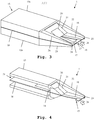
- a second embodiment of the over the air measurement module 1 is shown.
- the housing 15 comprises a first part 15a and a second part 15b.
- the two housing parts surround the substrate 18 and hold the substrate 18 between themselves.
- the substrate 18 comprises an opening 27 between the antenna elements 16 and 17. This opening 27 further reduces the influence of the substrate material on the received or transmitted signal.
- the embodiment shown here comprises a substrate bridge 28 connecting opposite parts of the tapered slot line antenna in the area of the antenna aperture.
- the over the air measurement module 1 comprises an absorber 20, which is arranged surrounding the substrate 18 at the narrow end of the tapered slot line antenna 19.
- the absorber 20 prevents reflections towards the device under test 2.
- the geometric shape of the over the air measurement module 1 is evident. Especially, it is evident here, that the over the air measurement module 1 is tapered towards the main radiation direction of the antenna 19. Moreover, it is evident that all surfaces of the over the air measurement module 1 facing the main radiation direction of the antenna 19 are angled away from a normal of the main radiation direction of the antenna 19. This leads to an especially low reflectivity for signals emitted by the device under test 2. Here, only the very small surfaces 23, 24 point towards the device under test. All other surfaces 21, 22, 25, 26 are angled away from the device under test.
- At least 50%, preferably at least 80%, most preferably all surfaces of the over the air measurement module facing the main radiation direction of the antenna are therefore angled away from a normal of the main radiation direction of the antenna by at least 30°, preferably by at least 45°, most preferably by at least 60°.
- the relative permittivity ⁇ r is low. Especially, it is lower than 4, preferably ⁇ r ⁇ 2, most preferably ⁇ r ⁇ 1.5. For the same reason, the relative permeability ⁇ r is low. Advantageously it is below 3, preferably ⁇ r ⁇ 2, most preferably ⁇ r ⁇ 1.5.
- Fig. 4 a cut open view of the embodiment of Fig. 3 is shown.
- the housing 15 comprises an opening 29, which encloses the substrate 18.
- the analog signal processor 14 Arranged on the substrate 18 is the analog signal processor 14, which is connected to the antenna element 16, 17 of the antenna 19.
- the analog signal processor 14 processes signals received by the antenna 19 and signals to be transmitted by the antenna 19.
- the analog signal processor 14 performs a frequency conversion.
- Fig. 4 Apart from Fig. 4 is that the absorber 20 surrounds the substrate 18 on both sides in order to reduce the reflections towards the device under test.
- the antenna 19 instead of forming the antenna 19 as depicted here, it is also possible to use two tapered slot line antennas on substrates, which are arranged orthogonally. In this case, a dual linear polarization measurement can be provided. The signals of these two antennas can be handled separately or can be combined.
- a power sensor can be integrated into the analog signal processor 14. A power measurement of signals received from the device under test can then be performed there. The power measurement in this case would be performed under a frequency reduced first measuring signal.
- a load resistor of the power sensor of the antenna has a higher value than 50 Ohm.
- a diode sensor produced in slot line technology can be used as a power sensor.
- a rectification and/or a bandwidth limitation and/or an analog-digital-conversion can also be integrated into the analog signal processor.
- the analog signal processor 14 can moreover be adapted to provide an intermediate frequency signal or a baseband signal to the connector 13.
- the over the air measurement module 1 is adapted to perform a wireless measurement.
- the connector 13 can be implemented as a wireless interface for wirelessly transmitting the measuring results to the measuring device 2.
- the measuring system 30 into an antenna module and a detector module.
- the antenna module would then comprise all aspects presently contained in the over the air measurement module, while the detector module would comprise at least a detector for determining certain aspects of the measured signal, for example the power of the signal.
- a sensor/processing module could be separately constructed.
- the over the air measurement module 1 could be split into an antenna module only comprising the antenna 19 and a processing module comprising the analog signal processor 14.
- the antenna module, processing module and detector module can be integrated into a single module or housing. Also they can be separately constructed. Especially, an integration of the detector module and the antenna module is possible.
- electrical conductors for example coplanar transmission lines can be used. Also the use of optical transmission lines is possible.
- a chopper can be integrated into the detector module. By repeatedly reversing the polarity of the measured signal, the influence of noise can be mitigated. Especially, the influence of accidently coupling noise signals can be reduced.
- the detector can be formed based on a coplanar transmission line. This allows for an easy transmission of the detected power to further components.
- the antenna signals especially if the antenna is a slot line antenna, can be converted to a signal on a coplanar transmission line so that they can be more easily handled on the circuit board and supplied to the further components.
- the change of the transmission typology from slot line to coplanar can be performed either between the antenna and the analog signal processor or between the analog signal processor and the connector.
- the invention is not limited to the examples and especially not to a specific measurement direction. Also the measured signals are not limited to a specific communications task.
Landscapes
- Physics & Mathematics (AREA)
- Electromagnetism (AREA)
- Engineering & Computer Science (AREA)
- Computer Networks & Wireless Communication (AREA)
- Signal Processing (AREA)
- General Physics & Mathematics (AREA)
- Quality & Reliability (AREA)
- Arrangements For Transmission Of Measured Signals (AREA)
- Variable-Direction Aerials And Aerial Arrays (AREA)
- Waveguide Aerials (AREA)
Description
- The invention relates to an over the air measurement module for measuring high frequency signals, especially communication signals over the air.
- During recent years, radio frequencies employed for performing communication tasks have continually risen. Especially with frequencies exceeding many GHz, new problems regarding the measurement of respective signals arise. By connecting the signal source to a measuring device using a cable connection, the behavior of the device under test is influenced.
- For example the document
US 2015/0035707 A1 shows a slot line antenna on a printed circuit board. The antenna shown there is capable of receiving high frequency signals. - Document
JP 2009 115644 A - There arises the object of providing measuring means for measuring high frequency signals with a high accuracy and a small size and hardware effort.
- The object is solved by the features of
claim 1 for the device. The dependent claims contain further developments. - According to a first implementation, an over the air measurement module is provided. The over the air measurement module comprises an antenna, which is adapted to receive a first measuring signal from a device under test. Moreover, it comprises an analog signal processor which is directly connected to said the antenna and is adapted to reduce a frequency of the received first measuring signal, resulting in a frequency reduced first measuring signal. Furthermore, the over the air measurement module comprises a connector, connected to said analog signal processor, which is adapted to output the first frequency reduced measuring signal. It is thereby possible to acquire a measuring signal of an extremely high frequency without altering it and to provide a lower frequency measuring signal to further measuring devices.
- Alternatively or additionally, the connector is adapted to receive a second frequency reduced measuring signal and provide it to the analog signal processor which is then adapted to increase a frequency of the frequency reduced second measuring signal, resulting in a second measuring signal. The antenna is then adapted to transmit this second measuring signal to the device under test. It is thereby possible to provide a measuring signal of extremely high frequency to the device under test in a controlled manner without influencing the measuring results.
- According to an implementation form of the first aspect, the antenna is a planar antenna. A main radiation direction of the antenna is in the plane of the planar antenna. It is thereby possible to achieve a very low size of the over the air measurement module.
- According to a further development of this implementation form, at least some surfaces, advantageously all surfaces of the measuring module facing in the main radiation direction of the antenna are adapted to absorb electromagnetic radiation and do not reflect electromagnetic radiation. Thereby, reflections towards the device under test are prevented. This increases the measuring accuracy.
- According to a further implementation form, at least some surfaces, advantageously all surfaces of the measuring device facing in the main radiation direction of the antenna are coated with a paint absorbing electromagnetic radiation and/or covered with absorber material absorbing electromagnetic radiation and/or fabricated from absorber material absorbing electromagnetic radiation. It is thereby possible to further reduce reflections towards the device under test thereby increasing the measuring accuracy.
- According to a further implementation form of the first aspect, at least 50% of all surfaces preferably at least 80% of all surfaces, most preferably all surfaces of the over the air measurement module facing the main radiation direction of the antenna are angled away from a normal of the main radiation direction of the antenna by at least 30°, preferably by at least 45°, most preferably by at least 60°. This further helps to reduce reflections towards the device under test, further increasing measuring accuracy.
- According to a further implementation form of the first aspect, the over the air measurement module is tapered towards the main radiation direction of the antenna. First of all, this measure also reduces reflections towards the device under test, thereby increasing measuring accuracy. Also, this measure allows for an especially small foot print of the over the air measurement module. This increases the flexibility of use.
- According to a further implementation form of the first aspect of the invention, if the antenna is adapted to receive the first measuring signal from the device under test, the analog signal processor is adapted to reduce the frequency of the received first measuring signal and the connector is adapted to output the first frequency reduced measuring signal, and the analog signal processor comprises a mixer, adapted to down-convert the first measuring signal to the frequency reduced first measuring signal. It is thereby possible to use regular measuring devices for measuring the frequency reduced first measuring signal without influencing the measuring result.
- According to a further development of the previous implementation form, the analog signal processor further comprises a filter, adapted to perform a filtering of the first measuring signal and/or of the first frequency reduced measuring signal. Alternatively or additionally, the analog signal processor comprises a power sensor, adapted to measure the power of the first frequency reduced measuring signal. Alternatively or additionally, the analog signal processor comprises an amplifier, adapted to amplify the first measuring signal and/or the first frequency reduced measuring signal. Additionally or alternatively, the analog signal processor furthermore comprises a radio frequency switch, adapted to switch between different operating modes of the over the air measurement module. It is thereby possible to flexibly perform a post processing of the first measuring signal and signals derived therefrom.
- According to a further implementation form of the first aspect, if the connector is adapted to receive the second frequency reduced measuring signal, and the analog signal processor is adapted to increase the frequency of the frequency reduced second measuring signal, and the antenna is adapted to transmit the second measuring signal to the device under test, and the analog signal processor comprises a mixer, adapted to up-convert the frequency reduced second measuring signal to the second measuring signal. It is thereby possible to generate the frequency reduced second measuring signal by for example a regular signal generator and to provide the second measuring signal of an extremely high frequency to the device under test.
- According to a further development of the previous implementation form, the analog signal processor further comprises a filter, adapted to perform a filtering of the second measuring signal and/or the second frequency reduced measuring signal. Alternatively or additionally, the analog signal processor comprises an amplifier, adapted to amplify the second measuring signal and/or the second frequency reduced measuring signal. Moreover, alternatively or additionally, the analog signal processor comprises a radio frequency switch, adapted to switch between different operating modes of the over the air measurement module. It is thereby possible to flexibly perform a pre-processing of the second measuring signal before handing it to the device under test.
- According to a further implementation form of the first aspect, the over the air measurement module comprises a substrate, advantageously a printed circuit board. The antenna and the analog signal processor are arranged on the substrate. The antenna is planar with the substrate. The main radiation direction of the antenna is towards an edge of the substrate. It is thereby possible to achieve an extremely small size and low footprint of the over the air measurement module.
- According to a further development of the previous implementation form, the substrate has a relative permittivity εr of εr<4, preferably εr<2, most preferably εr<1.5. Additionally or alternatively, the substrate has a relative permeability µr of µr<3, preferably µr<2, most preferably µr<1.5. A very low influence of the substrate on the measuring signal is thereby achieved.
- According to a further development of the previous two implementation forms, the antenna is a tapered slot line antenna, advantageously a Vivaldi antenna. It is thereby possible, to achieve satisfactory high frequency characteristics, while achieving a very small size of the antenna.
- According to a further development form of the previous implementation form, the substrate comprises an opening between conductors of the tapered slot line antenna. Additionally or alternatively, a substrate bridge connects opposite parts of the tapered slot line antenna in an area of an antenna aperture. A very stable construction of the antenna with beneficial radio frequency characteristics is thereby achieved.
- According to a second aspect of the invention, a measuring system comprising a previously described over the air measurement module is provided. The measuring system comprises a measuring device. The measuring device is adapted to receive and measure the frequency reduced first measuring signal from the over the air measurement module. Alternatively or additionally, the measuring device is adapted to provide the frequency reduced second measuring signal to the over the air measurement module. A very flexible and accurate measurement is thereby possible.
- Exemplary embodiments of the invention are now further explained with respect to the drawings, by way of example only. The invention is, however, not limited to these embodiments. In the drawings:
- Fig. 1
- shows a system with a first embodiment of the over the air measurement module and a measuring device of the invention in a top-down view;
- Fig. 2
- shows the first embodiment of the over the air measurement module of the invention in a side-view;
- Fig. 3
- shows a second embodiment of the over the air measurement module of the invention in a three-dimensional view; and
- Fig. 4
- shows the second embodiment of the over the air measurement module of the invention in a cut-view.
- First we demonstrate the general construction and function of an over the air measurement module along
Fig. 1 and Fig. 2 . AlongFig. 3 and Fig. 4 further details of another implementation form are described. Similar entities and reference numbers in different figures have been partially omitted. - In
Fig. 1 , a first embodiment of the over theair measurement module 1 according to the first aspect of the invention is shown. The over theair measurement module 1 comprises ahousing 15 which contains asubstrate 18, advantageously a printed circuit board. On thesubstrate 18, twoantenna elements slot line antenna 19, are arranged. Theantenna 19 is connected to ananalog signal processor 14 which is also arranged on thesubstrate 18. The analog signal processor moreover is connected to aconnector 13 which serves as aninterface 13. Connectable to theinterface 13 is a measuringdevice 2, which is not part of the over theair measurement module 1. Theantenna 19 has a main radiation direction towards the right edge of thesubstrate 18, indicated by an arrow in the figures. A device undertest 3 is suitably arranged in this direction. - In order to minimize reflections from the over the
air measurement module 1, thehousing 15 is tapered towards the main radiation direction of theantenna 19. This tapering reduces the effective surface area, which can produce reflections. In order to further reduce such reflections, thehousing 15 can be fabricated from an electromagnetic radiation absorbing material. It can also be covered with such a material or can be coated with an absorptive paint. Thehousing 15 furthermore comprises aback plate 11, which is covered withabsorptive material 12 in order to further reduce reflections. - The over the
air measurement module 1 is suitable for two types of measurements. In a first type of measurement, a first measuring signal emitted from the device undertest 3 is received by theantenna 19 and handed to theanalog signal processor 14. Theanalog signal processor 14 reduces the frequency of the first measuring signal resulting in a frequency reduced first measuring signal. - This is for example done by down-converting the first measuring signal using a mixer. Additionally, the analog signal processor in this case can comprise one or more filters for filtering the first measuring signal or the frequency reduced first measuring signal, a power sensor, which can be used for directly measuring a power of the frequency reduced first measuring signal, an amplifier for amplifying the first measuring signal or the first frequency reduced measuring signal, and a radio frequency switch for switching between the previously described measuring option and the measuring option described in the following. The processed frequency reduced measuring signal is then handed on to the
connector 13, which passes on the signal to for example anexternal measuring device 2 for further processing the frequency reduced measuring signal. - Alternatively, the over the air measurement module can be used for another type of measurement. In this case, the
connector 13 receives a frequency reduced second measuring signal from the measuringdevice 2. It is handed on to theanalog signal processor 14. Theanalog signal processor 14 increases the frequency of the frequency reduced second measuring signal resulting in a second measuring signal. This is for example done by mixing the frequency reduced second measuring signal with a further local oscillator signal. The second measuring signal is then transmitted by theantenna 19 to the device undertest 3. Also, in this case, the analog signal processor can comprise additional components. The analog signal processor can comprise a filter, for filtering the second measuring signal and/or the second frequency reduced measuring signal. Also, the analog signal processor can comprise an amplifier for amplifying the second measuring signal and/or the second frequency reduced measuring signal. Moreover, the analog signal processor can comprise a radio frequency switch, adapted to switch between different operating modes of the over the air measurement module. - Also here, the
measurement system 30 according to the second aspect of the invention is depicted. The measuringsystem 30 comprises the over theair measurement module 1 and the measuringdevice 2. The measuringdevice 2 is adapted to receive and measure the frequency reduced first measuring signal and/or to provide the frequency reduced second measuring signal to be transmitted to the device undertest 3 as second measuring signal. - In
Fig. 2 the over the air measurement module ofFig. 1 is shown in a cut view from the side. Here it can be seen that theanalog signal processor 14 and theconnector 13 are arranged on thesubstrate 18. Moreover, the tapering of thehousing 15 and the arrangement of theabsorbers 12 can be seen. - In
Fig. 3 a second embodiment of the over theair measurement module 1 is shown. Here, a three-dimensional view of the over theair measurement module 1 is depicted. Thehousing 15 comprises afirst part 15a and asecond part 15b. The two housing parts surround thesubstrate 18 and hold thesubstrate 18 between themselves. Thesubstrate 18 comprises anopening 27 between theantenna elements opening 27 further reduces the influence of the substrate material on the received or transmitted signal. For reasons of stability, the embodiment shown here comprises asubstrate bridge 28 connecting opposite parts of the tapered slot line antenna in the area of the antenna aperture. - Moreover, the over the
air measurement module 1 comprises anabsorber 20, which is arranged surrounding thesubstrate 18 at the narrow end of the taperedslot line antenna 19. Theabsorber 20 prevents reflections towards the device undertest 2. - Moreover, in this embodiment, the geometric shape of the over the
air measurement module 1 is evident. Especially, it is evident here, that the over theair measurement module 1 is tapered towards the main radiation direction of theantenna 19. Moreover, it is evident that all surfaces of the over theair measurement module 1 facing the main radiation direction of theantenna 19 are angled away from a normal of the main radiation direction of theantenna 19. This leads to an especially low reflectivity for signals emitted by the device undertest 2. Here, only the verysmall surfaces other surfaces - Especially, at least 50%, preferably at least 80%, most preferably all surfaces of the over the air measurement module facing the main radiation direction of the antenna are therefore angled away from a normal of the main radiation direction of the antenna by at least 30°, preferably by at least 45°, most preferably by at least 60°.
- In order to further reduce the effect of the
substrate 18 on the received or transmitted signal, the relative permittivity εr is low. Especially, it is lower than 4, preferably εr<2, most preferably εr<1.5. For the same reason, the relative permeability µr is low. Advantageously it is below 3, preferably µr<2, most preferably µr<1.5. - In
Fig. 4 a cut open view of the embodiment ofFig. 3 is shown. Here it is evident that thehousing 15 comprises anopening 29, which encloses thesubstrate 18. Arranged on thesubstrate 18 is theanalog signal processor 14, which is connected to theantenna element antenna 19. As explained earlier, theanalog signal processor 14 processes signals received by theantenna 19 and signals to be transmitted by theantenna 19. Especially theanalog signal processor 14 performs a frequency conversion. - Evident from
Fig. 4 is that theabsorber 20 surrounds thesubstrate 18 on both sides in order to reduce the reflections towards the device under test. - Instead of forming the
antenna 19 as depicted here, it is also possible to use two tapered slot line antennas on substrates, which are arranged orthogonally. In this case, a dual linear polarization measurement can be provided. The signals of these two antennas can be handled separately or can be combined. - Also advantageously, a power sensor can be integrated into the
analog signal processor 14. A power measurement of signals received from the device under test can then be performed there. The power measurement in this case would be performed under a frequency reduced first measuring signal. In this case, a load resistor of the power sensor of the antenna has a higher value than 50 Ohm. - As a power sensor, a diode sensor produced in slot line technology can be used.
- In addition, a rectification and/or a bandwidth limitation and/or an analog-digital-conversion can also be integrated into the analog signal processor. The
analog signal processor 14 can moreover be adapted to provide an intermediate frequency signal or a baseband signal to theconnector 13. - Advantageously, the over the
air measurement module 1 is adapted to perform a wireless measurement. This means that theconnector 13 can be implemented as a wireless interface for wirelessly transmitting the measuring results to themeasuring device 2. - Especially, it is possible to split the measuring
system 30 into an antenna module and a detector module. The antenna module would then comprise all aspects presently contained in the over the air measurement module, while the detector module would comprise at least a detector for determining certain aspects of the measured signal, for example the power of the signal. Moreover, a sensor/processing module could be separately constructed. In this case, the over theair measurement module 1 could be split into an antenna module only comprising theantenna 19 and a processing module comprising theanalog signal processor 14. The antenna module, processing module and detector module can be integrated into a single module or housing. Also they can be separately constructed. Especially, an integration of the detector module and the antenna module is possible. - In order to connect the different modules, especially the sensor module, the antenna module, the detector module and the processing module, electrical conductors, for example coplanar transmission lines can be used. Also the use of optical transmission lines is possible.
- In order to minimize noise, a chopper can be integrated into the detector module. By repeatedly reversing the polarity of the measured signal, the influence of noise can be mitigated. Especially, the influence of accidently coupling noise signals can be reduced.
- Advantageously, the detector can be formed based on a coplanar transmission line. This allows for an easy transmission of the detected power to further components. Advantageously, the antenna signals, especially if the antenna is a slot line antenna, can be converted to a signal on a coplanar transmission line so that they can be more easily handled on the circuit board and supplied to the further components.
- The change of the transmission typology from slot line to coplanar can be performed either between the antenna and the analog signal processor or between the analog signal processor and the connector.
- The invention is not limited to the examples and especially not to a specific measurement direction. Also the measured signals are not limited to a specific communications task.
Claims (14)
- An over the air measurement module (1), comprising:- an antenna (19), adapted to receive a first measuring signal from a device under test (3) and/or adapted to transmit a second measuring signal to the device under test (3),- a analog signal processor (14), directly connected to said antenna (19), adapted to reduce a frequency of the received first measuring signal, resulting in a frequency reduced first measuring signal, and/or adapted to increase a frequency of a frequency reduced second measuring signal, resulting in the second measuring signal, and- a connector (13), connected to said analog signal processor (14), adapted to output the first frequency reduced measuring signal, and/or adapted to receive the second frequency reduced measuring signal, the over the air measurement module (1) is characterised in that the antenna (19) is a planar antenna (19), and wherein a main radiation direction of the antenna (19) is in the plane of the planar antenna (19), and wherein at least 50% of the surfaces (21, 22, 25, 26) of the over the air measurement module (1) facing the main radiation direction of the antenna (19) are angled away from a normal of the main radiation direction of the antenna (19) by at least 30°.
- The over the air measurement module according to claim 1,
wherein at least some surfaces (21, 22, 23, 24, 25, 26), of the over the air measuring module (1) facing in the main radiation direction of the antenna (19) are adapted to absorb electromagnetic radiation and not reflect electromagnetic radiation. - The over the air measurement module according to claim 2,
wherein at least some surfaces (21, 22, 23, 24, 25, 26) of the over the air measuring module (1) facing in the main radiation direction of the antenna (19) are coated with a paint absorbing electromagnetic radiation and/or covered with absorber material absorbing electromagnetic radiation and/or fabricated from absorber material absorbing electromagnetic radiation. - The over the air measurement module according to any of the claims 2 to 3,
wherein at least 80%, most preferably all surfaces (21, 22, 25, 26) of the over the air measurement module (1) facing the main radiation direction of the antenna (19) are angled away from a normal of the main radiation direction of the antenna (19) by at least 45°, most preferably by at least 60°. - The over the air measurement module according to any of the claims 2 to 4,
wherein over the air measurement module (1) is tapered towards the main radiation direction of the antenna (19). - The over the air measurement module according to any of the claims 1 to 5,
wherein, if the antenna (19) is adapted to receive the first measuring signal from the device under test,
the analog signal processor (14) is adapted to reduce the frequency of the received first measuring signal, and
the connector (13) is adapted to output the first frequency reduced measuring signal, and the analog signal processor (14) comprises a mixer, adapted to down convert the first measuring signal to the frequency reduced first measuring signal. - The over the air measurement module according to claim 6,
wherein the analog signal processor (14) further comprises:- a filter, adapted to perform a filtering of the first measuring signal and/or of the first frequency reduced measuring signal, and/or- a power sensor, adapted to measure the power of the first frequency reduced measuring signal, and/or- an amplifier, adapted to amplify the first measuring signal and/or the first frequency reduced measuring signal, and/or- a radio frequency switch, adapted to switch between different operating modes of the over the air measurement module (1). - The over the air measurement module according to any of the claims 1 to 7,
wherein, if the connector (13) is adapted to receive the second frequency reduced measuring signal,
the analog signal processor (14) is adapted to increase the frequency of the frequency reduced second measuring signal,
the antenna (19) is adapted to transmit the second measuring signal to the device under test, and
the analog signal processor (14) comprises a mixer, adapted to up convert the frequency reduced second measuring signal to the second measuring signal. - The over the air measurement module according to claim 8,
wherein the analog signal processor (14) further comprises:- a filter, adapted to perform a filtering of the second measuring signal and/or the second frequency reduced measuring signal, and/or- an amplifier, adapted to amplify the second measuring signal and/or the second frequency reduced measuring signal, and/or- a radio frequency switch, adapted to switch between different operating modes of the over the air measurement module (1). - The over the air measurement module according to any of the claims 1 to 9,
wherein over the air measurement module (1) comprises a substrate (18), advantageously a printed circuit board (18),
wherein the antenna (19) and the analog signal processor (14) are arranged on the substrate (18),
wherein the antenna (19) is planar with the substrate (18), and
wherein the main radiation direction of the antenna (19) is towards an edge of the substrate. - The over the air measurement module according to claim 10,
wherein the substrate (18) has a relative permittivity εr of εr < 4, preferably εr < 2, most preferably εr < 1.5, and/or
wherein the substrate (18) has a relative permeability µr of µr < 3, preferably µr < 2, most preferably µr < 1.5. - The over the air measurement module according to claim 10 or 11,
wherein the antenna (19) is a tapered slotline antenna (19), preferably a Vivaldi antenna (19). - The over the air measurement module according to claim 12,
wherein the substrate (18) comprises an opening (27) between conductors of the tapered slotline antenna (19), and/or
wherein a substrate bridge (28) connects opposite parts of the tapered slotline antenna (19) in an area of an antenna aperture. - Measuring system comprising an over the air measurement module (1) according to any of the claims 1 to 13 and a measuring device (2),
wherein the measuring device (2) is adapted to receive and measure the frequency reduced first measuring signal from the over the air measurement module (1) and/or is adapted to provide the frequency reduced second measuring signal to the over the air measurement module (1).
Priority Applications (6)
| Application Number | Priority Date | Filing Date | Title |
|---|---|---|---|
| EP16153360.9A EP3199957B1 (en) | 2016-01-29 | 2016-01-29 | Over the air measurement module |
| US15/175,197 US10200135B2 (en) | 2016-01-29 | 2016-06-07 | Over the air measurement module |
| EP16179629.7A EP3199958B8 (en) | 2016-01-29 | 2016-07-15 | Apparatus and method for testing beamforming behavior |
| US15/296,407 US10193639B2 (en) | 2016-01-29 | 2016-10-18 | Over the air measurement module |
| CN201610921861.2A CN107026697B (en) | 2016-01-29 | 2016-10-21 | Apparatus and method for testing beamforming behavior |
| US15/363,521 US10411813B2 (en) | 2016-01-29 | 2016-11-29 | Apparatus and method for testing beamforming behavior |
Applications Claiming Priority (1)
| Application Number | Priority Date | Filing Date | Title |
|---|---|---|---|
| EP16153360.9A EP3199957B1 (en) | 2016-01-29 | 2016-01-29 | Over the air measurement module |
Publications (2)
| Publication Number | Publication Date |
|---|---|
| EP3199957A1 EP3199957A1 (en) | 2017-08-02 |
| EP3199957B1 true EP3199957B1 (en) | 2020-12-30 |
Family
ID=55304848
Family Applications (2)
| Application Number | Title | Priority Date | Filing Date |
|---|---|---|---|
| EP16153360.9A Not-in-force EP3199957B1 (en) | 2016-01-29 | 2016-01-29 | Over the air measurement module |
| EP16179629.7A Active EP3199958B8 (en) | 2016-01-29 | 2016-07-15 | Apparatus and method for testing beamforming behavior |
Family Applications After (1)
| Application Number | Title | Priority Date | Filing Date |
|---|---|---|---|
| EP16179629.7A Active EP3199958B8 (en) | 2016-01-29 | 2016-07-15 | Apparatus and method for testing beamforming behavior |
Country Status (3)
| Country | Link |
|---|---|
| US (2) | US10200135B2 (en) |
| EP (2) | EP3199957B1 (en) |
| CN (1) | CN107026697B (en) |
Families Citing this family (9)
| Publication number | Priority date | Publication date | Assignee | Title |
|---|---|---|---|---|
| EP3264641B1 (en) * | 2016-06-29 | 2020-01-08 | Rohde & Schwarz GmbH & Co. KG | Over the air power sensor and method |
| KR102293662B1 (en) | 2017-09-27 | 2021-08-25 | 삼성전자 주식회사 | Test device of beam forming processor |
| EP3483615A1 (en) | 2017-11-10 | 2019-05-15 | Rohde & Schwarz GmbH & Co. KG | Measuring system and measuring method for over the air measurement of electric field potential |
| US10782331B2 (en) * | 2018-06-21 | 2020-09-22 | Rohde & Schwarz Gmbh & Co. Kg | Power measurement apparatus |
| EP3644072B8 (en) * | 2018-10-26 | 2022-08-31 | Rohde & Schwarz GmbH & Co. KG | Over-the-air measurement chamber and over-the-air measurement method |
| WO2020153221A1 (en) * | 2019-01-21 | 2020-07-30 | 日本電気株式会社 | Wireless communication quality visualization system, wireless communication quality visualization device, and measurement apparatus |
| CN109782077A (en) * | 2019-01-29 | 2019-05-21 | 西安天伟电子系统工程有限公司 | Wave beam test macro and method |
| CN113491076B (en) | 2019-02-19 | 2024-01-09 | 西门子工业软件有限公司 | Radio equipment test equipment |
| US12355506B2 (en) * | 2021-10-22 | 2025-07-08 | Hughes Network Systems, Llc | Techniques for calibration and measurements of an E-band satellite communication (SATCOM) system |
Family Cites Families (14)
| Publication number | Priority date | Publication date | Assignee | Title |
|---|---|---|---|---|
| FR2795522B1 (en) * | 1999-06-23 | 2001-08-10 | Agence Spatiale Europeenne | DEVICE FOR MEASURING CHARACTERISTICS OF AN ELECTROMAGNETIC FIELD, IN PARTICULAR THE RADIATION DIAGRAM OF AN ANTENNA |
| WO2005064747A1 (en) * | 2003-12-30 | 2005-07-14 | Telefonaktiebolaget Lm Ericsson (Publ) | Antenna device, and array antenna, with planar notch element feed |
| CN101019033A (en) * | 2005-01-11 | 2007-08-15 | 太阳诱电株式会社 | Electromagnetic field distribution measuring method and apparatus thereof, computer program and information recording medium |
| JP2009115644A (en) * | 2007-11-07 | 2009-05-28 | Ntt Docomo Inc | Electric field probe, electric field measuring device |
| US9847843B2 (en) * | 2009-08-28 | 2017-12-19 | Advantest Corporation | Apparatus and method for wireless testing of a plurality of transmit paths and a plurality of receive paths of an electronic device |
| FR2978249B1 (en) * | 2011-07-22 | 2013-07-26 | Thales Sa | CALIBRATION AND TEST DEVICE FOR AN ACTIVE ANTENNA, IN PARTICULAR AN ADVANCED ANTENNA FOR AN AIRBORNE RADAR |
| FR2976146A1 (en) * | 2011-12-22 | 2012-12-07 | Thomson Licensing | Test card for testing printed circuit board utilized in e.g. wireless system, has supply line connected to conductive area of substrate for creating electromagnetic coupling type line/slot at antenna of printed circuit board |
| TWI456215B (en) * | 2012-01-09 | 2014-10-11 | Wistron Neweb Corp | Test equipment for wireless electronic devices |
| US9322864B2 (en) * | 2012-10-01 | 2016-04-26 | Ets-Lindgren, Lp | Methods and apparatus for evaluating radiated performance of MIMO wireless devices in three dimensions |
| CN103780291B (en) * | 2012-10-25 | 2017-04-19 | 华为技术有限公司 | Method, device and base station by using three-dimensional beam codebooks to perform communication |
| CN103856272B (en) | 2012-12-03 | 2017-09-05 | 深圳市通用测试系统有限公司 | The wireless performance method of testing of MIMO wireless terminals |
| WO2014105787A1 (en) | 2012-12-27 | 2014-07-03 | Zte (Usa) Inc. | Method and system for ue measurements in support of mimo ota |
| US9941982B2 (en) * | 2013-04-10 | 2018-04-10 | Marvell World Trade Ltd. | Method and apparatus for testing the beamforming performance of a wireless communication device |
| US9606158B2 (en) | 2013-08-02 | 2017-03-28 | Rohde & Schwarz Gmbh & Co. Kg | Slotline antenna |
-
2016
- 2016-01-29 EP EP16153360.9A patent/EP3199957B1/en not_active Not-in-force
- 2016-06-07 US US15/175,197 patent/US10200135B2/en active Active
- 2016-07-15 EP EP16179629.7A patent/EP3199958B8/en active Active
- 2016-10-21 CN CN201610921861.2A patent/CN107026697B/en active Active
- 2016-11-29 US US15/363,521 patent/US10411813B2/en active Active
Non-Patent Citations (1)
| Title |
|---|
| None * |
Also Published As
| Publication number | Publication date |
|---|---|
| US20170222736A1 (en) | 2017-08-03 |
| EP3199958A1 (en) | 2017-08-02 |
| CN107026697B (en) | 2021-06-25 |
| US20170222734A1 (en) | 2017-08-03 |
| US10411813B2 (en) | 2019-09-10 |
| EP3199958B8 (en) | 2020-07-15 |
| EP3199957A1 (en) | 2017-08-02 |
| EP3199958B1 (en) | 2020-05-27 |
| US10200135B2 (en) | 2019-02-05 |
| CN107026697A (en) | 2017-08-08 |
Similar Documents
| Publication | Publication Date | Title |
|---|---|---|
| EP3199957B1 (en) | Over the air measurement module | |
| US8897717B2 (en) | Dual-feed antenna array with integral comparison circuit for phase and amplitude calibration | |
| Gulan et al. | Probe based antenna measurements up to 325 GHz for upcoming millimeter-wave applications | |
| JP2003525455A (en) | Method and apparatus for measuring true transmitted power using a broadband dual directional coupler | |
| CN107547152B (en) | Over-the-air transmission power detector and method | |
| US10693572B2 (en) | Measuring system for over-the-air power measurements with active transmission | |
| US20260051926A1 (en) | High-performance probe for near-field antenna measurement | |
| Girma et al. | 122 GHz radar sensor based on a monostatic SiGe-BiCMOS IC with an on-chip antenna | |
| Hitzler et al. | Design and characterization concepts of a broadband chip-integrated antenna | |
| CN115524694B (en) | A multi-input multi-output high-isolation continuous wave radar antenna system | |
| US10193639B2 (en) | Over the air measurement module | |
| KR101025910B1 (en) | Patch Antenna for Wideband Phased Array | |
| US11984636B2 (en) | Active waveguide transition having a probe and RF amplifier system and which is usable in a transmit/receive communication system | |
| US20050264469A1 (en) | Antenna coupler | |
| CN214378841U (en) | High-precision four-feed laminated vehicle-mounted external ceramic active antenna | |
| Reniers et al. | Guidelines for millimeter-wave antenna measurements | |
| CN210576425U (en) | UWB antenna device | |
| CN209894970U (en) | Miniaturized range finding subassembly | |
| KR101291274B1 (en) | Mobile communication terminal and antenna thereof | |
| KR102495673B1 (en) | Signal processing or generating device, and method for determining adjustment | |
| Reher et al. | Spectrum-Analyzer-Based Radar System Measurements in a Compact Antenna Test Range | |
| US20170201334A1 (en) | Direct Measurement of Reflected Waves of Multi-Port Antennas by Using Circulators | |
| Girma | Concepts for Short Range Millimeter-wave Miniaturized Radar Systems with Built-in Self-Test | |
| Liu | IC-Antenna Co-Integration for Efficient and Scalable Millimeter-Wave Antenna Interfaces | |
| JP2016161525A (en) | Speed measuring device |
Legal Events
| Date | Code | Title | Description |
|---|---|---|---|
| PUAI | Public reference made under article 153(3) epc to a published international application that has entered the european phase |
Free format text: ORIGINAL CODE: 0009012 |
|
| STAA | Information on the status of an ep patent application or granted ep patent |
Free format text: STATUS: REQUEST FOR EXAMINATION WAS MADE |
|
| 17P | Request for examination filed |
Effective date: 20160909 |
|
| AK | Designated contracting states |
Kind code of ref document: A1 Designated state(s): AL AT BE BG CH CY CZ DE DK EE ES FI FR GB GR HR HU IE IS IT LI LT LU LV MC MK MT NL NO PL PT RO RS SE SI SK SM TR |
|
| AX | Request for extension of the european patent |
Extension state: BA ME |
|
| STAA | Information on the status of an ep patent application or granted ep patent |
Free format text: STATUS: EXAMINATION IS IN PROGRESS |
|
| 17Q | First examination report despatched |
Effective date: 20190225 |
|
| REG | Reference to a national code |
Ref country code: DE Ref legal event code: R079 Ref document number: 602016050465 Country of ref document: DE Free format text: PREVIOUS MAIN CLASS: G01R0029080000 Ipc: G01R0029100000 |
|
| GRAP | Despatch of communication of intention to grant a patent |
Free format text: ORIGINAL CODE: EPIDOSNIGR1 |
|
| STAA | Information on the status of an ep patent application or granted ep patent |
Free format text: STATUS: GRANT OF PATENT IS INTENDED |
|
| RIC1 | Information provided on ipc code assigned before grant |
Ipc: G01R 29/10 20060101AFI20200904BHEP Ipc: H01Q 13/08 20060101ALI20200904BHEP Ipc: H04B 17/29 20150101ALI20200904BHEP Ipc: G01R 31/28 20060101ALI20200904BHEP Ipc: G01R 29/08 20060101ALI20200904BHEP Ipc: H04B 17/15 20150101ALI20200904BHEP Ipc: H04B 17/00 20150101ALI20200904BHEP Ipc: H01Q 17/00 20060101ALI20200904BHEP Ipc: H04B 17/10 20150101ALI20200904BHEP |
|
| INTG | Intention to grant announced |
Effective date: 20200930 |
|
| GRAS | Grant fee paid |
Free format text: ORIGINAL CODE: EPIDOSNIGR3 |
|
| GRAA | (expected) grant |
Free format text: ORIGINAL CODE: 0009210 |
|
| STAA | Information on the status of an ep patent application or granted ep patent |
Free format text: STATUS: THE PATENT HAS BEEN GRANTED |
|
| AK | Designated contracting states |
Kind code of ref document: B1 Designated state(s): AL AT BE BG CH CY CZ DE DK EE ES FI FR GB GR HR HU IE IS IT LI LT LU LV MC MK MT NL NO PL PT RO RS SE SI SK SM TR |
|
| REG | Reference to a national code |
Ref country code: GB Ref legal event code: FG4D |
|
| REG | Reference to a national code |
Ref country code: AT Ref legal event code: REF Ref document number: 1350455 Country of ref document: AT Kind code of ref document: T Effective date: 20210115 |
|
| REG | Reference to a national code |
Ref country code: DE Ref legal event code: R096 Ref document number: 602016050465 Country of ref document: DE |
|
| REG | Reference to a national code |
Ref country code: IE Ref legal event code: FG4D |
|
| PG25 | Lapsed in a contracting state [announced via postgrant information from national office to epo] |
Ref country code: NO Free format text: LAPSE BECAUSE OF FAILURE TO SUBMIT A TRANSLATION OF THE DESCRIPTION OR TO PAY THE FEE WITHIN THE PRESCRIBED TIME-LIMIT Effective date: 20210330 Ref country code: RS Free format text: LAPSE BECAUSE OF FAILURE TO SUBMIT A TRANSLATION OF THE DESCRIPTION OR TO PAY THE FEE WITHIN THE PRESCRIBED TIME-LIMIT Effective date: 20201230 Ref country code: FI Free format text: LAPSE BECAUSE OF FAILURE TO SUBMIT A TRANSLATION OF THE DESCRIPTION OR TO PAY THE FEE WITHIN THE PRESCRIBED TIME-LIMIT Effective date: 20201230 Ref country code: GR Free format text: LAPSE BECAUSE OF FAILURE TO SUBMIT A TRANSLATION OF THE DESCRIPTION OR TO PAY THE FEE WITHIN THE PRESCRIBED TIME-LIMIT Effective date: 20210331 |
|
| REG | Reference to a national code |
Ref country code: AT Ref legal event code: MK05 Ref document number: 1350455 Country of ref document: AT Kind code of ref document: T Effective date: 20201230 |
|
| PG25 | Lapsed in a contracting state [announced via postgrant information from national office to epo] |
Ref country code: BG Free format text: LAPSE BECAUSE OF FAILURE TO SUBMIT A TRANSLATION OF THE DESCRIPTION OR TO PAY THE FEE WITHIN THE PRESCRIBED TIME-LIMIT Effective date: 20210330 Ref country code: LV Free format text: LAPSE BECAUSE OF FAILURE TO SUBMIT A TRANSLATION OF THE DESCRIPTION OR TO PAY THE FEE WITHIN THE PRESCRIBED TIME-LIMIT Effective date: 20201230 Ref country code: SE Free format text: LAPSE BECAUSE OF FAILURE TO SUBMIT A TRANSLATION OF THE DESCRIPTION OR TO PAY THE FEE WITHIN THE PRESCRIBED TIME-LIMIT Effective date: 20201230 |
|
| REG | Reference to a national code |
Ref country code: NL Ref legal event code: MP Effective date: 20201230 |
|
| PG25 | Lapsed in a contracting state [announced via postgrant information from national office to epo] |
Ref country code: HR Free format text: LAPSE BECAUSE OF FAILURE TO SUBMIT A TRANSLATION OF THE DESCRIPTION OR TO PAY THE FEE WITHIN THE PRESCRIBED TIME-LIMIT Effective date: 20201230 |
|
| REG | Reference to a national code |
Ref country code: LT Ref legal event code: MG9D |
|
| PG25 | Lapsed in a contracting state [announced via postgrant information from national office to epo] |
Ref country code: RO Free format text: LAPSE BECAUSE OF FAILURE TO SUBMIT A TRANSLATION OF THE DESCRIPTION OR TO PAY THE FEE WITHIN THE PRESCRIBED TIME-LIMIT Effective date: 20201230 Ref country code: PT Free format text: LAPSE BECAUSE OF FAILURE TO SUBMIT A TRANSLATION OF THE DESCRIPTION OR TO PAY THE FEE WITHIN THE PRESCRIBED TIME-LIMIT Effective date: 20210430 Ref country code: SK Free format text: LAPSE BECAUSE OF FAILURE TO SUBMIT A TRANSLATION OF THE DESCRIPTION OR TO PAY THE FEE WITHIN THE PRESCRIBED TIME-LIMIT Effective date: 20201230 Ref country code: CZ Free format text: LAPSE BECAUSE OF FAILURE TO SUBMIT A TRANSLATION OF THE DESCRIPTION OR TO PAY THE FEE WITHIN THE PRESCRIBED TIME-LIMIT Effective date: 20201230 Ref country code: EE Free format text: LAPSE BECAUSE OF FAILURE TO SUBMIT A TRANSLATION OF THE DESCRIPTION OR TO PAY THE FEE WITHIN THE PRESCRIBED TIME-LIMIT Effective date: 20201230 Ref country code: LT Free format text: LAPSE BECAUSE OF FAILURE TO SUBMIT A TRANSLATION OF THE DESCRIPTION OR TO PAY THE FEE WITHIN THE PRESCRIBED TIME-LIMIT Effective date: 20201230 |
|
| PG25 | Lapsed in a contracting state [announced via postgrant information from national office to epo] |
Ref country code: AT Free format text: LAPSE BECAUSE OF FAILURE TO SUBMIT A TRANSLATION OF THE DESCRIPTION OR TO PAY THE FEE WITHIN THE PRESCRIBED TIME-LIMIT Effective date: 20201230 Ref country code: PL Free format text: LAPSE BECAUSE OF FAILURE TO SUBMIT A TRANSLATION OF THE DESCRIPTION OR TO PAY THE FEE WITHIN THE PRESCRIBED TIME-LIMIT Effective date: 20201230 |
|
| REG | Reference to a national code |
Ref country code: CH Ref legal event code: PL |
|
| PG25 | Lapsed in a contracting state [announced via postgrant information from national office to epo] |
Ref country code: IS Free format text: LAPSE BECAUSE OF FAILURE TO SUBMIT A TRANSLATION OF THE DESCRIPTION OR TO PAY THE FEE WITHIN THE PRESCRIBED TIME-LIMIT Effective date: 20210430 Ref country code: LU Free format text: LAPSE BECAUSE OF NON-PAYMENT OF DUE FEES Effective date: 20210129 |
|
| REG | Reference to a national code |
Ref country code: DE Ref legal event code: R097 Ref document number: 602016050465 Country of ref document: DE |
|
| REG | Reference to a national code |
Ref country code: BE Ref legal event code: MM Effective date: 20210131 |
|
| PG25 | Lapsed in a contracting state [announced via postgrant information from national office to epo] |
Ref country code: MC Free format text: LAPSE BECAUSE OF FAILURE TO SUBMIT A TRANSLATION OF THE DESCRIPTION OR TO PAY THE FEE WITHIN THE PRESCRIBED TIME-LIMIT Effective date: 20201230 Ref country code: IT Free format text: LAPSE BECAUSE OF FAILURE TO SUBMIT A TRANSLATION OF THE DESCRIPTION OR TO PAY THE FEE WITHIN THE PRESCRIBED TIME-LIMIT Effective date: 20201230 Ref country code: AL Free format text: LAPSE BECAUSE OF FAILURE TO SUBMIT A TRANSLATION OF THE DESCRIPTION OR TO PAY THE FEE WITHIN THE PRESCRIBED TIME-LIMIT Effective date: 20201230 |
|
| PLBE | No opposition filed within time limit |
Free format text: ORIGINAL CODE: 0009261 |
|
| STAA | Information on the status of an ep patent application or granted ep patent |
Free format text: STATUS: NO OPPOSITION FILED WITHIN TIME LIMIT |
|
| PG25 | Lapsed in a contracting state [announced via postgrant information from national office to epo] |
Ref country code: LI Free format text: LAPSE BECAUSE OF NON-PAYMENT OF DUE FEES Effective date: 20210131 Ref country code: DK Free format text: LAPSE BECAUSE OF FAILURE TO SUBMIT A TRANSLATION OF THE DESCRIPTION OR TO PAY THE FEE WITHIN THE PRESCRIBED TIME-LIMIT Effective date: 20201230 Ref country code: CH Free format text: LAPSE BECAUSE OF NON-PAYMENT OF DUE FEES Effective date: 20210131 |
|
| 26N | No opposition filed |
Effective date: 20211001 |
|
| PG25 | Lapsed in a contracting state [announced via postgrant information from national office to epo] |
Ref country code: ES Free format text: LAPSE BECAUSE OF FAILURE TO SUBMIT A TRANSLATION OF THE DESCRIPTION OR TO PAY THE FEE WITHIN THE PRESCRIBED TIME-LIMIT Effective date: 20201230 Ref country code: IE Free format text: LAPSE BECAUSE OF NON-PAYMENT OF DUE FEES Effective date: 20210129 |
|
| PG25 | Lapsed in a contracting state [announced via postgrant information from national office to epo] |
Ref country code: SI Free format text: LAPSE BECAUSE OF FAILURE TO SUBMIT A TRANSLATION OF THE DESCRIPTION OR TO PAY THE FEE WITHIN THE PRESCRIBED TIME-LIMIT Effective date: 20201230 |
|
| PG25 | Lapsed in a contracting state [announced via postgrant information from national office to epo] |
Ref country code: IS Free format text: LAPSE BECAUSE OF FAILURE TO SUBMIT A TRANSLATION OF THE DESCRIPTION OR TO PAY THE FEE WITHIN THE PRESCRIBED TIME-LIMIT Effective date: 20210430 |
|
| PG25 | Lapsed in a contracting state [announced via postgrant information from national office to epo] |
Ref country code: BE Free format text: LAPSE BECAUSE OF NON-PAYMENT OF DUE FEES Effective date: 20210131 |
|
| PG25 | Lapsed in a contracting state [announced via postgrant information from national office to epo] |
Ref country code: HU Free format text: LAPSE BECAUSE OF FAILURE TO SUBMIT A TRANSLATION OF THE DESCRIPTION OR TO PAY THE FEE WITHIN THE PRESCRIBED TIME-LIMIT; INVALID AB INITIO Effective date: 20160129 |
|
| PG25 | Lapsed in a contracting state [announced via postgrant information from national office to epo] |
Ref country code: NL Free format text: LAPSE BECAUSE OF NON-PAYMENT OF DUE FEES Effective date: 20201230 Ref country code: CY Free format text: LAPSE BECAUSE OF FAILURE TO SUBMIT A TRANSLATION OF THE DESCRIPTION OR TO PAY THE FEE WITHIN THE PRESCRIBED TIME-LIMIT Effective date: 20201230 |
|
| P01 | Opt-out of the competence of the unified patent court (upc) registered |
Effective date: 20230525 |
|
| PG25 | Lapsed in a contracting state [announced via postgrant information from national office to epo] |
Ref country code: SM Free format text: LAPSE BECAUSE OF FAILURE TO SUBMIT A TRANSLATION OF THE DESCRIPTION OR TO PAY THE FEE WITHIN THE PRESCRIBED TIME-LIMIT Effective date: 20201230 |
|
| PG25 | Lapsed in a contracting state [announced via postgrant information from national office to epo] |
Ref country code: MK Free format text: LAPSE BECAUSE OF FAILURE TO SUBMIT A TRANSLATION OF THE DESCRIPTION OR TO PAY THE FEE WITHIN THE PRESCRIBED TIME-LIMIT Effective date: 20201230 |
|
| PGFP | Annual fee paid to national office [announced via postgrant information from national office to epo] |
Ref country code: DE Payment date: 20240119 Year of fee payment: 9 Ref country code: GB Payment date: 20240124 Year of fee payment: 9 |
|
| PGFP | Annual fee paid to national office [announced via postgrant information from national office to epo] |
Ref country code: FR Payment date: 20240124 Year of fee payment: 9 |
|
| PG25 | Lapsed in a contracting state [announced via postgrant information from national office to epo] |
Ref country code: MT Free format text: LAPSE BECAUSE OF FAILURE TO SUBMIT A TRANSLATION OF THE DESCRIPTION OR TO PAY THE FEE WITHIN THE PRESCRIBED TIME-LIMIT Effective date: 20201230 |
|
| REG | Reference to a national code |
Ref country code: DE Ref legal event code: R119 Ref document number: 602016050465 Country of ref document: DE |
|
| GBPC | Gb: european patent ceased through non-payment of renewal fee |
Effective date: 20250129 |
|
| PG25 | Lapsed in a contracting state [announced via postgrant information from national office to epo] |
Ref country code: DE Free format text: LAPSE BECAUSE OF NON-PAYMENT OF DUE FEES Effective date: 20250801 |
|
| PG25 | Lapsed in a contracting state [announced via postgrant information from national office to epo] |
Ref country code: GB Free format text: LAPSE BECAUSE OF NON-PAYMENT OF DUE FEES Effective date: 20250129 |
|
| PG25 | Lapsed in a contracting state [announced via postgrant information from national office to epo] |
Ref country code: FR Free format text: LAPSE BECAUSE OF NON-PAYMENT OF DUE FEES Effective date: 20250131 |
|
| PG25 | Lapsed in a contracting state [announced via postgrant information from national office to epo] |
Ref country code: TR Free format text: LAPSE BECAUSE OF FAILURE TO SUBMIT A TRANSLATION OF THE DESCRIPTION OR TO PAY THE FEE WITHIN THE PRESCRIBED TIME-LIMIT Effective date: 20201230 |