EP3184178B1 - Powder coating equipment for coating workpieces - Google Patents
Powder coating equipment for coating workpieces Download PDFInfo
- Publication number
- EP3184178B1 EP3184178B1 EP15202292.7A EP15202292A EP3184178B1 EP 3184178 B1 EP3184178 B1 EP 3184178B1 EP 15202292 A EP15202292 A EP 15202292A EP 3184178 B1 EP3184178 B1 EP 3184178B1
- Authority
- EP
- European Patent Office
- Prior art keywords
- powder
- cyclone
- spray coating
- facility according
- powder spray
- Prior art date
- Legal status (The legal status is an assumption and is not a legal conclusion. Google has not performed a legal analysis and makes no representation as to the accuracy of the status listed.)
- Active
Links
Images




Classifications
-
- B—PERFORMING OPERATIONS; TRANSPORTING
- B05—SPRAYING OR ATOMISING IN GENERAL; APPLYING FLUENT MATERIALS TO SURFACES, IN GENERAL
- B05B—SPRAYING APPARATUS; ATOMISING APPARATUS; NOZZLES
- B05B14/00—Arrangements for collecting, re-using or eliminating excess spraying material
- B05B14/40—Arrangements for collecting, re-using or eliminating excess spraying material for use in spray booths
- B05B14/45—Arrangements for collecting, re-using or eliminating excess spraying material for use in spray booths using cyclone separators
-
- B—PERFORMING OPERATIONS; TRANSPORTING
- B04—CENTRIFUGAL APPARATUS OR MACHINES FOR CARRYING-OUT PHYSICAL OR CHEMICAL PROCESSES
- B04C—APPARATUS USING FREE VORTEX FLOW, e.g. CYCLONES
- B04C5/00—Apparatus in which the axial direction of the vortex is reversed
- B04C5/02—Construction of inlets by which the vortex flow is generated, e.g. tangential admission, the fluid flow being forced to follow a downward path by spirally wound bulkheads, or with slightly downwardly-directed tangential admission
- B04C5/04—Tangential inlets
-
- B—PERFORMING OPERATIONS; TRANSPORTING
- B05—SPRAYING OR ATOMISING IN GENERAL; APPLYING FLUENT MATERIALS TO SURFACES, IN GENERAL
- B05B—SPRAYING APPARATUS; ATOMISING APPARATUS; NOZZLES
- B05B14/00—Arrangements for collecting, re-using or eliminating excess spraying material
- B05B14/40—Arrangements for collecting, re-using or eliminating excess spraying material for use in spray booths
- B05B14/43—Arrangements for collecting, re-using or eliminating excess spraying material for use in spray booths by filtering the air charged with excess material
-
- B—PERFORMING OPERATIONS; TRANSPORTING
- B05—SPRAYING OR ATOMISING IN GENERAL; APPLYING FLUENT MATERIALS TO SURFACES, IN GENERAL
- B05B—SPRAYING APPARATUS; ATOMISING APPARATUS; NOZZLES
- B05B14/00—Arrangements for collecting, re-using or eliminating excess spraying material
- B05B14/40—Arrangements for collecting, re-using or eliminating excess spraying material for use in spray booths
- B05B14/48—Arrangements for collecting, re-using or eliminating excess spraying material for use in spray booths specially adapted for particulate material
-
- B—PERFORMING OPERATIONS; TRANSPORTING
- B05—SPRAYING OR ATOMISING IN GENERAL; APPLYING FLUENT MATERIALS TO SURFACES, IN GENERAL
- B05B—SPRAYING APPARATUS; ATOMISING APPARATUS; NOZZLES
- B05B16/00—Spray booths
- B05B16/20—Arrangements for spraying in combination with other operations, e.g. drying; Arrangements enabling a combination of spraying operations
-
- B—PERFORMING OPERATIONS; TRANSPORTING
- B05—SPRAYING OR ATOMISING IN GENERAL; APPLYING FLUENT MATERIALS TO SURFACES, IN GENERAL
- B05B—SPRAYING APPARATUS; ATOMISING APPARATUS; NOZZLES
- B05B16/00—Spray booths
- B05B16/60—Ventilation arrangements specially adapted therefor
-
- F—MECHANICAL ENGINEERING; LIGHTING; HEATING; WEAPONS; BLASTING
- F16—ENGINEERING ELEMENTS AND UNITS; GENERAL MEASURES FOR PRODUCING AND MAINTAINING EFFECTIVE FUNCTIONING OF MACHINES OR INSTALLATIONS; THERMAL INSULATION IN GENERAL
- F16L—PIPES; JOINTS OR FITTINGS FOR PIPES; SUPPORTS FOR PIPES, CABLES OR PROTECTIVE TUBING; MEANS FOR THERMAL INSULATION IN GENERAL
- F16L25/00—Construction or details of pipe joints not provided for in, or of interest apart from, groups F16L13/00 - F16L23/00
- F16L25/14—Joints for pipes of different diameters or cross-section
-
- F—MECHANICAL ENGINEERING; LIGHTING; HEATING; WEAPONS; BLASTING
- F16—ENGINEERING ELEMENTS AND UNITS; GENERAL MEASURES FOR PRODUCING AND MAINTAINING EFFECTIVE FUNCTIONING OF MACHINES OR INSTALLATIONS; THERMAL INSULATION IN GENERAL
- F16L—PIPES; JOINTS OR FITTINGS FOR PIPES; SUPPORTS FOR PIPES, CABLES OR PROTECTIVE TUBING; MEANS FOR THERMAL INSULATION IN GENERAL
- F16L43/00—Bends; Siphons
- F16L43/001—Bends; Siphons made of metal
- F16L43/003—Bends; Siphons made of metal having a rectangular cross-section
-
- F—MECHANICAL ENGINEERING; LIGHTING; HEATING; WEAPONS; BLASTING
- F16—ENGINEERING ELEMENTS AND UNITS; GENERAL MEASURES FOR PRODUCING AND MAINTAINING EFFECTIVE FUNCTIONING OF MACHINES OR INSTALLATIONS; THERMAL INSULATION IN GENERAL
- F16L—PIPES; JOINTS OR FITTINGS FOR PIPES; SUPPORTS FOR PIPES, CABLES OR PROTECTIVE TUBING; MEANS FOR THERMAL INSULATION IN GENERAL
- F16L45/00—Pipe units with cleaning aperture and closure therefor
-
- B—PERFORMING OPERATIONS; TRANSPORTING
- B04—CENTRIFUGAL APPARATUS OR MACHINES FOR CARRYING-OUT PHYSICAL OR CHEMICAL PROCESSES
- B04C—APPARATUS USING FREE VORTEX FLOW, e.g. CYCLONES
- B04C5/00—Apparatus in which the axial direction of the vortex is reversed
- B04C5/12—Construction of the overflow ducting, e.g. diffusing or spiral exits
- B04C5/13—Construction of the overflow ducting, e.g. diffusing or spiral exits formed as a vortex finder and extending into the vortex chamber; Discharge from vortex finder otherwise than at the top of the cyclone; Devices for controlling the overflow
- B04C2005/136—Baffles in the vortex finder
-
- Y—GENERAL TAGGING OF NEW TECHNOLOGICAL DEVELOPMENTS; GENERAL TAGGING OF CROSS-SECTIONAL TECHNOLOGIES SPANNING OVER SEVERAL SECTIONS OF THE IPC; TECHNICAL SUBJECTS COVERED BY FORMER USPC CROSS-REFERENCE ART COLLECTIONS [XRACs] AND DIGESTS
- Y02—TECHNOLOGIES OR APPLICATIONS FOR MITIGATION OR ADAPTATION AGAINST CLIMATE CHANGE
- Y02P—CLIMATE CHANGE MITIGATION TECHNOLOGIES IN THE PRODUCTION OR PROCESSING OF GOODS
- Y02P70/00—Climate change mitigation technologies in the production process for final industrial or consumer products
- Y02P70/10—Greenhouse gas [GHG] capture, material saving, heat recovery or other energy efficient measures, e.g. motor control, characterised by manufacturing processes, e.g. for rolling metal or metal working
Definitions
- the invention relates to a powder coating system for coating workpieces with coating powder.
- the workpieces to be coated are usually located inside a powder coating booth, which will also be referred to below as the cabin. Since during the coating process not all powder particles sprayed by the spray guns adhere to the workpieces to be coated, the excess powder, which is also referred to as overspray, must be removed from the booth again. This is necessary on the one hand because the environment outside the cabin is to be kept free of powder dust. On the other hand, the danger of explosion when exceeding a certain powder concentration by the powder dust cloud floating in the cabin increases. This should be avoided.
- Extracting excess powder already during operation from the interior of the cabin also has the advantage that in a color change the required Cleaning takes less time, because there is basically less residual powder in the cabin. If the cabin and the exhaust system are not cleaned sufficiently, a color change can result in undesirable color carryover.
- a cyclone which may be designed as a monocyclone.
- a cyclone is from the document EP 1 319 442 A1 known.
- the powder-air mixture flows tangentially into the cyclone and in the cyclone down spiral.
- the powder particles are pressed by the centrifugal force generated during the rotation of the powder air flow to the outside of the outer wall of the cyclone.
- the powder particles are conveyed downwards in the direction of the powder outlet of the cyclone and collected there, the air freed from the powder particles is sucked off via the central tube.
- the air stream cleaned in this way is often fed to a secondary filter in order to filter out even the remaining powder remaining in the air.
- An object of the invention is a powder coating system for coating workpieces with coating powder in which the energy consumption of the powder coating system is minimized.
- the (electrical) power requirement for the provision of the suction air for the cyclone should be minimized.
- this should not be at the expense of the time required for a color change. The color change should therefore be able to do just as fast or faster, without causing a color carryover.
- the powder coating system is aerodynamically optimized so that no or very little powder can deposit or ansintern. This also serves the fast color change without Farbverschleppung. The time required for cleaning the powder coating system is minimized.
- the powder coating system according to the invention for coating workpieces with coating powder has a coating booth and a cyclone, wherein the coating booth is connected to the cyclone via a residual powder pipeline.
- the cyclone comprises in the outlet tract a dip tube in which a nozzle is arranged, which has a plurality of blades. These are designed in such a way that the air vortex impinging on the blades can be deflected at least partially into an eddy-free air flow.
- the blades are designed such that the on the Blades impinging air vortex is at least partially deflected into a vertical air flow.
- the blades are arranged radially to the longitudinal axis of the distributor.
- Such a diffuser can be easily and inexpensively manufactured.
- the blades are curved in the inlet region. If the longitudinal axis of the nozzle is vertical, the curved portion is at the bottom of the blades. As a result, the air vortex can be better redirected into a vertical air flow. The air does not hit the blades but hits them at a shallow angle, further reducing energy losses.
- At least one of the blades in the inlet region with the longitudinal axis of the distributor encloses an angle between 40 ° and 70 ° and even better angle between 53 ° and 60 °.
- the blades are rectilinear in the outlet region. If the longitudinal axis of the nozzle is vertical, the rectilinear area is at the top of the vanes. Also As a result, the air vortices are better redirected into a vertical airflow.
- At least part of the blades in the outlet region has a surface which is aligned parallel to the longitudinal axis.
- the distributor tapers on its downstream side. If the distributor is arranged vertically, it can be provided that it tapers towards the top. As a result, stalls are avoided at the upper end of the nozzle.
- the diffuser has a holder with which it can be arranged in the immersion tube. This is especially helpful for retrofitting a cyclone.
- the holder may be provided, for example, top, bottom or side of the nozzle.
- the distributor tapers on its upstream side. If the nozzle is arranged vertically, it can be provided that it tapers downwards. As a result, the rising air does not hit the bottom of the nozzle, but hits it at a shallow angle, so that the energy losses can be further reduced.
- a fan-shaped vane is provided in the inventive powder coating system in the inlet tract of the cyclone.
- the fan-shaped guide blade is arranged tangentially to the powder air stream entering the cyclone.
- a residual-powder pipeline is arranged along the longitudinal sides of the coating booth.
- a collecting pipe is provided, which extends transversely to the residual powder pipelines and into which the residual powder pipelines open.
- the manifold has a cross-section which widens substantially continuously over the length of the manifold. Because the two arranged on the longitudinal sides of the coating booth residual powder pipelines now each suck the same amount of air, you must go out in the dimensioning of the air to be sucked from the cabin no longer from the residual powder pipe with the lower suction power. Thus, you can reduce the amount of air extracted from the cabin per unit time, which further reduces the energy consumption of the system.
- a powder coating system for coating workpieces with coating powder which has a coating booth and a cyclone and / or a filter.
- the coating booth is connected to the cyclone or filter via a residual powder pipeline.
- the residual powder piping has at least one manifold to direct the powder airflow in a different direction to steer.
- the manifold comprises a short, curved outer wall and a long, curved outer wall, with the long, curved outer wall having a bulge.
- FIG. 1 is a possible embodiment of a powder coating system 1 for coating workpieces 11 with coating powder in the side view and in FIG. 2 shown in plan view.
- the powder coating installation 1 comprises a coating booth 3, through which a workpiece 11 to be coated is transported. By means of projecting laterally into the cabin 3 Spray guns 2, the workpiece 11 can be sprayed with coating powder.
- the spray guns 2 may be attached to a Linearhub réelle, which serves the spray guns 2 to move up and down, so that larger workpieces can be sprayed.
- the supply of the spray guns 2 with coating powder via a powder center 10.
- the costs incurred in the coating overspray is sucked together with the air in the cabin 3 as a powder-air mixture from the cabin 3 and fed via a residual powder pipe 4 a cyclone 5.
- the powder-air mixture in the residual powder pipeline 4 is also referred to as residual powder air flow.
- the cyclone 5 is designed as a monocyclone. In the cyclone 5, the powder particles are separated from the air and collected in the bottom of the cyclone. The recovered powder can be used again for coating if necessary.
- the powder outlet 25 of the cyclone 5 can be connected to the powder center 10 via a powder line for recycled powder (not shown in the figures).
- the freed from most powder particles air is fed via a pipe 6 a post-filter 9.
- the post-filter 9 may be equipped with filter cartridges that filter out the remaining remaining in the air powder particles.
- a preferably electrically driven fan or fan 7 provides the necessary air flow.
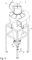
- FIG. 3 a possible embodiment of the cyclone 5 is shown in a three-dimensional view.
- Figures 4a and 4b show the cyclone 5 in longitudinal section and in the three-dimensional view in section.
- the powder-air mixture supplied to the cyclone 5 through the residual powder piping 4 flows tangentially at the inlet 21 in the inlet section 5.1 of the cyclone 5, which in the FIGS. 4a and 4b each shown schematically by an arrow.
- the powder-air mixture 20 flows past an air guide vane 14 and then spirally down in the cyclone 5 in the Abscheide Month 5.2 of the cyclone 5.
- the powder particles are due to the centrifugal force generated during the rotation of the air flow to the outside in the direction of the outer wall 24 of the cyclone fifth pressed.
- the powder particles are conveyed in the region of the outer wall 24 down in the direction of the powder outlet 25 of the cyclone and collected there. This is shown schematically by the arrows 27.
- a sieve 29 may be located at the bottom of the cyclone 5. The thus recovered and sieved powder can be removed via the powder outlet 25 of the cyclone.
- the freed for the most part of the powder particles air is sucked off via the arranged in the outlet tract 5.3 of the cyclone 5 dip tube 23 and a nozzle 50 and then passes to the outlet 22 of the cyclone.
- the dip tube 23 may, for example, have a length of 800 to 1100 mm and a diameter of 480 to 900 mm.
- the length of the dip tube 23 depends inter alia on the height of the cyclone 5.
- the dip tube 23 is preferably arranged so that its longitudinal axis is parallel to the longitudinal axis of the cyclone 5. In addition, it is generally advantageous if the longitudinal axis of the dip tube 23 coincides with the longitudinal axis of the cyclone 5, so that the dip tube 23 is arranged centrally in the cyclone 5 or in the outlet tract 5.3 of the cyclone 5.
- the nozzle 50 preferably protrudes down from the dip tube 23 at least 100 mm out.
- the air vortex 28 has the opportunity to apply itself to the blades 51. This prevents the air vortex 28 from being negatively influenced by the secondary flow 31. If the distributor 50 did not protrude from the dip tube 23, the secondary flow 31 could influence the flow angle of the air vortex 28 in such a way that shock losses occur. The shock losses would occur if the flow does not strike the blade 51 at the blade angle ⁇ .
- the diffuser 50 is arranged for the most part or entirely in the dip tube 23.
- One possible installation position of the distributor 50 is in the FIGS. 4a and 4b shown.
- the Figures 5a, 5b and 5c show a first possible embodiment of the installable into the cyclone 5 nozzle 50.
- the nozzle 50 is advantageously constructed rotationally symmetric and has a longitudinal axis LA. It has a cylindrical core 55, to which a cone or truncated cone 52 adjoins above. On the underside of the core 55 may be closed with a flat surface. This is not mandatory, but advantageous, because then in the interior of the core 55 no residual powder can deposit and the rising air flow can not get caught there.
- the course of the air flow through the nozzle along the vanes 51 is in FIG. 5a represented schematically by the two dashed arrows.
- the nozzle 50 also has a number of vanes 51, which are also referred to here as shovels in short. These may be mounted on the outside of the core 55. Instead, it is also possible to attach the guide vanes 51 to the dip tube 23. A part or all of the guide vanes 51 can also be fastened both to the core 55 and to the dip tube 23. The vanes 51 may be secured by welding, for example.
- the vanes 51 are preferably arranged equidistant from one another.
- the vane 51 has in bottom area 51.3 on a flat surface, which is slightly inclined relative to the horizontal plane. Preferably, it includes with the horizontal an angle ⁇ 'between 20 ° and 50 ° and even better between 30 ° and 37 °.
- the angle ⁇ ' is also referred to as the angle of attack.
- this inclined surface 51.3 joins in the central region 51.2 a curvature.
- the vane 51 has a flat, vertical surface 51.1.
- the flat surface is absent in the lower region 51.3. Instead, the vane is already curved at the lower end and then goes up into the flat, vertical surface above 51.1.
- both flat surfaces are missing. Instead, the vane is already curved at the lower end and the curvature extends to the upper end of the vane. There, the vane is curved so that the tangent of the curve is substantially vertical.
- the vanes 51 have the purpose of the ascending air vortex 28 (see FIGS. 4a and 4b ) and to transform as far as possible into a vertically directed air flow 30.
- the air flow is thus substantially free of eddies when it has passed the guide vanes 51 in the outlet region 50.2.
- the nozzle 50 Before the upwardly ascending air vortex 28 reaches the nozzle 50, it has a kinetic energy composed of a vertical (translational) portion and a rotational portion. With the aid of the guide apparatus 50, this rotational component of the kinetic energy is now converted into an additional translational kinetic energy. Thus, the rotatory component of the kinetic energy is not destroyed or converted into heat energy, but as mentioned, in an additional translational kinetic energy. This has the advantage, among other things, that the energy efficiency of the cyclone and thus also of the entire powder coating system increases.
- the longitudinal axis of the cyclone 5 does not have to, as in the FIGS. 1 to 4 shown to be vertically aligned.
- the cyclone 5 can also be arranged obliquely or horizontally, so that its longitudinal axis extends obliquely or horizontally.
- the longitudinal axis of the dip tube 23 and the guide tube 50 extend correspondingly obliquely or horizontally.
- distributor 50 another embodiment of the distributor can also be arranged in the dip tube 23.
- various possible embodiments of the distributor will be described.
- the holder 63 may be formed as a threaded rod with nut on which then the nozzle 60 is suspended. The position of the nozzle 60 in the dip tube 23 can be adjusted manually via the mother. Alternatively, the holder 63 may be a tongue-and-groove system having lock to adjust the position of the nozzle 60 can.
- the Figures 7a, 7b and 7c show a third possible embodiment of a can be installed in the cyclone 5 nozzle 70 in a three-dimensional view, in side view and in plan view.
- the diffuser 70 like the diffuser 60 has a holder 73 so that it can be attached to the top of the lid 15 of the cyclone 5.
- the guide vanes 71 are guided to the upper end of the cone 72 in the distributor 70.
- This embodiment has the advantage that the air flow, despite the low overall height of the distributor 70, has a longer calming distance. The area of the calming section is thus extended by the amount of the height of the cone. The efficiency of the distributor increases thereby.
- the Figures 8a, 8b and 8c show a fourth possible embodiment of an insertable into the cyclone 5 nozzle 80 in a three-dimensional view, in side view and in plan view.
- the diffuser 80 also has a cone 84 opposite the diffuser 70 on the underside.
- the flow is directed specifically to the path of the blades 81.
- both narrower and wider inner vertebrae are guided on the blades 81.
- the diffuser were flat on the underside, losses would be caused by the impact of the flow on the flat bottom. By means of the cone or truncated cone arranged on the underside, such impact losses can be minimized.
- the Figures 9a, 9b and 9c show a fourth possible embodiment of an insertable into the cyclone 5 nozzle 90 in a three-dimensional view, in side view and in plan view.
- the diffuser 90 has a shell 94 opposite the diffuser 80 on the underside instead of the cone.
- the shell 94 has the same purpose as the cone 84 or a truncated cone.
- the curvature of the shell 94 may be hemispherical, for example.
- the individual components of a diffuser can also be used in one of the other diffusers.
- the cone 84 of the nozzle 80 may also be used on the underside of the nozzle 50.
- the components of the diffusers can be combined as desired.
- the Figures 10a, 10b and 10c show a possible embodiment of a portion of the pipe 4 for the residual powder, which is sucked out of the cab 3.
- the pipeline 4 is also referred to herein as residual powder piping.
- the pipe 4 On the input side, the pipe 4 has a round cross section and on the output side a quadrangular cross section.
- the pipe 4 comprises a pipe adapter 41, which serves a pipe with a round cross-section, for example, the manifold 130 according to FIGS. 14a until e can be connected to a pipe with a quadrangular cross-section.
- a manifold 42 connects.
- the manifold 42 is a tube that causes a change in direction of the powder air flow by its curved shape.
- On the output side is the manifold 42 connected via a first and a second straight pipe section 43 with a second manifold 44. This in turn opens into a third straight piece of pipe 43.
- the manifold 44 and the manifold 42 may be identical. But this is not absolutely necessary.
- the manifold 42 may include a service door 45. Instead of integrating the maintenance door 45 in the manifold, the maintenance door 45 may also be provided in the pipeline 43. By means of the maintenance door 45, after a color change, it is possible to check the interior of the pipeline for contamination and, if necessary, to clean the pipeline.
- the maintenance door is in the FIGS. 10a to 11c shown open. It is closed during the coating operation.
- the components just described pipe adapter 41, manifold 42 and 44 and pipe sections 43 may be made as standard and have standard mass. They can be produced in stock and serve as standard components. With these, freely selectable pipe courses can then be formed.
- the in the Figures 10a, 10b and 10c shown pipe run is just one example. If required, any number of such components can be combined.
- the Figures 11a, 11b and 11c show a possible embodiment of the pipe 4 without the pipe adapter 41. If the manifold 44 and the pipe 43 have a square cross-section, the manifold 44 can be mounted in 90 ° increments on the pipe 43 and so the direction of the further course of the pipe 4 in 90 ° steps are set. But there are also any angle for the further course of the pipe 4 is possible. For example, two will do this Manifold or two pipes 43 each connected to a pipe adapter 41 and arranged so that the round cross-sections of the pipe adapter 41 lie on each other. Now any angle can be set for the continuation of the pipes.
- FIG. 12a A first possible embodiment of the manifold 42 is shown in FIG. 12a and a second possible embodiment of the manifold 42 is in FIG FIG. 12b shown in the side view.
- the manifold 42 shown there have, based on the two reference axes L1 and L2, a curvature angle ⁇ of 90 °.
- the powder air flow thus occurs deflected by 90 ° from the manifold 42.
- the manifold 42 can also be produced at any other angle of curvature ⁇ .
- the manifold 42 may be a bent sheet metal tube having a round or quadrangular tube cross-section. In this case, the wall 42.2 forms the wall 42.1 opposite wall.
- the wall 42.2 runs straight and then has a curvature in the area 42.22, which is also referred to below as an outer curve.
- the wall 42.1 has a greater curvature than the wall 42.2.
- the curvature 42.12 is also referred to below as the inside curve.
- the wall 42.1 is shorter than the wall 42.2 and is therefore also referred to as a short outer wall 42.1, whereas the wall 42.2 is also referred to as a long outer wall 42.2 of the manifold 42.
- Curvature is also understood to mean a shape formed by a polygon, which substantially corresponds to the desired curved course.
- the curvature can be generated both by a circular arc and by a polygon.
- a quarter circle can also be formed by a polygon with 4 to 8 corners.
- the number of corners of the polygon should be chosen so large that in the polygon no too sharp corners or sharp edges arise because otherwise there would be a stall and powder could deposit there. This applies mutatis mutandis to the inner curve and the outer curve of the bend, which can be formed for example by circular arcs, elliptical sections, arc segments or polygons.
- the curvature of the opposite wall 42.2 may have a radius R2 in a first region 42.22 of the curvature and a radius R3 in a second region 42.23 of the curvature. In the two areas 42.22 and 42.23, the two curvatures are in opposite directions.
- the course of the curvature in the wall 42.2 is first concave and then convex.
- the entire curvature of the wall 42.2 is formed so that a bulge 42.24 results in the wall 42.2.
- the bulge 42.24 enlarges the pipe cross-section.
- the region 42.23 can also be formed in a straight line.
- the wall in the region 42.23 is formed by an oblique surface, which merges tangentially into the convex curvature in the region 42.22.
- the powder-air mixture can flow through the opening 42.3 in the manifold 42 and exit through the opening 42.4 again from the manifold.
- the arrow 20 indicates the flow direction of the powder-air mixture.
- the manifold 42 can also be flowed through in the opposite direction by the powder-air mixture.
- the arrow 20 "indicates the flow direction of the powder-air mixture FIG. 11c the manifold 44 is shown in a first installation position, so that the bulge is located on the top of the manifold.
- the powder particles strike the wall 42.2 of the manifold in the area of the bulge 42.24.
- the bulge 42.24 thus serves as a baffle for the powder particles.
- the powder particles are braked without friction. Since there is no appreciable friction, it prevents the particles from being able to sinter there. Due to the permanent air flow, the particles are then transported from there to the outlet opening of the manifold.
- the baffle is preferably between D / 2 and D wide, where D is the width of the opening 42.3 of the manifold 42.
- the manifold 42 can also be flowed through in the opposite direction.
- the powder air stream then flows according to the arrow 20 "through the opening 42.4 in the manifold 42.
- the permanent air flow then transports the particles therefrom to the outlet opening of the bend, which in this case is the opening 42.3
- the baffle PF serves that surface of the manifold 42 onto which the powder particles perpendicular or nearly vertical incident.
- the baffle PF is preferably between D / 2 and D wide, where D is the width of the opening 42.4 of the manifold 42.
- the pressure losses are, regardless of whether the air flow from the direction 20 'or 20 "flows through the manifold 42, in both cases similarly large.
- the long outer wall 42.2 has a radius R4 and runs as they are in FIG. 12a indicated by dashed lines. It can be seen that in the previously known manifold there is virtually no or only a relatively small impact surface for the powder particles. Most of the powder particles strike the long outer wall at a relatively shallow angle. The particles are heated by friction, so that they can adhere to the long outer wall in the course of time or can ansintern there.
- the in FIG. 12b shown manifold 42 differs from the manifold according to FIG. 12a by the position and the course of the outer curve.
- the outer curve 42.22 and 42.24 is further towards the center line or reference axis L1 outside offset as it according to the outer curve FIG. 12a the case is.
- the offset X1 of the center of curvature 42.22 with respect to the center line L1 is thus at the manifold according to FIG. 12b bigger than at FIG. 12a ,
- the outer curve in the area 42.23 is shaped differently.
- FIGS. 13a, 13b, 13c and 13d shows a possible embodiment of the tube adapter 41 in a three-dimensional view, the side view, the view from the front and from behind.
- the tube adapter 41 has a round opening 41.1 and a quadrangular opening 41.2.
- About corresponding flanges of the tube adapter 41 can be connected to round or square tubes.
- FIGS. 14a, 14b, 14c, 14d and 14e show a possible embodiment of the manifold 130 in different views.
- suction pipes for overspray the two suction pipes open into the two connecting pieces 131 and 132 of the manifold 130.
- the outlet 133 of the manifold 130 in turn can be performed on the tube adapter 41 or connected directly to the residual powder line 4, if their tube cross sections are the same.
- the outlet 133 opposite the end of the manifold 130 is closed with a revision cover 134. If necessary, the inspection cover 134 can be removed and the interior of the collection tube 130 can be cleaned.
- the collecting pipe has a first diameter D1 in the region of the inspection cover 134 and a second diameter D2 at the outlet 133, the diameter D1 being smaller than the diameter D2.
- the cross section of the manifold 130 towards the outlet 133 increases toward and preferably
- the cross section of the manifold 130 towards the outlet 133 increases constantly. In this way it is achieved that the flow velocities of the residual powder air flows in the two suction tubes of the car are the same size or almost the same size. This has the advantage that about the same amount of air per unit time are sucked on the one longitudinal side and the other longitudinal side of the cabin.
- the angle ⁇ indicates the change in the diameter of the manifold 130 and depends inter alia on the cabin width. The wider the cabin, the smaller the angle should be.
- the angle ⁇ is preferably in the range of 1 ° to 4 °.
- the angle ⁇ is in the range of 1 ° to 3 °, and more preferably in the range of 2 ° to 3 °.
- FIG. 15a is the baffle 15 in a three-dimensional view and in FIG. 15b shown in the side view.
- the fan-shaped end 16 of the vane 14 is located on the downstream side of the vane.
- the guide vanes 51 may also have teeth or fanned in the outlet region 51.1.
- the outlet area 51. 1 can be designed to be similar to that of the fan-shaped ends 16 of the guide blade 14.
- a coating booth 3 In the powder coating installation for coating workpieces with coating powder, a coating booth 3, a cyclone 5 and a filter 9 may be provided, the coating booth 3 being connected to the cyclone 5 via a residual powder pipeline 4. But it is also possible that the coating booth 3 is connected to the filter 9 via the residual powder piping 4.
Landscapes
- Engineering & Computer Science (AREA)
- General Engineering & Computer Science (AREA)
- Mechanical Engineering (AREA)
- Physics & Mathematics (AREA)
- Fluid Mechanics (AREA)
- Cyclones (AREA)
- Coating Apparatus (AREA)
- Details Or Accessories Of Spraying Plant Or Apparatus (AREA)
- Electrostatic Spraying Apparatus (AREA)
Description
Die Erfindung betrifft eine Pulverbeschichtungsanlage zum Beschichten von Werkstücken mit Beschichtungspulver.The invention relates to a powder coating system for coating workpieces with coating powder.
Bei der elektrostatischen Beschichtung von Werkstücken mit Pulver wird dieses über eine oder mehrere Pulversprühpistolen auf das zu beschichtende Werkstück aufgesprüht. Die zu beschichtenden Werkstücke befinden sich während des Beschichtungsvorgangs in der Regel innerhalb einer Pulverbeschichtungskabine, die im Folgenden auch kurzum als Kabine bezeichnet wird. Da beim Beschichtungsvorgang nicht alle von den Sprühpistolen versprühten Pulverpartikel auf den zu beschichtenden Werkstücken haften bleiben, muss das überschüssige Pulver, welches auch als Overspray bezeichnet wird, aus der Kabine wieder entfernt werden. Dies ist zum einen deshalb notwendig, weil die Umgebung außerhalb der Kabine frei von Pulverstaub zu halten ist. Zum anderen steigt die Explosionsgefahr bei einer Überschreitung einer bestimmten Pulverkonzentration durch die in der Kabine schwebende Pulverstaubwolke. Dies gilt es zu vermeiden. Überschüssiges Pulver bereits während des Betriebs aus dem Inneren der Kabine abzusaugen hat zudem den Vorteil, dass bei einem Farbwechsel die erforderlichen Reinigungsmaßnahmen weniger Zeit in Anspruch nehmen, weil sich grundsätzlich weniger Restpulver in der Kabine befindet. Werden die Kabine und das Absaugsystem nicht ausreichend gereinigt, kann es nach einem Farbwechsel zu einer unerwünschten Farbverschleppung kommen.In the electrostatic coating of workpieces with powder this is sprayed on one or more powder spray guns on the workpiece to be coated. During the coating process, the workpieces to be coated are usually located inside a powder coating booth, which will also be referred to below as the cabin. Since during the coating process not all powder particles sprayed by the spray guns adhere to the workpieces to be coated, the excess powder, which is also referred to as overspray, must be removed from the booth again. This is necessary on the one hand because the environment outside the cabin is to be kept free of powder dust. On the other hand, the danger of explosion when exceeding a certain powder concentration by the powder dust cloud floating in the cabin increases. This should be avoided. Extracting excess powder already during operation from the interior of the cabin also has the advantage that in a color change the required Cleaning takes less time, because there is basically less residual powder in the cabin. If the cabin and the exhaust system are not cleaned sufficiently, a color change can result in undesirable color carryover.
Um das Overspray aus der Kabine zu entfernen, wird es zusammen mit der in der Kabine befindlichen Luft als Pulver-Luftgemisch aus der Kabine gesaugt und einem Zyklon zugeführt, der als Monozyklon ausgebildet sein kann. Ein derartiger Zyklon ist aus der Druckschrift
In der Regel sind hierfür zwischen 15000 und 30000 m3 Luft pro Stunde erforderlich, die von einem elektrisch betriebenen Ventilator oder Gebläse bereitgestellt werden. Die Energiekosten hierfür sind nicht unerheblich.As a rule, this requires between 15,000 and 30,000 m 3 of air per hour, which are provided by an electrically operated fan or blower. The energy costs for this are not insignificant.
Eine Aufgabe der Erfindung ist es, eine Pulverbeschichtungsanlage zum Beschichten von Werkstücken mit Beschichtungspulver anzugeben, bei der der Energieverbrauch der Pulverbeschichtungsanlage minimiert wird. Insbesondere der (elektrische) Leistungsbedarf für die Bereitstellung der Saugluft für den Zyklon soll minimiert werden. Dies soll jedoch nicht auf Kosten der Zeit gehen, die für einen Farbwechsel nötig ist. Der Farbwechsel soll also genauso schnell oder noch schneller von statten gehen können, ohne dass es zu einer Farbverschleppung kommt.An object of the invention is a powder coating system for coating workpieces with coating powder in which the energy consumption of the powder coating system is minimized. In particular, the (electrical) power requirement for the provision of the suction air for the cyclone should be minimized. However, this should not be at the expense of the time required for a color change. The color change should therefore be able to do just as fast or faster, without causing a color carryover.
Vorteilhafter Weise ist die Pulverbeschichtungsanlage strömungstechnisch dahingehend optimiert, dass sich kein oder nur sehr wenig Pulver ablagern beziehungsweise ansintern kann. Auch dies dient dem schnellen Farbwechsel ohne Farbverschleppung. Der Zeitaufwand für die Reinigung der Pulverbeschichtungsanlage wird minimiert.Advantageously, the powder coating system is aerodynamically optimized so that no or very little powder can deposit or ansintern. This also serves the fast color change without Farbverschleppung. The time required for cleaning the powder coating system is minimized.
Die Aufgabe wird durch eine Pulverbeschichtungsanlage zum Beschichten von Werkstücken mit Beschichtungspulver mit den in Patentanspruch 1 angegebenen Merkmalen gelöst.The object is achieved by a powder coating system for coating workpieces with coating powder having the features specified in
Die erfindungsgemässe Pulverbeschichtungsanlage zum Beschichten von Werkstücken mit Beschichtungspulver weist eine Beschichtungskabine und ein Zyklon auf, wobei die Beschichtungskabine über eine Restpulverrohrleitung mit dem Zyklon verbunden ist. Der Zyklon umfasst im Auslasstrakt ein Tauchrohr, in dem ein Leitapparat angeordnet ist, der mehrere Schaufeln aufweist. Diese sind derart ausgebildet, dass der auf die Schaufeln auftreffende Luftwirbel wenigstens teilweise in einen wirbelfreien Luftstrom umlenkbar ist.The powder coating system according to the invention for coating workpieces with coating powder has a coating booth and a cyclone, wherein the coating booth is connected to the cyclone via a residual powder pipeline. The cyclone comprises in the outlet tract a dip tube in which a nozzle is arranged, which has a plurality of blades. These are designed in such a way that the air vortex impinging on the blades can be deflected at least partially into an eddy-free air flow.
Falls die Längsachse des Leitapparats vertikal verläuft, sind die Schaufeln derart ausgebildet, dass der auf die Schaufeln auftreffende Luftwirbel wenigstens teilweise in einen vertikalen Luftstrom umlenkbar ist.If the longitudinal axis of the distributor extends vertically, the blades are designed such that the on the Blades impinging air vortex is at least partially deflected into a vertical air flow.
Vorteilhafte Weiterbildungen der Erfindung ergeben sich aus den in den abhängigen Patentansprüchen angegebenen Merkmalen.Advantageous developments of the invention will become apparent from the features indicated in the dependent claims.
Bei einer Ausführungsform der erfindungsgemässen Pulverbeschichtungsanlage sind die Schaufeln radial zur Längsachse des Leitapparats angeordnet. Ein solcher Leitapparat kann einfach und kostengünstig hergestellt werden.In one embodiment of the inventive powder coating system, the blades are arranged radially to the longitudinal axis of the distributor. Such a diffuser can be easily and inexpensively manufactured.
Bei einer weiteren Ausführungsform der erfindungsgemässen Pulverbeschichtungsanlage sind die Schaufeln im Einlassbereich gekrümmt. Falls die Längsachse des Leitapparats vertikal verläuft, befindet sich der gekrümmte Bereich unten an den Schaufeln. Dadurch kann der Luftwirbel noch besser in einen vertikalen Luftstrom umgelenkt werden. Die Luft prallt nicht auf die Schaufeln, sondern trifft in einem flachen Winkel auf sie, so dass Energieverluste weiter reduziert werden.In a further embodiment of the powder coating system according to the invention, the blades are curved in the inlet region. If the longitudinal axis of the nozzle is vertical, the curved portion is at the bottom of the blades. As a result, the air vortex can be better redirected into a vertical air flow. The air does not hit the blades but hits them at a shallow angle, further reducing energy losses.
Es ist von Vorteil, wenn wenigstens eine der Schaufeln im Einlassbereich mit der Längsachse des Leitapparats einen Winkel zwischen 40° und 70° und noch besser Winkel zwischen 53° und 60° einschliesst.It is advantageous if at least one of the blades in the inlet region with the longitudinal axis of the distributor encloses an angle between 40 ° and 70 ° and even better angle between 53 ° and 60 °.
Bei einer zusätzlichen Ausführungsform der erfindungsgemässen Pulverbeschichtungsanlage sind die Schaufeln im Auslassbereich geradlinig ausgebildet. Falls die Längsachse des Leitapparats senkrecht verläuft, befindet sich der geradlinige Bereich oben an den Leitschaufeln. Auch dadurch werden die Luftwirbel noch besser in einen vertikalen Luftstrom umgelenkt.In an additional embodiment of the powder coating system according to the invention, the blades are rectilinear in the outlet region. If the longitudinal axis of the nozzle is vertical, the rectilinear area is at the top of the vanes. Also As a result, the air vortices are better redirected into a vertical airflow.
Zudem kann beim Leitapparat der erfindungsgemässen Pulverbeschichtungsanlage vorgesehen sein, dass wenigstens ein Teil der Schaufeln im Auslassbereich eine Fläche aufweist, die parallel zur Längsachse ausgerichtet ist.In addition, it can be provided in the distributor of the powder coating system according to the invention that at least part of the blades in the outlet region has a surface which is aligned parallel to the longitudinal axis.
Bei einer Weiterbildung der erfindungsgemässen Pulverbeschichtungsanlage verjüngt sich der Leitapparat auf seiner stromabwärtigen Seite. Wenn der Leitapparat senkrecht angeordnet ist, kann vorgesehen sein, dass er sich nach oben hin verjüngt. Hierdurch werden Strömungsabrisse am oberen Ende des Leitapparats vermieden.In a development of the powder coating system according to the invention, the distributor tapers on its downstream side. If the distributor is arranged vertically, it can be provided that it tapers towards the top. As a result, stalls are avoided at the upper end of the nozzle.
Bei einer anderen Weiterbildung der erfindungsgemässen Pulverbeschichtungsanlage weist der Leitapparat eine Halterung auf, mit der er im Tauchrohr angeordnet werden kann. Dies ist insbesondere für das Nachrüsten eines Zyklons hilfreich. Die Halterung kann zum Beispiel oben, unten oder seitlich am Leitapparat vorgesehen sein.In another development of the powder coating system according to the invention, the diffuser has a holder with which it can be arranged in the immersion tube. This is especially helpful for retrofitting a cyclone. The holder may be provided, for example, top, bottom or side of the nozzle.
Darüber hinaus kann bei der erfindungsgemässen Pulverbeschichtungsanlage vorgesehen sein, dass sich der Leitapparat auf seiner stromaufwärtigen Seite verjüngt. Wenn der Leitapparat senkrecht angeordnet ist, kann vorgesehen sein, dass er sich nach unten hin verjüngt. Die aufsteigende Luft prallt dadurch nicht auf die Unterseite des Leitapparats, sondern trifft in einem flachen Winkel auf ihn, so dass die Energieverluste weiter reduziert werden können.In addition, it can be provided in the powder coating system according to the invention that the distributor tapers on its upstream side. If the nozzle is arranged vertically, it can be provided that it tapers downwards. As a result, the rising air does not hit the bottom of the nozzle, but hits it at a shallow angle, so that the energy losses can be further reduced.
Zudem ist bei der erfindungsgemässen Pulverbeschichtungsanlage im Einlasstrakt des Zyklons eine gefächerte Leitschaufel vorgesehen.In addition, a fan-shaped vane is provided in the inventive powder coating system in the inlet tract of the cyclone.
Bei der erfindungsgemässen Pulverbeschichtungsanlage ist es auch möglich, dass die gefächerte Leitschaufel tangential zum in den Zyklon eintretenden Pulver-Luftstrom angeordnet ist.In the case of the powder coating system according to the invention, it is also possible that the fan-shaped guide blade is arranged tangentially to the powder air stream entering the cyclone.
Bei einer Weiterbildung der erfindungsgemässen Pulverbeschichtungsanlage ist entlang der Längsseiten der Beschichtungskabine jeweils eine Restpulverrohrleitung angeordnet. Zudem ist ein Sammelrohr vorgesehen, das quer zu den Restpulverrohrleitungen verläuft und in das die Restpulverrohrleitungen münden. Das Sammelrohr weist einen Querschnitt auf, der sich über die Länge des Sammelrohrs im Wesentlichen kontinuierlich erweitert. Weil die beiden an den Längsseiten der Beschichtungskabine angeordneten Restpulverrohrleitungen nun jeweils die gleiche Luftmenge absaugen, muss man bei der Dimensionierung der aus der Kabine abzusaugenden Luftmenge nicht mehr von der Restpulverrohrleitung mit der geringeren Saugleistung ausgehen. Somit kann man die pro Zeiteinheit aus der Kabine abgesaugte Luftmenge reduzieren, was den Energieverbrauch der Anlage weiter reduziert.In a development of the powder coating system according to the invention, in each case a residual-powder pipeline is arranged along the longitudinal sides of the coating booth. In addition, a collecting pipe is provided, which extends transversely to the residual powder pipelines and into which the residual powder pipelines open. The manifold has a cross-section which widens substantially continuously over the length of the manifold. Because the two arranged on the longitudinal sides of the coating booth residual powder pipelines now each suck the same amount of air, you must go out in the dimensioning of the air to be sucked from the cabin no longer from the residual powder pipe with the lower suction power. Thus, you can reduce the amount of air extracted from the cabin per unit time, which further reduces the energy consumption of the system.
Zudem wird eine Pulverbeschichtungsanlage zum Beschichten von Werkstücken mit Beschichtungspulver vorgeschlagen, die eine Beschichtungskabine und ein Zyklon und/oder ein Filter aufweist. Die Beschichtungskabine ist über eine Restpulverrohrleitung mit dem Zyklon oder dem Filter verbunden. Die Restpulverrohrleitung weist mindestens einen Krümmer auf, um den Pulver-Luftstrom in eine andere Richtung zu lenken. Der Krümmer umfasst eine kurze, gekrümmte Aussenwand und eine lange, gekrümmte Aussenwand, wobei die lange, gekrümmte Aussenwand eine Ausbuchtung aufweist.In addition, a powder coating system for coating workpieces with coating powder is proposed which has a coating booth and a cyclone and / or a filter. The coating booth is connected to the cyclone or filter via a residual powder pipeline. The residual powder piping has at least one manifold to direct the powder airflow in a different direction to steer. The manifold comprises a short, curved outer wall and a long, curved outer wall, with the long, curved outer wall having a bulge.
Schliesslich kann bei der erfindungsgemässen Pulverbeschichtungsanlage vorgesehen sein, dass der Krümmer eine Innenkurve aufweist, die Teil der kurzen Aussenwand ist. Zudem weist der Krümmer eine Aussenkurve auf, die Teil der langen Aussenwand ist. Die lange Aussenwand weist einen geraden Abschnitt auf, an den sich die Aussenkurve tangential anschliesst.Finally, in the case of the powder coating system according to the invention, provision can be made for the elbow to have an inner curve which is part of the short outer wall. In addition, the manifold has an outer curve, which is part of the long outer wall. The long outer wall has a straight section to which the outer curve connects tangentially.
Im Folgenden wird die Erfindung mit mehreren Ausführungsbeispielen anhand von mehreren Figuren weiter erläutert.
Figur 1- zeigt eine mögliche Ausführungsform einer Pulverbeschichtungsanlage zum Beschichten von Werkstücken mit Beschichtungspulver in der Seitenansicht.
Figur 2- zeigt die Pulverbeschichtungsanlage zum Beschichten von Werkstücken mit Beschichtungspulver in der Draufsicht.
Figur 3- zeigt eine mögliche Ausführungsform eines Zyklons in einer dreidimensionalen Ansicht.
- Figuren 4a und 4b
- zeigen den Zyklon im Längsschnitt beziehungsweise in der dreidimensionalen Ansicht im Schnitt.
- Figuren 5a, 5b und 5c
- zeigen eine erste mögliche Ausführungsform eines in den Zyklon einbaubaren Leitapparats.
- Figuren 6a, 6b und 6c
- zeigen eine zweite mögliche Ausführungsform des in den Zyklon einbaubaren Leitapparats.
- Figuren 7a, 7b und 7c
- zeigen eine dritte mögliche Ausführungsform des in den Zyklon einbaubaren Leitapparats.
- Figuren 8a, 8b und 8c
- zeigen eine vierte mögliche Ausführungsform des in den Zyklon einbaubaren Leitapparats.
- Figuren 9a, 9b und 9c
- zeigen eine vierte mögliche Ausführungsform des in den Zyklon einbaubaren Leitapparats.
- Figuren 10a, 10b und 10c
- zeigen eine mögliche Ausführungsform einer Rohrleitung für den Restpulverluftstrom mit einem Rohradapter in einer dreidimensionalen Ansicht und in zwei Seitenansichten.
- Figuren 11a, 11b und 11c
- zeigen eine weitere mögliche Ausführungsform der Rohrleitung für den Restpulverluftstrom in einer dreidimensionalen Ansicht und in zwei Seitenansichten.
- Figur 12a
- zeigt eine erste mögliche Ausführungsform eines Krümmers in der Seitenansicht, der in die Rohrleitung für den Restpulverluftstrom einbaubar ist.
- Figur 12b
- zeigt eine zweite mögliche Ausführungsform des Krümmers in der Seitenansicht, der in die Rohrleitung für den Restpulverluftstrom einbaubar ist.
- Figuren 13a, 13b, 13c und 13d
- zeigen eine mögliche Ausführungsform des Rohradapters in verschiedenen Ansichten.
- Figuren 14a, 14b, 14c, 14d und 14e
- zeigen eine mögliche Ausführungsform eines Sammelrohrs für den Restpulverluftstrom in verschiedenen Ansichten.
- Figuren 15a und 15b
- zeigen eine mögliche Ausführungsform eines Luftleitblechs in der dreidimensionalen Ansicht und in der Seitenansicht.
- FIG. 1
- shows a possible embodiment of a powder coating system for coating workpieces with coating powder in the side view.
- FIG. 2
- shows the powder coating system for coating workpieces with coating powder in plan view.
- FIG. 3
- shows a possible embodiment of a cyclone in a three-dimensional view.
- FIGS. 4a and 4b
- show the cyclone in longitudinal section and in the three-dimensional view in section.
- Figures 5a, 5b and 5c
- show a first possible embodiment of an installable into the cyclone nozzle.
- Figures 6a, 6b and 6c
- show a second possible embodiment of the installable into the cyclone nozzle.
- Figures 7a, 7b and 7c
- show a third possible embodiment of the installable into the cyclone nozzle.
- Figures 8a, 8b and 8c
- show a fourth possible embodiment of the installable in the cyclone nozzle.
- Figures 9a, 9b and 9c
- show a fourth possible embodiment of the installable in the cyclone nozzle.
- Figures 10a, 10b and 10c
- show a possible embodiment of a pipeline for the residual powder air flow with a tube adapter in a three-dimensional view and in two side views.
- Figures 11a, 11b and 11c
- show a further possible embodiment of the pipeline for the residual powder air flow in a three-dimensional view and in two side views.
- FIG. 12a
- shows a first possible embodiment of a manifold in the side view, which is installable in the pipeline for the residual pulse air flow.
- FIG. 12b
- shows a second possible embodiment of the manifold in the side view, which is installed in the pipeline for the residual pulse air flow.
- Figures 13a, 13b, 13c and 13d
- show a possible embodiment of the tube adapter in different views.
- Figures 14a, 14b, 14c, 14d and 14e
- show a possible embodiment of a collecting tube for the residual pulse air flow in various views.
- FIGS. 15a and 15b
- show a possible embodiment of a baffle in the three-dimensional view and in the side view.
In
In
Das Tauchrohr 23 kann beispielsweise eine Länge von 800 bis 1100 mm und einen Durchmesser von 480 bis 900 mm haben. Die Länge des Tauchrohrs 23 hängt unter anderem von der Höhe des Zyklons 5 ab. Durch eine Reihe von Versuchen hat man herausgefunden, dass es einen Zusammenhang zwischen dem Abscheidegrad des Tauchrohrs 23 und der Abscheidung in der Hauptströmung gibt. Mit zunehmender Länge des Tauchrohrs 23 steigt zwar der Abscheidegrad im Tauchrohr 23, die Abscheidung in der Hauptströmung wird dadurch jedoch negativ beeinflusst.The
Das Tauchrohr 23 ist vorzugsweise so angeordnet, dass dessen Längsachse parallel zur Längsachse des Zyklons 5 verläuft. Zudem ist es in der Regel von Vorteil, wenn die Längsachse des Tauchrohrs 23 mit der Längsachse des Zyklons 5 zusammenfällt, so dass das Tauchrohr 23 im Zyklon 5 beziehungsweise im Auslasstrakt 5.3 des Zyklons 5 zentrisch angeordnet ist.The
Der Leitapparat 50 ragt vorzugsweise unten aus dem Tauchrohr 23 mindestens 100 mm heraus. Dadurch hat der Luftwirbel 28 die Möglichkeit sich an die Schaufeln 51 anzulegen. So wird verhindert, dass der Luftwirbel 28 von der Sekundärströmung 31 negativ beeinflusst werden kann. Würde der Leitapparat 50 nicht aus dem Tauchrohr 23 herausragen, könnte die Sekundärströmung 31 den Strömungswinkel des Luftwirbels 28 so beeinflussen, dass Stossverluste entstehen. Die Stossverluste würden entstehen, wenn die Strömung nicht im Schaufelwinkel ε auf die Schaufel 51 trifft.The
Der Leitapparat 50 ist zum grössten Teil oder ganz im Tauchrohr 23 angeordnet. Eine mögliche Einbaulage des Leitapparats 50 ist in den
Die
Der Leitapparat 50 weist zudem eine Reihe von Leitschaufeln 51 auf, die hier auch kurzum als Schaufeln bezeichnet werden. Diese können auf der Aussenseite des Kerns 55 befestigt sein. Statt dessen ist es aber auch möglich, die Leitschaufeln 51 am Tauchrohr 23 zu befestigen. Ein Teil oder sämtliche Leitschaufeln 51 können auch sowohl am Kern 55 als auch am Tauchrohr 23 befestigt sein. Die Leitschaufeln 51 können zum Beispiel durch Schweissen befestigt werden.The
Wenn der Leitapparat 50 in das Tauchrohr 23 hineingeschoben wird, ist es von Vorteil, wenn zwischen den Leitschaufeln 51 und dem Tauchrohr 23 keine oder möglichst geringe Luftspalte bestehen.When the
Der gesamte Leitapparat oder Teile davon können zum Beispiel aus Stahl, Aluminium oder leitfähigem Kunststoff hergestellt werden. Als Herstellungsverfahren sind beispielsweise Schweissen, Giessen oder Rapid-Manufacturing, wie Sintern oder 3D-Drucken, denkbar.The entire diffuser or parts thereof can be made of steel, aluminum or conductive plastic, for example. As a manufacturing process, for example, welding, casting or rapid manufacturing, such as sintering or 3D printing, conceivable.
Die Leitschaufeln 51 sind vorzugsweise äquidistant zueinander angeordnet.The
Im Folgenden wird die Form der Leitschaufeln 51 anhand einer Schaufel erläutert. Vorzugsweise haben alle Schaufeln 51 die gleiche Form. Die Leitschaufel 51 weist im unteren Bereich 51.3 eine ebene Fläche auf, die gegenüber der horizontalen Ebene leicht geneigt ist. Vorzugsweise schliesst sie mit der Horizontalen einen Winkel ε' zwischen 20° und 50° und noch besser zwischen 30° und 37° ein. Der Winkel ε' wird auch als Anströmwinkel bezeichnet. Auf die Längsachse LA des Leitapparats 50 bezogen, heisst das, dass die Leitschaufel 51 mit der Längsachse LA einen Winkel ε (ε = 90° - ε') zwischen 40° und 70° und noch besser zwischen 53° und 60° einschliesst. An diese schräge Fläche 51.3 schliesst sich im mittleren Bereich 51.2 eine Krümmung an. Im oberen Bereich 51.1 weist die Leitschaufel 51 eine ebene, senkrechte Fläche 51.1 auf.In the following, the shape of the
Die gekrümmte Fläche 51.2 kann an ihrem unteren Ende tangential in die ebene Fläche 51.3 und/oder an ihrem oberen Ende tangential in die senkrechte Fläche 51.1 übergehen. Auf diese Weise werden an den Übergängen der Flächen 51.1 zu 51.2 und 51.2 zu 51.3 Kanten vermieden, so dass dort die Gefahr einer Pulverablagerung reduziert wird.The curved surface 51.2 can transition tangentially into the flat surface 51.3 at its lower end and / or tangentially into the vertical surface 51.1 at its upper end. In this way, at the transitions of the surfaces 51.1 to 51.2 and 51.2 to 51.3 edges are avoided, so that there the risk of powder deposition is reduced.
Bei einer weiteren Ausführungsform der Leitschaufel 51 fehlt die ebene Fläche im unteren Bereich 51.3. Statt dessen ist die Leitschaufel bereits am unteren Ende gekrümmt und geht dann oben in die ebene, senkrechte Fläche über 51.1.In a further embodiment of the
Bei einer anderen Ausführungsform der Leitschaufel 51 fehlen beide ebenen Flächen. Statt dessen ist die Leitschaufel bereits am unteren Ende gekrümmt und die Krümmung erstreckt sich bis zum oberen Ende der Leitschaufel. Dort ist die Leitschaufel so gekrümmt, dass die Tangente der Krümmung im Wesentlichen vertikal ist.In another embodiment of the
Die Leitschaufeln 51 sind vorzugsweise an der Mantelfläche des Kerns 55 radial, das heisst geradlinig vom Zentrum des Kerns 55 ausgehend, angeordnet. Bei einer Ausführungsform des Leitapparats sind 16 Schaufeln vorgesehen. Vorzugsweise liegt die Zahl der Schaufeln zwischen 10 und 25.The guide vanes 51 are preferably arranged radially on the lateral surface of the core 55, that is to say in a straight line starting from the center of the
Die Leitschaufeln 51 haben den Zweck, den aufsteigenden Luftwirbel 28 (siehe
Wenn die Luft an den Schaufeln 51 vorbeiströmt, können im Auslassbereich 50.2 der Schaufeln 51 Ablösewirbel entstehen. Diese sind jedoch hier nicht von Belang.When the air flows past the
Bevor der nach oben aufsteigende Luftwirbel 28 den Leitapparat 50 erreicht, besitzt er eine Bewegungsenergie, die sich aus einem vertikalen (translatorischen) Anteil und einem rotatorischen Anteil zusammensetzt. Mit Hilfe des Leitapparats 50 wird nun dieser rotatorische Anteil der Bewegungsenergie in eine zusätzliche translatorische Bewegungsenergie umgewandelt. Damit wird der rotatorische Anteil der Bewegungsenergie nicht vernichtet beziehungsweise in Wärmeenergie umgewandelt, sondern wie erwähnt, in eine zusätzliche translatorische Bewegungsenergie. Das hat unter anderem den Vorteil, dass der energetische Wirkungsgrad des Zyklons und damit auch der der gesamten Pulverbeschichtungsanlage steigt.Before the upwardly ascending
Grundsätzlich muss die Längsachse des Zyklons 5 nicht, wie in den
Statt des Leitapparats 50 kann auch eine andere Ausführungsform des Leitapparats im Tauchrohr 23 angeordnet sein. Im Folgenden werden verschiedene, mögliche Ausführungsformen des Leitapparats beschrieben.Instead of the
Die
Statt den Leitapparat 60 in einer festen Höhe in das Tauchrohr 23 einzubauen, kann er auch in der Höhe einstellbar sein. Die Halterung 63 kann als Gewindestange mit Mutter ausgebildet sein, an der dann der Leitapparat 60 aufgehängt wird. Die Position des Leitapparates 60 im Tauchrohr 23 kann manuell über die Mutter eingestellt werden. Alternativ dazu kann die Halterung 63 ein Nut-Federsystem mit Arretierung aufweisen, um die Position des Leitapparates 60 einstellen zu können.Instead of installing the
Die
Die
Die
Die einzelnen Komponenten eines Leitapparates können auch bei einem der anderen Leitapparate eingesetzt werden. So kann zum Beispiel der Kegel 84 des Leitapparats 80 auch auf der Unterseite des Leitapparats 50 verwendet werden. Die Komponenten der Leitapparate sind beliebig miteinander kombinierbar.The individual components of a diffuser can also be used in one of the other diffusers. For example, the
Die
Die Rohrleitung 4 umfasst einen Rohradapter 41, der dazu dient ein Rohr mit einem runden Querschnitt, das beispielsweise das Sammelrohr 130 gemäss
Der Krümmer 42 kann eine Wartungstür 45 aufweisen. Statt die Wartungstür 45 in den Krümmer zu integrieren, kann die Wartungstür 45 auch in der Rohrleitung 43 vorgesehen sein. Mittels der Wartungstür 45 kann man nach einem Farbwechsel das Innere der Rohrleitung auf Verschmutzung hin prüfen und die Rohrleitung gegebenenfalls reinigen. Die Wartungstür ist in den
Die soeben beschriebenen Bauteile Rohradapter 41, Krümmer 42 und 44 und Rohrstücke 43 können serienmässig hergestellt sein und Standardmasse aufweisen. Sie können auf Lager produziert werden und als Standardbauteile dienen. Mit diesen können dann frei wählbare Rohrverläufe gebildet werden. Der in den
Die Bauteile 41 - 44 der Rohrleitung 4 können aus Blech hergestellt sein.The components 41-44 of the
Eine erste mögliche Ausführungsform des Krümmers 42 ist in
Die Wand 42.1 ist kürzer als die Wand 42.2 und wird daher auch als kurze Aussenwand 42.1 bezeichnet, wohingegen die Wand 42.2 auch als lange Aussenwand 42.2 des Krümmers 42 bezeichnet wird.The wall 42.1 is shorter than the wall 42.2 and is therefore also referred to as a short outer wall 42.1, whereas the wall 42.2 is also referred to as a long outer wall 42.2 of the manifold 42.
Die Krümmung der Wand 42.1 kann einen über die gesamte Krümmung hinweg konstanten Radius R1 aufweisen, was aber nicht zwingend ist. Grundsätzlich kann die Wand 42.1 mehr oder weniger beliebig konkav gekrümmt sein. Vorteilhafter Weise ist die Krümmung im Bereich 42.12 jedoch nicht so gross, dass sie - strömungstechnisch gesehen - eine Ecke bildet, weil sich dort sonst Pulver ablagern könnte.The curvature of the wall 42.1 may have a constant across the entire curvature radius R1, but this is not mandatory. In principle, the wall 42.1 can be more or less arbitrarily concavely curved. Advantageously, however, the curvature in the region 42.12 is not so great that, in terms of flow, it forms a corner, because otherwise powder could be deposited there.
Unter Krümmung wird auch eine durch ein Polygon gebildete Form verstanden, die im Wesentlichen dem gewünschten gekrümmten Verlauf entspricht. So kann die Krümmung sowohl durch einen Kreisbogen als auch durch ein Polygon erzeugt werden. Ein Viertelkreis kann zum Beispiel durchaus auch durch ein Polygon mit 4 bis 8 Ecken gebildet werden. Grundsätzlich gilt obiges für sämtliche im Krümmer vorhandenen Krümmungen. Die Anzahl der Ecken des Polygons sollte so gross gewählt werden, dass bei dem Polygon keine allzu spitzen Ecken beziehungsweise scharfen Kanten entstehen, weil es dort sonst zu einem Strömungsabriss kommen und sich dort Pulver ablagern könnte. Dies gilt sinngemäss auch für die Innenkurve und die Aussenkurve des Krümmers, welche zum Beispiel durch Kreisbögen, Ellipsenabschnitte, Bogensegmente oder Polygone gebildet werden können.Curvature is also understood to mean a shape formed by a polygon, which substantially corresponds to the desired curved course. Thus, the curvature can be generated both by a circular arc and by a polygon. For example, a quarter circle can also be formed by a polygon with 4 to 8 corners. Basically, the above applies to all existing in the manifold curvatures. The number of corners of the polygon should be chosen so large that in the polygon no too sharp corners or sharp edges arise because otherwise there would be a stall and powder could deposit there. This applies mutatis mutandis to the inner curve and the outer curve of the bend, which can be formed for example by circular arcs, elliptical sections, arc segments or polygons.
Die Krümmung der gegenüberliegenden Wand 42.2 kann in einem ersten Bereich 42.22 der Krümmung einen Radius R2 und in einem zweiten Bereich 42.23 der Krümmung einen Radius R3 aufweisen. In den beiden Bereichen 42.22 und 42.23 sind die beiden Krümmungen gegenläufig zueinander. Damit ist der Verlauf der Krümmung in der Wand 42.2 zuerst konkav und anschliessend konvex. Es ist aber auch möglich die Krümmung in der Wand 42.2 so zu gestalten, dass sie zuerst konvex und anschliessend konkav ist. Die gesamte Krümmung der Wand 42.2 ist so ausgebildet, dass sich eine Ausbuchtung 42.24 in der Wand 42.2 ergibt. Durch die Ausbuchtung 42.24 wird der Rohrquerschnitt vergrössert. Dadurch wird erreicht, dass das durch den Krümmer 42 strömende Pulver sich nicht an der Wand 42.2 ablagern oder gar dort ansintern kann. In den
Wenn der Radius R3 der konkaven Krümmung im Bereich 42.23 so gross gewählt wird, dass er sich einer Geraden annähert, dann kann der Bereich 42.23 auch geradlinig ausgebildet werden. In diesem Fall wird die Wand im Bereich 42.23 durch eine schräge Fläche gebildet, die tangential in die konvexe Krümmung im Bereich 42.22 übergeht.If the radius R3 of the concave curvature in the region 42.23 is chosen to be close to a straight line, then the region 42.23 can also be formed in a straight line. In this case, the wall in the region 42.23 is formed by an oblique surface, which merges tangentially into the convex curvature in the region 42.22.
Das Pulver-Luftgemisch kann durch die Öffnung 42.3 in den Krümmer 42 strömen und durch die Öffnung 42.4 wieder aus dem Krümmer austreten. In diesem Fall gibt der Pfeil 20' die Strömungsrichtung des Pulver-Luftgemischs an. Der Krümmer 42 kann aber auch in entgegengesetzter Richtung vom Pulver-Luftgemisch durchströmt werden. In diesem Fall gibt der Pfeil 20" die Strömungsrichtung des Pulver-Luftgemischs an. In
Durch die gestrichelte Linie und das Bezugszeichen 44' ist eine zweite mögliche Einbaulage des Krümmers 44 angedeutet, wobei sich hier die Ausbuchtung des Krümmers auf der Seite befindet. Damit kann ein und derselbe Krümmer auf zwei verschiedene Arten in die Restpulverrohrleitung 4 eingebaut werden.By the dashed line and the reference numeral 44 ', a second possible mounting position of the manifold 44 is indicated, here is the bulge of the manifold on the page. Thus, one and the same manifold can be installed in the
Strömt der Pulver-Luftstrom gemäss dem Pfeil 20' durch die Öffnung 42.3 in den Krümmer 42, treffen die Pulverpartikel im Bereich der Ausbuchtung 42.24 auf die Wand 42.2 des Krümmers. Die Ausbuchtung 42.24 dient damit als Prallfläche für die Pulverpartikel. Die Pulverpartikel werden dort reibungsfrei abgebremst. Da dabei keine nennenswerte Reibung entsteht, wird verhindert, dass die Partikel dort ansintern können. Durch den permanenten Luftstrom werden die Partikel anschliessend von dort zur Auslassöffnung des Krümmers transportiert. Die Prallfläche ist vorzugsweise zwischen D/2 und D breit, wobei D die Breite der Öffnung 42.3 des Krümmers 42 ist.If the powder air stream flows through the opening 42.3 into the manifold 42 according to the arrow 20 ', the powder particles strike the wall 42.2 of the manifold in the area of the bulge 42.24. The bulge 42.24 thus serves as a baffle for the powder particles. The powder particles are braked without friction. Since there is no appreciable friction, it prevents the particles from being able to sinter there. Due to the permanent air flow, the particles are then transported from there to the outlet opening of the manifold. The baffle is preferably between D / 2 and D wide, where D is the width of the opening 42.3 of the manifold 42.
Wie erwähnt, kann der Krümmer 42 aber auch in entgegengesetzter Richtung durchströmt werden. Der Pulver-Luftstrom strömt dann gemäss dem Pfeil 20" durch die Öffnung 42.4 in den Krümmer 42. Ein Teil der Pulverpartikel trifft im Bereich PF senkrecht auf die Wand 42.2 des Krümmers, die damit als Prallfläche für diese Pulverpartikel dient. Die Pulverpartikel werden dort reibungsfrei abgebremst und dadurch verhindert, dass sie dort ansintern können. Durch den permanenten Luftstrom werden die Partikel anschliessend von dort zur Auslassöffnung des Krümmers transportiert, die in diesem Fall die Öffnung 42.3 ist. Als Prallfläche PF dient jene Fläche des Krümmers 42, auf die die Pulverpartikel senkrecht oder annähernd senkrecht auftreffen. Die Prallfläche PF ist vorzugsweise zwischen D/2 und D breit, wobei D die Breite der Öffnung 42.4 des Krümmers 42 ist.As mentioned, the manifold 42 can also be flowed through in the opposite direction. The powder air stream then flows according to the
Strömt das Pulver-Luftgemisch in Richtung 20" in den Krümmer 42, trifft ein grösserer Anteil des Pulvers auf eine senkrecht zur Strömungsrichtung ausgerichtete Fläche der Aussenwand 42.2 als dies der Fall ist, wenn das Pulver-Luftgemisch in Richtung 20' in den Krümmer 42 strömt. Somit ist die Prallfläche PF bei der Durchströmung in Richtung 20" grösser als in Richtung 20'. Damit ist die Gefahr der Ansinterung bei der Strömung in Richtung 20" noch kleiner als bei der Strömung in Richtung 20'.If the powder-air mixture flows in the direction of 20 "into the manifold 42, a larger proportion of the powder strikes a surface of the outer wall 42.2 oriented perpendicular to the flow direction than is the case when the powder-air mixture flows in the direction of 20 'into the manifold 42 Thus, the impact surface PF in the flow in the
Die Druckverluste sind, unabhängig davon, ob der Luftstrom aus der Richtung 20' oder 20" kommend den Krümmer 42 durchströmt, in beiden Fällen ähnlich gross.The pressure losses are, regardless of whether the air flow from the
Bei bisher bekannten Krümmern hat die lange Aussenwand 42.2 einen Radius R4 und verläuft so wie sie in
Der in
Die
In
Das gefächerte Ende 16 der Leitschaufel 14 befindet sich auf der stromabwärtigen Seite der Leitschaufel. Der Vorteil ist, dass dadurch keine oder fast keine Ablagerungen an diesem Übergang im Zyklon entstehen können, weil die Ablösefläche auf ein Minimum reduziert wird.The fan-shaped
Die vorhergehende Beschreibung der Ausführungsbeispiele gemäss der vorliegenden Erfindung dient nur zu illustrativen Zwecken. Im Rahmen der Erfindung sind verschiedene Änderungen und Modifikationen möglich. So kann beispielsweise der in den
Die Leitschaufeln 51 können im Auslassbereich 51.1 auch Zacken aufweisen oder gefächert sein. Der Auslassbereich 51.1 kann so ähnlich ausgebildet sein wie dies die gefächerte Enden 16 der Leitschaufel 14 sind.The guide vanes 51 may also have teeth or fanned in the outlet region 51.1. The
Bei der Pulverbeschichtungsanlage zum Beschichten von Werkstücken mit Beschichtungspulver können eine Beschichtungskabine 3, ein Zyklon 5 und ein Filter 9 vorgesehen sein, wobei die Beschichtungskabine 3 über eine Restpulverrohrleitung 4 mit dem Zyklon 5 verbunden ist. Es ist aber auch möglich, dass die Beschichtungskabine 3 über die Restpulverrohrleitung 4 mit dem Filter 9 verbunden ist.In the powder coating installation for coating workpieces with coating powder, a
- 11
- PulverbeschichtungsanlagePowder coating plant
- 22
- Sprühpistolenspray guns
- 33
- Beschichtungskabinecoating booth
- 44
- RestpulverleitungResidual powder conduit
- 55
- Zykloncyclone
- 5.15.1
- Einlasstraktinlet tract
- 5.25.2
- AbscheidetraktAbscheidetrakt
- 5.35.3
- Auslasstraktoutlet zone
- 66
- Rohrleitungpipeline
- 77
- Ventilatorfan
- 99
- Nachfilterafterfilter
- 1010
- Pulverzentrumpowder center
- 1111
- Werkstückworkpiece
- 1212
- Rohrleitungpipeline
- 1313
- Absaugrohrsuction tube
- 1414
- Leitschaufelvane
- 1515
- Deckel des ZyklonsCover of the cyclone
- 1616
- gefächerte Endenfan-shaped ends
- 2020
- Pulver-Luftgemisch oder auch Pulver-LuftstromPowder-air mixture or powder air stream
- 2121
- Einlassinlet
- 2222
- Auslassoutlet
- 2323
- Tauchrohrdip tube
- 2424
- Aussenwand des ZyklonOutside wall of the cyclone
- 2525
- Pulverauslasspowder outlet
- 2626
- Tragkonstruktionsupporting structure
- 2727
- Transportrichtung des PulversTransport direction of the powder
- 2828
- Luftwirbelair vortex
- 2929
- Siebscree
- 3030
- vertikaler bzw. im wesentlichen wirbelfreier Luftstromvertical or substantially vortex-free air flow
- 3131
- Sekundärströmungsecondary flow
- 3232
- HandbeschichterstandHandbeschichterstand
- 3333
- Abfallbehälterwaste container
- 4141
- Rohradaptertube adapter
- 41.141.1
- runder Querschnittround cross section
- 41.241.2
- viereckiger Querschnittquadrangular cross-section
- 4242
- Krümmerelbow
- 42.142.1
- Wand des KrümmersWall of the elbow
- 42.1142.11
- Bereich der Wand 42.1Area of the wall 42.1
- 42.1242.12
- Bereich der Wand 42.1Area of the wall 42.1
- 42.242.2
- Wand des KrümmersWall of the elbow
- 42.2142.21
- Bereich der Wand 42.2Area of the wall 42.2
- 42.2242.22
- Bereich der Wand 42.2Area of the wall 42.2
- 42.2342.23
- Bereich der Wand 42.2Area of the wall 42.2
- 42.2442.24
- Ausbuchtungbulge
- 4343
- gerades Rohrstraight pipe
- 4444
- Krümmerelbow
- 4545
- Wartungstürmaintenance door
- 5050
- Leitapparatdiffuser
- 50.150.1
- Einlassbereichinlet area
- 50.250.2
- Auslassbereichoutlet
- 5151
- Schaufelshovel
- 51.151.1
- geradliniger Bereichstraight line area
- 51.251.2
- Krümmungcurvature
- 51.351.3
- geradliniger Bereichstraight line area
- 5252
- Kegel bzw. KegelstumpfCone or truncated cone
- 5555
- zylindrischer Kerncylindrical core
- 6060
- Leitapparatdiffuser
- 60.160.1
- Einlassbereichinlet area
- 60.260.2
- Auslassbereichoutlet
- 6161
- Schaufelshovel
- 61.161.1
- geradliniger Bereichstraight line area
- 61.261.2
- Krümmungcurvature
- 61.361.3
- geradliniger Bereichstraight line area
- 6262
- Kegelcone
- 6363
- Halterungbracket
- 6565
- zylindrischer Kerncylindrical core
- 7070
- Leitapparatdiffuser
- 70.170.1
- Einlassbereichinlet area
- 70.270.2
- Auslassbereichoutlet
- 7171
- Schaufelshovel
- 71.171.1
- geradliniger Bereichstraight line area
- 71.271.2
- Krümmungcurvature
- 71.371.3
- geradliniger Bereichstraight line area
- 7272
- Kegelcone
- 7373
- Halterungbracket
- 7575
- zylindrischer Kerncylindrical core
- 8080
- Leitapparatdiffuser
- 80.180.1
- Einlassbereichinlet area
- 80.280.2
- Auslassbereichoutlet
- 8181
- Schaufelshovel
- 81.181.1
- geradliniger Bereichstraight line area
- 81.281.2
- Krümmungcurvature
- 81.381.3
- geradliniger Bereichstraight line area
- 8282
- Kegelcone
- 8383
- Halterungbracket
- 8484
- Kegelcone
- 8585
- zylindrischer Kerncylindrical core
- 9090
- Leitapparatdiffuser
- 90.190.1
- Einlassbereichinlet area
- 90.290.2
- Auslassbereichoutlet
- 9191
- Schaufelshovel
- 91.191.1
- geradliniger Bereichstraight line area
- 91.291.2
- Krümmungcurvature
- 91.391.3
- geradliniger Bereichstraight line area
- 9292
- Kegelcone
- 9393
- Halterungbracket
- 9494
- SchaleBowl
- 9595
- zylindrischer Kerncylindrical core
- 130130
- Sammelrohrmanifold
- 131131
- Einlassinlet
- 132132
- Einlassinlet
- 133133
- Auslassoutlet
- 134134
- RevisionsdeckelAccess Doors
- 135135
- Sammelrohrmanifold
- D1D1
- Durchmesserdiameter
- D2D2
- Durchmesserdiameter
- D3D3
- Durchmesserdiameter
- X1X1
- Abstanddistance
- R1R1
- Radiusradius
- R2R2
- Radiusradius
- R3R3
- Radiusradius
- R4R4
- Radiusradius
- L1L1
- Bezugsachsereference axis
- L2L2
- Bezugsachsereference axis
- LALA
- Längsachse des LeitapparatsLongitudinal axis of the distributor
- PL1PL1
-
Projektionslinie 1
Projection line 1 - PL2PL2
-
Projektionslinie 2
Projection line 2 - PFPF
- Prallflächebaffle
- αα
- Krümmungswinkelangle of curvature
- ββ
- Winkelangle
- εε
- Winkel im Einlassbereich der SchaufelAngle in the inlet area of the blade
Claims (13)
- A powder spray coating facility for coating workpieces with coating powder,- in which a coating cabin (3) and a cyclone (5) are provided,- in which the coating cabin (3) is connected to the cyclone (5) via a residual powder pipeline (4),- in which an immersion tube (23) is provided in the outlet section (5.3) of the cyclone (5), with a guide vane apparatus (50; 60; 70; 80; 90) being arranged in said immersion tube (23),- in which the guide vane apparatus (50; 60; 70; 80; 90) has a plurality of vanes (51) which are formed in such a manner that the air vortex (28) impinging on the vanes (51) can be diverted into a vortex-free air flow (30) at least in part, and- in which a fanned guide vane (14) is provided in the inlet section (5.1) of the cyclone (5).
- The powder spray coating facility according to claim 1,
in which the vanes (51) are arranged radially with respect to the longitudinal axis (LA) of the guide vane apparatus (50; 60; 70; 80; 90). - The powder spray coating facility according to claim 1 or 2,
in which the vanes (51) in the inlet region (50.1) are curved. - The powder spray coating facility according to any one of the preceding claims,
in which at least a part of the vanes (51) in the inlet region (50.1) each make an angle (ε) between 40° and 70° with the longitudinal axis (LA) of the guide vane apparatus (50). - The powder spray coating facility according to any one of the preceding claims,
in which the vanes (51) in the outlet region (50.2) are formed in a straight line. - The powder spray coating facility according to any one of the preceding claims,
in which at least a part of the vanes (51) in the outlet region (50.2) has an area (51.1) that is aligned parallel to the longitudinal axis (LA). - The powder spray coating facility according to any one of the preceding claims,
in which the guide vane apparatus (50; 60; 70; 80; 90) tapers on its downstream side (50.2). - The powder spray coating facility according to any one of the preceding claims,
in which the guide vane apparatus (50; 60; 70; 80; 90) has a holder (53), with which it can be arranged in the immersion tube (23). - The powder spray coating facility according to any one of the preceding claims,
in which the guide vane apparatus (50; 60; 70; 80; 90) tapers on its upstream side (50.2). - The powder spray coating facility according to one of the preceding claims 1 to 9,
in which the fanned vane (14) is arranged tangentially with respect to the powder-air flow entering the cyclone (5). - The powder spray coating facility according to any one of the preceding claims,- in which a residual powder pipeline (13) is arranged along each of the longitudinal sides of the coating cabin (3),- in which a collecting pipe (130) is provided, which extends transversely to the residual powder pipelines (13) and in which the residual powder pipelines (13) end,- in which the collecting pipe (130) has a cross-section that widens along the length of the collecting pipe in an essentially continuous manner.
- The powder spray coating facility according to any one of the preceding claims,- in which the residual powder pipeline (4) has at least one bend (42; 44) in order to direct the powder-air flow (20'; 20") into a different direction,- in which the bend (42) has a short curved external wall (42.1) and a long curved external wall (42.2),- in which the long curved external wall (42.2) has a bulge (42.24).
- The powder spray coating facility according to claim 12,- in which the bend (42) has an internal curve (42.12) that is part of the short external wall (42.1),- in which the bend (42) has an external curve (42.22) that is part of the long external wall (42.2),- in which the long external wall (42.2) has a straight section (42.21), with the external curve (42.22) tangentially connecting to said straight section (42.21).
Priority Applications (6)
| Application Number | Priority Date | Filing Date | Title |
|---|---|---|---|
| PL15202292T PL3184178T3 (en) | 2015-12-23 | 2015-12-23 | Powder coating equipment for coating workpieces |
| EP15202292.7A EP3184178B1 (en) | 2015-12-23 | 2015-12-23 | Powder coating equipment for coating workpieces |
| US16/064,452 US10751744B2 (en) | 2015-12-23 | 2016-12-01 | Powder coating system for coating workpieces with coating powder |
| CN201680082358.0A CN108698058B (en) | 2015-12-23 | 2016-12-01 | Powder coating system for coating a workpiece with a coating powder |
| RU2018126769A RU2733851C2 (en) | 2015-12-23 | 2016-12-01 | Apparatus for applying powder for coating parts by powder coating |
| PCT/EP2016/025160 WO2017108198A2 (en) | 2015-12-23 | 2016-12-01 | Powder coating system for coating workpieces with coating powder |
Applications Claiming Priority (1)
| Application Number | Priority Date | Filing Date | Title |
|---|---|---|---|
| EP15202292.7A EP3184178B1 (en) | 2015-12-23 | 2015-12-23 | Powder coating equipment for coating workpieces |
Publications (2)
| Publication Number | Publication Date |
|---|---|
| EP3184178A1 EP3184178A1 (en) | 2017-06-28 |
| EP3184178B1 true EP3184178B1 (en) | 2018-10-17 |
Family
ID=55024001
Family Applications (1)
| Application Number | Title | Priority Date | Filing Date |
|---|---|---|---|
| EP15202292.7A Active EP3184178B1 (en) | 2015-12-23 | 2015-12-23 | Powder coating equipment for coating workpieces |
Country Status (6)
| Country | Link |
|---|---|
| US (1) | US10751744B2 (en) |
| EP (1) | EP3184178B1 (en) |
| CN (1) | CN108698058B (en) |
| PL (1) | PL3184178T3 (en) |
| RU (1) | RU2733851C2 (en) |
| WO (1) | WO2017108198A2 (en) |
Families Citing this family (9)
| Publication number | Priority date | Publication date | Assignee | Title |
|---|---|---|---|---|
| US11230444B2 (en) * | 2019-09-24 | 2022-01-25 | GSI Brasil | Transition adapter for a material handling system |
| CN111085363B (en) * | 2020-01-16 | 2021-04-30 | 温州慧思工业设计有限公司 | Powder spraying recovery unit |
| US11419467B2 (en) * | 2020-01-23 | 2022-08-23 | Oneida Air Systems, Inc. | Bucket lid for auxiliary cyclone dust collector |
| USD933321S1 (en) * | 2020-03-03 | 2021-10-12 | Oneida Air Systems, Inc. | Dust bucket lid for a dust cyclone |
| CN113304557B (en) * | 2021-04-30 | 2022-05-13 | 成都易态科技有限公司 | Dust removal system and dust removal method for primary flue gas of converter steelmaking |
| DE102021126241B3 (en) * | 2021-10-11 | 2022-11-17 | Gema Switzerland Gmbh | CYCLONE SEPARATOR IN PARTICULAR FOR A POWDER RECOVERY DEVICE OF A POWDER COATING PLANT |
| CN114986651A (en) * | 2022-05-30 | 2022-09-02 | 共享智能装备有限公司 | Print work box and 3D printing apparatus |
| US20240225391A1 (en) * | 2023-01-11 | 2024-07-11 | Oneida Air Systems, Inc. | Low Profile Bucket Lid and Dust Cyclone |
| CN116480868B (en) * | 2023-06-20 | 2023-08-18 | 常州科德水处理成套设备股份有限公司 | Water treatment return bend end cap mechanism |
Citations (21)
| Publication number | Priority date | Publication date | Assignee | Title |
|---|---|---|---|---|
| AT183207B (en) | 1949-08-24 | 1955-09-26 | Franz Ing Nitsche | Dust collector |
| US2936043A (en) | 1957-01-09 | 1960-05-10 | Cottrell Res Inc | Cyclonic dust collector |
| DE1507817A1 (en) | 1966-04-07 | 1970-01-02 | Kastrup Kg | Centrifugal dust separator |
| DE7014433U (en) | 1970-04-16 | 1970-09-17 | Hoffmann H Trocken Und Lackierofen Fabrik Apparatebau | |
| JPS52149666A (en) | 1976-06-07 | 1977-12-12 | Kobe Steel Ltd | Cyclone classifier |
| JPS5664760U (en) | 1979-10-23 | 1981-05-30 | ||
| JPS56100662A (en) | 1980-07-16 | 1981-08-12 | Kobe Steel Ltd | Cyclone separator |
| US4624691A (en) | 1985-03-04 | 1986-11-25 | Varnas Enterprises | Cyclone separators to prevent or reduce clogging |
| EP0215075A1 (en) | 1985-03-19 | 1987-03-25 | Siegbert Schulz | Cyclone separator with two separator chambers and static guide devices. |
| DE4112423A1 (en) | 1991-04-16 | 1992-10-22 | Waeschle Maschf Gmbh | 90 (DEGREES) DEVICE FOR PNEUMATIC CONVEYOR PIPES |
| DE29501148U1 (en) | 1995-01-25 | 1995-07-20 | Bielefeldt, Ernst-August, 24582 Bordesholm | Centrifugal separation device |
| EP0771991A1 (en) | 1995-11-02 | 1997-05-07 | Udo Dr.-Ing. Küppers | Elbow connection element and method of manufacture |
| EP1020228A1 (en) | 1999-01-18 | 2000-07-19 | ABB Alstom Power Combustion | Smoke inlet conduct for a cyclone |
| US6264745B1 (en) | 1999-06-14 | 2001-07-24 | Wagner Systems, Inc. | Powder spray apparatus |
| EP1319442A1 (en) | 2001-12-14 | 2003-06-18 | J. Wagner AG | Method and device for recovering powder in electrostatic powder coating |
| US6951354B1 (en) | 2003-12-22 | 2005-10-04 | Pelletron Corporation | Elbow fitting for pneumatic transport system |
| DE102007005312A1 (en) | 2007-02-02 | 2008-08-07 | Itw Gema Ag | Powder recovery device for a powder spray coating machine |
| WO2009127192A1 (en) | 2008-04-17 | 2009-10-22 | Naber Holding Gmbh & Co. Kg | Flow-optimized pipe elbow |
| DE102009016045A1 (en) | 2009-04-02 | 2010-10-07 | Linde Aktiengesellschaft | Flux guiding device for immersion pipe of cyclone filter, has multiple flux guiding blades which have flat upper section that lies in longitudinal section plane of immersion pipe |
| ITMI20111368A1 (en) | 2011-07-22 | 2013-01-23 | Tecno S P A Fa | POWDER COATING CELL |
| EP2784471A1 (en) | 2013-03-29 | 2014-10-01 | Horiba, Ltd. | Exhaust gas mixer and constant volume sampling apparatus |
Family Cites Families (15)
| Publication number | Priority date | Publication date | Assignee | Title |
|---|---|---|---|---|
| US2753996A (en) * | 1952-01-17 | 1956-07-10 | Alpine Ag | Flow separators |
| US3169842A (en) * | 1962-04-16 | 1965-02-16 | Coopers Mech Joints | Cyclones for removing solids from gas |
| CN2039236U (en) * | 1988-10-22 | 1989-06-14 | 浙江大学 | Automatic, sealed, circulative and electrostatic powder-spraying apparatus |
| CN2044198U (en) * | 1989-02-02 | 1989-09-13 | 沈立 | Single chamber spraying colure changing device by switching air path |
| EP0478649B1 (en) * | 1989-06-16 | 1994-12-07 | Farb-Tec Gesellschaft Fur Beschichtungskabinen Systeme Mbh | Cabin for spray-coating workpieces with material in powder form |
| CN2149973Y (en) * | 1993-03-03 | 1993-12-22 | 周炳炎 | Strenthened spray-flow separating device for superfine powder |
| DE4309920A1 (en) * | 1993-03-26 | 1993-08-26 | Voith Gmbh J M | Hydro-cyclone separator with central outlet tube for lighter fraction - which has internal guide vanes at a distance from end equal to half diameter of tube. |
| CN1057027C (en) * | 1993-04-03 | 2000-10-04 | 英塔克出口公司 | Electrostatic powder coating |
| US5725670A (en) * | 1994-02-18 | 1998-03-10 | Nordson Corporation | Apparatus for powder coating welded cans |
| KR20070101056A (en) * | 2006-04-10 | 2007-10-16 | 삼성전자주식회사 | Cyclone and Cyclone Air Purifier |
| CN101876502A (en) * | 2010-06-17 | 2010-11-03 | 黄山华兰科技有限公司 | Rubber drying equipment |
| CN201724528U (en) * | 2010-06-17 | 2011-01-26 | 黄山华兰科技有限公司 | Rubber drying equipment |
| US20110308437A1 (en) * | 2010-06-18 | 2011-12-22 | William Latta | External pulverized coal classifier |
| WO2012009450A2 (en) * | 2010-07-16 | 2012-01-19 | Savvy Engineering Llc | Pulverizer classifier |
| CN205252071U (en) * | 2015-12-04 | 2016-05-25 | 云南大唐汉方制药有限公司 | Capsule device |
-
2015
- 2015-12-23 EP EP15202292.7A patent/EP3184178B1/en active Active
- 2015-12-23 PL PL15202292T patent/PL3184178T3/en unknown
-
2016
- 2016-12-01 US US16/064,452 patent/US10751744B2/en active Active
- 2016-12-01 WO PCT/EP2016/025160 patent/WO2017108198A2/en not_active Ceased
- 2016-12-01 CN CN201680082358.0A patent/CN108698058B/en active Active
- 2016-12-01 RU RU2018126769A patent/RU2733851C2/en active
Patent Citations (21)
| Publication number | Priority date | Publication date | Assignee | Title |
|---|---|---|---|---|
| AT183207B (en) | 1949-08-24 | 1955-09-26 | Franz Ing Nitsche | Dust collector |
| US2936043A (en) | 1957-01-09 | 1960-05-10 | Cottrell Res Inc | Cyclonic dust collector |
| DE1507817A1 (en) | 1966-04-07 | 1970-01-02 | Kastrup Kg | Centrifugal dust separator |
| DE7014433U (en) | 1970-04-16 | 1970-09-17 | Hoffmann H Trocken Und Lackierofen Fabrik Apparatebau | |
| JPS52149666A (en) | 1976-06-07 | 1977-12-12 | Kobe Steel Ltd | Cyclone classifier |
| JPS5664760U (en) | 1979-10-23 | 1981-05-30 | ||
| JPS56100662A (en) | 1980-07-16 | 1981-08-12 | Kobe Steel Ltd | Cyclone separator |
| US4624691A (en) | 1985-03-04 | 1986-11-25 | Varnas Enterprises | Cyclone separators to prevent or reduce clogging |
| EP0215075A1 (en) | 1985-03-19 | 1987-03-25 | Siegbert Schulz | Cyclone separator with two separator chambers and static guide devices. |
| DE4112423A1 (en) | 1991-04-16 | 1992-10-22 | Waeschle Maschf Gmbh | 90 (DEGREES) DEVICE FOR PNEUMATIC CONVEYOR PIPES |
| DE29501148U1 (en) | 1995-01-25 | 1995-07-20 | Bielefeldt, Ernst-August, 24582 Bordesholm | Centrifugal separation device |
| EP0771991A1 (en) | 1995-11-02 | 1997-05-07 | Udo Dr.-Ing. Küppers | Elbow connection element and method of manufacture |
| EP1020228A1 (en) | 1999-01-18 | 2000-07-19 | ABB Alstom Power Combustion | Smoke inlet conduct for a cyclone |
| US6264745B1 (en) | 1999-06-14 | 2001-07-24 | Wagner Systems, Inc. | Powder spray apparatus |
| EP1319442A1 (en) | 2001-12-14 | 2003-06-18 | J. Wagner AG | Method and device for recovering powder in electrostatic powder coating |
| US6951354B1 (en) | 2003-12-22 | 2005-10-04 | Pelletron Corporation | Elbow fitting for pneumatic transport system |
| DE102007005312A1 (en) | 2007-02-02 | 2008-08-07 | Itw Gema Ag | Powder recovery device for a powder spray coating machine |
| WO2009127192A1 (en) | 2008-04-17 | 2009-10-22 | Naber Holding Gmbh & Co. Kg | Flow-optimized pipe elbow |
| DE102009016045A1 (en) | 2009-04-02 | 2010-10-07 | Linde Aktiengesellschaft | Flux guiding device for immersion pipe of cyclone filter, has multiple flux guiding blades which have flat upper section that lies in longitudinal section plane of immersion pipe |
| ITMI20111368A1 (en) | 2011-07-22 | 2013-01-23 | Tecno S P A Fa | POWDER COATING CELL |
| EP2784471A1 (en) | 2013-03-29 | 2014-10-01 | Horiba, Ltd. | Exhaust gas mixer and constant volume sampling apparatus |
Non-Patent Citations (1)
| Title |
|---|
| HERWIG, H., MB02 STRÖMUNGSMECHANIK, 2008, pages S.143 - S.144 |
Also Published As
| Publication number | Publication date |
|---|---|
| CN108698058B (en) | 2021-09-17 |
| RU2018126769A3 (en) | 2020-01-23 |
| US20180369849A1 (en) | 2018-12-27 |
| EP3184178A1 (en) | 2017-06-28 |
| RU2733851C2 (en) | 2020-10-07 |
| CN108698058A (en) | 2018-10-23 |
| WO2017108198A3 (en) | 2017-08-10 |
| WO2017108198A2 (en) | 2017-06-29 |
| PL3184178T3 (en) | 2019-05-31 |
| RU2018126769A (en) | 2020-01-23 |
| US10751744B2 (en) | 2020-08-25 |
Similar Documents
| Publication | Publication Date | Title |
|---|---|---|
| EP3184178B1 (en) | Powder coating equipment for coating workpieces | |
| DE102008038776B4 (en) | Process for the screening of a millbase fluid mixture and mill classifier | |
| DE112011105175B4 (en) | filter | |
| DE69212308T2 (en) | DEVICE FOR SEPARATING MULTIPLE COMPONENT CONTAINING FLUIDS | |
| DE2328220A1 (en) | DEVICE AND METHOD FOR GENERATING A Vortex | |
| DE2116482C2 (en) | Wet separator | |
| EP0202356B1 (en) | Conveyor device | |
| EP2035689B1 (en) | Pelton turbine with a supply system | |
| DE102007010636A1 (en) | Plant for coating workpieces, in particular painting plant | |
| WO1993020918A1 (en) | Method and inlet device for feeding flat sand traps and settling tanks | |
| DE3624086C2 (en) | ||
| DE102009016045A1 (en) | Flux guiding device for immersion pipe of cyclone filter, has multiple flux guiding blades which have flat upper section that lies in longitudinal section plane of immersion pipe | |
| DE3901859C2 (en) | Stabilized swirl flow | |
| DE3319909A1 (en) | DEVICE FOR WASHING OUT COLOR LEVER FROM THE EXHAUST FROM PAINTING PLANTS | |
| EP0398864A2 (en) | Method and device for the separation of substances from a medium | |
| DE102020128539A1 (en) | Separator for solid particles | |
| DE102012014309B4 (en) | Particle separator for an air duct, air distribution system and use of a particle separator | |
| DE102005050199A1 (en) | Printing products e.g. paper sheet, powdering device, has nozzle with separator between inlet opening and powder mist-outlet to separate carrier air from powder-carrier air-flow, where separator has carrier air-outlet for separated air | |
| DE102012010030B4 (en) | METHOD AND DEVICE FOR SEPARATING A HETEROGENEOUS MATERIAL FLOW IN AT LEAST TWO MATERIAL FRACTIONS | |
| WO2015150484A1 (en) | Screen device for unloading silo vehicles | |
| DE4212269A1 (en) | Dust separator with reversal of main flow direction - has swirl support held on cyclone, collector, or intermediate component in swivelling and/or foldable manner | |
| AT509340B1 (en) | INLET FOR LIQUIDITY SEPARATOR | |
| DE102018005205B4 (en) | Sifters and sifting methods | |
| DE10317694A1 (en) | System for liquid removal from air stream comprises inlet and outlet lines, separator units, inlet and outlet pipes, and vortex generators | |
| EP3434379B1 (en) | Method and device for separation of fine particles in a flat separator |
Legal Events
| Date | Code | Title | Description |
|---|---|---|---|
| PUAI | Public reference made under article 153(3) epc to a published international application that has entered the european phase |
Free format text: ORIGINAL CODE: 0009012 |
|
| STAA | Information on the status of an ep patent application or granted ep patent |
Free format text: STATUS: THE APPLICATION HAS BEEN PUBLISHED |
|
| AK | Designated contracting states |
Kind code of ref document: A1 Designated state(s): AL AT BE BG CH CY CZ DE DK EE ES FI FR GB GR HR HU IE IS IT LI LT LU LV MC MK MT NL NO PL PT RO RS SE SI SK SM TR |
|
| AX | Request for extension of the european patent |
Extension state: BA ME |
|
| STAA | Information on the status of an ep patent application or granted ep patent |
Free format text: STATUS: REQUEST FOR EXAMINATION WAS MADE |
|
| 17P | Request for examination filed |
Effective date: 20180102 |
|
| RBV | Designated contracting states (corrected) |
Designated state(s): AL AT BE BG CH CY CZ DE DK EE ES FI FR GB GR HR HU IE IS IT LI LT LU LV MC MK MT NL NO PL PT RO RS SE SI SK SM TR |
|
| REG | Reference to a national code |
Ref country code: DE Ref legal event code: R079 Ref document number: 502015006438 Country of ref document: DE Free format text: PREVIOUS MAIN CLASS: B05B0015120000 Ipc: B05B0015000000 |
|
| RIC1 | Information provided on ipc code assigned before grant |
Ipc: B04C 5/04 20060101ALI20180504BHEP Ipc: B08B 17/06 20060101ALI20180504BHEP Ipc: B05B 15/00 20060101AFI20180504BHEP Ipc: F16L 43/00 20060101ALI20180504BHEP Ipc: B65G 53/00 20060101ALI20180504BHEP Ipc: B04C 5/13 20060101ALN20180504BHEP |
|
| GRAP | Despatch of communication of intention to grant a patent |
Free format text: ORIGINAL CODE: EPIDOSNIGR1 |
|
| RIC1 | Information provided on ipc code assigned before grant |
Ipc: B08B 17/06 20060101ALI20180511BHEP Ipc: B65G 53/00 20060101ALI20180511BHEP Ipc: B05B 15/00 20060101AFI20180511BHEP Ipc: B04C 5/13 20060101ALN20180511BHEP Ipc: F16L 43/00 20060101ALI20180511BHEP Ipc: B04C 5/04 20060101ALI20180511BHEP |
|
| STAA | Information on the status of an ep patent application or granted ep patent |
Free format text: STATUS: GRANT OF PATENT IS INTENDED |
|
| INTG | Intention to grant announced |
Effective date: 20180621 |
|
| RIC1 | Information provided on ipc code assigned before grant |
Ipc: B08B 17/06 20060101ALI20180611BHEP Ipc: B65G 53/00 20060101ALI20180611BHEP Ipc: B04C 5/04 20060101ALI20180611BHEP Ipc: B05B 15/00 20060101AFI20180611BHEP Ipc: B04C 5/13 20060101ALN20180611BHEP Ipc: F16L 43/00 20060101ALI20180611BHEP |
|
| GRAS | Grant fee paid |
Free format text: ORIGINAL CODE: EPIDOSNIGR3 |
|
| GRAA | (expected) grant |
Free format text: ORIGINAL CODE: 0009210 |
|
| STAA | Information on the status of an ep patent application or granted ep patent |
Free format text: STATUS: THE PATENT HAS BEEN GRANTED |
|
| AK | Designated contracting states |
Kind code of ref document: B1 Designated state(s): AL AT BE BG CH CY CZ DE DK EE ES FI FR GB GR HR HU IE IS IT LI LT LU LV MC MK MT NL NO PL PT RO RS SE SI SK SM TR |
|
| REG | Reference to a national code |
Ref country code: GB Ref legal event code: FG4D Free format text: NOT ENGLISH |
|
| REG | Reference to a national code |
Ref country code: CH Ref legal event code: EP |
|
| REG | Reference to a national code |
Ref country code: IE Ref legal event code: FG4D Free format text: LANGUAGE OF EP DOCUMENT: GERMAN |
|
| REG | Reference to a national code |
Ref country code: DE Ref legal event code: R096 Ref document number: 502015006438 Country of ref document: DE Ref country code: AT Ref legal event code: REF Ref document number: 1053375 Country of ref document: AT Kind code of ref document: T Effective date: 20181115 |
|
| REG | Reference to a national code |
Ref country code: DE Ref legal event code: R081 Ref document number: 502015006438 Country of ref document: DE Owner name: WAGNER INTERNATIONAL AG, CH Free format text: FORMER OWNER: J. WAGNER AG, ALTSTAETTEN, CH Ref country code: DE Ref legal event code: R082 Ref document number: 502015006438 Country of ref document: DE Representative=s name: PATENTANWALTSKANZLEI NUECKEL, CH |
|
| REG | Reference to a national code |
Ref country code: NL Ref legal event code: FP |
|
| REG | Reference to a national code |
Ref country code: CH Ref legal event code: NV Representative=s name: PATENTANWALTSKANZLEI NUECKEL, CH Ref country code: CH Ref legal event code: PFA Owner name: WAGNER INTERNATIONAL AG, CH Free format text: FORMER OWNER: J. WAGNER AG, CH |
|
| REG | Reference to a national code |
Ref country code: SE Ref legal event code: TRGR |
|
| REG | Reference to a national code |
Ref country code: LT Ref legal event code: MG4D |
|
| REG | Reference to a national code |
Ref country code: AT Ref legal event code: HC Ref document number: 1053375 Country of ref document: AT Kind code of ref document: T Owner name: WAGNER INTERNATIONAL AG, CH Effective date: 20190207 |
|
| REG | Reference to a national code |
Ref country code: BE Ref legal event code: HC Owner name: WAGNER INTERNATIONAL AG; CH Free format text: DETAILS ASSIGNMENT: CHANGE OF OWNER(S), CHANGEMENT DE NOM DU PROPRIETAIRE; FORMER OWNER NAME: J. WAGNER AG Effective date: 20190212 |
|
| PG25 | Lapsed in a contracting state [announced via postgrant information from national office to epo] |
Ref country code: IS Free format text: LAPSE BECAUSE OF FAILURE TO SUBMIT A TRANSLATION OF THE DESCRIPTION OR TO PAY THE FEE WITHIN THE PRESCRIBED TIME-LIMIT Effective date: 20190217 Ref country code: FI Free format text: LAPSE BECAUSE OF FAILURE TO SUBMIT A TRANSLATION OF THE DESCRIPTION OR TO PAY THE FEE WITHIN THE PRESCRIBED TIME-LIMIT Effective date: 20181017 Ref country code: LV Free format text: LAPSE BECAUSE OF FAILURE TO SUBMIT A TRANSLATION OF THE DESCRIPTION OR TO PAY THE FEE WITHIN THE PRESCRIBED TIME-LIMIT Effective date: 20181017 Ref country code: HR Free format text: LAPSE BECAUSE OF FAILURE TO SUBMIT A TRANSLATION OF THE DESCRIPTION OR TO PAY THE FEE WITHIN THE PRESCRIBED TIME-LIMIT Effective date: 20181017 Ref country code: LT Free format text: LAPSE BECAUSE OF FAILURE TO SUBMIT A TRANSLATION OF THE DESCRIPTION OR TO PAY THE FEE WITHIN THE PRESCRIBED TIME-LIMIT Effective date: 20181017 Ref country code: BG Free format text: LAPSE BECAUSE OF FAILURE TO SUBMIT A TRANSLATION OF THE DESCRIPTION OR TO PAY THE FEE WITHIN THE PRESCRIBED TIME-LIMIT Effective date: 20190117 Ref country code: NO Free format text: LAPSE BECAUSE OF FAILURE TO SUBMIT A TRANSLATION OF THE DESCRIPTION OR TO PAY THE FEE WITHIN THE PRESCRIBED TIME-LIMIT Effective date: 20190117 Ref country code: ES Free format text: LAPSE BECAUSE OF FAILURE TO SUBMIT A TRANSLATION OF THE DESCRIPTION OR TO PAY THE FEE WITHIN THE PRESCRIBED TIME-LIMIT Effective date: 20181017 |
|
| PG25 | Lapsed in a contracting state [announced via postgrant information from national office to epo] |
Ref country code: PT Free format text: LAPSE BECAUSE OF FAILURE TO SUBMIT A TRANSLATION OF THE DESCRIPTION OR TO PAY THE FEE WITHIN THE PRESCRIBED TIME-LIMIT Effective date: 20190217 Ref country code: GR Free format text: LAPSE BECAUSE OF FAILURE TO SUBMIT A TRANSLATION OF THE DESCRIPTION OR TO PAY THE FEE WITHIN THE PRESCRIBED TIME-LIMIT Effective date: 20190118 Ref country code: RS Free format text: LAPSE BECAUSE OF FAILURE TO SUBMIT A TRANSLATION OF THE DESCRIPTION OR TO PAY THE FEE WITHIN THE PRESCRIBED TIME-LIMIT Effective date: 20181017 Ref country code: AL Free format text: LAPSE BECAUSE OF FAILURE TO SUBMIT A TRANSLATION OF THE DESCRIPTION OR TO PAY THE FEE WITHIN THE PRESCRIBED TIME-LIMIT Effective date: 20181017 |
|
| REG | Reference to a national code |
Ref country code: DE Ref legal event code: R026 Ref document number: 502015006438 Country of ref document: DE |
|
| PLBI | Opposition filed |
Free format text: ORIGINAL CODE: 0009260 |
|
| PG25 | Lapsed in a contracting state [announced via postgrant information from national office to epo] |
Ref country code: DK Free format text: LAPSE BECAUSE OF FAILURE TO SUBMIT A TRANSLATION OF THE DESCRIPTION OR TO PAY THE FEE WITHIN THE PRESCRIBED TIME-LIMIT Effective date: 20181017 |
|
| 26 | Opposition filed |
Opponent name: GEMA SWITZERLAND GMBH Effective date: 20190715 |
|
| PG25 | Lapsed in a contracting state [announced via postgrant information from national office to epo] |
Ref country code: LU Free format text: LAPSE BECAUSE OF NON-PAYMENT OF DUE FEES Effective date: 20181223 Ref country code: SM Free format text: LAPSE BECAUSE OF FAILURE TO SUBMIT A TRANSLATION OF THE DESCRIPTION OR TO PAY THE FEE WITHIN THE PRESCRIBED TIME-LIMIT Effective date: 20181017 Ref country code: EE Free format text: LAPSE BECAUSE OF FAILURE TO SUBMIT A TRANSLATION OF THE DESCRIPTION OR TO PAY THE FEE WITHIN THE PRESCRIBED TIME-LIMIT Effective date: 20181017 Ref country code: MC Free format text: LAPSE BECAUSE OF FAILURE TO SUBMIT A TRANSLATION OF THE DESCRIPTION OR TO PAY THE FEE WITHIN THE PRESCRIBED TIME-LIMIT Effective date: 20181017 Ref country code: RO Free format text: LAPSE BECAUSE OF FAILURE TO SUBMIT A TRANSLATION OF THE DESCRIPTION OR TO PAY THE FEE WITHIN THE PRESCRIBED TIME-LIMIT Effective date: 20181017 Ref country code: SK Free format text: LAPSE BECAUSE OF FAILURE TO SUBMIT A TRANSLATION OF THE DESCRIPTION OR TO PAY THE FEE WITHIN THE PRESCRIBED TIME-LIMIT Effective date: 20181017 |
|
| REG | Reference to a national code |
Ref country code: IE Ref legal event code: MM4A |
|
| PG25 | Lapsed in a contracting state [announced via postgrant information from national office to epo] |
Ref country code: IE Free format text: LAPSE BECAUSE OF NON-PAYMENT OF DUE FEES Effective date: 20181223 Ref country code: SI Free format text: LAPSE BECAUSE OF FAILURE TO SUBMIT A TRANSLATION OF THE DESCRIPTION OR TO PAY THE FEE WITHIN THE PRESCRIBED TIME-LIMIT Effective date: 20181017 |
|
| PLAX | Notice of opposition and request to file observation + time limit sent |
Free format text: ORIGINAL CODE: EPIDOSNOBS2 |
|
| PG25 | Lapsed in a contracting state [announced via postgrant information from national office to epo] |
Ref country code: MT Free format text: LAPSE BECAUSE OF FAILURE TO SUBMIT A TRANSLATION OF THE DESCRIPTION OR TO PAY THE FEE WITHIN THE PRESCRIBED TIME-LIMIT Effective date: 20181017 |
|
| PG25 | Lapsed in a contracting state [announced via postgrant information from national office to epo] |
Ref country code: TR Free format text: LAPSE BECAUSE OF FAILURE TO SUBMIT A TRANSLATION OF THE DESCRIPTION OR TO PAY THE FEE WITHIN THE PRESCRIBED TIME-LIMIT Effective date: 20181017 |
|
| PLBB | Reply of patent proprietor to notice(s) of opposition received |
Free format text: ORIGINAL CODE: EPIDOSNOBS3 |
|
| PG25 | Lapsed in a contracting state [announced via postgrant information from national office to epo] |
Ref country code: HU Free format text: LAPSE BECAUSE OF FAILURE TO SUBMIT A TRANSLATION OF THE DESCRIPTION OR TO PAY THE FEE WITHIN THE PRESCRIBED TIME-LIMIT; INVALID AB INITIO Effective date: 20151223 Ref country code: MK Free format text: LAPSE BECAUSE OF NON-PAYMENT OF DUE FEES Effective date: 20181017 Ref country code: CY Free format text: LAPSE BECAUSE OF FAILURE TO SUBMIT A TRANSLATION OF THE DESCRIPTION OR TO PAY THE FEE WITHIN THE PRESCRIBED TIME-LIMIT Effective date: 20181017 |
|
| GBPC | Gb: european patent ceased through non-payment of renewal fee |
Effective date: 20191223 |
|
| PG25 | Lapsed in a contracting state [announced via postgrant information from national office to epo] |
Ref country code: GB Free format text: LAPSE BECAUSE OF NON-PAYMENT OF DUE FEES Effective date: 20191223 |
|
| REG | Reference to a national code |
Ref country code: DE Ref legal event code: R100 Ref document number: 502015006438 Country of ref document: DE |
|
| PLCK | Communication despatched that opposition was rejected |
Free format text: ORIGINAL CODE: EPIDOSNREJ1 |
|
| PLBN | Opposition rejected |
Free format text: ORIGINAL CODE: 0009273 |
|
| STAA | Information on the status of an ep patent application or granted ep patent |
Free format text: STATUS: OPPOSITION REJECTED |
|
| 27O | Opposition rejected |
Effective date: 20210429 |
|
| PGFP | Annual fee paid to national office [announced via postgrant information from national office to epo] |
Ref country code: NL Payment date: 20221028 Year of fee payment: 8 |
|
| PGFP | Annual fee paid to national office [announced via postgrant information from national office to epo] |
Ref country code: BE Payment date: 20221107 Year of fee payment: 8 |
|
| P01 | Opt-out of the competence of the unified patent court (upc) registered |
Effective date: 20230621 |
|
| REG | Reference to a national code |
Ref country code: DE Ref legal event code: R082 Ref document number: 502015006438 Country of ref document: DE Representative=s name: NUECKEL, THOMAS, DIPL.-ING. (UNIV.), CH |
|
| REG | Reference to a national code |
Ref country code: NL Ref legal event code: MM Effective date: 20240101 |
|
| REG | Reference to a national code |
Ref country code: BE Ref legal event code: MM Effective date: 20231231 |
|
| PG25 | Lapsed in a contracting state [announced via postgrant information from national office to epo] |
Ref country code: NL Free format text: LAPSE BECAUSE OF NON-PAYMENT OF DUE FEES Effective date: 20240101 |
|
| PG25 | Lapsed in a contracting state [announced via postgrant information from national office to epo] |
Ref country code: NL Free format text: LAPSE BECAUSE OF NON-PAYMENT OF DUE FEES Effective date: 20240101 |
|
| PG25 | Lapsed in a contracting state [announced via postgrant information from national office to epo] |
Ref country code: BE Free format text: LAPSE BECAUSE OF NON-PAYMENT OF DUE FEES Effective date: 20231231 |
|
| PG25 | Lapsed in a contracting state [announced via postgrant information from national office to epo] |
Ref country code: BE Free format text: LAPSE BECAUSE OF NON-PAYMENT OF DUE FEES Effective date: 20231231 |
|
| PGFP | Annual fee paid to national office [announced via postgrant information from national office to epo] |
Ref country code: CH Payment date: 20250101 Year of fee payment: 10 |
|
| REG | Reference to a national code |
Ref country code: DE Ref legal event code: R081 Ref document number: 502015006438 Country of ref document: DE Owner name: J. WAGNER GMBH, DE Free format text: FORMER OWNER: WAGNER INTERNATIONAL AG, ALTSTAETTEN, CH |
|
| REG | Reference to a national code |
Ref country code: CH Ref legal event code: R17 Free format text: ST27 STATUS EVENT CODE: U-0-0-R10-R17 (AS PROVIDED BY THE NATIONAL OFFICE) Effective date: 20251125 |
|
| REG | Reference to a national code |
Ref country code: AT Ref legal event code: PC Ref document number: 1053375 Country of ref document: AT Kind code of ref document: T Owner name: J. WAGNER GMBH, DE Effective date: 20251020 |
|
| REG | Reference to a national code |
Ref country code: CH Ref legal event code: U11 Free format text: ST27 STATUS EVENT CODE: U-0-0-U10-U11 (AS PROVIDED BY THE NATIONAL OFFICE) Effective date: 20260101 |
|
| PGFP | Annual fee paid to national office [announced via postgrant information from national office to epo] |
Ref country code: AT Payment date: 20251202 Year of fee payment: 11 |
|
| PGFP | Annual fee paid to national office [announced via postgrant information from national office to epo] |
Ref country code: IT Payment date: 20251217 Year of fee payment: 11 |
|
| PGFP | Annual fee paid to national office [announced via postgrant information from national office to epo] |
Ref country code: FR Payment date: 20251201 Year of fee payment: 11 |
|
| PGFP | Annual fee paid to national office [announced via postgrant information from national office to epo] |
Ref country code: SE Payment date: 20251219 Year of fee payment: 11 |
|
| PGFP | Annual fee paid to national office [announced via postgrant information from national office to epo] |
Ref country code: CZ Payment date: 20251104 Year of fee payment: 11 |
|
| PGFP | Annual fee paid to national office [announced via postgrant information from national office to epo] |
Ref country code: PL Payment date: 20251106 Year of fee payment: 11 |
|
| PGFP | Annual fee paid to national office [announced via postgrant information from national office to epo] |
Ref country code: DE Payment date: 20251231 Year of fee payment: 11 |