EP3093034B1 - Disposable anti-acupuncture intravenous infusion puncture needle - Google Patents
Disposable anti-acupuncture intravenous infusion puncture needle Download PDFInfo
- Publication number
- EP3093034B1 EP3093034B1 EP15851761.5A EP15851761A EP3093034B1 EP 3093034 B1 EP3093034 B1 EP 3093034B1 EP 15851761 A EP15851761 A EP 15851761A EP 3093034 B1 EP3093034 B1 EP 3093034B1
- Authority
- EP
- European Patent Office
- Prior art keywords
- needle
- slidable
- slidable component
- component
- needle head
- Prior art date
- Legal status (The legal status is an assumption and is not a legal conclusion. Google has not performed a legal analysis and makes no representation as to the accuracy of the status listed.)
- Active
Links
Images


Classifications
-
- A—HUMAN NECESSITIES
- A61—MEDICAL OR VETERINARY SCIENCE; HYGIENE
- A61M—DEVICES FOR INTRODUCING MEDIA INTO, OR ONTO, THE BODY; DEVICES FOR TRANSDUCING BODY MEDIA OR FOR TAKING MEDIA FROM THE BODY; DEVICES FOR PRODUCING OR ENDING SLEEP OR STUPOR
- A61M5/00—Devices for bringing media into the body in a subcutaneous, intra-vascular or intramuscular way; Accessories therefor, e.g. filling or cleaning devices, arm-rests
- A61M5/178—Syringes
- A61M5/31—Details
- A61M5/32—Needles; Details of needles pertaining to their connection with syringe or hub; Accessories for bringing the needle into, or holding the needle on, the body; Devices for protection of needles
- A61M5/3202—Devices for protection of the needle before use, e.g. caps
-
- A—HUMAN NECESSITIES
- A61—MEDICAL OR VETERINARY SCIENCE; HYGIENE
- A61M—DEVICES FOR INTRODUCING MEDIA INTO, OR ONTO, THE BODY; DEVICES FOR TRANSDUCING BODY MEDIA OR FOR TAKING MEDIA FROM THE BODY; DEVICES FOR PRODUCING OR ENDING SLEEP OR STUPOR
- A61M5/00—Devices for bringing media into the body in a subcutaneous, intra-vascular or intramuscular way; Accessories therefor, e.g. filling or cleaning devices, arm-rests
- A61M5/178—Syringes
- A61M5/31—Details
- A61M5/32—Needles; Details of needles pertaining to their connection with syringe or hub; Accessories for bringing the needle into, or holding the needle on, the body; Devices for protection of needles
- A61M5/3205—Apparatus for removing or disposing of used needles or syringes, e.g. containers; Means for protection against accidental injuries from used needles
- A61M5/321—Means for protection against accidental injuries by used needles
- A61M5/3243—Means for protection against accidental injuries by used needles being axially-extensible, e.g. protective sleeves coaxially slidable on the syringe barrel
- A61M5/3245—Constructional features thereof, e.g. to improve manipulation or functioning
-
- A—HUMAN NECESSITIES
- A61—MEDICAL OR VETERINARY SCIENCE; HYGIENE
- A61M—DEVICES FOR INTRODUCING MEDIA INTO, OR ONTO, THE BODY; DEVICES FOR TRANSDUCING BODY MEDIA OR FOR TAKING MEDIA FROM THE BODY; DEVICES FOR PRODUCING OR ENDING SLEEP OR STUPOR
- A61M25/00—Catheters; Hollow probes
- A61M25/01—Introducing, guiding, advancing, emplacing or holding catheters
- A61M25/06—Body-piercing guide needles or the like
- A61M25/0612—Devices for protecting the needle; Devices to help insertion of the needle, e.g. wings or holders
- A61M25/0631—Devices for protecting the needle; Devices to help insertion of the needle, e.g. wings or holders having means for fully covering the needle after its withdrawal, e.g. needle being withdrawn inside the handle or a cover being advanced over the needle
-
- A—HUMAN NECESSITIES
- A61—MEDICAL OR VETERINARY SCIENCE; HYGIENE
- A61M—DEVICES FOR INTRODUCING MEDIA INTO, OR ONTO, THE BODY; DEVICES FOR TRANSDUCING BODY MEDIA OR FOR TAKING MEDIA FROM THE BODY; DEVICES FOR PRODUCING OR ENDING SLEEP OR STUPOR
- A61M5/00—Devices for bringing media into the body in a subcutaneous, intra-vascular or intramuscular way; Accessories therefor, e.g. filling or cleaning devices, arm-rests
- A61M5/14—Infusion devices, e.g. infusing by gravity; Blood infusion; Accessories therefor
- A61M5/158—Needles for infusions; Accessories therefor, e.g. for inserting infusion needles, or for holding them on the body
-
- A—HUMAN NECESSITIES
- A61—MEDICAL OR VETERINARY SCIENCE; HYGIENE
- A61M—DEVICES FOR INTRODUCING MEDIA INTO, OR ONTO, THE BODY; DEVICES FOR TRANSDUCING BODY MEDIA OR FOR TAKING MEDIA FROM THE BODY; DEVICES FOR PRODUCING OR ENDING SLEEP OR STUPOR
- A61M5/00—Devices for bringing media into the body in a subcutaneous, intra-vascular or intramuscular way; Accessories therefor, e.g. filling or cleaning devices, arm-rests
- A61M5/178—Syringes
- A61M5/31—Details
- A61M5/32—Needles; Details of needles pertaining to their connection with syringe or hub; Accessories for bringing the needle into, or holding the needle on, the body; Devices for protection of needles
- A61M5/3205—Apparatus for removing or disposing of used needles or syringes, e.g. containers; Means for protection against accidental injuries from used needles
- A61M5/321—Means for protection against accidental injuries by used needles
- A61M5/3213—Caps placed axially onto the needle, e.g. equipped with finger protection guards
-
- A—HUMAN NECESSITIES
- A61—MEDICAL OR VETERINARY SCIENCE; HYGIENE
- A61M—DEVICES FOR INTRODUCING MEDIA INTO, OR ONTO, THE BODY; DEVICES FOR TRANSDUCING BODY MEDIA OR FOR TAKING MEDIA FROM THE BODY; DEVICES FOR PRODUCING OR ENDING SLEEP OR STUPOR
- A61M5/00—Devices for bringing media into the body in a subcutaneous, intra-vascular or intramuscular way; Accessories therefor, e.g. filling or cleaning devices, arm-rests
- A61M5/178—Syringes
- A61M5/31—Details
- A61M5/32—Needles; Details of needles pertaining to their connection with syringe or hub; Accessories for bringing the needle into, or holding the needle on, the body; Devices for protection of needles
- A61M5/3205—Apparatus for removing or disposing of used needles or syringes, e.g. containers; Means for protection against accidental injuries from used needles
- A61M5/321—Means for protection against accidental injuries by used needles
- A61M5/3243—Means for protection against accidental injuries by used needles being axially-extensible, e.g. protective sleeves coaxially slidable on the syringe barrel
- A61M5/3271—Means for protection against accidental injuries by used needles being axially-extensible, e.g. protective sleeves coaxially slidable on the syringe barrel with guiding tracks for controlled sliding of needle protective sleeve from needle exposing to needle covering position
-
- A—HUMAN NECESSITIES
- A61—MEDICAL OR VETERINARY SCIENCE; HYGIENE
- A61M—DEVICES FOR INTRODUCING MEDIA INTO, OR ONTO, THE BODY; DEVICES FOR TRANSDUCING BODY MEDIA OR FOR TAKING MEDIA FROM THE BODY; DEVICES FOR PRODUCING OR ENDING SLEEP OR STUPOR
- A61M5/00—Devices for bringing media into the body in a subcutaneous, intra-vascular or intramuscular way; Accessories therefor, e.g. filling or cleaning devices, arm-rests
- A61M5/178—Syringes
- A61M5/31—Details
- A61M5/32—Needles; Details of needles pertaining to their connection with syringe or hub; Accessories for bringing the needle into, or holding the needle on, the body; Devices for protection of needles
- A61M5/34—Constructions for connecting the needle, e.g. to syringe nozzle or needle hub
- A61M5/344—Constructions for connecting the needle, e.g. to syringe nozzle or needle hub using additional parts, e.g. clamping rings or collets
-
- A—HUMAN NECESSITIES
- A61—MEDICAL OR VETERINARY SCIENCE; HYGIENE
- A61M—DEVICES FOR INTRODUCING MEDIA INTO, OR ONTO, THE BODY; DEVICES FOR TRANSDUCING BODY MEDIA OR FOR TAKING MEDIA FROM THE BODY; DEVICES FOR PRODUCING OR ENDING SLEEP OR STUPOR
- A61M2205/00—General characteristics of the apparatus
- A61M2205/27—General characteristics of the apparatus preventing use
- A61M2205/273—General characteristics of the apparatus preventing use preventing reuse, e.g. of disposables
-
- A—HUMAN NECESSITIES
- A61—MEDICAL OR VETERINARY SCIENCE; HYGIENE
- A61M—DEVICES FOR INTRODUCING MEDIA INTO, OR ONTO, THE BODY; DEVICES FOR TRANSDUCING BODY MEDIA OR FOR TAKING MEDIA FROM THE BODY; DEVICES FOR PRODUCING OR ENDING SLEEP OR STUPOR
- A61M25/00—Catheters; Hollow probes
- A61M25/01—Introducing, guiding, advancing, emplacing or holding catheters
- A61M25/06—Body-piercing guide needles or the like
- A61M25/0612—Devices for protecting the needle; Devices to help insertion of the needle, e.g. wings or holders
- A61M25/0637—Butterfly or winged devices, e.g. for facilitating handling or for attachment to the skin
Definitions
- the present invention relates to an intravenous needle, and in particular relates to a disposable safe vein transfusion puncture needle.
- some intravenous needle utilizes a technical means of retractable needle, wherein, after a transfusion is completed, by using an elastic force of a structure such as a spring, the needle head retracts into a protection sheath for protecting the needle head.
- a puncture needle is known from US 5 573 512 and CN 1970105 with a plurality of slidable components and a plurality of limiting mechanisms
- the retractable needle retracts, because the retractable mechanical structure thereof usually has gaps which might nip the skin of the patient, more pain might be suffered by the patient.
- a technical problem to be solved by the present invention is that the intravenous needles of prior art have safety issue and the mechanical motion thereof causes pain suffered by the patient, so as to overcome the defects of prior art and provide a disposable safe vein transfusion puncture needle which has a better safety level and causes less pain during mechanical motion.
- the hose is a flexible hose for transfusing blood or transfusing liquid that is commonly used in the art. That is to say, before use, a plurality of slidable components are sleeved on the needle base in a layered manner, which is a retracted state, and the needle head is exposed, a needle sheath may sleeve onto the needle head to shield the needle head.
- the needle sheath is removed and blood transfusion is performed, and after that, in the process of pulling out the needle head, the plurality of tubular slidable components slide to unfold, and are secured in an end-to-end manner by the limiting mechanisms provided on the slidable components and on the needle base, so as to shield the needle head and prevent the needle head from wounding the operator or the patient.
- the needle head when pulling out the needle head, it not only ensures safety, but also avoids pain caused by sudden retraction of the needle head in prior art.
- the operating portion length (the length of components including the needle base and excluding the hose) of an intravenous needle is at least the length of the needle head plus the length of the needle base, and the length of the needle head is a standard length which cannot be altered, therefore, the length design of the needle base becomes the key that determines the operating portion length of an intravenous needle.
- the layered structure of multiple slidable components can significantly reduce the design length of the needle base.
- the disposable safe vein transfusion puncture needle comprises a first slidable component movably sleeved on the needle base, and a second slidable component movably sleeved on the first slidable component.
- the limiting mechanisms comprise one first elastic washer, two second elastic washers, and two third elastic washers
- the first elastic washer is circumferentially attached to an interior wall of one end of the first slidable component close to the hose, and an edge of the first elastic washer is smoothly attached to the interior wall of the first slidable component
- the two second elastic washers are sleeved and attached to the needle base, the second elastic washers are adapted for engaging with the first elastic washer when the first slidable component and the second slidable component slide to completely shield the needle head or when the needle head is completely exposed, so as to limit the movement of the first slidable component
- the third elastic washers are respectively circumferentially disposed on an exterior wall of the other end of the first slidable component away from the hose as well as circumferentially attached to an interior wall of one end of the second slidable component close to the hose, the third elastic washers are adapted for engaging with each other when the first slidable component and the second slidable
- the limiting mechanisms comprise two elastic fasteners and four grooves, one of the elastic fasteners is disposed on the first slidable component, and the other elastic fastener is disposed on the second slidable component; two of the grooves are disposed on the needle base, and the other two grooves are circumferentially disposed on an exterior wall of the first slidable component; the elastic fasteners and the grooves are adapted for engaging with each other when the first slidable component and the second slidable component slide to completely shield the needle head or when the needle head is completely exposed, so as to limit the movement of the first slidable component and the second slidable component.
- the first slidable component also has an elastic locking member adapted for stretching out to prevent the second slidable component from sliding back towards the hose when the first slidable component and the second slidable component slide to completely shield the needle head.
- an elastic locking member that can stretch out is provided on the exterior wall of the first slidable component.
- the elastic locking member stretches out, and as a result, if the second slidable component has a tendency to slide back, the elastic locking member would push against an edge portion of the second slidable component, rendering it unable to slide back.
- one end of the second slidable component close to the hose has a smooth projection portion circumferentially disposed thereon.
- This smooth projection portion is adapted for prevent human skin from getting nipped into the gap between the first slidable component and the second slidable component when the needle head is being inserted into human body.
- the projection portion would press the skin of the patient during operation to make the skin slightly recessed, so that the skin adjacent to the part that touches the projection portion is prevented from touching the connecting portion with gaps between the first slidable component and the second slidable component as well as between the first slidable component and the needle base, thereby making the skin not easy to be nipped by the gap.
- a smooth planar surface is disposed on a lateral side of the second slidable component, and the plane of the smooth planar surface forms an angle of 5°-20° with an axial line of the needle head.
- the second slidable component has a notch disposed on the lateral side with the smooth planar surface, and the notch is in a plane parallel to an axial line of the needle head, one end of the notch extends to an open end of the second slidable component away from the hose, and the other end of the notch extends to intersect with the smooth planar surface.
- the needle head in the unfolding process of the first slidable component and the second slidable component, the needle head is required to be kept as close as possible to the skin of the patient, therefore, if the diameters of the first slidable component and the second slidable component are too large, such requirement cannot be met.
- the needle head can be placed close to the skin in the unfolding process of the first slidable component and the second slidable component.
- the notch at a position where the smooth planar surface extends close to the axial line of the needle head, the requirement of the needle head being close to the skin can be further met, thereby alleviating the pain suffered by the patient. Meanwhile, in order to prevent the needle head from accidentally wounding the operator during or after operation, the needle head should not be placed too close to the notch.
- the notch is located at a preset distance from an axial line of the needle head.
- the disposable safe vein transfusion puncture needle further comprises a handle, wherein, the second slidable component is provided with at least one antiskid area thereon; the slidable components are made of elastic material, the elastic fastener is integrally formed in one piece with the slidable component, and the grooves are integrally formed in one piece with the needle base; the handle is secured to one end of the needle base connected to the hose; the limiting mechanisms further comprise at least one stopper member disposed on the first slidable component or the needle base, adapted for preventing the second slidable component or the first slidable component from sliding off under a pulling force after the groove is engaged with the elastic fastener.
- the stopper member can further prevent the slidable components and the needle base from sliding off.
- the stopper member may be any barrier structure, for instance, annular stopper rings are provided on an exterior wall of one end of the needle base close to the needle tip and on an exterior wall of one end of the first slidable component close to the needle tip, two protrusions are respectively provided on an interior wall of one end of the first slidable component close to the hose and on an interior wall of one end of the second slidable component close to the hose, so that the two protrusions on the interior walls of the first and second slidable components are clamped on the annular stopper rings after unfolding.
- the beneficial improvement effects of the present invention are: by providing a plurality of slidable components sleeved on the needle base in a layered manner, the operating portion length of the disposable safe vein transfusion puncture needle is made shorter, and by unfolding the slidable components layer by layer so as to shield the needle head during use and after use, the safety level is increased and the pain suffered by the patient is alleviated.
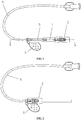
- FIG. 1 is a plan view of the disposable safe vein transfusion puncture needle in an unfolded state in this embodiment of the present invention
- FIG. 2 is a plan view of the disposable safe vein transfusion puncture needle in a retracted state in this embodiment of the present invention
- the disposable safe vein transfusion puncture needle involved in this embodiment comprises a needle head 4, a needle base 3, a needle sheath sleeved on the needle head 4, and a hose 6 communicated with the needle base 3, wherein, the needle base 3 is in a tubular shape with one end stationary and communicated with the needle head 4 and the other end connected to the hose 6.
- FIG. 3 and FIG. 4 are structural diagrams of the disposable safe vein transfusion puncture needle in a preferable embodiment of the present invention
- FIG. 5 is a sectional view along the A-A line in FIG. 1
- the disposable safe vein transfusion puncture needle involved in this embodiment further comprises a slidable component 1 movably sleeved on the needle base 3, and a slidable component 2 movably sleeved on the slidable component 1.
- Both of the slidable component 1 and the slidable component 2 are in a tubular shape with two open ends and are sleeved together.
- the innermost slidable component 1 is movably sleeved onto the needle base 3, and a sum of lengths of the slidable component 1 and the slidable component 2 in a moving direction is longer than the length of the needle head 4.
- An elastic fastener 13, an elastic fastener 21 and a groove 31, a groove 32, a groove 11, a groove 12 are provided as limiting mechanisms on the needle base 3, the slidable component 1 and the slidable component 2.
- the elastic fasteners and the grooves are adapted for engaging with each other so as to secure the slidable component 1, the slidable component 2 and the needle base 3 to one another.
- the groove 31 and the groove 32 are disposed on the needle base 3, the elastic fastener 13 is disposed on the slidable component 1, the groove 11 and the groove 12 are disposed on an exterior wall of the slidable component 1, and the elastic fastener 21 is disposed on the slidable component 2.
- the elastic fastener 13, the elastic fastener 21, and the groove 31, the groove 32, the groove 11, the groove 12 are adapted for engaging with each other when the slidable component 1 and the slidable component 2 slide to completely shield the needle head 4 or when the needle head 4 is completely exposed, so as to limit the movement of the slidable component 1 and the slidable component 2.
- An elastic locking member 14 is also provided on the slidable component 1. This elastic locking member 14 is adapted for stretching out to prevent the slidable component 2 from sliding back towards the hose 6 when the slidable component 1 and the slidable component 2 slide to completely shield the needle head 4.
- One end of the slidable component 2 close to the hose 6 has a smooth projection portion 22 circumferentially disposed thereon.
- This smooth projection portion 22 is adapted for prevent human skin from getting nipped into the gap between the slidable component 1 and the slidable component 2 when the needle head 4 is being inserted into human body.
- the projection portion 22 would press the skin of the patient during operation to make the skin slightly recessed, so that the skin adjacent to the part that touches the projection portion 22 is prevented from touching the connecting portion with gaps between the slidable component 1 and the slidable component 2 as well as between the slidable component 1 and the needle base, thereby making the skin not easy to be nipped by the gap.
- a smooth planar surface 23 is disposed on a lateral side of the slidable component 2, and the plane of the smooth planar surface 23 forms an angle of 5° with an axial line of the needle head 4.
- the slidable component 2 has a notch disposed on the lateral side with the smooth planar surface 23, and the notch is in a plane parallel to the axial line of the needle head 4, one end of the notch extends to an open end of the slidable component 2 away from the hose 6, and the other end of the notch extends to intersect with the smooth planar surface 23.
- the distance between the notch and the axial line of the needle head 4 is 0.5mm.
- the disposable safe vein transfusion puncture needle involved in this embodiment further comprises a handle 5, wherein, the slidable component 2 is provided with at least one antiskid area 24 thereon (see FIG. 4 ); the slidable component 1 and the slidable component 2 are made of elastic material, the elastic fasteners are integrally formed in one piece with the slidable component 1 and with the slidable component 2, and the groove 32 are integrally formed in one piece with the needle base 3; the handle 5 is secured to one end of the needle base 3 connected to the hose 6.
- the slidable component 1 and the slidable component 2 are sleeved on the needle base in a layered manner, which is a retracted state, and the needle head 4 is exposed, a needle sheath can be sleeved onto the needle head 4 to shield the needle head.
- the needle sheath is removed and blood transfusion is performed, and after that, in the process of pulling out the needle head 4, the slidable component 1 and the slidable component 2 slide to unfold, and are secured in an end-to-end manner by the limiting mechanisms (elastic locking member, elastic fastener, etc.) provided on the slidable component 1, on the slidable component 2 and on the needle base, so as to shield the needle head 4 and prevent the needle head from wounding the operator or the patient.
- the limiting mechanisms elastic locking member, elastic fastener, etc.
- the needle head 4 is required to be kept as close as possible to the skin of the patient, therefore, if the diameters of the slidable component 1 and the slidable component 2 are too large, such requirement cannot be met.
- the needle head 4 can be placed close to the skin in the unfolding process of the slidable component 1 and the slidable component 2.
- protrusions and annular stopper rings are provided as stopper members on the slidable component 1 and the needle base, wherein, annular stopper rings are respectively provided on an exterior wall of one end of the needle base close to the needle tip and on an exterior wall of one end of the slidable component 1 close to the needle tip, two protrusions are respectively provided on an interior wall of one end of the slidable component 1 close to the hose and on an interior wall of one end of the slidable component 2 close to the hose, so that the two protrusions on the interior walls of the first and second slidable components are clamped on the annular stopper rings after unfolding, thereby preventing the slidable component 1 or the slidable component 2 from sliding off under a pulling force after the groove is engaged with the elastic fastener.
Landscapes
- Health & Medical Sciences (AREA)
- Engineering & Computer Science (AREA)
- Life Sciences & Earth Sciences (AREA)
- Animal Behavior & Ethology (AREA)
- Public Health (AREA)
- Heart & Thoracic Surgery (AREA)
- Hematology (AREA)
- Anesthesiology (AREA)
- Veterinary Medicine (AREA)
- General Health & Medical Sciences (AREA)
- Biomedical Technology (AREA)
- Vascular Medicine (AREA)
- Environmental & Geological Engineering (AREA)
- Biophysics (AREA)
- Pulmonology (AREA)
- Infusion, Injection, And Reservoir Apparatuses (AREA)
- Finger-Pressure Massage (AREA)
Description
- The present invention relates to an intravenous needle, and in particular relates to a disposable safe vein transfusion puncture needle.
- Currently, commonly used disposable intravenous needles need to be sleeved with a needle sheath before use, so as to protect the needle head from being bent or bumped. During use, when the needle sheath is removed, a risk of puncture wound is easily caused. But the real danger is at the disposing stage after a transfusion is completed, when the needle has been pulled out from inside a body of a patient that has received transfusion, for discard disposal of the needle, the needle is put into a special disposal box or covered with a needle sheath, and as a result, a risk of puncture wound is easily caused, which might leads to serious consequences such as infection suffered by the medical staff.
- In order to deal with such defect, some intravenous needle utilizes a technical means of retractable needle, wherein, after a transfusion is completed, by using an elastic force of a structure such as a spring, the needle head retracts into a protection sheath for protecting the needle head. As such, although the needle head is effectively protected and the medical staff is prevented from being wounded by puncture, however, a great deal of pain is suffered by the patient because of the mechanical motion of the retraction of the needle head. A puncture needle is known from
US 5 573 512 andCN 1970105 with a plurality of slidable components and a plurality of limiting mechanisms - On the other hand, when the retractable needle retracts, because the retractable mechanical structure thereof usually has gaps which might nip the skin of the patient, more pain might be suffered by the patient.
- A technical problem to be solved by the present invention is that the intravenous needles of prior art have safety issue and the mechanical motion thereof causes pain suffered by the patient, so as to overcome the defects of prior art and provide a disposable safe vein transfusion puncture needle which has a better safety level and causes less pain during mechanical motion.
- The above-mentioned technical problem is solved by the following technical solution of the present invention:
- A disposable safe vein transfusion puncture needle comprising a needle head, a needle base, a needle sheath sleeved on the needle head, and a hose communicated with the needle base, wherein, the disposable safe vein transfusion puncture needle further comprises a plurality of slidable components and a plurality of limiting mechanisms, the needle base is in a tubular shape with one end stationary and communicated with the needle head and the other end connected to the hose;
- each of the slidable components is in a tubular shape and has two open ends, the plurality of slidable components are sleeved on one another, the innermost slidable component is movably sleeved onto the needle base, and a sum of lengths of the plurality of slidable components in a moving direction is longer than the length of the needle head;
- the limiting mechanisms are disposed on the plurality of slidable components as well as on the needle base and adapted for securing the innermost slidable component to the needle base as well as securing the plurality of slidable components to one another when the plurality of slidable components slide to completely shield the needle head.
- Herein, the hose is a flexible hose for transfusing blood or transfusing liquid that is commonly used in the art. That is to say, before use, a plurality of slidable components are sleeved on the needle base in a layered manner, which is a retracted state, and the needle head is exposed, a needle sheath may sleeve onto the needle head to shield the needle head. During use, the needle sheath is removed and blood transfusion is performed, and after that, in the process of pulling out the needle head, the plurality of tubular slidable components slide to unfold, and are secured in an end-to-end manner by the limiting mechanisms provided on the slidable components and on the needle base, so as to shield the needle head and prevent the needle head from wounding the operator or the patient. As such, when pulling out the needle head, it not only ensures safety, but also avoids pain caused by sudden retraction of the needle head in prior art.
- Furthermore, since the operating portion length (the length of components including the needle base and excluding the hose) of an intravenous needle is at least the length of the needle head plus the length of the needle base, and the length of the needle head is a standard length which cannot be altered, therefore, the length design of the needle base becomes the key that determines the operating portion length of an intravenous needle. In the present invention, by utilizing a structure of multiple slidable components sleeved on one another in a layered manner, in a retracted state (when the needle head is completely exposed), compared to using only one slidable component, the layered structure of multiple slidable components can significantly reduce the design length of the needle base.
- According to the invention, the disposable safe vein transfusion puncture needle comprises a first slidable component movably sleeved on the needle base, and a second slidable component movably sleeved on the first slidable component.
- Preferably, the limiting mechanisms comprise one first elastic washer, two second elastic washers, and two third elastic washers,
the first elastic washer is circumferentially attached to an interior wall of one end of the first slidable component close to the hose, and an edge of the first elastic washer is smoothly attached to the interior wall of the first slidable component;
the two second elastic washers are sleeved and attached to the needle base, the second elastic washers are adapted for engaging with the first elastic washer when the first slidable component and the second slidable component slide to completely shield the needle head or when the needle head is completely exposed, so as to limit the movement of the first slidable component;
the third elastic washers are respectively circumferentially disposed on an exterior wall of the other end of the first slidable component away from the hose as well as circumferentially attached to an interior wall of one end of the second slidable component close to the hose, the third elastic washers are adapted for engaging with each other when the first slidable component and the second slidable component slide to completely shield the needle head or when the needle head is completely exposed, so as to limit the movement of the second slidable component. - According to the invention, the limiting mechanisms comprise two elastic fasteners and four grooves, one of the elastic fasteners is disposed on the first slidable component, and the other elastic fastener is disposed on the second slidable component;
two of the grooves are disposed on the needle base, and the other two grooves are circumferentially disposed on an exterior wall of the first slidable component;
the elastic fasteners and the grooves are adapted for engaging with each other when the first slidable component and the second slidable component slide to completely shield the needle head or when the needle head is completely exposed, so as to limit the movement of the first slidable component and the second slidable component. - Preferably, the first slidable component also has an elastic locking member adapted for stretching out to prevent the second slidable component from sliding back towards the hose when the first slidable component and the second slidable component slide to completely shield the needle head.
- Herein, when the first slidable component and the second slidable component unfold, it needs to be ensured that the needle head is not exposed, so the locking steadiness between the two slidable components is directly related to the use safety of the intravenous needle. Therefore, an elastic locking member that can stretch out is provided on the exterior wall of the first slidable component. When the second slidable component has unfolded along the first slidable component to a preset position, the elastic locking member stretches out, and as a result, if the second slidable component has a tendency to slide back, the elastic locking member would push against an edge portion of the second slidable component, rendering it unable to slide back.
- According to the invention, one end of the second slidable component close to the hose has a smooth projection portion circumferentially disposed thereon. This smooth projection portion is adapted for prevent human skin from getting nipped into the gap between the first slidable component and the second slidable component when the needle head is being inserted into human body.
- Herein, because the slidable components and the needle base are sleeved by sliding, there are gaps between the slidable components as well as between the slidable component and the needle base. These gaps tend to nip the skin of the patient during operation, causing pain suffered by the patient. By providing the projection portion, the projection portion would press the skin of the patient during operation to make the skin slightly recessed, so that the skin adjacent to the part that touches the projection portion is prevented from touching the connecting portion with gaps between the first slidable component and the second slidable component as well as between the first slidable component and the needle base, thereby making the skin not easy to be nipped by the gap.
- Preferably, a smooth planar surface is disposed on a lateral side of the second slidable component, and the plane of the smooth planar surface forms an angle of 5°-20° with an axial line of the needle head.
- Preferably, the second slidable component has a notch disposed on the lateral side with the smooth planar surface, and the notch is in a plane parallel to an axial line of the needle head, one end of the notch extends to an open end of the second slidable component away from the hose, and the other end of the notch extends to intersect with the smooth planar surface.
- Herein, in the unfolding process of the first slidable component and the second slidable component, the needle head is required to be kept as close as possible to the skin of the patient, therefore, if the diameters of the first slidable component and the second slidable component are too large, such requirement cannot be met. By providing the smooth planar surface on the second slidable component, the needle head can be placed close to the skin in the unfolding process of the first slidable component and the second slidable component. By providing the notch at a position where the smooth planar surface extends close to the axial line of the needle head, the requirement of the needle head being close to the skin can be further met, thereby alleviating the pain suffered by the patient. Meanwhile, in order to prevent the needle head from accidentally wounding the operator during or after operation, the needle head should not be placed too close to the notch.
- Preferably, the notch is located at a preset distance from an axial line of the needle head.
- Preferably, the disposable safe vein transfusion puncture needle further comprises a handle, wherein, the second slidable component is provided with at least one antiskid area thereon; the slidable components are made of elastic material, the elastic fastener is integrally formed in one piece with the slidable component, and the grooves are integrally formed in one piece with the needle base;
the handle is secured to one end of the needle base connected to the hose;
the limiting mechanisms further comprise at least one stopper member disposed on the first slidable component or the needle base, adapted for preventing the second slidable component or the first slidable component from sliding off under a pulling force after the groove is engaged with the elastic fastener. - Herein, the stopper member can further prevent the slidable components and the needle base from sliding off. The stopper member may be any barrier structure, for instance, annular stopper rings are provided on an exterior wall of one end of the needle base close to the needle tip and on an exterior wall of one end of the first slidable component close to the needle tip, two protrusions are respectively provided on an interior wall of one end of the first slidable component close to the hose and on an interior wall of one end of the second slidable component close to the hose, so that the two protrusions on the interior walls of the first and second slidable components are clamped on the annular stopper rings after unfolding.
- The beneficial improvement effects of the present invention are: by providing a plurality of slidable components sleeved on the needle base in a layered manner, the operating portion length of the disposable safe vein transfusion puncture needle is made shorter, and by unfolding the slidable components layer by layer so as to shield the needle head during use and after use, the safety level is increased and the pain suffered by the patient is alleviated.
-
-
FIG. 1 is a plan view of the disposable safe vein transfusion puncture needle in an unfolded state in a preferable embodiment of the present invention. -
FIG. 2 is a plan view of the disposable safe vein transfusion puncture needle in a retracted state in a preferable embodiment of the present invention. -
FIG. 3 is a structural diagram of the disposable safe vein transfusion puncture needle in a preferable embodiment of the present invention. -
FIG. 4 is another structural diagram of the disposable safe vein transfusion puncture needle in a preferable embodiment of the present invention. -
FIG. 5 is a sectional view along the A-A line inFIG. 1 . - The present invention is further described through embodiments. However, the present invention is not thereby restricted to the scope of the described embodiments.
-
FIG. 1 is a plan view of the disposable safe vein transfusion puncture needle in an unfolded state in this embodiment of the present invention, andFIG. 2 is a plan view of the disposable safe vein transfusion puncture needle in a retracted state in this embodiment of the present invention. As shown inFIG. 1 and FIG. 2 , the disposable safe vein transfusion puncture needle involved in this embodiment comprises aneedle head 4, aneedle base 3, a needle sheath sleeved on theneedle head 4, and ahose 6 communicated with theneedle base 3, wherein, theneedle base 3 is in a tubular shape with one end stationary and communicated with theneedle head 4 and the other end connected to thehose 6. -
FIG. 3 andFIG. 4 are structural diagrams of the disposable safe vein transfusion puncture needle in a preferable embodiment of the present invention, andFIG. 5 is a sectional view along the A-A line inFIG. 1 . As shown inFIG. 3 ,FIG. 4 andFIG. 5 , the disposable safe vein transfusion puncture needle involved in this embodiment further comprises aslidable component 1 movably sleeved on theneedle base 3, and aslidable component 2 movably sleeved on theslidable component 1. - Both of the
slidable component 1 and theslidable component 2 are in a tubular shape with two open ends and are sleeved together. The innermostslidable component 1 is movably sleeved onto theneedle base 3, and a sum of lengths of theslidable component 1 and theslidable component 2 in a moving direction is longer than the length of theneedle head 4. - An
elastic fastener 13, anelastic fastener 21 and agroove 31, agroove 32, agroove 11, agroove 12 are provided as limiting mechanisms on theneedle base 3, theslidable component 1 and theslidable component 2. When theslidable component 1 and theslidable component 2 is in a unfolded state or in a retracted state, the elastic fasteners and the grooves are adapted for engaging with each other so as to secure theslidable component 1, theslidable component 2 and theneedle base 3 to one another. - Wherein, the
groove 31 and thegroove 32 are disposed on theneedle base 3, theelastic fastener 13 is disposed on theslidable component 1, thegroove 11 and thegroove 12 are disposed on an exterior wall of theslidable component 1, and theelastic fastener 21 is disposed on theslidable component 2. Theelastic fastener 13, theelastic fastener 21, and thegroove 31, thegroove 32, thegroove 11, thegroove 12 are adapted for engaging with each other when theslidable component 1 and theslidable component 2 slide to completely shield theneedle head 4 or when theneedle head 4 is completely exposed, so as to limit the movement of theslidable component 1 and theslidable component 2. - An elastic locking
member 14 is also provided on theslidable component 1. This elastic lockingmember 14 is adapted for stretching out to prevent theslidable component 2 from sliding back towards thehose 6 when theslidable component 1 and theslidable component 2 slide to completely shield theneedle head 4. - One end of the
slidable component 2 close to thehose 6 has asmooth projection portion 22 circumferentially disposed thereon. Thissmooth projection portion 22 is adapted for prevent human skin from getting nipped into the gap between theslidable component 1 and theslidable component 2 when theneedle head 4 is being inserted into human body. - Because the
slidable component 1, theslidable component 2 and theneedle base 3 are sleeved by sliding, there are gaps between theslidable component 1 and theslidable component 2 as well as between theslidable component 1 and theneedle base 3. These gaps tend to nip the skin of the patient during operation, causing pain suffered by the patient. By providing theprojection portion 22, theprojection portion 22 would press the skin of the patient during operation to make the skin slightly recessed, so that the skin adjacent to the part that touches theprojection portion 22 is prevented from touching the connecting portion with gaps between theslidable component 1 and theslidable component 2 as well as between theslidable component 1 and the needle base, thereby making the skin not easy to be nipped by the gap. - A smooth
planar surface 23 is disposed on a lateral side of theslidable component 2, and the plane of the smoothplanar surface 23 forms an angle of 5° with an axial line of theneedle head 4. Theslidable component 2 has a notch disposed on the lateral side with the smoothplanar surface 23, and the notch is in a plane parallel to the axial line of theneedle head 4, one end of the notch extends to an open end of theslidable component 2 away from thehose 6, and the other end of the notch extends to intersect with the smoothplanar surface 23. The distance between the notch and the axial line of theneedle head 4 is 0.5mm. - The disposable safe vein transfusion puncture needle involved in this embodiment further comprises a
handle 5, wherein, theslidable component 2 is provided with at least oneantiskid area 24 thereon (seeFIG. 4 ); theslidable component 1 and theslidable component 2 are made of elastic material, the elastic fasteners are integrally formed in one piece with theslidable component 1 and with theslidable component 2, and thegroove 32 are integrally formed in one piece with theneedle base 3; thehandle 5 is secured to one end of theneedle base 3 connected to thehose 6. - Before use, the
slidable component 1 and theslidable component 2 are sleeved on the needle base in a layered manner, which is a retracted state, and theneedle head 4 is exposed, a needle sheath can be sleeved onto theneedle head 4 to shield the needle head. During use, the needle sheath is removed and blood transfusion is performed, and after that, in the process of pulling out theneedle head 4, theslidable component 1 and theslidable component 2 slide to unfold, and are secured in an end-to-end manner by the limiting mechanisms (elastic locking member, elastic fastener, etc.) provided on theslidable component 1, on theslidable component 2 and on the needle base, so as to shield theneedle head 4 and prevent the needle head from wounding the operator or the patient. As such, when pulling out the needle head, it not only ensures safety, but also avoids pain caused by sudden retraction of the needle head in prior art. - Furthermore, in the unfolding process of the
slidable component 1 and theslidable component 2, theneedle head 4 is required to be kept as close as possible to the skin of the patient, therefore, if the diameters of theslidable component 1 and theslidable component 2 are too large, such requirement cannot be met. By providing the smoothplanar surface 23 on theslidable component 2, theneedle head 4 can be placed close to the skin in the unfolding process of theslidable component 1 and theslidable component 2. By providing the notch at a position where the smoothplanar surface 23 extends close to the axial line of the needle head, the requirement of the needle head being close to the skin can be further met, thereby alleviating the pain suffered by the patient. - Furthermore, protrusions and annular stopper rings (not shown in the Figures) are provided as stopper members on the
slidable component 1 and the needle base, wherein, annular stopper rings are respectively provided on an exterior wall of one end of the needle base close to the needle tip and on an exterior wall of one end of theslidable component 1 close to the needle tip, two protrusions are respectively provided on an interior wall of one end of theslidable component 1 close to the hose and on an interior wall of one end of theslidable component 2 close to the hose, so that the two protrusions on the interior walls of the first and second slidable components are clamped on the annular stopper rings after unfolding, thereby preventing theslidable component 1 or theslidable component 2 from sliding off under a pulling force after the groove is engaged with the elastic fastener. - Although specific embodiments of the present invention are described above, those skilled in the art should understand, this is only illustration, and the protection scope of the present invention is defined by the appended Claims. On the premise of not deviating from the principle and essence of the present invention as defined by the appended Claims, those skilled in the art can make various changes and modifications to these implementing embodiments. For example, the buckle structure such as the elastic fasteners and grooves may not be used, and instead the slidable components may be secured on the needle base by mutual clamping of elastic washers. These changes and modifications are all embraced within the protection scope of the present invention.
Claims (6)
- A disposable safe vein transfusion puncture needle, comprisinga needle head (4),a needle base (3),a needle sheath, sleeved on the needle head (4); anda hose (6), communicated with the needle base (3),a plurality of slidable components (1, 2); anda plurality of limiting mechanisms,wherein,the needle base (3) is in a tubular shape, with one end stationary and communicated with the needle head (4) and the other end connected to the hose (6);each of the slidable components (1, 2) is in a tubular shape and has two open ends, the plurality of slidable components (1, 2) are sleeved on one another, the innermost slidable component (1) is movably sleeved onto the needle base (3), and a sum of lengths of the plurality of slidable components (1, 2) in a moving direction is longer than the length of the needle head (4);the limiting mechanisms are disposed on the plurality of slidable components (1, 2) as well as on the needle base (3) and adapted for securing the innermost slidable component (1) to the needle base (3) as well as securing the plurality of slidable components (1, 2) to one another when the plurality of slidable components (1, 2) slide to completely shield the needle head (4),the disposable safe vein transfusion puncture needle comprises a first slidable component (1) movably sleeved on the needle base (3) and a second slidable component (2) movably sleeved on the first slidable component (1),characterized in that the limiting mechanisms comprise two elastic fasteners (13, 21) and four grooves (31, 32, 11, 12), one of the elastic fasteners (13) is disposed on the first slidable component (1), and the other elastic fastener (21) is disposed on the second slidable component (2); two of the grooves (31, 32) are disposed on the needle base (3), and the other two grooves (11, 12) are circumferentially disposed on an exterior wall of the first slidable component (1); the elastic fasteners (13, 21) and the grooves (31, 32, 11, 12) are adapted for engaging with each other when the first slidable component (1) and the second slidable component (2) slide to completely shield the needle head (4) or when the needle head (4) is completely exposed, so as to limit the movement of the first slidable component (1) and the second slidable component (2),one end of the second slidable component (2) close to the hose (6) has a smooth projection portion (22) circumferentially disposed thereon.
- The disposable safe vein transfusion puncture needle in accordance with Claim 1, characterized in that, the first slidable component (1) also has an elastic locking member (14) adapted for stretching out to prevent the second slidable component (2) from sliding back towards the hose (6) when the first slidable component (1) and the second slidable component (2) slide to completely shield the needle head (4).
- The disposable safe vein transfusion puncture needle in accordance with Claim 1, characterized in that, a smooth planar surface (23) is disposed on a lateral side of the second slidable component (2), and the plane of the smooth planar surface (23) forms an angle of 5°-20° with an axial line of the needle head (4).
- The disposable safe vein transfusion puncture needle in accordance with Claim 3, characterized in that,the second slidable component (2) has a notch disposed on the lateral side with the smooth planar surface (23), and the notch is in a plane parallel to an axial line of the needle head,one end of the notch extends to an open end of the second slidable component (2) away from the hose (6), and the other end of the notch extends to intersect with the smooth planar surface (23).
- The disposable safe vein transfusion puncture needle in accordance with Claim 4, characterized in that, the notch is located at a preset distance from an axial line of the needle head (4).
- The disposable safe vein transfusion puncture needle in accordance with any one of Claims 1-5, characterized in further comprising a handle (5), wherein, the second slidable component is provided with at least one antiskid area (24) thereon;the slidable components (1, 2) are made of elastic material, the elastic fastener (13, 21) is integrally formed in one piece with the slidable component (1, 2), and the grooves (31, 32, 11, 12) are integrally formed in one piece with the needle base (3);the handle (5) is secured to one end of the needle base (3) connected to the hose (6);the limiting mechanisms further comprise at least one stopper member disposed on the first slidable component (1) or the needle base (3), adapted for preventing the second slidable component (2) or the first slidable component (1) from sliding off under a pulling force after the groove is engaged with the elastic fastener (13, 21).
Applications Claiming Priority (3)
| Application Number | Priority Date | Filing Date | Title |
|---|---|---|---|
| CN201410577644.7A CN104288866B (en) | 2014-10-24 | 2014-10-24 | The anti-acupuncture venous transfusion puncturing needle of single use |
| CN201420621938.0U CN204181959U (en) | 2014-10-24 | 2014-10-24 | The anti-acupuncture venous transfusion puncturing needle of single use |
| PCT/CN2015/075658 WO2016062016A1 (en) | 2014-10-24 | 2015-04-01 | Disposable anti-acupuncture intravenous infusion puncture needle |
Publications (3)
| Publication Number | Publication Date |
|---|---|
| EP3093034A1 EP3093034A1 (en) | 2016-11-16 |
| EP3093034A4 EP3093034A4 (en) | 2017-08-30 |
| EP3093034B1 true EP3093034B1 (en) | 2019-12-18 |
Family
ID=55760179
Family Applications (1)
| Application Number | Title | Priority Date | Filing Date |
|---|---|---|---|
| EP15851761.5A Active EP3093034B1 (en) | 2014-10-24 | 2015-04-01 | Disposable anti-acupuncture intravenous infusion puncture needle |
Country Status (16)
| Country | Link |
|---|---|
| US (1) | US10188803B2 (en) |
| EP (1) | EP3093034B1 (en) |
| JP (1) | JP6286063B2 (en) |
| KR (1) | KR101893804B1 (en) |
| AU (1) | AU2015336700B2 (en) |
| BR (1) | BR112016021855B1 (en) |
| CA (1) | CA2943156C (en) |
| EA (1) | EA032213B1 (en) |
| ES (1) | ES2777309T3 (en) |
| MX (1) | MX374132B (en) |
| MY (1) | MY171366A (en) |
| PH (1) | PH12016501857A1 (en) |
| PT (1) | PT3093034T (en) |
| SA (1) | SA516380089B1 (en) |
| SG (1) | SG11201607162QA (en) |
| WO (1) | WO2016062016A1 (en) |
Families Citing this family (30)
| Publication number | Priority date | Publication date | Assignee | Title |
|---|---|---|---|---|
| US10172611B2 (en) | 2014-06-10 | 2019-01-08 | Ethicon Llc | Adjunct materials and methods of using same in surgical methods for tissue sealing |
| US11566082B2 (en) | 2014-11-17 | 2023-01-31 | Cytiva Bioprocess R&D Ab | Mutated immunoglobulin-binding polypeptides |
| US10639455B2 (en) | 2015-10-28 | 2020-05-05 | Becton, Dickinson And Company | Closed IV access device with paddle grip needle hub and flash chamber |
| US10245416B2 (en) | 2015-10-28 | 2019-04-02 | Becton, Dickinson And Company | Intravenous catheter device with integrated extension tube |
| US10549072B2 (en) | 2015-10-28 | 2020-02-04 | Becton, Dickinson And Company | Integrated catheter with independent fluid paths |
| US10814106B2 (en) | 2015-10-28 | 2020-10-27 | Becton, Dickinson And Company | Soft push tabs for catheter adapter |
| US10357636B2 (en) | 2015-10-28 | 2019-07-23 | Becton, Dickinson And Company | IV access device having an angled paddle grip |
| US10744305B2 (en) | 2015-10-28 | 2020-08-18 | Becton, Dickinson And Company | Ergonomic IV systems and methods |
| US10525237B2 (en) | 2015-10-28 | 2020-01-07 | Becton, Dickinson And Company | Ergonomic IV systems and methods |
| BR112017020577B1 (en) | 2015-11-23 | 2022-12-13 | Gemtier Medical (Shanghai) Inc | NEEDLE DEVICE |
| JP6336008B2 (en) | 2015-11-23 | 2018-06-06 | ジェムティア メディカル (シャンハイ) インコーポレイテッド | Needle stick device |
| US10889615B2 (en) | 2016-05-11 | 2021-01-12 | Cytiva Bioprocess R&D Ab | Mutated immunoglobulin-binding polypeptides |
| JP6987424B2 (en) | 2016-05-11 | 2022-01-05 | サイティバ・バイオプロセス・アールアンドディ・アクチボラグ | How to clean and / or disinfect the isolation matrix |
| US11708390B2 (en) | 2016-05-11 | 2023-07-25 | Cytiva Bioprocess R&D Ab | Method of storing a separation matrix |
| USD835262S1 (en) * | 2016-10-05 | 2018-12-04 | Becton, Dickinson And Company | Intravenous catheter assembly |
| USD819802S1 (en) * | 2016-10-05 | 2018-06-05 | Becton, Dickinson And Company | Catheter adapter |
| US10238852B2 (en) | 2016-10-05 | 2019-03-26 | Becton, Dickinson And Company | Septum housing |
| USD837368S1 (en) * | 2016-10-05 | 2019-01-01 | Becton, Dickinson And Company | Catheter adapter grip |
| USD844781S1 (en) * | 2016-10-05 | 2019-04-02 | Becton, Dickinson And Company | Needle hub |
| JP7362626B2 (en) | 2018-02-21 | 2023-10-17 | エシコン エルエルシー | knitted tissue scaffold |
| USD885574S1 (en) | 2018-02-21 | 2020-05-26 | Ethicon Llc | Knitted tissue scaffold |
| BR112020016970A2 (en) * | 2018-02-21 | 2020-12-15 | Ethicon Llc | KNITTED FRAMES FOR FABRIC |
| US20190254669A1 (en) | 2018-02-21 | 2019-08-22 | Ethicon Llc | Knitted tissue scaffolds |
| CN109316648A (en) * | 2018-09-13 | 2019-02-12 | 符霞军 | A kind of disposable transfusion device being automatically turned off |
| CN111888588B (en) * | 2020-07-24 | 2024-12-27 | 贝普医疗科技股份有限公司 | A needle-puncture prevention device with a spring and a stopper |
| US11707279B2 (en) | 2020-11-25 | 2023-07-25 | Cilag Gmbh International | Compressible knitted adjuncts with finished edges |
| US11446027B2 (en) | 2020-11-25 | 2022-09-20 | Cilag Gmbh International | Compressible knitted adjuncts with surface features |
| US11690617B2 (en) | 2020-11-25 | 2023-07-04 | Cilag Gmbh International | Compressible knitted adjuncts with finished edges |
| US11678883B2 (en) | 2020-11-25 | 2023-06-20 | Cilag Gmbh International | Compressible knitted adjuncts with varying interconnections |
| US11648007B2 (en) | 2020-11-25 | 2023-05-16 | Cilag Gmbh International | Compressible knitted adjuncts with varying fiber features |
Family Cites Families (23)
| Publication number | Priority date | Publication date | Assignee | Title |
|---|---|---|---|---|
| US4804372A (en) * | 1987-09-08 | 1989-02-14 | Laico Joseph P | Protective sheath for hypodermic needle |
| CA1337167C (en) * | 1989-03-14 | 1995-10-03 | Eastman Kodak Company | Needle housing with retractable needle |
| NL9002552A (en) * | 1990-09-05 | 1992-04-01 | Advanced Protective Injection | INFUSION OR TRANSFUSION NEEDLE ASSEMBLY. |
| JP2672062B2 (en) | 1993-01-20 | 1997-11-05 | ベクトン・ディッキンソン・アンド・カンパニー | IV injection or blood collection assembly |
| JP4383572B2 (en) * | 1999-03-05 | 2009-12-16 | メディキット株式会社 | Safety indwelling needle |
| JP2001259029A (en) * | 2000-03-21 | 2001-09-25 | Medikit Kk | Safe indwelling needle |
| US6723037B2 (en) * | 2000-12-15 | 2004-04-20 | Kawasumi Laboratories, Inc. | Protective tool for therapeutic material delivery device, cartridge for therapeutic material delivery device, and a therapeutic material delivery device |
| JP2003164525A (en) * | 2001-12-04 | 2003-06-10 | Tasuku:Kk | Injection needle safety device |
| US7060053B2 (en) | 2002-02-28 | 2006-06-13 | Medikit Co., Ltd. | Safety indwelling syringe |
| US6623461B1 (en) * | 2002-03-15 | 2003-09-23 | Becton, Dickinson And Company | Forward shielding safety device |
| US20040176730A1 (en) | 2002-08-13 | 2004-09-09 | Wang Hsien Tsung | Disposable, safe butterfly needle sheath |
| CN2803403Y (en) * | 2005-04-25 | 2006-08-09 | 林宇岳 | Infusion set needle safety device |
| JP4654102B2 (en) | 2005-09-29 | 2011-03-16 | テルモ株式会社 | Protector and needle set |
| CN1970105A (en) * | 2005-11-22 | 2007-05-30 | 杨章民 | One-time safety intravenous indwelling needle |
| KR100800426B1 (en) * | 2007-03-14 | 2008-02-01 | 단국대학교 산학협력단 | Dental needle with safety cover |
| JP5213950B2 (en) | 2007-04-23 | 2013-06-19 | エス・アイ・ディ・テクノロジーズ・リミテッド・ライアビリティ・カンパニー | Method and apparatus for intradermal injection |
| CN100563742C (en) * | 2007-06-06 | 2009-12-02 | 邱晓菲 | Disposable stab-proof injection needles |
| ES2575546T3 (en) * | 2010-03-12 | 2016-06-29 | Sid Technologies Llc | Set for use with a syringe |
| BR112016010016B1 (en) | 2014-04-11 | 2022-05-03 | Shanghai Jinta Medical Co.Ltd | SAFETY BLOOD COLLECTION NEEDLE |
| CN103977475B (en) * | 2014-04-11 | 2016-08-17 | 上海金塔医用器材有限公司 | Safe vein pin |
| CN104288866B (en) * | 2014-10-24 | 2015-07-29 | 上海金塔医用器材有限公司 | The anti-acupuncture venous transfusion puncturing needle of single use |
| CN204181959U (en) | 2014-10-24 | 2015-03-04 | 上海金塔医用器材有限公司 | The anti-acupuncture venous transfusion puncturing needle of single use |
| KR20170019187A (en) * | 2015-08-11 | 2017-02-21 | 주식회사 세이퍼위드 | Syringe assembly |
-
2015
- 2015-04-01 BR BR112016021855-8A patent/BR112016021855B1/en active IP Right Grant
- 2015-04-01 WO PCT/CN2015/075658 patent/WO2016062016A1/en not_active Ceased
- 2015-04-01 AU AU2015336700A patent/AU2015336700B2/en active Active
- 2015-04-01 MX MX2016012572A patent/MX374132B/en active IP Right Grant
- 2015-04-01 PT PT158517615T patent/PT3093034T/en unknown
- 2015-04-01 EP EP15851761.5A patent/EP3093034B1/en active Active
- 2015-04-01 CA CA2943156A patent/CA2943156C/en active Active
- 2015-04-01 JP JP2016562951A patent/JP6286063B2/en active Active
- 2015-04-01 EA EA201691849A patent/EA032213B1/en not_active IP Right Cessation
- 2015-04-01 SG SG11201607162QA patent/SG11201607162QA/en unknown
- 2015-04-01 ES ES15851761T patent/ES2777309T3/en active Active
- 2015-04-01 KR KR1020167022824A patent/KR101893804B1/en active Active
- 2015-04-01 US US15/312,581 patent/US10188803B2/en active Active
- 2015-04-01 MY MYPI2016703477A patent/MY171366A/en unknown
-
2016
- 2016-09-22 PH PH12016501857A patent/PH12016501857A1/en unknown
- 2016-10-16 SA SA516380089A patent/SA516380089B1/en unknown
Non-Patent Citations (1)
| Title |
|---|
| None * |
Also Published As
| Publication number | Publication date |
|---|---|
| SA516380089B1 (en) | 2019-12-24 |
| KR101893804B1 (en) | 2018-08-31 |
| BR112016021855A2 (en) | 2020-06-30 |
| MY171366A (en) | 2019-10-10 |
| CA2943156A1 (en) | 2016-04-28 |
| PT3093034T (en) | 2020-03-25 |
| EA201691849A1 (en) | 2017-01-30 |
| AU2015336700A1 (en) | 2016-08-25 |
| MX2016012572A (en) | 2016-12-14 |
| CA2943156C (en) | 2017-10-17 |
| EA032213B1 (en) | 2019-04-30 |
| JP6286063B2 (en) | 2018-02-28 |
| PH12016501857A1 (en) | 2016-12-19 |
| EP3093034A1 (en) | 2016-11-16 |
| WO2016062016A1 (en) | 2016-04-28 |
| US10188803B2 (en) | 2019-01-29 |
| JP2017525397A (en) | 2017-09-07 |
| US20170216535A1 (en) | 2017-08-03 |
| MX374132B (en) | 2025-03-05 |
| BR112016021855B1 (en) | 2022-06-14 |
| KR20160150291A (en) | 2016-12-29 |
| SG11201607162QA (en) | 2016-10-28 |
| ES2777309T3 (en) | 2020-08-04 |
| AU2015336700B2 (en) | 2017-01-05 |
| EP3093034A4 (en) | 2017-08-30 |
Similar Documents
| Publication | Publication Date | Title |
|---|---|---|
| EP3093034B1 (en) | Disposable anti-acupuncture intravenous infusion puncture needle | |
| CN104288866B (en) | The anti-acupuncture venous transfusion puncturing needle of single use | |
| EP2985049B1 (en) | Butterfly-type needle assembly and butterfly-type needle protective sleeve | |
| JP6169794B2 (en) | Safety blood collection needle | |
| WO2016062015A1 (en) | Disposable anti-acupuncture venous transfusion needle | |
| TW201806633A (en) | An anti-acupuncture structure and an anti-acupuncture intravenous infusion puncture needle | |
| WO2016107028A1 (en) | Anti-needlestick two-wing venipuncture needle | |
| CN204411424U (en) | Anti-acupuncture syringe | |
| CN103977475B (en) | Safe vein pin | |
| CN204181958U (en) | The anti-acupuncture venoclysis needle of single use | |
| CN105816189A (en) | Anti-needling safety blood taking needle | |
| JP7444785B2 (en) | Needle device and blood collection set | |
| CN105816936B (en) | Anti-acupuncture double-wing vein puncture needle | |
| WO2016107029A1 (en) | Anti-needlestick syringe | |
| CN203829413U (en) | Safe vein needle | |
| CN107754048A (en) | Anti- needling structure and anti-acupuncture venous transfusion puncturing needle | |
| CN104188669B (en) | The anti-aculeus blood-taking pin of disposable use | |
| TWM513032U (en) | Safety protection device for syringe | |
| TWM504607U (en) | Safety protector of butterfly needle | |
| TWI583417B (en) | Butterfly pin safety protection device | |
| WO2016015364A1 (en) | Safe blood sampling needle | |
| HK1221140B (en) | Safety blood-collection needle | |
| ITPD20080275A1 (en) | ASSEMBLY OF HYPODERMIC NEEDLE WITH SAFETY DEVICE. | |
| TW201639604A (en) | Safety protection apparatus for injection syringe |
Legal Events
| Date | Code | Title | Description |
|---|---|---|---|
| PUAI | Public reference made under article 153(3) epc to a published international application that has entered the european phase |
Free format text: ORIGINAL CODE: 0009012 |
|
| 17P | Request for examination filed |
Effective date: 20160811 |
|
| AK | Designated contracting states |
Kind code of ref document: A1 Designated state(s): AL AT BE BG CH CY CZ DE DK EE ES FI FR GB GR HR HU IE IS IT LI LT LU LV MC MK MT NL NO PL PT RO RS SE SI SK SM TR |
|
| AX | Request for extension of the european patent |
Extension state: BA ME |
|
| A4 | Supplementary search report drawn up and despatched |
Effective date: 20170727 |
|
| RIC1 | Information provided on ipc code assigned before grant |
Ipc: A61M 25/06 20060101ALI20170721BHEP Ipc: A61M 5/158 20060101AFI20170721BHEP |
|
| DAV | Request for validation of the european patent (deleted) | ||
| DAX | Request for extension of the european patent (deleted) | ||
| GRAP | Despatch of communication of intention to grant a patent |
Free format text: ORIGINAL CODE: EPIDOSNIGR1 |
|
| STAA | Information on the status of an ep patent application or granted ep patent |
Free format text: STATUS: GRANT OF PATENT IS INTENDED |
|
| INTG | Intention to grant announced |
Effective date: 20190711 |
|
| GRAS | Grant fee paid |
Free format text: ORIGINAL CODE: EPIDOSNIGR3 |
|
| GRAA | (expected) grant |
Free format text: ORIGINAL CODE: 0009210 |
|
| STAA | Information on the status of an ep patent application or granted ep patent |
Free format text: STATUS: THE PATENT HAS BEEN GRANTED |
|
| AK | Designated contracting states |
Kind code of ref document: B1 Designated state(s): AL AT BE BG CH CY CZ DE DK EE ES FI FR GB GR HR HU IE IS IT LI LT LU LV MC MK MT NL NO PL PT RO RS SE SI SK SM TR |
|
| REG | Reference to a national code |
Ref country code: CH Ref legal event code: EP |
|
| REG | Reference to a national code |
Ref country code: IE Ref legal event code: FG4D |
|
| REG | Reference to a national code |
Ref country code: DE Ref legal event code: R096 Ref document number: 602015044049 Country of ref document: DE |
|
| REG | Reference to a national code |
Ref country code: AT Ref legal event code: REF Ref document number: 1213879 Country of ref document: AT Kind code of ref document: T Effective date: 20200115 |
|
| REG | Reference to a national code |
Ref country code: CH Ref legal event code: NV Representative=s name: OFFICE ERNEST T. FREYLINGER S.A., CH |
|
| REG | Reference to a national code |
Ref country code: PT Ref legal event code: SC4A Ref document number: 3093034 Country of ref document: PT Date of ref document: 20200325 Kind code of ref document: T Free format text: AVAILABILITY OF NATIONAL TRANSLATION Effective date: 20200312 |
|
| REG | Reference to a national code |
Ref country code: NL Ref legal event code: MP Effective date: 20191218 |
|
| PG25 | Lapsed in a contracting state [announced via postgrant information from national office to epo] |
Ref country code: LT Free format text: LAPSE BECAUSE OF FAILURE TO SUBMIT A TRANSLATION OF THE DESCRIPTION OR TO PAY THE FEE WITHIN THE PRESCRIBED TIME-LIMIT Effective date: 20191218 Ref country code: LV Free format text: LAPSE BECAUSE OF FAILURE TO SUBMIT A TRANSLATION OF THE DESCRIPTION OR TO PAY THE FEE WITHIN THE PRESCRIBED TIME-LIMIT Effective date: 20191218 Ref country code: SE Free format text: LAPSE BECAUSE OF FAILURE TO SUBMIT A TRANSLATION OF THE DESCRIPTION OR TO PAY THE FEE WITHIN THE PRESCRIBED TIME-LIMIT Effective date: 20191218 Ref country code: BG Free format text: LAPSE BECAUSE OF FAILURE TO SUBMIT A TRANSLATION OF THE DESCRIPTION OR TO PAY THE FEE WITHIN THE PRESCRIBED TIME-LIMIT Effective date: 20200318 Ref country code: FI Free format text: LAPSE BECAUSE OF FAILURE TO SUBMIT A TRANSLATION OF THE DESCRIPTION OR TO PAY THE FEE WITHIN THE PRESCRIBED TIME-LIMIT Effective date: 20191218 Ref country code: NO Free format text: LAPSE BECAUSE OF FAILURE TO SUBMIT A TRANSLATION OF THE DESCRIPTION OR TO PAY THE FEE WITHIN THE PRESCRIBED TIME-LIMIT Effective date: 20200318 |
|
| REG | Reference to a national code |
Ref country code: LT Ref legal event code: MG4D |
|
| REG | Reference to a national code |
Ref country code: GR Ref legal event code: EP Ref document number: 20200400784 Country of ref document: GR Effective date: 20200518 |
|
| PG25 | Lapsed in a contracting state [announced via postgrant information from national office to epo] |
Ref country code: RS Free format text: LAPSE BECAUSE OF FAILURE TO SUBMIT A TRANSLATION OF THE DESCRIPTION OR TO PAY THE FEE WITHIN THE PRESCRIBED TIME-LIMIT Effective date: 20191218 Ref country code: HR Free format text: LAPSE BECAUSE OF FAILURE TO SUBMIT A TRANSLATION OF THE DESCRIPTION OR TO PAY THE FEE WITHIN THE PRESCRIBED TIME-LIMIT Effective date: 20191218 |
|
| PG25 | Lapsed in a contracting state [announced via postgrant information from national office to epo] |
Ref country code: AL Free format text: LAPSE BECAUSE OF FAILURE TO SUBMIT A TRANSLATION OF THE DESCRIPTION OR TO PAY THE FEE WITHIN THE PRESCRIBED TIME-LIMIT Effective date: 20191218 |
|
| PG25 | Lapsed in a contracting state [announced via postgrant information from national office to epo] |
Ref country code: RO Free format text: LAPSE BECAUSE OF FAILURE TO SUBMIT A TRANSLATION OF THE DESCRIPTION OR TO PAY THE FEE WITHIN THE PRESCRIBED TIME-LIMIT Effective date: 20191218 Ref country code: CZ Free format text: LAPSE BECAUSE OF FAILURE TO SUBMIT A TRANSLATION OF THE DESCRIPTION OR TO PAY THE FEE WITHIN THE PRESCRIBED TIME-LIMIT Effective date: 20191218 Ref country code: NL Free format text: LAPSE BECAUSE OF FAILURE TO SUBMIT A TRANSLATION OF THE DESCRIPTION OR TO PAY THE FEE WITHIN THE PRESCRIBED TIME-LIMIT Effective date: 20191218 Ref country code: EE Free format text: LAPSE BECAUSE OF FAILURE TO SUBMIT A TRANSLATION OF THE DESCRIPTION OR TO PAY THE FEE WITHIN THE PRESCRIBED TIME-LIMIT Effective date: 20191218 |
|
| REG | Reference to a national code |
Ref country code: ES Ref legal event code: FG2A Ref document number: 2777309 Country of ref document: ES Kind code of ref document: T3 Effective date: 20200804 |
|
| PG25 | Lapsed in a contracting state [announced via postgrant information from national office to epo] |
Ref country code: IS Free format text: LAPSE BECAUSE OF FAILURE TO SUBMIT A TRANSLATION OF THE DESCRIPTION OR TO PAY THE FEE WITHIN THE PRESCRIBED TIME-LIMIT Effective date: 20200418 Ref country code: SM Free format text: LAPSE BECAUSE OF FAILURE TO SUBMIT A TRANSLATION OF THE DESCRIPTION OR TO PAY THE FEE WITHIN THE PRESCRIBED TIME-LIMIT Effective date: 20191218 Ref country code: SK Free format text: LAPSE BECAUSE OF FAILURE TO SUBMIT A TRANSLATION OF THE DESCRIPTION OR TO PAY THE FEE WITHIN THE PRESCRIBED TIME-LIMIT Effective date: 20191218 |
|
| REG | Reference to a national code |
Ref country code: DE Ref legal event code: R097 Ref document number: 602015044049 Country of ref document: DE |
|
| REG | Reference to a national code |
Ref country code: AT Ref legal event code: MK05 Ref document number: 1213879 Country of ref document: AT Kind code of ref document: T Effective date: 20191218 |
|
| PLBE | No opposition filed within time limit |
Free format text: ORIGINAL CODE: 0009261 |
|
| STAA | Information on the status of an ep patent application or granted ep patent |
Free format text: STATUS: NO OPPOSITION FILED WITHIN TIME LIMIT |
|
| PG25 | Lapsed in a contracting state [announced via postgrant information from national office to epo] |
Ref country code: DK Free format text: LAPSE BECAUSE OF FAILURE TO SUBMIT A TRANSLATION OF THE DESCRIPTION OR TO PAY THE FEE WITHIN THE PRESCRIBED TIME-LIMIT Effective date: 20191218 |
|
| 26N | No opposition filed |
Effective date: 20200921 |
|
| PG25 | Lapsed in a contracting state [announced via postgrant information from national office to epo] |
Ref country code: AT Free format text: LAPSE BECAUSE OF FAILURE TO SUBMIT A TRANSLATION OF THE DESCRIPTION OR TO PAY THE FEE WITHIN THE PRESCRIBED TIME-LIMIT Effective date: 20191218 Ref country code: SI Free format text: LAPSE BECAUSE OF FAILURE TO SUBMIT A TRANSLATION OF THE DESCRIPTION OR TO PAY THE FEE WITHIN THE PRESCRIBED TIME-LIMIT Effective date: 20191218 |
|
| REG | Reference to a national code |
Ref country code: BE Ref legal event code: MM Effective date: 20200430 |
|
| PG25 | Lapsed in a contracting state [announced via postgrant information from national office to epo] |
Ref country code: BE Free format text: LAPSE BECAUSE OF NON-PAYMENT OF DUE FEES Effective date: 20200430 Ref country code: PL Free format text: LAPSE BECAUSE OF FAILURE TO SUBMIT A TRANSLATION OF THE DESCRIPTION OR TO PAY THE FEE WITHIN THE PRESCRIBED TIME-LIMIT Effective date: 20191218 |
|
| PG25 | Lapsed in a contracting state [announced via postgrant information from national office to epo] |
Ref country code: CY Free format text: LAPSE BECAUSE OF FAILURE TO SUBMIT A TRANSLATION OF THE DESCRIPTION OR TO PAY THE FEE WITHIN THE PRESCRIBED TIME-LIMIT Effective date: 20191218 |
|
| PG25 | Lapsed in a contracting state [announced via postgrant information from national office to epo] |
Ref country code: MK Free format text: LAPSE BECAUSE OF FAILURE TO SUBMIT A TRANSLATION OF THE DESCRIPTION OR TO PAY THE FEE WITHIN THE PRESCRIBED TIME-LIMIT Effective date: 20191218 |
|
| PG25 | Lapsed in a contracting state [announced via postgrant information from national office to epo] |
Ref country code: IT Free format text: LAPSE BECAUSE OF NON-PAYMENT OF DUE FEES Effective date: 20220401 |
|
| PGFP | Annual fee paid to national office [announced via postgrant information from national office to epo] |
Ref country code: MC Payment date: 20250324 Year of fee payment: 11 |
|
| PGFP | Annual fee paid to national office [announced via postgrant information from national office to epo] |
Ref country code: PT Payment date: 20250319 Year of fee payment: 11 |
|
| PGFP | Annual fee paid to national office [announced via postgrant information from national office to epo] |
Ref country code: LU Payment date: 20250324 Year of fee payment: 11 |
|
| PGFP | Annual fee paid to national office [announced via postgrant information from national office to epo] |
Ref country code: IE Payment date: 20250320 Year of fee payment: 11 |
|
| PGFP | Annual fee paid to national office [announced via postgrant information from national office to epo] |
Ref country code: GR Payment date: 20250318 Year of fee payment: 11 |
|
| PGFP | Annual fee paid to national office [announced via postgrant information from national office to epo] |
Ref country code: TR Payment date: 20250328 Year of fee payment: 11 |
|
| PGFP | Annual fee paid to national office [announced via postgrant information from national office to epo] |
Ref country code: DE Payment date: 20250411 Year of fee payment: 11 |
|
| PGFP | Annual fee paid to national office [announced via postgrant information from national office to epo] |
Ref country code: GB Payment date: 20250417 Year of fee payment: 11 Ref country code: ES Payment date: 20250512 Year of fee payment: 11 |
|
| PGFP | Annual fee paid to national office [announced via postgrant information from national office to epo] |
Ref country code: IT Payment date: 20250409 Year of fee payment: 11 |
|
| PGFP | Annual fee paid to national office [announced via postgrant information from national office to epo] |
Ref country code: FR Payment date: 20250429 Year of fee payment: 11 |
|
| PGFP | Annual fee paid to national office [announced via postgrant information from national office to epo] |
Ref country code: MT Payment date: 20250402 Year of fee payment: 11 |
|
| PGFP | Annual fee paid to national office [announced via postgrant information from national office to epo] |
Ref country code: CH Payment date: 20250501 Year of fee payment: 11 |
|
| PG25 | Lapsed in a contracting state [announced via postgrant information from national office to epo] |
Ref country code: IT Free format text: LAPSE BECAUSE OF NON-PAYMENT OF DUE FEES Effective date: 20220401 |
|
| PGRI | Patent reinstated in contracting state [announced from national office to epo] |
Ref country code: IT Effective date: 20230707 |