EP3027331B1 - Casting and rolling plant and method for producing slabs - Google Patents
Casting and rolling plant and method for producing slabs Download PDFInfo
- Publication number
- EP3027331B1 EP3027331B1 EP14747587.5A EP14747587A EP3027331B1 EP 3027331 B1 EP3027331 B1 EP 3027331B1 EP 14747587 A EP14747587 A EP 14747587A EP 3027331 B1 EP3027331 B1 EP 3027331B1
- Authority
- EP
- European Patent Office
- Prior art keywords
- casting
- strip
- rolling mill
- slabs
- steckel
- Prior art date
- Legal status (The legal status is an assumption and is not a legal conclusion. Google has not performed a legal analysis and makes no representation as to the accuracy of the status listed.)
- Active
Links
Images
Classifications
-
- B—PERFORMING OPERATIONS; TRANSPORTING
- B21—MECHANICAL METAL-WORKING WITHOUT ESSENTIALLY REMOVING MATERIAL; PUNCHING METAL
- B21B—ROLLING OF METAL
- B21B1/00—Metal-rolling methods or mills for making semi-finished products of solid or profiled cross-section; Sequence of operations in milling trains; Layout of rolling-mill plant, e.g. grouping of stands; Succession of passes or of sectional pass alternations
- B21B1/46—Metal-rolling methods or mills for making semi-finished products of solid or profiled cross-section; Sequence of operations in milling trains; Layout of rolling-mill plant, e.g. grouping of stands; Succession of passes or of sectional pass alternations for rolling metal immediately subsequent to continuous casting
- B21B1/466—Metal-rolling methods or mills for making semi-finished products of solid or profiled cross-section; Sequence of operations in milling trains; Layout of rolling-mill plant, e.g. grouping of stands; Succession of passes or of sectional pass alternations for rolling metal immediately subsequent to continuous casting in a non-continuous process, i.e. the cast being cut before rolling
-
- B—PERFORMING OPERATIONS; TRANSPORTING
- B21—MECHANICAL METAL-WORKING WITHOUT ESSENTIALLY REMOVING MATERIAL; PUNCHING METAL
- B21B—ROLLING OF METAL
- B21B1/00—Metal-rolling methods or mills for making semi-finished products of solid or profiled cross-section; Sequence of operations in milling trains; Layout of rolling-mill plant, e.g. grouping of stands; Succession of passes or of sectional pass alternations
- B21B1/22—Metal-rolling methods or mills for making semi-finished products of solid or profiled cross-section; Sequence of operations in milling trains; Layout of rolling-mill plant, e.g. grouping of stands; Succession of passes or of sectional pass alternations for rolling plates, strips, bands or sheets of indefinite length
- B21B1/24—Metal-rolling methods or mills for making semi-finished products of solid or profiled cross-section; Sequence of operations in milling trains; Layout of rolling-mill plant, e.g. grouping of stands; Succession of passes or of sectional pass alternations for rolling plates, strips, bands or sheets of indefinite length in a continuous or semi-continuous process
- B21B1/26—Metal-rolling methods or mills for making semi-finished products of solid or profiled cross-section; Sequence of operations in milling trains; Layout of rolling-mill plant, e.g. grouping of stands; Succession of passes or of sectional pass alternations for rolling plates, strips, bands or sheets of indefinite length in a continuous or semi-continuous process by hot-rolling, e.g. Steckel hot mill
Definitions
- the invention relates to a casting and rolling plant with a strip casting machine and a method for producing pre-strip. Specifically, the invention relates to small caster rolling mills, so-called micromill plants, for the production of flat steel with an annual production between 350,000 and 700,000 t of carbon steel.
- the plant concept according to the invention is characterized by low investment and production costs, rapid project implementation with a short return on investment and a compact plant layout.
- the plant according to the invention is particularly suitable for steel producers in regions where so far no flat steel production took place and where a specialization to regional requirements should take place.
- the WO 2010/066412 A1 a casting mill with a strip casting machine.
- the strip casting machine follows in the casting direction a roller table with a temperature homogenization zone, a temperature setting device, a mass flow control, a second temperature setting device and a rolling stand, a pair of scissors and a reel.
- a disadvantage of this continuous in-line rolling device that the slab in the rolling stand only one stitch and thus only a reduction in thickness can be subjected before being wound up as a pre-strip on the reel.
- EP 1 827 720 B1 An alternative plant concept with a strip casting machine is from the European patent specification EP 1 827 720 B1 known. Specifically, this patent discloses a caster in which follow after the strip casting a temperature homogenizer, a roughing stand, a pair of scissors and a first take-up device in the casting direction. To further reduce the thickness downstream of a Steckel mill is provided in the casting direction and the Steckel rolling mill below a cooling section and finally a coiler. To operate the Steckel mill, it is necessary that the coils produced by means of the first coiler be implemented in a first winding furnace located upstream of the Steckel mill before the metal strip of the coil can first pass through the Steckel mill for a first pass.
- German patent application DE 10 2004 057 427 A1 discloses a caster with an arcuate continuous casting machine and downstream in the casting machine unit for combined straightening and conveying the casting strand.
- the international patent application WO 2011/158091 A2 and the European patent application EP 0 449 004 A2 each discloses a casting mill with a casting machine for casting a cast strand.
- the casting machine is a pair of scissors arranged for dividing the casting strand in slabs of predetermined length.
- the pair of scissors is a temperature-homogenizing device and this downstream of a Steckel mill for rolling the slabs to metal strips of predetermined thickness.
- the invention has the object, a cast rolling and a method for producing slabs using a strip casting machine such that the casting mill can be made more compact and that in the manufacturing process time and energy can be saved.
- the casting machine is designed as a strip casting machine with a circulating cooled conveyor belt for casting the casting strand with a casting thickness between 10 and 20 mm; that between the output of the strip casting machine and the temperature homogenizing means a Multirollenglätt noticed is arranged; and that between the exit of the temperature homogenizer and the Steckel mill a roller table is provided for feeding the slabs directly into the Steckel mill.
- Slabs are produced by dividing the casting strand; Pre-bands are produced by reducing the thickness of the slabs with at least one stitch.
- the claimed plant concept has the advantage that behind the temperature homogenizing device, the slabs can be introduced directly into the Steckel mill and subjected to a first pass there without previously requiring a winding of the slabs. A roughing stand is not provided and not required.
- the system can be made more compact and investment costs can be saved.
- this system concept is very energy efficient because no significant temperature losses occur between the temperature homogenizer and the Steckel mill, such as by interim storage or wrapping of coils, as is known in the prior art.
- Both Steckel each have only one winding device and are each only designed to wind the pre-strip after a pass of the Steckel mill and for dispensing the pre-strip to the Steckel mill for the following stitch.
- the upstream wind-up furnace is not designed to receive the slabs, e.g. from the temperature homogenizer. It has for this purpose no second winding device or no second station, which would allow the winding of the slabs from the temperature-homogenizing device and which would further allow the conversion of the coil thus produced for feeding the slabs to the Steckel mill.
- the shears for dividing the cast strand cast by the casting machine into slabs of predetermined length may be disposed between the multi-roll smoother and the entrance of the temperature homogenizer or between the exit of the temperature homogenizer and the Steckel mill.
- an induction heating device is preferably arranged for heating the slabs to a temperature suitable for the Steckel rollers.
- the method provides that the casting strand with a casting belt speed of 5 to 25 m / min. is poured.
- the method according to the invention and the associated cast roll plant according to the invention are in particular provided for producing carbon steel pre-strips.
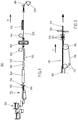
- FIG. 1 It shows the casting roll plant 100 according to the invention. It comprises, as seen in the casting direction R, a melt delivery system 105, a strip casting machine 110, a multi-roll smoothener 120, a shears 130, a temperature homogenizing furnace 140, optionally an induction heater 150, a roller table 155, a Steckel mill 160, a Cooling section 170 and, for example, a coiler 180.
- a melt delivery system 105 a melt delivery system 105
- strip casting machine 110 a strip casting machine 110
- a shears 130 e.g., a temperature homogenizing furnace 140
- optionally an induction heater 150 e.g., a roller table 155
- a Steckel mill 160 e.g., a Steckel mill 160
- Cooling section 170 e.g., a Cooling section 170
- the individual components of the casting rolling mill will be described in detail at least partially.
- the melt delivery system 105 consists essentially of a refractory lined or separately dumped position Heatable melt container, which the liquid metal, ie the melt, via a discharge nozzle using the force of gravity on the conveyor belt 118, see FIG. 2 guiding strip caster 110.
- a level measuring system in FIG. 1 not shown, ensures a constant melt level in the melt container and thus a constant flow of melt on the strip casting machine 110.
- the distribution of the melt over the casting width via flow guide elements (in FIG. 1 not shown) in the melt delivery system 105 or via arranged guide systems. These guide systems can conduct the melt with the aid of electromagnetic traveling fields or by the use of gas, which is passed through nozzles on the melt surface. The combination of several melt container with each other is possible.
- the flow guidance elements also extend beyond the melt delivery system into the region of the circulating conveyor belt 118 of the strip casting machine 110.
- the strip casting machine 110 consists, as in FIG. 2
- the transport belt 118 is preferably made of steel with a thickness of less than 3 mm. In the FIG. 2 shown smaller of the three rollers 115 ensures a uniform tension of the band.
- the lateral boundary of the strip casting plant is occupied by two horizontally encircling water - cooled dam block chains, in FIG. 2 Not shown.
- the conveyor belt is from below via spray nozzles, in FIG. 2 also not shown, cooled in the melt feed area with specific watering densities between 80 and 300 l / s / m 2 . Until the belt outlet the Wasserbeetzschungsêtn be returned to values between 10 and 100 liters / sec / m 2 .
- the belt cooling is operated with preferably> 100 m / bar negative pressure.
- the outside prevailing air pressure thus ensures the flat pressing of the metal strip on the support means between the two large rollers 115th
- the strip casting machine 110 according to the invention has a strip contact length of less than 7.5 m, the strip contact length being measured as the distance between the centers of the two large rolls 115.
- the casting speeds realized with the strip casting machine 110 are between 5 and 25 m / min, depending on the casting thickness.
- the strip casting machine 110 is the Multirollenglätt issued 120 downstream in the casting direction R.
- the multi-roll smoothing device 120 the cast strand is guided to improve its flatness with at least three pairs of rolls 124.
- the pairs of rollers are preferably driven individually. A reduction in the thickness of the casting strand generally does not take place in the multi-roll smoothing device.
- the example subsequent scissors 130 cuts the cast strand in slabs of predetermined length and decouples the previous casting process from a subsequent rolling process.
- the temperature homogenizing device 140 is arranged, which is typically designed as a tunnel furnace.
- the inductive heating downstream of the furnace which is provided only as an option, optionally provides for an increase in the temperature of the slabs and / or for a temperature compensation over the length of the slab before the slabs enter the downstream Steckel mill (160).
- the Steckel mill produces the desired final thickness with three, five, seven or more passes.
- the Steckel mill (160) is followed, as already mentioned above, in the casting direction by the cooling section 170 and the reel 180 for winding the pre-strips into a collar 250.
- the casting roll plant according to the invention thus formed has the advantage that the slabs, after passing through the temperature homogenizing device 140, can be fed directly into the Steckel rolling mill 160 without any loss of time or energy or without heat loss Perform a first pass without having to be wound up first.
- the induction heater 150 and / or the scissors 130 are arranged between the temperature homogenizer 140 and the Steckel mill 160.
Landscapes
- Engineering & Computer Science (AREA)
- Mechanical Engineering (AREA)
- Metal Rolling (AREA)
Description
Die Erfindung betrifft eine Gießwalzanlage mit einer Bandgießmaschine und ein Verfahren zum Herstellen von Vorband. Konkret betrifft die Erfindung kleine Gießwalzanlagen, sogenannte Micromillanlagen, zur Herstellung von Flachstahl mit einer Jahresproduktion zwischen 350.000 und 700.000 t Kohlenstoffstahl. Das erfindungsgemäße Anlagenkonzept zeichnet sich aus durch geringe Investitions- und Produktionskosten, eine schnelle Projektrealisierung mit kurzem Return on Invest und durch ein kompaktes Anlagenlayout. Die erfindungsgemäße Anlage eignet sich besonders für Stahlerzeuger in Regionen, wo bisher keine Flachstahlerzeugung stattfand und wo eine Spezialisierung auf regionale Anforderungen erfolgen soll.The invention relates to a casting and rolling plant with a strip casting machine and a method for producing pre-strip. Specifically, the invention relates to small caster rolling mills, so-called micromill plants, for the production of flat steel with an annual production between 350,000 and 700,000 t of carbon steel. The plant concept according to the invention is characterized by low investment and production costs, rapid project implementation with a short return on investment and a compact plant layout. The plant according to the invention is particularly suitable for steel producers in regions where so far no flat steel production took place and where a specialization to regional requirements should take place.
Gießwalzanlagen mit Bandgießmaschinen sind im Stand der Technik grundsätzlich bekannt. Einen auch heute noch gültigen umfassenden Überblick über die Grundlagen des Bandgießens gibt der Artikel von
Weiterer Stand der Technik zu Gießwalzanlagen mit Bandgießmaschinen findet sich z. B. in der
Gleichermaßen offenbart die
Ein alternatives Anlagenkonzept mit einer Bandgießmaschine ist aus der europäischen Patentschrift
Die deutsche Offenlegungsschrift
Die internationale Patentanmeldung
Die Oberbegriffe der Ansprüche 1 und 9 basieren auf der oben genannten
Ausgehend von diesem Stand der Technik liegt der Erfindung die Aufgabe zugrunde, eine Gießwalzanlage und ein Verfahren zum Herstellen von Brammen mit Hilfe einer Bandgießmaschine derart weiterzubilden, dass die Gießwalzanlage kompakter gebaut werden kann und dass bei dem Herstellungs-Verfahren Zeit und Energie eingespart werden können.Based on this prior art, the invention has the object, a cast rolling and a method for producing slabs using a strip casting machine such that the casting mill can be made more compact and that in the manufacturing process time and energy can be saved.
Die Aufgabe wird vorrichtungstechnisch durch die in Patentanspruch 1 beanspruchte Gießwalzanlage gelöst. Diese ist dadurch gekennzeichnet, dass die Gießmaschine als Bandgießmaschine mit einem umlaufenden gekühlten Transportband zum Gießen des Gießstrangs mit einer Gießdicke zwischen 10 und 20 mm ausgebildet ist; dass zwischen dem Ausgang der Bandgießmaschine und der Temperatur-Homogenisierungseinrichtung eine Multirollenglätteinrichtung angeordnet ist; und dass zwischen dem Ausgang der Temperatur-Homogenisierungseinrichtung und dem Steckelwalzwerk ein Rollgang vorgesehen ist zum Zuführen der Brammen direkt in das Steckelwalzwerk.The object is achieved by the device technology by the claimed in claim 1 casting rolling. This is characterized in that the casting machine is designed as a strip casting machine with a circulating cooled conveyor belt for casting the casting strand with a casting thickness between 10 and 20 mm; that between the output of the strip casting machine and the temperature homogenizing means a Multirollenglätteinrichtung is arranged; and that between the exit of the temperature homogenizer and the Steckel mill a roller table is provided for feeding the slabs directly into the Steckel mill.
Im Rahmen der vorliegenden Beschreibung wird das Wort "Gießstrang" für das Gießprodukt zwischen Kokille und Schere; das Wort "Bramme" für das Gießprodukt zwischen Schere und Steckelwalzwerk und das Wort "Vorband" für das Gießprodukt zwischen Steckelwalzwerk und Haspel verwendet. Brammen entstehen durch Zerteilen des Gießstrangs; Vorbänder entstehen durch Dickenreduktion der Brammen mit mindestens einem Stich.In the context of the present description, the word "Gießstrang" for the cast product between mold and scissors; the word "slab" is used for the cast product between scissors and Steckel mill and the word "Vorband" for the cast product between Steckel mill and reel. Slabs are produced by dividing the casting strand; Pre-bands are produced by reducing the thickness of the slabs with at least one stitch.
Das beanspruchte Anlagenkonzept bietet den Vorteil, dass hinter der Temperatur-Homogenisierungseinrichtung die Brammen direkt in das Steckelwalzwerk eingeführt und dort einem ersten Stich unterzogen werden können, ohne dass zuvor ein Aufwickeln der Brammen erforderlich wäre. Ein Vorgerüst ist nicht vorgesehen und nicht erforderlich. Durch das Einsparen des Vorgerüstes und einer Aufwickeleinrichtung zum Aufwickeln der Brammen aus der Temperatur-Homogenisierungseinrichtung kann die Anlage kompakter gebaut werden und Investitionskosten können eingespart werden. Außerdem ist dieses Anlagenkonzept sehr energieeffizient, weil zwischen der Temperatur-Homogenisierungseinrichtung und dem Steckelwalzwerk keine nennenswerten Temperatur-Verluste entstehen, etwa durch ein Zwischenlagern oder Umhängen von Coils, wie dies aus dem Stand der Technik bekannt ist.The claimed plant concept has the advantage that behind the temperature homogenizing device, the slabs can be introduced directly into the Steckel mill and subjected to a first pass there without previously requiring a winding of the slabs. A roughing stand is not provided and not required. By saving the Vorgerüstes and a take-up device for winding the slabs from the temperature-homogenizer, the system can be made more compact and investment costs can be saved. In addition, this system concept is very energy efficient because no significant temperature losses occur between the temperature homogenizer and the Steckel mill, such as by interim storage or wrapping of coils, as is known in the prior art.
Gemäß einem ersten Ausführungsbeispiel der Erfindung sind dem Steckwalzwerk stromaufwärts und stromabwärts, jeweils auf die Gießrichtung bezogen, Wickelöfen, sogenannte Steckel, zugeordnet. Beide Steckel weisen jeweils nur eine Wickeleinrichtung auf und sind jeweils auch nur ausgebildet zum Aufwickeln des Vorbandes nach einem Stich des Steckelwalzwerks und zum Abgeben des Vorbandes an das Steckelwalzwerk für den nachfolgenden Stich. Insbesondere der stromaufwärts angeordnete Wickelofen ist nicht dazu ausgebildet, die Brammen z.B. aus der Temperatur-Homogenisierungseinrichtung aufzunehmen. Er weist zu diesem Zweck keine zweite Wickeleinrichtung bzw. keine zweite Station auf, welche das Aufwickeln der Brammen aus der Temperatur-Homogenisierungseinrichtung ermöglichen würde und welche weiterhin das Umsetzen des so erzeugten Coils ermöglichen würde zum Zuführen der Brammen zu dem Steckelwalzwerk.According to a first embodiment of the invention, the Steckwalzwerk upstream and downstream, in each case based on the casting direction, winding furnaces, so-called Steckel assigned. Both Steckel each have only one winding device and are each only designed to wind the pre-strip after a pass of the Steckel mill and for dispensing the pre-strip to the Steckel mill for the following stitch. In particular, the upstream wind-up furnace is not designed to receive the slabs, e.g. from the temperature homogenizer. It has for this purpose no second winding device or no second station, which would allow the winding of the slabs from the temperature-homogenizing device and which would further allow the conversion of the coil thus produced for feeding the slabs to the Steckel mill.
Die Schere zum Zerteilen des von der Gießmaschine gegossenen Gießstrangs in Brammen vorbestimmter Länge kann zwischen der Multirollenglätteinrichtung und dem Eingang der Temperatur-Homogenisierungseinrichtung oder zwischen dem Ausgang der Temperatur-Homogenisierungseinrichtung und dem Steckelwalzwerk angeordnet sein.The shears for dividing the cast strand cast by the casting machine into slabs of predetermined length may be disposed between the multi-roll smoother and the entrance of the temperature homogenizer or between the exit of the temperature homogenizer and the Steckel mill.
Zwischen dem Ausgang der Temperatur-Homogenisierungseinrichtung und dem Steckelwalzwerk ist vorzugsweise eine Induktionsheizeinrichtung angeordnet zum Aufheizen der Brammen auf eine für das Steckelwalzen geeignete Temperatur.Between the output of the temperature homogenizer and the Steckel mill, an induction heating device is preferably arranged for heating the slabs to a temperature suitable for the Steckel rollers.
Die oben genannte Aufgabe der Erfindung wird weiterhin durch das in Patentanspruch 9 beanspruchte Verfahren gelöst. Die Vorteile dieser verfahrenstechnischen Lösung entsprechen den oben in Bezug auf die beanspruchte Gießwalzanlage genannten Vorteilen.The above object of the invention is further achieved by the method claimed in claim 9. The advantages of this process solution correspond to the advantages mentioned above with respect to the claimed cast roll mill.
Das Verfahren sieht vor, dass der Gießstrang mit einer Gießbandgeschwindigkeit von 5 bis 25 m/min. gegossen wird. Das erfindungsgemäße Verfahren und die zugehörige erfindungsgemäße Gießwalzanlage sind insbesondere vorgesehen zum Erzeugen von Vorbändern aus Kohlenstoffstahl.The method provides that the casting strand with a casting belt speed of 5 to 25 m / min. is poured. The method according to the invention and the associated cast roll plant according to the invention are in particular provided for producing carbon steel pre-strips.
Weitere vorteilhafte Ausgestaltungen der beanspruchten Gießwalzanlage und des beanspruchten Verfahrens sind Gegenstand der abhängigen Ansprüche.Further advantageous embodiments of the claimed casting and the claimed method are the subject of the dependent claims.
Der Erfindung sind insgesamt 2 Figuren beigefügt, wobei
-
Figur 1 die erfindungsgemäße Gießwalzanlage; und -
Figur 2 die erfindungsgemäße Bandgießmaschine im Detail
-
FIG. 1 the cast roll mill according to the invention; and -
FIG. 2 the strip casting machine according to the invention in detail
Die Erfindung wird nachfolgend unter Bezugnahme auf die genannten Figuren in Form von Ausführungsbeispielen detailliert beschrieben. In beiden Figuren sind gleiche technische Elemente mit gleichen Bezugszeichen bezeichnet.The invention will be described in detail below with reference to the said figures in the form of embodiments. In both figures, the same technical elements are designated by the same reference numerals.
Das Schmelzenaufgabesystem 105 besteht im Wesentlichen aus einem mit Feuerfestmaterial ausgemauerten separat bzw. in weggekippter Position aufheizbaren Schmelzenbehälter, welcher das Flüssigmetall, d. h. die Schmelze, über eine Auslaufdüse unter Nutzung der Schwerkraft auf das Transportband 118, siehe
Die Bandgießmaschine 110 besteht, wie in
Der Bandgießmaschine 110 ist die Multirollenglätteinrichtung 120 in Gießrichtung R nachgeordnet. In der Multirollenglätteinrichtung 120 wird der Gießstrang zur Verbesserung seiner Planheit mit mindestens drei Rollenpaaren 124 geführt. Die Rollenpaare sind bevorzugt einzeln angetrieben. Eine Dickenreduktion des Gießstranges findet in der Multirollenglätteinrichtung grundsätzlich nicht statt.The
Die beispielsweise anschließende Schere 130 schneidet den Gießstrang in Brammen vorgegebener Länge und entkoppelt den bisher erfolgten Gießprozess von einem nachfolgenden Walzprozess.The example
In Gießrichtung R hinter der Multirollenglätteinrichtung 120, vorzugsweise auch hinter der Schere 120, ist die Temperatur-Homogenisierungseinrichtung 140 angeordnet, welche typischerweise als Tunnelofen ausgebildet ist. Die dem Ofen nachgeschaltete induktive Heizung, welche lediglich optional vorgesehen ist, sorgt gegebenenfalls für eine Erhöhung der Temperatur der Brammen und/oder für einen Temperaturausgleich über der Brammenlänge vor Einlauf der Brammen in das nachfolgende Steckelwalzwerk (160). Das Steckelwalzwerk erzeugt mit drei, fünf, sieben oder mehr Stichen die gewünschte Enddicke. Dem Steckelwalzwerk (160) folgen, wie oben bereits erwähnt, in Gießrichtung die Kühlstrecke 170 und der Haspel 180 zum Aufwickeln der Vorbänder zu einem Bund 250.In the casting direction R behind the
Verfahrenstechnisch bietet die so ausgebildete erfindungsgemäße Gießwalzanlage den Vorteil, dass die Brammen nach Durchlaufen der Temperatur-Homogenisierungseinrichtung 140 im Wesentlichen ohne Zeit- und Energieverlust, bzw. ohne Wärmeverlust, direkt in das Steckelwalzwerk 160 zur Durchführung eines ersten Stichs einlaufen können, ohne zuvor aufgewickelt werden zu müssen. Allenfalls ist zwischen der Temperatur-Homogenisierungseinrichtung 140 und dem Steckelwalzwerk 160 noch die Induktionsheizung 150 und/oder die Schere 130 angeordnet.From a process engineering point of view, the casting roll plant according to the invention thus formed has the advantage that the slabs, after passing through the
- 100100
- Gießwalzanlagecontinuous casting and rolling
- 105105
- SchmelzenaufgabensystemMelt application system
- 110110
- Bandgießmaschinestrip caster
- 115115
- große Rollenbig roles
- 118118
- beschichtetes Transportbandcoated conveyor belt
- 120120
- MultirollenglätteinrichtungMultirollenglätteinrichtung
- 124124
- drei Rollenpaarethree pairs of roles
- 130130
- Scherescissors
- 140140
- Temperatur-HomogenisierungseinrichtungTemperature-homogenizing
- 150150
- Induktionsheizeinrichtunginduction heating
- 155155
- Rollgangroller table
- 160160
- SteckelwalzwerkSteckel mill
- 162162
- Wickelofencoiler furnace
- 164164
- Wickelofencoiler furnace
- 170170
- Kühlstreckecooling section
- 180180
- Haspeleinrichtungcoiler
- 200200
- Gießstrangcast strand
- 210210
- Brammeslab
- 220220
- Vorbandopening act
- 250250
- BundFederation
- RR
- Gießrichtungcasting
Claims (15)
- Casting and rolling plant (100) comprising
a casting machine for casting a cast strip (200);
shears (130) for dividing up the cast strip into slabs (21) of predetermined length;
a temperature homogenisation device (140); and
a Steckel rolling mill (160) for rolling the slabs to form pre-strips (220) of predetermined thickness;
characterised in that
the casting machine is constructed as a strip casting machine (110) with a circulating cooled transport belt (118) for casting the cast strip (200) with a cast thickness between 10 and 20 millimetres;
a multi-roller smoothing device (120) is arranged between the outlet of the strip casting machine (110) and the temperature homogenisation device (140); and
a roller path for feeding the slabs directly to the Steckel rolling mill (160) is provided between the outlet of the temperature homogenisation device and the Steckel rolling mill. - Casting and rolling plant (100) according to claim 1, characterised in that the winding furnaces (162, 164) associated with the Steckel rolling mill (160) upstream and downstream thereof each have only one winding device and are each constructed only for winding up the pre-strip from the Steckel rolling mill (160) and delivering the pre-strip to the Steckel rolling mill.
- Casting and rolling plant (100) according to one of the preceding claims, characterised in that an induction heating device (150) is arranged between the outlet of the temperature homogenisation device (140) and the Steckel rolling mill (160).
- Casting and rolling plant (100) according to any one of the preceding claims, characterised in that the multi-roller smoothing device (120) comprises at least three roller pairs (124), of which at least one roller pair is driven.
- Casting and rolling plant (100) according to any one of the preceding claims, characterised by a cooling path (170) downstream of the Steckel rolling mill.
- Casting and rolling plant (100) according to claim 5, characterised by a coiler (180) downstream of the cooling path (170).
- Casting and rolling plant (100) according to any one of the preceding claims, characterised in that the strip casting machine (110) has a strip contact length of less than 7.5 metres.
- Casting and rolling plant (100) according to any one of the preceding claims, characterised in that the shears (130) for dividing up the cast strip into slabs of predetermined length are arranged between the multi-roller smoothing device (120) and the inlet of the temperature homogenisation device (140) or between the outlet of the temperature homogenisation device (140) and the Steckel rolling mill (160).
- Method of producing slabs, comprising the following steps:producing a cast strip (200);homogenising the temperature of the cast strip (200);dividing up the cast strip into slabs before or after the homogenisation;after temperature homogenisation: introducing the slabs directly into a Steckel rolling mill (160), so as to there be subjected to a first pass, before they are fed for the first time to a winding furnace of the Steckel rolling mill; andthickness reduction of the slabs in the Steckel rolling mill with at least three passes to a desired thickness to form a pre-strip (220);characterised in thatthe production of the cast strip (200) is carried out by strip casting, wherein the cast strip (200) is cast with a thickness between 10 and 20 millimetres; andthe cast strip (200) is smoothed before its temperature is homogenised.
- Method according to claim 9, characterised in that the casting speed of the cast strip is between 5 and 25 metres per minute.
- Method according to claim 9 or 10, characterised in that the slabs are heated again, preferably inductively, after the temperature homogenisation, but before entry thereof into the Steckel rolling mill (160).
- Method according to any one of claims 9 to 11, characterised in that the cast strip prior to entry thereof into the Steckel rolling mill is divided up into slabs of predetermined length.
- Method according to any one of claims 9 to 12, characterised in that the cast strip (200) consists of carbon steel.
- Method according to any one of claims 9 to 13, characterised in that the pre-strips are cooled after exit thereof from the Steckel rolling mill.
- Method according to claim 14, characterised in that the pre-strips are wound up to form a coil (250) after they have been cooled.
Applications Claiming Priority (2)
| Application Number | Priority Date | Filing Date | Title |
|---|---|---|---|
| DE201310214940 DE102013214940A1 (en) | 2013-07-30 | 2013-07-30 | Cast rolling mill and method for producing slabs |
| PCT/EP2014/066318 WO2015014864A1 (en) | 2013-07-30 | 2014-07-29 | Casting and rolling plant and method for producing slabs |
Publications (2)
| Publication Number | Publication Date |
|---|---|
| EP3027331A1 EP3027331A1 (en) | 2016-06-08 |
| EP3027331B1 true EP3027331B1 (en) | 2017-03-01 |
Family
ID=51266307
Family Applications (1)
| Application Number | Title | Priority Date | Filing Date |
|---|---|---|---|
| EP14747587.5A Active EP3027331B1 (en) | 2013-07-30 | 2014-07-29 | Casting and rolling plant and method for producing slabs |
Country Status (4)
| Country | Link |
|---|---|
| EP (1) | EP3027331B1 (en) |
| CN (1) | CN105473247A (en) |
| DE (1) | DE102013214940A1 (en) |
| WO (1) | WO2015014864A1 (en) |
Families Citing this family (4)
| Publication number | Priority date | Publication date | Assignee | Title |
|---|---|---|---|---|
| DE102017221969A1 (en) | 2017-12-05 | 2019-06-06 | Sms Group Gmbh | Method and device for producing a band-shaped composite material |
| ES2953325T3 (en) | 2020-09-24 | 2023-11-10 | Primetals Technologies Austria GmbH | Casting Composite Rolling Facility and Procedure for Operating Casting Composite Rolling Facility |
| DE102021211339A1 (en) * | 2020-10-13 | 2022-04-14 | Sms Group Gmbh | Device and method for the production of hot-rolled metal strips |
| CN120619306B (en) * | 2025-04-28 | 2026-03-31 | 有研金属复合材料(北京)股份公司 | An electromagnetically assisted horizontal continuous casting device and method for aluminum alloy ingots |
Family Cites Families (9)
| Publication number | Priority date | Publication date | Assignee | Title |
|---|---|---|---|---|
| DE4009860C2 (en) * | 1990-03-28 | 1999-11-18 | Schloemann Siemag Ag | Process and plant for the production of hot-rolled steel strip, in particular for stainless steels, from strip-shaped continuous material |
| DE19758108C1 (en) | 1997-12-17 | 1999-01-14 | Mannesmann Ag | Method and installation for continuous production of hot rolled thin flat products |
| DE102004057427A1 (en) * | 2004-11-27 | 2006-06-01 | Sms Demag Ag | Apparatus and method for continuous casting |
| DE102004062636B4 (en) * | 2004-12-21 | 2007-05-24 | Salzgitter Flachstahl Gmbh | Device for horizontal strip casting of steel |
| DE102005052774A1 (en) | 2004-12-21 | 2006-06-29 | Salzgitter Flachstahl Gmbh | Method of producing hot strips of lightweight steel |
| DE102007057278A1 (en) * | 2007-08-04 | 2009-02-05 | Sms Demag Ag | Method and apparatus for equalizing the heat transfer of a cast product during its reimbursement on the metal conveyor belt of a horizontal strip caster |
| KR101332196B1 (en) * | 2008-12-09 | 2013-11-25 | 에스엠에스 지마크 악티엔게젤샤프트 | Method for producing strips of metal, and production line for performing the method |
| DE102010050647A1 (en) | 2009-11-21 | 2011-05-26 | Sms Siemag Aktiengesellschaft | Plant and method for casting and rolling metal |
| IT1405453B1 (en) * | 2010-06-14 | 2014-01-10 | Danieli Off Mecc | LAMINATION PROCEDURE FOR PLAN PRODUCTS AND ITS LAMINATION LINE |
-
2013
- 2013-07-30 DE DE201310214940 patent/DE102013214940A1/en not_active Withdrawn
-
2014
- 2014-07-29 CN CN201480043513.9A patent/CN105473247A/en active Pending
- 2014-07-29 EP EP14747587.5A patent/EP3027331B1/en active Active
- 2014-07-29 WO PCT/EP2014/066318 patent/WO2015014864A1/en not_active Ceased
Non-Patent Citations (1)
| Title |
|---|
| None * |
Also Published As
| Publication number | Publication date |
|---|---|
| WO2015014864A1 (en) | 2015-02-05 |
| EP3027331A1 (en) | 2016-06-08 |
| DE102013214940A1 (en) | 2015-02-05 |
| CN105473247A (en) | 2016-04-06 |
Similar Documents
| Publication | Publication Date | Title |
|---|---|---|
| EP0415987B2 (en) | Process for continuous production of steel strip or steel sheet from flat products made by the circular-arc type continuous casting process | |
| EP1960131B1 (en) | Method and device for producing a metal strip by continuous casting and rolling | |
| EP2964404B1 (en) | Method for producing a metal strip by casting and rolling | |
| DE69102280T2 (en) | METHOD AND SYSTEM FOR THE PRODUCTION OF STEEL TAPE COILS DIRECTLY GENERATED FROM A HOT ROLLING MILL WITH COLD ROLLING PROPERTIES. | |
| EP3535076B1 (en) | Combined casting-rolling installation and method for the continuous production of a hot-rolled finished strip | |
| EP2710159B1 (en) | Method and device for preparing steel milled goods before hot rolling | |
| EP3504013B2 (en) | Method for producing a metal strip in a cast-rolling installation | |
| DE202011110779U1 (en) | Plant for the production of flat rolled products | |
| EP3558563B1 (en) | Method for the endless manufacture of a coiled hot rolled sheet in a combined casting and rolling installation, and a combined casting and rolling installation | |
| DE102008003222A1 (en) | Compact flexible CSP system for continuous, semi-continuous and batch operation | |
| EP3797006B1 (en) | Casting-rolling system for batch and continuous operation | |
| EP4297918B1 (en) | Composite casting and rolling system and method for producing hot strip having a final thickness of less than 1.2 mm on the composite casting and rolling system | |
| AT504782A4 (en) | METHOD FOR PRODUCING A HOT-ROLLED STEEL STRIP AND COMBINED CASTING AND ROLLING MACHINE TO PERFORM THE METHOD | |
| DE10304318C5 (en) | Process for rolling thin and / or thick slabs of steel materials to hot strip | |
| EP1113888B1 (en) | Method and device for producing a hot-rolled steel strip from molten steel | |
| EP3027331B1 (en) | Casting and rolling plant and method for producing slabs | |
| EP3016762B1 (en) | Cast-rolling installation and method for producing metallic rolled stock | |
| WO2016165933A1 (en) | Casting/rolling system and method for operating same | |
| EP3027330B1 (en) | Continuous casting and rolling installation for producing metal strips | |
| EP2663412B1 (en) | Equipment and method for producing hot-rolled strips |
Legal Events
| Date | Code | Title | Description |
|---|---|---|---|
| PUAI | Public reference made under article 153(3) epc to a published international application that has entered the european phase |
Free format text: ORIGINAL CODE: 0009012 |
|
| 17P | Request for examination filed |
Effective date: 20160229 |
|
| AK | Designated contracting states |
Kind code of ref document: A1 Designated state(s): AL AT BE BG CH CY CZ DE DK EE ES FI FR GB GR HR HU IE IS IT LI LT LU LV MC MK MT NL NO PL PT RO RS SE SI SK SM TR |
|
| AX | Request for extension of the european patent |
Extension state: BA ME |
|
| GRAP | Despatch of communication of intention to grant a patent |
Free format text: ORIGINAL CODE: EPIDOSNIGR1 |
|
| DAX | Request for extension of the european patent (deleted) | ||
| INTG | Intention to grant announced |
Effective date: 20161010 |
|
| GRAS | Grant fee paid |
Free format text: ORIGINAL CODE: EPIDOSNIGR3 |
|
| GRAA | (expected) grant |
Free format text: ORIGINAL CODE: 0009210 |
|
| AK | Designated contracting states |
Kind code of ref document: B1 Designated state(s): AL AT BE BG CH CY CZ DE DK EE ES FI FR GB GR HR HU IE IS IT LI LT LU LV MC MK MT NL NO PL PT RO RS SE SI SK SM TR |
|
| REG | Reference to a national code |
Ref country code: GB Ref legal event code: FG4D Free format text: NOT ENGLISH |
|
| REG | Reference to a national code |
Ref country code: CH Ref legal event code: EP Ref country code: AT Ref legal event code: REF Ref document number: 870667 Country of ref document: AT Kind code of ref document: T Effective date: 20170315 |
|
| REG | Reference to a national code |
Ref country code: IE Ref legal event code: FG4D Free format text: LANGUAGE OF EP DOCUMENT: GERMAN |
|
| REG | Reference to a national code |
Ref country code: DE Ref legal event code: R096 Ref document number: 502014002876 Country of ref document: DE |
|
| REG | Reference to a national code |
Ref country code: NL Ref legal event code: MP Effective date: 20170301 |
|
| REG | Reference to a national code |
Ref country code: LT Ref legal event code: MG4D |
|
| PG25 | Lapsed in a contracting state [announced via postgrant information from national office to epo] |
Ref country code: NO Free format text: LAPSE BECAUSE OF FAILURE TO SUBMIT A TRANSLATION OF THE DESCRIPTION OR TO PAY THE FEE WITHIN THE PRESCRIBED TIME-LIMIT Effective date: 20170601 Ref country code: LT Free format text: LAPSE BECAUSE OF FAILURE TO SUBMIT A TRANSLATION OF THE DESCRIPTION OR TO PAY THE FEE WITHIN THE PRESCRIBED TIME-LIMIT Effective date: 20170301 Ref country code: HR Free format text: LAPSE BECAUSE OF FAILURE TO SUBMIT A TRANSLATION OF THE DESCRIPTION OR TO PAY THE FEE WITHIN THE PRESCRIBED TIME-LIMIT Effective date: 20170301 Ref country code: GR Free format text: LAPSE BECAUSE OF FAILURE TO SUBMIT A TRANSLATION OF THE DESCRIPTION OR TO PAY THE FEE WITHIN THE PRESCRIBED TIME-LIMIT Effective date: 20170602 Ref country code: FI Free format text: LAPSE BECAUSE OF FAILURE TO SUBMIT A TRANSLATION OF THE DESCRIPTION OR TO PAY THE FEE WITHIN THE PRESCRIBED TIME-LIMIT Effective date: 20170301 |
|
| PG25 | Lapsed in a contracting state [announced via postgrant information from national office to epo] |
Ref country code: BG Free format text: LAPSE BECAUSE OF FAILURE TO SUBMIT A TRANSLATION OF THE DESCRIPTION OR TO PAY THE FEE WITHIN THE PRESCRIBED TIME-LIMIT Effective date: 20170601 Ref country code: RS Free format text: LAPSE BECAUSE OF FAILURE TO SUBMIT A TRANSLATION OF THE DESCRIPTION OR TO PAY THE FEE WITHIN THE PRESCRIBED TIME-LIMIT Effective date: 20170301 Ref country code: LV Free format text: LAPSE BECAUSE OF FAILURE TO SUBMIT A TRANSLATION OF THE DESCRIPTION OR TO PAY THE FEE WITHIN THE PRESCRIBED TIME-LIMIT Effective date: 20170301 Ref country code: ES Free format text: LAPSE BECAUSE OF FAILURE TO SUBMIT A TRANSLATION OF THE DESCRIPTION OR TO PAY THE FEE WITHIN THE PRESCRIBED TIME-LIMIT Effective date: 20170301 Ref country code: SE Free format text: LAPSE BECAUSE OF FAILURE TO SUBMIT A TRANSLATION OF THE DESCRIPTION OR TO PAY THE FEE WITHIN THE PRESCRIBED TIME-LIMIT Effective date: 20170301 |
|
| PG25 | Lapsed in a contracting state [announced via postgrant information from national office to epo] |
Ref country code: NL Free format text: LAPSE BECAUSE OF FAILURE TO SUBMIT A TRANSLATION OF THE DESCRIPTION OR TO PAY THE FEE WITHIN THE PRESCRIBED TIME-LIMIT Effective date: 20170301 |
|
| PG25 | Lapsed in a contracting state [announced via postgrant information from national office to epo] |
Ref country code: RO Free format text: LAPSE BECAUSE OF FAILURE TO SUBMIT A TRANSLATION OF THE DESCRIPTION OR TO PAY THE FEE WITHIN THE PRESCRIBED TIME-LIMIT Effective date: 20170301 Ref country code: EE Free format text: LAPSE BECAUSE OF FAILURE TO SUBMIT A TRANSLATION OF THE DESCRIPTION OR TO PAY THE FEE WITHIN THE PRESCRIBED TIME-LIMIT Effective date: 20170301 Ref country code: CZ Free format text: LAPSE BECAUSE OF FAILURE TO SUBMIT A TRANSLATION OF THE DESCRIPTION OR TO PAY THE FEE WITHIN THE PRESCRIBED TIME-LIMIT Effective date: 20170301 Ref country code: SK Free format text: LAPSE BECAUSE OF FAILURE TO SUBMIT A TRANSLATION OF THE DESCRIPTION OR TO PAY THE FEE WITHIN THE PRESCRIBED TIME-LIMIT Effective date: 20170301 |
|
| PG25 | Lapsed in a contracting state [announced via postgrant information from national office to epo] |
Ref country code: IS Free format text: LAPSE BECAUSE OF FAILURE TO SUBMIT A TRANSLATION OF THE DESCRIPTION OR TO PAY THE FEE WITHIN THE PRESCRIBED TIME-LIMIT Effective date: 20170701 Ref country code: PL Free format text: LAPSE BECAUSE OF FAILURE TO SUBMIT A TRANSLATION OF THE DESCRIPTION OR TO PAY THE FEE WITHIN THE PRESCRIBED TIME-LIMIT Effective date: 20170301 Ref country code: SM Free format text: LAPSE BECAUSE OF FAILURE TO SUBMIT A TRANSLATION OF THE DESCRIPTION OR TO PAY THE FEE WITHIN THE PRESCRIBED TIME-LIMIT Effective date: 20170301 Ref country code: PT Free format text: LAPSE BECAUSE OF FAILURE TO SUBMIT A TRANSLATION OF THE DESCRIPTION OR TO PAY THE FEE WITHIN THE PRESCRIBED TIME-LIMIT Effective date: 20170703 |
|
| REG | Reference to a national code |
Ref country code: DE Ref legal event code: R097 Ref document number: 502014002876 Country of ref document: DE |
|
| PLBE | No opposition filed within time limit |
Free format text: ORIGINAL CODE: 0009261 |
|
| STAA | Information on the status of an ep patent application or granted ep patent |
Free format text: STATUS: NO OPPOSITION FILED WITHIN TIME LIMIT |
|
| PG25 | Lapsed in a contracting state [announced via postgrant information from national office to epo] |
Ref country code: DK Free format text: LAPSE BECAUSE OF FAILURE TO SUBMIT A TRANSLATION OF THE DESCRIPTION OR TO PAY THE FEE WITHIN THE PRESCRIBED TIME-LIMIT Effective date: 20170301 |
|
| 26N | No opposition filed |
Effective date: 20171204 |
|
| PG25 | Lapsed in a contracting state [announced via postgrant information from national office to epo] |
Ref country code: SI Free format text: LAPSE BECAUSE OF FAILURE TO SUBMIT A TRANSLATION OF THE DESCRIPTION OR TO PAY THE FEE WITHIN THE PRESCRIBED TIME-LIMIT Effective date: 20170301 |
|
| REG | Reference to a national code |
Ref country code: CH Ref legal event code: PL |
|
| REG | Reference to a national code |
Ref country code: FR Ref legal event code: ST Effective date: 20180330 |
|
| PG25 | Lapsed in a contracting state [announced via postgrant information from national office to epo] |
Ref country code: LI Free format text: LAPSE BECAUSE OF NON-PAYMENT OF DUE FEES Effective date: 20170731 Ref country code: CH Free format text: LAPSE BECAUSE OF NON-PAYMENT OF DUE FEES Effective date: 20170731 |
|
| REG | Reference to a national code |
Ref country code: IE Ref legal event code: MM4A |
|
| PG25 | Lapsed in a contracting state [announced via postgrant information from national office to epo] |
Ref country code: FR Free format text: LAPSE BECAUSE OF NON-PAYMENT OF DUE FEES Effective date: 20170731 |
|
| REG | Reference to a national code |
Ref country code: BE Ref legal event code: MM Effective date: 20170731 |
|
| PG25 | Lapsed in a contracting state [announced via postgrant information from national office to epo] |
Ref country code: LU Free format text: LAPSE BECAUSE OF NON-PAYMENT OF DUE FEES Effective date: 20170729 |
|
| PG25 | Lapsed in a contracting state [announced via postgrant information from national office to epo] |
Ref country code: IE Free format text: LAPSE BECAUSE OF NON-PAYMENT OF DUE FEES Effective date: 20170729 |
|
| PG25 | Lapsed in a contracting state [announced via postgrant information from national office to epo] |
Ref country code: BE Free format text: LAPSE BECAUSE OF NON-PAYMENT OF DUE FEES Effective date: 20170731 |
|
| PG25 | Lapsed in a contracting state [announced via postgrant information from national office to epo] |
Ref country code: MT Free format text: LAPSE BECAUSE OF FAILURE TO SUBMIT A TRANSLATION OF THE DESCRIPTION OR TO PAY THE FEE WITHIN THE PRESCRIBED TIME-LIMIT Effective date: 20170301 |
|
| PG25 | Lapsed in a contracting state [announced via postgrant information from national office to epo] |
Ref country code: MC Free format text: LAPSE BECAUSE OF FAILURE TO SUBMIT A TRANSLATION OF THE DESCRIPTION OR TO PAY THE FEE WITHIN THE PRESCRIBED TIME-LIMIT Effective date: 20170301 Ref country code: HU Free format text: LAPSE BECAUSE OF FAILURE TO SUBMIT A TRANSLATION OF THE DESCRIPTION OR TO PAY THE FEE WITHIN THE PRESCRIBED TIME-LIMIT; INVALID AB INITIO Effective date: 20140729 |
|
| PG25 | Lapsed in a contracting state [announced via postgrant information from national office to epo] |
Ref country code: CY Free format text: LAPSE BECAUSE OF FAILURE TO SUBMIT A TRANSLATION OF THE DESCRIPTION OR TO PAY THE FEE WITHIN THE PRESCRIBED TIME-LIMIT Effective date: 20170301 |
|
| PG25 | Lapsed in a contracting state [announced via postgrant information from national office to epo] |
Ref country code: MK Free format text: LAPSE BECAUSE OF FAILURE TO SUBMIT A TRANSLATION OF THE DESCRIPTION OR TO PAY THE FEE WITHIN THE PRESCRIBED TIME-LIMIT Effective date: 20170301 |
|
| PG25 | Lapsed in a contracting state [announced via postgrant information from national office to epo] |
Ref country code: TR Free format text: LAPSE BECAUSE OF FAILURE TO SUBMIT A TRANSLATION OF THE DESCRIPTION OR TO PAY THE FEE WITHIN THE PRESCRIBED TIME-LIMIT Effective date: 20170301 |
|
| PG25 | Lapsed in a contracting state [announced via postgrant information from national office to epo] |
Ref country code: AL Free format text: LAPSE BECAUSE OF FAILURE TO SUBMIT A TRANSLATION OF THE DESCRIPTION OR TO PAY THE FEE WITHIN THE PRESCRIBED TIME-LIMIT Effective date: 20170301 |
|
| P01 | Opt-out of the competence of the unified patent court (upc) registered |
Effective date: 20230707 |
|
| PGFP | Annual fee paid to national office [announced via postgrant information from national office to epo] |
Ref country code: DE Payment date: 20250722 Year of fee payment: 12 |
|
| PGFP | Annual fee paid to national office [announced via postgrant information from national office to epo] |
Ref country code: IT Payment date: 20250724 Year of fee payment: 12 |
|
| PGFP | Annual fee paid to national office [announced via postgrant information from national office to epo] |
Ref country code: GB Payment date: 20250722 Year of fee payment: 12 |
|
| PGFP | Annual fee paid to national office [announced via postgrant information from national office to epo] |
Ref country code: AT Payment date: 20250722 Year of fee payment: 12 |