EP2983773B1 - Metered dose inhaler applicator - Google Patents
Metered dose inhaler applicator Download PDFInfo
- Publication number
- EP2983773B1 EP2983773B1 EP14764025.4A EP14764025A EP2983773B1 EP 2983773 B1 EP2983773 B1 EP 2983773B1 EP 14764025 A EP14764025 A EP 14764025A EP 2983773 B1 EP2983773 B1 EP 2983773B1
- Authority
- EP
- European Patent Office
- Prior art keywords
- mdi
- carrier
- housing
- applicator
- adjuster
- Prior art date
- Legal status (The legal status is an assumption and is not a legal conclusion. Google has not performed a legal analysis and makes no representation as to the accuracy of the status listed.)
- Active
Links
Images




Classifications
-
- A—HUMAN NECESSITIES
- A61—MEDICAL OR VETERINARY SCIENCE; HYGIENE
- A61M—DEVICES FOR INTRODUCING MEDIA INTO, OR ONTO, THE BODY; DEVICES FOR TRANSDUCING BODY MEDIA OR FOR TAKING MEDIA FROM THE BODY; DEVICES FOR PRODUCING OR ENDING SLEEP OR STUPOR
- A61M15/00—Inhalators
- A61M15/0001—Details of inhalators; Constructional features thereof
-
- A—HUMAN NECESSITIES
- A61—MEDICAL OR VETERINARY SCIENCE; HYGIENE
- A61M—DEVICES FOR INTRODUCING MEDIA INTO, OR ONTO, THE BODY; DEVICES FOR TRANSDUCING BODY MEDIA OR FOR TAKING MEDIA FROM THE BODY; DEVICES FOR PRODUCING OR ENDING SLEEP OR STUPOR
- A61M11/00—Sprayers or atomisers specially adapted for therapeutic purposes
- A61M11/04—Sprayers or atomisers specially adapted for therapeutic purposes operated by the vapour pressure of the liquid to be sprayed or atomised
-
- A—HUMAN NECESSITIES
- A61—MEDICAL OR VETERINARY SCIENCE; HYGIENE
- A61M—DEVICES FOR INTRODUCING MEDIA INTO, OR ONTO, THE BODY; DEVICES FOR TRANSDUCING BODY MEDIA OR FOR TAKING MEDIA FROM THE BODY; DEVICES FOR PRODUCING OR ENDING SLEEP OR STUPOR
- A61M11/00—Sprayers or atomisers specially adapted for therapeutic purposes
- A61M11/06—Sprayers or atomisers specially adapted for therapeutic purposes of the injector type
- A61M11/08—Pocket atomisers of the injector type
-
- A—HUMAN NECESSITIES
- A61—MEDICAL OR VETERINARY SCIENCE; HYGIENE
- A61M—DEVICES FOR INTRODUCING MEDIA INTO, OR ONTO, THE BODY; DEVICES FOR TRANSDUCING BODY MEDIA OR FOR TAKING MEDIA FROM THE BODY; DEVICES FOR PRODUCING OR ENDING SLEEP OR STUPOR
- A61M15/00—Inhalators
- A61M15/0065—Inhalators with dosage or measuring devices
-
- A—HUMAN NECESSITIES
- A61—MEDICAL OR VETERINARY SCIENCE; HYGIENE
- A61M—DEVICES FOR INTRODUCING MEDIA INTO, OR ONTO, THE BODY; DEVICES FOR TRANSDUCING BODY MEDIA OR FOR TAKING MEDIA FROM THE BODY; DEVICES FOR PRODUCING OR ENDING SLEEP OR STUPOR
- A61M15/00—Inhalators
- A61M15/009—Inhalators using medicine packages with incorporated spraying means, e.g. aerosol cans
-
- A—HUMAN NECESSITIES
- A61—MEDICAL OR VETERINARY SCIENCE; HYGIENE
- A61M—DEVICES FOR INTRODUCING MEDIA INTO, OR ONTO, THE BODY; DEVICES FOR TRANSDUCING BODY MEDIA OR FOR TAKING MEDIA FROM THE BODY; DEVICES FOR PRODUCING OR ENDING SLEEP OR STUPOR
- A61M2205/00—General characteristics of the apparatus
- A61M2205/27—General characteristics of the apparatus preventing use
- A61M2205/276—General characteristics of the apparatus preventing use preventing unwanted use
-
- A—HUMAN NECESSITIES
- A61—MEDICAL OR VETERINARY SCIENCE; HYGIENE
- A61M—DEVICES FOR INTRODUCING MEDIA INTO, OR ONTO, THE BODY; DEVICES FOR TRANSDUCING BODY MEDIA OR FOR TAKING MEDIA FROM THE BODY; DEVICES FOR PRODUCING OR ENDING SLEEP OR STUPOR
- A61M2205/00—General characteristics of the apparatus
- A61M2205/58—Means for facilitating use, e.g. by people with impaired vision
- A61M2205/586—Ergonomic details therefor, e.g. specific ergonomics for left or right-handed users
Definitions
- MDI Metered dose inhalers
- a MDI typically includes a canister, a metering valve, and an actuator.
- the canister holds a pressurized medicine
- the metering valve restricts an amount of medicine that is dispensed when the MDI is actuated
- the actuator that typically includes a stem and nozzle in communication with the metering valve, provide the ability to dispense a limited amount of medicine from the canister and metering valve in an aerosolized from.
- Patients may have difficulty actuating a MDI or storing a MDI in a manner that prevents inadvertent actuations. Accordingly, improved applicators for use with a MDI that provide the ability to easily actuate the MDI and that provide for convenient storage of the MDI are desirable.
- the present invention provides a metered dose inhaler applicator as defined in claim 1. Further embodiments of the invention are defined in the dependent claims.
- Fig. 1 is a cross-sectional view of one implementation of a MDI 112 positioned in a MDI applicator 102.
- the MDI applicator 102 may include a lever 104, a housing 106, a carrier 108, and an adjuster 110.
- the lever 104 is positioned on the MDI applicator 102 such that when a force is applied to the lever 104 of the MDI applicator 102, the lever 104 transfers the force to a canister 114 of the MDI 112 positioned in the MDI applicator 102.
- the MDI 112 dispenses an aerosolized medicine that a patient may inhale.
- Figs. 3-6 and 51A-52 illustrate various views of the MDI applicator 102, 202;
- Fig 4 illustrates an exploded view of the MDI applicator 102, 202;
- Figs. 8-11 and 53A-D illustrate various views of the lever 104, 204 of the MDI applicator 102;
- Figs. 12-15 and 54A-D illustrate various views of the housing 106, 206 of the MDI applicator 102;
- Figs. 16-19 and 55A-D illustrate various views of the carrier 108, 208 of the MDI applicator 102;
- Figs. 20-23 and 56A-D illustrate various views of the adjuster 110, 210 of the MDI applicator 102.
- the carrier 108, 208 defines an aperture 116, 216 that is dimensioned to receive a boot of a MDI.
- the carrier 108, 208 may include one or more prongs 118, 218 positioned on either side of the carrier 108, 218.
- the prongs 118, 218 are configured to engage with the MDI and to secure the carrier 108, 208, and the MDI applicator 102, 202 as a whole, to the MDI. As shown in FIGS.
- a plurality of openings are formed in the face of the carrier, with two of the openings underlying the prongs 218, thereby facilitating the molding process.
- a pair of limit stop hooks 304 are formed in the face on opposite sides of the rack of teeth 224.
- the hooks 304 are flexible. When assembling the carrier 108, 208 to the housing 106, 206, the hooks 304 deflect as the guide tabs 122, 222 of the carrier 108, 208 slides on guide channels 120, 220 into the housing 106, 206.
- the housing 106, 206 and the carrier 108, 208 are configured to be assembled to one another in the MDI applicator 102.
- the housing 106, 206 and the carrier 108, 208 are configured to move in relation to one another in a vertical manner so that the MDI applicator 102, 202 may accommodate MDIs of various heights.
- the housing 106, 206 may define one or more guide channels 120 and the carrier 108, 208 may define one or more guide tabs 122, 222.
- the guide tabs 122, 222 of the carrier 108, 208 are positioned in the guide channels 120, 220 of the housing 106, 206 to restrict movement between the housing 106, 206 and the carrier 108, 208 to vertical movement.
- the housing 106, 206 and the carrier 108, 208 are adjusted in a vertical manner to accommodate the height of the MDI.
- the adjuster 110, 210 locks the position of the housing 106, 206 relative to the carrier 108 to prevent further movement.
- the carrier 108, 208 defines a set of teeth 124, 224, or rack
- the adjuster 110, 210 defines a complementary set of teeth 126, 226.
- the teeth of the adjuster may be configured as a single tooth.
- the teeth 226 may be formed on a resilient tab.
- the housing 106, 206 defines an aperture 128, 228 such that as the housing 106, 206 and the carrier 108, 208 move relative to each other, at least a portion of the set of teeth 124, 224 defined by the carrier 108, 208 is exposed. Referring to Figs.
- 51B-E , 67 and 68, the bottom of the housing, and the bottom of the lever are each configured with a flat bottom edge 310 and 312, allowing the applicator 202, with or without a MDI 112, to stand upright on a flat surface 314.
- the adjuster 110, 210 is positioned on housing 106, 206 and is configured to move between a locked position and an unlocked position.
- the teeth 126, 226 of the adjuster 110210 engage the portion of the teeth 124, 224 of the carrier 108, 208 positioned in the aperture 128, 228 of the housing 106, 206.
- the complementary sets of teeth 124, 224 and 126, 226 engage, the engaged teeth restrict the vertical movement between the housing 106, 206 and the carrier 108, 208.
- the engaged teeth 124, 224 and 126, 226 are shaped to restrict movement in all directions such that the vertical height of the MDI applicator 102, 202 may not be reduced or increased.
- the engaged teeth are shaped and configured only to restrict movement in a direction such that the height of MDI applicator 102, 202 may be reduced, but not increased.
- the adjuster 110, 220 may move in a horizontal direction relative to the housing 106, 206 to move from the locked position to the unlocked position. It will be appreciated that to move the adjuster 110, 210 into the unlocked position, the adjuster 110, 210 is moved away from the housing 106, 206. Moving the adjuster 110, 210 away from the housing 106, 206 moves the teeth 126, 226 of the adjuster 110, 210 away from the teeth 124, 224 of the carrier 108, 208 that are positioned in the aperture 128, 228 of the housing 106, 206.
- the housing 106, 206 and the carrier 108, 208 are free to move in a vertical direction relative to each other.
- the housing may define one or more guide channels 130, 230 and the adjuster 110, 210 may define one or more guide posts 132, 232.
- the guide posts 132, 232 of the adjuster 110, 210 are positioned within the one or more guide channels 130, 230 of the housing 106, 206 to restrict movement of the adjuster 110, 210 with respect to the housing 106, 206 to a horizontal direction.
- Detents 322 are located along the sides of the guide channels to hold the adjuster in the locked position, with the adjuster teeth 126, 226 in engagement with the teeth 124, 224 of the carrier.
- the carrier may be moved upwardly relative to the housing as the teeth 126, 226 ratchet past the teeth 124, 224, but does not allow downward movement, since the adjuster rests on the housing lower ledge.
- the adjuster teeth 126, 226 disengage from the teeth 124, 224 on the carrier. This allows upward or downward motion of the carrier relative to the housing to install a MDI or to set to the storage position.
- the lever 104, 204 is pivotally connected to the housing 106, 206 at an end of the housing 106, 206, for example with a pair of posts 324, such that a user may place a force on the lever to cause the lever to move towards the housing 106, 206.
- the lever defines a post 134, 234 on an underside of the lever.
- the lever may define a protrusion having a shape other than a post.
- the lever may be configured with detents 320, which engage protuberances 330 on the sides of the housing when closed. Detents 320 engage the protuberances 330 to form a closure detent.
- Figs. 24-35 and 57-66 are drawings illustrating a procedure for positioning a metered dose inhaler in the MDI applicator and utilizing the MDI applicator to dispense aerosolized medicine.
- the adjuster 110, 210 is moved away from the housing 106, 206 and into an unlocked position.
- moving the adjuster 110, 210 into the unlocked position allows the housing 106, 206 and the carrier 108, 208 to move in a vertical direction relative to one another in order to accommodate MDI's of various sizes.
- the carrier 108 is pulled down relative to the housing 106, 206.
- the housing 106, 206 and the carrier 108, 208 may include one or more stops in order to prevent the housing and 106, 206 and the carrier 108, 208 from separating.
- the lever 104, 204 is additionally pivoted to an open position so that the MDI applicator 102, 202 is configured to receive the MDI 112.
- the adjuster 110, 210 is moved towards the housing 106, 206 and into the locked position. As discussed above, moving the adjuster 110, 210 into the locked position restricts movement between the housing 106, 206 and the carrier 108, 208 in one or more directions.
- the MDI 112 is inserted into the aperture 116, 216 of the carrier 108, 208.
- the housing 106, 206 and the carrier 108, 208 are compressed as shown in Figs. 29 and 62 to reduce the height of the MDI applicator 102, 202.
- the housing 106 and the carrier 108 are compressed until a ledge 140, 240 of the housing 106 comes in contact with the canister 114 of the MDI 112.
- the lever includes a stop 308 that engages the top of the canister 114 when setting the correct height for the boot of the MDI 112.
- the process of adjusting a distance between the housing 106, 206 and the carrier 108, 208 provides the MDI applicator 102, 202 the ability to accommodate MDI's of various heights, as shown in Figs. 30, 31 , 65 and 66 .
- the applicator 202 may accommodate MDI's between 71.5 mm and 98 mm.
- the distance between the housing 106, 206 and the carrier 108, 208 must be adjusted while the adjuster 110, 210 is in the unlocked position.
- a distance between the housing 106, 206 and the carrier 108, 208 may be adjusted while the adjuster 110, 210 is in the locked position.
- the teeth 124, 224 of the carrier 108, 208 and the complementary teeth 126, 226 of the adjuster 110, 210 are configured to allow a user to reduce the distance between the housing 106, 206 and the carrier 108, 208 while preventing the user from increasing the distance between the housing 106, 206 and the carrier 108, 208.
- a user may apply a force to the lever 104, 204. Because the MDI 112 is securely positioned in the carrier 108, 208, as the lever 104, 204 pivotally moves towards the housing 106, 206 and the carrier 108, 208, the post 134, 234 of the lever 104, 204 applies a downward force on the canister 114 of the MDI 112.
- the stem 136 of the MDI 112 is compressed enough to open an internal valve, a pressurized medication solution is released from the canister 114 through the stem 136. The medication solution is released into the nozzle 138 where it forms an aerosol plume as it enters the atmosphere.
- the MDI applicator 102, 202 When the MDI applicator 102, 202 is not in use, the MDI applicator 102, 202 may be moved into a storage position that prevents a user from inadvertently actuating the MDI 112. As shown in Figs. 36, 37 , 67 and 68 , to move the MDI applicator 102, 202 into a storage position, the user first moves the adjuster 110, 210 into an unlocked position. Placing the adjuster 110, 210 in the unlocked position allows the housing 106, 206 and the carrier 108, 208 to move freely in a vertical direction with respect to one another.
- the user may place a force on the lever 104, 204 to bring the lever against the housing 106, 206 as shown in Fig. 37 .
- the housing 106, 206 and the carrier 108, 208 may move freely in a vertical direction with respect to one another, as the post 134,2 34 of the lever 104, 204 presses against the canister 114 of the MDI 112, the force on the lever 104, 204 causes the housing 106, 206 to move away from the carrier 108, 208 and the height of the MDI applicator 102, 202 to increase.
- the force on the lever 104, 204 causes the housing 106, 206 to move away from the carrier 108, 208, the force on the lever 104, 204 does not additionally cause the stem 136 of the MDI 112 to compress.
- a user may then move the adjuster 110, 210 into the locked position to lock the lever 104, 204 against the housing 106, 206 and the carrier 108, 208.
- Figures 38 and 39 illustrate another implementation of a MDI applicator 102.
- the adjuster 110 is a pivot adjuster that may be pivoted between a locked and an unlocked position.
- Figs. 40A, 40B, 41A, and 41B are drawings illustrating a two-position lever 104 of a MDI applicator 102.
- the two-position lever 104 provides for the lever 104 to be in a first position when the MDI applicator 102 is in a closed position.
- the lever 104 slides to a second position as shown in Figs. 41A and 41B to provide more leverage in creating a downward force against the canister 114 of a MDI 112.
- a MDI applicator 102 with a two-position lever 104 may provide for a more compact MDI applicator 102 when not in use.
- Fig. 42 is an illustration of another implementation of a MDI applicator 102.
- the MDI applicator 102 does not include an adjuster 110 that may be moved between a locked and an unlocked position. Instead, the housing 106 and the carrier 108 are in telescopic communication with each other such that the housing 106 and the carrier 108 may be locked into discrete positions.
- Fig. 43 is an illustration of yet another implementation of a MDI applicator.
- the adjuster 110 is an adjustment rack that may be moved between a locked and an unlocked position by means of aide spring levers 142.
- Figs. 44-49 illustrate further implementations of a MDI applicator 102, which, however, do not fall under the scope of the appended claims, and therefore do not form part of the present invention.
- the MDI applicator 102 does not include a carrier 108 and an adjuster 110.
- the housing 106 is secured to a boot of a MDI 112 through the use of an adhesive such as double-sided tape or a hook and loop attachment system.
- the lever 104 is pivotally connected to the housing 106 as described above.
- Figs. 50A, 50B, and 50C illustrate another implementation of a MDI applicator, which, however, does not fall under the scope of the appended claims, and therefore does not form part of the present invention.
- the MDI applicator includes a lever 104 and a circular housing 106.
- the circular housing is configured to receive a canister 114 of a MDI 112 and secure the housing 106 against the MDI 112.
- the housing 106 and lever 104 are configured to position the canister against the post 134 of the lever 104 when the housing 106 receives the canister 114 of the MDI 112.
- the lever 104 may move between two positions. In a first position, the lever 104 is extended away from the housing 106. When the lever 104 is in the first position, the lever 104 operates similar to described above. When a force is applied to the lever 104, the post 134 of the lever 104 transfers the force into a downward force against the canister 114 of the MDI 112. Because the housing 106 is secured to the MDI 112, the downward force against the canister 114 causes the MDI 112 to actuate and release aerosolized medicine.
- the lever 104 In a second position, the lever 104 is moved towards the housing 106 and locked for storage. It will be appreciated that when the lever 104 is in a locked position, the lever may not transfer a force to actuate the MDI 112.
- Figs. 1-50 illustrate implementations of MDI applicators that provide a lever to assist a patient in actuating a MDI.
- the lever transfers forces applied to the lever to a canister of a MDI, thereby causing the MDI to dispense aerosolized medicine for inhalation by a patient.
Landscapes
- Health & Medical Sciences (AREA)
- Engineering & Computer Science (AREA)
- Life Sciences & Earth Sciences (AREA)
- Public Health (AREA)
- Anesthesiology (AREA)
- Biomedical Technology (AREA)
- Heart & Thoracic Surgery (AREA)
- Hematology (AREA)
- Animal Behavior & Ethology (AREA)
- General Health & Medical Sciences (AREA)
- Veterinary Medicine (AREA)
- Bioinformatics & Cheminformatics (AREA)
- Pulmonology (AREA)
- Biophysics (AREA)
- Containers And Packaging Bodies Having A Special Means To Remove Contents (AREA)
- Medicinal Preparation (AREA)
Description
- This application claims the benefit of
U.S. Provisional Application No. 61/781,828, filed March 14, 2013 - Metered dose inhalers (MDI) are devices that produce aerosolized medicines. Physicians generally use a MDI to deliver a specific amount of medicine to the lungs of a patient. The MDI produces a burst of aerosolized medicine, which the patient then inhales.
- A MDI typically includes a canister, a metering valve, and an actuator. The canister holds a pressurized medicine, the metering valve restricts an amount of medicine that is dispensed when the MDI is actuated, and the actuator, that typically includes a stem and nozzle in communication with the metering valve, provide the ability to dispense a limited amount of medicine from the canister and metering valve in an aerosolized from.
- Patients may have difficulty actuating a MDI or storing a MDI in a manner that prevents inadvertent actuations. Accordingly, improved applicators for use with a MDI that provide the ability to easily actuate the MDI and that provide for convenient storage of the MDI are desirable. The document
US 6,397,837 B1 discloses a prior art metered dose inhaler applicator which enables a user having reduced manual dexterity and/or strength to operate an aerosol inhaler by modifying the inhaler to have a lever juxtaposed adjacent the flat end of the aerosol canister, or by inserting an inhaler into a device having a lever juxtaposed to the flat end of the aerosol canister, the lever being adapted to be moved by the user to depress the aerosol canister and dispense medication contained in said aerosol canister. - The present invention provides a metered dose inhaler applicator as defined in claim 1. Further embodiments of the invention are defined in the dependent claims.
-
-
Fig. 1 is cross-sectional view of one implementation of a metered dose inhaler (MDI) positioned in a MDI applicator. -
Fig. 2 is a side view of one implementation of a MDI applicator. -
Fig. 3 is a rear view the MDI applicator ofFig. 2 . -
Fig. 4 is a top view of the MDI applicator ofFig. 2 . -
Fig. 5 is a front view of the MDI applicator ofFig. 2 . -
Fig. 6 is a cross-sectional view of the MDI applicator taken along line 6-6 ofFig. 5 . -
Fig. 7 is an exploded view of the MDI applicator ofFig. 2 . -
Fig. 8 is a front view of a lever of the MDI applicator ofFig. 2 . -
Fig. 9 is a side view of the lever of the MDI applicator ofFig. 2 . -
Fig. 10 is a rear view of the lever of the MDI applicator ofFig. 2 . -
Fig. 11 is a top view of the lever of the MDI applicator ofFig. 2 . -
Fig. 12 is a front view of a housing of the MDI applicator ofFig. 2 . -
Fig. 13 is a side view of the housing of the MDI applicator ofFig. 2 . -
Fig. 14 is a rear view of the housing of the MDI applicator ofFig. 2 . -
Fig. 15 is a top view of the housing of the MDI applicator ofFig. 2 . -
Fig. 16 is a front view of a carrier of the MDI applicator ofFig. 2 . -
Fig. 17 is a side view of the carrier of the MDI applicator ofFig. 2 . -
Fig. 18 is a rear view of the carrier of the MDI applicator ofFig. 2 . -
Fig. 19 is a top view of the carrier of the MDI applicator ofFig. 2 . -
Fig. 20 is a front view of an adjuster of the MDI applicator ofFig. 2 . -
Fig. 21 is a side view of the adjuster of the MDI applicator ofFig. 2 . -
Fig. 22 is a rear view of the adjuster of the MDI applicator ofFig. 2 -
Fig. 23 is a top view of the adjuster of the MDI applicator ofFig. 2 . -
Figs. 24-35 are drawings illustrating a procedure for positioning a metered dose inhaler in the MDI applicator ofFig. 2 and utilizing the MDI applicator to dispense aerosolized medicine. -
Figs. 36 and 37 are drawings illustrating a procedure for placing a MDI applicator in a storage configuration. -
Figs. 38 and 39 are drawing illustrating another implementation of a MDI applicator with a pivoting adjuster. -
Figs. 40A, 40B, 41A, and 41B are drawings illustrating a two-position lever of a MDI applicator. -
Fig. 42 is an illustration of another implementation of a MDI applicator. -
Fig. 43 is an illustration of yet another implementation of a MDI applicator. -
Figs. 44-49 illustrate additional implementations of a MDI applicator. -
Figs. 50A, 50B, and 50C illustrate another implementation of a MDI applicator. -
Fig. 51A is a top view of another implementation of a MDI applicator. -
Fig. 51B is a side view of the MDI applicator shown inFig. 51A . -
Fig. 51C is a rear view of the MDI applicator shown inFig. 51A . -
Fig. 51D is a front view of the MDI applicator shown inFig. 51A . -
Fig. 51E is a cross-sectional view of the MDI applicator taken alongline 51E-51E ofFig. 51D . -
Fig. 52 is an exploded view of the MDI applicator shown inFig. 51A . -
Figs. 53A-D are top, rear, side and front views of the lever of the MDI applicator shown inFig. 51A . -
Figs. 54A-D are top, rear, side and front views of the housing of the MDI applicator shown inFig. 51A . -
Figs. 55A-D are top, rear, side and front views of the carrier of the MDI applicator shown inFig. 51A . -
Figs. 56A-D are top, rear, side and front views of the adjuster of the MDI applicator shown inFig. 51A . -
Figs. 57-66 are drawings illustrating a procedure for positioning a metered dose inhaler in the MDI applicator ofFig. 2 and utilizing the MDI applicator to dispense aerosolized medicine. -
Figs. 67 and 68 are drawings illustrating a procedure for placing a MDI applicator in a storage configuration. - The present disclosure is directed to a metered dose inhaler (MDI) applicator that provides a lever to assist a patient in actuating a MDI.
Fig. 1 is a cross-sectional view of one implementation of aMDI 112 positioned in aMDI applicator 102. TheMDI applicator 102 may include alever 104, ahousing 106, acarrier 108, and anadjuster 110. - As explained in more detail below, the
lever 104 is positioned on theMDI applicator 102 such that when a force is applied to thelever 104 of theMDI applicator 102, thelever 104 transfers the force to acanister 114 of theMDI 112 positioned in theMDI applicator 102. When sufficient force is applied to thecanister 114 of theMDI 112 via thelever 104, theMDI 112 dispenses an aerosolized medicine that a patient may inhale. -
Figs. 3-6 and51A-52 illustrate various views of theMDI applicator Fig 4 illustrates an exploded view of theMDI applicator Figs. 8-11 and53A-D illustrate various views of thelever MDI applicator 102;Figs. 12-15 and54A-D illustrate various views of thehousing MDI applicator 102;Figs. 16-19 and55A-D illustrate various views of thecarrier MDI applicator 102; andFigs. 20-23 and56A-D illustrate various views of theadjuster MDI applicator 102. - Referring to
Figs. 7 and52 , thecarrier aperture carrier carrier carrier more prongs carrier prongs carrier MDI applicator FIGS. 55A-D , a plurality of openings are formed in the face of the carrier, with two of the openings underlying theprongs 218, thereby facilitating the molding process. In addition, a pair of limit stop hooks 304 are formed in the face on opposite sides of the rack ofteeth 224. Thehooks 304 are flexible. When assembling thecarrier housing hooks 304 deflect as theguide tabs carrier guide channels housing hooks 304 pass over theledge Fig 54A , of the two small square openings on either side of 228, they allow thecarrier housing carrier hooks 304 engage theledge - The
housing carrier MDI applicator 102. Thehousing carrier MDI applicator - To assist in the relative movement between the
housing carrier housing more guide channels 120 and thecarrier more guide tabs housing carrier guide tabs carrier guide channels housing housing carrier - As will be explained in more detail below, when a MDI is positioned within the
MDI applicator housing carrier housing carrier adjuster housing carrier 108 to prevent further movement. - In some implementations, the
carrier teeth adjuster teeth teeth 226 may be formed on a resilient tab. Further, thehousing aperture housing carrier teeth carrier Figs. 51B-E ,67 and 68, the bottom of the housing, and the bottom of the lever are each configured with a flatbottom edge applicator 202, with or without aMDI 112, to stand upright on aflat surface 314. - The
adjuster housing adjuster teeth teeth carrier aperture housing teeth housing carrier teeth MDI applicator MDI applicator - In some implementations, the
adjuster housing adjuster adjuster housing adjuster housing teeth adjuster teeth carrier aperture housing teeth carrier teeth adjuster housing carrier - In some implementations, to assist the
adjuster housing more guide channels adjuster more guide posts housing adjuster adjuster more guide channels housing adjuster housing Detents 322 are located along the sides of the guide channels to hold the adjuster in the locked position, with theadjuster teeth teeth teeth teeth adjuster housing detents 322 to the unlocked position, theadjuster teeth teeth - The
lever housing housing posts 324, such that a user may place a force on the lever to cause the lever to move towards thehousing post detents 320, which engageprotuberances 330 on the sides of the housing when closed.Detents 320 engage theprotuberances 330 to form a closure detent. - Referring to
Figs. 1 and62 , when theMDI 112 is positioned within theMDI applicator post lever 104 is positioned against an end of thecanister 114 of theMDI 112. Generally, when a force is applied to thelever MDI applicator lever post lever canister 114 of theMDI 112. When the downward force against thecanister 114 of theMDI 112 causes astem 136, 236 of theMDI 112 to compress enough to open an internal valve of theMDI 112, medicine within the canister passes through thestem 136 and out of anozzle 138 of theMDI 112 in an aerosolized form for inhalation by a patient. -
Figs. 24-35 and57-66 are drawings illustrating a procedure for positioning a metered dose inhaler in the MDI applicator and utilizing the MDI applicator to dispense aerosolized medicine. As shown inFigs. 24 and57 , theadjuster housing adjuster housing carrier - As shown in
Figs. 25 and58 , thecarrier 108 is pulled down relative to thehousing housing carrier carrier lever MDI applicator MDI 112. - As shown in
Figs. 26 and59 , once thecarrier housing adjuster housing adjuster housing carrier - As shown in
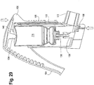
Figs. 27, 28 ,60 and 61 , theMDI 112 is inserted into theaperture carrier MDI 112 is fully seated in thecarrier housing carrier Figs. 29 and62 to reduce the height of theMDI applicator housing 106 and thecarrier 108 are compressed until aledge housing 106 comes in contact with thecanister 114 of theMDI 112. Referring toFig. 62 , the lever includes astop 308 that engages the top of thecanister 114 when setting the correct height for the boot of theMDI 112. - It will be appreciated that the process of adjusting a distance between the
housing carrier MDI applicator Figs. 30, 31 ,65 and 66 . For example theapplicator 202 may accommodate MDI's between 71.5 mm and 98 mm. - In some implementations, the distance between the
housing carrier adjuster Figs. 32 and 33 , a distance between thehousing carrier adjuster teeth carrier complementary teeth adjuster housing carrier housing carrier - Referring to
Figs. 34, 35 ,63 and65 , once the height of theMDI applicator MDI 112, a user may apply a force to thelever MDI 112 is securely positioned in thecarrier lever housing carrier post lever canister 114 of theMDI 112. When thestem 136 of theMDI 112 is compressed enough to open an internal valve, a pressurized medication solution is released from thecanister 114 through thestem 136. The medication solution is released into thenozzle 138 where it forms an aerosol plume as it enters the atmosphere. - When the
MDI applicator MDI applicator MDI 112. As shown inFigs. 36, 37 ,67 and 68 , to move theMDI applicator adjuster adjuster housing carrier - After moving the
adjuster lever housing Fig. 37 . Because thehousing carrier post lever canister 114 of theMDI 112, the force on thelever housing carrier MDI applicator lever housing carrier lever stem 136 of theMDI 112 to compress. After moving thelever adjuster lever housing carrier -
Figures 38 and 39 illustrate another implementation of aMDI applicator 102. In the MDI applicator ofFigs. 38 and 39 , theadjuster 110 is a pivot adjuster that may be pivoted between a locked and an unlocked position. -
Figs. 40A, 40B, 41A, and 41B are drawings illustrating a two-position lever 104 of aMDI applicator 102. As shown inFigs. 40A and 40B , the two-position lever 104 provides for thelever 104 to be in a first position when theMDI applicator 102 is in a closed position. However, when theMDI applicator 102 is in use, thelever 104 slides to a second position as shown inFigs. 41A and 41B to provide more leverage in creating a downward force against thecanister 114 of aMDI 112. It will be appreciated that aMDI applicator 102 with a two-position lever 104 may provide for a morecompact MDI applicator 102 when not in use. -
Fig. 42 is an illustration of another implementation of aMDI applicator 102. In this implementation, theMDI applicator 102 does not include anadjuster 110 that may be moved between a locked and an unlocked position. Instead, thehousing 106 and thecarrier 108 are in telescopic communication with each other such that thehousing 106 and thecarrier 108 may be locked into discrete positions. -
Fig. 43 is an illustration of yet another implementation of a MDI applicator. In the illustrated implementations, theadjuster 110 is an adjustment rack that may be moved between a locked and an unlocked position by means of aide spring levers 142. -
Figs. 44-49 illustrate further implementations of aMDI applicator 102, which, however, do not fall under the scope of the appended claims, and therefore do not form part of the present invention. In the illustrated implementations, theMDI applicator 102 does not include acarrier 108 and anadjuster 110. Instead, thehousing 106 is secured to a boot of aMDI 112 through the use of an adhesive such as double-sided tape or a hook and loop attachment system. Thelever 104 is pivotally connected to thehousing 106 as described above. -
Figs. 50A, 50B, and 50C illustrate another implementation of a MDI applicator, which, however, does not fall under the scope of the appended claims, and therefore does not form part of the present invention. In the implementation ofFigs. 50A, 50B, and 50C , the MDI applicator includes alever 104 and acircular housing 106. The circular housing is configured to receive acanister 114 of aMDI 112 and secure thehousing 106 against theMDI 112. Additionally, thehousing 106 andlever 104 are configured to position the canister against thepost 134 of thelever 104 when thehousing 106 receives thecanister 114 of theMDI 112. - The
lever 104 may move between two positions. In a first position, thelever 104 is extended away from thehousing 106. When thelever 104 is in the first position, thelever 104 operates similar to described above. When a force is applied to thelever 104, thepost 134 of thelever 104 transfers the force into a downward force against thecanister 114 of theMDI 112. Because thehousing 106 is secured to theMDI 112, the downward force against thecanister 114 causes theMDI 112 to actuate and release aerosolized medicine. - In a second position, the
lever 104 is moved towards thehousing 106 and locked for storage. It will be appreciated that when thelever 104 is in a locked position, the lever may not transfer a force to actuate theMDI 112. -
Figs. 1-50 illustrate implementations of MDI applicators that provide a lever to assist a patient in actuating a MDI. The lever transfers forces applied to the lever to a canister of a MDI, thereby causing the MDI to dispense aerosolized medicine for inhalation by a patient. - The embodiments of the invention disclosed herein are presently considered to be preferred, various changes and modifications can be made without departing from the scope of the invention defined by the appended claims. As noted, the discussion above is descriptive, illustrative and exemplary and is not to be taken as limiting the scope defined by any appended claims, and all changes that come within the meaning and range of equivalents are intended to be embraced therein.
Claims (4)
- A metered dose inhaler ("MDI") applicator (102, 202) comprising:a carrier (108, 208) defining an aperture (116, 216) configured to receive a boot of a metered dose inhaler (112);a housing (106, 206) configured to be assembled with the carrier, wherein when assembled with the carrier, the housing and the carrier are configured to move in a vertical direction within the MDI applicator relative to one another; and a lever (104, 204) pivotally connected to the housing for assisting a patient in actuating the metered dose inhaler (112);wherein when the MDI is positioned within the carrier, the lever is configured to transfer a force applied to the lever to a canister (114) of the MDI and to actuate the MDI to dispense an aerosolized medicine.
- The MDI applicator of claim 1, further comprising:an adjuster (110, 210) configured to move between a locked position and an unlocked position, wherein when the adjuster is in the locked position the adjuster is configured to prevent the carrier and the housing from moving in one or more direction relative to one another.
- The MDI applicator of claim 2, wherein the adjuster defines at least one tooth (126, 226) and the carrier defines a complementary set of teeth (124, 224), and wherein the at least one tooth of the adjuster engages at least a portion of the set of teeth of the carrier when the adjuster is in the locked position.
- The MDI applicator of claim 2, wherein when the adjuster is in the locked position, the adjuster prevents a height of the MDI applicator from increasing while allowing a height of the MDI applicator to decrease.
Applications Claiming Priority (2)
| Application Number | Priority Date | Filing Date | Title |
|---|---|---|---|
| US201361781828P | 2013-03-14 | 2013-03-14 | |
| PCT/IB2014/000291 WO2014140724A1 (en) | 2013-03-14 | 2014-03-11 | Metered dose inhaler applicator |
Publications (3)
| Publication Number | Publication Date |
|---|---|
| EP2983773A1 EP2983773A1 (en) | 2016-02-17 |
| EP2983773A4 EP2983773A4 (en) | 2016-11-23 |
| EP2983773B1 true EP2983773B1 (en) | 2018-03-07 |
Family
ID=51535944
Family Applications (1)
| Application Number | Title | Priority Date | Filing Date |
|---|---|---|---|
| EP14764025.4A Active EP2983773B1 (en) | 2013-03-14 | 2014-03-11 | Metered dose inhaler applicator |
Country Status (5)
| Country | Link |
|---|---|
| US (2) | US9931481B2 (en) |
| EP (1) | EP2983773B1 (en) |
| CA (2) | CA3056509C (en) |
| ES (1) | ES2666135T3 (en) |
| WO (1) | WO2014140724A1 (en) |
Families Citing this family (17)
| Publication number | Priority date | Publication date | Assignee | Title |
|---|---|---|---|---|
| USD737954S1 (en) * | 2013-08-20 | 2015-09-01 | Boehringer Ingelheim Vetmedica Gmbh | Aerosol device for large animals |
| US12485235B2 (en) | 2016-03-21 | 2025-12-02 | University Of Cape Town | Assistive device for an inhaler |
| GB2548569A (en) * | 2016-03-21 | 2017-09-27 | Univ Cape Town | An assistive device for an inhaler |
| CN109152891B (en) | 2016-03-24 | 2022-11-08 | 特鲁德尔医学国际公司 | Respiratory care system with electronic indicator |
| ES2966349T3 (en) | 2016-05-19 | 2024-04-22 | Trudell Medical Int | Holding chamber with smart valve |
| ES2988939T3 (en) | 2016-07-08 | 2024-11-22 | Trudell Medical Int Inc | Intelligent Oscillating Positive Expiratory Pressure Device |
| CN110049795B (en) | 2016-12-09 | 2022-07-19 | 特鲁德尔医学国际公司 | Intelligent atomizer |
| US11666801B2 (en) | 2018-01-04 | 2023-06-06 | Trudell Medical International | Smart oscillating positive expiratory pressure device |
| EP3801714B1 (en) | 2018-06-04 | 2026-01-28 | Trudell Medical International Inc. | Smart valved holding chamber |
| CN109646772A (en) * | 2018-12-17 | 2019-04-19 | 中国人民解放军陆军军医大学第附属医院 | A kind of children atomizing device |
| JP7250317B2 (en) * | 2019-03-18 | 2023-04-03 | 学校法人日本大学 | drug inhaler |
| AU2020316731B2 (en) | 2019-07-24 | 2025-07-10 | Trudell Medical International Inc. | Portable holding chamber |
| WO2021038467A1 (en) | 2019-08-27 | 2021-03-04 | Trudell Medical International | Smart oscillating positive expiratory pressure device |
| US12539376B2 (en) | 2019-10-03 | 2026-02-03 | 1000739373 Ontario Ltd. | Inhaler |
| CN111437475A (en) * | 2020-05-07 | 2020-07-24 | 温州市中心医院 | Aerosol auxiliary device applied to respiratory system disease patient |
| GB2597463B (en) * | 2020-07-22 | 2024-06-12 | Batterbee Paul | Inhalever |
| USD1010101S1 (en) | 2020-09-18 | 2024-01-02 | Trudell Medical International | Holding chamber |
Family Cites Families (37)
| Publication number | Priority date | Publication date | Assignee | Title |
|---|---|---|---|---|
| US3405843A (en) | 1966-11-23 | 1968-10-15 | Cornelius B. Watson Jr. | Container-dispenser for collapsible tubes |
| US3456645A (en) | 1967-01-19 | 1969-07-22 | Dart Ind Inc | Inhalation-actuated aerosol dispensing device |
| GB1383761A (en) * | 1971-02-25 | 1974-02-12 | Woodcraft Dc | Inhalation device for use with an aerosol container |
| US4079862A (en) | 1975-02-03 | 1978-03-21 | Fegley Charles R | Chemical dispensing anti-burglary booby trap device |
| US3994421A (en) * | 1975-09-29 | 1976-11-30 | American Cyanamid Company | Unitary therapeutic aerosol dispenser |
| US4077548A (en) | 1976-12-27 | 1978-03-07 | Beard Walter C | Trigger actuator for dispensing pumps with saddle pull-down |
| US4324348A (en) | 1980-01-18 | 1982-04-13 | Minnetonka, Inc. | Dispenser for dispensing liquid from a replaceable container |
| US4402430A (en) * | 1980-09-29 | 1983-09-06 | Alfred F. Washburn | Mechanism for dispensing chemicals from a pressurized container |
| US4771769A (en) | 1982-12-20 | 1988-09-20 | Schering Corporation | Hand held metered spray dispenser |
| NZ212911A (en) * | 1984-07-31 | 1988-06-30 | Glaxo Group Ltd | Aerosol dispensing device; actuator lever acts when cover in open position |
| US4834083A (en) * | 1988-05-12 | 1989-05-30 | Minnesota Mining And Manufacturing Company | Aerosol device |
| GB9020555D0 (en) * | 1990-09-20 | 1990-10-31 | Bespak Plc | Dispensing apparatus |
| US5027808A (en) * | 1990-10-31 | 1991-07-02 | Tenax Corporation | Breath-activated inhalation device |
| GB9217545D0 (en) * | 1992-08-18 | 1992-09-30 | Minnesota Mining & Mfg | Inhalation device |
| US5377869A (en) * | 1992-08-27 | 1995-01-03 | Weiss; Stephan | Pump dispenser with movable bottle |
| DE4436051C2 (en) | 1994-10-10 | 1996-08-14 | Boehringer Ingelheim Kg | Device for actuating aerosol dispensers |
| US20040237961A1 (en) * | 1995-06-08 | 2004-12-02 | Snow John Medlin | Inhalation actuated device for use with metered dose inhalers (MDIs) |
| US5904139A (en) * | 1997-03-28 | 1999-05-18 | Hauser; Stephen G. | Breath coordinated inhaler |
| SE9801078D0 (en) * | 1998-03-27 | 1998-03-27 | Shl Medical Ab | Inhaler |
| US6397837B1 (en) | 1999-07-22 | 2002-06-04 | Martin W. Ferris | Inhaler assistive device |
| AR026914A1 (en) * | 1999-12-11 | 2003-03-05 | Glaxo Group Ltd | MEDICINAL DISTRIBUTOR |
| AU2002345757A1 (en) * | 2001-06-11 | 2002-12-23 | Glaxo Group Limited | Medicament dispenser for containers of varying sizes |
| GB0130284D0 (en) * | 2001-12-19 | 2002-02-06 | Glaxo Group Ltd | Medicament dispenser |
| GB0217199D0 (en) * | 2002-07-25 | 2002-09-04 | Glaxo Group Ltd | Medicament dispenser |
| AU2006225241B2 (en) * | 2003-09-24 | 2008-07-17 | Tianda Pharmaceuticals (Australia) Pty Limited | Medication Holder |
| CN1901958B (en) * | 2003-11-03 | 2011-03-09 | 葛兰素集团有限公司 | Fluid distribution device |
| US20060137681A1 (en) * | 2004-12-28 | 2006-06-29 | Ric Investments, Llc. | Actuator for a metered dose inhaler |
| WO2007041669A2 (en) * | 2005-10-04 | 2007-04-12 | Sp Medical Llc | Metered dose inhaler having spacing device |
| US8225790B2 (en) * | 2007-01-02 | 2012-07-24 | Astrazeneca Ab | Inhaler 624 |
| ES2606977T3 (en) * | 2007-08-21 | 2017-03-28 | Glaxo Group Limited | Medication distributor |
| ES2423587T3 (en) * | 2008-07-10 | 2013-09-23 | Bang & Olufsen Medicom A/S | Inhaler and its operation procedure |
| GB2461752B (en) * | 2008-07-14 | 2013-04-17 | Neo Inhalation Products Ltd | Metered dose inhaler |
| CA2781313C (en) * | 2009-12-23 | 2019-09-17 | Map Pharmaceuticals, Inc. | Enhanced eductor design |
| USD683443S1 (en) * | 2011-12-06 | 2013-05-28 | Anthony J. Mullane | Inhaler assist device |
| US8695589B2 (en) * | 2011-12-06 | 2014-04-15 | Anthony J. Mullane | Inhaler assist device |
| EP2638925B1 (en) * | 2012-03-15 | 2017-04-12 | Relevo Limited | Actuator device for inhalers |
| PT3035887T (en) * | 2013-08-20 | 2020-04-02 | Boehringer Ingelheim Vetmedica Gmbh | INHALER |
-
2014
- 2014-03-11 EP EP14764025.4A patent/EP2983773B1/en active Active
- 2014-03-11 ES ES14764025.4T patent/ES2666135T3/en active Active
- 2014-03-11 CA CA3056509A patent/CA3056509C/en active Active
- 2014-03-11 WO PCT/IB2014/000291 patent/WO2014140724A1/en not_active Ceased
- 2014-03-11 CA CA2914227A patent/CA2914227C/en active Active
- 2014-03-14 US US14/212,461 patent/US9931481B2/en active Active
-
2015
- 2015-09-09 US US14/849,083 patent/US10143812B2/en active Active
Non-Patent Citations (1)
| Title |
|---|
| None * |
Also Published As
| Publication number | Publication date |
|---|---|
| US20160129206A1 (en) | 2016-05-12 |
| US20140318534A1 (en) | 2014-10-30 |
| EP2983773A1 (en) | 2016-02-17 |
| CA2914227C (en) | 2019-11-12 |
| WO2014140724A1 (en) | 2014-09-18 |
| EP2983773A4 (en) | 2016-11-23 |
| CA3056509A1 (en) | 2014-09-18 |
| CA3056509C (en) | 2021-11-16 |
| US9931481B2 (en) | 2018-04-03 |
| CA2914227A1 (en) | 2014-09-18 |
| US10143812B2 (en) | 2018-12-04 |
| ES2666135T3 (en) | 2018-05-03 |
Similar Documents
| Publication | Publication Date | Title |
|---|---|---|
| EP2983773B1 (en) | Metered dose inhaler applicator | |
| US20220323699A1 (en) | Dose Counter for Inhaler Having An Anti-Reverse Rotation Actuator | |
| CN109069767B (en) | Device for dispensing a fluid product with synchronized dispensing and inhalation | |
| EP2300084B1 (en) | An inhaler and a method of operating it | |
| US12303639B2 (en) | Device for inhalation-synchronised dispensing of a fluid product | |
| EP0660731B1 (en) | Inhalation device | |
| CN113382762B (en) | Device for dispensing a fluid product in synchronism with inhalation and method for assembling a device | |
| US10058662B2 (en) | Device for dispensing fluid product | |
| US11547814B2 (en) | Device for the dispensing of a fluid product synchronised with inhalation | |
| EP1267977B1 (en) | Powder inhaler | |
| CN113382760A (en) | Device for dispensing a fluid product in synchronism with inhalation | |
| US11980712B2 (en) | Device for inhalation-synchronized dispensing of a fluid product | |
| US20150083128A1 (en) | Device for dispensing fluid product | |
| TWI903077B (en) | Inhaler with an adherence/compliance monitor | |
| US11992609B2 (en) | Device for inhalation-synchronized dispensing of a fluid product | |
| KR20100134599A (en) | Injection device with horizontal moving part |
Legal Events
| Date | Code | Title | Description |
|---|---|---|---|
| PUAI | Public reference made under article 153(3) epc to a published international application that has entered the european phase |
Free format text: ORIGINAL CODE: 0009012 |
|
| 17P | Request for examination filed |
Effective date: 20151217 |
|
| AK | Designated contracting states |
Kind code of ref document: A1 Designated state(s): AL AT BE BG CH CY CZ DE DK EE ES FI FR GB GR HR HU IE IS IT LI LT LU LV MC MK MT NL NO PL PT RO RS SE SI SK SM TR |
|
| AX | Request for extension of the european patent |
Extension state: BA ME |
|
| DAX | Request for extension of the european patent (deleted) | ||
| A4 | Supplementary search report drawn up and despatched |
Effective date: 20161025 |
|
| RIC1 | Information provided on ipc code assigned before grant |
Ipc: A61M 15/00 20060101AFI20161019BHEP |
|
| GRAP | Despatch of communication of intention to grant a patent |
Free format text: ORIGINAL CODE: EPIDOSNIGR1 |
|
| INTG | Intention to grant announced |
Effective date: 20170927 |
|
| GRAS | Grant fee paid |
Free format text: ORIGINAL CODE: EPIDOSNIGR3 |
|
| GRAA | (expected) grant |
Free format text: ORIGINAL CODE: 0009210 |
|
| AK | Designated contracting states |
Kind code of ref document: B1 Designated state(s): AL AT BE BG CH CY CZ DE DK EE ES FI FR GB GR HR HU IE IS IT LI LT LU LV MC MK MT NL NO PL PT RO RS SE SI SK SM TR |
|
| REG | Reference to a national code |
Ref country code: GB Ref legal event code: FG4D |
|
| REG | Reference to a national code |
Ref country code: CH Ref legal event code: EP Ref country code: AT Ref legal event code: REF Ref document number: 975891 Country of ref document: AT Kind code of ref document: T Effective date: 20180315 |
|
| REG | Reference to a national code |
Ref country code: NL Ref legal event code: FP |
|
| REG | Reference to a national code |
Ref country code: IE Ref legal event code: FG4D |
|
| REG | Reference to a national code |
Ref country code: DE Ref legal event code: R096 Ref document number: 602014022080 Country of ref document: DE Ref country code: FR Ref legal event code: PLFP Year of fee payment: 5 |
|
| REG | Reference to a national code |
Ref country code: ES Ref legal event code: FG2A Ref document number: 2666135 Country of ref document: ES Kind code of ref document: T3 Effective date: 20180503 |
|
| REG | Reference to a national code |
Ref country code: LT Ref legal event code: MG4D |
|
| PG25 | Lapsed in a contracting state [announced via postgrant information from national office to epo] |
Ref country code: LT Free format text: LAPSE BECAUSE OF FAILURE TO SUBMIT A TRANSLATION OF THE DESCRIPTION OR TO PAY THE FEE WITHIN THE PRESCRIBED TIME-LIMIT Effective date: 20180307 Ref country code: CY Free format text: LAPSE BECAUSE OF FAILURE TO SUBMIT A TRANSLATION OF THE DESCRIPTION OR TO PAY THE FEE WITHIN THE PRESCRIBED TIME-LIMIT Effective date: 20180307 Ref country code: HR Free format text: LAPSE BECAUSE OF FAILURE TO SUBMIT A TRANSLATION OF THE DESCRIPTION OR TO PAY THE FEE WITHIN THE PRESCRIBED TIME-LIMIT Effective date: 20180307 Ref country code: FI Free format text: LAPSE BECAUSE OF FAILURE TO SUBMIT A TRANSLATION OF THE DESCRIPTION OR TO PAY THE FEE WITHIN THE PRESCRIBED TIME-LIMIT Effective date: 20180307 Ref country code: NO Free format text: LAPSE BECAUSE OF FAILURE TO SUBMIT A TRANSLATION OF THE DESCRIPTION OR TO PAY THE FEE WITHIN THE PRESCRIBED TIME-LIMIT Effective date: 20180607 |
|
| REG | Reference to a national code |
Ref country code: AT Ref legal event code: MK05 Ref document number: 975891 Country of ref document: AT Kind code of ref document: T Effective date: 20180307 |
|
| PG25 | Lapsed in a contracting state [announced via postgrant information from national office to epo] |
Ref country code: RS Free format text: LAPSE BECAUSE OF FAILURE TO SUBMIT A TRANSLATION OF THE DESCRIPTION OR TO PAY THE FEE WITHIN THE PRESCRIBED TIME-LIMIT Effective date: 20180307 Ref country code: GR Free format text: LAPSE BECAUSE OF FAILURE TO SUBMIT A TRANSLATION OF THE DESCRIPTION OR TO PAY THE FEE WITHIN THE PRESCRIBED TIME-LIMIT Effective date: 20180608 Ref country code: BG Free format text: LAPSE BECAUSE OF FAILURE TO SUBMIT A TRANSLATION OF THE DESCRIPTION OR TO PAY THE FEE WITHIN THE PRESCRIBED TIME-LIMIT Effective date: 20180607 Ref country code: SE Free format text: LAPSE BECAUSE OF FAILURE TO SUBMIT A TRANSLATION OF THE DESCRIPTION OR TO PAY THE FEE WITHIN THE PRESCRIBED TIME-LIMIT Effective date: 20180307 Ref country code: LV Free format text: LAPSE BECAUSE OF FAILURE TO SUBMIT A TRANSLATION OF THE DESCRIPTION OR TO PAY THE FEE WITHIN THE PRESCRIBED TIME-LIMIT Effective date: 20180307 |
|
| PG25 | Lapsed in a contracting state [announced via postgrant information from national office to epo] |
Ref country code: AL Free format text: LAPSE BECAUSE OF FAILURE TO SUBMIT A TRANSLATION OF THE DESCRIPTION OR TO PAY THE FEE WITHIN THE PRESCRIBED TIME-LIMIT Effective date: 20180307 Ref country code: PL Free format text: LAPSE BECAUSE OF FAILURE TO SUBMIT A TRANSLATION OF THE DESCRIPTION OR TO PAY THE FEE WITHIN THE PRESCRIBED TIME-LIMIT Effective date: 20180307 Ref country code: RO Free format text: LAPSE BECAUSE OF FAILURE TO SUBMIT A TRANSLATION OF THE DESCRIPTION OR TO PAY THE FEE WITHIN THE PRESCRIBED TIME-LIMIT Effective date: 20180307 Ref country code: EE Free format text: LAPSE BECAUSE OF FAILURE TO SUBMIT A TRANSLATION OF THE DESCRIPTION OR TO PAY THE FEE WITHIN THE PRESCRIBED TIME-LIMIT Effective date: 20180307 |
|
| REG | Reference to a national code |
Ref country code: CH Ref legal event code: PL |
|
| PG25 | Lapsed in a contracting state [announced via postgrant information from national office to epo] |
Ref country code: SK Free format text: LAPSE BECAUSE OF FAILURE TO SUBMIT A TRANSLATION OF THE DESCRIPTION OR TO PAY THE FEE WITHIN THE PRESCRIBED TIME-LIMIT Effective date: 20180307 Ref country code: CZ Free format text: LAPSE BECAUSE OF FAILURE TO SUBMIT A TRANSLATION OF THE DESCRIPTION OR TO PAY THE FEE WITHIN THE PRESCRIBED TIME-LIMIT Effective date: 20180307 Ref country code: SM Free format text: LAPSE BECAUSE OF FAILURE TO SUBMIT A TRANSLATION OF THE DESCRIPTION OR TO PAY THE FEE WITHIN THE PRESCRIBED TIME-LIMIT Effective date: 20180307 Ref country code: AT Free format text: LAPSE BECAUSE OF FAILURE TO SUBMIT A TRANSLATION OF THE DESCRIPTION OR TO PAY THE FEE WITHIN THE PRESCRIBED TIME-LIMIT Effective date: 20180307 |
|
| REG | Reference to a national code |
Ref country code: BE Ref legal event code: MM Effective date: 20180331 Ref country code: DE Ref legal event code: R097 Ref document number: 602014022080 Country of ref document: DE |
|
| REG | Reference to a national code |
Ref country code: IE Ref legal event code: MM4A |
|
| PG25 | Lapsed in a contracting state [announced via postgrant information from national office to epo] |
Ref country code: LU Free format text: LAPSE BECAUSE OF NON-PAYMENT OF DUE FEES Effective date: 20180311 Ref country code: PT Free format text: LAPSE BECAUSE OF FAILURE TO SUBMIT A TRANSLATION OF THE DESCRIPTION OR TO PAY THE FEE WITHIN THE PRESCRIBED TIME-LIMIT Effective date: 20180709 |
|
| PLBE | No opposition filed within time limit |
Free format text: ORIGINAL CODE: 0009261 |
|
| STAA | Information on the status of an ep patent application or granted ep patent |
Free format text: STATUS: NO OPPOSITION FILED WITHIN TIME LIMIT |
|
| PG25 | Lapsed in a contracting state [announced via postgrant information from national office to epo] |
Ref country code: IE Free format text: LAPSE BECAUSE OF NON-PAYMENT OF DUE FEES Effective date: 20180311 Ref country code: MC Free format text: LAPSE BECAUSE OF FAILURE TO SUBMIT A TRANSLATION OF THE DESCRIPTION OR TO PAY THE FEE WITHIN THE PRESCRIBED TIME-LIMIT Effective date: 20180307 Ref country code: DK Free format text: LAPSE BECAUSE OF FAILURE TO SUBMIT A TRANSLATION OF THE DESCRIPTION OR TO PAY THE FEE WITHIN THE PRESCRIBED TIME-LIMIT Effective date: 20180307 |
|
| 26N | No opposition filed |
Effective date: 20181210 |
|
| PG25 | Lapsed in a contracting state [announced via postgrant information from national office to epo] |
Ref country code: SI Free format text: LAPSE BECAUSE OF FAILURE TO SUBMIT A TRANSLATION OF THE DESCRIPTION OR TO PAY THE FEE WITHIN THE PRESCRIBED TIME-LIMIT Effective date: 20180307 Ref country code: CH Free format text: LAPSE BECAUSE OF NON-PAYMENT OF DUE FEES Effective date: 20180331 Ref country code: BE Free format text: LAPSE BECAUSE OF NON-PAYMENT OF DUE FEES Effective date: 20180331 Ref country code: LI Free format text: LAPSE BECAUSE OF NON-PAYMENT OF DUE FEES Effective date: 20180331 |
|
| PG25 | Lapsed in a contracting state [announced via postgrant information from national office to epo] |
Ref country code: MT Free format text: LAPSE BECAUSE OF NON-PAYMENT OF DUE FEES Effective date: 20180311 |
|
| PG25 | Lapsed in a contracting state [announced via postgrant information from national office to epo] |
Ref country code: TR Free format text: LAPSE BECAUSE OF FAILURE TO SUBMIT A TRANSLATION OF THE DESCRIPTION OR TO PAY THE FEE WITHIN THE PRESCRIBED TIME-LIMIT Effective date: 20180307 |
|
| PG25 | Lapsed in a contracting state [announced via postgrant information from national office to epo] |
Ref country code: HU Free format text: LAPSE BECAUSE OF FAILURE TO SUBMIT A TRANSLATION OF THE DESCRIPTION OR TO PAY THE FEE WITHIN THE PRESCRIBED TIME-LIMIT; INVALID AB INITIO Effective date: 20140311 Ref country code: MK Free format text: LAPSE BECAUSE OF NON-PAYMENT OF DUE FEES Effective date: 20180307 |
|
| PG25 | Lapsed in a contracting state [announced via postgrant information from national office to epo] |
Ref country code: IS Free format text: LAPSE BECAUSE OF FAILURE TO SUBMIT A TRANSLATION OF THE DESCRIPTION OR TO PAY THE FEE WITHIN THE PRESCRIBED TIME-LIMIT Effective date: 20180707 |
|
| REG | Reference to a national code |
Ref country code: DE Ref legal event code: R081 Ref document number: 602014022080 Country of ref document: DE Owner name: TRUDELL MEDICAL INTERNATIONAL INC., LONDON, CA Free format text: FORMER OWNER: TRUDELL MEDICAL INTERNATIONAL, LONDON, ONTARIO, CA |
|
| REG | Reference to a national code |
Ref country code: GB Ref legal event code: 732E Free format text: REGISTERED BETWEEN 20240425 AND 20240501 |
|
| REG | Reference to a national code |
Ref country code: NL Ref legal event code: PD Owner name: TRUDELL MEDICAL INTERNATIONAL INC.; CA Free format text: DETAILS ASSIGNMENT: CHANGE OF OWNER(S), ASSIGNMENT; FORMER OWNER NAME: TRUDELL MEDICAL INTERNATIONAL Effective date: 20241007 |
|
| PGFP | Annual fee paid to national office [announced via postgrant information from national office to epo] |
Ref country code: ES Payment date: 20250401 Year of fee payment: 12 |
|
| PGFP | Annual fee paid to national office [announced via postgrant information from national office to epo] |
Ref country code: IT Payment date: 20250327 Year of fee payment: 12 |
|
| PGFP | Annual fee paid to national office [announced via postgrant information from national office to epo] |
Ref country code: GB Payment date: 20260330 Year of fee payment: 13 |
|
| PGFP | Annual fee paid to national office [announced via postgrant information from national office to epo] |
Ref country code: DE Payment date: 20260326 Year of fee payment: 13 |
|
| PGFP | Annual fee paid to national office [announced via postgrant information from national office to epo] |
Ref country code: NL Payment date: 20260330 Year of fee payment: 13 |
|
| PGFP | Annual fee paid to national office [announced via postgrant information from national office to epo] |
Ref country code: FR Payment date: 20260330 Year of fee payment: 13 |