EP2962288B1 - Tag housing assembly for attachment to a bottle neck - Google Patents
Tag housing assembly for attachment to a bottle neck Download PDFInfo
- Publication number
- EP2962288B1 EP2962288B1 EP14757059.2A EP14757059A EP2962288B1 EP 2962288 B1 EP2962288 B1 EP 2962288B1 EP 14757059 A EP14757059 A EP 14757059A EP 2962288 B1 EP2962288 B1 EP 2962288B1
- Authority
- EP
- European Patent Office
- Prior art keywords
- housing
- tag
- bottle
- housing assembly
- neck
- Prior art date
- Legal status (The legal status is an assumption and is not a legal conclusion. Google has not performed a legal analysis and makes no representation as to the accuracy of the status listed.)
- Active
Links
Images




Classifications
-
- G—PHYSICS
- G06—COMPUTING OR CALCULATING; COUNTING
- G06K—GRAPHICAL DATA READING; PRESENTATION OF DATA; RECORD CARRIERS; HANDLING RECORD CARRIERS
- G06K19/00—Record carriers for use with machines and with at least a part designed to carry digital markings
- G06K19/06—Record carriers for use with machines and with at least a part designed to carry digital markings characterised by the kind of the digital marking, e.g. shape, nature, code
- G06K19/067—Record carriers with conductive marks, printed circuits or semiconductor circuit elements, e.g. credit or identity cards also with resonating or responding marks without active components
- G06K19/07—Record carriers with conductive marks, printed circuits or semiconductor circuit elements, e.g. credit or identity cards also with resonating or responding marks without active components with integrated circuit chips
- G06K19/077—Constructional details, e.g. mounting of circuits in the carrier
- G06K19/07749—Constructional details, e.g. mounting of circuits in the carrier the record carrier being capable of non-contact communication, e.g. constructional details of the antenna of a non-contact smart card
- G06K19/07758—Constructional details, e.g. mounting of circuits in the carrier the record carrier being capable of non-contact communication, e.g. constructional details of the antenna of a non-contact smart card arrangements for adhering the record carrier to further objects or living beings, functioning as an identification tag
-
- B—PERFORMING OPERATIONS; TRANSPORTING
- B65—CONVEYING; PACKING; STORING; HANDLING THIN OR FILAMENTARY MATERIAL
- B65D—CONTAINERS FOR STORAGE OR TRANSPORT OF ARTICLES OR MATERIALS, e.g. BAGS, BARRELS, BOTTLES, BOXES, CANS, CARTONS, CRATES, DRUMS, JARS, TANKS, HOPPERS, FORWARDING CONTAINERS; ACCESSORIES, CLOSURES, OR FITTINGS THEREFOR; PACKAGING ELEMENTS; PACKAGES
- B65D23/00—Details of bottles or jars not otherwise provided for
- B65D23/12—Means for the attachment of smaller articles
- B65D23/14—Means for the attachment of smaller articles of tags, labels, cards, coupons, decorations or the like
-
- E—FIXED CONSTRUCTIONS
- E05—LOCKS; KEYS; WINDOW OR DOOR FITTINGS; SAFES
- E05B—LOCKS; ACCESSORIES THEREFOR; HANDCUFFS
- E05B73/00—Devices for locking portable objects against unauthorised removal; Miscellaneous locking devices
- E05B73/0017—Anti-theft devices, e.g. tags or monitors, fixed to articles, e.g. clothes, and to be removed at the check-out of shops
- E05B73/0041—Anti-theft devices, e.g. tags or monitors, fixed to articles, e.g. clothes, and to be removed at the check-out of shops for essentially round objects, e.g. bottles or racket handles
-
- G—PHYSICS
- G06—COMPUTING OR CALCULATING; COUNTING
- G06K—GRAPHICAL DATA READING; PRESENTATION OF DATA; RECORD CARRIERS; HANDLING RECORD CARRIERS
- G06K19/00—Record carriers for use with machines and with at least a part designed to carry digital markings
- G06K19/06—Record carriers for use with machines and with at least a part designed to carry digital markings characterised by the kind of the digital marking, e.g. shape, nature, code
- G06K19/067—Record carriers with conductive marks, printed circuits or semiconductor circuit elements, e.g. credit or identity cards also with resonating or responding marks without active components
- G06K19/07—Record carriers with conductive marks, printed circuits or semiconductor circuit elements, e.g. credit or identity cards also with resonating or responding marks without active components with integrated circuit chips
- G06K19/077—Constructional details, e.g. mounting of circuits in the carrier
- G06K19/0772—Physical layout of the record carrier
-
- B—PERFORMING OPERATIONS; TRANSPORTING
- B65—CONVEYING; PACKING; STORING; HANDLING THIN OR FILAMENTARY MATERIAL
- B65D—CONTAINERS FOR STORAGE OR TRANSPORT OF ARTICLES OR MATERIALS, e.g. BAGS, BARRELS, BOTTLES, BOXES, CANS, CARTONS, CRATES, DRUMS, JARS, TANKS, HOPPERS, FORWARDING CONTAINERS; ACCESSORIES, CLOSURES, OR FITTINGS THEREFOR; PACKAGING ELEMENTS; PACKAGES
- B65D2203/00—Decoration means, markings, information elements, contents indicators
- B65D2203/10—Transponders
-
- G—PHYSICS
- G08—SIGNALLING
- G08B—SIGNALLING SYSTEMS, e.g. PERSONAL CALLING SYSTEMS; ORDER TELEGRAPHS; ALARM SYSTEMS
- G08B13/00—Burglar, theft or intruder alarms
- G08B13/22—Electrical actuation
- G08B13/24—Electrical actuation by interference with electromagnetic field distribution
- G08B13/2402—Electronic Article Surveillance [EAS], i.e. systems using tags for detecting removal of a tagged item from a secure area, e.g. tags for detecting shoplifting
- G08B13/2428—Tag details
- G08B13/2434—Tag housing and attachment details
Definitions
- the present invention relates generally to housings that accommodate electronic tags such as radio frequency identification (RFID) tags or electronic article surveillance (EAS) tags attached to an extending neck of a bottle. More particularly, the present invention relates to a single component or dual component tag housing, which may be securely attached to the extending neck of a bottle and subsequently removed therefrom. Alternatively, the present invention relates to a one-piece tag housing which may be non-removably attached to the extending neck of a bottle.
- RFID radio frequency identification
- EAS electronic article surveillance
- Electronic tags are used for a wide variety of purposes including the tracking of items that contain the tag, inventory control, security and also provide information that may be electronically readable.
- These tags or markers may include radio frequency identification (RFID) tags or electronic article surveillance (EAS) tags, which include dual resonator (DR) tags and radio frequency (RF) tags.
- RFID radio frequency identification
- EAS electronic article surveillance
- DR dual resonator
- RF radio frequency
- tag housings are shown in commonly assigned U.S. Patent Nos. 8,228,200 ; 8,267,326 ; and commonly assigned U.S. Patent Publication Nos. 2010/0133224 and 2011/0074583 .
- a tag housing may be attachable to the extending neck of a bottle where the extending neck has an undercut.
- Flexible fingers supported within the tag housing engage the undercut.
- the flexible fingers may be tightened onto the bottle neck to secure the tag housing to the bottle neck by use of a surrounding cable tie.
- the cable tie may be tightened around the flexible fingers to urge the fingers inwardly to securely engage the undercut of the bottle neck. This secures the tag housing to the bottle neck.
- the cable tie In order to remove this tag from the bottle neck, the cable tie must be severed releasing the grip of the fingers around the bottle neck.
- tag housing serves adequately for its intended purposes, removal from the bottle neck after the tag housing has served its purpose is difficult and cumbersome as it must be forcibly removed from the bottle neck. This becomes difficult and time consuming for the user who has purchased the bottle with the tag housing in place.
- Other tag housings include movable retaining devices, which can be released using a tool so as to permit removal of the housing from the bottle neck. While these tag housings serve adequately for their intended purposes, the ability to remove the housing from the bottle neck requires the housing to be formed of multiple components, which increases the cost of the housing.
- US 2010/0253524 discloses a tag holder consisting of two section to be assembled together.
- US 2012/0024962 discloses a tag housing lockable to a bottle neck through flexible fingers.
- the present invention is a tag housing assembly for attaching an electronic tag to an extending neck of a bottle with a perimetrical undercut thereabout, as defined in appended claim 1.
- the tag housing, assembly includes a tag housing, at least one electronic tag and a retaining device.
- the tag housing includes a perimetrical exterior side wall extending between a top surface and a base plate to define an interior and an opening extending through the top surface and base plate for receiving the extending neck of the bottle.
- the at least one electronic tag is located in the interior.
- the retaining device extends into the opening and defines an adjustable aperture for engaging the extending neck of the bottle. When the tag housing is in a closed position, the retaining device is secured to the neck of the bottle.
- the retaining device can include a plurality of flexible fingers, wherein each flexible finger extends from the base plate to a distal end for surrounding engagement with the neck of the bottle. Preferably, the flexible fingers extend upwardly from the base plate.
- the retaining device can be either fixedly or movably attached to the base plate so that the adjustable aperture can be increased or decreased to receive a bottle neck inserted through the base plate. After the perimetrical undercut passes through the adjustable aperture, the distal ends of the fingers engage the perimetrical undercut and prevent the tag housing assembly from being removed from the bottle.
- the tag housing assembly can include a first housing and a second housing that are detachably connected or fixedly attached. After the first and second housings are joined together, they can be secured in a locked position, which prevents the tag housing assembly from being removed from the bottle neck.
- the first and second housings are pivotably connected by a hinge on one side of the tag housing and locked together by a latching mechanism on the opposite side.
- the pivoting of the first and second housings bisects the opening.
- the first housing can include a first latching element and the second housing can include a second latching element opposite the hinge.
- the first and second latching elements are first and second latching apertures, respectively. When the tag housing is in the closed position, the first and second latching apertures are aligned and a latching pin is inserted in the first and second latching apertures to lock the tag housing.
- the exterior side wall has a first end and a second end and first and second substantially parallel sides extending therebetween.
- the first housing includes the first end and the first side and the second housing includes the second end and the second side.
- the first housing includes a pair of arms and the second housing includes a pair of passages for receiving the arms.
- Each of the pair of arms has a latch for adjustably securing the arms in the passages and joining the first and second housings. The adjustment of the latch for securing the arms can be used to change the size of the adjustable aperture.
- the retaining device can be an interior wall extending between the top surface and the base plate that defines the opening in the tag housing.
- the interior wall can have a plurality of substantially parallel ribs extending into the opening and perpendicular to the top surface and the base plate.
- the retaining device includes a first section fixedly attached to the base plate and a second section that is movably attached to the base plate. The movement of the second section changes the size of the adjustable aperture.
- the tag housing can include a locking mechanism for locking the movable second section of the retaining device in a fixed position.
- the second section of the retaining device is movable within the housing interior upon application of a removal tool, which moves the second section to change the size of the adjustable aperture.
- the present invention provides a tag housing assembly for attaching at least one electronic tag to an extending neck of a bottle that can have a perimetrical undercut thereabout.
- the housing assembly includes a first housing capable of supporting at least one electronic tag and a second housing capable of supporting at least one electronic tag.
- the first and second housings are detachably coupled to define a substantially round or oval opening therebetween for receiving the extending neck of the bottle.
- Each of the first and second housings includes one or more retaining devices disposed about the opening, which define therebetween an adjustable aperture for accommodating the neck of the bottle therethrough.
- the first and second housings are movable to an attached, clamped position about the bottle neck and subsequently movable to a detached, unclamped position to permit removal of the first and second housings from about the bottle.
- a removal tool can be used to detach the first housing from the second housing.
- the housing assembly includes a first housing capable of supporting at least one electronic tag and a second housing capable of supporting at least one electronic tag.
- the first and second housings each have a top and bottom surface connected by an interior side wall and an exterior side wall.
- the first and second housings are adjustably and detachably coupled to define a substantially round or oval adjustable opening therebetween for receiving the extending neck of the bottle.
- the first housing has a pair of passages for adjustably receiving a pair of arms that extend from the second housing on either side of the opening.
- the first and second housings are movable to one or more attached, clamped positions about the bottle neck, which accommodates different size bottle necks, and subsequently movable to a detached, unclamped position to permit removal of the bottle from the opening.
- the housing assembly includes a first housing capable of supporting at least one electronic tag and a second housing capable of supporting at least one electronic tag.
- the first and second housings each have a top surface, an exterior side wall and an interior side wall.
- the first and second housings are pivotally connected on one side and attachably coupled on the opposing side so that the two housings pivot in a plane that is parallel to the top surface.
- the interior side walls define a substantially round or oval opening therebetween for receiving the extending neck of the bottle.
- a flexible retaining device extends around the opening and defines an adjustable aperture for accommodation around the neck of a bottle.
- the flexible retaining device is formed by a plurality of flexible fingers, which engage the perimetrical undercut of the bottle neck with their distal ends.
- the first and second housings are movable to an attached, coupled or clamped position about the bottle neck and subsequently movable to a detached, unclamped position to permit removal of the bottle from the opening.
- a tag housing assembly 110 is shown in FIGs. 1-4 .
- the tag housing assembly 110 includes an upper housing portion 112, also shown in FIG. 5 ; a lower housing portion 114, also shown in FIG. 7 ; and a movable retaining device 116, also shown in FIG. 6 .
- the upper housing portion 112 is formed by a top surface 111 and a perimetrical side wall 113 extending downwardly from the edges.
- the lower housing portion 114 includes a base plate 119.
- the housing assembly 110 supports one or more electronic tags, such as an EAS tag 115 and/or a RFID tag 117, in an interior thereof.
- the upper housing portion 112 is joined with the lower housing portion 114 and can be secured thereto using a variety of securement techniques, preferably ultrasonic welding around the peripheral rim thereof.
- the upper and lower housing portions 112 and 114 have an aligned central opening 120 therethrough for accommodation over the extending neck 190 of a bottle 192 with a perimetrical indent 194 ( FIG. 3 ).
- the lower housing portion 114 includes a fixed retaining device 122 in the form of a plurality of spaced apart flexible fingers 124 extending approximately half way about the opening 120.
- the lower housing portion 114 also supports a movable retaining device 116 in the interior of housing assembly 110.
- the movable retaining device 116 also includes a plurality of spaced apart flexible fingers 126 extending half way about the opening 120. Together the flexible fingers 124, 126 of the fixed and movable retaining devices 114, 116 define an adjustable aperture 128 for surrounding accommodation of the neck 190 of the bottle 192 extending through opening 120.
- the movable retaining device as shown in FIG. 6 includes a pair of wings 130 and 132 separated by slots 134 and 136.
- the wings are capable of flexing slightly upwardly so that when the retaining device is positioned within the bottom housing portion 114 and moved to a forward position, tabs 138, 139 can be inserted into recesses 140, 142 formed in lower housing portion 114.
- the movable retaining device 116 is adjusted so as to move forward towards the fixed retaining device 122 as shown in FIG. 4 whereupon the movable retaining device 116 is placed in a clamping position with the fixed retaining device 122 to clamp the housing assembly 110 to the neck 190 of bottle 192 beneath undercut 194.
- the housing assembly 110 is fixedly coupled to the neck 190 of the bottle 192.
- the removal tool 160 is shown in FIGs. 8-12 .
- the removal tool 160 includes an upper portion 162 and a lower portion 164, which are ultrasonically or similarly coupled together.
- the lower portion 164 includes a pair of spaced apart rails 166 and 168.
- the rails 166, 168 are inserted into slots 170 and 172 in the base plate 119 of the lower housing portion 114 ( FIGs. 1, 3 ).
- Each of the rails 166, 168 has a tapered lead-in portion 166a and 168a, which engages the tabs 138, 139 of movable retaining device 116 and lift the wings 130 and 132 upwardly and out of their seated engagement with the recesses 140, 142. Thereafter, the back end of the tapered lead-in portions 166a, 168a engages the tabs 138, 139.
- the handle 165 on the removal tool 160 is used to pull backward (in the direction of arrow A- FIG. 12 )) so that it moves back in slots 170 and 172 thereby pulling back on retaining device 116, expanding opening 128 and moving fingers 126 away from clamping engagement with the bottle neck 190. Once this is achieved, the removal tool 160 can be removed from the housing assembly 110 and the housing assembly 110 may be lifted from the bottle neck 190 removing the housing assembly 110 therefrom.
- such a removal tool 160 would be employed at the point of purchase such as a checkout counter after the tag housing 110 attached to the bottle 192 is been scanned at the check-out counter and the information contained on the RFID 117 and/or EAS tags 115 is retrieved and/or the alarm is deactivated.
- a tag housing assembly 210 of the present invention is shown in FIGs. 13 and 15-18 .
- the tag assembly 210 includes a first housing 212 and a second housing 214, which are detachably coupled together to define therebetween an opening 220 for receiving the extending neck 290 of a bottle 292 with a perimetrical undercut 294.
- the first housing 212 includes an upper portion 224 and a lower portion 226.
- the upper portion 212 includes a top surface 211 with a perimetrical side wall 213 extending downwardly from the outer edges.
- the lower portion 214 includes a base plate 219.
- the first housing 212 is designed to accommodate therebetween an electronic tag such as an RFID tag 217.
- the upper portion 224 is coupled to the lower portion 226 by ultrasonic welding or similar attachment techniques.
- the lower portion 226, as shown in FIG. 17 includes a first retaining device 230 which includes a plurality of upwardly extending spaced apart fingers 232. The fingers 232 extend approximately half way about the opening 220 as shown in FIG. 13 .
- FIG. 18 shows the second housing 214 including an upper portion 234 and a lower portion 236.
- the housing portions 234 and 236 accommodate therebetween an electronic tag, such as an EAS tag 215.
- the lower portion 236 includes a base plate 239 and a retaining device 238 having a plurality of upwardly extending flexible fingers 239, which also extends half way about opening 220. Together the flexible fingers 232, 239 of the retaining devices 230, 238 define an adjustable aperture 228 ( FIG. 13 ) for surrounding accommodation of the neck 290 of the bottle 292.
- the first housing 212 includes a pair of extending arms 250, which are designed to be inserted into passages 254 and 256 in the second housing 214.
- Each arm 250 includes a pair of elongate upper and lower spring latches 260, 262, which are deflectable to lockingly couple the first housing 212 to the second housing 214 at one or more locations, as shown in further detail with respect to the description of FIG. 20 hereinbelow.
- the arms 250 also include a stiffening member 266 having a tapered lead-in 266a to help insert and support the first housing 212 and second housing 214 and prevent inadvertent separation of the two housings 212, 214.
- the two housings 212 and 214 are joined together into a closed or clamping position, as shown in FIGs. 15 and 16 .
- the housing assembly 210 can be fixedly coupled to the neck 290 of a bottle 292, such as the one shown in FIG. 14 .
- the fingers 232, 239 engage the neck 290 below the undercut 294 on the bottle 292 and the tag housing assembly 210 can only be removed using the removal tool 280.
- the distal ends of the arms 250 are received in the passages 270 and 272 in the second housing 214 and secured in the clamping position by the spring latches 260, 262.
- the passages 270, 272 are covered by a thin extent of material 270a, 272a that can be ruptured using a removal tool 280 (as described hereinbelow) to remove the tag housing assembly 210 from the bottle 292.
- the removal tool 280 is shown in FIGs. 19 and 20 .
- the removal tool 280 includes a housing body 281 which supports therein a pair of jaw-like upper and lower finger elements 282 and 284.
- the jaw-like finger elements 282, 284 are opposed by a spring 286 that provides spring-opposed actuation.
- the distal tips 282a, 284a puncture the thin material 270a and 272a over the passages 270, 272 of the housing and contact the distal ends of the spring latches 260, 262 on the arms 250 ( FIG. 13 ).
- Tag housing assembly 310 includes a one-piece integrally formed housing 311, which as particularly shown in FIG. 23 includes a perimetrical inner housing wall 312 and a perimetrical outer housing wall 314.
- a planar surface 316 extends between the inner and outer perimetrical walls 312 and 314.
- the planar surface 316, the inner perimetrical wall 312 and outer perimetrical wall 314 define an open ended cavity 318, which accommodates an electronic tag 315.
- the tag 315 may include an EAS or RFID tag, or any similar electronic tag commonly used for such purpose.
- the inner perimetrical wall 312 defines an opening 320 for insertable accommodation of the neck 390 of a bottle 392 ( FIG. 24 ).
- FIG. 23 shows the tag 315 adhesively secured to an inside surface 314a of the outer perimetrical wall 314.
- Other securement techniques may also be employed.
- one side of outer perimetrical wall 314 may be planar to accommodate securement of the tag 315.
- the retaining device 330 is integrally formed with and extend inwardly from the inner perimetrical wall 312.
- the retaining device 330 has a plurality of inwardly directed, resiliently deflectable fingers 332, which are circumferentially spaced apart.
- the fingers 332 of the retaining device 330 extend into the opening 320 defined by inner perimetrical wall 312 and define an adjustable aperture 328 for receipt of the neck 390 of bottle 392.
- the aperture 328 defined by fingers 332 is smaller than the neck 390 of the bottle 392 so that upon insertion of the neck 390 of the bottle 392 into the opening 320 in the tag housing assembly 310, the fingers 332 deflect outwardly to permit passage of the bottle neck 390.
- the fingers 332 are cantilevered from the base of the inner wall 312 ad extend upwardly therefrom.
- the fingers 332 are deflectable outwardly to allow the insertion of the bottle neck 390.
- the deflected fingers 332 tightly grip the bottle neck 390.
- Each of the fingers has a distal extent 337 defining an inwardly directed lip 337a, which is seatable against the undercut 394 of the neck 390 of the bottle 392.
- the construction and arrangement of the fingers 332 permit the fingers to resiliently engage the neck 390 of the bottle 392 and such that the lip 337a non-releasably seats within the undercut 394 of the bottle 392.
- the tag housing assembly 310 Once seated in the undercut 394, the tag housing assembly 310 cannot be removed from the bottle neck 390 by sliding it therealong.
- Such arrangement non-releasably attaches the tag housing assembly 310 to the neck 390 of the bottle 392, preventing non-destructible removal therefrom.
- the tag housing assembly 410 includes an upper housing portion 412 and a lower housing portion 414 that are joined together to define an interior therebetween.
- the upper housing portion 412 has a top surface 411 with a perimetrical side wall 413 extending downwardly from the top surface 411.
- the lower housing portion 414 has a base 419.
- a substantially round or oval opening 420 extends from the top surface 411 of the upper housing portion 412 through the base 419 of the lower housing portion 414 for receiving the neck 490 of a bottle 492 (see FIG. 32 ).
- the housing interior can accommodate an EAS tag 415 and/or a RFID tag 417.
- the lower housing portion 414 has a flexible retaining device 430 extending around the opening 420, which defines an adjustable aperture 428 for accommodation around the neck 490 of a bottle 492.
- the flexible retaining device 430 is formed by a plurality of flexible fingers 432.
- the neck 490 of the bottle 492 is inserted into the opening 420 and the flexible fingers 432 engage the perimetrical undercut 494 of the bottle neck 490 with their distal ends 437.
- One end of the upper housing portion 412 can extend upwardly from the top surface 411 to form an elongated housing portion 416 with a cavity 418 sized for receiving the EAS tag 415 or a RFID tag 417.
- the tag 415, 417 is inserted in to the cavity 418 and then the lower housing portion 414 is attached to the upper housing portion 412 using an adhesive or ultrasonic welding.
- the housing has to be fractured in order to remove the tag(s).
- FIGs. 30, 31, 33 and 34, 35, 37 show embodiments wherein the elongated housing portion 416 extends upwardly from the end of the upper housing portion 412.
- a cover is placed over the elongated housing portion 416 and secured in place using an adhesive or ultrasonic welding.
- the housing assembly 510 includes a first housing 512 and a second housing 514 capable of supporting an EAS tag 515 and/or a RFID tag 517.
- the first and second housings 512, 514 each have a top surface 511a, 511b and bottom surface 519a, 519b connected by an interior side wall 525a, 525b and an exterior side wall 513a, 513b.
- the first and second housings 512, 514 are adjustably and detachably coupled to define a substantially round or oval adjustable opening 520 therebetween for receiving the extending neck of the bottle ( FIG. 42 ).
- the first and second housings 512, 514 can include one or more ribs 527a, 527b disposed on the interior side walls 525a, 525b, respectively, and extending between the top surfaces 511a, 511b and base plates 519a, 519b, which engagingly secure the neck 590 of the bottle 592 therebetween. As shown in FIG. 41 , the interior side walls 525a, 525b can also be substantially flat.
- the first and second housings 512, 514 are movable to an attached, clamped position about the bottle neck 590 and subsequently movable to a detached, unclamped position to permit removal of the bottle 592 from the opening 520.
- a pair of arms 550, 552 extend from the side of the second housing 514 and are adjustably inserted in a pair of passages 554, 556 in the first housing 512.
- Each arm 550, 552 has a spring loaded latch 551, 553 on the top surface that engages a recess 555, 557 that extends into the top surface 511a of the first housing 512.
- FIGs. 40 and 43 show a pair of flexible members 558, 560 in the base plate 519a of the first housing 512. As shown in FIG. 43 , these members 558, 560 are aligned with the passages 554, 556 in the first housing 512 and have tapered distal ends 559, 561.
- the tool presses inwardly on the two recesses 555, 557 on one side of the first housing 512 and on the flexible members 558, 560 on the other side to disengage the arms 550, 552 so that they can be withdrawn from the passages 554, 556 and the two housings 512, 514 separated.
- one end of the upper housing portion 512 can extend upwardly from the top surface 511a to form an elongated housing portion 516 with a cavity 518 sized for receiving a RFID tag 517.
- the tag 517 is inserted in to the cavity 518 and then the base plate 519a is attached to the upper housing portion 512 using an adhesive or ultrasonic welding.
- the tag housing assembly 610 shown in FIGs. 47-56 includes a first housing 612 and a second housing 614 capable of supporting at least one electronic tag, preferably an EAS tag 615 and/or a RFID tag 617.
- FIGs. 47, 48, 50 and 51 show the tag housing 610 and FIGs. 49 and 52-56 show the tag housing 610 attached to a bottle 692.
- the first and second housings 612, 614 each have a top surface 611a, 611b, an exterior side wall 613a, 613b and an interior side wall 625a, 625b.
- the first and second housings 612, 614 are pivotally connected on one side, preferably by a hinge 616, and attachably coupled on the opposing side so that the two housings 612, 614 pivot in a plane that is parallel to the top surfaces 611a, 611b.
- the interior side walls 625a, 625b define a substantially round or oval opening 620 therebetween for receiving the extending neck 690 of the bottle 692.
- a flexible retaining device 630 extends around the opening 620 and defines an adjustable aperture 628 for accommodation around the bottle neck 690.
- the flexible retaining device 630 is formed by a plurality of flexible fingers 632, which engage the perimetrical undercut 694 of the bottle neck 690 with their distal ends 637.
- the first and second housings 612, 614 are movable to an attached, coupled or clamped position about the bottle neck 690 and subsequently movable to a detached, unclamped position to permit removal of the bottle 690 from the tag housing assembly 610.
- the exterior walls 613a, 613b of the tag housing assembly 610 are substantially rectangular in shape and the first and second housings 612, 614 are pivotably connected by a hinge 626 located at one corner and releasably connected by a locking mechanism located at the opposing corner.
- the locking mechanism includes a first locking aperture 650 in the first housing 612 and a second locking aperture 652 in the second housing 614.
- the first and second locking apertures 650, 652 are aligned and a locking pin 654 is inserted therethrough to secure the two housings 612, 614 together.
- the locking pin 654 can be permanently secured in the locking apertures 650, 652 by various methods well known to those skilled in the art, such as a latching device at the distal end of the locking pin 654.
- One end of the upper housing portion 612 can extend upwardly from the top surface 611a to form an elongated housing portion 616 with a cavity 618 sized for receiving the EAS tag 615 or a RFID tag 617.
- the tag 615, 617 is inserted in to the cavity 618 and then the base 619 of the first housing 612 is attached using an adhesive or ultrasonic welding. Once the tags are secured inside the tag housing assembly 610, the housing has to be fractured in order to remove the tag(s).
Landscapes
- Engineering & Computer Science (AREA)
- Computer Hardware Design (AREA)
- Microelectronics & Electronic Packaging (AREA)
- Physics & Mathematics (AREA)
- General Physics & Mathematics (AREA)
- Theoretical Computer Science (AREA)
- Mechanical Engineering (AREA)
- Details Of Rigid Or Semi-Rigid Containers (AREA)
- Labeling Devices (AREA)
Description
- The present invention relates generally to housings that accommodate electronic tags such as radio frequency identification (RFID) tags or electronic article surveillance (EAS) tags attached to an extending neck of a bottle. More particularly, the present invention relates to a single component or dual component tag housing, which may be securely attached to the extending neck of a bottle and subsequently removed therefrom. Alternatively, the present invention relates to a one-piece tag housing which may be non-removably attached to the extending neck of a bottle.
- Electronic tags are used for a wide variety of purposes including the tracking of items that contain the tag, inventory control, security and also provide information that may be electronically readable. These tags or markers may include radio frequency identification (RFID) tags or electronic article surveillance (EAS) tags, which include dual resonator (DR) tags and radio frequency (RF) tags.
- Examples of such tag housings are shown in commonly assigned
U.S. Patent Nos. 8,228,200 ;8,267,326 ; and commonly assignedU.S. Patent Publication Nos. 2010/0133224 and2011/0074583 . - As particularly shown in the above
U.S. Patent No. 8,267,326, issued September 18, 2012 , entitled "Tag for Bottle Neck Having Integral Locking Ring," a tag housing may be attachable to the extending neck of a bottle where the extending neck has an undercut. Flexible fingers supported within the tag housing engage the undercut. The flexible fingers may be tightened onto the bottle neck to secure the tag housing to the bottle neck by use of a surrounding cable tie. The cable tie may be tightened around the flexible fingers to urge the fingers inwardly to securely engage the undercut of the bottle neck. This secures the tag housing to the bottle neck. In order to remove this tag from the bottle neck, the cable tie must be severed releasing the grip of the fingers around the bottle neck. - While this tag housing serves adequately for its intended purposes, removal from the bottle neck after the tag housing has served its purpose is difficult and cumbersome as it must be forcibly removed from the bottle neck. This becomes difficult and time consuming for the user who has purchased the bottle with the tag housing in place. Other tag housings include movable retaining devices, which can be released using a tool so as to permit removal of the housing from the bottle neck. While these tag housings serve adequately for their intended purposes, the ability to remove the housing from the bottle neck requires the housing to be formed of multiple components, which increases the cost of the housing.
-
US 2010/0253524 discloses a tag holder consisting of two section to be assembled together. -
US 2012/0024962 discloses a tag housing lockable to a bottle neck through flexible fingers. - The present invention is a tag housing assembly for attaching an electronic tag to an extending neck of a bottle with a perimetrical undercut thereabout, as defined in appended
claim 1. The tag housing, assembly includes a tag housing, at least one electronic tag and a retaining device. The tag housing includes a perimetrical exterior side wall extending between a top surface and a base plate to define an interior and an opening extending through the top surface and base plate for receiving the extending neck of the bottle. The at least one electronic tag is located in the interior. The retaining device extends into the opening and defines an adjustable aperture for engaging the extending neck of the bottle. When the tag housing is in a closed position, the retaining device is secured to the neck of the bottle. - The retaining device can include a plurality of flexible fingers, wherein each flexible finger extends from the base plate to a distal end for surrounding engagement with the neck of the bottle. Preferably, the flexible fingers extend upwardly from the base plate. The retaining device can be either fixedly or movably attached to the base plate so that the adjustable aperture can be increased or decreased to receive a bottle neck inserted through the base plate. After the perimetrical undercut passes through the adjustable aperture, the distal ends of the fingers engage the perimetrical undercut and prevent the tag housing assembly from being removed from the bottle.
- The tag housing assembly can include a first housing and a second housing that are detachably connected or fixedly attached. After the first and second housings are joined together, they can be secured in a locked position, which prevents the tag housing assembly from being removed from the bottle neck. In one embodiment, the first and second housings are pivotably connected by a hinge on one side of the tag housing and locked together by a latching mechanism on the opposite side. Preferably, when the first and second housings are pivotably connected, the pivoting of the first and second housings bisects the opening. The first housing can include a first latching element and the second housing can include a second latching element opposite the hinge. Preferably, the first and second latching elements are first and second latching apertures, respectively. When the tag housing is in the closed position, the first and second latching apertures are aligned and a latching pin is inserted in the first and second latching apertures to lock the tag housing.
- In another embodiment, the exterior side wall has a first end and a second end and first and second substantially parallel sides extending therebetween. The first housing includes the first end and the first side and the second housing includes the second end and the second side. The first housing includes a pair of arms and the second housing includes a pair of passages for receiving the arms. Each of the pair of arms has a latch for adjustably securing the arms in the passages and joining the first and second housings. The adjustment of the latch for securing the arms can be used to change the size of the adjustable aperture.
- In another, not claimed, embodiment, the retaining device can be an interior wall extending between the top surface and the base plate that defines the opening in the tag housing. The interior wall can have a plurality of substantially parallel ribs extending into the opening and perpendicular to the top surface and the base plate.
- In one embodiment, the retaining device includes a first section fixedly attached to the base plate and a second section that is movably attached to the base plate. The movement of the second section changes the size of the adjustable aperture. The tag housing can include a locking mechanism for locking the movable second section of the retaining device in a fixed position. In a preferred embodiment, the second section of the retaining device is movable within the housing interior upon application of a removal tool, which moves the second section to change the size of the adjustable aperture.
- The preferred embodiments of the removable bottle neck tag housing of the present invention, as well as other objects, features and advantages of this invention, will be apparent from the accompanying drawings wherein:
-
FIG. 1 is an exploded, perspective view of a single component tag housing not encompassed by the present invention. -
FIGs. 2 and 3 show, respectively, top and bottom perspective views of the assembled housing assembly shown inFIG. 1 . -
FIG. 4 is a sectional view of the assembled housing assembly shown inFIG. 1 secured to a bottle neck. -
FIG. 5 is a top, perspective view of the upper housing portion of the housing assembly shown inFIG. 1 . -
FIG. 6 is a top, perspective view of the movable second section of the retainer device of the housing ofFIG. 1 . -
FIG. 7 is a bottom, perspective view of the lower housing portion of the housing assembly shown inFIG. 1 with the movable section of the retainer device removed. -
FIG. 8 is a perspective view of the removal tool used in combination with the housing assembly shown inFIG. 1 . -
FIG. 9 is an exploded, perspective view of the removal tool shown inFIG. 8 . -
FIG. 10 is a side, sectional view of the removal tool shown inFIG. 8 . -
FIGs. 11 and 12 show, respectively, top, perspective and cross sectional side views of the tool ofFIG. 8 attached to the housing assembly shown inFIG. 1 . -
FIG. 13 is a top, perspective view of an unassembled tag housing assembly of the present invention. -
FIG. 14 shows the upper portion of a bottle onto which the tag housing shown inFIG. 13 is applied. -
FIGs. 15 and 16 are bottom perspective and top perspective views of the tag housing shown inFIG. 13 in the assembled condition. -
FIG. 17 is an exploded perspective view of the first housing of the tag housing assembly shown inFIG. 13 . -
FIG. 18 is an exploded perspective view of the second housing of the tag housing assembly shown inFIG. 13 . -
FIG. 19 is an exploded, perspective view of the removal tool used in combination with the tag housing assembly shown inFIG. 13 . -
FIG. 20 is a cross sectional view of the removal tool shown inFIG. 19 applied to the tag housing assembly shown inFIG. 13 . -
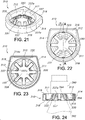
FIG. 21 is a top, perspective view of a tag housing assembly not encompassed by the present invention. -
FIGs. 22 and 23 show, respectively, top and bottom plan views of the tag housing assembly shown inFIG. 21 . -
FIG. 24 is a sectional view of the tag housing assembly taken at line A-A shown inFIG. 22 attached to a bottle. -
FIG. 25 is an exploded, perspective view of a tag housing assembly not encompassed by the present invention. -
FIG. 26 is a top, perspective view of the tag housing assembly shown inFIG. 25 . -
FIG. 27 is a bottom, perspective view of the tag housing assembly shown inFIG. 25 . -
FIG. 28 is a bottom, perspective view of the top housing portion of the tag housing assembly shown inFIG. 25 . -
FIG. 29 is a top, perspective view of the bottom housing portion of the tag housing assembly shown inFIG. 25 . -
FIG. 30 is an exploded, perspective view of a tag housing assembly not encompassed by the present invention with a snap on cover for enclosing a security device. -
FIG. 31 is a top, perspective view of the tag housing assembly shown inFIG. 30 with the cover for the security device in the closed position. -
FIG. 32 is a side view of the tag housing assembly shown inFIG. 31 secured to a bottle. -
FIG. 33 is a bottom view of the tag housing assembly shown inFIG. 31 . -
FIG. 34 is an exploded, perspective view of the tag housing assembly ofFIG. 30 with an attachable cover for enclosing a security device. -
FIG. 35 is a top, perspective view of the tag housing assembly shown inFIG. 34 with the cover for the security device in the closed position. -
FIG. 36 is a side view of the tag housing assembly shown inFIG. 35 attached to a bottle. -
FIG. 37 is a bottom view of the tag housing assembly shown inFIG. 35 . -
FIG. 38 is a top, perspective view of a two-piece detachable tag housing assembly not encompassed by the present invention in the open position. -
FIG. 39 is a top, perspective view of the tag housing assembly shown inFIG. 38 in the closed position. -
FIG. 40 is a bottom, perspective view of the tag housing assembly shown inFIG. 38 in the closed position. -
FIG. 41 is a top, perspective view of the tag housing assembly shown inFIG. 38 in the closed position and with a flat, interior wall. -
FIG. 42 is a side view of the tag housing assembly shown inFIG. 38 in the closed position attached to a bottle. -
FIG. 43 is an exploded, perspective view of the first housing of the tag housing assembly shown inFIG. 38 . -
FIG. 44 is a perspective view of the second housing of the tag housing assembly shown inFIG. 38 . -
FIG. 45 is a bottom, perspective view of the first housing of the tag housing assembly shown inFIG. 38 . -
FIG. 46 is a bottom view of the second housing of the tag housing assembly shown inFIG. 38 . -
FIG. 47 is a perspective, top view of a pivotable tag housing assembly encompassed by the present invention in the open position. -
FIG. 48 is a top view of the pivotable tag housing assembly shown inFIG. 47 . -
FIG. 49 is a side view of the pivotable tag housing assembly shown inFIG. 47 attached to a bottle. -
FIG. 50 is a bottom view of the pivotable tag housing assembly shown inFIG. 47 . -
FIG. 51 is a top, perspective view of the pivotable tag housing assembly shown inFIG. 47 in the closed position. -
FIG. 52 is a perspective view of a pivotal tag housing assembly positioned around the neck of a bottle in the open position. -
FIG. 53 is a perspective view of a pivotal tag housing assembly positioned around the neck of a bottle in the closed position. -
FIG. 54 is a detail, side view of the pivotal tag housing assembly shown inFIG. 53 . -
FIG. 55 is a top view of the pivotal tag housing assembly shown inFIG. 53 . -
FIG. 56 is side view of the pivotal tag housing assembly shown inFIG. 53 . - The embodiments which are not part of the invention however show some of its optional features.
- The present invention provides a tag housing assembly for attaching at least one electronic tag to an extending neck of a bottle that can have a perimetrical undercut thereabout.
- The housing assembly includes a first housing capable of supporting at least one electronic tag and a second housing capable of supporting at least one electronic tag. The first and second housings are detachably coupled to define a substantially round or oval opening therebetween for receiving the extending neck of the bottle. Each of the first and second housings includes one or more retaining devices disposed about the opening, which define therebetween an adjustable aperture for accommodating the neck of the bottle therethrough. The first and second housings are movable to an attached, clamped position about the bottle neck and subsequently movable to a detached, unclamped position to permit removal of the first and second housings from about the bottle. A removal tool can be used to detach the first housing from the second housing.
- The housing assembly includes a first housing capable of supporting at least one electronic tag and a second housing capable of supporting at least one electronic tag. The first and second housings each have a top and bottom surface connected by an interior side wall and an exterior side wall. The first and second housings are adjustably and detachably coupled to define a substantially round or oval adjustable opening therebetween for receiving the extending neck of the bottle. The first housing has a pair of passages for adjustably receiving a pair of arms that extend from the second housing on either side of the opening. The first and second housings are movable to one or more attached, clamped positions about the bottle neck, which accommodates different size bottle necks, and subsequently movable to a detached, unclamped position to permit removal of the bottle from the opening.
- In an embodiment, the housing assembly includes a first housing capable of supporting at least one electronic tag and a second housing capable of supporting at least one electronic tag. The first and second housings each have a top surface, an exterior side wall and an interior side wall. The first and second housings are pivotally connected on one side and attachably coupled on the opposing side so that the two housings pivot in a plane that is parallel to the top surface. When the first and second housings are coupled, the interior side walls define a substantially round or oval opening therebetween for receiving the extending neck of the bottle. A flexible retaining device extends around the opening and defines an adjustable aperture for accommodation around the neck of a bottle. The flexible retaining device is formed by a plurality of flexible fingers, which engage the perimetrical undercut of the bottle neck with their distal ends. The first and second housings are movable to an attached, coupled or clamped position about the bottle neck and subsequently movable to a detached, unclamped position to permit removal of the bottle from the opening.
- The tag housing assembly and the different embodiments will now be described with respect to the drawings. A
tag housing assembly 110 is shown inFIGs. 1-4 . Thetag housing assembly 110 includes anupper housing portion 112, also shown inFIG. 5 ; alower housing portion 114, also shown inFIG. 7 ; and amovable retaining device 116, also shown inFIG. 6 . Theupper housing portion 112 is formed by atop surface 111 and aperimetrical side wall 113 extending downwardly from the edges. Thelower housing portion 114 includes abase plate 119. When assembled as shown inFIGs. 2, 3 and 4 , thehousing assembly 110 supports one or more electronic tags, such as anEAS tag 115 and/or aRFID tag 117, in an interior thereof. Theupper housing portion 112 is joined with thelower housing portion 114 and can be secured thereto using a variety of securement techniques, preferably ultrasonic welding around the peripheral rim thereof. - The upper and
lower housing portions central opening 120 therethrough for accommodation over the extendingneck 190 of abottle 192 with a perimetrical indent 194 (FIG. 3 ). Thelower housing portion 114 includes a fixedretaining device 122 in the form of a plurality of spaced apartflexible fingers 124 extending approximately half way about theopening 120. Thelower housing portion 114 also supports amovable retaining device 116 in the interior ofhousing assembly 110. Themovable retaining device 116 also includes a plurality of spaced apartflexible fingers 126 extending half way about theopening 120. Together theflexible fingers movable retaining devices adjustable aperture 128 for surrounding accommodation of theneck 190 of thebottle 192 extending throughopening 120. - The movable retaining device as shown in
FIG. 6 includes a pair ofwings slots bottom housing portion 114 and moved to a forward position,tabs recesses lower housing portion 114. When seated inlower housing portion 114, themovable retaining device 116 is adjusted so as to move forward towards the fixedretaining device 122 as shown inFIG. 4 whereupon themovable retaining device 116 is placed in a clamping position with the fixedretaining device 122 to clamp thehousing assembly 110 to theneck 190 ofbottle 192 beneath undercut 194. Thus, in the clamping position, thehousing assembly 110 is fixedly coupled to theneck 190 of thebottle 192. - In order to remove the housing from its clamped position with the
neck 190 of thebottle 192, a removal tool is employed. Theremoval tool 160 is shown inFIGs. 8-12 . Theremoval tool 160 includes anupper portion 162 and alower portion 164, which are ultrasonically or similarly coupled together. Thelower portion 164 includes a pair of spaced apart rails 166 and 168. Upon placing theremoval tool 160 into engagement with thehousing assembly 110, therails slots base plate 119 of the lower housing portion 114 (FIGs. 1, 3 ). Each of therails portion tabs movable retaining device 116 and lift thewings recesses portions tabs handle 165 on theremoval tool 160 is used to pull backward (in the direction of arrow A-FIG. 12 )) so that it moves back inslots device 116, expandingopening 128 and movingfingers 126 away from clamping engagement with thebottle neck 190. Once this is achieved, theremoval tool 160 can be removed from thehousing assembly 110 and thehousing assembly 110 may be lifted from thebottle neck 190 removing thehousing assembly 110 therefrom. - It is contemplated that such a
removal tool 160 would be employed at the point of purchase such as a checkout counter after thetag housing 110 attached to thebottle 192 is been scanned at the check-out counter and the information contained on theRFID 117 and/orEAS tags 115 is retrieved and/or the alarm is deactivated. - A
tag housing assembly 210 of the present invention is shown inFIGs. 13 and15-18 . Thetag assembly 210 includes afirst housing 212 and asecond housing 214, which are detachably coupled together to define therebetween anopening 220 for receiving the extendingneck 290 of abottle 292 with a perimetrical undercut 294. - As more clearly illustrated in
FIG. 17 , thefirst housing 212 includes anupper portion 224 and alower portion 226. Theupper portion 212 includes atop surface 211 with aperimetrical side wall 213 extending downwardly from the outer edges. Thelower portion 214 includes abase plate 219. Thefirst housing 212 is designed to accommodate therebetween an electronic tag such as anRFID tag 217. Theupper portion 224 is coupled to thelower portion 226 by ultrasonic welding or similar attachment techniques. Thelower portion 226, as shown inFIG. 17 , includes afirst retaining device 230 which includes a plurality of upwardly extending spaced apartfingers 232. Thefingers 232 extend approximately half way about theopening 220 as shown inFIG. 13 . -
FIG. 18 shows thesecond housing 214 including anupper portion 234 and alower portion 236. Thehousing portions EAS tag 215. Thelower portion 236 includes abase plate 239 and aretaining device 238 having a plurality of upwardly extendingflexible fingers 239, which also extends half way about opening 220. Together theflexible fingers devices FIG. 13 ) for surrounding accommodation of theneck 290 of thebottle 292. - Referring again to
FIG. 13 , thefirst housing 212 includes a pair of extendingarms 250, which are designed to be inserted intopassages second housing 214. Eacharm 250 includes a pair of elongate upper and lower spring latches 260, 262, which are deflectable to lockingly couple thefirst housing 212 to thesecond housing 214 at one or more locations, as shown in further detail with respect to the description ofFIG. 20 hereinbelow. Thearms 250 also include a stiffeningmember 266 having a tapered lead-in 266a to help insert and support thefirst housing 212 andsecond housing 214 and prevent inadvertent separation of the twohousings - The two
housings FIGs. 15 and 16 . In the clamping position, thehousing assembly 210 can be fixedly coupled to theneck 290 of abottle 292, such as the one shown inFIG. 14 . Thefingers neck 290 below the undercut 294 on thebottle 292 and thetag housing assembly 210 can only be removed using theremoval tool 280. - As shown in
FIG. 20 , the distal ends of thearms 250 are received in thepassages second housing 214 and secured in the clamping position by the spring latches 260, 262. Thepassages material tag housing assembly 210 from thebottle 292. - The
removal tool 280 is shown inFIGs. 19 and 20 . Theremoval tool 280 includes ahousing body 281 which supports therein a pair of jaw-like upper andlower finger elements like finger elements spring 286 that provides spring-opposed actuation. When in a closed position, thedistal tips thin material passages FIG. 13 ). This deflects the spring latches 260, 262 inwardly towards one another releasing them from their latched position and thereby allowing thearms 250 to be withdrawn from thepassages first housing 212 is separated from thesecond housing 214. As the removal tool is pulled back (in the direction of arrow A), thesecond housing 214 is pulled away from thefirst housing 212 to expandaperture 228 and permit removal of thehousing assembly 210 from thebottle neck 290. - Another
tag housing assembly 310 is shown inFIGs. 21-24 .Tag housing assembly 310 includes a one-piece integrally formedhousing 311, which as particularly shown inFIG. 23 includes a perimetricalinner housing wall 312 and a perimetricalouter housing wall 314. Aplanar surface 316 extends between the inner and outerperimetrical walls planar surface 316, the innerperimetrical wall 312 and outerperimetrical wall 314 define an open endedcavity 318, which accommodates anelectronic tag 315. Thetag 315 may include an EAS or RFID tag, or any similar electronic tag commonly used for such purpose. The innerperimetrical wall 312 defines anopening 320 for insertable accommodation of theneck 390 of a bottle 392 (FIG. 24 ). -
FIG. 23 shows thetag 315 adhesively secured to aninside surface 314a of the outerperimetrical wall 314. Other securement techniques may also be employed. As shown in theFIGs. 22 and 23 , one side of outerperimetrical wall 314 may be planar to accommodate securement of thetag 315. - The retaining
device 330 is integrally formed with and extend inwardly from the innerperimetrical wall 312. The retainingdevice 330 has a plurality of inwardly directed, resilientlydeflectable fingers 332, which are circumferentially spaced apart. Thefingers 332 of the retainingdevice 330 extend into theopening 320 defined by innerperimetrical wall 312 and define anadjustable aperture 328 for receipt of theneck 390 ofbottle 392. Theaperture 328 defined byfingers 332 is smaller than theneck 390 of thebottle 392 so that upon insertion of theneck 390 of thebottle 392 into theopening 320 in thetag housing assembly 310, thefingers 332 deflect outwardly to permit passage of thebottle neck 390. Thefingers 332 are cantilevered from the base of theinner wall 312 ad extend upwardly therefrom. Thefingers 332 are deflectable outwardly to allow the insertion of thebottle neck 390. The deflectedfingers 332 tightly grip thebottle neck 390. - Each of the fingers has a
distal extent 337 defining an inwardly directedlip 337a, which is seatable against the undercut 394 of theneck 390 of thebottle 392. The construction and arrangement of thefingers 332 permit the fingers to resiliently engage theneck 390 of thebottle 392 and such that thelip 337a non-releasably seats within the undercut 394 of thebottle 392. Once seated in the undercut 394, thetag housing assembly 310 cannot be removed from thebottle neck 390 by sliding it therealong. Such arrangement non-releasably attaches thetag housing assembly 310 to theneck 390 of thebottle 392, preventing non-destructible removal therefrom. - Another tag housing is shown in
FIGs. 25-37 . Thetag housing assembly 410 includes anupper housing portion 412 and alower housing portion 414 that are joined together to define an interior therebetween. Theupper housing portion 412 has atop surface 411 with aperimetrical side wall 413 extending downwardly from thetop surface 411. Thelower housing portion 414 has abase 419. A substantially round oroval opening 420 extends from thetop surface 411 of theupper housing portion 412 through thebase 419 of thelower housing portion 414 for receiving theneck 490 of a bottle 492 (seeFIG. 32 ). The housing interior can accommodate anEAS tag 415 and/or aRFID tag 417. Thelower housing portion 414 has aflexible retaining device 430 extending around theopening 420, which defines anadjustable aperture 428 for accommodation around theneck 490 of abottle 492. Theflexible retaining device 430 is formed by a plurality offlexible fingers 432. Theneck 490 of thebottle 492 is inserted into theopening 420 and theflexible fingers 432 engage the perimetrical undercut 494 of thebottle neck 490 with their distal ends 437. - One end of the
upper housing portion 412 can extend upwardly from thetop surface 411 to form anelongated housing portion 416 with acavity 418 sized for receiving theEAS tag 415 or aRFID tag 417. Thetag cavity 418 and then thelower housing portion 414 is attached to theupper housing portion 412 using an adhesive or ultrasonic welding. Once the tags are secured inside thetag housing assembly 410, the housing has to be fractured in order to remove the tag(s).FIGs. 30, 31, 33 and34, 35, 37 show embodiments wherein theelongated housing portion 416 extends upwardly from the end of theupper housing portion 412. After theEAS tag 415 or aRFID tag 417 is inserted in theelongated housing portion 416, a cover is placed over theelongated housing portion 416 and secured in place using an adhesive or ultrasonic welding. - Another tag housing assembly is shown in
FIGs. 38-46 . Thehousing assembly 510 includes afirst housing 512 and asecond housing 514 capable of supporting an EAS tag 515 and/or aRFID tag 517. The first andsecond housings top surface bottom surface interior side wall exterior side wall second housings adjustable opening 520 therebetween for receiving the extending neck of the bottle (FIG. 42 ). The first andsecond housings more ribs interior side walls top surfaces base plates neck 590 of thebottle 592 therebetween. As shown inFIG. 41 , theinterior side walls second housings bottle neck 590 and subsequently movable to a detached, unclamped position to permit removal of thebottle 592 from theopening 520. - As shown in
FIGs. 38 ,43 and 44 , a pair ofarms second housing 514 and are adjustably inserted in a pair ofpassages first housing 512. Eacharm latch recess top surface 511a of thefirst housing 512. When thetag housing assembly 510 is attached to a bottle 592 (FIG. 42 ), thearms passages latches recesses second housings tag housing assembly 510 can be removed using a tool similar to the one shown inFIGs. 19 and 20 .FIGs. 40 and43 show a pair offlexible members base plate 519a of thefirst housing 512. As shown inFIG. 43 , thesemembers passages first housing 512 and have tapered distal ends 559, 561. To remove thetag housing assembly 510 from theneck 590 of abottle 592, the tool presses inwardly on the tworecesses first housing 512 and on theflexible members arms passages housings - As shown in
FIG. 43 , one end of theupper housing portion 512 can extend upwardly from thetop surface 511a to form anelongated housing portion 516 with acavity 518 sized for receiving aRFID tag 517. Thetag 517 is inserted in to thecavity 518 and then thebase plate 519a is attached to theupper housing portion 512 using an adhesive or ultrasonic welding. - The
tag housing assembly 610 shown inFIGs. 47-56 includes afirst housing 612 and asecond housing 614 capable of supporting at least one electronic tag, preferably anEAS tag 615 and/or aRFID tag 617.FIGs. 47, 48, 50 and 51 show thetag housing 610 andFIGs. 49 and52-56 show thetag housing 610 attached to abottle 692. The first andsecond housings top surface exterior side wall interior side wall 625a, 625b. The first andsecond housings hinge 616, and attachably coupled on the opposing side so that the twohousings top surfaces second housings interior side walls 625a, 625b define a substantially round oroval opening 620 therebetween for receiving the extendingneck 690 of thebottle 692. Aflexible retaining device 630 extends around theopening 620 and defines anadjustable aperture 628 for accommodation around thebottle neck 690. Preferably, theflexible retaining device 630 is formed by a plurality offlexible fingers 632, which engage the perimetrical undercut 694 of thebottle neck 690 with their distal ends 637. The first andsecond housings bottle neck 690 and subsequently movable to a detached, unclamped position to permit removal of thebottle 690 from thetag housing assembly 610. - The
exterior walls tag housing assembly 610 are substantially rectangular in shape and the first andsecond housings hinge 626 located at one corner and releasably connected by a locking mechanism located at the opposing corner. Preferably, the locking mechanism includes afirst locking aperture 650 in thefirst housing 612 and asecond locking aperture 652 in thesecond housing 614. After thetag housing assembly 610 is attached to theneck 690 of abottle 692, the first andsecond locking apertures locking pin 654 is inserted therethrough to secure the twohousings locking pin 654 can be permanently secured in the lockingapertures locking pin 654. - One end of the
upper housing portion 612 can extend upwardly from thetop surface 611a to form anelongated housing portion 616 with acavity 618 sized for receiving theEAS tag 615 or aRFID tag 617. Thetag cavity 618 and then thebase 619 of thefirst housing 612 is attached using an adhesive or ultrasonic welding. Once the tags are secured inside thetag housing assembly 610, the housing has to be fractured in order to remove the tag(s).
Claims (13)
- A tag housing assembly (210) for attaching an electronic tag (215) to an extending neck (290) of a bottle (292), wherein the neck has a perimetrical undercut (294) thereabout, the tag housing assembly comprising:a tag housing comprising a perimetrical exterior side wall (213) extending between a top surface (211) and a base plate (219) to define an interior and an opening (220) extending through the top surface and the base plate for receiving the extending neck of the bottle;at least one electronic tag (217) located in the interior; anda retaining device (230) extending into the opening and defining an adjustable aperture (228) for engaging the extending neck of the bottle;characterised in that, when the tag housing is in a closed position, the retaining device is secured to the neck of the bottle, wherein the tag housing comprises a first housing (212) and a second housing (214), wherein the first and second housings are detachably connected together to define therebetween the opening (220) for receiving the extending neck (290) of the bottle (292) with a perimetrical undercut (294), wherein the retaining device (230,238) comprises a first section (226) and a second section (236) wherein the first and second sections of the retaining device comprise a plurality of flexible fingers (232,239), wherein each flexible finger extends from the base plate to a distal end for surrounding engagement with the perimetrical undercut (294) of the neck of the bottle.
- The tag housing assembly according to claim 1, wherein the flexible fingers (232, 632; 239, 639) extend upwardly from the base plate.
- The tag housing assembly according to claim 2, wherein the retaining device (230) is fixedly attached to the base plate and the size of the adjustable aperture (228) increases to receive a bottle neck, and wherein, after the perimetrical undercut (294) passes through the adjustable aperture, the distal ends of the fingers (232, 239) engage the bottle neck and prevent the tag housing assembly from being removed from the bottle.
- The tag housing assembly according to claim 1, wherein the first and second housings (212,214) are pivotably connected by a hinge (626) on one side of the tag housing and locked together by a latching mechanism on the opposite side.
- The tag housing assembly according to claim 1, wherein the exterior side wall (213) has a first end and a second end and first and second substantially parallel sides extending therebetween, and wherein the first housing (212) comprises the first end and the first side and the second housing (214) comprises the second end and the second side.
- The tag housing assembly according to claim 1, wherein the first housing (212) comprises a pair of arms (250) and the second housing (214) comprises a pair of passages (254,256) for receiving the arms, and wherein each of the pair of the arms has a latch (260,262) for securing the arms in the passages.
- The tag housing assembly according to claim 6, wherein each arm (250) includes a pair of elongate upper and lower spring latches (260, 262), which are deflectable to lockingly couple the first housing (212) to the second housing (214) at one or more locations
- The tag housing assembly according to claim 1, wherein the first section of the retaining device is fixedly attached to the base plate and the second section is movably attached to the base plate, and wherein the movement of the second section changes the size of the adjustable aperture.
- The tag housing of claim 1, wherein the tag housing further comprises a locking mechanism (650,652) for locking the movable second section of the retaining device in a fixed position.
- The tag housing of claim 1, wherein the second section of the retaining device is movable within the housing interior upon application of a removal tool (280).
- The tag housing assembly according to claim 4, wherein the first housing comprises a first latching element and the second housing comprises a second latching element opposite the hinge.
- The tag housing assembly according to claim 11, wherein the first and second latching elements are first and second latching apertures, respectively, and wherein, when the tag housing is in the closed position, the first and second latching apertures are aligned.
- The tag housing assembly according to claim 12, wherein the tag housing further comprises a latching pin, wherein the latching pin is inserted in the first and second latching apertures to lock the tag housing.
Priority Applications (1)
| Application Number | Priority Date | Filing Date | Title |
|---|---|---|---|
| EP19157778.2A EP3518199B1 (en) | 2013-02-27 | 2014-02-27 | Tag housing assembly for attachment to a bottle neck |
Applications Claiming Priority (4)
| Application Number | Priority Date | Filing Date | Title |
|---|---|---|---|
| US201361769926P | 2013-02-27 | 2013-02-27 | |
| US201361769917P | 2013-02-27 | 2013-02-27 | |
| US201361819012P | 2013-05-03 | 2013-05-03 | |
| PCT/US2014/018986 WO2014134292A1 (en) | 2013-02-27 | 2014-02-27 | Tag housing assembly for attachment to a bottle neck |
Related Child Applications (1)
| Application Number | Title | Priority Date | Filing Date |
|---|---|---|---|
| EP19157778.2A Division EP3518199B1 (en) | 2013-02-27 | 2014-02-27 | Tag housing assembly for attachment to a bottle neck |
Publications (3)
| Publication Number | Publication Date |
|---|---|
| EP2962288A1 EP2962288A1 (en) | 2016-01-06 |
| EP2962288A4 EP2962288A4 (en) | 2016-09-28 |
| EP2962288B1 true EP2962288B1 (en) | 2019-02-20 |
Family
ID=51428800
Family Applications (2)
| Application Number | Title | Priority Date | Filing Date |
|---|---|---|---|
| EP14757059.2A Active EP2962288B1 (en) | 2013-02-27 | 2014-02-27 | Tag housing assembly for attachment to a bottle neck |
| EP19157778.2A Active EP3518199B1 (en) | 2013-02-27 | 2014-02-27 | Tag housing assembly for attachment to a bottle neck |
Family Applications After (1)
| Application Number | Title | Priority Date | Filing Date |
|---|---|---|---|
| EP19157778.2A Active EP3518199B1 (en) | 2013-02-27 | 2014-02-27 | Tag housing assembly for attachment to a bottle neck |
Country Status (5)
| Country | Link |
|---|---|
| US (1) | US9607259B2 (en) |
| EP (2) | EP2962288B1 (en) |
| BR (1) | BR112015020732B1 (en) |
| MX (1) | MX365199B (en) |
| WO (1) | WO2014134292A1 (en) |
Families Citing this family (13)
| Publication number | Priority date | Publication date | Assignee | Title |
|---|---|---|---|---|
| US9576453B2 (en) * | 2013-10-21 | 2017-02-21 | B&G Plastics, Inc. | Consumer removable tag housing assembly for attachment to a bottle neck |
| US20170175426A1 (en) * | 2015-12-18 | 2017-06-22 | Checkpoint Systems, Inc. | Anti-impact locking feature |
| JP6929301B2 (en) | 2016-04-25 | 2021-09-01 | インテグラ ライフサイエンシーズ エンタープライジーズ, エルエルエルピー | Liquid transfer tube for ultrasonic suction surgical horn |
| USD820441S1 (en) | 2016-06-13 | 2018-06-12 | Integra Lifesciences Nr Ireland Limited | Surgical handpiece nosecone |
| US12109352B2 (en) | 2016-05-20 | 2024-10-08 | Integra Lifesciences Enterprises, Lllp | Ergonomic tubing attachment for medical apparatus |
| EP3463125B1 (en) * | 2016-05-24 | 2022-08-31 | Integra LifeSciences Enterprises, LLLP | Ergonomic tubing attachment for medical apparatus |
| ES2846351T3 (en) | 2016-11-16 | 2021-07-28 | Integra Lifesciences Entpr Lllp | Ultrasonic Surgical Handpiece |
| US10687840B1 (en) | 2016-11-17 | 2020-06-23 | Integra Lifesciences Nr Ireland Limited | Ultrasonic transducer tissue selectivity |
| WO2019040643A1 (en) * | 2017-08-23 | 2019-02-28 | Midwest Innovative Products, Llc | Electronic device for attachment to a beverage container |
| US10748051B2 (en) * | 2018-06-29 | 2020-08-18 | Intelligent Design Systems Inc. | System and method for attaching identification tags to objects using a flexible attachment device |
| USD1008834S1 (en) * | 2020-01-07 | 2023-12-26 | Carrier Corporation | Snap-on item tracking device |
| DE102020211267A1 (en) | 2020-09-08 | 2022-03-10 | Rapitag Gmbh | locking device |
| US12374201B2 (en) * | 2022-09-01 | 2025-07-29 | Edge Security Products, Llc | Adjustable curved surface security device |
Family Cites Families (25)
| Publication number | Priority date | Publication date | Assignee | Title |
|---|---|---|---|---|
| BR9911550A (en) | 1998-06-24 | 2001-05-08 | Alpha Entpr Inc | Bottle safety device for use with a bottle having a neck |
| US6696955B2 (en) | 2002-03-05 | 2004-02-24 | B&G Plastics, Inc. | Electronic article surveillance marker and container therewith |
| US6912878B2 (en) | 2003-02-24 | 2005-07-05 | Alpha Security Products, Inc. | Bottle security device |
| US7227467B2 (en) * | 2003-10-29 | 2007-06-05 | Display Technologies, Inc. | Anti-theft tag |
| BRPI0518369A2 (en) * | 2004-12-07 | 2008-11-18 | Sensormatic Electronics Corp | safety device having a cable |
| US8264350B2 (en) * | 2004-12-07 | 2012-09-11 | Sensormatic Electronics, LLC | Adjustable constraining adaptive insert for merchandise security tag and method thereof |
| US7259674B2 (en) | 2004-12-22 | 2007-08-21 | Alpha Security Products, Inc. | Bottle security device |
| US7262699B2 (en) | 2004-12-30 | 2007-08-28 | Alpha Security Products, Inc. | Security device for cylindrical merchandise |
| ES2328735T3 (en) * | 2005-05-20 | 2009-11-17 | Premier Security Products Limited | BOTTLE PLUG PROTECTOR. |
| US7804405B2 (en) | 2005-09-09 | 2010-09-28 | B&G International, Inc. | Tamper-evident bottle overcap for supporting an electronic tag |
| US7394376B1 (en) * | 2005-10-19 | 2008-07-01 | Sayegh Adel O | Theft deterrent tag |
| US7650768B2 (en) * | 2006-01-13 | 2010-01-26 | Checkpoint Systems, Inc. | Bottle security device |
| US7583195B2 (en) | 2006-08-22 | 2009-09-01 | Checkpoint Systems, Inc. | Security tag adapter for containers |
| US7866497B2 (en) * | 2007-12-12 | 2011-01-11 | Checkpoint Systems, Inc. | Bottle security device |
| US8269631B2 (en) * | 2008-02-22 | 2012-09-18 | Xiao Hui Yang | Anti-theft device |
| US8466793B2 (en) | 2008-10-03 | 2013-06-18 | B&G Plastics, Inc. | Electronic tag holder for bottle neck |
| US8228200B2 (en) | 2008-10-03 | 2012-07-24 | B&G Plastics, Inc. | Electronic tag holder for bottle neck |
| US9396670B2 (en) | 2008-12-03 | 2016-07-19 | B&G International, Inc. | Electronic tag holder for capped bottle neck |
| US8432286B2 (en) | 2008-12-03 | 2013-04-30 | B&G International, Inc. | Electronic tag holder for capped bottle neck |
| US8294583B2 (en) * | 2009-02-27 | 2012-10-23 | Universal Surveillance Corporation | Theft deterrent tag |
| US8525675B2 (en) * | 2010-03-12 | 2013-09-03 | Checkpoint Systems, Inc. | Security device |
| US9311797B2 (en) * | 2010-04-05 | 2016-04-12 | Wg Security Products | EAS tag for bottles |
| US8267326B2 (en) * | 2010-07-09 | 2012-09-18 | B&G Plastics, Inc. | Tag for bottle neck having integral locking ring |
| US8730046B2 (en) | 2010-10-01 | 2014-05-20 | B&G Plastics, Inc. | EAS integrated faucet tag assembly |
| CN201873118U (en) * | 2010-12-07 | 2011-06-22 | 施建孟 | Antitheft wine bottle label |
-
2014
- 2014-02-27 EP EP14757059.2A patent/EP2962288B1/en active Active
- 2014-02-27 EP EP19157778.2A patent/EP3518199B1/en active Active
- 2014-02-27 WO PCT/US2014/018986 patent/WO2014134292A1/en not_active Ceased
- 2014-02-27 MX MX2015011033A patent/MX365199B/en active IP Right Grant
- 2014-02-27 US US14/768,957 patent/US9607259B2/en active Active
- 2014-02-27 BR BR112015020732-4A patent/BR112015020732B1/en active IP Right Grant
Non-Patent Citations (1)
| Title |
|---|
| None * |
Also Published As
| Publication number | Publication date |
|---|---|
| MX365199B (en) | 2019-05-27 |
| MX2015011033A (en) | 2016-06-14 |
| EP3518199A1 (en) | 2019-07-31 |
| EP2962288A4 (en) | 2016-09-28 |
| EP2962288A1 (en) | 2016-01-06 |
| BR112015020732A2 (en) | 2017-12-19 |
| WO2014134292A1 (en) | 2014-09-04 |
| EP3518199B1 (en) | 2021-01-20 |
| US9607259B2 (en) | 2017-03-28 |
| BR112015020732B1 (en) | 2022-01-25 |
| US20160004951A1 (en) | 2016-01-07 |
Similar Documents
| Publication | Publication Date | Title |
|---|---|---|
| EP2962288B1 (en) | Tag housing assembly for attachment to a bottle neck | |
| US7464569B2 (en) | Zipper tag housing | |
| US10577165B2 (en) | Key retention system for product packaging | |
| US9576453B2 (en) | Consumer removable tag housing assembly for attachment to a bottle neck | |
| NL2008358C2 (en) | Safety hammer, holder for a safety hammer, system of a safety hammer and holder, method for assembly of a safety hammer. | |
| US7207088B2 (en) | Door hook with removable spacer | |
| US8432286B2 (en) | Electronic tag holder for capped bottle neck | |
| EP2590865B1 (en) | Tag for bottle neck having integral locking ring | |
| CN104773380A (en) | Caps for supporting transponders on bottle caps | |
| US20150290819A1 (en) | Shaver | |
| US8466793B2 (en) | Electronic tag holder for bottle neck | |
| EP3466466A2 (en) | Pen needle packaging | |
| MX2010010755A (en) | Electronic tag housing having cable tie support. | |
| US20150267439A1 (en) | Removable attachment device for attaching to longer linear or filiform objects | |
| US20150206461A1 (en) | Battery cassette and an electronic shelf label comprising said battery cassette | |
| US20050018931A1 (en) | Method and apparatus for hanging a resealable bag | |
| US10638763B2 (en) | Bread lame | |
| US5772059A (en) | Closure for sharps disposal container having temporary and permanent closed positions | |
| EP1753667B1 (en) | Gripping device for use on a paint receptacle, in particular a tin of paint | |
| JP2002262921A (en) | Fitting device for fitting portable article | |
| US4027386A (en) | Cutting implement | |
| US20110309648A1 (en) | Article to fix on a support provided with an opening and assist grip handle compromising it | |
| US20080125810A1 (en) | Encased tweezers | |
| CN106458405B (en) | Hanging Label Packages for Saw Blades | |
| US20100000996A1 (en) | Closure of vessel and process for manufacturing same |
Legal Events
| Date | Code | Title | Description |
|---|---|---|---|
| PUAI | Public reference made under article 153(3) epc to a published international application that has entered the european phase |
Free format text: ORIGINAL CODE: 0009012 |
|
| 17P | Request for examination filed |
Effective date: 20150915 |
|
| AK | Designated contracting states |
Kind code of ref document: A1 Designated state(s): AL AT BE BG CH CY CZ DE DK EE ES FI FR GB GR HR HU IE IS IT LI LT LU LV MC MK MT NL NO PL PT RO RS SE SI SK SM TR |
|
| AX | Request for extension of the european patent |
Extension state: BA ME |
|
| RAP1 | Party data changed (applicant data changed or rights of an application transferred) |
Owner name: B&G PLASTICS, INC. |
|
| RIN1 | Information on inventor provided before grant (corrected) |
Inventor name: NORMAN, MICHAEL Inventor name: TETIYEVSKY, ALEX Inventor name: CUNNEEN, DANIEL Inventor name: STRASSBURGER, JACOB |
|
| DAX | Request for extension of the european patent (deleted) | ||
| A4 | Supplementary search report drawn up and despatched |
Effective date: 20160829 |
|
| RIC1 | Information provided on ipc code assigned before grant |
Ipc: G08B 23/00 20060101AFI20160823BHEP |
|
| GRAP | Despatch of communication of intention to grant a patent |
Free format text: ORIGINAL CODE: EPIDOSNIGR1 |
|
| STAA | Information on the status of an ep patent application or granted ep patent |
Free format text: STATUS: GRANT OF PATENT IS INTENDED |
|
| INTG | Intention to grant announced |
Effective date: 20170823 |
|
| GRAJ | Information related to disapproval of communication of intention to grant by the applicant or resumption of examination proceedings by the epo deleted |
Free format text: ORIGINAL CODE: EPIDOSDIGR1 |
|
| STAA | Information on the status of an ep patent application or granted ep patent |
Free format text: STATUS: REQUEST FOR EXAMINATION WAS MADE |
|
| STAA | Information on the status of an ep patent application or granted ep patent |
Free format text: STATUS: EXAMINATION IS IN PROGRESS |
|
| 17Q | First examination report despatched |
Effective date: 20180103 |
|
| INTC | Intention to grant announced (deleted) | ||
| RAP1 | Party data changed (applicant data changed or rights of an application transferred) |
Owner name: B&G PLASTICS, INC. |
|
| GRAS | Grant fee paid |
Free format text: ORIGINAL CODE: EPIDOSNIGR3 |
|
| STAA | Information on the status of an ep patent application or granted ep patent |
Free format text: STATUS: GRANT OF PATENT IS INTENDED |
|
| GRAP | Despatch of communication of intention to grant a patent |
Free format text: ORIGINAL CODE: EPIDOSNIGR1 |
|
| INTG | Intention to grant announced |
Effective date: 20180912 |
|
| GRAA | (expected) grant |
Free format text: ORIGINAL CODE: 0009210 |
|
| STAA | Information on the status of an ep patent application or granted ep patent |
Free format text: STATUS: THE PATENT HAS BEEN GRANTED |
|
| AK | Designated contracting states |
Kind code of ref document: B1 Designated state(s): AL AT BE BG CH CY CZ DE DK EE ES FI FR GB GR HR HU IE IS IT LI LT LU LV MC MK MT NL NO PL PT RO RS SE SI SK SM TR |
|
| REG | Reference to a national code |
Ref country code: GB Ref legal event code: FG4D |
|
| REG | Reference to a national code |
Ref country code: CH Ref legal event code: EP |
|
| REG | Reference to a national code |
Ref country code: DE Ref legal event code: R096 Ref document number: 602014041294 Country of ref document: DE |
|
| REG | Reference to a national code |
Ref country code: AT Ref legal event code: REF Ref document number: 1099223 Country of ref document: AT Kind code of ref document: T Effective date: 20190315 |
|
| REG | Reference to a national code |
Ref country code: IE Ref legal event code: FG4D |
|
| REG | Reference to a national code |
Ref country code: NL Ref legal event code: MP Effective date: 20190220 |
|
| REG | Reference to a national code |
Ref country code: LT Ref legal event code: MG4D |
|
| PG25 | Lapsed in a contracting state [announced via postgrant information from national office to epo] |
Ref country code: NO Free format text: LAPSE BECAUSE OF FAILURE TO SUBMIT A TRANSLATION OF THE DESCRIPTION OR TO PAY THE FEE WITHIN THE PRESCRIBED TIME-LIMIT Effective date: 20190520 Ref country code: NL Free format text: LAPSE BECAUSE OF FAILURE TO SUBMIT A TRANSLATION OF THE DESCRIPTION OR TO PAY THE FEE WITHIN THE PRESCRIBED TIME-LIMIT Effective date: 20190220 Ref country code: LT Free format text: LAPSE BECAUSE OF FAILURE TO SUBMIT A TRANSLATION OF THE DESCRIPTION OR TO PAY THE FEE WITHIN THE PRESCRIBED TIME-LIMIT Effective date: 20190220 Ref country code: PT Free format text: LAPSE BECAUSE OF FAILURE TO SUBMIT A TRANSLATION OF THE DESCRIPTION OR TO PAY THE FEE WITHIN THE PRESCRIBED TIME-LIMIT Effective date: 20190620 Ref country code: SE Free format text: LAPSE BECAUSE OF FAILURE TO SUBMIT A TRANSLATION OF THE DESCRIPTION OR TO PAY THE FEE WITHIN THE PRESCRIBED TIME-LIMIT Effective date: 20190220 Ref country code: FI Free format text: LAPSE BECAUSE OF FAILURE TO SUBMIT A TRANSLATION OF THE DESCRIPTION OR TO PAY THE FEE WITHIN THE PRESCRIBED TIME-LIMIT Effective date: 20190220 |
|
| PG25 | Lapsed in a contracting state [announced via postgrant information from national office to epo] |
Ref country code: LV Free format text: LAPSE BECAUSE OF FAILURE TO SUBMIT A TRANSLATION OF THE DESCRIPTION OR TO PAY THE FEE WITHIN THE PRESCRIBED TIME-LIMIT Effective date: 20190220 Ref country code: RS Free format text: LAPSE BECAUSE OF FAILURE TO SUBMIT A TRANSLATION OF THE DESCRIPTION OR TO PAY THE FEE WITHIN THE PRESCRIBED TIME-LIMIT Effective date: 20190220 Ref country code: BG Free format text: LAPSE BECAUSE OF FAILURE TO SUBMIT A TRANSLATION OF THE DESCRIPTION OR TO PAY THE FEE WITHIN THE PRESCRIBED TIME-LIMIT Effective date: 20190520 Ref country code: IS Free format text: LAPSE BECAUSE OF FAILURE TO SUBMIT A TRANSLATION OF THE DESCRIPTION OR TO PAY THE FEE WITHIN THE PRESCRIBED TIME-LIMIT Effective date: 20190620 Ref country code: GR Free format text: LAPSE BECAUSE OF FAILURE TO SUBMIT A TRANSLATION OF THE DESCRIPTION OR TO PAY THE FEE WITHIN THE PRESCRIBED TIME-LIMIT Effective date: 20190521 Ref country code: HR Free format text: LAPSE BECAUSE OF FAILURE TO SUBMIT A TRANSLATION OF THE DESCRIPTION OR TO PAY THE FEE WITHIN THE PRESCRIBED TIME-LIMIT Effective date: 20190220 |
|
| REG | Reference to a national code |
Ref country code: DE Ref legal event code: R119 Ref document number: 602014041294 Country of ref document: DE |
|
| REG | Reference to a national code |
Ref country code: AT Ref legal event code: MK05 Ref document number: 1099223 Country of ref document: AT Kind code of ref document: T Effective date: 20190220 |
|
| REG | Reference to a national code |
Ref country code: CH Ref legal event code: PL |
|
| PG25 | Lapsed in a contracting state [announced via postgrant information from national office to epo] |
Ref country code: DK Free format text: LAPSE BECAUSE OF FAILURE TO SUBMIT A TRANSLATION OF THE DESCRIPTION OR TO PAY THE FEE WITHIN THE PRESCRIBED TIME-LIMIT Effective date: 20190220 Ref country code: ES Free format text: LAPSE BECAUSE OF FAILURE TO SUBMIT A TRANSLATION OF THE DESCRIPTION OR TO PAY THE FEE WITHIN THE PRESCRIBED TIME-LIMIT Effective date: 20190220 Ref country code: AL Free format text: LAPSE BECAUSE OF FAILURE TO SUBMIT A TRANSLATION OF THE DESCRIPTION OR TO PAY THE FEE WITHIN THE PRESCRIBED TIME-LIMIT Effective date: 20190220 Ref country code: LU Free format text: LAPSE BECAUSE OF NON-PAYMENT OF DUE FEES Effective date: 20190227 Ref country code: RO Free format text: LAPSE BECAUSE OF FAILURE TO SUBMIT A TRANSLATION OF THE DESCRIPTION OR TO PAY THE FEE WITHIN THE PRESCRIBED TIME-LIMIT Effective date: 20190220 Ref country code: IT Free format text: LAPSE BECAUSE OF FAILURE TO SUBMIT A TRANSLATION OF THE DESCRIPTION OR TO PAY THE FEE WITHIN THE PRESCRIBED TIME-LIMIT Effective date: 20190220 Ref country code: SK Free format text: LAPSE BECAUSE OF FAILURE TO SUBMIT A TRANSLATION OF THE DESCRIPTION OR TO PAY THE FEE WITHIN THE PRESCRIBED TIME-LIMIT Effective date: 20190220 Ref country code: CZ Free format text: LAPSE BECAUSE OF FAILURE TO SUBMIT A TRANSLATION OF THE DESCRIPTION OR TO PAY THE FEE WITHIN THE PRESCRIBED TIME-LIMIT Effective date: 20190220 Ref country code: EE Free format text: LAPSE BECAUSE OF FAILURE TO SUBMIT A TRANSLATION OF THE DESCRIPTION OR TO PAY THE FEE WITHIN THE PRESCRIBED TIME-LIMIT Effective date: 20190220 |
|
| REG | Reference to a national code |
Ref country code: BE Ref legal event code: MM Effective date: 20190228 |
|
| REG | Reference to a national code |
Ref country code: IE Ref legal event code: MM4A |
|
| PG25 | Lapsed in a contracting state [announced via postgrant information from national office to epo] |
Ref country code: SM Free format text: LAPSE BECAUSE OF FAILURE TO SUBMIT A TRANSLATION OF THE DESCRIPTION OR TO PAY THE FEE WITHIN THE PRESCRIBED TIME-LIMIT Effective date: 20190220 Ref country code: PL Free format text: LAPSE BECAUSE OF FAILURE TO SUBMIT A TRANSLATION OF THE DESCRIPTION OR TO PAY THE FEE WITHIN THE PRESCRIBED TIME-LIMIT Effective date: 20190220 |
|
| PLBE | No opposition filed within time limit |
Free format text: ORIGINAL CODE: 0009261 |
|
| STAA | Information on the status of an ep patent application or granted ep patent |
Free format text: STATUS: NO OPPOSITION FILED WITHIN TIME LIMIT |
|
| PG25 | Lapsed in a contracting state [announced via postgrant information from national office to epo] |
Ref country code: MC Free format text: LAPSE BECAUSE OF FAILURE TO SUBMIT A TRANSLATION OF THE DESCRIPTION OR TO PAY THE FEE WITHIN THE PRESCRIBED TIME-LIMIT Effective date: 20190220 Ref country code: LI Free format text: LAPSE BECAUSE OF NON-PAYMENT OF DUE FEES Effective date: 20190228 Ref country code: CH Free format text: LAPSE BECAUSE OF NON-PAYMENT OF DUE FEES Effective date: 20190228 Ref country code: AT Free format text: LAPSE BECAUSE OF FAILURE TO SUBMIT A TRANSLATION OF THE DESCRIPTION OR TO PAY THE FEE WITHIN THE PRESCRIBED TIME-LIMIT Effective date: 20190220 |
|
| 26N | No opposition filed |
Effective date: 20191121 |
|
| PG25 | Lapsed in a contracting state [announced via postgrant information from national office to epo] |
Ref country code: DE Free format text: LAPSE BECAUSE OF NON-PAYMENT OF DUE FEES Effective date: 20190903 Ref country code: IE Free format text: LAPSE BECAUSE OF NON-PAYMENT OF DUE FEES Effective date: 20190227 |
|
| PG25 | Lapsed in a contracting state [announced via postgrant information from national office to epo] |
Ref country code: SI Free format text: LAPSE BECAUSE OF FAILURE TO SUBMIT A TRANSLATION OF THE DESCRIPTION OR TO PAY THE FEE WITHIN THE PRESCRIBED TIME-LIMIT Effective date: 20190220 Ref country code: BE Free format text: LAPSE BECAUSE OF NON-PAYMENT OF DUE FEES Effective date: 20190228 |
|
| PG25 | Lapsed in a contracting state [announced via postgrant information from national office to epo] |
Ref country code: TR Free format text: LAPSE BECAUSE OF FAILURE TO SUBMIT A TRANSLATION OF THE DESCRIPTION OR TO PAY THE FEE WITHIN THE PRESCRIBED TIME-LIMIT Effective date: 20190220 |
|
| PG25 | Lapsed in a contracting state [announced via postgrant information from national office to epo] |
Ref country code: MT Free format text: LAPSE BECAUSE OF NON-PAYMENT OF DUE FEES Effective date: 20190227 |
|
| REG | Reference to a national code |
Ref country code: GB Ref legal event code: 732E Free format text: REGISTERED BETWEEN 20201224 AND 20201230 |
|
| PG25 | Lapsed in a contracting state [announced via postgrant information from national office to epo] |
Ref country code: CY Free format text: LAPSE BECAUSE OF FAILURE TO SUBMIT A TRANSLATION OF THE DESCRIPTION OR TO PAY THE FEE WITHIN THE PRESCRIBED TIME-LIMIT Effective date: 20190220 |
|
| PG25 | Lapsed in a contracting state [announced via postgrant information from national office to epo] |
Ref country code: HU Free format text: LAPSE BECAUSE OF FAILURE TO SUBMIT A TRANSLATION OF THE DESCRIPTION OR TO PAY THE FEE WITHIN THE PRESCRIBED TIME-LIMIT; INVALID AB INITIO Effective date: 20140227 |
|
| PG25 | Lapsed in a contracting state [announced via postgrant information from national office to epo] |
Ref country code: MK Free format text: LAPSE BECAUSE OF FAILURE TO SUBMIT A TRANSLATION OF THE DESCRIPTION OR TO PAY THE FEE WITHIN THE PRESCRIBED TIME-LIMIT Effective date: 20190220 |
|
| PGFP | Annual fee paid to national office [announced via postgrant information from national office to epo] |
Ref country code: FR Payment date: 20250219 Year of fee payment: 12 |
|
| PGFP | Annual fee paid to national office [announced via postgrant information from national office to epo] |
Ref country code: GB Payment date: 20250220 Year of fee payment: 12 |