EP2959097B1 - Method and system for directing control lines along a travel joint - Google Patents
Method and system for directing control lines along a travel joint Download PDFInfo
- Publication number
- EP2959097B1 EP2959097B1 EP13875843.8A EP13875843A EP2959097B1 EP 2959097 B1 EP2959097 B1 EP 2959097B1 EP 13875843 A EP13875843 A EP 13875843A EP 2959097 B1 EP2959097 B1 EP 2959097B1
- Authority
- EP
- European Patent Office
- Prior art keywords
- control line
- straight length
- coil
- bushing
- line coil
- Prior art date
- Legal status (The legal status is an assumption and is not a legal conclusion. Google has not performed a legal analysis and makes no representation as to the accuracy of the status listed.)
- Active
Links
Images


Classifications
-
- E—FIXED CONSTRUCTIONS
- E21—EARTH OR ROCK DRILLING; MINING
- E21B—EARTH OR ROCK DRILLING; OBTAINING OIL, GAS, WATER, SOLUBLE OR MELTABLE MATERIALS OR A SLURRY OF MINERALS FROM WELLS
- E21B17/00—Drilling rods or pipes; Flexible drill strings; Kellies; Drill collars; Sucker rods; Cables; Casings; Tubings
- E21B17/02—Couplings; joints
- E21B17/04—Couplings; joints between rod or the like and bit or between rod and rod or the like
- E21B17/07—Telescoping joints for varying drill string lengths; Shock absorbers
-
- E—FIXED CONSTRUCTIONS
- E21—EARTH OR ROCK DRILLING; MINING
- E21B—EARTH OR ROCK DRILLING; OBTAINING OIL, GAS, WATER, SOLUBLE OR MELTABLE MATERIALS OR A SLURRY OF MINERALS FROM WELLS
- E21B17/00—Drilling rods or pipes; Flexible drill strings; Kellies; Drill collars; Sucker rods; Cables; Casings; Tubings
- E21B17/02—Couplings; joints
- E21B17/023—Arrangements for connecting cables or wirelines to downhole devices
- E21B17/026—Arrangements for fixing cables or wirelines to the outside of downhole devices
-
- E—FIXED CONSTRUCTIONS
- E21—EARTH OR ROCK DRILLING; MINING
- E21B—EARTH OR ROCK DRILLING; OBTAINING OIL, GAS, WATER, SOLUBLE OR MELTABLE MATERIALS OR A SLURRY OF MINERALS FROM WELLS
- E21B17/00—Drilling rods or pipes; Flexible drill strings; Kellies; Drill collars; Sucker rods; Cables; Casings; Tubings
- E21B17/02—Couplings; joints
- E21B17/028—Electrical or electro-magnetic connections
-
- E—FIXED CONSTRUCTIONS
- E21—EARTH OR ROCK DRILLING; MINING
- E21B—EARTH OR ROCK DRILLING; OBTAINING OIL, GAS, WATER, SOLUBLE OR MELTABLE MATERIALS OR A SLURRY OF MINERALS FROM WELLS
- E21B19/00—Handling rods, casings, tubes or the like outside the borehole, e.g. in the derrick; Apparatus for feeding the rods or cables
Definitions
- a Travel joint may be used in a production tubing string for installing a tubing hanger inside a wellhead after installing the production tubing string inside the completion equipment.
- the travel joint allows the production tubing string to shorten by axially telescoping the assembly.
- a Travel joint may be deployed from the surface in an extended position. The travel joint may then be released for telescoping or longitudinally collapsing by any suitable means. For instance, mechanical devices such as shear pins, J-Slots, metered hydraulic time releases, etc., may be used to manipulate the travel joint.
- control lines may be coupled to the outside of the production tubing string to provide a path for power and/or data communication to various flow control devices and/or gauges attached to the production tubing string or the completion equipment downhole.
- the control lines may be securely clamped to the outside of the production tubing string.
- the control lines may include electric cables, hydraulic cables, fiber optic cables, or a combination thereof.
- electric and/or hydraulic cables may provide power to various flow control devices downhole to control the rate of production flow into the production tubing string.
- electric and/or fiber optic cables may transmit data from one or more sensors downhole relating to reservoir and fluid properties such as, for example, pressure, temperature, density, flow rate, fluid composition, and/or water content.
- Embodiments of the present disclosure may be applicable to horizontal, vertical, deviated, or otherwise nonlinear wellbores in any type of subterranean formation. Embodiments may be applicable to injection wells as well as production wells, including hydrocarbon wells. Embodiments may be implemented with tools that, for example, may be conveyed through a flow passage in tubular string or coiled tubing, downhole robot or the like.
- Couple or “couples,” as used herein are intended to mean either an indirect or a direct connection. Thus, if a first device couples to a second device, that connection may be through a direct connection, or through an indirect electrical connection via other devices and connections.
- uphole as used herein means along the drillstring or the hole from the distal end towards the surface
- downhole as used herein means along the drillstring or the hole from the surface towards the distal end.
- the methods and systems disclosed herein may be used in conjunction with production, monitoring, or injection in relation to the recovery of hydrocarbons or other materials from the subsurface.
- the present invention relates generally to spacing out operations and, more particularly, to method and system for installing one or more control lines on a travel joint.
- a system for performing subterranean operations in accordance with an illustrative embodiment of the present disclosure is denoted generally with reference numeral 10.
- a tubular string 12 extends downwardly from a drilling rig 14.
- the drilling rig 14 may be a floating platform, drill ship, or jack up rig.
- the tubular string 12 may be in a riser (not shown) between the drilling rig 14 and a wellhead 16. In other embodiments, a riser may not be used.
- the completion assembly 18 may be used to "complete" a portion of the wellbore 20. Completing a wellbore, as used herein, refers to operations performed to prepare the wellbore for production or injection operations.
- the completion assembly 18 may include one or more elements which facilitate such production or injection operations.
- the completion assembly 18 may comprise elements including, but not limited to, packers, well screens, perforated liner or casing, production or injection valves, flow control devices, and/or chokes.
- a travel joint system 23 may be used to axially shorten the tubular string 12 between the completion assembly 18 and the wellhead 16. After the tubular string 12 has been connected to the completion assembly 18, a travel joint 24 in the tubular string 12 may be released to allow the tubular string 12 to be landed in the wellhead 16.
- a hanger 26 is landed on a wear bushing 28, but other manners of securing a tubular string in a wellhead which are known to those of ordinary skill in the art having the benefit of the present disclosure may be used without departing from the scope of the present disclosure.
- the travel joint 24 permits some variation in the length of the tubular string 12 between the hanger 26 and the completion assembly 18.
- the travel joint 24 may allow the length of the tubular string 12 to shorten after the completion assembly 18 has been sealingly engaged, so that the hanger 26 can be appropriately landed in the wellhead 16.
- the travel joint 24 may be any suitable travel joint.
- the travel joint 24 may be the travel joint disclosed in U.S. Patent No. 6,540,025 , assigned to Halliburton Energy Services, Inc.
- the illustrative travel joint disclosed in U.S. Patent No. 6,540,025 includes a hydraulic release device which releases the travel joint in response to a predetermined compressive force being applied to the travel joint for a predetermined amount of time.
- the described travel joint also includes a resetting feature which permits the travel joint to be locked back in its extended configuration after having been compressed.
- the travel joint 24 of the system 10 may be comprised of other types of release mechanisms.
- the travel joint 24 may be one which is released in response to shearing one or more shear pins/screws with axial tension or compression.
- the travel joint 24 may be configured to be released by means of a j-slot or ratchet. Operation of such travel joints is well known to those of ordinary skill in the art, having the benefit of the present disclosure, and will therefore not be discussed in detail herein.
- the travel joint 24 is configured to facilitate passage of one or more control lines therethrough while preserving operational integrity.
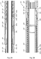
- Figures 2A and 2B depict a cross-sectional view of layout of a travel joint assembly 23 in accordance with an illustrative embodiment of the present disclosure.
- the portion of the travel joint assembly 23 shown in Figure 2A is located uphole relative to the portion of the travel joint assembly 23 shown in Figure 2B and is referred to herein as an upper portion of the travel joint assembly 23.
- the term "upper portion” as used herein refers to the distal end of the travel joint assembly 23 that is located uphole relative to the opposing distal end. Accordingly, the terminology is equally applicable to deviated or horizontal wellbores and the present disclosure is not limited to vertical wellbores.
- the travel joint assembly 23 may comprise an inner mandrel 210.
- the travel joint assembly 23 may include an outer housing 220 extending outside the inner mandrel 210.
- An inner control line coil 230 and an outer control line coil 240 may run along the outer surface of the inner mandrel 210 between the inner mandrel 210 and the outer housing 220.
- the inner control line coil 230 and an outer control line coil 240 may be wrapped around the outer surface of the inner mandrel 210.
- the inner mandrel 210 may be positioned inside the inner control line coil 230 and the outer control line coil 240 may be installed over the inner control line coil 230.
- the inner control line coil 230 includes three distinct control lines denoted as 230a, 230b, 230c.
- the outer control line coil 240 includes a single control line.
- the present disclosure is not limited to any specific number of control lines in each of the inner control line coil 230 and the outer control line coil 240 and more or fewer control lines may be utilized in each coil without departing from the scope of the present disclosure.
- a straight length of control line 235a, 235b, 235c (shown in Figure 3B ) corresponding to each of the control lines 230a, 230b, 230c of the inner control line coil 230 may extend along the outside of the inner mandrel 210.
- the straight length of control lines 235a, 235b, 235c are collectively referred to as the inner straight length of control line 235.
- the straight length of control line 235a is shown in Figure 2A for illustrative purposes while the straight length of control line 235b and 235c are depicted in Figure 3B .
- Each of the straight length of control lines 235a, 235b, 235c may be coupled to an upper bushing 250.
- the upper bushing 250 (shown in Figure 3B ) extends along an outer surface of the inner mandrel.
- each of the straight length of control lines 235a, 235b, 235c may be coupled to the upper bushing 250 using corresponding anchor blocks 304a, 304b, 304c before it bends and becomes one of the control lines 230a, 230b, 230c of the inner control line coil 230.
- an outer straight length of control line 245 corresponding to outer control line coil 240 may extend along the outside of the inner mandrel 210.
- the outer straight length of control line 245 may be coupled to the upper bushing 250 using any suitable means, such as an anchor block 304d, in the same manner discussed above with respect to the straight length of control line 235a.
- the outer straight length of control line 245 may be coupled to the upper bushing 250 with an anchor block 304d (shown in Figure 3A ) before bending to become a part of the outer control line coil 240.
- the configuration of the upper bushing 250 and the anchor blocks 304a-d is discussed in more detail below.
- the inner straight length of control line 235 and the outer straight length of control line 245 may be directed downhole through an upper sub 260 and may each be sealingly fixed to the upper sub 260 by a corresponding control line fitting 270 as shown in Figure 2A .
- the control line fitting 270 may be a swedge-lok type fitting, high integrity flange (HIF) fitting, or similar fitting that swedges on a ferrel fitting to anchor and seal the inner straight length of control line 235 and the outer straight length of control line 245 to the upper sub 260.
- the upper sub 260 may be threadingly coupled to the outer housing 220 and tubing string 12.
- the inner straight length of control line 235 and the outer straight length of control line 245 may continue to extend along the tubing string 12 and may be secured thereto with any suitable means including, but not limited to, cable clamps (not shown).
- Figure 2B depicts a cross sectional view of a lower end of the travel joint assembly 23 in accordance with an illustrative embodiment of the present disclosure.
- the inner straight length of control line 235 and the outer straight length of control line 245 extend into control lines 230a, 230b, 230c of the inner control line coil 230 and the outer control line coil 240 at the lower end of the travel joint assembly 23.
- the outer housing 220 and the inner mandrel 210 are continuous from Fig 2A .
- the actual length of these components may depend on the amount of expansion or contraction needed for the travel joint assembly 23.
- the outer control line coil 240 may be coiled around the inner mandrel 210 on top of the inner control line coil 230 in the same manner discussed above in conjunction with Figure 2A .
- the outer control line coil 240 may be wound on top of the inner control line coil 230 on the inner mandrel 210.
- the inner control line coil 230 and the outer control line coil 240 may be wound clockwise or counter-clockwise and one or both of the coils may be encapsulated.
- the inner control line coil 230 and the outer control line coil 240 may be wound in opposite directions around the inner mandrel 210 in order to minimize interference or nesting during expansion and contraction.
- the inner control line coil 230 may be wound clockwise around the inner mandrel 210 and the outer control line coil 240 may be wound counter-clockwise around both the inner mandrel 210 and the inner control line coil 230.
- inner control line coil 230 may be wound counter-clockwise around the inner mandrel 210 and the outer control line coil 240 may be wound clockwise around both the inner mandrel 210 and the inner control line coil 230.
- the inner control line coil 230 and the outer control line coil 240 may be arranged so as to permit a telescoping movement of the inner mandrel 210 and the outer housing 220.
- FIG. 3A a perspective view of an upper portion (also referred to as the "top sub") of the travel joint assembly 23 in accordance with an implementation of the present disclosure is depicted.
- the outer control line coil 240 may be coupled to the upper bushing 250 through an anchor block 304d and fixed thereto with a anchor block fitting 306.
- the upper bushing 250 may include additional anchor blocks 304e, 304f.
- the additional anchor blocks 304e, 304f are left unused in the illustrative embodiment of Figure 3A , if desirable, they facilitate implementation of additional control lines in the outer control line coil 240.
- the anchor blocks 304d, 304e, 304f may be coupled to the upper bushing 250 with any suitable means.
- the anchor blocks 304d, 304e, 304f may be coupled to the upper bushing 250 with one or more removable or permanent fasteners.
- the anchor blocks 304d, 304e, 304f may be welded to the upper bushing 250.
- the outer straight length of control line 245 extends from the anchor block 304d along the outer surface of the upper bushing 250 to the upper sub 260.
- FIG 3B shows a perspective view of the top sub of the travel joint assembly 23 of Figure 3A with the outer control line coil 240 removed.
- each of the control lines 230a, 230b, 230c of the inner control line coil 230 may be coupled to the upper bushing 250 using a corresponding anchor block 304a, 304b, 304c, respectively.
- Each of the control lines 230a, 230b, 230c may transition from the inner control line coil 230 to a corresponding straight length of control line 235a, 235b, 235c as shown in Figure 3B .
- the anchor blocks 304a, 304b, 304c may be coupled to the upper bushing 250 with any suitable means. In certain implementations, the anchor blocks 304a, 304b, 304c may be coupled to the upper bushing 250 with fasteners or may be welded.
- the outer control line coil 240 is removed from Figure 3B for illustrative purposes.
- the control lines coils 230, 240 may be encapsulated with plastic or elastomeric material to prevent damage from rubbing or material loss from chaffing.
- the plastic encapsulation my be formed of high density polyethylene (HDPE), polyethylenechlorotriflouroethylene (ECTFE), Polyamide (Nylon), Flourinated ethylene proplylene (FEP), polyvinyl chloride (PVC), polyvinylidene fluoride (PVDF), Polyethylenetetraflouroethylene (ETFE), other polymeric compounds.
- the encapsulation may be formed from elastomeric materials, including, but not limited to, neoprene, nitriles, Ethylene propylene diene monomer (EPDM), flouroelastomers (FKM) and/or perfluoroelastomers (FFKM), polytetrafluorethylene (PTFE), polyether ether ketone (PEEK), and/or other elastomeric materials.
- EPDM Ethylene propylene diene monomer
- FKM flouroelastomers
- FFKM perfluoroelastomers
- PTFE polytetrafluorethylene
- PEEK polyether ether ketone
- the transition bend of the inner straight length of control line 235 and the outer straight length of control line 245 to the inner and the outer control line coils 230, 240 may need to be controlled to prevent fatigue failure.
- the outer control line coil 240 and the inner control line coil 230 may each be supported radially by a corresponding outside surface 310, 320 of the upper bushing 250.
- the upper bushing 250 may include grooves 502 that accommodate the end of control lines from the inner control line coil 230 and the outer control line coil 240 before a first transition bend 330a-c and 340 where each coil transitions into the inner straight length of control line 235 and the outer straight length of control line 245, respectively.
- the upper bushing 250 may secure and separate a number of different control lines for axial movement.
- the upper bushing 250 separates four control lines (230a-c, 240a) in Figures 3A and 3B
- any desired number of control lines may be separated in a similar manner without departing from the scope of the present disclosure.
- the disclosed method and system of securing control lines is scalable to allow for additional control lines to be added. For instance, although not illustrated, in certain embodiments, an assembly could have a total of six control lines with each of the inner control line coil 230 and outer control line coil 240 having three control lines.
- the anchor blocks 304a-f may be distributed radially along an outer perimeter of the upper bushing 250. Specifically, each of the anchor blocks 304a-f may be placed at a different radial location along the outer perimeter of the upper bushing 250. This distribution of the anchor blocks 304a-f permits each control line from the inner control line coil 230 and the outer control line coil 240 to transition into a corresponding straight length of control line at a different location along the outer perimeter of the upper bushing 250, making the control lines of the control line coils 230, 240 less susceptible to tension.
- the radial distribution of anchor blocks 304a-f controls the winding of the control lines from the inner and outer control line coils 230, 240. This helps prevent nesting or control lines trying to slip over or on top of other control lines.
- the anchor blocks 304a-f and control line fittings 270 attach the control lines to the upper bushing 250 and transfers the tension from the control line coils 230, 240 to the upper bushing 250.
- the straight lengths of control line 235, 245 is isolated from the tension resulting from the weight of the control lines and the stiffness of the coils 230, 240 (acting like a spring) as the travel joint assembly 23 extends.
- control line 235, 245 might cause the control lines 230a-c, 240a to slip from the control line fitting 270 and start leaking. If one of the control lines slips from control line fitting 270, the control line coils 230, 240 may become misaligned and start interfering with each other.
- the specific distribution configuration of the anchor blocks 304a-f shown in Figures 3A and 3B is shown for illustrative purposes only. The distribution of the anchor blocks 304a-f along the outer perimeter of the upper bushing 250 may be altered without departing from the scope of the present disclosure.
- FIG 4 depicts a close up view of an anchor block 304 that may be used in conjunction with the travel joint assembly 23 in accordance with an embodiment of the present disclosure.
- the anchor block fittings 306 may be installed to anchor the straight length of control lines 235, 245 into an opening 402 of the anchor block 304.
- the anchor block 304 may have multiple fittings (e.g., HIF fittings or wide HIF fittings) to hold multiple control lines in place.
- the anchor block fittings 306 may be made from any suitable material.
- the anchor block fittings 306 may be made from nickel alloy steel (Inconel), stainless steel, alloy steel, or a combination thereof.
- the anchor blocks 304 may be configured to sit in a corresponding recess 504 of the upper bushing 250.
- FIGS 5A and 5B depict a perspective view of a lower portion of the travel joint assembly 23 in accordance with an illustrative embodiment of the present disclosure.
- the control lines 230a-c of the inner control line coil 230 are supported by the lower bushing 280.
- the control lines 230a-c may transition from the inner control line coil 230 to corresponding straight length of control line 235a, 235b, 235c passing under a clamp 520.
- Each of the straight length of control line 235a, 235b, 235c may be anchored and sealed to the lower sub 295 by a corresponding control line fitting 270.
- the outer control line coil 240 passes over the inner control line coil 230.
- the outer control line coil 240 may be supported by the lower bushing 280 and the outside surface of the clamp 520.
- the outer control line may transition from the outer control line coil 240 to the straight length of control line 245 and may be secured by any suitable means known to those of ordinary skill in the art.
- the straight length of control line 245 may be secured by a first clamp 530 and a second clamp 540.
- the straight length of control line 245 may be sealingly secured to the lower sub 295 by a control line fitting 270.
- the clamp 540 may align the straight length of control line 245 with the control line fitting 270.
- the clamp 530 may hold the clamp 540 in place and be secured to the lower bushing 280 by one or more fasteners.
- the lower bushing 280 may separate the four control lines 230a-c, 240a and prevent them from nesting or rubbing while moving.
- Figure 5A illustrates three control line fittings 270 where the inner control lines 230a-c pass into the lower sub 295.
- the control line from the outer control line coil 240 may pass into the lower sub 295 through a control line fitting 270.
- the control line fittings 270 may be HIF fittings.
- the control line fittings 270 are capable of isolating the tubing pressure from the annulus pressure when the travel joint assembly 23 is extended.
- each of the inner control line coil 230 and the outer control line coil 240 is wrapped around an outer surface of the inner mandrel and includes a first portion located uphole relative to the upper bushing and a second portion located downhole relative to the lower bushing.
- the first portion and the second portion of the inner control line coil 230 and the outer control line coil 240 are separated by an inner straight length of control line 235 and an outer straight length of control line 245.
- the distal ends of the inner straight length of control line 235 and the outer straight length of control line 245 are coupled to the upper bushing 250 and the lower bushing 280 using a fastener.
- anchor blocks 304 and control line fittings 270 may be used to couple the inner straight length of control line 235 and the outer straight length of control line 245 to the upper bushing 250.
- control line fittings 270 and one or more clamps 520, 530, 540 may be used to couple the inner straight length of control line 235 and the outer straight length of control line 245 to the lower bushing 280. This configuration minimizes tension in the inner control line coil 230 and the outer control line coil 240 as the travel joint assembly 23 moves between its extended and compressed position.
- the method and system disclosed herein may be used to effectively transmit any desired signals from a first axial location along a wellbore to a second axial location thereof across a travel joint that is movable between an expanded and a contracted position.
- the anchor blocks 304a-f and the clamps 520, 530, 540 couple the control lines from the inner control line coil 230 and the outer control line coil 240 to the upper bushing 250 and the lower bushing 280.
- This configuration isolates the tension from the expanding and contracting control lines as well as the weight of the control lines.
- the control line fittings 270 that provide a pressure seal at the upper sub 260 and the lower sub 295 remain static and are therefore isolated from tension.
- control line coil 230 may be used without departing from the scope of the present disclosure.
- three or more control line coils may be used in a similar manner.
- a single control line coil may be used without departing from the scope of the present disclosure.
- either one of the inner control line coil 230 or the outer control line coil 240 may be eliminated.
- the present disclosure is not limited to any specific wellbore orientation.
- the methods and systems disclosed herein are equally applicable to wellbores having any orientation including, but not limited to, vertical wellbores, slanted wellbores, or multilateral wellbores. Accordingly, the directional terms such as “above”, “below”, “upper”, “lower”, “upward”, “downward”, “uphole”, and “downhole” are used for illustrative purposes only to describe the illustrative embodiments as they are depicted in the figures.
- an offshore operation is depicted in the illustrative embodiment of Figure 1
- the methods and systems disclosed herein are equally applicable to onshore operations.
- the methods and systems disclosed herein are equally applicable to a cased hole completion and an open hole completion without departing from the scope of the present disclosure.
Landscapes
- Engineering & Computer Science (AREA)
- Geology (AREA)
- Life Sciences & Earth Sciences (AREA)
- Mining & Mineral Resources (AREA)
- Physics & Mathematics (AREA)
- Environmental & Geological Engineering (AREA)
- Fluid Mechanics (AREA)
- Mechanical Engineering (AREA)
- General Life Sciences & Earth Sciences (AREA)
- Geochemistry & Mineralogy (AREA)
- Earth Drilling (AREA)
- Replacement Of Web Rolls (AREA)
- Spray Control Apparatus (AREA)
Description
- A Travel joint may be used in a production tubing string for installing a tubing hanger inside a wellhead after installing the production tubing string inside the completion equipment. The travel joint allows the production tubing string to shorten by axially telescoping the assembly. A Travel joint may be deployed from the surface in an extended position. The travel joint may then be released for telescoping or longitudinally collapsing by any suitable means. For instance, mechanical devices such as shear pins, J-Slots, metered hydraulic time releases, etc., may be used to manipulate the travel joint.
- When performing subterranean operations, control lines may be coupled to the outside of the production tubing string to provide a path for power and/or data communication to various flow control devices and/or gauges attached to the production tubing string or the completion equipment downhole. In certain implementations, the control lines may be securely clamped to the outside of the production tubing string. The control lines may include electric cables, hydraulic cables, fiber optic cables, or a combination thereof. For instance, electric and/or hydraulic cables may provide power to various flow control devices downhole to control the rate of production flow into the production tubing string. Similarly, electric and/or fiber optic cables may transmit data from one or more sensors downhole relating to reservoir and fluid properties such as, for example, pressure, temperature, density, flow rate, fluid composition, and/or water content.
- It is often desirable for one or more control lines to pass along a travel joint. However, the axial movements of the travel joint may prove problematic when directing control lines along the travel joint. Specifically, unlike the travel joint, the control lines are typically not extendable/retractable. This problem may be magnified in instances when multiple control lines need to traverse a travel joint. It may be particularly difficult for multiple control lines to traverse a travel joint due, in part, to the differences in the properties of electric, hydraulic, and fiber optic control lines such as differences in stiffness. It is therefore desirable to develop methods and systems to facilitate installation of one or more control lines that effectively traverse a travel joint.
- Some specific example embodiments of the disclosure may be understood by referring, in part, to the following description and the accompanying drawings.
-
Figure 1 depicts a system for performing subterranean operations in accordance with an illustrative embodiment of the present disclosure. -
Figures 2A and 2B depict a cross-sectional view of layout of a travel joint assembly in accordance with an illustrative embodiment of the present disclosure. -
Figure 3A depicts a perspective view of an upper portion (also referred to as the "top sub") of the travel joint assembly ofFigure 2A in accordance with an illustrative embodiment of the present disclosure. -
Figure 3B shows a perspective view of the top sub of the travel joint assembly ofFigure 3A with the outer control line coil removed. -
Figure 4 depicts a close up view of an anchor block used in conjunction with a travel joint assembly in accordance with an illustrative embodiment of the present disclosure. -
Figures 5A and5B depict perspective views of a lower portion (also referred to as the "lower sub") of the travel joint assembly ofFigure 2B in accordance with an illustrative embodiment of the present disclosure. - While embodiments of this disclosure have been depicted and described and are defined by reference to exemplary embodiments of the disclosure, such references do not imply a limitation on the disclosure, and no such limitation is to be inferred. The subject matter disclosed is capable of considerable modification, alteration, and equivalents in form and function, as will occur to those skilled in the pertinent art and having the benefit of this disclosure. The depicted and described embodiments of this disclosure are examples only, and not exhaustive of the scope of the disclosure.
- To facilitate a better understanding of the present invention, the following examples of certain embodiments are given. In no way should the following examples be read to limit, or define, the scope of the invention. Embodiments of the present disclosure may be applicable to horizontal, vertical, deviated, or otherwise nonlinear wellbores in any type of subterranean formation. Embodiments may be applicable to injection wells as well as production wells, including hydrocarbon wells. Embodiments may be implemented with tools that, for example, may be conveyed through a flow passage in tubular string or coiled tubing, downhole robot or the like.
- For the purposes of this disclosure, the terms "couple" or "couples," as used herein are intended to mean either an indirect or a direct connection. Thus, if a first device couples to a second device, that connection may be through a direct connection, or through an indirect electrical connection via other devices and connections. The term "uphole" as used herein means along the drillstring or the hole from the distal end towards the surface, and "downhole" as used herein means along the drillstring or the hole from the surface towards the distal end.
- The methods and systems disclosed herein may be used in conjunction with production, monitoring, or injection in relation to the recovery of hydrocarbons or other materials from the subsurface.
- Illustrative embodiments of the present invention are described in detail herein. In the interest of clarity, not all features of an actual implementation may be described in this specification. It will of course be appreciated that in the development of any such actual embodiment, numerous implementation-specific decisions may be made to achieve the specific implementation goals, which may vary from one implementation to another. Moreover, it will be appreciated that such a development effort might be complex and time-consuming, but would nevertheless be a routine undertaking for those of ordinary skill in the art having the benefit of the present disclosure.
- The present invention relates generally to spacing out operations and, more particularly, to method and system for installing one or more control lines on a travel joint.
- Turning now to
Figure 1 , a system for performing subterranean operations in accordance with an illustrative embodiment of the present disclosure is denoted generally withreference numeral 10. In thesystem 10, atubular string 12 extends downwardly from adrilling rig 14. Thedrilling rig 14 may be a floating platform, drill ship, or jack up rig. In certain illustrative embodiments, thetubular string 12 may be in a riser (not shown) between thedrilling rig 14 and awellhead 16. In other embodiments, a riser may not be used. - The
tubular string 12 may be stabbed into acompletion assembly 18 previously installed in awellbore 20. In the illustrative embodiment ofFigure 1 , thetubular string 12 is sealingly received in apacker 22 at an upper end of thecompletion assembly 18. In certain embodiments, thetubular string 12 may have a seal stack (not shown) thereon which seals within a sealed bore receptacle (e.g., above a liner hanger, etc.). Thetubular string 12 may be connected with thecompletion assembly 18 using any suitable means known to those of ordinary skill in the art, having the benefit of the present disclosure, without departing from the scope of the present disclosure. - The
completion assembly 18 may be used to "complete" a portion of thewellbore 20. Completing a wellbore, as used herein, refers to operations performed to prepare the wellbore for production or injection operations. Thecompletion assembly 18 may include one or more elements which facilitate such production or injection operations. For instance, thecompletion assembly 18 may comprise elements including, but not limited to, packers, well screens, perforated liner or casing, production or injection valves, flow control devices, and/or chokes. - A
travel joint system 23 may be used to axially shorten thetubular string 12 between thecompletion assembly 18 and thewellhead 16. After thetubular string 12 has been connected to thecompletion assembly 18, atravel joint 24 in thetubular string 12 may be released to allow thetubular string 12 to be landed in thewellhead 16. In the example ofFig. 1 , ahanger 26 is landed on a wear bushing 28, but other manners of securing a tubular string in a wellhead which are known to those of ordinary skill in the art having the benefit of the present disclosure may be used without departing from the scope of the present disclosure. - The
travel joint 24 permits some variation in the length of thetubular string 12 between thehanger 26 and thecompletion assembly 18. For instance, thetravel joint 24 may allow the length of thetubular string 12 to shorten after thecompletion assembly 18 has been sealingly engaged, so that thehanger 26 can be appropriately landed in thewellhead 16. - The
travel joint 24 may be any suitable travel joint. For instance, in certain implementations, thetravel joint 24 may be the travel joint disclosed inU.S. Patent No. 6,540,025 , assigned to Halliburton Energy Services, Inc. The illustrative travel joint disclosed inU.S. Patent No. 6,540,025 includes a hydraulic release device which releases the travel joint in response to a predetermined compressive force being applied to the travel joint for a predetermined amount of time. The described travel joint also includes a resetting feature which permits the travel joint to be locked back in its extended configuration after having been compressed. - In certain implementations, the
travel joint 24 of thesystem 10 may be comprised of other types of release mechanisms. For instance, in certain embodiments, the travel joint 24 may be one which is released in response to shearing one or more shear pins/screws with axial tension or compression. Alternatively, the travel joint 24 may be configured to be released by means of a j-slot or ratchet. Operation of such travel joints is well known to those of ordinary skill in the art, having the benefit of the present disclosure, and will therefore not be discussed in detail herein. As discussed in more detail below, the travel joint 24 is configured to facilitate passage of one or more control lines therethrough while preserving operational integrity. -
Figures 2A and 2B depict a cross-sectional view of layout of a traveljoint assembly 23 in accordance with an illustrative embodiment of the present disclosure. The portion of the traveljoint assembly 23 shown inFigure 2A is located uphole relative to the portion of the traveljoint assembly 23 shown inFigure 2B and is referred to herein as an upper portion of the traveljoint assembly 23. The term "upper portion" as used herein refers to the distal end of the traveljoint assembly 23 that is located uphole relative to the opposing distal end. Accordingly, the terminology is equally applicable to deviated or horizontal wellbores and the present disclosure is not limited to vertical wellbores. As shown inFigure 2A , the traveljoint assembly 23 may comprise aninner mandrel 210. At its upper portion, the traveljoint assembly 23 may include anouter housing 220 extending outside theinner mandrel 210. An innercontrol line coil 230 and an outercontrol line coil 240 may run along the outer surface of theinner mandrel 210 between theinner mandrel 210 and theouter housing 220. As shown inFigure 2A , in certain implementations, the innercontrol line coil 230 and an outercontrol line coil 240 may be wrapped around the outer surface of theinner mandrel 210. Theinner mandrel 210 may be positioned inside the innercontrol line coil 230 and the outercontrol line coil 240 may be installed over the innercontrol line coil 230. - In the illustrative implementation of
Figures 2A and 2B , the innercontrol line coil 230 includes three distinct control lines denoted as 230a, 230b, 230c. In contrast, in the illustrative embodiments ofFigures 2A and 2B , the outercontrol line coil 240 includes a single control line. However, the present disclosure is not limited to any specific number of control lines in each of the innercontrol line coil 230 and the outercontrol line coil 240 and more or fewer control lines may be utilized in each coil without departing from the scope of the present disclosure. - A straight length of
control line Figure 3B ) corresponding to each of thecontrol lines control line coil 230 may extend along the outside of theinner mandrel 210. The straight length ofcontrol lines control line 235. The straight length ofcontrol line 235a is shown inFigure 2A for illustrative purposes while the straight length ofcontrol line Figure 3B . Each of the straight length ofcontrol lines upper bushing 250. The upper bushing 250 (shown inFigure 3B ) extends along an outer surface of the inner mandrel. In certain embodiments, each of the straight length ofcontrol lines upper bushing 250 usingcorresponding anchor blocks control lines control line coil 230. - Additionally, as shown in
Figure 2A , an outer straight length ofcontrol line 245 corresponding to outercontrol line coil 240 may extend along the outside of theinner mandrel 210. The outer straight length ofcontrol line 245 may be coupled to theupper bushing 250 using any suitable means, such as ananchor block 304d, in the same manner discussed above with respect to the straight length ofcontrol line 235a. Specifically, the outer straight length ofcontrol line 245 may be coupled to theupper bushing 250 with ananchor block 304d (shown inFigure 3A ) before bending to become a part of the outercontrol line coil 240. The configuration of theupper bushing 250 and the anchor blocks 304a-d is discussed in more detail below. - The inner straight length of
control line 235 and the outer straight length ofcontrol line 245 may be directed downhole through anupper sub 260 and may each be sealingly fixed to theupper sub 260 by a corresponding control line fitting 270 as shown inFigure 2A . In certain embodiments, the control line fitting 270 may be a swedge-lok type fitting, high integrity flange (HIF) fitting, or similar fitting that swedges on a ferrel fitting to anchor and seal the inner straight length ofcontrol line 235 and the outer straight length ofcontrol line 245 to theupper sub 260. Theupper sub 260 may be threadingly coupled to theouter housing 220 andtubing string 12. The inner straight length ofcontrol line 235 and the outer straight length ofcontrol line 245 may continue to extend along thetubing string 12 and may be secured thereto with any suitable means including, but not limited to, cable clamps (not shown). -
Figure 2B depicts a cross sectional view of a lower end of the traveljoint assembly 23 in accordance with an illustrative embodiment of the present disclosure. The inner straight length ofcontrol line 235 and the outer straight length ofcontrol line 245 extend intocontrol lines control line coil 230 and the outercontrol line coil 240 at the lower end of the traveljoint assembly 23. Theouter housing 220 and theinner mandrel 210 are continuous fromFig 2A . The actual length of these components may depend on the amount of expansion or contraction needed for the traveljoint assembly 23. As can be seen inFigure 2B , the outercontrol line coil 240 may be coiled around theinner mandrel 210 on top of the innercontrol line coil 230 in the same manner discussed above in conjunction withFigure 2A . - Similar to the configuration of the upper portion of the travel
joint assembly 23, in the lower portion, the straight length ofcontrol lines control line coil 230 and pass through alower bushing 280 and a lower sub 295 (as shown inFigure 2B ). Like theupper bushing 250, thelower bushing 280 extends along an outer surface of theinner mandrel 210. The straight length ofcontrol lines lower sub 295 by correspondingcontrol line fittings 270. Similarly, the outer straight length ofcontrol line 245 may extend from the outercontrol line coil 240 and may be fixed to thelower sub 295 by a control line fitting 270. - As shown in
Figures 2A and 2B , the outercontrol line coil 240 may be wound on top of the innercontrol line coil 230 on theinner mandrel 210. In certain embodiments, the innercontrol line coil 230 and the outercontrol line coil 240 may be wound clockwise or counter-clockwise and one or both of the coils may be encapsulated. In certain embodiments, the innercontrol line coil 230 and the outercontrol line coil 240 may be wound in opposite directions around theinner mandrel 210 in order to minimize interference or nesting during expansion and contraction. For instance, the innercontrol line coil 230 may be wound clockwise around theinner mandrel 210 and the outercontrol line coil 240 may be wound counter-clockwise around both theinner mandrel 210 and the innercontrol line coil 230. In other embodiments, innercontrol line coil 230 may be wound counter-clockwise around theinner mandrel 210 and the outercontrol line coil 240 may be wound clockwise around both theinner mandrel 210 and the innercontrol line coil 230. Additionally, in certain embodiments, the innercontrol line coil 230 and the outercontrol line coil 240 may be arranged so as to permit a telescoping movement of theinner mandrel 210 and theouter housing 220. - Turning now to
Figure 3A , a perspective view of an upper portion (also referred to as the "top sub") of the traveljoint assembly 23 in accordance with an implementation of the present disclosure is depicted. The outercontrol line coil 240 may be coupled to theupper bushing 250 through ananchor block 304d and fixed thereto with a anchor block fitting 306. As shown inFigure 3A , theupper bushing 250 may includeadditional anchor blocks additional anchor blocks Figure 3A , if desirable, they facilitate implementation of additional control lines in the outercontrol line coil 240. The anchor blocks 304d, 304e, 304f may be coupled to theupper bushing 250 with any suitable means. In certain implementations, the anchor blocks 304d, 304e, 304f may be coupled to theupper bushing 250 with one or more removable or permanent fasteners. For instance, in certain implementations, the anchor blocks 304d, 304e, 304f may be welded to theupper bushing 250. The outer straight length ofcontrol line 245 extends from theanchor block 304d along the outer surface of theupper bushing 250 to theupper sub 260. -
Figure 3B shows a perspective view of the top sub of the traveljoint assembly 23 ofFigure 3A with the outercontrol line coil 240 removed. As shown inFigure 3B , each of thecontrol lines control line coil 230 may be coupled to theupper bushing 250 using acorresponding anchor block control lines control line coil 230 to a corresponding straight length ofcontrol line Figure 3B . The anchor blocks 304a, 304b, 304c may be coupled to theupper bushing 250 with any suitable means. In certain implementations, the anchor blocks 304a, 304b, 304c may be coupled to theupper bushing 250 with fasteners or may be welded. The outercontrol line coil 240 is removed fromFigure 3B for illustrative purposes. - The control lines coils 230, 240 may be encapsulated with plastic or elastomeric material to prevent damage from rubbing or material loss from chaffing. Specifically, in certain implementations, the plastic encapsulation my be formed of high density polyethylene (HDPE), polyethylenechlorotriflouroethylene (ECTFE), Polyamide (Nylon), Flourinated ethylene proplylene (FEP), polyvinyl chloride (PVC), polyvinylidene fluoride (PVDF), Polyethylenetetraflouroethylene (ETFE), other polymeric compounds. In other embodiments, the encapsulation may be formed from elastomeric materials, including, but not limited to, neoprene, nitriles, Ethylene propylene diene monomer (EPDM), flouroelastomers (FKM) and/or perfluoroelastomers (FFKM), polytetrafluorethylene (PTFE), polyether ether ketone (PEEK), and/or other elastomeric materials. The encapsulation may be removed the points of transition between the control line coils 230, 240 and their corresponding inner straight length of
control line 235 and outer straight length ofcontrol line 245 to permit the anchor blocks 304a-f to anchor onto the bare control line. - As shown in
Figures 3A and3B , each of the anchor blocks 304a-f may include a corresponding anchor block fitting 306a-f (collectively referred to as "anchor block fittings 306"). Theanchor block fittings 306 anchor the control lines of each of the outercontrol line coil 240 and the innercontrol line coil 230 to acorresponding anchor block 304. Theanchor block fittings 306 and the anchor blocks 304 prevent tension in the control lines of the innercontrol line coil 230 and the outercontrol line coil 240 from transferring tofittings 270. Thefittings 270 in theupper sub 260 provide a pressure seal between tubing and annulus pressure. In order to avoid damaging thefittings 270 by tension and flexure of the straight lengths ofcontrol line upper bushing 250 byanchor block 304 andanchor block fittings 306, as discussed above. - In addition, the transition bend of the inner straight length of
control line 235 and the outer straight length ofcontrol line 245 to the inner and the outer control line coils 230, 240 may need to be controlled to prevent fatigue failure. Specifically, the outercontrol line coil 240 and the innercontrol line coil 230 may each be supported radially by a correspondingoutside surface upper bushing 250. For instance, in certain implementations as shown inFigures 3A and3B , theupper bushing 250 may includegrooves 502 that accommodate the end of control lines from the innercontrol line coil 230 and the outercontrol line coil 240 before afirst transition bend 330a-c and 340 where each coil transitions into the inner straight length ofcontrol line 235 and the outer straight length ofcontrol line 245, respectively. This radial support fromsurface coils coils control lines 230a-c, 240a would want to bend in the radial direction. -
Figures 3A and3B illustrate how multiple control lines may be coiled around a singleinner mandrel 210 and avoid nesting or rubbing while theinner mandrel 210 is moved. As can be seen inFigure 3B , thecontrol lines 230a-c of the innercontrol line coil 230 may be threaded throughanchor block fittings 306 of corresponding anchor blocks 304a-c. In certain implementations, theupper bushing 250 may includerecesses 504a-f to house the anchor blocks 304a-f. Similarly, the outer control line from the outercontrol line coil 240 may be threaded through a fitting 306d of anotheranchor block 304d installed in arecess 504d of theupper bushing 250. - As shown in
Figures 3A and3B , theupper bushing 250 may secure and separate a number of different control lines for axial movement. Although theupper bushing 250 separates four control lines (230a-c, 240a) inFigures 3A and3B , any desired number of control lines may be separated in a similar manner without departing from the scope of the present disclosure. Specifically, the disclosed method and system of securing control lines is scalable to allow for additional control lines to be added. For instance, although not illustrated, in certain embodiments, an assembly could have a total of six control lines with each of the innercontrol line coil 230 and outercontrol line coil 240 having three control lines. - Moreover, as shown in
Figures 3A and3B , the anchor blocks 304a-f may be distributed radially along an outer perimeter of theupper bushing 250. Specifically, each of the anchor blocks 304a-f may be placed at a different radial location along the outer perimeter of theupper bushing 250. This distribution of the anchor blocks 304a-f permits each control line from the innercontrol line coil 230 and the outercontrol line coil 240 to transition into a corresponding straight length of control line at a different location along the outer perimeter of theupper bushing 250, making the control lines of the control line coils 230, 240 less susceptible to tension. Specifically, the radial distribution ofanchor blocks 304a-f controls the winding of the control lines from the inner and outer control line coils 230, 240. This helps prevent nesting or control lines trying to slip over or on top of other control lines. The anchor blocks 304a-f and controlline fittings 270 attach the control lines to theupper bushing 250 and transfers the tension from the control line coils 230, 240 to theupper bushing 250. As a result, the straight lengths ofcontrol line coils 230, 240 (acting like a spring) as the traveljoint assembly 23 extends. The tension in the straight lengths ofcontrol line control lines 230a-c, 240a to slip from the control line fitting 270 and start leaking. If one of the control lines slips from control line fitting 270, the control line coils 230, 240 may become misaligned and start interfering with each other. The specific distribution configuration of the anchor blocks 304a-f shown inFigures 3A and3B is shown for illustrative purposes only. The distribution of the anchor blocks 304a-f along the outer perimeter of theupper bushing 250 may be altered without departing from the scope of the present disclosure. -
Figure 4 depicts a close up view of ananchor block 304 that may be used in conjunction with the traveljoint assembly 23 in accordance with an embodiment of the present disclosure. Theanchor block fittings 306 may be installed to anchor the straight length ofcontrol lines opening 402 of theanchor block 304. In certain embodiments, theanchor block 304 may have multiple fittings (e.g., HIF fittings or wide HIF fittings) to hold multiple control lines in place. Theanchor block fittings 306 may be made from any suitable material. For instance, in certain implementations, theanchor block fittings 306 may be made from nickel alloy steel (Inconel), stainless steel, alloy steel, or a combination thereof. As discussed above and depicted inFigures 3A and3B , the anchor blocks 304 may be configured to sit in a corresponding recess 504 of theupper bushing 250. -
Figures 5A and5B depict a perspective view of a lower portion of the traveljoint assembly 23 in accordance with an illustrative embodiment of the present disclosure. Thecontrol lines 230a-c of the innercontrol line coil 230 are supported by thelower bushing 280. In certain implementations, thecontrol lines 230a-c may transition from the innercontrol line coil 230 to corresponding straight length ofcontrol line clamp 520. Each of the straight length ofcontrol line lower sub 295 by a corresponding control line fitting 270. - In the lower portion of the travel
joint assembly 23 as with the upper portion, the outercontrol line coil 240 passes over the innercontrol line coil 230. As shown inFigure 5B , the outercontrol line coil 240 may be supported by thelower bushing 280 and the outside surface of theclamp 520. The outer control line may transition from the outercontrol line coil 240 to the straight length ofcontrol line 245 and may be secured by any suitable means known to those of ordinary skill in the art. For instance, in certain embodiments, the straight length ofcontrol line 245 may be secured by afirst clamp 530 and asecond clamp 540. The straight length ofcontrol line 245 may be sealingly secured to thelower sub 295 by a control line fitting 270. Theclamp 540 may align the straight length ofcontrol line 245 with the control line fitting 270. Theclamp 530 may hold theclamp 540 in place and be secured to thelower bushing 280 by one or more fasteners. - Like the
upper bushing 250, thelower bushing 280 may separate the fourcontrol lines 230a-c, 240a and prevent them from nesting or rubbing while moving.Figure 5A illustrates threecontrol line fittings 270 where theinner control lines 230a-c pass into thelower sub 295. Similarly, the control line from the outercontrol line coil 240 may pass into thelower sub 295 through a control line fitting 270. In certain implementations, thecontrol line fittings 270 may be HIF fittings. Thecontrol line fittings 270 are capable of isolating the tubing pressure from the annulus pressure when the traveljoint assembly 23 is extended. - Accordingly, each of the inner
control line coil 230 and the outercontrol line coil 240 is wrapped around an outer surface of the inner mandrel and includes a first portion located uphole relative to the upper bushing and a second portion located downhole relative to the lower bushing. The first portion and the second portion of the innercontrol line coil 230 and the outercontrol line coil 240 are separated by an inner straight length ofcontrol line 235 and an outer straight length ofcontrol line 245. The distal ends of the inner straight length ofcontrol line 235 and the outer straight length ofcontrol line 245 are coupled to theupper bushing 250 and thelower bushing 280 using a fastener. For instance, in certain implementations, anchor blocks 304 andcontrol line fittings 270 may be used to couple the inner straight length ofcontrol line 235 and the outer straight length ofcontrol line 245 to theupper bushing 250. Similarly,control line fittings 270 and one ormore clamps control line 235 and the outer straight length ofcontrol line 245 to thelower bushing 280. This configuration minimizes tension in the innercontrol line coil 230 and the outercontrol line coil 240 as the traveljoint assembly 23 moves between its extended and compressed position. Accordingly, the method and system disclosed herein may be used to effectively transmit any desired signals from a first axial location along a wellbore to a second axial location thereof across a travel joint that is movable between an expanded and a contracted position. Specifically, the anchor blocks 304a-f and theclamps control line coil 230 and the outercontrol line coil 240 to theupper bushing 250 and thelower bushing 280. This configuration isolates the tension from the expanding and contracting control lines as well as the weight of the control lines. Accordingly, thecontrol line fittings 270 that provide a pressure seal at theupper sub 260 and thelower sub 295 remain static and are therefore isolated from tension. - Although the present invention is discussed in conjunction with a configuration having two control line coils 230, 240, a different number of control line coils may be used without departing from the scope of the present disclosure. Specifically, in other embodiments, three or more control line coils may be used in a similar manner. Alternatively, in certain implementations, a single control line coil may be used without departing from the scope of the present disclosure. For instance, either one of the inner
control line coil 230 or the outercontrol line coil 240 may be eliminated. - Further, the present disclosure is not limited to any specific wellbore orientation. Specifically, the methods and systems disclosed herein are equally applicable to wellbores having any orientation including, but not limited to, vertical wellbores, slanted wellbores, or multilateral wellbores. Accordingly, the directional terms such as "above", "below", "upper", "lower", "upward", "downward", "uphole", and "downhole" are used for illustrative purposes only to describe the illustrative embodiments as they are depicted in the figures. Moreover, although an offshore operation is depicted in the illustrative embodiment of
Figure 1 , the methods and systems disclosed herein are equally applicable to onshore operations. Further, the methods and systems disclosed herein are equally applicable to a cased hole completion and an open hole completion without departing from the scope of the present disclosure. - The present invention is therefore well-adapted to carry out the objects and attain the ends mentioned, as well as those that are inherent therein. While the invention has been depicted, described and is defined by references to examples of the invention, such a reference does not imply a limitation on the invention, and no such limitation is to be inferred. The invention is capable of considerable modification, alteration and equivalents in form and function, as will occur to those ordinarily skilled in the art having the benefit of this disclosure. The depicted and described examples are not exhaustive of the invention. Consequently, the invention is intended to be limited only by the scope of the appended claims, giving full cognizance to equivalents in all respects.
Claims (13)
- A travel joint assembly (23) comprising:an inner mandrel (210);an upper bushing (250) and a lower bushing (280) extending along an outer surface of the inner mandrel;an inner control line and an outer control line; whereina straight length of the inner control line (235) is coupled to the upper bushing by a first anchor block (304) before it bends and becomes an inner control line coil (230), the inner control line being wrapped around the inner mandrel and extended through a lower bushing after which it becomes another straight length of the inner control line (235); anda straight length of the outer control line (245) is coupled to the upper bushing (250) by a second anchor block (304) before it bends and becomes an outer control line coil (240), the outer control line coil being wrapped around the inner mandrel (210) and extended through a lower bushing (280) after which it becomes another straight length of the outer control line (245);characterised in that each of the inner control line coil (230) and outer control line coil (240) is supported radially by a corresponding outside surface (310, 320) of the upper bushing.
- The travel joint assembly of claim 1, wherein at least one of the inner control line and the outer control line comprises a plurality of control lines coupled to the upper bushing by a plurality of first and second anchor blocks.
- The travel joint assembly of claim 1, wherein the inner control line coil (230) is wrapped around the inner mandrel (210) and the outer control line coil (240) is wrapped around the inner control line coil (230), optionally in opposite directions.
- The travel joint assembly of claim 1, further comprising an upper sub (260) coupled to the upper bushing and a lower sub (295) coupled to the lower bushing, preferably wherein at least one control line fitting (270) is coupled to at least one of the upper sub and the lower sub.
- The travel joint assembly of any one of the preceding claims, wherein the first anchor block is positioned at a first radial position along an outer perimeter of the upper bushing and the second anchor block is positioned at a second radial position along the outer perimeter of the upper bushing.
- The travel joint assembly of claim 5, wherein the upper bushing comprises a recess, wherein at least one of the first anchor block and the second anchor block is inserted in the recess.
- The travel joint assembly of claim 1, wherein at least one of the first anchor block and the second anchor block comprises an anchor block fitting.
- The travel joint assembly of claim 1, wherein a clamp (520) couples at least one of the inner straight length of control line and the outer straight length of control line to the lower bushing.
- A method of arranging an inner control line and an outer control line along a travel joint comprising:coupling an inner mandrel (210) to an upper bushing (250) and a lower bushing (280);coupling a straight length of the inner control line (235) to the upper bushing by a first anchor block (304) and a straight length of the outer control line (245) to the upper bushing by a second anchor block (304);bending the straight length of the inner control line (235) to a corresponding inner control line coil (230) and the straight length of the outer control line (245) to a corresponding outer control line coil (240);wrapping the inner control line coil and the outer control line coil around the inner mandrel (210);extending the inner control line coil and the outer control line coil through the lower bushing;bending the inner control line coil and the outer control line coil to another straight length of the inner control line (235) and straight length of the outer control line (245);the method being characterised by supporting radially the inner control line coil and the outer control line coil by a corresponding outside surface (310,320) of the upper bushing.
- The method of claim 9, wherein coupling a first distal end of the straight length control line to the upper bushing comprises coupling an anchor block to the upper bushing and disposing the first distal end of the straight length control line within the anchor block, preferably wherein coupling the anchor block to the upper bushing comprises inserting the anchor block in a recess formed on an outer surface of the upper bushing.
- The method of claim 9, wherein coupling the second distal end of the straight length control line to the lower bushing comprises using at least one clamp (520) to couple the second distal end of the straight length control line to the lower bushing.
- The method of claim 9, further comprising wrapping the inner control line coil (230) around the inner mandrel (210) and wrapping the outer control line coil (240) around the inner control line coil (230) in a direction opposite to the wrapping of the inner control line coil (230).
- The method of claim 9, further comprising coupling at least one of the straight lengths of the inner and outer control lines to at least one pressure sealed control line fitting (270).
Applications Claiming Priority (1)
| Application Number | Priority Date | Filing Date | Title |
|---|---|---|---|
| PCT/US2013/027074 WO2014130032A1 (en) | 2013-02-21 | 2013-02-21 | Method and system for directing control lines along a travel joint |
Publications (3)
| Publication Number | Publication Date |
|---|---|
| EP2959097A1 EP2959097A1 (en) | 2015-12-30 |
| EP2959097A4 EP2959097A4 (en) | 2017-02-08 |
| EP2959097B1 true EP2959097B1 (en) | 2018-04-18 |
Family
ID=51391665
Family Applications (1)
| Application Number | Title | Priority Date | Filing Date |
|---|---|---|---|
| EP13875843.8A Active EP2959097B1 (en) | 2013-02-21 | 2013-02-21 | Method and system for directing control lines along a travel joint |
Country Status (6)
| Country | Link |
|---|---|
| US (1) | US9976361B2 (en) |
| EP (1) | EP2959097B1 (en) |
| BR (1) | BR112015015593B1 (en) |
| CA (1) | CA2898734C (en) |
| MY (1) | MY183185A (en) |
| WO (1) | WO2014130032A1 (en) |
Families Citing this family (24)
| Publication number | Priority date | Publication date | Assignee | Title |
|---|---|---|---|---|
| WO2015005895A1 (en) | 2013-07-08 | 2015-01-15 | Halliburton Energy Services, Inc. | Telescoping joint with control line management assembly |
| BR112015029407B1 (en) | 2013-07-08 | 2021-08-17 | Halliburton Energy Services, Inc | TELESCOPIC GASKET AND WELL HOLE TUBULAR |
| US10000995B2 (en) * | 2013-11-13 | 2018-06-19 | Baker Hughes, A Ge Company, Llc | Completion systems including an expansion joint and a wet connect |
| WO2015143171A1 (en) * | 2014-03-19 | 2015-09-24 | Schlumberger Canada Limited | Contraction joint with multiple telescoping sections |
| WO2015174955A1 (en) | 2014-05-12 | 2015-11-19 | Halliburton Energy Services, Inc. | Multiple control line travel joint with injection line capability |
| WO2016003390A1 (en) | 2014-06-30 | 2016-01-07 | Halliburton Energy Services, Inc. | Methods of coupling a downhole control line connector |
| WO2016003392A1 (en) * | 2014-06-30 | 2016-01-07 | Halliburton Energy Services, Inc. | Helical dry mate control line connector |
| US10113371B2 (en) | 2014-06-30 | 2018-10-30 | Halliburton Energy Services, Inc. | Downhole control line connector |
| US9850720B2 (en) | 2014-06-30 | 2017-12-26 | Halliburton Energy Services, Inc. | Helical control line connector for connecting to a downhole completion receptacle |
| WO2016003394A1 (en) * | 2014-06-30 | 2016-01-07 | Halliburton Energy Services, Inc. | Downhole expandable control line connector |
| US9683412B2 (en) * | 2014-06-30 | 2017-06-20 | Halliburton Energy Services, Inc. | Downhole expandable control line connector |
| GB201412778D0 (en) * | 2014-07-18 | 2014-09-03 | Siceno S A R L | Torque control apparatus |
| AU2014413985B2 (en) | 2014-12-19 | 2018-05-10 | Halliburton Energy Services, Inc. | Multiple control line travel joint with enhanced stroke position setting |
| GB2547400B (en) * | 2015-01-16 | 2021-01-06 | Halliburton Energy Services Inc | Dedicated wireways for collar-mounted bobbin antennas |
| CN105086973A (en) * | 2015-09-02 | 2015-11-25 | 中国石油集团渤海钻探工程有限公司 | Self-decomposition temporary plugging agent for workover fluid and using method of temporary plugging agent |
| US10208575B2 (en) * | 2016-07-08 | 2019-02-19 | Baker Hughes, A Ge Company, Llc | Alternative helical flow control device for polymer injection in horizontal wells |
| CN106223885B (en) * | 2016-07-21 | 2018-09-11 | 中国海洋石油集团有限公司 | The servo-actuated protection structure of electric reducer conducting wire |
| AU2016423067B2 (en) | 2016-09-14 | 2021-12-02 | Halliburton Energy Services, Inc. | Travel joint |
| US11091967B2 (en) | 2019-05-23 | 2021-08-17 | Baker Hughes Oilfield Operations Llc | Steam and inflow control for SAGD wells |
| US20210231256A1 (en) * | 2020-01-27 | 2021-07-29 | PetroQuip Energy Services, LLC | Slip-On Splice-Filter Cage |
| GB2613521B (en) | 2020-11-27 | 2024-09-11 | Halliburton Energy Services Inc | Travel joint for tubular well components |
| US11976520B2 (en) | 2020-11-27 | 2024-05-07 | Halliburton Energy Services, Inc. | Electrical transmission in a well using wire mesh |
| US12044079B1 (en) * | 2022-12-29 | 2024-07-23 | Halliburton Energy Services, Inc. | Travel joint with telescoping control lines |
| US12338692B2 (en) | 2023-05-31 | 2025-06-24 | Halliburton Energy Services, Inc. | Swivel sub with biasing member |
Family Cites Families (13)
| Publication number | Priority date | Publication date | Assignee | Title |
|---|---|---|---|---|
| US5335723A (en) | 1993-06-29 | 1994-08-09 | Atlantic Richfield Company | Combination scratcher-centralizer for wellbore casings |
| GB9419006D0 (en) | 1994-09-21 | 1994-11-09 | Sensor Dynamics Ltd | Apparatus for sensor installation |
| US6367565B1 (en) * | 1998-03-27 | 2002-04-09 | David R. Hall | Means for detecting subterranean formations and monitoring the operation of a down-hole fluid driven percussive piston |
| US6196325B1 (en) | 1998-12-04 | 2001-03-06 | Halliburton Energy Services, Inc. | Heavy-duty logging and perforating cablehead for coiled tubing and method for releasing wireline tool |
| US6367552B1 (en) | 1999-11-30 | 2002-04-09 | Halliburton Energy Services, Inc. | Hydraulically metered travel joint |
| AU782553B2 (en) * | 2000-01-05 | 2005-08-11 | Baker Hughes Incorporated | Method of providing hydraulic/fiber conduits adjacent bottom hole assemblies for multi-step completions |
| US7159653B2 (en) * | 2003-02-27 | 2007-01-09 | Weatherford/Lamb, Inc. | Spacer sub |
| US6991035B2 (en) * | 2003-09-02 | 2006-01-31 | Intelliserv, Inc. | Drilling jar for use in a downhole network |
| US7228898B2 (en) | 2003-10-07 | 2007-06-12 | Halliburton Energy Services, Inc. | Gravel pack completion with fluid loss control fiber optic wet connect |
| US7311154B2 (en) * | 2004-07-01 | 2007-12-25 | Schlumberger Technology Corporation | Line slack compensator |
| US7730957B2 (en) * | 2007-08-01 | 2010-06-08 | Halliburton Energy Services, Inc. | Well tool with line and installation method |
| US7806190B2 (en) | 2007-09-24 | 2010-10-05 | Du Michael H | Contraction joint system |
| US7810560B2 (en) * | 2008-10-27 | 2010-10-12 | Weatherford/Lamb, Inc. | Expansion joint with communication medium bypass |
-
2013
- 2013-02-21 BR BR112015015593-6A patent/BR112015015593B1/en active IP Right Grant
- 2013-02-21 MY MYPI2015001851A patent/MY183185A/en unknown
- 2013-02-21 CA CA2898734A patent/CA2898734C/en active Active
- 2013-02-21 WO PCT/US2013/027074 patent/WO2014130032A1/en not_active Ceased
- 2013-02-21 US US14/355,113 patent/US9976361B2/en active Active
- 2013-02-21 EP EP13875843.8A patent/EP2959097B1/en active Active
Non-Patent Citations (1)
| Title |
|---|
| None * |
Also Published As
| Publication number | Publication date |
|---|---|
| WO2014130032A1 (en) | 2014-08-28 |
| EP2959097A1 (en) | 2015-12-30 |
| US20150204145A1 (en) | 2015-07-23 |
| MY183185A (en) | 2021-02-18 |
| CA2898734A1 (en) | 2014-08-28 |
| CA2898734C (en) | 2020-08-04 |
| BR112015015593A2 (en) | 2017-07-11 |
| EP2959097A4 (en) | 2017-02-08 |
| US9976361B2 (en) | 2018-05-22 |
| BR112015015593B1 (en) | 2020-12-08 |
Similar Documents
| Publication | Publication Date | Title |
|---|---|---|
| EP2959097B1 (en) | Method and system for directing control lines along a travel joint | |
| CA2557797C (en) | System for sealing an annular space in a wellbore | |
| CA2654489C (en) | Swellable packer, methods of manufacture and use | |
| CA2466389C (en) | Well communication system | |
| US7870909B2 (en) | Deployable zonal isolation system | |
| AU2010214651A1 (en) | Downhole apparatus and method | |
| GB2482078A (en) | Swellable downhole sealing arrangement | |
| US20150060049A1 (en) | Retractable Collet Assembly for Liner String Installation in a Wellbore | |
| WO2018200402A1 (en) | Systems and methods for deploying an expandable sealing device | |
| US20210355781A1 (en) | Bridge plug with multiple sealing elements | |
| US20150060086A1 (en) | Running Tool with Retractable Collet for Liner String Installation in a Wellbore | |
| WO2015034489A1 (en) | Running tool with retractable collet for liner string installation in a wellbore | |
| AU2016200369A1 (en) | Downhole apparatus and method |
Legal Events
| Date | Code | Title | Description |
|---|---|---|---|
| PUAI | Public reference made under article 153(3) epc to a published international application that has entered the european phase |
Free format text: ORIGINAL CODE: 0009012 |
|
| 17P | Request for examination filed |
Effective date: 20150709 |
|
| AK | Designated contracting states |
Kind code of ref document: A1 Designated state(s): AL AT BE BG CH CY CZ DE DK EE ES FI FR GB GR HR HU IE IS IT LI LT LU LV MC MK MT NL NO PL PT RO RS SE SI SK SM TR |
|
| AX | Request for extension of the european patent |
Extension state: BA ME |
|
| RIN1 | Information on inventor provided before grant (corrected) |
Inventor name: RICHARDS, WILLIAM M. Inventor name: THOMAS, PHILLIP T. Inventor name: EIMAN, TYSON |
|
| DAX | Request for extension of the european patent (deleted) | ||
| A4 | Supplementary search report drawn up and despatched |
Effective date: 20170111 |
|
| RIC1 | Information provided on ipc code assigned before grant |
Ipc: E21B 17/02 20060101AFI20170104BHEP Ipc: E21B 17/07 20060101ALI20170104BHEP |
|
| REG | Reference to a national code |
Ref country code: DE Ref legal event code: R079 Ref document number: 602013036283 Country of ref document: DE Free format text: PREVIOUS MAIN CLASS: E21B0043013000 Ipc: E21B0017020000 |
|
| RIC1 | Information provided on ipc code assigned before grant |
Ipc: E21B 17/02 20060101AFI20171212BHEP Ipc: E21B 17/07 20060101ALI20171212BHEP |
|
| GRAP | Despatch of communication of intention to grant a patent |
Free format text: ORIGINAL CODE: EPIDOSNIGR1 |
|
| STAA | Information on the status of an ep patent application or granted ep patent |
Free format text: STATUS: GRANT OF PATENT IS INTENDED |
|
| INTG | Intention to grant announced |
Effective date: 20180125 |
|
| GRAS | Grant fee paid |
Free format text: ORIGINAL CODE: EPIDOSNIGR3 |
|
| GRAA | (expected) grant |
Free format text: ORIGINAL CODE: 0009210 |
|
| STAA | Information on the status of an ep patent application or granted ep patent |
Free format text: STATUS: THE PATENT HAS BEEN GRANTED |
|
| AK | Designated contracting states |
Kind code of ref document: B1 Designated state(s): AL AT BE BG CH CY CZ DE DK EE ES FI FR GB GR HR HU IE IS IT LI LT LU LV MC MK MT NL NO PL PT RO RS SE SI SK SM TR |
|
| REG | Reference to a national code |
Ref country code: GB Ref legal event code: FG4D |
|
| REG | Reference to a national code |
Ref country code: CH Ref legal event code: EP |
|
| REG | Reference to a national code |
Ref country code: AT Ref legal event code: REF Ref document number: 990679 Country of ref document: AT Kind code of ref document: T Effective date: 20180515 |
|
| REG | Reference to a national code |
Ref country code: IE Ref legal event code: FG4D |
|
| REG | Reference to a national code |
Ref country code: DE Ref legal event code: R096 Ref document number: 602013036283 Country of ref document: DE |
|
| REG | Reference to a national code |
Ref country code: NL Ref legal event code: MP Effective date: 20180418 |
|
| REG | Reference to a national code |
Ref country code: LT Ref legal event code: MG4D |
|
| REG | Reference to a national code |
Ref country code: NO Ref legal event code: T2 Effective date: 20180418 |
|
| PG25 | Lapsed in a contracting state [announced via postgrant information from national office to epo] |
Ref country code: NL Free format text: LAPSE BECAUSE OF FAILURE TO SUBMIT A TRANSLATION OF THE DESCRIPTION OR TO PAY THE FEE WITHIN THE PRESCRIBED TIME-LIMIT Effective date: 20180418 |
|
| PG25 | Lapsed in a contracting state [announced via postgrant information from national office to epo] |
Ref country code: FI Free format text: LAPSE BECAUSE OF FAILURE TO SUBMIT A TRANSLATION OF THE DESCRIPTION OR TO PAY THE FEE WITHIN THE PRESCRIBED TIME-LIMIT Effective date: 20180418 Ref country code: LT Free format text: LAPSE BECAUSE OF FAILURE TO SUBMIT A TRANSLATION OF THE DESCRIPTION OR TO PAY THE FEE WITHIN THE PRESCRIBED TIME-LIMIT Effective date: 20180418 Ref country code: PL Free format text: LAPSE BECAUSE OF FAILURE TO SUBMIT A TRANSLATION OF THE DESCRIPTION OR TO PAY THE FEE WITHIN THE PRESCRIBED TIME-LIMIT Effective date: 20180418 Ref country code: AL Free format text: LAPSE BECAUSE OF FAILURE TO SUBMIT A TRANSLATION OF THE DESCRIPTION OR TO PAY THE FEE WITHIN THE PRESCRIBED TIME-LIMIT Effective date: 20180418 Ref country code: ES Free format text: LAPSE BECAUSE OF FAILURE TO SUBMIT A TRANSLATION OF THE DESCRIPTION OR TO PAY THE FEE WITHIN THE PRESCRIBED TIME-LIMIT Effective date: 20180418 Ref country code: SE Free format text: LAPSE BECAUSE OF FAILURE TO SUBMIT A TRANSLATION OF THE DESCRIPTION OR TO PAY THE FEE WITHIN THE PRESCRIBED TIME-LIMIT Effective date: 20180418 Ref country code: BG Free format text: LAPSE BECAUSE OF FAILURE TO SUBMIT A TRANSLATION OF THE DESCRIPTION OR TO PAY THE FEE WITHIN THE PRESCRIBED TIME-LIMIT Effective date: 20180718 |
|
| PG25 | Lapsed in a contracting state [announced via postgrant information from national office to epo] |
Ref country code: LV Free format text: LAPSE BECAUSE OF FAILURE TO SUBMIT A TRANSLATION OF THE DESCRIPTION OR TO PAY THE FEE WITHIN THE PRESCRIBED TIME-LIMIT Effective date: 20180418 Ref country code: RS Free format text: LAPSE BECAUSE OF FAILURE TO SUBMIT A TRANSLATION OF THE DESCRIPTION OR TO PAY THE FEE WITHIN THE PRESCRIBED TIME-LIMIT Effective date: 20180418 Ref country code: GR Free format text: LAPSE BECAUSE OF FAILURE TO SUBMIT A TRANSLATION OF THE DESCRIPTION OR TO PAY THE FEE WITHIN THE PRESCRIBED TIME-LIMIT Effective date: 20180719 Ref country code: HR Free format text: LAPSE BECAUSE OF FAILURE TO SUBMIT A TRANSLATION OF THE DESCRIPTION OR TO PAY THE FEE WITHIN THE PRESCRIBED TIME-LIMIT Effective date: 20180418 |
|
| REG | Reference to a national code |
Ref country code: AT Ref legal event code: MK05 Ref document number: 990679 Country of ref document: AT Kind code of ref document: T Effective date: 20180418 |
|
| PG25 | Lapsed in a contracting state [announced via postgrant information from national office to epo] |
Ref country code: PT Free format text: LAPSE BECAUSE OF FAILURE TO SUBMIT A TRANSLATION OF THE DESCRIPTION OR TO PAY THE FEE WITHIN THE PRESCRIBED TIME-LIMIT Effective date: 20180820 |
|
| REG | Reference to a national code |
Ref country code: DE Ref legal event code: R097 Ref document number: 602013036283 Country of ref document: DE |
|
| PG25 | Lapsed in a contracting state [announced via postgrant information from national office to epo] |
Ref country code: DK Free format text: LAPSE BECAUSE OF FAILURE TO SUBMIT A TRANSLATION OF THE DESCRIPTION OR TO PAY THE FEE WITHIN THE PRESCRIBED TIME-LIMIT Effective date: 20180418 Ref country code: EE Free format text: LAPSE BECAUSE OF FAILURE TO SUBMIT A TRANSLATION OF THE DESCRIPTION OR TO PAY THE FEE WITHIN THE PRESCRIBED TIME-LIMIT Effective date: 20180418 Ref country code: AT Free format text: LAPSE BECAUSE OF FAILURE TO SUBMIT A TRANSLATION OF THE DESCRIPTION OR TO PAY THE FEE WITHIN THE PRESCRIBED TIME-LIMIT Effective date: 20180418 Ref country code: SK Free format text: LAPSE BECAUSE OF FAILURE TO SUBMIT A TRANSLATION OF THE DESCRIPTION OR TO PAY THE FEE WITHIN THE PRESCRIBED TIME-LIMIT Effective date: 20180418 Ref country code: CZ Free format text: LAPSE BECAUSE OF FAILURE TO SUBMIT A TRANSLATION OF THE DESCRIPTION OR TO PAY THE FEE WITHIN THE PRESCRIBED TIME-LIMIT Effective date: 20180418 Ref country code: RO Free format text: LAPSE BECAUSE OF FAILURE TO SUBMIT A TRANSLATION OF THE DESCRIPTION OR TO PAY THE FEE WITHIN THE PRESCRIBED TIME-LIMIT Effective date: 20180418 |
|
| PLBE | No opposition filed within time limit |
Free format text: ORIGINAL CODE: 0009261 |
|
| STAA | Information on the status of an ep patent application or granted ep patent |
Free format text: STATUS: NO OPPOSITION FILED WITHIN TIME LIMIT |
|
| PG25 | Lapsed in a contracting state [announced via postgrant information from national office to epo] |
Ref country code: IT Free format text: LAPSE BECAUSE OF FAILURE TO SUBMIT A TRANSLATION OF THE DESCRIPTION OR TO PAY THE FEE WITHIN THE PRESCRIBED TIME-LIMIT Effective date: 20180418 Ref country code: SM Free format text: LAPSE BECAUSE OF FAILURE TO SUBMIT A TRANSLATION OF THE DESCRIPTION OR TO PAY THE FEE WITHIN THE PRESCRIBED TIME-LIMIT Effective date: 20180418 |
|
| 26N | No opposition filed |
Effective date: 20190121 |
|
| PG25 | Lapsed in a contracting state [announced via postgrant information from national office to epo] |
Ref country code: SI Free format text: LAPSE BECAUSE OF FAILURE TO SUBMIT A TRANSLATION OF THE DESCRIPTION OR TO PAY THE FEE WITHIN THE PRESCRIBED TIME-LIMIT Effective date: 20180418 |
|
| REG | Reference to a national code |
Ref country code: DE Ref legal event code: R119 Ref document number: 602013036283 Country of ref document: DE |
|
| REG | Reference to a national code |
Ref country code: CH Ref legal event code: PL |
|
| PG25 | Lapsed in a contracting state [announced via postgrant information from national office to epo] |
Ref country code: LU Free format text: LAPSE BECAUSE OF NON-PAYMENT OF DUE FEES Effective date: 20190221 Ref country code: MC Free format text: LAPSE BECAUSE OF FAILURE TO SUBMIT A TRANSLATION OF THE DESCRIPTION OR TO PAY THE FEE WITHIN THE PRESCRIBED TIME-LIMIT Effective date: 20180418 |
|
| REG | Reference to a national code |
Ref country code: BE Ref legal event code: MM Effective date: 20190228 |
|
| REG | Reference to a national code |
Ref country code: IE Ref legal event code: MM4A |
|
| PG25 | Lapsed in a contracting state [announced via postgrant information from national office to epo] |
Ref country code: LI Free format text: LAPSE BECAUSE OF NON-PAYMENT OF DUE FEES Effective date: 20190228 Ref country code: CH Free format text: LAPSE BECAUSE OF NON-PAYMENT OF DUE FEES Effective date: 20190228 |
|
| PG25 | Lapsed in a contracting state [announced via postgrant information from national office to epo] |
Ref country code: IE Free format text: LAPSE BECAUSE OF NON-PAYMENT OF DUE FEES Effective date: 20190221 Ref country code: DE Free format text: LAPSE BECAUSE OF NON-PAYMENT OF DUE FEES Effective date: 20190903 |
|
| PG25 | Lapsed in a contracting state [announced via postgrant information from national office to epo] |
Ref country code: FR Free format text: LAPSE BECAUSE OF NON-PAYMENT OF DUE FEES Effective date: 20190228 Ref country code: BE Free format text: LAPSE BECAUSE OF NON-PAYMENT OF DUE FEES Effective date: 20190228 |
|
| PG25 | Lapsed in a contracting state [announced via postgrant information from national office to epo] |
Ref country code: TR Free format text: LAPSE BECAUSE OF FAILURE TO SUBMIT A TRANSLATION OF THE DESCRIPTION OR TO PAY THE FEE WITHIN THE PRESCRIBED TIME-LIMIT Effective date: 20180418 |
|
| PG25 | Lapsed in a contracting state [announced via postgrant information from national office to epo] |
Ref country code: MT Free format text: LAPSE BECAUSE OF NON-PAYMENT OF DUE FEES Effective date: 20190221 |
|
| PG25 | Lapsed in a contracting state [announced via postgrant information from national office to epo] |
Ref country code: CY Free format text: LAPSE BECAUSE OF FAILURE TO SUBMIT A TRANSLATION OF THE DESCRIPTION OR TO PAY THE FEE WITHIN THE PRESCRIBED TIME-LIMIT Effective date: 20180418 |
|
| PG25 | Lapsed in a contracting state [announced via postgrant information from national office to epo] |
Ref country code: IS Free format text: LAPSE BECAUSE OF FAILURE TO SUBMIT A TRANSLATION OF THE DESCRIPTION OR TO PAY THE FEE WITHIN THE PRESCRIBED TIME-LIMIT Effective date: 20180818 |
|
| PG25 | Lapsed in a contracting state [announced via postgrant information from national office to epo] |
Ref country code: HU Free format text: LAPSE BECAUSE OF FAILURE TO SUBMIT A TRANSLATION OF THE DESCRIPTION OR TO PAY THE FEE WITHIN THE PRESCRIBED TIME-LIMIT; INVALID AB INITIO Effective date: 20130221 |
|
| PG25 | Lapsed in a contracting state [announced via postgrant information from national office to epo] |
Ref country code: MK Free format text: LAPSE BECAUSE OF FAILURE TO SUBMIT A TRANSLATION OF THE DESCRIPTION OR TO PAY THE FEE WITHIN THE PRESCRIBED TIME-LIMIT Effective date: 20180418 |
|
| PGFP | Annual fee paid to national office [announced via postgrant information from national office to epo] |
Ref country code: GB Payment date: 20260102 Year of fee payment: 14 |
|
| PGFP | Annual fee paid to national office [announced via postgrant information from national office to epo] |
Ref country code: NO Payment date: 20260123 Year of fee payment: 14 |