EP2958267B1 - Communication network structure, method of interconnecting autonomous communication networks and computer program implementing said method - Google Patents
Communication network structure, method of interconnecting autonomous communication networks and computer program implementing said method Download PDFInfo
- Publication number
- EP2958267B1 EP2958267B1 EP14002102.3A EP14002102A EP2958267B1 EP 2958267 B1 EP2958267 B1 EP 2958267B1 EP 14002102 A EP14002102 A EP 14002102A EP 2958267 B1 EP2958267 B1 EP 2958267B1
- Authority
- EP
- European Patent Office
- Prior art keywords
- gateway
- network
- networks
- computer
- user
- Prior art date
- Legal status (The legal status is an assumption and is not a legal conclusion. Google has not performed a legal analysis and makes no representation as to the accuracy of the status listed.)
- Active
Links
Images
Classifications
-
- H—ELECTRICITY
- H04—ELECTRIC COMMUNICATION TECHNIQUE
- H04L—TRANSMISSION OF DIGITAL INFORMATION, e.g. TELEGRAPHIC COMMUNICATION
- H04L41/00—Arrangements for maintenance, administration or management of data switching networks, e.g. of packet switching networks
- H04L41/22—Arrangements for maintenance, administration or management of data switching networks, e.g. of packet switching networks comprising specially adapted graphical user interfaces [GUI]
-
- H—ELECTRICITY
- H04—ELECTRIC COMMUNICATION TECHNIQUE
- H04L—TRANSMISSION OF DIGITAL INFORMATION, e.g. TELEGRAPHIC COMMUNICATION
- H04L12/00—Data switching networks
- H04L12/28—Data switching networks characterised by path configuration, e.g. LAN [Local Area Networks] or WAN [Wide Area Networks]
-
- H—ELECTRICITY
- H04—ELECTRIC COMMUNICATION TECHNIQUE
- H04L—TRANSMISSION OF DIGITAL INFORMATION, e.g. TELEGRAPHIC COMMUNICATION
- H04L63/00—Network architectures or network communication protocols for network security
- H04L63/10—Network architectures or network communication protocols for network security for controlling access to devices or network resources
- H04L63/101—Access control lists [ACL]
-
- H—ELECTRICITY
- H04—ELECTRIC COMMUNICATION TECHNIQUE
- H04L—TRANSMISSION OF DIGITAL INFORMATION, e.g. TELEGRAPHIC COMMUNICATION
- H04L63/00—Network architectures or network communication protocols for network security
- H04L63/20—Network architectures or network communication protocols for network security for managing network security; network security policies in general
-
- H—ELECTRICITY
- H04—ELECTRIC COMMUNICATION TECHNIQUE
- H04L—TRANSMISSION OF DIGITAL INFORMATION, e.g. TELEGRAPHIC COMMUNICATION
- H04L41/00—Arrangements for maintenance, administration or management of data switching networks, e.g. of packet switching networks
- H04L41/28—Restricting access to network management systems or functions, e.g. using authorisation function to access network configuration
Definitions
- the present invention is directed to a communication network structure, in particular to a data communication network structure. It is further directed to a method of interconnecting autonomous communication networks, in particular autonomous data communication networks. The invention is further directed to a computer software implementing such a method.
- Communication networks in particular data communication networks, are in use in nearly every organisation or company. Usually, these autonomous networks are closed units interconnecting only members to this organisation or company.
- US 2010/246443 A1 discloses techniques for providing logical networking functionality for managed computer networks, such as for virtual computer networks provided on behalf of users or other entities.
- a user may configure or otherwise specify a network topology for a virtual computer network, such as a logical network topology that separates multiple computing nodes of the virtual computer network into multiple logical sub-networks and/or that specifies one or more logical networking devices for the virtual computer network.
- logical networking functionality corresponding to the network topology may be provided in various manners, such as without physically implementing the network topology for the virtual computer network.
- the computing nodes may include virtual machine nodes hosted on one or more physical computing machines or systems, such as by or on behalf of one or more users.
- the object of the present invention is to provide a communication network system as claimed in claim 1, and a method of interconnecting autonomous communication networks as claimed in claim 3, as well as a computer program, as claimed in claim 4, implementing such a method enabling a user to quickly and instantly interconnect autonomous communication networks without the need of special information technology skills.
- the communication network system is a data communication network structure. It comprises a plurality of autonomous data communication networks, wherein each autonomous data communication network comprises at least one network node, wherein said at least one node of each communication network is connected or connectable to a common gateway and wherein said common gateway is designed to selectively connect at least two of said nodes in order to provide intercommunication ability between the related communication networks.
- Said gateway is designed to allow a user to individually select and interconnect two or more network nodes from said plurality of autonomous data communication networks.
- said gateway is designed to have a plurality of predefined and preset configurations of inter-node connections and to allow the user to directly select and activate a preset configuration from said plurality of predefined and preset configurations.
- said common gateway comprises at least one router element to which said nodes of said autonomous data communication networks are selectively connected or connectable.
- Another object of the invention is a method as claimed in claim 3.
- the above method is implemented in a computer program, as claimed in claim 4, which is running on a computer provided in said communication network structure, i.e. in said gateway.
- the basic idea of the invention is to provide a gateway between the autonomous communication networks potentially to be interconnected and to provide a method, e.g. implemented in a computer program, enabling a user to quickly and instantly activate an interconnection between selected ones of said autonomous networks.
- the preferred solution is to offer to the user a graphic user interface on a computer display on which the user can establish the desired connections by one or more selection clicks (selecting one or more networks to be interconnected) and by one activation click activating the interconnection(s).
- the same procedure can be carried out for de-activating the connection(s) to one or more of said autonomous communication networks by selecting the network(s) to be disconnected and by a subsequent de-activation click.
- networks shown, described and defined in this document have a node, the invention is not delimited to networks of star topology.
- the invention may also be applied to other network topologies, e.g. ring topologies or bus topologies, having a dedicated node.
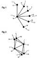
- Fig. 1 schematically depicts a physical communication network structure with a plurality of autonomous communication networks, i.e. a Gold Command network 1 with a Gold Command network node 10, a COBR (Cabinet Office Briefing Room) network 2 with a COBR network node 20, a Special Forces network 3 with a Special Forces network node 30, a Fire Service network 4 with a Fire Service network node 40, an Environmental Agency network 5 with an Environmental Agency network node 50 and a police network 6 with a police network node 60.
- Each one of said nodes 10, 20, 30, 40, 50, 60 of these communication networks 1, 2, 3, 4, 5, 6 is connected to a router 70 provided in a common gateway 7.
- a computer (not shown) is provided in said gateway 7 to control said router 70 by means of a computer program running on said computer.
- the computer program can be operated locally at the gateway or remotely via a secure connection by authenticated and authorised operators.
- the router 70 can be configured, e.g. by the computer program, to interconnect two or more of the autonomous networks 1, 2, 3, 4, 5, 6 physically connected to the router 70.
- Autonomous networks interconnected in this way form a logical network shown in Fig. 2 .
- the connecting lines between the nodes 10, 20, 30, 40, 50, 60 shown in Fig. 2 depict the respective interconnection between the networks associated to the respective nodes.
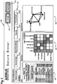
- the screenshot of the graphic user interface in Fig. 3 shows the controls for:
- the representation in the 'Grid View' indicates by the dark fields marked with a cross impossible connections of each network with itself.
- the dark fields without a cross indicate selected interconnections which are shown in the 'Logical Network' section 130.
- the remaining white fields represent possible connections which are not selected in the shown example.
- a user may - if a requested preset configuration is not available - manually select one or more network interconnection(s) by selecting networks to be connected from a list in the 'Links' section or by clicking on one or more field(s) in the 'Grid View' matrix and the interconnection(s) will be activated/de-activated by subsequently clicking on the 'Activate' or 'Deactivate' button, respectively.
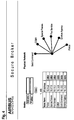
- the screenshot of the graphic user interface in Fig 4 shows the controls for defining the nodes and a representation of the physical network with the nodes connected to the gateway. This user interface would be used as part of the system initialisation and for maintenance processes.
- the invention provides a computer program based solution that implements the technical processes of:
- a new logical network is formed by interconnecting physical networks in a much more rapid timescale by a business end user. This is achieved through the following process steps:
- the network structure and the method of the present invention may be applied to a broad variety of scenarios of which the following scenarios are given as examples.
- a set of government agency networks are physically linked via a gateway that in normal situations is deactivated.
- the gateway can be activated by the software program of the invention in a configuration shown in Fig 2 and Fig. 3 selecting e.g. the Cabinet Office Briefing Room (COBR) connected to a Gold Command which is connected to police, Fire Service, and Environment Agency.
- COBR Cabinet Office Briefing Room
- the gateway can be deactivated to return to the default state. In the software this would involve the user selecting the pre-planned configuration and selecting 'Activate', and at the end of the emergency situation selecting 'Deactivate'.
- the system managing network access for the police force could allow an authorized user of the police forces to remove all access from the compromised police station instantly from their central command post. In the software this would involve the user selecting the compromised police station within the police communication network, selecting 'Disconnect from All' and selecting 'Activate'.
- Seamen on board a ship are provided network access via 3G hubs in their areas of the vessel primarily for internet access. At times when bandwidth is limited and is required for higher priority operational needs this system could be used to virtually disconnect the individual hubs as required, and reconnect when appropriate.
Landscapes
- Engineering & Computer Science (AREA)
- Computer Networks & Wireless Communication (AREA)
- Signal Processing (AREA)
- Computer Security & Cryptography (AREA)
- Computer Hardware Design (AREA)
- Computing Systems (AREA)
- General Engineering & Computer Science (AREA)
- Human Computer Interaction (AREA)
- Data Exchanges In Wide-Area Networks (AREA)
Description
- The present invention is directed to a communication network structure, in particular to a data communication network structure. It is further directed to a method of interconnecting autonomous communication networks, in particular autonomous data communication networks. The invention is further directed to a computer software implementing such a method.
- Communication networks, in particular data communication networks, are in use in nearly every organisation or company. Usually, these autonomous networks are closed units interconnecting only members to this organisation or company.
- However, there may be situations in which it is desired or even needed to interconnect two or more of these autonomous communication networks. The prior art in such a situation is that network specialists manually interconnect these autonomous networks - a work which requires special information technology skills and tools and which is time consuming. In urgent scenarios like emergency management scenarios neither these network specialists nor the necessary time are available. Such scenarios are for example unplanned situations necessitating an immediate response, like natural disasters (e.g. wildfires, flooding, earthquakes), man made disasters (e.g. industrial accidents, chemical plant accidents or nuclear plant accidents), major traffic accidents (e.g. airplane crashes, railroad accidents, like train derailments, or naval vessel collisions), riots or terrorist attacks etc. In these situations it may be necessary to quickly interconnect communication networks of a plurality of organisations like the police forces, fire fighters, national or regional civil protection units, medical rescue and support organisations, government agencies or even military forces.
- It would thus be helpful if the users participating in such a scenario had the ability to control access to their own network and to the networks of other participating organisations instantly. This requires that:
- a. the control can be achieved without the need to involve technical specialists e.g. network engineers to apply a reconfiguration to network equipment or network planner using a traditional network management system;
- b. it must be easy and intuitive enough for a non-technical user to operate;
- c. the desired effect can be achieved very rapidly i.e. from less than three user interactions e.g. mouse clicks and without having to reference other information e.g. look up addresses.
-
US 2010/246443 A1 discloses techniques for providing logical networking functionality for managed computer networks, such as for virtual computer networks provided on behalf of users or other entities. In some situations, a user may configure or otherwise specify a network topology for a virtual computer network, such as a logical network topology that separates multiple computing nodes of the virtual computer network into multiple logical sub-networks and/or that specifies one or more logical networking devices for the virtual computer network. After a network topology is specified for a virtual computer network, logical networking functionality corresponding to the network topology may be provided in various manners, such as without physically implementing the network topology for the virtual computer network. In some situations, the computing nodes may include virtual machine nodes hosted on one or more physical computing machines or systems, such as by or on behalf of one or more users. - The object of the present invention is to provide a communication network system as claimed in
claim 1, and a method of interconnecting autonomous communication networks as claimed in claim 3, as well as a computer program, as claimed inclaim 4, implementing such a method enabling a user to quickly and instantly interconnect autonomous communication networks without the need of special information technology skills. - The present invention is defined by the independent claims. Preferred embodiments are defined by the dependent claims.
- According to an object of the invention, the communication network system according to
claim 1 is a data communication network structure. It comprises a plurality of autonomous data communication networks, wherein each autonomous data communication network comprises at least one network node, wherein said at least one node of each communication network is connected or connectable to a common gateway and wherein said common gateway is designed to selectively connect at least two of said nodes in order to provide intercommunication ability between the related communication networks. Said gateway is designed to allow a user to individually select and interconnect two or more network nodes from said plurality of autonomous data communication networks. - In a preferred embodiment of the data communication network structure according to the invention said gateway is designed to have a plurality of predefined and preset configurations of inter-node connections and to allow the user to directly select and activate a preset configuration from said plurality of predefined and preset configurations.
- It is also advantageous when said common gateway comprises at least one router element to which said nodes of said autonomous data communication networks are selectively connected or connectable. Another object of the invention is a method as claimed in claim 3.
- According to another object of the invention, the above method is implemented in a computer program, as claimed in
claim 4, which is running on a computer provided in said communication network structure, i.e. in said gateway. - The basic idea of the invention is to provide a gateway between the autonomous communication networks potentially to be interconnected and to provide a method, e.g. implemented in a computer program, enabling a user to quickly and instantly activate an interconnection between selected ones of said autonomous networks. The preferred solution is to offer to the user a graphic user interface on a computer display on which the user can establish the desired connections by one or more selection clicks (selecting one or more networks to be interconnected) and by one activation click activating the interconnection(s). The same procedure can be carried out for de-activating the connection(s) to one or more of said autonomous communication networks by selecting the network(s) to be disconnected and by a subsequent de-activation click.
- Although the networks shown, described and defined in this document have a node, the invention is not delimited to networks of star topology. The invention may also be applied to other network topologies, e.g. ring topologies or bus topologies, having a dedicated node.
- The invention is hereinafter described by example with reference to the drawings. In these drawings
- Fig. 1
- shows a physical communication network structure according to the invention;
- Fig. 2
- shows a logical network established according to the method of the invention;
- Fig. 3
- shows a screenshot of a graphic user interface of the computer program of the invention and
- Fig. 4
- shows another screenshot of a graphic user interface of the computer program of the invention.
-
Fig. 1 schematically depicts a physical communication network structure with a plurality of autonomous communication networks, i.e. a Gold Commandnetwork 1 with a Gold Commandnetwork node 10, a COBR (Cabinet Office Briefing Room)network 2 with aCOBR network node 20, a Special Forces network 3 with a Special Forcesnetwork node 30, a FireService network 4 with a Fire Servicenetwork node 40, an Environmental Agencynetwork 5 with an Environmental Agencynetwork node 50 and aPolice network 6 with aPolice network node 60. Each one of saidnodes communication networks router 70 provided in acommon gateway 7. - A computer (not shown) is provided in said
gateway 7 to control saidrouter 70 by means of a computer program running on said computer. The computer program can be operated locally at the gateway or remotely via a secure connection by authenticated and authorised operators. - The
router 70 can be configured, e.g. by the computer program, to interconnect two or more of theautonomous networks router 70. Autonomous networks interconnected in this way form a logical network shown inFig. 2 . The connecting lines between thenodes Fig. 2 depict the respective interconnection between the networks associated to the respective nodes. - The screenshot of the graphic user interface in
Fig. 3 shows the controls for: - A. Creating a set of links in the 'Links'
section 100; - B. Selecting presets and saving links as
presets section 110; - C. Representations of the network in a 'Grid View'
section 120 and in a 'Logical Network'section 130 - D. Activation and
deactivation buttons header 140. - The representation in the 'Grid View' indicates by the dark fields marked with a cross impossible connections of each network with itself. The dark fields without a cross indicate selected interconnections which are shown in the 'Logical Network'
section 130. The remaining white fields represent possible connections which are not selected in the shown example. - A user may - if a requested preset configuration is not available - manually select one or more network interconnection(s) by selecting networks to be connected from a list in the 'Links' section or by clicking on one or more field(s) in the 'Grid View' matrix and the interconnection(s) will be activated/de-activated by subsequently clicking on the 'Activate' or 'Deactivate' button, respectively.
- The screenshot of the graphic user interface in
Fig 4 shows the controls for defining the nodes and a representation of the physical network with the nodes connected to the gateway. This user interface would be used as part of the system initialisation and for maintenance processes. - The invention provides a computer program based solution that implements the technical processes of:
- controlling and applying access lists on baseband router elements based on a logical network defined by the end user;
- defining preset logical network configurations for immediate activation of pre-planned network interconnections;
- activation of ad-hoc configurations;
- deactivation preventing any connections across the managed network structure;
- for a given node connecting to and disconnecting from all other nodes;
- creating or removing individual links between the nodes.
- According to the invention a new logical network is formed by interconnecting physical networks in a much more rapid timescale by a business end user. This is achieved through the following process steps:
- defining links between nodes either by selecting a preset configuration or ad-hoc selection;
- presenting a representation of the logical network to the user in a variety of formats (listing table of interconnected or interconnectable networks, grid table of possible interconnections or logical network representation);
- selecting an 'Activate' button by the user;
- creating by the software an access-list based on the set of links using the IP addresses defined for each node e.g. for a link between node with IP address 10.1.2.2 and node with IP address 10.1.3.2 by a command "permit ip host 10.1.2.2 host 10.1.3.2";
- connecting to the baseband element e.g. to the router;
- applying the access list on the router as the new configuration;
- activating the new logical network;
- reporting the result to the user.
- The network structure and the method of the present invention may be applied to a broad variety of scenarios of which the following scenarios are given as examples.
- A set of government agency networks are physically linked via a gateway that in normal situations is deactivated. In the case of emergency, e.g. natural disaster, the gateway can be activated by the software program of the invention in a configuration shown in
Fig 2 andFig. 3 selecting e.g. the Cabinet Office Briefing Room (COBR) connected to a Gold Command which is connected to Police, Fire Service, and Environment Agency. When the crisis is passed the gateway can be deactivated to return to the default state. In the software this would involve the user selecting the pre-planned configuration and selecting 'Activate', and at the end of the emergency situation selecting 'Deactivate'. - If, for example, a police station was overrun by external forces, terrorists or riots and is thus compromised, the system managing network access for the police force could allow an authorized user of the police forces to remove all access from the compromised police station instantly from their central command post. In the software this would involve the user selecting the compromised police station within the police communication network, selecting 'Disconnect from All' and selecting 'Activate'.
- Seamen on board a ship are provided network access via 3G hubs in their areas of the vessel primarily for internet access. At times when bandwidth is limited and is required for higher priority operational needs this system could be used to virtually disconnect the individual hubs as required, and reconnect when appropriate.
- Reference numerals in the claims, in the description and in the drawings are provided only for a better understanding of the invention and shall not delimit the scope of protection which is defined by the wording and meaning of the claims.
Claims (4)
- Data communication network system comprising a plurality of autonomous data communication networks (1, 2, 3, 4, 5, 6), and a common gateway,
wherein each autonomous data communication network (1, 2, 3, 4, 5, 6) comprises at least one network node (10, 20, 30, 40, 50, 60),
wherein said at least one node (10, 20, 30, 40, 50, 60) of each communication network (1, 2, 3, 4, 5, 6) is connected or connectable to the common gateway (7) wherein said common gateway (7) is designed to selectively connect at least two of said nodes (10, 20, 30, 40, 50, 60) in order to provide intercommunication ability between the related autonomous communication networks (1, 2, 3, 4, 5, 6),
wherein said common gateway (7) comprises at least one router element (70) to which said nodes of said autonomous communication networks are selectively connected or connectable, wherein a computer is provided in said gateway to control said router element by means of a computer program running on said computer, the computer program being operable locally at the gateway or remotely via a secure connection by an authenticated and authorised user,
wherein said gateway (7) is designed to allow the user, by offering to the user a graphic user interface on a computer display, to individually select and interconnect two or more network nodes from said plurality of autonomous data communication networks (1, 2, 3, 4, 5, 6). - Data communication network structure according to claim 1,
wherein said gateway (7) is designed to have a plurality of predefined and preset configurations of inter-node connections and to allow the user to directly select and activate a preset configuration from said plurality of predefined and preset configurations. - A method of interconnecting autonomous data communication networks, each communication network having at least one network node connected or connectable to a common gateway, wherein the method comprises the steps of- selecting networks or network nodes to be interconnected from a group or a list of available networks or network nodes or selecting a preset configuration of inter-node connections;- activating an interconnection between the selected networks or network nodes by creating an access-list using the IP-addresses defined for each node;- applying the access-list on a router element provided in said common gateway, thus connecting the nodes/networks to each other; and- selecting and interconnecting, by a user, two or more network nodes from the communication networks, wherein said common gateway comprises at least one router element to which said nodes of said autonomous data communication networks are selectively connected or connectable, wherein a computer is provided in said gateway to control said router element by means of a computer program running on said computer, the computer program being operable locally at the gateway or remotely via a secure connection by an authenticated and authorised user, wherein said gateway is designed to allow the user, by offering to the user a graphic user interface on a computer display, to individually select and interconnect two or more network nodes from the autonomous data communication networks.
- Computer program implementing the method of claim 3, which, when run on a computer provided in said gateway, causes the computer to perform the steps of method claim 3.
Priority Applications (3)
| Application Number | Priority Date | Filing Date | Title |
|---|---|---|---|
| EP14002102.3A EP2958267B1 (en) | 2014-06-18 | 2014-06-18 | Communication network structure, method of interconnecting autonomous communication networks and computer program implementing said method |
| ES14002102T ES2748169T3 (en) | 2014-06-18 | 2014-06-18 | Communication network structure, method of interconnection of autonomous communication networks and computer program that implements said method |
| US14/741,766 US10148663B2 (en) | 2014-06-18 | 2015-06-17 | Communication network structure, method of interconnecting autonomous communication networks and computer program implementing said method |
Applications Claiming Priority (1)
| Application Number | Priority Date | Filing Date | Title |
|---|---|---|---|
| EP14002102.3A EP2958267B1 (en) | 2014-06-18 | 2014-06-18 | Communication network structure, method of interconnecting autonomous communication networks and computer program implementing said method |
Publications (2)
| Publication Number | Publication Date |
|---|---|
| EP2958267A1 EP2958267A1 (en) | 2015-12-23 |
| EP2958267B1 true EP2958267B1 (en) | 2019-09-04 |
Family
ID=51062611
Family Applications (1)
| Application Number | Title | Priority Date | Filing Date |
|---|---|---|---|
| EP14002102.3A Active EP2958267B1 (en) | 2014-06-18 | 2014-06-18 | Communication network structure, method of interconnecting autonomous communication networks and computer program implementing said method |
Country Status (3)
| Country | Link |
|---|---|
| US (1) | US10148663B2 (en) |
| EP (1) | EP2958267B1 (en) |
| ES (1) | ES2748169T3 (en) |
Family Cites Families (16)
| Publication number | Priority date | Publication date | Assignee | Title |
|---|---|---|---|---|
| US6690675B1 (en) * | 1999-12-30 | 2004-02-10 | At&T Corp. | User programmable fail-proof IP hotline/warm-line |
| JP2002152279A (en) * | 2000-11-10 | 2002-05-24 | Sony Corp | Network connection control apparatus and method |
| US20030079032A1 (en) * | 2001-09-10 | 2003-04-24 | John Orsolits | Enterprise software gateway |
| EP1780943A1 (en) * | 2005-10-31 | 2007-05-02 | Hewlett-Packard Development Company, L.P. | Discovery of ISO Layer-2 Topology |
| US8341298B2 (en) * | 2005-12-02 | 2012-12-25 | The Boeing Company | Scalable on-board open data network architecture |
| US20070280203A1 (en) * | 2006-06-02 | 2007-12-06 | Shmuel Shaffer | Method and System for Managing a Plurality of Virtual Talk Groups |
| US7974650B2 (en) * | 2007-02-20 | 2011-07-05 | Alcatel-Lucent Usa Inc. | Interoperability between different types of wireless networks for push to talk group calls |
| US9774746B1 (en) * | 2007-04-03 | 2017-09-26 | At&T Mobility Ii Llc | Advanced conference call controls |
| US9379909B2 (en) * | 2007-06-29 | 2016-06-28 | Blackberry Limited | Method and system for managing enterprise-related mobile calls |
| US8634815B2 (en) * | 2008-05-22 | 2014-01-21 | Verizon Patent And Licensing Inc. | System and method for reflecting information from participants |
| US9106540B2 (en) * | 2009-03-30 | 2015-08-11 | Amazon Technologies, Inc. | Providing logical networking functionality for managed computer networks |
| US9379946B2 (en) * | 2009-11-12 | 2016-06-28 | Microsoft Technology Licensing, Llc | Model-based virtual networking |
| US8406798B2 (en) * | 2009-12-22 | 2013-03-26 | Motorola Solutions, Inc. | Method and apparatus for bridging calls between two disparate push-to-talk systems |
| KR101566577B1 (en) * | 2010-01-06 | 2015-11-05 | 인터디지탈 패튼 홀딩스, 인크 | Method and apparatus for assisted/coordinated intra-home communications |
| US9191416B2 (en) * | 2010-04-16 | 2015-11-17 | Damaka, Inc. | System and method for providing enterprise voice call continuity |
| US9036647B2 (en) * | 2012-12-27 | 2015-05-19 | Alcatel Lucent | Method and apparatus for network security |
-
2014
- 2014-06-18 EP EP14002102.3A patent/EP2958267B1/en active Active
- 2014-06-18 ES ES14002102T patent/ES2748169T3/en active Active
-
2015
- 2015-06-17 US US14/741,766 patent/US10148663B2/en active Active
Non-Patent Citations (1)
| Title |
|---|
| None * |
Also Published As
| Publication number | Publication date |
|---|---|
| EP2958267A1 (en) | 2015-12-23 |
| US20150373025A1 (en) | 2015-12-24 |
| ES2748169T3 (en) | 2020-03-13 |
| US10148663B2 (en) | 2018-12-04 |
Similar Documents
| Publication | Publication Date | Title |
|---|---|---|
| Ramesh et al. | The smart network management automation algorithm for administration of reliable 5G communication networks | |
| US10476912B2 (en) | Creating, visualizing, and simulating a threat based whitelisting security policy and security zones for networks | |
| US12021683B2 (en) | Fabric-based virtual air gap provisioning, system and methods | |
| US10316623B2 (en) | Method and system for controlling well operations | |
| CN106330575A (en) | Safety service platform and safety service deployment method | |
| CN103973560A (en) | Device and method for fault treatment of stack links in IRF (intelligent resilient framework) system | |
| Ibarra et al. | Benefits brought by the use of OpenFlow/SDN on the AmLight intercontinental research and education network | |
| USRE46770E1 (en) | Computer managing method | |
| CN104238496B (en) | For measuring and reporting the internuncial device and method of redundant wireless with the time | |
| CN102033616A (en) | Sharing and mutual-backup system for multi-system terminal computer host | |
| EP2958267B1 (en) | Communication network structure, method of interconnecting autonomous communication networks and computer program implementing said method | |
| Li et al. | Enhanced robustness of control network for Chinese train control system level-3 (CTCS-3) facilitated by software-defined networking architecture | |
| Denning | Hastily Formed Networks: Collaboration in the Absence of Authority. | |
| Lu et al. | Research on the technology of power unified cloud management platform | |
| Dugdale et al. | Engineering effective cooperation and communication: a bottom-up approach | |
| CN104935450A (en) | Access session management method and device | |
| Bordetsky et al. | Network aware tactical collaborative environments | |
| JP6418316B2 (en) | Communication equipment setting device | |
| Luiijf et al. | Assessing and improving SCADA security in the Dutch drinking water sector | |
| US9448548B2 (en) | Synchronizing and displaying fault tolerant Ethernet (FTE) status | |
| CN201876825U (en) | Sharing and mutually backing-up system for multiple system terminal main frames | |
| Nagatomo et al. | An AR-based VLAN visualizer | |
| Kuczyński et al. | Versatile remote access environment for computer networking laboratory | |
| Kálmán | Security implications of software defined networking in industrial control systems | |
| Joshi et al. | Nimble Troubleshooting and Firewall Configuration |
Legal Events
| Date | Code | Title | Description |
|---|---|---|---|
| PUAI | Public reference made under article 153(3) epc to a published international application that has entered the european phase |
Free format text: ORIGINAL CODE: 0009012 |
|
| AK | Designated contracting states |
Kind code of ref document: A1 Designated state(s): AL AT BE BG CH CY CZ DE DK EE ES FI FR GB GR HR HU IE IS IT LI LT LU LV MC MK MT NL NO PL PT RO RS SE SI SK SM TR |
|
| AX | Request for extension of the european patent |
Extension state: BA ME |
|
| RAP1 | Party data changed (applicant data changed or rights of an application transferred) |
Owner name: AIRBUS DEFENCE AND SPACE LIMITED |
|
| 17P | Request for examination filed |
Effective date: 20160623 |
|
| STAA | Information on the status of an ep patent application or granted ep patent |
Free format text: STATUS: EXAMINATION IS IN PROGRESS |
|
| 17Q | First examination report despatched |
Effective date: 20180424 |
|
| GRAP | Despatch of communication of intention to grant a patent |
Free format text: ORIGINAL CODE: EPIDOSNIGR1 |
|
| STAA | Information on the status of an ep patent application or granted ep patent |
Free format text: STATUS: GRANT OF PATENT IS INTENDED |
|
| INTG | Intention to grant announced |
Effective date: 20190328 |
|
| GRAS | Grant fee paid |
Free format text: ORIGINAL CODE: EPIDOSNIGR3 |
|
| GRAA | (expected) grant |
Free format text: ORIGINAL CODE: 0009210 |
|
| STAA | Information on the status of an ep patent application or granted ep patent |
Free format text: STATUS: THE PATENT HAS BEEN GRANTED |
|
| AK | Designated contracting states |
Kind code of ref document: B1 Designated state(s): AL AT BE BG CH CY CZ DE DK EE ES FI FR GB GR HR HU IE IS IT LI LT LU LV MC MK MT NL NO PL PT RO RS SE SI SK SM TR |
|
| REG | Reference to a national code |
Ref country code: GB Ref legal event code: FG4D |
|
| REG | Reference to a national code |
Ref country code: CH Ref legal event code: EP |
|
| REG | Reference to a national code |
Ref country code: AT Ref legal event code: REF Ref document number: 1176905 Country of ref document: AT Kind code of ref document: T Effective date: 20190915 |
|
| REG | Reference to a national code |
Ref country code: DE Ref legal event code: R096 Ref document number: 602014052812 Country of ref document: DE |
|
| REG | Reference to a national code |
Ref country code: IE Ref legal event code: FG4D |
|
| REG | Reference to a national code |
Ref country code: NL Ref legal event code: MP Effective date: 20190904 |
|
| REG | Reference to a national code |
Ref country code: LT Ref legal event code: MG4D |
|
| PG25 | Lapsed in a contracting state [announced via postgrant information from national office to epo] |
Ref country code: FI Free format text: LAPSE BECAUSE OF FAILURE TO SUBMIT A TRANSLATION OF THE DESCRIPTION OR TO PAY THE FEE WITHIN THE PRESCRIBED TIME-LIMIT Effective date: 20190904 Ref country code: LT Free format text: LAPSE BECAUSE OF FAILURE TO SUBMIT A TRANSLATION OF THE DESCRIPTION OR TO PAY THE FEE WITHIN THE PRESCRIBED TIME-LIMIT Effective date: 20190904 Ref country code: HR Free format text: LAPSE BECAUSE OF FAILURE TO SUBMIT A TRANSLATION OF THE DESCRIPTION OR TO PAY THE FEE WITHIN THE PRESCRIBED TIME-LIMIT Effective date: 20190904 Ref country code: BG Free format text: LAPSE BECAUSE OF FAILURE TO SUBMIT A TRANSLATION OF THE DESCRIPTION OR TO PAY THE FEE WITHIN THE PRESCRIBED TIME-LIMIT Effective date: 20191204 Ref country code: NO Free format text: LAPSE BECAUSE OF FAILURE TO SUBMIT A TRANSLATION OF THE DESCRIPTION OR TO PAY THE FEE WITHIN THE PRESCRIBED TIME-LIMIT Effective date: 20191204 Ref country code: SE Free format text: LAPSE BECAUSE OF FAILURE TO SUBMIT A TRANSLATION OF THE DESCRIPTION OR TO PAY THE FEE WITHIN THE PRESCRIBED TIME-LIMIT Effective date: 20190904 |
|
| PG25 | Lapsed in a contracting state [announced via postgrant information from national office to epo] |
Ref country code: RS Free format text: LAPSE BECAUSE OF FAILURE TO SUBMIT A TRANSLATION OF THE DESCRIPTION OR TO PAY THE FEE WITHIN THE PRESCRIBED TIME-LIMIT Effective date: 20190904 Ref country code: GR Free format text: LAPSE BECAUSE OF FAILURE TO SUBMIT A TRANSLATION OF THE DESCRIPTION OR TO PAY THE FEE WITHIN THE PRESCRIBED TIME-LIMIT Effective date: 20191205 Ref country code: AL Free format text: LAPSE BECAUSE OF FAILURE TO SUBMIT A TRANSLATION OF THE DESCRIPTION OR TO PAY THE FEE WITHIN THE PRESCRIBED TIME-LIMIT Effective date: 20190904 Ref country code: LV Free format text: LAPSE BECAUSE OF FAILURE TO SUBMIT A TRANSLATION OF THE DESCRIPTION OR TO PAY THE FEE WITHIN THE PRESCRIBED TIME-LIMIT Effective date: 20190904 |
|
| REG | Reference to a national code |
Ref country code: ES Ref legal event code: FG2A Ref document number: 2748169 Country of ref document: ES Kind code of ref document: T3 Effective date: 20200313 |
|
| REG | Reference to a national code |
Ref country code: AT Ref legal event code: MK05 Ref document number: 1176905 Country of ref document: AT Kind code of ref document: T Effective date: 20190904 |
|
| PG25 | Lapsed in a contracting state [announced via postgrant information from national office to epo] |
Ref country code: EE Free format text: LAPSE BECAUSE OF FAILURE TO SUBMIT A TRANSLATION OF THE DESCRIPTION OR TO PAY THE FEE WITHIN THE PRESCRIBED TIME-LIMIT Effective date: 20190904 Ref country code: PL Free format text: LAPSE BECAUSE OF FAILURE TO SUBMIT A TRANSLATION OF THE DESCRIPTION OR TO PAY THE FEE WITHIN THE PRESCRIBED TIME-LIMIT Effective date: 20190904 Ref country code: NL Free format text: LAPSE BECAUSE OF FAILURE TO SUBMIT A TRANSLATION OF THE DESCRIPTION OR TO PAY THE FEE WITHIN THE PRESCRIBED TIME-LIMIT Effective date: 20190904 Ref country code: AT Free format text: LAPSE BECAUSE OF FAILURE TO SUBMIT A TRANSLATION OF THE DESCRIPTION OR TO PAY THE FEE WITHIN THE PRESCRIBED TIME-LIMIT Effective date: 20190904 Ref country code: RO Free format text: LAPSE BECAUSE OF FAILURE TO SUBMIT A TRANSLATION OF THE DESCRIPTION OR TO PAY THE FEE WITHIN THE PRESCRIBED TIME-LIMIT Effective date: 20190904 Ref country code: PT Free format text: LAPSE BECAUSE OF FAILURE TO SUBMIT A TRANSLATION OF THE DESCRIPTION OR TO PAY THE FEE WITHIN THE PRESCRIBED TIME-LIMIT Effective date: 20200106 |
|
| PG25 | Lapsed in a contracting state [announced via postgrant information from national office to epo] |
Ref country code: SK Free format text: LAPSE BECAUSE OF FAILURE TO SUBMIT A TRANSLATION OF THE DESCRIPTION OR TO PAY THE FEE WITHIN THE PRESCRIBED TIME-LIMIT Effective date: 20190904 Ref country code: CZ Free format text: LAPSE BECAUSE OF FAILURE TO SUBMIT A TRANSLATION OF THE DESCRIPTION OR TO PAY THE FEE WITHIN THE PRESCRIBED TIME-LIMIT Effective date: 20190904 Ref country code: IS Free format text: LAPSE BECAUSE OF FAILURE TO SUBMIT A TRANSLATION OF THE DESCRIPTION OR TO PAY THE FEE WITHIN THE PRESCRIBED TIME-LIMIT Effective date: 20200224 Ref country code: SM Free format text: LAPSE BECAUSE OF FAILURE TO SUBMIT A TRANSLATION OF THE DESCRIPTION OR TO PAY THE FEE WITHIN THE PRESCRIBED TIME-LIMIT Effective date: 20190904 |
|
| REG | Reference to a national code |
Ref country code: DE Ref legal event code: R097 Ref document number: 602014052812 Country of ref document: DE |
|
| PLBE | No opposition filed within time limit |
Free format text: ORIGINAL CODE: 0009261 |
|
| STAA | Information on the status of an ep patent application or granted ep patent |
Free format text: STATUS: NO OPPOSITION FILED WITHIN TIME LIMIT |
|
| PG2D | Information on lapse in contracting state deleted |
Ref country code: IS |
|
| PG25 | Lapsed in a contracting state [announced via postgrant information from national office to epo] |
Ref country code: DK Free format text: LAPSE BECAUSE OF FAILURE TO SUBMIT A TRANSLATION OF THE DESCRIPTION OR TO PAY THE FEE WITHIN THE PRESCRIBED TIME-LIMIT Effective date: 20190904 Ref country code: IS Free format text: LAPSE BECAUSE OF FAILURE TO SUBMIT A TRANSLATION OF THE DESCRIPTION OR TO PAY THE FEE WITHIN THE PRESCRIBED TIME-LIMIT Effective date: 20200105 |
|
| 26N | No opposition filed |
Effective date: 20200605 |
|
| PG25 | Lapsed in a contracting state [announced via postgrant information from national office to epo] |
Ref country code: SI Free format text: LAPSE BECAUSE OF FAILURE TO SUBMIT A TRANSLATION OF THE DESCRIPTION OR TO PAY THE FEE WITHIN THE PRESCRIBED TIME-LIMIT Effective date: 20190904 |
|
| PG25 | Lapsed in a contracting state [announced via postgrant information from national office to epo] |
Ref country code: MC Free format text: LAPSE BECAUSE OF FAILURE TO SUBMIT A TRANSLATION OF THE DESCRIPTION OR TO PAY THE FEE WITHIN THE PRESCRIBED TIME-LIMIT Effective date: 20190904 |
|
| REG | Reference to a national code |
Ref country code: CH Ref legal event code: PL |
|
| PG25 | Lapsed in a contracting state [announced via postgrant information from national office to epo] |
Ref country code: LU Free format text: LAPSE BECAUSE OF NON-PAYMENT OF DUE FEES Effective date: 20200618 |
|
| REG | Reference to a national code |
Ref country code: BE Ref legal event code: MM Effective date: 20200630 |
|
| PG25 | Lapsed in a contracting state [announced via postgrant information from national office to epo] |
Ref country code: IE Free format text: LAPSE BECAUSE OF NON-PAYMENT OF DUE FEES Effective date: 20200618 Ref country code: LI Free format text: LAPSE BECAUSE OF NON-PAYMENT OF DUE FEES Effective date: 20200630 Ref country code: CH Free format text: LAPSE BECAUSE OF NON-PAYMENT OF DUE FEES Effective date: 20200630 |
|
| PG25 | Lapsed in a contracting state [announced via postgrant information from national office to epo] |
Ref country code: BE Free format text: LAPSE BECAUSE OF NON-PAYMENT OF DUE FEES Effective date: 20200630 |
|
| REG | Reference to a national code |
Ref country code: DE Ref legal event code: R079 Ref document number: 602014052812 Country of ref document: DE Free format text: PREVIOUS MAIN CLASS: H04L0012240000 Ipc: H04L0041000000 |
|
| PG25 | Lapsed in a contracting state [announced via postgrant information from national office to epo] |
Ref country code: TR Free format text: LAPSE BECAUSE OF FAILURE TO SUBMIT A TRANSLATION OF THE DESCRIPTION OR TO PAY THE FEE WITHIN THE PRESCRIBED TIME-LIMIT Effective date: 20190904 Ref country code: MT Free format text: LAPSE BECAUSE OF FAILURE TO SUBMIT A TRANSLATION OF THE DESCRIPTION OR TO PAY THE FEE WITHIN THE PRESCRIBED TIME-LIMIT Effective date: 20190904 Ref country code: CY Free format text: LAPSE BECAUSE OF FAILURE TO SUBMIT A TRANSLATION OF THE DESCRIPTION OR TO PAY THE FEE WITHIN THE PRESCRIBED TIME-LIMIT Effective date: 20190904 |
|
| PG25 | Lapsed in a contracting state [announced via postgrant information from national office to epo] |
Ref country code: MK Free format text: LAPSE BECAUSE OF FAILURE TO SUBMIT A TRANSLATION OF THE DESCRIPTION OR TO PAY THE FEE WITHIN THE PRESCRIBED TIME-LIMIT Effective date: 20190904 |
|
| PGFP | Annual fee paid to national office [announced via postgrant information from national office to epo] |
Ref country code: DE Payment date: 20250520 Year of fee payment: 12 |
|
| PGFP | Annual fee paid to national office [announced via postgrant information from national office to epo] |
Ref country code: GB Payment date: 20250520 Year of fee payment: 12 |
|
| PGFP | Annual fee paid to national office [announced via postgrant information from national office to epo] |
Ref country code: IT Payment date: 20250520 Year of fee payment: 12 |
|
| PGFP | Annual fee paid to national office [announced via postgrant information from national office to epo] |
Ref country code: FR Payment date: 20250520 Year of fee payment: 12 |
|
| PGFP | Annual fee paid to national office [announced via postgrant information from national office to epo] |
Ref country code: ES Payment date: 20250701 Year of fee payment: 12 |