EP2940923B1 - Method and device for optics based quantum random number generator - Google Patents
Method and device for optics based quantum random number generator Download PDFInfo
- Publication number
- EP2940923B1 EP2940923B1 EP14166272.6A EP14166272A EP2940923B1 EP 2940923 B1 EP2940923 B1 EP 2940923B1 EP 14166272 A EP14166272 A EP 14166272A EP 2940923 B1 EP2940923 B1 EP 2940923B1
- Authority
- EP
- European Patent Office
- Prior art keywords
- detector
- fact
- photon
- light source
- quantum
- Prior art date
- Legal status (The legal status is an assumption and is not a legal conclusion. Google has not performed a legal analysis and makes no representation as to the accuracy of the status listed.)
- Active
Links
Images


Classifications
-
- G—PHYSICS
- G06—COMPUTING OR CALCULATING; COUNTING
- G06F—ELECTRIC DIGITAL DATA PROCESSING
- G06F7/00—Methods or arrangements for processing data by operating upon the order or content of the data handled
- G06F7/58—Random or pseudo-random number generators
- G06F7/588—Random number generators, i.e. based on natural stochastic processes
-
- G—PHYSICS
- G06—COMPUTING OR CALCULATING; COUNTING
- G06F—ELECTRIC DIGITAL DATA PROCESSING
- G06F17/00—Digital computing or data processing equipment or methods, specially adapted for specific functions
- G06F17/10—Complex mathematical operations
- G06F17/16—Matrix or vector computation, e.g. matrix-matrix or matrix-vector multiplication, matrix factorization
-
- H—ELECTRICITY
- H04—ELECTRIC COMMUNICATION TECHNIQUE
- H04L—TRANSMISSION OF DIGITAL INFORMATION, e.g. TELEGRAPHIC COMMUNICATION
- H04L9/00—Cryptographic mechanisms or cryptographic arrangements for secret or secure communications; Network security protocols
- H04L9/08—Key distribution or management, e.g. generation, sharing or updating, of cryptographic keys or passwords
- H04L9/0816—Key establishment, i.e. cryptographic processes or cryptographic protocols whereby a shared secret becomes available to two or more parties, for subsequent use
- H04L9/0852—Quantum cryptography
-
- G—PHYSICS
- G06—COMPUTING OR CALCULATING; COUNTING
- G06F—ELECTRIC DIGITAL DATA PROCESSING
- G06F2207/00—Indexing scheme relating to methods or arrangements for processing data by operating upon the order or content of the data handled
- G06F2207/58—Indexing scheme relating to groups G06F7/58 - G06F7/588
Definitions
- the present invention pertains to a device for quantum random number generation based on an optical process of quantum nature comprising a light source emitting photons randomly as well as to a corresponding method, both allowing to obtain random numbers of high quality.
- the present invention is situated in the context of the generation of random numbers.
- the generation of high quality random numbers is essential to security of many applications such as cryptographic protocols, both classical and quantum.
- conventional asymmetric key protocols like the well known DSA-, RSA- and Diffie-Hellman-algorithms, use random numbers, tested for primality, to generate their keys.
- Another example is the unconditionally secure one-time pad protocol which needs a string of perfectly random numbers of a length equal to that of the data to be encrypted.
- the main limitation of this protocol is the requirement for key exchange.
- Quantum key distribution offers a way to generate two secure keys at distant locations, but its implementation also requires a vast quantity of random numbers. All these examples reflect Kerckhoffs' principle which dates back to the 19 th century and states that the security of a cypher must reside entirely in the key.
- QRNGs quantum random number generators
- Known QRNGs are based on specialised hardware, such as single photon sources and detectors like disclosed for example by A. Stefanov, N. Gisin, O. Guinnard, L. Guinnard, and H.
- QRNGs indeed produce random numbers of quantum, i.e. random origin
- the corresponding devices are complex and cost intensive.
- Devices which generate random numbers of classical origin have a low performance in terms of randomness and throughput.
- the object of the present invention to overcome the above mentioned difficulties and to realize a device for quantum random number generation as well as a corresponding method.
- the device should have reduced size, complexity, and production cost as well as increased scope of applicability as compared to existing devices.
- the present invention proposes a device which is characterized by the features enumerated in claim 1 and which allows to achieve the objectives identified above, as well as a corresponding method.
- the device for random number generation based on an optical process of quantum nature distinguishes by the fact that it further comprises a light detector adapted to absorb the randomly emitted photons and to measure a number n of photons produced by said light source in a time interval T, and a randomness extractor, adapted to generate a number k of high-entropy output bits from a number l > k of lower-entropy raw input bits, wherein the detector comprises a photon sensor adapted to operate in a linear regime acting as a photon-to-electron converter, an amplifier for converting the electron signal received from the photon sensor into a voltage and amplifying the voltage signal V, as well as an analogue-to-digital converter for treating the amplified signal V received from the amplifier by encoding the amplified signal V into digital values d and sending these digital values d to the randomness extractor for further processing such as to produce quantum random numbers (QRNs) based on said number n of photon
- QRNs quantum random
- the light source may be chosen as a light emitting diode or a laser diode and the photon sensor may be formed by a CCD camera or a CMOS camera.
- the camera respectively in general the photon sensor, is operated in the linear regime where its Fano factor is close to 1, and - for optimal performance - the analogue-to-digital converter is tuned such as to have an electron-to-digital conversion factor ⁇ fulfilling the condition ⁇ ⁇ 1.
- the invention is also related to a corresponding method and computer program means adapted to implement this method.
- the concept of the present invention relies on the fact that some properties of a quantum state are unknown before measurement as well as fundamentally unpredictable.
- One such property, used in most known QRNGs, is the path taken by a photon impinging on a beamsplitter.
- Another such property is the number of photons produced by a light source in a time interval T. It is the latter effect which is used in the context of this invention.
- most light sources emit photons at random times or emit a random number of photons at a time.
- both of these effects shall in the further course of the description be embraced by the wording that such light sources emit photons randomly. In any case, it is impossible to predict the number of photons emitted per unit time.
- Quantum noise This quantum effect is usually called “quantum noise” or “shot noise” and has been shown to be a property of the light field rather than a technical limitation of the light source or of the detector, see e.g. the article « Experimental realization of sub-shot-noise quantum imaging » by G. Brida, M. Genovese, and I. R. Berchera published in Nat. Photon, 4(4):227-230, 2010 . Only some particular light sources, namely amplitude-squeezed light, can overcome this fundamental noise, such as reported by Daniel F. Walls in the article « Squeezed states of light » published in Nature, 306:141-146, 1983 .
- a detector capable of resolving this distribution, such as to generate random numbers originating from a fundamentallly random physical process.
- a device adapted to realise the above concept comprises, such as shown schematically in figure 2 , a light source 1, a detector 2, and a randomness extractor 3.
- the light source 1 may be chosen amongst a light emitting diode (LED), a laser diode (LD), or any other adequate light source, even ambient light, as long as the source emits photons randomly in the meaning defined above.
- the detector 2 comprises several elements and can be modelled, such as also schematically indicated in figure 2 , as lossy channel 2.1 with a transmission probability ⁇ , similar to a beamsplitter with a given splitting ratio, followed by a photon sensor 2.2 acting as a photon-to-electron converter with unit efficiency.
- the transmission probability ⁇ contains all the losses due to the optical elements and the photon sensor's 2.2 quantum efficiency.
- the photon sensor 2.2 may be realized by any kind of photon detector, in particular by an image sensor with an array of pixels or even by each individual pixel of such an image sensor, like a nowadays commercially available CCD or CMOS camera or similar off-the-shelf components adapted to act as an image sensor and having sufficient light sensitivity.
- a small quantity of light from the light source 1 impinges on the photon sensor 2.2. This can be done by guiding, reflecting or scattering at the dye, package or assembly level.
- the photon sensor 2.2 For each absorbed photon ⁇ , the photon sensor 2.2 generates an electron e - , such as symbolically indicated in figure 2 .
- the detector 2 further comprises processing electronics, in particular an amplifier 2.3 for converting the electron signal received from the photon sensor 2.2 into a voltage and amplifying the voltage signal V as well as an analogue-to-digital converter (ADC) 2.4 which treats the amplified signal V received from the amplifier 2.3 by encoding the amplified signal V representing photon, respectively electron numbers into digital values and sending these values to further processing, i.e. to said randomness extractor 3 which will be described in more detail hereafter.
- the amplifier 2.3 and the ADC 2.4 may also be chosen amongst commercially available elements. All the above mentioned components may be integrated at a circuit, package or dye level.
- the randomness extractor can be implemented in software, but is also possible to realize that component by hardware.
- ⁇ ⁇ 1 it is possible to define an electron-to-digital conversion factor ⁇ . If ⁇ ⁇ 1, then for each possible number of electrons generated by the photon sensor 2.2, i.e. for each possible number of photons produced by the light source 1 and absorbed by the sensor 2.2, there is one unique digital value or code at the output of the ADC 2.4, i.e. at the output of the detector 2.
- the condition ⁇ ⁇ 1 is thus not an obligatory requirement, but preferred for optimal performance of the device.
- noise needs to be added, since noise of different origins like e.g. thermal noise, leakage current, or readout noise cannot be avoided in a real device. In general, this noise follows a normal distribution and adds linearly to the signal, like symbolically indicated in figure 1 .
- a device such as described above allows to access the shot noise statistics of the light source 1 and thus to generate random numbers of quantum origin.
- each photon absorbed by the photon sensor 2.2 will generate an electron, in particular within a corresponding pixel if an image sensor with an array of pixels is used.
- the number of electrons generated in time interval T is unpredictable, due to the quantum nature of light and of the absorption process.
- the number of electrons is converted to a voltage, amplified and digitized by components internal or external to the sensor 2.2. It is important that the amount of light and the parameters for the amplification and digitization are appropriate, so that a significant amount of quantum entropy is collected.
- an appropriately tuned randomness extractor 3 allows to ensure that the output random numbers have a quantum origin, i.e. that the amount of quantum entropy per output bit is close to 1, such as will become clear in the further course of the description which will also specify in more detail the required amount of light and said parameters for the amplification and digitization.
- H X q ln 2 ⁇ e n ⁇ / 2 ln 2
- the detector preferably should fulfil the condition ⁇ ⁇ 1 mentioned above.
- the measured value X can be encoded over b bits, but it is of course possible to encode the value on another basis than the binary system.
- the entropy H ( X q ) of quantum origin per bit of the output will be on average H ( X q )/ b ⁇ 1.
- the entropy s per bit can be approximated by dividing H ( X q ) by the number of output bits of the ADC.
- an extractor is required to obtain a string of perfectly random bits, i.e. with unit quantum entropy per bit.
- the matrix M serving as randomness extractor 3 usually is a pre-generated constant.
- an adequate randomness extractor 3 may also be realized by a hash function performing an operation equivalent to the above described matrix-multiplication extractor. This is known to the person skilled in the art and thus doesn't need to be further described at this place.
- Figure 3 shows in schematical manner an example of a device for random number generation according to the present invention, the device comprising a light source 1 which is realized by a LED, a camera 2 which is fully and homogeneously illuminated by said LED and the raw data of which, i.e. the binary representation of pixel values produced by the camera 2, are concatenated and passed through a randomness extractor 3 which in turn outputs quantum random numbers (QRNs) ready to be used.
- the camera 2 is supposed to be formed either by said ATIK 383L camera or said Nokia N9 camera.
- a well controlled light source like a LED like as schematically shown in figure 3 .
- a number of photons n is absorbed by the photon sensor 2.2 of each camera 2 and converted into an equal number of electrons. This charge is in turn converted into a voltage by the amplifier 2.3 and finally digitised by the ADC 2.4.
- these components are supposed to form part of the camera 2 in figure 3 .
- the amplifier gain which in commercially available cameras corresponds to the "ISO" setting, is chosen such that each additional input electron will result in an output voltage increase sufficient to be resolved by the ADC, which means that each electron increases the digital output code c by at least 1.
- ⁇ can then be used to infer the number n of absorbed photons from the digital reading.
- the Fano factor F 1 can be used to measure Q e and ⁇ .
- Figures 4a and 4b show, for the ATIK camera, respectively for the Nokia camera, the Fano factor F obtained in this way for various illuminating intensities of these detectors. Accordingly, both detectors have a large range of intensities where the Fano factor is close to 1, in particular both the ATIK and the Nokia cameras have good linearity, i.e.
- Image sensors such as CCD and CMOS have various sources of noise, like thermal noise, leakage current and readout noise.
- Thermal and leakage noise accumulate with integration time, such that it is possible to eliminate or at least greatly reduce these noise sources by using short exposure times, e.g. exposure times of the order of a millisecond, e.g. in the range of 0.1 to 100 milliseconds.
- readout noise becomes the dominant source of technical noise and is given by the readout circuit, the amplifier and the ADC.
- noise is usually counted in electrons (e - ).
- the ATIK 383L CCD camera and the Nokia N9 CMOS camera have a noise of 10 e - , and 3.3 e - , respectively.
- the exposure time has to be chosen depending on the type of camera, i.e. the type of detector 2, and the light intensity such that the detector works in its linear regime and that, preferably, the readout noise becomes the dominant source of technical noise. In practice, the exposure times thus may vary greatly.
- equation (2) it is then possible on the basis of these facts and operating parameters to use equation (2) to calculate the amount of entropy of quantum origin per pixel, which is 8.9 bits and 6.4 bits for the ATIK 383L CCD camera and for the Nokia N9 CMOS camera, respectively. These are encoded over 16 and 10 bits, respectively, resulting in an average entropy per output bit of 0.56 for the ATIK 383L CCD camera and 0.64 for the Nokia N9 CMOS camera. These results are also figuring in table I.
- an adequate extractor 3 is applied according to equation (3) which allows to apply a mixing of the randomness of quantum origin contained in each raw bit obtained from the detector 2 into the output bits of the randomness extractor 3 forming the final digital output of the QRNG as well as to increase the entropy in the output bits of the randomness extractor 3 as compared to the one in the raw bits obtained from the detector 2. This is an important reason why it is preferable, but not necessary for realisation of a QRNG according to the present invention that the inevitable technical noise at of the detector 2 is smaller, or comparable to, the quantum uncertainty ⁇ q .
- the choice of the extractor 3, in particular with respect to its dimension k, is done according to the above mentioned principles.
- the detected photon number distribution can be described by a Poisson distribution and its minimum entropy can be approximated by equation (1).
- the size and the compression factor of the extractor 3 may be tuned such as to ensure that each bit of output from the extractor has an amount of quantum entropy close to 1 by determining the size and the compression factor of the randomness extractor so that the number of output bits per measurement is smaller than the minimal entropy of the detected photon number distribution.
- a second testing step may consist in the "die harder" randomness tests which can be applied on both the extracted bit strings, i.e. the raw random numbers produced at the output of the detector 2 and the random numbers deliverd by the randomness extractor 3.
- This set of tests contains the NIST test, the diehard tests and some extra tests. The QRNG according to the present invention passed all these tests.
- processing can be done either on a Field Programmable Gate Array (FPGA) or could be embedded directly on a CMOS sensor chip, including the processing step realized by the randomness extractor 3 which in that case is featured by hardware.
- FPGA Field Programmable Gate Array
- CMOS sensor chip including the processing step realized by the randomness extractor 3 which in that case is featured by hardware.
- implementing the randomness extractor 3 fully in the software of a consumer device is possible and can sustain random bit rates greater than 1 Mbps, largely sufficient for most consumer applications. Therefore, it is possible to realize a device for quantum random number generation according to the present invention by using technology compatible with consumer and portable electronics.
- a corresponding method for random number generation comprises the steps of providing a light source 1 emitting photons randomly, providing a light detector 2 adapted to absorb the randomly emitted photons and to measure the number n of photons produced by said light source 1 in a time interval T and comprising a photon sensor 2.2, an amplifier 2.3, and an analogue-to-digital converter 2.4, and providing a randomness extractor 3, such as to allow detecting the number n of photons produced by said light source 1 in a time interval T and converting said number of photons into a corresponding number of electrons with the help of said photon sensor 2.2 of detector 2, converting the electron signal received from the photon sensor 2.2
- the photon sensor 2.2 of detector 2 is illuminated by the light source 1 with a photon intensity situated within a range of intensities where the Fano factor of the photon sensor 2.2 is close to 1. It is also possible to control the mean number of absorbed photons by adjusting the exposure time of the camera, within the limit that the exposure time needs to be chosen such that the camera works in its linear regime.
- the raw digital values r i generated at the ouput of detector 2, respectively the digital values y j at the output of the randomness extractor 3 are encoded over b bits, or are encoded on another basis than the binary system.
- the present invention is also related to computer program means stored in a computer readable medium adapted to implement the above described method.
- a device for quantum random number generation allows to generate high quality random numbers of quantum origin since being based on a fundamentally random physical process.
- the random numbers may be generated at a high rate.
- the device can be implemented with commercially available imaging devices such as CMOS and CCD cameras which are small and low cost. Also, it can be easily integrated on a printed circuit board.
- all elements such as light source, light detector, and randomness extractor, as well as other, optional components like for self-testing and further data processing such as encryption and transmission can be integrated at the system, circuit, package or dye level, which improves size, ease of use, security, reliability and energy efficiency of the whole device.
- many mobile and computing devices nowadays include an image sensor of a type adapted to be used, either by minor modification or in some cases directly, as a detector such as required in a device according to the present invention to generate quantum random numbers.
- image sensors have a low power consumption compatible with mobile and battery powered applications.
- the randomness extractor can be implemented in hardware or, preferably, by software.
- the device can be integrated with other components such as a camera, encryption, transmission, diagnostic device etc.; in particular, given that many consumer electronics articles are anyway equipped with an image sensor adapted to be used for the purposes of the present invention, the latter may advantageously be integrated with such components and corresponding software into a computer, a telephone, in particular mobile computers or telephones, tablets, network cryptographic devices, personal cryptographic devices, electronic wallets, or any other type of similar instruments.
- a device according to the present invention allows, in contrast to existing QRNG, to make widespread use of physical quantum random number generators, with an important impact on information security.
Landscapes
- Engineering & Computer Science (AREA)
- Physics & Mathematics (AREA)
- Theoretical Computer Science (AREA)
- General Physics & Mathematics (AREA)
- Computational Mathematics (AREA)
- Mathematical Analysis (AREA)
- Mathematical Optimization (AREA)
- Pure & Applied Mathematics (AREA)
- General Engineering & Computer Science (AREA)
- Mathematical Physics (AREA)
- Signal Processing (AREA)
- Electromagnetism (AREA)
- Computer Networks & Wireless Communication (AREA)
- Computer Security & Cryptography (AREA)
- Data Mining & Analysis (AREA)
- Software Systems (AREA)
- Computing Systems (AREA)
- Algebra (AREA)
- Databases & Information Systems (AREA)
- Investigating, Analyzing Materials By Fluorescence Or Luminescence (AREA)
- Photometry And Measurement Of Optical Pulse Characteristics (AREA)
- Light Receiving Elements (AREA)
- Artificial Intelligence (AREA)
- Condensed Matter Physics & Semiconductors (AREA)
- Evolutionary Computation (AREA)
Description
- The present invention pertains to a device for quantum random number generation based on an optical process of quantum nature comprising a light source emitting photons randomly as well as to a corresponding method, both allowing to obtain random numbers of high quality.
- In general, the present invention is situated in the context of the generation of random numbers. In fact, the generation of high quality random numbers is essential to security of many applications such as cryptographic protocols, both classical and quantum. For example, conventional asymmetric key protocols, like the well known DSA-, RSA- and Diffie-Hellman-algorithms, use random numbers, tested for primality, to generate their keys. Another example is the unconditionally secure one-time pad protocol which needs a string of perfectly random numbers of a length equal to that of the data to be encrypted. The main limitation of this protocol is the requirement for key exchange. Quantum key distribution offers a way to generate two secure keys at distant locations, but its implementation also requires a vast quantity of random numbers. All these examples reflect Kerckhoffs' principle which dates back to the 19th century and states that the security of a cypher must reside entirely in the key.
- It is therefore of particular importance that the key used in a cryptographic algorithm is secure, which in practice requires it to be chosen at random. In the past, weaknesses in random number generation have resulted in the breaking of a number of systems and protocols, such as reported by Arjen K. Lenstra, James P. Hughes, Maxime Augier, Joppe W. Bos, Thorsten Kleinjung, and Christophe Wachter in their article « Ron was wrong, whit is right » published in 2012 in the Cryptology ePrint Archive . Such breakings concern many kind of fields like operating system security, see the article « Cryptanalysis of the random number generator of the windows operating system » by Leo Dorrendorf, Zvi Gutterman, and Benny Pinkas published in ACM Trans. Inf. Syst. Secur., 13(1):1-32, 2009, communication protocols, see the article « openssl - predictable random number generator » by Luciano Bello published in Debian security advisory 1571-1, 2008, digital rights management, see the publication « Ps3 epic fail » by bushing, marcan, segher, and sven at the 27th Chaos Communication Congress, 2010, and financial systems, see the article « Android bug batters bitcoin wallets » by Richard Chirgwin published in The Register, 2013. Random number generation nowadays thus not only concerns defence issues such as initially targeted by Kerckhoffs' studies but has influence on many other fields like computer technology and science in general, economy, lotteries and games, as well as privacy issues of institutional - or individual's personal data stored or encrypted based on protocols using random numbers.
- However, high quality random numbers are hard to produce, in particular they cannot be generated by a deterministic algorithm such as a computer program. In fact, existing algorithm based quasi-random number generators may advantageously be used for simulation purposes, but are not adapted for cryptography, since the resulting quasi-random numbers are, in principle, reproducible. To ensure the uniqueness and, importantly, the randomness of the generated bit string, a physical random number generator is required, such as explained by C. H. Vincent in the article « The generation of truly random binary numbers » in Journal of Physics E: Scientific Instruments, 3(8):594, 1970, or Y. Saitoh, J. Hori, and T. Kiryu in the article « Generation of physical random number using frequency-modulated Ic oscillation circuit with shot noise » in Electron Comm. Jpn. 3, 88(5):12-19, 2005.
- In the past, two types of physical random number generators have been proposed which exploit the statistical nature of physical processes. Generators of the first type use processes which in principle obey deterministic laws but have chaotic nature due to complexity and incomplete knowledge of the initial system state. As an example, image sensors have been used to generate random numbers of classical origin by extracting information from a moving scene, e.g. a lava lamp, or using sensor readout noise, like disclosed by
R.G. Mende, L.C. Noll, and S. Sisodiya in patent US 5,732,138 entitled "Method for seeding a pseudorandom number generator with a cryptographic hash of a digitization of a chaotic system", 1998. Other examples for such kind of physical random number generators are disclosed inUS 6,831,980 ,US 6,215,874 ,WO2013/003943 ,EP 1 821 196 ,WO01/95091 - Generators of the second type use physical processes which feature some intrinsic fundamental randomness, such as quantum mechanical processes. For this reason, quantum random number generators (QRNGs), which by their nature produce a string which cannot be predicted, even if an attacker has complete information on the device, are of particular interest, like explained in more detail in the article "Quantum random-number generation and key sharing" by J. G. Rarity, P. C. M. Owens, and P. R. Tapster, published in Journal of Modern Optic, 41(12):2435-2444, 1994. Known QRNGs are based on specialised hardware, such as single photon sources and detectors like disclosed for example by A. Stefanov, N. Gisin, O. Guinnard, L. Guinnard, and H. Zbinden in their article "Optical quantum random number generator" published in Journal of Modern Optic, 47(4):595-598, 2000, photon pair sources in combination with beam splitters such as disclosed by
Wolfgang Dultz and Eric Hildebrandt in their patent US 6,393,448 entitled "Optical random-number generator based on single-photon statistics at the optical beam splitter", 2002, as well as by Thomas Jennewein et al. in the article "A fast and compact quantum random number generator" published in Review of scientific instruments, 1 April 2000, or the device proposed by W. Wei and H. Guo in the article "Bias-free true random-number generator" published in Opt. Letters, 34(12):1876-1878, 2009, or homodyne detection like disclosed for example by Christian Gabriel, Christoffer Wittmann, Denis Sych, Ruifang Dong, Wolfgang Mauerer, Ulrik L. Andersen, Christoph Marquardt, and Gerd Leuchs in their article "A generator for unique quantum random numbers based on vacuum states" published in Nat. Photon, 4(10):711-715, 2010. Other examples for such kind of physical random number generators are disclosed inUS 7,284,024 ,US 2012/045053 ,JP 2009/070009 EP 2 592 547GB 2 473 078WO02/091147 - The solutions according to prior art therefore inherently comprise several problems. If known QRNGs indeed produce random numbers of quantum, i.e. random origin, the corresponding devices are complex and cost intensive. Devices which generate random numbers of classical origin have a low performance in terms of randomness and throughput.
- It is the object of the present invention to overcome the above mentioned difficulties and to realize a device for quantum random number generation as well as a corresponding method. The device should have reduced size, complexity, and production cost as well as increased scope of applicability as compared to existing devices.
- To this effect, the present invention proposes a device which is characterized by the features enumerated in claim 1 and which allows to achieve the objectives identified above, as well as a corresponding method.
- In particular, the device for random number generation based on an optical process of quantum nature according to the present invention distinguishes by the fact that it further comprises a light detector adapted to absorb the randomly emitted photons and to measure a number n of photons produced by said light source in a time interval T, and a randomness extractor, adapted to generate a number k of high-entropy output bits from a number l > k of lower-entropy raw input bits, wherein the detector comprises a photon sensor adapted to operate in a linear regime acting as a photon-to-electron converter, an amplifier for converting the electron signal received from the photon sensor into a voltage and amplifying the voltage signal V, as well as an analogue-to-digital converter for treating the amplified signal V received from the amplifier by encoding the amplified signal V into digital values d and sending these digital values d to the randomness extractor for further processing such as to produce quantum random numbers (QRNs) based on said number n of photons produced by the light source in a time interval T.
- According to preferred embodiments of this device, the light source may be chosen as a light emitting diode or a laser diode and the photon sensor may be formed by a CCD camera or a CMOS camera. The camera, respectively in general the photon sensor, is operated in the linear regime where its Fano factor is close to 1, and - for optimal performance - the analogue-to-digital converter is tuned such as to have an electron-to-digital conversion factor ζ fulfilling the condition ζ ≥ 1.
- These and other operating parameters of the camera, of the processing electronics, and of the randomness extractor which are specified in more detail in the following description allow to realize a small size and low cost quantum random number generator which produces high quality random numbers of quantum origin and which may be integrated in number of stationary or mobile apparatuses and instruments.
- The invention is also related to a corresponding method and computer program means adapted to implement this method.
- Other features and advantages of the present invention are mentioned in the dependent claims as well as in the description disclosing in the following, with reference to the figures, the invention in more detail.
- The attached figures exemplarily and schematically illustrate the principles as well as several embodiments of the present invention.
-
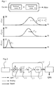
Figure 1 schematically illustrates the distribution of probability P(n) that a number n of photons is measured by an image sensor's pixel, said probability being the combination of quantum uncertainty σq originating from the quantum nature of a light source and technical noise σt originating from the technical equipment used. -
Figure 2 schematically illustrates the principal components of a device for random number generation according to the present invention, these components being a light source, a detector, and a randomness extractor, wherein the detector comprises several sub-elements, as well as the operating principle of the device. -
Figure 3 shows in schematical manner an example of a device for random number generation according to the present invention, the device comprising a LED as a light source, a detector illuminated by said LED, and a randomness extractor which treats the digital outpout of the detector. -
Figures 4a and 4b show, for an ATIK 383L camera, respectively for the camera included in the Nokia N9 mobile telephone, the Fano factor F for various illuminating intensities. -
Figures 5a and 5b show normalized histograms of the photon distributions obtained when using an ATIK 383L CCD camera and a Nokia N9 CMOS camera, respectively, as detector. - In the following, the invention shall be described in detail with reference to the above mentioned figures.
- In a first part, the concept of the proposed system, including its various entropy sources and how the entropy of quantum origin can be extracted, shall be described. In a second part, two different embodiments of the proposed random number generation shall be exposed. Finally, the results obtained with the help of these random number generators in terms of generated random numbers shall be presented, including tests performed on the generated random numbers.
- The concept of the present invention relies on the fact that some properties of a quantum state are unknown before measurement as well as fundamentally unpredictable. One such property, used in most known QRNGs, is the path taken by a photon impinging on a beamsplitter. Another such property is the number of photons produced by a light source in a time interval T. It is the latter effect which is used in the context of this invention. In fact, most light sources emit photons at random times or emit a random number of photons at a time. For ease of the language, both of these effects shall in the further course of the description be embraced by the wording that such light sources emit photons randomly. In any case, it is impossible to predict the number of photons emitted per unit time. This quantum effect is usually called "quantum noise" or "shot noise" and has been shown to be a property of the light field rather than a technical limitation of the light source or of the detector, see e.g. the article « Experimental realization of sub-shot-noise quantum imaging » by G. Brida, M. Genovese, and I. R. Berchera published in Nat. Photon, 4(4):227-230, 2010. Only some particular light sources, namely amplitude-squeezed light, can overcome this fundamental noise, such as reported by Daniel F. Walls in the article « Squeezed states of light » published in Nature, 306:141-146, 1983. Beside these very specific sources, the number of photons emitted by a light source per unit of time T is governed by a Poisson distribution with standard deviation

n the mean number of photons emitted in time interval T. Therefore, this quantum effect may be exploited to realise a QRNG by using a detector capable of resolving this distribution, such as to generate random numbers originating from a fundamentallly random physical process. Such as schematically illustrated infigure 1 , the basic assumptions of this approach consist in that (a) a number n of photoelectrons can be measured by a detector, e.g. an image sensor's pixel, with a probability P(n), (b) this measured distribution will be, assuming that the detector is operating in a linear regime, the combination of quantum uncertainty σq and technical noise σt, and (c) from a single shot measurement these two noise components cannot be distinguished, however the technical noise σt is assumed to be fully deterministic and thus known to an adversary. As will become clear in the following, it is preferable but not necessary for realisation of a QRNG according to the present invention that the inevitable technical noise σt of the detector is smaller, or comparable to, the quantum uncertainty σq originating from the quantum nature of the light source. - A device adapted to realise the above concept comprises, such as shown schematically in
figure 2 , a light source 1, adetector 2, and a randomness extractor 3. The light source 1 may be chosen amongst a light emitting diode (LED), a laser diode (LD), or any other adequate light source, even ambient light, as long as the source emits photons randomly in the meaning defined above. Thedetector 2 comprises several elements and can be modelled, such as also schematically indicated infigure 2 , as lossy channel 2.1 with a transmission probability η, similar to a beamsplitter with a given splitting ratio, followed by a photon sensor 2.2 acting as a photon-to-electron converter with unit efficiency. In this model, the transmission probability η contains all the losses due to the optical elements and the photon sensor's 2.2 quantum efficiency. The photon sensor 2.2 may be realized by any kind of photon detector, in particular by an image sensor with an array of pixels or even by each individual pixel of such an image sensor, like a nowadays commercially available CCD or CMOS camera or similar off-the-shelf components adapted to act as an image sensor and having sufficient light sensitivity. A small quantity of light from the light source 1 impinges on the photon sensor 2.2. This can be done by guiding, reflecting or scattering at the dye, package or assembly level. For each absorbed photon γ, the photon sensor 2.2 generates an electron e-, such as symbolically indicated infigure 2 . Thedetector 2 further comprises processing electronics, in particular an amplifier 2.3 for converting the electron signal received from the photon sensor 2.2 into a voltage and amplifying the voltage signal V as well as an analogue-to-digital converter (ADC) 2.4 which treats the amplified signal V received from the amplifier 2.3 by encoding the amplified signal V representing photon, respectively electron numbers into digital values and sending these values to further processing, i.e. to said randomness extractor 3 which will be described in more detail hereafter. The amplifier 2.3 and the ADC 2.4 may also be chosen amongst commercially available elements. All the above mentioned components may be integrated at a circuit, package or dye level. Advantageously, the randomness extractor can be implemented in software, but is also possible to realize that component by hardware. Furthermore, in the context of the processing electronics, it is possible to define an electron-to-digital conversion factor ζ. If ζ ≥ 1, then for each possible number of electrons generated by the photon sensor 2.2, i.e. for each possible number of photons produced by the light source 1 and absorbed by the sensor 2.2, there is one unique digital value or code at the output of the ADC 2.4, i.e. at the output of thedetector 2. The condition ζ ≥ 1 is thus not an obligatory requirement, but preferred for optimal performance of the device. To complete the model of the detector, noise needs to be added, since noise of different origins like e.g. thermal noise, leakage current, or readout noise cannot be avoided in a real device. In general, this noise follows a normal distribution and adds linearly to the signal, like symbolically indicated infigure 1 . - Consequently, a device such as described above allows to access the shot noise statistics of the light source 1 and thus to generate random numbers of quantum origin. In fact, each photon absorbed by the photon sensor 2.2 will generate an electron, in particular within a corresponding pixel if an image sensor with an array of pixels is used. The number of electrons generated in time interval T is unpredictable, due to the quantum nature of light and of the absorption process. The number of electrons is converted to a voltage, amplified and digitized by components internal or external to the sensor 2.2. It is important that the amount of light and the parameters for the amplification and digitization are appropriate, so that a significant amount of quantum entropy is collected. Not all the entropy generated by this process has a quantum origin, because some is due to classical noise, such as electrical, thermal, amplification, digitization noise or structure given by the image itself. However, an appropriately tuned randomness extractor 3 allows to ensure that the output random numbers have a quantum origin, i.e. that the amount of quantum entropy per output bit is close to 1, such as will become clear in the further course of the description which will also specify in more detail the required amount of light and said parameters for the amplification and digitization.
- In fact, at the output of the
detector 2, a random variable X = X q + X t, where X q and X t are independent random variables taken from the quantum uncertainty distribution D q and the technical noise distribution D t, respectively, is obtained. The technical noise is assumed to be completely known to an adversary, called « Eve » infigure 1 , such that it is only possible to rely upon the quantum entropy generated. Thus, the amount of quantum entropy at the output of thedetector 2 will correspond to the entropy of a Poisson distribution with a mean equal to the average number of photons absorbedn , which - expressed in bits - is this expression can be approximated to

- To collect this entropy entirely, the detector preferably should fulfil the condition ζ ≥ 1 mentioned above. The measured value X can be encoded over b bits, but it is of course possible to encode the value on another basis than the binary system. The entropy H(Xq ) of quantum origin per bit of the output will be on average H(Xq )/b<1. Assuming adequately chosen operating conditions such as mentioned here above, where the ADC 2.4 is not saturated, the entropy s per bit can be approximated by dividing H(Xq ) by the number of output bits of the ADC. To obtain a string of perfectly random bits, i.e. with unit quantum entropy per bit, an extractor is required. As detailed in the article « A randomness extractor for the quantis device » by M. Troyer and R. Renner, published in Id Quantique technical report, 2012, and the content of which is incorporated herein by reference, an extractor computes a number k of high-entropy output bits yj from a number l > k of lower-entropy input bits ri. This can be done by performing a vector-matrix multiplication between the vector formed by the raw bit values ri and a random l x k matrix M (performed modulo 2) according to

- Although the elements of M are randomly distributed, the matrix M serving as randomness extractor 3 usually is a pre-generated constant. For raw input bits with entropy s per bit, the probability that the output vector yj deviates from a perfectly random bit string is bounded by

- Alternatively, an adequate randomness extractor 3 may also be realized by a hash function performing an operation equivalent to the above described matrix-multiplication extractor. This is known to the person skilled in the art and thus doesn't need to be further described at this place.
- In order to demonstrate the feasibility of a device such as described above, comprising a light source 1, a
detector 2, and a randomness extractor 3 of the type just described, as well as the results which may be obtained with a such device, two different embodiments of the proposed random number generator shall now be exposed. In fact, in recent years, image sensors like the ones found in digital cameras and smartphones have improved enormously. Their readout noise nowadays is of the order of a few electrons and their quantum efficiencies can achieve 80%. Besides their ability to resolve quantum noise with high accuracy, such image sensors are intrinsically parallel and offer high data rates. It is thus possible to use such image sensors as a component of a quantum random number generator according to the present invention, which shall in the following be demonstrated both with a commercial astronomy monochrome CCD camera, anATIK 383L camera, and a CMOS sensor in a mobile phone, a Nokia N9 camera. The latter is a colour camera from which only the green pixels were used for the purpose of the following demonstration. -
Figure 3 shows in schematical manner an example of a device for random number generation according to the present invention, the device comprising a light source 1 which is realized by a LED, acamera 2 which is fully and homogeneously illuminated by said LED and the raw data of which, i.e. the binary representation of pixel values produced by thecamera 2, are concatenated and passed through a randomness extractor 3 which in turn outputs quantum random numbers (QRNs) ready to be used. Thecamera 2 is supposed to be formed either by saidATIK 383L camera or said Nokia N9 camera. - At first place, it shall be checked that the above mentioned cameras comply with the manufacturer's specification and that the operating conditions are appropriate for the generation of quantum random numbers. With respect to the latter point, it is important that the photon number distribution does not exceed the region where the camera, respectively the photon detector realized therewith, is linear and that there are enough digital codes to represent each possible number of absorbed photons, i.e. that the condition ζ ≥ 1 already mentioned above is fulfilled.
- To characterise the two cameras mentioned above, a well controlled light source like a LED, such as schematically shown in
figure 3 , is used. According to the principles shown infigure 2 , a number of photons n is absorbed by the photon sensor 2.2 of eachcamera 2 and converted into an equal number of electrons. This charge is in turn converted into a voltage by the amplifier 2.3 and finally digitised by the ADC 2.4. For ease of the description, these components are supposed to form part of thecamera 2 infigure 3 . The amplifier gain, which in commercially available cameras corresponds to the "ISO" setting, is chosen such that each additional input electron will result in an output voltage increase sufficient to be resolved by the ADC, which means that each electron increases the digital output code c by at least 1. This can be checked by illuminating the cameras with a known amount of light. By doing so and using the nominal quantum efficiency of the cameras to infern , one observes ζ = c/e to be 2.3 codes/electron for the ATIK camera, and 1.9 codes/electron for the Nokia camera, as expected from the devices' specifications. - The value of ζ can then be used to infer the number n of absorbed photons from the digital reading. This allows to evaluate the Fano factor F, defined as F=σ2 (n)/
n , which is expected to be 1 for a Poisson distribution. Conversely, the fact that for a linear detector the Fano factor F = 1 can be used to measure Qe and ζ.Figures 4a and 4b show, for the ATIK camera, respectively for the Nokia camera, the Fano factor F obtained in this way for various illuminating intensities of these detectors. Accordingly, both detectors have a large range of intensities where the Fano factor is close to 1, in particular both the ATIK and the Nokia cameras have good linearity, i.e. better than 0.998 for a large range of light intensities. In this range, the statistics are dominated by the quantum uncertainty, i.e. by the shot noise. At strong illuminations, saturation occurs, which means that the Fano factor decreases, as the output is a constant. For the Nokia N9 camera, this happens at intensities corresponding to about 450 to 500 absorbed photons per pixel, whilst for the ATIK camera this happens at about 2 x 10⁴ absorbed photons per pixel. This is due to the high amplifier gain used, which was chosen at ISO 3200. At low illumination intensities, a Fano factor much greater than 1 is observed, which is due to the detector's technical noise. - Image sensors such as CCD and CMOS have various sources of noise, like thermal noise, leakage current and readout noise. Thermal and leakage noise accumulate with integration time, such that it is possible to eliminate or at least greatly reduce these noise sources by using short exposure times, e.g. exposure times of the order of a millisecond, e.g. in the range of 0.1 to 100 milliseconds. In this case, readout noise becomes the dominant source of technical noise and is given by the readout circuit, the amplifier and the ADC. In image sensors, noise is usually counted in electrons (e-). The
ATIK 383L CCD camera and the Nokia N9 CMOS camera have a noise of 10 e-, and 3.3 e-, respectively. However, it is not possible to generalize the values of the exposure times indicated above for all types of cameras, since this also depends on the impinging light intensity. In fact, the exposure time has to be chosen depending on the type of camera, i.e. the type ofdetector 2, and the light intensity such that the detector works in its linear regime and that, preferably, the readout noise becomes the dominant source of technical noise. In practice, the exposure times thus may vary greatly. - In view of the working principles of a QRNG according to the present invention mentioned above, in order to allow using these cameras to generate random numbers of quantum origin, the cameras need to be illuminated such that the mean number of absorbed photons
n is sufficient to give a quantum uncertainty
figures 5a and 5b for theATIK 383L CCD camera and for the Nokia N9 CMOS camera, respectively.Table I: Specifications of and operating parameters employed for the two cameras ATIK 383L Nokia N9 Noise σt (e-) 10 3.3 Saturation (e-) 2 x 10⁴ 450-500 Illumination (e-) 1,5 x 10⁴ 410 Quantum uncertainty σq (e-) 122 20 Offset (e-) 144 -6 Output bits per pixel 16 10 Quantum entropy per pixel 8.9 bits 6.4 bits Quantum entropy per raw bit 0.56 0.64 - At second place, it is then possible on the basis of these facts and operating parameters to use equation (2) to calculate the amount of entropy of quantum origin per pixel, which is 8.9 bits and 6.4 bits for the
ATIK 383L CCD camera and for the Nokia N9 CMOS camera, respectively. These are encoded over 16 and 10 bits, respectively, resulting in an average entropy per output bit of 0.56 for theATIK 383L CCD camera and 0.64 for the Nokia N9 CMOS camera. These results are also figuring in table I. Finally, an adequate extractor 3 is applied according to equation (3) which allows to apply a mixing of the randomness of quantum origin contained in each raw bit obtained from thedetector 2 into the output bits of the randomness extractor 3 forming the final digital output of the QRNG as well as to increase the entropy in the output bits of the randomness extractor 3 as compared to the one in the raw bits obtained from thedetector 2. This is an important reason why it is preferable, but not necessary for realisation of a QRNG according to the present invention that the inevitable technical noise at of thedetector 2 is smaller, or comparable to, the quantum uncertainty σq. The choice of the extractor 3, in particular with respect to its dimension k, is done according to the above mentioned principles. In fact, like mentioned above, the detected photon number distribution can be described by a Poisson distribution and its minimum entropy can be approximated by equation (1). Thus, the size and the compression factor of the extractor 3 may be tuned such as to ensure that each bit of output from the extractor has an amount of quantum entropy close to 1 by determining the size and the compression factor of the randomness extractor so that the number of output bits per measurement is smaller than the minimal entropy of the detected photon number distribution. In the particular case of the matrix-multiplication extractor introduced above, this can be done using equation (4) and ensuring that the extractor's parameters l and k, for a mean entropy s per bit, are chosen such as to ensure that the probability ε that the extractor's output bit string deviates from a perfectly random one is small. In particular, equation (4) above allows to calculate that by using the camera in the Nokia cell phone and an extractor with a compression factor of 4, for example with k = 500 and l = 2000, it would take ∼10118 trials to notice a deviation from a perfectly random bit string. Thus, if everybody on earth used such a device constantly at 1Gbps, it would take ∼1080 times the age of the universe for one to notice a deviation from a perfectly random bit string. - In order to test the quality of random numbers generated in such manner, 48 frames corresponding to approximately 5 Gbits of raw random numbers generated using the above described framework were collected and processed on a computer through an extractor with a 2000 bit input vector and a 500 bit output vector, which allowed to generate 1.25 Gbits of random numbers. Although random number generators are notoriously hard to test, it is possible to check the generated bit string for specific weaknesses. A first testing step may be to individuate potential problems of the system and then test for them. In the present case, the generated random bit string was tested before extraction. At this stage, the entropy per bit is still considerably less than unity; moreover, possible errors could arise from damaged or dead pixels of the
detector 2 and from correlations between pixel values due to electrical noise. In fact, besides increasing the mean entropy per bit, the randomness extractor 3 also ensures that if some pixels become damaged, covered by dust, or suffer from any other problem, an extremely good quality of the randomness is maintained. A second testing step may consist in the "die harder" randomness tests which can be applied on both the extracted bit strings, i.e. the raw random numbers produced at the output of thedetector 2 and the random numbers deliverd by the randomness extractor 3. This set of tests contains the NIST test, the diehard tests and some extra tests. The QRNG according to the present invention passed all these tests. - Next to the quality of the random numbers generated, other parameters of a QRNG are important, e.g. the production speed of the random numbers, as well as affordability and portability of the device. In fact, for many applications, such as the generation of cryptographic keys for conventional use or gaming, speed is not as important as the affordability and portability which are provided by this system. Nevertheless, a quantum random number generator based on an image sensor can provide very reasonable performance in terms of speed. Consumer grade devices such as the CCD and CMOS detectors used acquire data at rates between 100 Megapixels per second and 1 Gigapixel per second. After the necessary processing, each pixel will typically provide 3 random bits so that rates between 300 Mbps and 3 Gbps can be obtained. To sustain such high data rates, processing can be done either on a Field Programmable Gate Array (FPGA) or could be embedded directly on a CMOS sensor chip, including the processing step realized by the randomness extractor 3 which in that case is featured by hardware. Alternatively, implementing the randomness extractor 3 fully in the software of a consumer device is possible and can sustain random bit rates greater than 1 Mbps, largely sufficient for most consumer applications. Therefore, it is possible to realize a device for quantum random number generation according to the present invention by using technology compatible with consumer and portable electronics.
- Thus, random numbers of a quantum origin can be extracted by illuminating a known image sensor and applying specific operating parameters to the photon sensor 2.2, the processing electronics, as well as the randomness extractor 3. In fact, according to the above figuring explanations with respect to a device for random number generation based on an optical process of quantum nature, a corresponding method for random number generation comprises the steps of providing a light source 1 emitting photons randomly, providing a light detector 2 adapted to absorb the randomly emitted photons and to measure the number n of photons produced by said light source 1 in a time interval T and comprising a photon sensor 2.2, an amplifier 2.3, and an analogue-to-digital converter 2.4, and providing a randomness extractor 3, such as to allow detecting the number n of photons produced by said light source 1 in a time interval T and converting said number of photons into a corresponding number of electrons with the help of said photon sensor 2.2 of detector 2, converting the electron signal received from the photon sensor 2.2 into a voltage and amplifying the voltage signal V with the help of said amplifier 2.3 of detector 2, and treating the amplified signal V received from the amplifier 2.3 by encoding the amplified signal V into digital values with the help of said analogue-to-digital converter 2.4 of detector 2 and sending these values to the randomness extractor 3 for further processing such as to produce quantum random numbers (QRNs) based on said number n of photons produced by the light source 1 in a time interval T.
- The photon sensor 2.2 of
detector 2 is illuminated by the light source 1 during a time interval T which is chosen such that the mean number of absorbed photonsis sufficient to give a quantum uncertainty

detector 2 is illuminated by the light source 1 with a photon intensity situated within a range of intensities where the Fano factor of the photon sensor 2.2 is close to 1. It is also possible to control the mean number of absorbed photons by adjusting the exposure time of the camera, within the limit that the exposure time needs to be chosen such that the camera works in its linear regime. - Advantageously, the raw digital values ri generated at the ouput of
detector 2, respectively the digital values yj at the output of the randomness extractor 3 are encoded over b bits, or are encoded on another basis than the binary system. - Finally, it is to be noted that the present invention is also related to computer program means stored in a computer readable medium adapted to implement the above described method.
- In light of the above description of the device and of the corresponding method according to the present invention, its advantages are clear. Most importantly, a device for quantum random number generation according to the present invention allows to generate high quality random numbers of quantum origin since being based on a fundamentally random physical process. The random numbers may be generated at a high rate. The device can be implemented with commercially available imaging devices such as CMOS and CCD cameras which are small and low cost. Also, it can be easily integrated on a printed circuit board. In fact, all elements such as light source, light detector, and randomness extractor, as well as other, optional components like for self-testing and further data processing such as encryption and transmission can be integrated at the system, circuit, package or dye level, which improves size, ease of use, security, reliability and energy efficiency of the whole device. Furthermore, many mobile and computing devices nowadays include an image sensor of a type adapted to be used, either by minor modification or in some cases directly, as a detector such as required in a device according to the present invention to generate quantum random numbers. Such image sensors have a low power consumption compatible with mobile and battery powered applications. The randomness extractor can be implemented in hardware or, preferably, by software. Due to its small size, the device can be integrated with other components such as a camera, encryption, transmission, diagnostic device etc.; in particular, given that many consumer electronics articles are anyway equipped with an image sensor adapted to be used for the purposes of the present invention, the latter may advantageously be integrated with such components and corresponding software into a computer, a telephone, in particular mobile computers or telephones, tablets, network cryptographic devices, personal cryptographic devices, electronic wallets, or any other type of similar instruments. Thus, in general, the simplicity and performance of a device according to the present invention allows, in contrast to existing QRNG, to make widespread use of physical quantum random number generators, with an important impact on information security.
Claims (17)
- Device for random number generation based on an optical process of quantum nature comprising- a light source (1) emitting photons randomly,- a light detector (2) comprising a photon sensor (2.2) adapted to absorb the randomly emitted photons,- an amplifier (2.3) for converting an electron signal received from the photon sensor (2.2) into a voltage and amplifying the voltage signal (V), as well as- an analogue-to-digital converter (ADC/2.4) for treating the amplified signal (V) received from the amplifier (2.3) by encoding the amplified signal (V) into digital values (d) and sending these digital values (d) to a randomness extractor (3) of the device for further processing,- the randomness extractor (3) being adapted to generate a number k of high-entropy output bits yj from a number l > k of lower-entropy raw input bits ri,characterised by the fact that- the photon sensor (2.2) of the detector (2) is adapted to operate in a linear regime and acts as a photon-to-electron converter to allow the detector (2) to be adapted to measure a number n of photons produced by said light source (1) in a time interval T, such as to produce quantum random numbers (QRNs) based on said number n of photons produced by the light source (1) in a time interval T.
- Device according to the preceding claim, characterised by the fact that the randomness extractor (3) is adapted, for raw input bits ri with entropy s per bit, to generate output bits yj having a probability that the output bits yj deviate from a perfectly random bit string bounded by ε=2-(sl-k)/2.
- Device according to one of the preceding claims, characterised by the fact that the light source (1) is chosen amongst the group of light sources comprising a light emitting diode (LED), a laser diode (LD), ambient light, or any other adequate light source emitting photons randomly.
- Device according to one of the preceding claims, characterised by the fact that the photon sensor (2.2) is chosen amongst the group of photon detectors comprising a CCD camera, a CMOS camera, in particular an image sensor with an array of pixels, or any other adequate photon detector having a sufficient single photon resolution.
- Device according to one of the preceding claims, characterised by the fact that the analogue-to-digital converter (2.4) has an electron-to-digital conversion factor ζ fulfilling the condition ζ ≥ 1.
- Device according to one of the preceding claims, characterised by the fact that the randomness extractor (3) is implemented by software or by hardware.
- Device according to one of the preceding claims, characterised by the fact that the randomness extractor (3) is realized by a hash function or by a vector-matrix multiplication between a vector formed by the raw bit values ri generated at the output of detector (2) and a random l x k matrix M according to

- Device according to one of the preceding claims, characterised by the fact that the randomness extractor (3) is determined such as to produce digital output bit values yj of the randomness extractor (3) having an amount of quantum entropy per output bit close to 1.
- Device according to one of the preceding claims, characterised by the fact that the components of the device are integrated at a system, circuit, package or dye level, preferably on a Field Programmable Gate Array (FPGA) or directly on a CMOS sensor chip.
- Apparatus, in particular a computer, a telephone, a mobile computer or mobile telephone, a tablet computer, a smart phone, a network cryptographic device, a personal cryptographic device, an electronic wallet, or any other type of similar instruments, characterised by the fact that it comprises a device according to one of the preceding claims.
- Method for random number generation based on an optical process of quantum nature comprising the steps of- providing a light source (1) emitting photons randomly,- providing a light detector (2) comprising a photon sensor (2.2) adapted to absorb the randomly emitted photons, an amplifier (2.3), and an analogue-to-digital converter (2.4),- converting an electron signal received from the photon sensor (2.2) into a voltage and amplifying the voltage signal (V) with the help of said amplifier (2.3) of detector (2),- treating the amplified signal (V) received from the amplifier (2.3) by encoding the amplified signal (V) into digital values with the help of said analogue-to-digital converter (2.4) of detector (2) and sending these values to a randomness extractor (3) for further processing, and- providing a randomness extractor (3) being adapted to generate a number k of high-entropy output bits yj from a number l > k of lower-entropy raw input bits ri,characterised by the fact that the method further comprises the step of- operating the photon sensor (2.2) of the detector (2) in a linear regime such as to allow detecting a number n of photons produced by said light source (1) in a time interval T and converting said number of photons into a corresponding number of electrons with the help of said photon sensor (2.2) of the detector (2), such as to produce quantum random numbers (QRNs) based on said number n of photons produced by the light source (1) in a time interval T.
- Method according to the preceding claim, characterised by the fact that the method further comprises the step of generating by use of the randomness extractor (3), for raw input bits ri with entropy s per bit, output bits yj having a probability that the output bits yj deviate from a perfectly random bit string bounded by ε=2 -(sl-k)/2.
- Method according to one of the preceding claims 11 to 12, characterised by the fact that the photon sensor (2.2) of detector (2) is illuminated by the light source (1) during a time interval T adapted so that the mean number of absorbed photons
n is sufficient to give a quantum uncertainty
- Method according to one of the preceding claims 11 to 13, characterised by the fact that the photon sensor (2.2) of detector (2) is illuminated by the light source (1) with a photon intensity situated within a range of intensities where the Fano factor of the photon sensor (2.2) is close to 1.
- Method according to one of the preceding claims 11 to 14, characterised by the fact that an exposure time during which the photon sensor (2.2) is illuminated by the light source (1) is selected such that the detector works in its linear regime.
- Method according to one of the preceding claims 11 to 15, characterised by the fact that the raw digital values ri generated at the output of detector (2), respectively the digital values yj at the output of the randomness extractor (3) are encoded over b bits, or are encoded on another basis than the binary system.
- Computer program means stored in a computer readable medium adapted to implement the method according to one of the preceding claims 11 to 16.
Priority Applications (8)
| Application Number | Priority Date | Filing Date | Title |
|---|---|---|---|
| EP14166272.6A EP2940923B1 (en) | 2014-04-28 | 2014-04-28 | Method and device for optics based quantum random number generator |
| KR1020150058971A KR102287220B1 (en) | 2014-04-28 | 2015-04-27 | Method and device for optics based quantum random number generation |
| JP2015090002A JP6456763B2 (en) | 2014-04-28 | 2015-04-27 | Method and device for quantum random number generation based on optical system |
| US14/697,320 US9747077B2 (en) | 2014-04-28 | 2015-04-27 | Method and device for optics based quantum random number generation |
| US14/937,202 US9772820B2 (en) | 2014-04-28 | 2015-11-10 | Method and device for optics based quantum random number generation |
| KR1020187016501A KR101977405B1 (en) | 2014-04-28 | 2016-10-31 | Method and device for optical based quantum random number generation |
| JP2018525398A JP6908606B2 (en) | 2014-04-28 | 2016-10-31 | Methods and devices for generating quantum random numbers based on optics |
| US15/659,454 US10331412B2 (en) | 2014-04-28 | 2017-07-25 | Method and device for optics based quantum random number generation |
Applications Claiming Priority (1)
| Application Number | Priority Date | Filing Date | Title |
|---|---|---|---|
| EP14166272.6A EP2940923B1 (en) | 2014-04-28 | 2014-04-28 | Method and device for optics based quantum random number generator |
Publications (2)
| Publication Number | Publication Date |
|---|---|
| EP2940923A1 EP2940923A1 (en) | 2015-11-04 |
| EP2940923B1 true EP2940923B1 (en) | 2018-09-05 |
Family
ID=50732787
Family Applications (1)
| Application Number | Title | Priority Date | Filing Date |
|---|---|---|---|
| EP14166272.6A Active EP2940923B1 (en) | 2014-04-28 | 2014-04-28 | Method and device for optics based quantum random number generator |
Country Status (4)
| Country | Link |
|---|---|
| US (3) | US9747077B2 (en) |
| EP (1) | EP2940923B1 (en) |
| JP (2) | JP6456763B2 (en) |
| KR (2) | KR102287220B1 (en) |
Families Citing this family (49)
| Publication number | Priority date | Publication date | Assignee | Title |
|---|---|---|---|---|
| US10019235B2 (en) * | 2011-09-30 | 2018-07-10 | Los Alamos National Security, Llc | Quantum random number generators |
| EP2940923B1 (en) * | 2014-04-28 | 2018-09-05 | Université de Genève | Method and device for optics based quantum random number generator |
| AU2015255601B2 (en) | 2014-05-09 | 2020-02-27 | Quantum Numbers Corp. | Method for generating random numbers and associated random number generator |
| US10356061B2 (en) * | 2014-11-28 | 2019-07-16 | Fiske Software, Llc | Hiding a public key exchange in noise |
| KR101729663B1 (en) * | 2015-12-31 | 2017-04-24 | 에스케이텔레콤 주식회사 | Apparatus and method for managing performance of random number generator based on quantum shot noise |
| CN108604425B (en) * | 2016-02-04 | 2021-06-08 | 国立大学法人北海道大学 | Random number sequence generating device, quantum cryptographic transmitter and quantum cryptographic communication system |
| WO2017151061A1 (en) * | 2016-03-01 | 2017-09-08 | National University Of Singapore | Method and system for random number generation |
| DE102016207451A1 (en) * | 2016-04-29 | 2017-11-02 | Siemens Aktiengesellschaft | Method and apparatus for generating random bits |
| CN110325960B (en) | 2016-05-05 | 2023-12-26 | Id量子技术公司 | Quantum image sensor quantum random number generation |
| KR101963393B1 (en) | 2016-09-27 | 2019-03-28 | 한국과학기술연구원 | System and method for generating random number using image sensor, method for forming database, and computer readable recording medium thereof |
| EP3306464B1 (en) * | 2016-10-09 | 2021-09-29 | Université de Genève | Method and device for quantum random number generation |
| CN108369496B (en) * | 2016-10-14 | 2020-11-27 | 华为技术有限公司 | A device and method for generating random numbers |
| GB2560873B (en) * | 2016-12-23 | 2020-01-01 | Crypta Labs Ltd | Quantum Random Number Generator |
| EP3343194B1 (en) * | 2016-12-28 | 2019-08-28 | ID Quantique S.A. | Measuring device and method for optical fibers |
| CN108738361B (en) * | 2017-02-24 | 2024-03-12 | Id量子技术公司 | Quantum noise-based random number generation device utilizing multiple light sources |
| JP6852882B2 (en) * | 2017-03-02 | 2021-03-31 | 国立研究開発法人情報通信研究機構 | Physical random number distillation equipment and method |
| KR101985492B1 (en) * | 2017-03-07 | 2019-06-03 | 아이디 퀀티크 에스.에이. | Apparatus for generating random number based on quantum shot noise |
| CN107094076B (en) * | 2017-04-14 | 2018-09-25 | 江苏亨通问天量子信息研究院有限公司 | Secret communication method based on quantum true random number and communication system |
| JP6685969B2 (en) * | 2017-05-23 | 2020-04-22 | 日本電信電話株式会社 | Extracted physical random number generation device, extracted physical random number generation method, program |
| US10168996B1 (en) | 2018-01-15 | 2019-01-01 | Quantum Numbers Corp. | Method and system for generating a random bit sample |
| GB2575043B (en) * | 2018-06-25 | 2021-05-19 | Toshiba Kk | Apparatus and method for mearuring a signal |
| WO2020113153A1 (en) * | 2018-11-28 | 2020-06-04 | Andrew Pomerance | Random symbol generation system and method |
| WO2020261419A1 (en) * | 2019-06-26 | 2020-12-30 | 日本電信電話株式会社 | Quantum random number generation device and quantum random number generation method |
| KR102123820B1 (en) * | 2019-07-31 | 2020-06-23 | 국민대학교산학협력단 | Apparatus and method for generating computer-executable lightweight random number |
| US11895232B1 (en) | 2019-10-04 | 2024-02-06 | Wells Fargo Bank, N.A. | Systems and methods for quantum entanglement authentication |
| CN110750236A (en) * | 2019-10-28 | 2020-02-04 | 安徽安匠信息科技有限公司 | Quantum random number generator based on CMOS image sensor |
| WO2021090007A1 (en) | 2019-11-05 | 2021-05-14 | Crypta Labs Ltd | Quantum random number generator |
| US20220398069A1 (en) * | 2019-11-14 | 2022-12-15 | Danmarks Tekniske Universitet | A quantum random number generator |
| US12099997B1 (en) | 2020-01-31 | 2024-09-24 | Steven Mark Hoffberg | Tokenized fungible liabilities |
| WO2021163049A1 (en) * | 2020-02-10 | 2021-08-19 | Jpmorgan Chase Bank, N.A. | Method and system for verification of random numbers |
| KR102325225B1 (en) * | 2020-04-24 | 2021-11-11 | 주식회사 아이에이네트웍스 | Photo sensor shrinkage package module |
| CN111726220A (en) * | 2020-06-03 | 2020-09-29 | 太原理工大学 | Real-time and high-speed generation of quantum random codes based on chaos amplification of quantum noise |
| CN112511298B (en) * | 2020-12-02 | 2022-03-18 | 中南大学 | Random number generation method and quantum key distribution method based on Bose sampling |
| KR102436948B1 (en) * | 2020-12-07 | 2022-08-25 | 경희대학교 산학협력단 | Method and apparatus of counterfactual clock synchronization |
| WO2022124984A1 (en) * | 2020-12-07 | 2022-06-16 | National University Of Singapore | Quantum key token |
| EP4016350A1 (en) * | 2020-12-15 | 2022-06-22 | Id Quantique Sa | Random number generator diagnosis method |
| US12524692B2 (en) * | 2021-06-19 | 2026-01-13 | Surjeet Rajendran | Protocols to exploit non linear quantum mechanics |
| KR102574706B1 (en) * | 2021-08-02 | 2023-09-06 | 재단법인대구경북과학기술원 | Method for min-entropy estimation and apparatus thereof |
| US11477021B1 (en) | 2022-03-09 | 2022-10-18 | Tuatara QRNG, LLC | Systems and methods for universal three-dimensional quantum random number generation and encryption |
| US11526330B1 (en) | 2022-03-16 | 2022-12-13 | Tuatara QRNG, LLC | Universal interferometer and systems and methods for universal three-dimensional quantum random number generation |
| KR102752730B1 (en) * | 2022-09-16 | 2025-01-10 | 주식회사 큐레몬 | Quantum random number generation device having address conversion control circuit, and computing system having same |
| EP4390664A1 (en) | 2022-12-19 | 2024-06-26 | ID Quantique S.A. | Random number generator |
| KR20250121595A (en) | 2022-12-19 | 2025-08-12 | 아이디 퀀티크 에스.에이. | random number generator |
| EP4390663A1 (en) | 2022-12-19 | 2024-06-26 | ID Quantique S.A. | Random number generator |
| EP4390662A1 (en) | 2022-12-19 | 2024-06-26 | ID Quantique S.A. | Random number generator |
| US12598396B2 (en) | 2023-03-24 | 2026-04-07 | Samsung Electronics Co., Ltd. | Random number generator for multichannel image sensing device |
| GB2628660A (en) * | 2023-03-31 | 2024-10-02 | Crypta Labs Ltd | Improvements in and relating to random number generation |
| FR3148507B1 (en) * | 2023-05-04 | 2025-10-03 | Thales Sa | Device for generating an optical signal for quantum key distribution |
| MA62931B1 (en) * | 2023-10-30 | 2025-07-31 | Epiquantum | Random number generator |
Family Cites Families (36)
| Publication number | Priority date | Publication date | Assignee | Title |
|---|---|---|---|---|
| JPS6197746A (en) * | 1984-10-15 | 1986-05-16 | インタ−ナショナル ビジネス マシ−ンズ コ−ポレ−ション | Random number generator |
| US4833633A (en) | 1984-10-25 | 1989-05-23 | University Of Rochester | Opto-electronic random number generating system and computing systems based thereon |
| JPH0637345A (en) * | 1992-07-17 | 1994-02-10 | Fujitsu Ltd | Radiation detector |
| US5732138A (en) | 1996-01-29 | 1998-03-24 | Silicon Graphics, Inc. | Method for seeding a pseudo-random number generator with a cryptographic hash of a digitization of a chaotic system |
| CA2217916A1 (en) | 1996-10-09 | 1998-04-09 | Dew Engineering And Development Limited | Random number generator and method for same |
| US6831980B1 (en) * | 1996-10-09 | 2004-12-14 | Activcard Ireland Limited | Random number generator and method for same |
| DE19641754A1 (en) | 1996-10-10 | 1998-04-16 | Deutsche Telekom Ag | Optical random generator based on the single photon statistics on the optical beam splitter |
| US6249009B1 (en) * | 1997-06-16 | 2001-06-19 | Hong J. Kim | Random number generator |
| US6539410B1 (en) * | 1999-03-17 | 2003-03-25 | Michael Jay Klass | Random number generator |
| SE516567C2 (en) | 2000-06-07 | 2002-01-29 | Anoto Ab | Procedure and apparatus for secure wireless transmission of information |
| EP1303978A4 (en) * | 2000-07-05 | 2006-08-09 | Vision Sciences Inc | DYNAMIC RANGE COMPRESSION METHOD |
| US7197523B2 (en) | 2001-05-09 | 2007-03-27 | Magiq Technologies, Inc. | Efficient use of detectors for random number generation |
| JP2003036168A (en) * | 2001-07-25 | 2003-02-07 | Mitsubishi Electric Corp | Random number generation device and random number generation method |
| JP2004126484A (en) * | 2002-10-01 | 2004-04-22 | Chaos Sangyo Gijutsu Kenkyusho:Kk | How to compress and encrypt image data |
| US7284024B1 (en) | 2003-02-07 | 2007-10-16 | Magiq Technologies, Inc. | Quantum noise random number generator |
| JP2005250714A (en) * | 2004-03-03 | 2005-09-15 | Univ Nihon | Photon random number generator |
| JP2006086981A (en) * | 2004-09-17 | 2006-03-30 | Fujitsu Ltd | Switched capacitor circuit and pipeline A / D conversion circuit |
| JP4308170B2 (en) * | 2005-06-10 | 2009-08-05 | 本田技研工業株式会社 | Image sensor |
| EP1907925A4 (en) * | 2005-06-16 | 2009-06-03 | Univ Hong Kong Chinese | Quantum random number generators |
| DE602006002242D1 (en) | 2006-02-15 | 2008-09-25 | Jaycrypto Ltd | Method and device for generating initial values for a random number generator |
| US7849121B2 (en) * | 2006-04-20 | 2010-12-07 | Hewlett-Packard Development Company, L.P. | Optical-based, self-authenticating quantum random number generators |
| ITMI20062483A1 (en) * | 2006-12-22 | 2008-06-23 | Milano Politecnico | QUANTUM GENERATOR OF RANDOM NUMBERS AND RELATIVE GENERATION METHOD |
| DE102007008021A1 (en) * | 2007-02-15 | 2008-08-21 | Tecdata Ag | Method for measuring information |
| JP4952461B2 (en) | 2007-09-12 | 2012-06-13 | ソニー株式会社 | Random number generation apparatus and random number generation method |
| DE102008018678B4 (en) * | 2008-04-14 | 2011-02-03 | Siemens Aktiengesellschaft | Apparatus and method for generating a random bit string |
| GB0915000D0 (en) * | 2009-08-27 | 2009-09-30 | Univ Bruxelles | Quantum random number generation |
| US8554814B2 (en) | 2010-08-20 | 2013-10-08 | The Governing Council Of The University Of Toronto | Random signal generator using quantum noise |
| CN101980146B (en) * | 2010-10-13 | 2012-10-24 | 华东师范大学 | Photon-number distinguishable detection-based true random number generator |
| WO2012136763A2 (en) * | 2011-04-05 | 2012-10-11 | Intrinsic Id B.V. | Random number generating system based on memory start-up noise |
| US8379848B2 (en) | 2011-07-07 | 2013-02-19 | Cape Light Institute, Inc. | Method of providing a portable true random number generator based on the microstructure and noise found in digital images |
| US9189201B2 (en) * | 2011-09-20 | 2015-11-17 | Qualcomm Incorporated | Entropy source with magneto-resistive element for random number generator |
| US10019235B2 (en) * | 2011-09-30 | 2018-07-10 | Los Alamos National Security, Llc | Quantum random number generators |
| EP2592547A1 (en) | 2011-11-09 | 2013-05-15 | Novomatic AG | Device for generating true random numbers and gaming system |
| US8787564B2 (en) * | 2011-11-30 | 2014-07-22 | Certicom Corp. | Assessing cryptographic entropy |
| EP2940923B1 (en) * | 2014-04-28 | 2018-09-05 | Université de Genève | Method and device for optics based quantum random number generator |
| US20170030059A1 (en) | 2016-10-14 | 2017-02-02 | Jun-Qi Lin | Seamless connecting drain structure of metallic sink |
-
2014
- 2014-04-28 EP EP14166272.6A patent/EP2940923B1/en active Active
-
2015
- 2015-04-27 US US14/697,320 patent/US9747077B2/en active Active
- 2015-04-27 JP JP2015090002A patent/JP6456763B2/en active Active
- 2015-04-27 KR KR1020150058971A patent/KR102287220B1/en active Active
- 2015-11-10 US US14/937,202 patent/US9772820B2/en active Active
-
2016
- 2016-10-31 KR KR1020187016501A patent/KR101977405B1/en active Active
- 2016-10-31 JP JP2018525398A patent/JP6908606B2/en active Active
-
2017
- 2017-07-25 US US15/659,454 patent/US10331412B2/en active Active
Also Published As
| Publication number | Publication date |
|---|---|
| KR20180102068A (en) | 2018-09-14 |
| JP2015215888A (en) | 2015-12-03 |
| KR102287220B1 (en) | 2021-08-09 |
| US9772820B2 (en) | 2017-09-26 |
| EP2940923A1 (en) | 2015-11-04 |
| KR101977405B1 (en) | 2019-08-28 |
| US20170060534A1 (en) | 2017-03-02 |
| KR20150124405A (en) | 2015-11-05 |
| JP6908606B2 (en) | 2021-07-28 |
| JP2018534624A (en) | 2018-11-22 |
| US20170010865A1 (en) | 2017-01-12 |
| JP6456763B2 (en) | 2019-01-23 |
| US9747077B2 (en) | 2017-08-29 |
| US10331412B2 (en) | 2019-06-25 |
| US20170337037A1 (en) | 2017-11-23 |
Similar Documents
| Publication | Publication Date | Title |
|---|---|---|
| EP2940923B1 (en) | Method and device for optics based quantum random number generator | |
| CN107066236B (en) | Method and apparatus for optical-based quantum random number generation | |
| US11442698B2 (en) | Quantum random number generators | |
| JP7025458B2 (en) | Quantum random number generator | |
| Sanguinetti et al. | Quantum random number generation on a mobile phone | |
| Herrero-Collantes et al. | Quantum random number generators | |
| Park et al. | Practical true random number generator using CMOS image sensor dark noise | |
| Zhang et al. | Portable true random number generator for personal encryption application based on smartphone camera | |
| EP4487205A1 (en) | Cryptographic key and random number generation based on quantum systems | |
| Aungskunsiri et al. | Quantum random number generation based on multi-photon detection | |
| Bisadi | All-silicon-based photonic quantum random number Generators | |
| Lakshmi et al. | A novel technique for random number generation using CMOS image sensor | |
| Martin | Quantum random number generation on a mobile phone | |
| Ge et al. | Low-cost commercial optoelectronic components-driven quantum random number generator with theoretical 64 Gb/s throughput via parallelization | |
| Yicheng | A ULTRA-FAST QUANTUM RANDOM NUMBER GENERATOR |
Legal Events
| Date | Code | Title | Description |
|---|---|---|---|
| PUAI | Public reference made under article 153(3) epc to a published international application that has entered the european phase |
Free format text: ORIGINAL CODE: 0009012 |
|
| AK | Designated contracting states |
Kind code of ref document: A1 Designated state(s): AL AT BE BG CH CY CZ DE DK EE ES FI FR GB GR HR HU IE IS IT LI LT LU LV MC MK MT NL NO PL PT RO RS SE SI SK SM TR |
|
| AX | Request for extension of the european patent |
Extension state: BA ME |
|
| 17P | Request for examination filed |
Effective date: 20160427 |
|
| RBV | Designated contracting states (corrected) |
Designated state(s): AL AT BE BG CH CY CZ DE DK EE ES FI FR GB GR HR HU IE IS IT LI LT LU LV MC MK MT NL NO PL PT RO RS SE SI SK SM TR |
|
| GRAP | Despatch of communication of intention to grant a patent |
Free format text: ORIGINAL CODE: EPIDOSNIGR1 |
|
| STAA | Information on the status of an ep patent application or granted ep patent |
Free format text: STATUS: GRANT OF PATENT IS INTENDED |
|
| RIC1 | Information provided on ipc code assigned before grant |
Ipc: G06F 7/58 20060101ALI20180411BHEP Ipc: H04L 9/08 20060101AFI20180411BHEP |
|
| INTG | Intention to grant announced |
Effective date: 20180424 |
|
| GRAS | Grant fee paid |
Free format text: ORIGINAL CODE: EPIDOSNIGR3 |
|
| GRAA | (expected) grant |
Free format text: ORIGINAL CODE: 0009210 |
|
| STAA | Information on the status of an ep patent application or granted ep patent |
Free format text: STATUS: THE PATENT HAS BEEN GRANTED |
|
| AK | Designated contracting states |
Kind code of ref document: B1 Designated state(s): AL AT BE BG CH CY CZ DE DK EE ES FI FR GB GR HR HU IE IS IT LI LT LU LV MC MK MT NL NO PL PT RO RS SE SI SK SM TR |
|
| REG | Reference to a national code |
Ref country code: GB Ref legal event code: FG4D |
|
| REG | Reference to a national code |
Ref country code: CH Ref legal event code: EP |
|
| REG | Reference to a national code |
Ref country code: AT Ref legal event code: REF Ref document number: 1039139 Country of ref document: AT Kind code of ref document: T Effective date: 20180915 |
|
| REG | Reference to a national code |
Ref country code: CH Ref legal event code: NV Representative=s name: PER MENS INTELLECTUAL PROPERTY CONSULTING SARL, CH |
|
| REG | Reference to a national code |
Ref country code: IE Ref legal event code: FG4D |
|
| REG | Reference to a national code |
Ref country code: DE Ref legal event code: R096 Ref document number: 602014031618 Country of ref document: DE |
|
| REG | Reference to a national code |
Ref country code: NL Ref legal event code: FP |
|
| REG | Reference to a national code |
Ref country code: LT Ref legal event code: MG4D |
|
| PG25 | Lapsed in a contracting state [announced via postgrant information from national office to epo] |
Ref country code: GR Free format text: LAPSE BECAUSE OF FAILURE TO SUBMIT A TRANSLATION OF THE DESCRIPTION OR TO PAY THE FEE WITHIN THE PRESCRIBED TIME-LIMIT Effective date: 20181206 Ref country code: SE Free format text: LAPSE BECAUSE OF FAILURE TO SUBMIT A TRANSLATION OF THE DESCRIPTION OR TO PAY THE FEE WITHIN THE PRESCRIBED TIME-LIMIT Effective date: 20180905 Ref country code: BG Free format text: LAPSE BECAUSE OF FAILURE TO SUBMIT A TRANSLATION OF THE DESCRIPTION OR TO PAY THE FEE WITHIN THE PRESCRIBED TIME-LIMIT Effective date: 20181205 Ref country code: NO Free format text: LAPSE BECAUSE OF FAILURE TO SUBMIT A TRANSLATION OF THE DESCRIPTION OR TO PAY THE FEE WITHIN THE PRESCRIBED TIME-LIMIT Effective date: 20181205 Ref country code: RS Free format text: LAPSE BECAUSE OF FAILURE TO SUBMIT A TRANSLATION OF THE DESCRIPTION OR TO PAY THE FEE WITHIN THE PRESCRIBED TIME-LIMIT Effective date: 20180905 Ref country code: LT Free format text: LAPSE BECAUSE OF FAILURE TO SUBMIT A TRANSLATION OF THE DESCRIPTION OR TO PAY THE FEE WITHIN THE PRESCRIBED TIME-LIMIT Effective date: 20180905 Ref country code: FI Free format text: LAPSE BECAUSE OF FAILURE TO SUBMIT A TRANSLATION OF THE DESCRIPTION OR TO PAY THE FEE WITHIN THE PRESCRIBED TIME-LIMIT Effective date: 20180905 |
|
| REG | Reference to a national code |
Ref country code: AT Ref legal event code: MK05 Ref document number: 1039139 Country of ref document: AT Kind code of ref document: T Effective date: 20180905 |
|
| PG25 | Lapsed in a contracting state [announced via postgrant information from national office to epo] |
Ref country code: AL Free format text: LAPSE BECAUSE OF FAILURE TO SUBMIT A TRANSLATION OF THE DESCRIPTION OR TO PAY THE FEE WITHIN THE PRESCRIBED TIME-LIMIT Effective date: 20180905 Ref country code: LV Free format text: LAPSE BECAUSE OF FAILURE TO SUBMIT A TRANSLATION OF THE DESCRIPTION OR TO PAY THE FEE WITHIN THE PRESCRIBED TIME-LIMIT Effective date: 20180905 Ref country code: HR Free format text: LAPSE BECAUSE OF FAILURE TO SUBMIT A TRANSLATION OF THE DESCRIPTION OR TO PAY THE FEE WITHIN THE PRESCRIBED TIME-LIMIT Effective date: 20180905 |
|
| PG25 | Lapsed in a contracting state [announced via postgrant information from national office to epo] |
Ref country code: PL Free format text: LAPSE BECAUSE OF FAILURE TO SUBMIT A TRANSLATION OF THE DESCRIPTION OR TO PAY THE FEE WITHIN THE PRESCRIBED TIME-LIMIT Effective date: 20180905 Ref country code: IT Free format text: LAPSE BECAUSE OF FAILURE TO SUBMIT A TRANSLATION OF THE DESCRIPTION OR TO PAY THE FEE WITHIN THE PRESCRIBED TIME-LIMIT Effective date: 20180905 Ref country code: CZ Free format text: LAPSE BECAUSE OF FAILURE TO SUBMIT A TRANSLATION OF THE DESCRIPTION OR TO PAY THE FEE WITHIN THE PRESCRIBED TIME-LIMIT Effective date: 20180905 Ref country code: EE Free format text: LAPSE BECAUSE OF FAILURE TO SUBMIT A TRANSLATION OF THE DESCRIPTION OR TO PAY THE FEE WITHIN THE PRESCRIBED TIME-LIMIT Effective date: 20180905 Ref country code: AT Free format text: LAPSE BECAUSE OF FAILURE TO SUBMIT A TRANSLATION OF THE DESCRIPTION OR TO PAY THE FEE WITHIN THE PRESCRIBED TIME-LIMIT Effective date: 20180905 Ref country code: RO Free format text: LAPSE BECAUSE OF FAILURE TO SUBMIT A TRANSLATION OF THE DESCRIPTION OR TO PAY THE FEE WITHIN THE PRESCRIBED TIME-LIMIT Effective date: 20180905 Ref country code: ES Free format text: LAPSE BECAUSE OF FAILURE TO SUBMIT A TRANSLATION OF THE DESCRIPTION OR TO PAY THE FEE WITHIN THE PRESCRIBED TIME-LIMIT Effective date: 20180905 Ref country code: IS Free format text: LAPSE BECAUSE OF FAILURE TO SUBMIT A TRANSLATION OF THE DESCRIPTION OR TO PAY THE FEE WITHIN THE PRESCRIBED TIME-LIMIT Effective date: 20190105 |
|
| PG25 | Lapsed in a contracting state [announced via postgrant information from national office to epo] |
Ref country code: PT Free format text: LAPSE BECAUSE OF FAILURE TO SUBMIT A TRANSLATION OF THE DESCRIPTION OR TO PAY THE FEE WITHIN THE PRESCRIBED TIME-LIMIT Effective date: 20190105 Ref country code: SK Free format text: LAPSE BECAUSE OF FAILURE TO SUBMIT A TRANSLATION OF THE DESCRIPTION OR TO PAY THE FEE WITHIN THE PRESCRIBED TIME-LIMIT Effective date: 20180905 Ref country code: SM Free format text: LAPSE BECAUSE OF FAILURE TO SUBMIT A TRANSLATION OF THE DESCRIPTION OR TO PAY THE FEE WITHIN THE PRESCRIBED TIME-LIMIT Effective date: 20180905 |
|
| REG | Reference to a national code |
Ref country code: DE Ref legal event code: R097 Ref document number: 602014031618 Country of ref document: DE |
|
| PLBE | No opposition filed within time limit |
Free format text: ORIGINAL CODE: 0009261 |
|
| STAA | Information on the status of an ep patent application or granted ep patent |
Free format text: STATUS: NO OPPOSITION FILED WITHIN TIME LIMIT |
|
| PG25 | Lapsed in a contracting state [announced via postgrant information from national office to epo] |
Ref country code: DK Free format text: LAPSE BECAUSE OF FAILURE TO SUBMIT A TRANSLATION OF THE DESCRIPTION OR TO PAY THE FEE WITHIN THE PRESCRIBED TIME-LIMIT Effective date: 20180905 |
|
| 26N | No opposition filed |
Effective date: 20190606 |
|
| PG25 | Lapsed in a contracting state [announced via postgrant information from national office to epo] |
Ref country code: SI Free format text: LAPSE BECAUSE OF FAILURE TO SUBMIT A TRANSLATION OF THE DESCRIPTION OR TO PAY THE FEE WITHIN THE PRESCRIBED TIME-LIMIT Effective date: 20180905 |
|
| REG | Reference to a national code |
Ref country code: BE Ref legal event code: MM Effective date: 20190430 |
|
| PG25 | Lapsed in a contracting state [announced via postgrant information from national office to epo] |
Ref country code: MC Free format text: LAPSE BECAUSE OF FAILURE TO SUBMIT A TRANSLATION OF THE DESCRIPTION OR TO PAY THE FEE WITHIN THE PRESCRIBED TIME-LIMIT Effective date: 20180905 Ref country code: LU Free format text: LAPSE BECAUSE OF NON-PAYMENT OF DUE FEES Effective date: 20190428 |
|
| PG25 | Lapsed in a contracting state [announced via postgrant information from national office to epo] |
Ref country code: BE Free format text: LAPSE BECAUSE OF NON-PAYMENT OF DUE FEES Effective date: 20190430 |
|
| PG25 | Lapsed in a contracting state [announced via postgrant information from national office to epo] |
Ref country code: TR Free format text: LAPSE BECAUSE OF FAILURE TO SUBMIT A TRANSLATION OF THE DESCRIPTION OR TO PAY THE FEE WITHIN THE PRESCRIBED TIME-LIMIT Effective date: 20180905 |
|
| PG25 | Lapsed in a contracting state [announced via postgrant information from national office to epo] |
Ref country code: IE Free format text: LAPSE BECAUSE OF NON-PAYMENT OF DUE FEES Effective date: 20190428 |
|
| PG25 | Lapsed in a contracting state [announced via postgrant information from national office to epo] |
Ref country code: CY Free format text: LAPSE BECAUSE OF FAILURE TO SUBMIT A TRANSLATION OF THE DESCRIPTION OR TO PAY THE FEE WITHIN THE PRESCRIBED TIME-LIMIT Effective date: 20180905 |
|
| PG25 | Lapsed in a contracting state [announced via postgrant information from national office to epo] |
Ref country code: HU Free format text: LAPSE BECAUSE OF FAILURE TO SUBMIT A TRANSLATION OF THE DESCRIPTION OR TO PAY THE FEE WITHIN THE PRESCRIBED TIME-LIMIT; INVALID AB INITIO Effective date: 20140428 Ref country code: MT Free format text: LAPSE BECAUSE OF FAILURE TO SUBMIT A TRANSLATION OF THE DESCRIPTION OR TO PAY THE FEE WITHIN THE PRESCRIBED TIME-LIMIT Effective date: 20180905 |
|
| PG25 | Lapsed in a contracting state [announced via postgrant information from national office to epo] |
Ref country code: MK Free format text: LAPSE BECAUSE OF FAILURE TO SUBMIT A TRANSLATION OF THE DESCRIPTION OR TO PAY THE FEE WITHIN THE PRESCRIBED TIME-LIMIT Effective date: 20180905 |
|
| P01 | Opt-out of the competence of the unified patent court (upc) registered |
Effective date: 20230602 |
|
| PGFP | Annual fee paid to national office [announced via postgrant information from national office to epo] |
Ref country code: NL Payment date: 20250422 Year of fee payment: 12 |
|
| PGFP | Annual fee paid to national office [announced via postgrant information from national office to epo] |
Ref country code: DE Payment date: 20250417 Year of fee payment: 12 |
|
| PGFP | Annual fee paid to national office [announced via postgrant information from national office to epo] |
Ref country code: FR Payment date: 20250422 Year of fee payment: 12 |
|
| PGFP | Annual fee paid to national office [announced via postgrant information from national office to epo] |
Ref country code: CH Payment date: 20250501 Year of fee payment: 12 |
|
| PGFP | Annual fee paid to national office [announced via postgrant information from national office to epo] |
Ref country code: GB Payment date: 20260324 Year of fee payment: 13 |