EP2936091B1 - Apparatus and method for measuring a periodic signal - Google Patents
Apparatus and method for measuring a periodic signal Download PDFInfo
- Publication number
- EP2936091B1 EP2936091B1 EP13789501.7A EP13789501A EP2936091B1 EP 2936091 B1 EP2936091 B1 EP 2936091B1 EP 13789501 A EP13789501 A EP 13789501A EP 2936091 B1 EP2936091 B1 EP 2936091B1
- Authority
- EP
- European Patent Office
- Prior art keywords
- signal
- control device
- measuring
- measuring channels
- analog
- Prior art date
- Legal status (The legal status is an assumption and is not a legal conclusion. Google has not performed a legal analysis and makes no representation as to the accuracy of the status listed.)
- Active
Links
Images


Classifications
-
- G—PHYSICS
- G01—MEASURING; TESTING
- G01J—MEASUREMENT OF INTENSITY, VELOCITY, SPECTRAL CONTENT, POLARISATION, PHASE OR PULSE CHARACTERISTICS OF INFRARED, VISIBLE OR ULTRAVIOLET LIGHT; COLORIMETRY; RADIATION PYROMETRY
- G01J3/00—Spectrometry; Spectrophotometry; Monochromators; Measuring colours
- G01J3/28—Investigating the spectrum
- G01J3/2803—Investigating the spectrum using photoelectric array detector
-
- A—HUMAN NECESSITIES
- A61—MEDICAL OR VETERINARY SCIENCE; HYGIENE
- A61B—DIAGNOSIS; SURGERY; IDENTIFICATION
- A61B5/00—Measuring for diagnostic purposes; Identification of persons
- A61B5/145—Measuring characteristics of blood in vivo, e.g. gas concentration or pH-value ; Measuring characteristics of body fluids or tissues, e.g. interstitial fluid or cerebral tissue
- A61B5/1455—Measuring characteristics of blood in vivo, e.g. gas concentration or pH-value ; Measuring characteristics of body fluids or tissues, e.g. interstitial fluid or cerebral tissue using optical sensors, e.g. spectral photometrical oximeters
- A61B5/14551—Measuring characteristics of blood in vivo, e.g. gas concentration or pH-value ; Measuring characteristics of body fluids or tissues, e.g. interstitial fluid or cerebral tissue using optical sensors, e.g. spectral photometrical oximeters for measuring blood gases
-
- G—PHYSICS
- G01—MEASURING; TESTING
- G01J—MEASUREMENT OF INTENSITY, VELOCITY, SPECTRAL CONTENT, POLARISATION, PHASE OR PULSE CHARACTERISTICS OF INFRARED, VISIBLE OR ULTRAVIOLET LIGHT; COLORIMETRY; RADIATION PYROMETRY
- G01J1/00—Photometry, e.g. photographic exposure meter
- G01J1/42—Photometry, e.g. photographic exposure meter using electric radiation detectors
- G01J1/44—Electric circuits
-
- G—PHYSICS
- G01—MEASURING; TESTING
- G01J—MEASUREMENT OF INTENSITY, VELOCITY, SPECTRAL CONTENT, POLARISATION, PHASE OR PULSE CHARACTERISTICS OF INFRARED, VISIBLE OR ULTRAVIOLET LIGHT; COLORIMETRY; RADIATION PYROMETRY
- G01J3/00—Spectrometry; Spectrophotometry; Monochromators; Measuring colours
- G01J3/02—Details
- G01J3/0286—Constructional arrangements for compensating for fluctuations caused by temperature, humidity or pressure, or using cooling or temperature stabilization of parts of the device; Controlling the atmosphere inside a spectrometer, e.g. vacuum
-
- G—PHYSICS
- G01—MEASURING; TESTING
- G01J—MEASUREMENT OF INTENSITY, VELOCITY, SPECTRAL CONTENT, POLARISATION, PHASE OR PULSE CHARACTERISTICS OF INFRARED, VISIBLE OR ULTRAVIOLET LIGHT; COLORIMETRY; RADIATION PYROMETRY
- G01J3/00—Spectrometry; Spectrophotometry; Monochromators; Measuring colours
- G01J3/28—Investigating the spectrum
- G01J3/44—Raman spectrometry; Scattering spectrometry ; Fluorescence spectrometry
Definitions
- the present invention relates to the field of process metrology and analytics, and more particularly to an apparatus and method for measuring a periodic signal.
- Optical sensors are increasingly being used in sensors of process measuring technology or analysis, in which the amplitude and / or the phase position of an optical signal change after impact with a measured object and the changed signal is detected by an optical sensor.
- An example of application of such an optical measuring method is the measurement of the oxygen content or the oxygen saturation of a liquid or a substance, wherein, for example, a dye is illuminated by means of a light signal of a predetermined wavelength, amplitude and phase position and the luminescence light reflected by the dye is analyzed.
- concentration of oxygen in the dye changes, the luminescence decay time and thus the amplitude and phase of the received optical signal also change.
- the amplitude and phase of the received optical signal are a measure of the oxygen concentration.
- an electrical signal is first generated by a control device 2 by means of a digital-to-analog converter (DAC) 4 and converted by an LED 6 into an optical signal V1.
- DAC digital-to-analog converter
- the reflected by a dye 8 optical signal is converted in a photodiode 10 into an electrical measurement signal V2 and then completely detected with an analog-to-digital converter (ADC) 12 and processed and evaluated digitally in the control device 2.
- ADC analog-to-digital converter
- the sampling points are in Fig. 2 shown schematically as small circles.
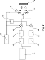
- an electrical measurement signal is generated in a signal generator 11, as in the first known method of an LED 6 converted into an optical signal V1, the optical signal V1 directed to a dye 8, the reflected optical signal from the dye converted in the photodiode 10 into the electrical measurement signal V2 and this processed by means of an analog lock-in amplifier.
- the lock-in amplifier comprises a phase shifter 14 and two analog mixers or multipliers 16.
- the low-frequency components of the measurement signal filtered by a low-pass filter 18 are detected by an analog-to-digital converter (ADC) 12 and evaluated in a control device 2.
- ADC analog-to-digital converter
- a disadvantage of this second method is that the properties of the analog mixer are strongly influenced by component drifting.
- sensors with built-in electronics which are used in process measurement in an extended temperature range and must withstand long operating times without recalibration, such a component driving is not acceptable.
- the use of such sensors in zones with increased risk of explosion due to the high energy consumption is not possible.
- the U.S. Patent 8,078,246 discloses a sensor for pulse oximetry, in which the electrical measurement signal converted by a photodiode is supplied to an input amplifier and is subsequently distributed to a number of N measurement channels which respectively process different wavelengths of the amplified measurement signal.
- Each measuring channel comprises an analog switch, a low-pass filter and an analog-to-digital converter, and the output signals of the N measuring channels are evaluated in a control device.
- the problem mentioned in relation to the first known method is that the signal evaluation per measuring channel is only accurate if the analog-to-digital converter has a sufficiently high resolution and thus a correspondingly high oversampling. The above difficulties therefore also occur in connection with the US 8,078,246 on.
- the invention relates to a device for measuring a periodic signal having a first control device for generating a periodic electrical input signal of the period T, a light source for generating a directed to a measurement object optical input signal from the electrical input signal of the period T, an optical receiver for detecting and converting the signal reflected by the measurement object corresponding to the phase-in and amplitude-changed input optical signal is provided to an electrical measurement signal of period T, and a plurality of measurement channels configured in parallel between the optical receiver and a second control device, each connected in series to a switching element, a filter element and an analog-to-digital converter, wherein the second control device is suitable for evaluating the measurement signals from the plurality of measurement channels.
- the device according to the invention is characterized in that the electrical measuring signal is applied to the plurality of measuring channels, the first control device is connected to the plurality of switching elements and configured to switch on the switching elements for different time intervals in such a way that the electrical measuring signal is repeated at the same time is tapped off for a long time intervals per measurement channel, so that the time segments in each of the measurement channels do not overlap and the analog-to-digital converters have a maximum sampling rate less than 2 ⁇ 1 T respectively.
- the corresponding individual measurement signals can be acquired by slow, economical analog-to-digital converters in subsampling, ie below the Nyquist-Shannon sampling rate.
- the measurement signals detected in the different time intervals can be combined in the second control device and thus the entire measurement signal can be exactly recorded and processed.
- power consumption is significantly less than over-sampling in a single or multiple analog-to-digital converters, also because the switching elements have very low power consumption. Due to the lower power consumption results in a lower self-heating of the entire measuring device, and thus a higher integration density of the components is possible. Moreover, no Inlet drift due to self-heating expected, allowing the device immediately ready for use is. In addition, the low power consumption allows use in potentially explosive environments.
- the electrical input signal is designed as a rectangular signal.
- the received luminescence signal essentially has a sawtooth shape, which can be processed particularly simply and accurately by the plurality of measuring channels of the device according to the invention.
- the filter element is designed as a low pass.
- low pass filters can be constructed of passive analog devices that are cheap and readily available. Due to the low-pass filtering, an integration of the measuring signal in the respective measuring channel is carried out, i. H. an averaging takes place.
- the switching elements in each of the plurality of measurement channels are designed as CMOS switches.
- CMOS switches Such switches in CMOS technology are reliable, simple and inexpensive available and thus particularly well suited for the device according to the invention.
- the first control device is connected to the second control device and synchronized.
- the signal processing can be improved as a whole, because in particular the exact times of the transmission of the periodic measurement signal and the timing of the circuit of the switching elements can be processed directly.
- an integrated circuit has the first control device, the second control device and the plurality of analog-to-digital converters of the plurality of measurement channels.
- Such an integrated circuit may for example be a microcontroller designed for this purpose. Due to the not too complex functionality of the individual components such a microcontroller is relatively simple and available at an acceptable cost.
- the first control device has a pulse width modulation (PWM) generator.
- PWM pulse width modulation
- time intervals in each of the plurality of measurement channels do not overlap.
- time intervals in each of the Plurality of measuring channels are the same length. In principle, the processing in each of the measuring channels is identical.
- the time intervals in each of the plurality of measurement channels correspond to their period T of the electrical input signal.
- T the period of the electrical input signal.
- the electrical input signal is designed as a rectangular signal, and preferably the first control device is synchronized with the second control device.
- the maximum sampling rate ⁇ 2 ⁇ 1 T is. Due to this low sampling rate, which is sub-sampled below the maximum sample rate according to the Nyquist-Shannon sampling theorem. This significantly reduces the requirements for the analog-to-digital converters and reduces their power consumption and accordingly the heating of the component in operation.
- the resources of a corresponding electronic circuit in particular that of a modern microcontroller, can be used more efficiently.
- ADC analog-to-digital converters
- Fig. 3 shows a schematic representation of a preferred embodiment of the inventive device for measuring a periodic signal.
- a first controller 3 generates a periodic electrical signal V1 having a period T which is converted into an optical signal in an LED 6 or equivalent light source.
- the optical signal is directed by the LED 6 to a dye 8, wherein instead of the dye 8 used in the present embodiment, another object to be measured can be used.
- the light reflected by the dye 8 is called an optical measurement signal and directed to a photodiode 10. There it is converted into an electrical measurement signal V2.
- the electrical measurement signal V2 is taken from four essentially identically constructed measurement channels.
- Each measuring channel has a switching element 7, a low-pass filter 9 and an analog-to-digital converter (ADC) 13, each switching element 7 being connected to the first control device 2 and the output of each ADC 13 to a second control device 15.
- ADC analog-to-digital converter
- the number of measuring channels can also be less than or greater than four in a modification of the present embodiment. The following applies: the higher the number of measuring channels, the more accurate the evaluation of the electrical measuring signal V2.
- the switching elements 7 may be formed as analog switches or as CMOS switches, which are connected for example by a PWM generator in the first control device 3.
- the electrical measurement signal V2 which has a period that corresponds to that of the electrical signal V1 is repeated in equal length, disjoint Periods tapped, in such a way that the same time period of each period T is processed by the same measurement channel.
- each switching element 7 which represents a periodically recurring section of the electrical measurement signal V2, wherein the cutouts in each of the measurement channels do not overlap and in the preferred embodiment, the sum of all sections per measurement channel provides the electrical measurement signal V2, one each Low pass 9 supplied, which has the function of an integrator or arithmetic mean value generator and filters out the low-frequency components of the input signal.
- Low-pass filters can be designed as simply constructed passive analog components that are robust and relatively insensitive to temperature.
- each low-pass filter in the lower measuring channel in Fig. 3 labeled V4 is supplied to an analog-to-digital converter (ADC) 13.
- ADC analog-to-digital converter
- sampling rate or sampling frequency which in the preferred embodiment smaller than 2 ⁇ 1 T is, processed, ie digitized. Since the measurement signals are present in each measurement channel only in a small period of the entire period T, comparatively slow and energy-efficient ADCs can be used. Because in the period, where no signal is present, does not need to be scanned. This significantly reduces the sampling rate necessary for adequate acquisition, and thus much less complex and complex ADCs can be used which have significantly reduced power consumption and heat generation.
- the output signals of each of the ADCs 13 from each of the four measurement channels are evaluated and processed, the differences in phase and amplitude of the composite measurement signal with the electrical input signal being a measure of e.g. for the oxygen concentration in the dye 8 are.
- Fig. 4 schematically shows the waveform of the electrical input signal V1, the electrical measurement signal V2 and exemplary of a measuring channel, the output signal V3 of the switching element 7 and the output signal V4 of the low-pass filter 9.
- the electrical input signal V1 is a rectangular signal with a period T
- the electrical measurement signal or received luminescence signal V2 is formed like a sawtooth.
- the output signal V3 of the switching element 7 describes only a portion of the electrical measurement signal V2, in this case part of the rising edge, and the output signal V4 of the low-pass filter is the integrated measurement signal V3.
- a device or a method for measuring a periodic signal which has a relatively low power consumption and self-heating, simple and inexpensive components, ensures an efficient and accurate measurement and particularly well suited for use in potentially explosive environments.
Landscapes
- Physics & Mathematics (AREA)
- Spectroscopy & Molecular Physics (AREA)
- General Physics & Mathematics (AREA)
- Life Sciences & Earth Sciences (AREA)
- Health & Medical Sciences (AREA)
- Heart & Thoracic Surgery (AREA)
- Molecular Biology (AREA)
- Pathology (AREA)
- Engineering & Computer Science (AREA)
- Biomedical Technology (AREA)
- Optics & Photonics (AREA)
- Medical Informatics (AREA)
- Biophysics (AREA)
- Surgery (AREA)
- Animal Behavior & Ethology (AREA)
- General Health & Medical Sciences (AREA)
- Public Health (AREA)
- Veterinary Medicine (AREA)
- Analogue/Digital Conversion (AREA)
- Investigating Or Analysing Materials By Optical Means (AREA)
Description
Die vorliegende Erfindung betrifft das Gebiet der Prozessmesstechnik und -analytik und insbesondere eine Vorrichtung und ein Verfahren zur Messung eines periodischen Signals.The present invention relates to the field of process metrology and analytics, and more particularly to an apparatus and method for measuring a periodic signal.
In Sensoren der Prozessmesstechnik bzw. -analytik werden immer häufiger optische Messverfahren eingesetzt, bei welchen sich die Amplitude und/oder die Phasenlage eines optischen Signals nach Auftreffen auf ein Messobjekt ändern und das veränderte Signal von einem optischen Sensor erfasst wird. Ein Anwendungsbeispiel für ein derartiges optisches Messverfahren ist die Messung des Sauerstoffgehalts bzw. der Sauerstoffsättigung einer Flüssigkeit oder eines Stoffs, wobei zum Beispiel ein Farbstoff mittels eines Lichtsignals einer vorbestimmten Wellenlänge, Amplitude und Phasenlage beleuchtet wird und das vom Farbstoff reflektierte Lumineszenzlicht analysiert wird. Ändert sich die Sauerstoffkonzentration in dem Farbstoff, dann ändert sich auch die Abklingzeit der Lumineszenz und somit die Amplitude und Phasenlage des empfangenen optischen Signals. Bei entsprechender Kalibrierung sind damit Amplitude und Phase des empfangenen optischen Signals ein Maß für die Sauerstoffkonzentration.Optical sensors are increasingly being used in sensors of process measuring technology or analysis, in which the amplitude and / or the phase position of an optical signal change after impact with a measured object and the changed signal is detected by an optical sensor. An example of application of such an optical measuring method is the measurement of the oxygen content or the oxygen saturation of a liquid or a substance, wherein, for example, a dye is illuminated by means of a light signal of a predetermined wavelength, amplitude and phase position and the luminescence light reflected by the dye is analyzed. When the concentration of oxygen in the dye changes, the luminescence decay time and thus the amplitude and phase of the received optical signal also change. With appropriate calibration, the amplitude and phase of the received optical signal are a measure of the oxygen concentration.
Im Stand der Technik werden zur Erfassung der optischen Signale in Sensoren der Prozessmesstechnik bzw. -analytik heute im Wesentlichen zwei Verfahren verwendet.In the prior art, essentially two methods are used today for detecting the optical signals in sensors of process measurement technology or analytics.
Beim ersten Verfahren, dessen Vorrichtung bzw. Signalverlauf schematisch in den
Bei einem zweiten bekannten Messverfahren, für das in
Nachteilig an diesem zweiten Verfahren ist, dass die Eigenschaften des analogen Mischers stark durch Bauteildriften beeinflusst werden. Bei Sensoren mit eingebauter Elektronik, die in der Prozessmesstechnik in einem erweiterten Temperaturbereich eingesetzt werden und lange Betriebszeiten ohne Neukalibrierung überstehen müssen, ist ein derartiges Bauteildriften jedoch nicht akzeptabel. Insbesondere ist der Einsatz von derartigen Sensoren in Zonen mit erhöhter Explosionsgefahr aufgrund der hohen Energieaufnahme nicht möglich.A disadvantage of this second method is that the properties of the analog mixer are strongly influenced by component drifting. For sensors with built-in electronics, which are used in process measurement in an extended temperature range and must withstand long operating times without recalibration, such a component driving is not acceptable. In particular, the use of such sensors in zones with increased risk of explosion due to the high energy consumption is not possible.
Das
Es ist daher die Aufgabe der vorliegenden Erfindung, eine Vorrichtung und ein Verfahren zur Messung eines periodischen Signals bereitzustellen, die bzw. das die Nachteile des Standes der Technik überwindet, eine relativ geringe Leistungsaufnahme und damit Eigenerwärmung aufweist, einfache und günstige Bauelemente enthält und eine effiziente und genaue Messung gewährleistet.It is therefore the object of the present invention to provide a device and a method for measuring a periodic signal, which overcomes the disadvantages of the prior art, a relatively low power consumption and thus self-heating contains simple and inexpensive components and ensures efficient and accurate measurement.
Diese Aufgabe wird durch den Gegenstand der unabhängigen Ansprüche 1 und 8 gelöst. Vorteilhafte Ausführungsformen sind Gegenstand der abhängigen Ansprüche.This object is solved by the subject matter of
Erfindungsgemäß wird eine Vorrichtung zur Messung eines periodischen Signals mit einer ersten Steuereinrichtung zur Erzeugung eines periodischen elektrischen Eingangssignals der Periode T, einer Lichtquelle zur Erzeugung eines auf ein Messobjekt gerichteten optischen Eingangssignals aus dem elektrischen Eingangssignal der Periode T, einem optischen Empfänger zur Erfassung und Umwandlung des von dem Messobjekt reflektierten Signals, das dem in Phase und Amplitude veränderten optischen Eingangssignal entspricht, in ein elektrisches Messsignal der Periode T, und einer Mehrzahl von parallel zwischen dem optischen Empfänger und einer zweiten Steuereinrichtung gestalteten Messkanälen bereitgestellt, die jeweils in Reihe geschaltet ein Schaltelement, ein Filterelement und einen Analog-Digital-Wandler aufweisen, wobei die zweite Steuereinrichtung zur Auswertung der Messsignale von der Mehrzahl der Messkanäle geeignet ist. Die erfindungsgemäße Vorrichtung zeichnet sich dadurch aus, dass an der Mehrzahl von Messkanälen jeweils das elektrische Messsignal anliegt, die erste Steuereinrichtung mit der Mehrzahl von Schaltelementen verbunden und dazu eingerichtet ist, die Schaltelemente für jeweils unterschiedliche Zeitintervalle derart anzuschalten, dass das elektrische Messsignal wiederholt in gleich langen, pro Messkanal disjunkten Zeitabschnitten abgegriffen wird, so dass sich die Zeitabschnitte in jedem der Messkanäle nicht überlappen und die Analog-Digital-Wandler eine maximale Abtastrate kleiner als ![]()
![]()
Durch das "Aufteilen" des elektrischen Messsignals in die Mehrzahl von Messkanälen können die entsprechenden einzelnen Messsignale von langsamen, sparsamen Analog-Digital-Wandlern in Unterabtastung, d.h. unterhalb der Nyquist-Shannon-Abtastrate, erfasst werden. Gleichzeitig können die in den unterschiedlichen Zeitintervallen erfassten Messsignale in der zweiten Steuereinrichtung zusammengefasst und damit das gesamte Messsignal exakt erfasst und verarbeitet werden. Im Gegensatz zu den Vorrichtungen und Verfahren des Standes der Technik ist die Leistungsaufnahme erheblich geringer als bei einer Überabtastung in einem einzigen oder auch mehreren Analog-Digital-Wandlern, auch weil die Schaltelemente eine sehr geringe Leistungsaufnahme aufweisen. Durch die geringere Leistungsaufnahme ergibt sich eine geringere Eigenerwärmung der gesamten Messvorrichtung, und damit ist eine höhere Integrationsdichte der Bauelemente möglich. Zudem ist keine Einlaufdrift durch die Eigenerwärmung zu erwarten, so dass die Vorrichtung sofort einsatzbereit ist. Darüber hinaus ermöglicht die geringe Leistungsaufnahme den Einsatz in explosionsgefährdeten Umgebungen.By "splitting" the electrical measurement signal into the plurality of measurement channels, the corresponding individual measurement signals can be acquired by slow, economical analog-to-digital converters in subsampling, ie below the Nyquist-Shannon sampling rate. At the same time, the measurement signals detected in the different time intervals can be combined in the second control device and thus the entire measurement signal can be exactly recorded and processed. In contrast to prior art devices and methods, power consumption is significantly less than over-sampling in a single or multiple analog-to-digital converters, also because the switching elements have very low power consumption. Due to the lower power consumption results in a lower self-heating of the entire measuring device, and thus a higher integration density of the components is possible. Moreover, no Inlet drift due to self-heating expected, allowing the device immediately ready for use is. In addition, the low power consumption allows use in potentially explosive environments.
Mit besonderem Vorteil ist das elektrische Eingangssignal als Rechtecksignal ausgebildet. Dadurch weist das empfangene Lumineszenzsignal im Wesentlichen eine Sägezahnform auf, die durch die Mehrzahl von Messkanälen der erfindungsgemäßen Vorrichtung besonders einfach und genau verarbeitet werden kann.With particular advantage, the electrical input signal is designed as a rectangular signal. As a result, the received luminescence signal essentially has a sawtooth shape, which can be processed particularly simply and accurately by the plurality of measuring channels of the device according to the invention.
Mit weiterem Vorteil ist das Filterelement als Tiefpass ausgebildet. Tiefpässe können beispielsweise aus passiven analogen Bauelementen aufgebaut sein, die günstig und einfach verfügbar sind. Durch die Tiefpassfilterung wird eine Integration des Messsignals in dem jeweiligen Messkanal vorgenommen, d. h. es findet eine Mittelwertbildung statt.With further advantage, the filter element is designed as a low pass. For example, low pass filters can be constructed of passive analog devices that are cheap and readily available. Due to the low-pass filtering, an integration of the measuring signal in the respective measuring channel is carried out, i. H. an averaging takes place.
Bevorzugt sind die Schaltelemente in jedem der Mehrzahl von Messkanälen als CMOS-Schalter bzw. -Umschalter ausgebildet. Derartige Schalter in CMOS-Technik sind zuverlässig, einfach aufgebaut und preisgünstig verfügbar und damit für die erfindungsgemäße Vorrichtung besonders gut geeignet.Preferably, the switching elements in each of the plurality of measurement channels are designed as CMOS switches. Such switches in CMOS technology are reliable, simple and inexpensive available and thus particularly well suited for the device according to the invention.
Mit weiterem Vorteil ist die erste Steuereinrichtung mit der zweiten Steuereinrichtung verbunden und synchronisiert. Damit kann die Signalverarbeitung insgesamt verbessert werden, weil insbesondere die genauen Zeitpunkte der Aussendung des periodischen Messsignals und die Zeitpunkte der Schaltung der Schaltelemente direkt verarbeitet werden können.With further advantage, the first control device is connected to the second control device and synchronized. Thus, the signal processing can be improved as a whole, because in particular the exact times of the transmission of the periodic measurement signal and the timing of the circuit of the switching elements can be processed directly.
Besonders bevorzugt ist es, wenn ein integrierter Schaltkreis die erste Steuereinrichtung, die zweite Steuereinrichtung sowie die Mehrzahl der Analog-Digital-Wandler der Mehrzahl von Messkanälen aufweist. Ein derartiger integrierter Schaltkreis kann beispielsweise ein dafür konstruierter Mikrocontroller sein. Aufgrund der nicht zu komplexen Funktionalität der einzelnen Bauelemente ist ein solcher Mikrocontroller relativ einfach aufgebaut und zu akzeptablen Kosten verfügbar.It is particularly preferred if an integrated circuit has the first control device, the second control device and the plurality of analog-to-digital converters of the plurality of measurement channels. Such an integrated circuit may for example be a microcontroller designed for this purpose. Due to the not too complex functionality of the individual components such a microcontroller is relatively simple and available at an acceptable cost.
Mit weiterem Vorteil weist die erste Steuereinrichtung einen Pulsweitenmodulations- (PWM) Generator auf. Damit können durch eine einfache digitale Logik sowohl das Messsignal erzeugt als auch die Abtast- bzw. Schaltelemente angesteuert werden. In dem Mikrocontroller selbst, in den der PWM-Generator integriert sein kann, ist selbst kein Rechenaufwand notwendig, um die entsprechenden Signale zu erzeugen. Der Einsatz eines PWM-Generators ist deshalb ressourcen- und energiesparend.With further advantage, the first control device has a pulse width modulation (PWM) generator. This can be generated by a simple digital logic both the measurement signal and the sampling or switching elements are controlled. In the microcontroller itself, in which the PWM generator can be integrated, is itself no computational effort necessary to generate the appropriate signals. The use of a PWM generator is therefore resource and energy saving.
Weiterhin erfindungsgemäß ist ein Verfahren zur Messung eines periodischen Signals wie im Anspruch 8 definiert.Furthermore, according to the invention, a method for measuring a periodic signal as defined in
Die in Bezug auf die oben genannte Vorrichtung erwähnten Vorteile gelten auch für das erfindungsgemäße Verfahren. Im Vergleich zum erwähnten Stand der Technik (erstes Verfahren) kann man sich vorstellen, dass bei dem erfindungsgemäßen Verfahren ebenso viele Messkanäle verwendet werden, wie beim ersten Verfahren des Stands der Technik Stützpunkte innerhalb einer Periode des gesendeten Signals vorhanden sind. Es wird jedoch nicht nur das Signal an einem einzigen Punkt erfasst, sondern derselbe Bereich des elektrischen Messsignals wird über eine hohe Anzahl von Perioden integriert und damit zuverlässig ein Messmittelwert gebildet. Trotz der höheren Anzahl von relativ einfachen und preisgünstigen Bauelemente kann bei dem erfindungsgemäßen Verfahren und der erfindungsgemäßen Vorrichtung auf aufwändige und teure Analog-Digital-Wandler und besonders leistungsfähige Prozessoren verzichtet werden. Dadurch ergibt sich eine Kostenersparnis ohne bei der Messgenauigkeit und Zuverlässigkeit Abstriche machen zu müssen.The advantages mentioned in relation to the above-mentioned device also apply to the method according to the invention. Compared to the mentioned prior art (first method), it can be imagined that in the method according to the invention as many measuring channels are used as there are interpolation points within a period of the transmitted signal in the first method of the prior art. However, not only the signal is detected at a single point, but the same area of the electrical measurement signal is integrated over a high number of periods, thus reliably forming a measurement average. Despite the higher number of relatively simple and inexpensive components can be dispensed in the inventive method and apparatus according to the invention complex and expensive analog-to-digital converters and particularly powerful processors. This results in a cost savings without having to compromise on measurement accuracy and reliability.
Bevorzugt ist es, wenn sich die Zeitintervalle in jedem der Mehrzahl von Messkanälen nicht überlappen. Insbesondere ist es auch von Vorteil, wenn die Zeitintervalle in jedem der Mehrzahl von Messkanälen gleich lang sind. Damit ist die Verarbeitung in jedem der Messkanäle prinzipiell identisch.It is preferable if the time intervals in each of the plurality of measurement channels do not overlap. In particular, it is also advantageous if the time intervals in each of the Plurality of measuring channels are the same length. In principle, the processing in each of the measuring channels is identical.
Mit besonderem Vorteil entsprechen die Zeitintervalle in jedem der Mehrzahl von Messkanälen deren Periode T des elektrischen Eingangssignals. Damit wird in jedem Messkanal genau derselbe sich wiederholende Zeitabschnitt über die gesamte Messdauer abgetastet, integriert und analog-digital-gewandelt. Durch Zusammensetzen der einzelnen Ausgangssignale der Mehrzahl von Messkanälen in der zweiten Steuereinrichtung lässt sich so die Amplitude und auf die Phasenlage des Messsignals auf einfache Weise bestimmen.With particular advantage, the time intervals in each of the plurality of measurement channels correspond to their period T of the electrical input signal. Thus, in each measurement channel, exactly the same repetitive time period is sampled over the entire measurement period, integrated and converted analog-to-digital. By combining the individual output signals of the plurality of measuring channels in the second control device, the amplitude and the phase position of the measuring signal can thus be determined in a simple manner.
Mit weiterem Vorteil ist das elektrische Eingangssignal als Rechtecksignal ausgebildet, und bevorzugt ist die erste Steuereinrichtung mit der zweiten Steuereinrichtung synchronisiert.With further advantage, the electrical input signal is designed as a rectangular signal, and preferably the first control device is synchronized with the second control device.
Besonders bevorzugt ist, wenn in jedem Analog-Digital-Wandler der Mehrzahl von Messkanälen die maximale Abtastrate ![]()
![]()
Durch die erfindungsgemäße Vorrichtung bzw. das erfindungsgemäße Verfahren lassen sich die Ressourcen einer entsprechenden elektronischen Schaltung, insbesondere die eines modernen Mikrocontrollers, effizienter nutzen. Da die Energieaufnahme von Analog-Digital-Wandlern (ADC) üblicherweise mit der Auflösung, das heißt der maximalen Abtastrate, steigt, sind bei der vorliegenden Vorrichtung lediglich Analog-Digital-Wandler mit sehr geringer Energieaufnahme erforderlich, ohne dabei auf eine genügend hohe Auflösung des Messsignals zu verzichten.By means of the device according to the invention or the method according to the invention, the resources of a corresponding electronic circuit, in particular that of a modern microcontroller, can be used more efficiently. Since the power consumption of analog-to-digital converters (ADC) usually with the resolution, that is, the maximum sampling rate increases, only analog-to-digital converters with very low power consumption are required in the present device, without a sufficiently high resolution of the To dispense with measuring signal.
Die vorliegende Erfindung wird nachfolgend anhand von bevorzugten Ausführungsformen unter Bezugnahme auf die Zeichnungen beschrieben, in denen:
- Fig. 1a
- eine schematische Darstellung einer ersten optischen Messvorrichtung des Standes der Technik ist;
- Fig. 1b
- eine Kurvendarstellung der Messsignale der in
Fig. 1a dargestellten optischen Messvorrichtung ist; - Fig. 2
- eine schematische Darstellung einer zweiten optischen Messvorrichtung des Standes der Technik ist;
- Fig. 3
- eine schematische Darstellung einer bevorzugten Ausführungsform einer erfindungsgemäßen Vorrichtung zur Messung eines periodischen Signals ist; und
- Fig. 4
- eine Kurvendarstellung der Messsignale der in
Fig. 3 dargestellten Vorrichtung ist.
- Fig. 1a
- is a schematic representation of a first optical measuring device of the prior art;
- Fig. 1b
- a graph of the measurement signals of in
Fig. 1a is shown optical measuring device; - Fig. 2
- is a schematic representation of a second optical measuring device of the prior art;
- Fig. 3
- is a schematic representation of a preferred embodiment of a device according to the invention for measuring a periodic signal; and
- Fig. 4
- a graph of the measurement signals of in
Fig. 3 is shown device.
Das elektrische Messsignal V2 wird von vier im Wesentlichen gleich aufgebauten Messkanälen abgenommen. Jeder Messkanal weist ein Schaltelement 7, einen Tiefpass 9 und einen Analog-Digital-Wandler (ADC)13 auf, wobei jedes Schaltelement 7 mit der ersten Steuereinrichtung 2 und der Ausgang jedes ADC 13 mit einer zweiten Steuereinrichtung 15 verbunden ist. Die Anzahl der Messkanäle kann in Abänderung des vorliegenden Ausführungsbeispiels auch kleiner oder größer als vier sein. Dabei gilt: je höher die Anzahl der Messkanäle, desto genauer die Auswertung des elektrischen Messsignals V2.The electrical measurement signal V2 is taken from four essentially identically constructed measurement channels. Each measuring channel has a switching element 7, a low-
Die Schaltelemente 7 können als Analogschalter oder auch als CMOS-Schalter ausgebildet sein, die beispielsweise von einem PWM-Generator in der ersten Steuereinrichtung 3 geschaltet werden. Dabei wird das elektrische Messsignal V2, das eine Periodendauer aufweist, die der des elektrischen Signals V1 entspricht, wiederholt in gleich langen, disjunkten Zeitabschnitten abgegriffen, und zwar derart, dass derselbe Zeitabschnitt jeder Periode T von demselben Messkanal verarbeitet wird. Eine detaillierte Erläuterung folgt unten unter Bezugnahme auf
Das Ausgangssignal, im unteren Messkanal in
Das Ausgangssignal jedes Tiefpassfilters, im unteren Messkanal in ![]()
![]()
In der zweiten Steuereinrichtung 15 werden die Ausgangssignale jedes der ADCs 13 aus jedem der vier Messkanäle ausgewertet und verarbeitet, wobei die Unterschiede in Phasenlage und Amplitude des zusammengesetzten Messsignals mit dem elektrischen Eingangssignal ein Maß z.B. für die Sauerstoffkonzentration im Farbstoff 8 sind.In the
Mit der erfindungsgemäßen Gegenstand wird eine Vorrichtung bzw. ein Verfahren zur Messung eines periodischen Signals bereitgestellt, die bzw. das eine relativ geringe Leistungsaufnahme und damit Eigenerwärmung aufweist, einfache und günstige Bauelemente enthält, eine effiziente und genaue Messung gewährleistet und besonders gut geeignet für den Einsatz in explosionsgefährdeten Umgebungen ist.With the object according to the invention, a device or a method for measuring a periodic signal is provided, which has a relatively low power consumption and self-heating, simple and inexpensive components, ensures an efficient and accurate measurement and particularly well suited for use in potentially explosive environments.
Claims (11)
- Sensor (1) for process measuring technology for measuring a periodic signal with
a first control device (3) for generating a periodic electrical input signal (V1) of period T,
a light source (6) for generating an optical input signal directed to an object (8) to be measured from the electrical input signal (V1) of period T,
an optical receiver (10) for detecting and converting the signal, which is reflected from the measurement object and corresponds to the optical input signal modified in phase and amplitude, into an electrical measurement signal (V2) of period T,
and
a plurality of measuring channels which are switched in parallel between the optical receiver (10) and a second control device (15) and which comprise a switching element (7), a filter element (9) and an analog-digital converter (13) switched in series, wherein the second control device (15) is suitable for evaluating the measurement signals from the plurality of measuring channels,
wherein the electrical measurement signal (V2) contacts each of the plurality of measuring channels,
wherein the first control device (3) is connected to the plurality of switching elements (7) and is set up to switch on the switching elements (7) for the respective different time intervals in such a way that the electrical measurement signal (V2) is repeatedly picked up in equal length time sections disjoined per measuring channel, so that the time sections in each of the measuring channels do not overlap, and
wherein the analog-digital converters (13) have a maximum sampling rate lower than
- Sensor (1) according to claim 1, characterized in that the electrical input signal is configured as a square wave signal.
- Sensor (1) according to one of the preceding claims, characterized in that the filter element is a low pass filter (9).
- Sensor (1) according to one of the preceding claims, characterized in that the switching element (7) in each of the plurality of measuring channels is configured as a CMOS switch or changeover switch.
- Sensor (1) according to one of the preceding claims, characterized in that the first control device (3) is connected to and synchronized with the second control device (15).
- Sensor (1) according to one of the preceding claims, characterized in that an integrated switching circuit comprises the first control device (3), the second control device (15) as well as the plurality of analog-digital converters (13).
- Sensor (1) according to one of the preceding claims, characterized in that the first control device (3) has a pulse width modulation (PWM) generator.
- Method for measuring a periodic measurement signal with the following steps:sending an optical input signal of a light source (6) based on an electrical input signal (V1) of the period T to an object (8) to be measured,receiving and converting an optical measurement signal, which corresponds to the optical input signal which is modified in phase and amplitude, in an optical receiver (10) into an electrical measurement signal (V2) of period T,picking up the electrical measurement signal (V2) with each of a plurality of parallel-switched measuring channels which each have a switching element (7), a low pass filter (9) and an analog-digital converter (13) switched in series,wherein the same electrical measurement signal (V2) is processed in each of the plurality of measuring channels,wherein the electrical measurement signal (V2) is picked up in each of the plurality of measuring channels in respective disjoined periodically recurring time intervals in such a way that the time sections in each of the measuring channels do not overlap, wherein a first control device (3) actuates the switching elements (7) in each of the plurality of measuring channels,wherein the electrical measurement signal of each time interval in each of the plurality of measuring channels is integrated in the low pass filter (9), converted in the analog-digital converter (13) and evaluated in a second control device (15), andwherein in each analog-digital converter (13) of the plurality of measuring channels the maximum sampling rate is less than

- Method according to claim 8, characterized in that the time intervals in each of the plurality of measuring channels are of the same length.
- Method according to one of claims 8 to 9, characterized in that the electrical input signal (V1) is configured as a square wave signal.
- Method according to one of claims 8 to 10, characterized in that the first control device (3) and the second control device (15) are synchronized with one another.
Applications Claiming Priority (2)
| Application Number | Priority Date | Filing Date | Title |
|---|---|---|---|
| DE102012113008.6A DE102012113008A1 (en) | 2012-12-21 | 2012-12-21 | Apparatus and method for measuring a periodic signal |
| PCT/EP2013/072088 WO2014095128A1 (en) | 2012-12-21 | 2013-10-22 | Apparatus and method for measuring a periodic signal |
Publications (2)
| Publication Number | Publication Date |
|---|---|
| EP2936091A1 EP2936091A1 (en) | 2015-10-28 |
| EP2936091B1 true EP2936091B1 (en) | 2019-04-10 |
Family
ID=49578259
Family Applications (1)
| Application Number | Title | Priority Date | Filing Date |
|---|---|---|---|
| EP13789501.7A Active EP2936091B1 (en) | 2012-12-21 | 2013-10-22 | Apparatus and method for measuring a periodic signal |
Country Status (5)
| Country | Link |
|---|---|
| US (1) | US9810577B2 (en) |
| EP (1) | EP2936091B1 (en) |
| CN (1) | CN104870954B (en) |
| DE (1) | DE102012113008A1 (en) |
| WO (1) | WO2014095128A1 (en) |
Family Cites Families (18)
| Publication number | Priority date | Publication date | Assignee | Title |
|---|---|---|---|---|
| WO2001078593A1 (en) * | 2000-04-17 | 2001-10-25 | Nellcor Puritan Bennett Incorporated | Pulse oximeter sensor with piece-wise function |
| US7564866B2 (en) * | 2000-07-21 | 2009-07-21 | Broadcom Corporation | Methods and systems for digitally processing optical data signals |
| US6606510B2 (en) * | 2000-08-31 | 2003-08-12 | Mallinckrodt Inc. | Oximeter sensor with digital memory encoding patient data |
| EP1237128B1 (en) * | 2001-03-01 | 2012-08-01 | Sicpa Holding Sa | Improved luminescence characteristics detector |
| US7072267B2 (en) * | 2001-11-26 | 2006-07-04 | William Monford Wood | Image and data storage by focused ion beam recordation and method thereof |
| US7142142B2 (en) * | 2004-02-25 | 2006-11-28 | Nelicor Puritan Bennett, Inc. | Multi-bit ADC with sigma-delta modulation |
| JP3935897B2 (en) * | 2004-06-15 | 2007-06-27 | 北陽電機株式会社 | Lightwave ranging device |
| JP4494160B2 (en) * | 2004-10-14 | 2010-06-30 | 株式会社トプコン | Optical image measuring device |
| US7486977B2 (en) * | 2005-10-27 | 2009-02-03 | Smiths Medical Pm, Inc. | Single use pulse oximeter |
| DE102006030530A1 (en) * | 2006-07-01 | 2008-01-03 | Carl Zeiss Microimaging Gmbh | Method and device for detecting light signals |
| US20080129369A1 (en) * | 2006-10-26 | 2008-06-05 | Dusan Ivancevic | Current multiplexing circuit for optical power monitoring |
| GB2458908B (en) * | 2008-04-01 | 2010-02-24 | Michael Frank Castle | Low power signal processor |
| US7804328B2 (en) * | 2008-06-23 | 2010-09-28 | Texas Instruments Incorporated | Source/emitter follower buffer driving a switching load and having improved linearity |
| US8401608B2 (en) * | 2009-09-30 | 2013-03-19 | Covidien Lp | Method of analyzing photon density waves in a medical monitor |
| CN102062853A (en) * | 2009-11-16 | 2011-05-18 | 英属维京群岛商齐治股份有限公司 | Optical position detection device and method |
| KR101635108B1 (en) * | 2009-12-09 | 2016-07-08 | 삼성전자주식회사 | Method and apparatus for image scanning |
| US8558725B2 (en) * | 2010-10-27 | 2013-10-15 | Intersil Americas Inc. | Robust gain and phase calibration method for a time-interleaved analog-to-digital converter |
| US8704691B2 (en) * | 2012-09-07 | 2014-04-22 | Lsi Corporation | Track-and-hold circuit for analog-to-digital converter with switched capacitor coupling of amplifier stage |
-
2012
- 2012-12-21 DE DE102012113008.6A patent/DE102012113008A1/en not_active Withdrawn
-
2013
- 2013-10-22 EP EP13789501.7A patent/EP2936091B1/en active Active
- 2013-10-22 US US14/654,217 patent/US9810577B2/en active Active
- 2013-10-22 WO PCT/EP2013/072088 patent/WO2014095128A1/en not_active Ceased
- 2013-10-22 CN CN201380067517.6A patent/CN104870954B/en active Active
Non-Patent Citations (1)
| Title |
|---|
| None * |
Also Published As
| Publication number | Publication date |
|---|---|
| US20150300880A1 (en) | 2015-10-22 |
| US9810577B2 (en) | 2017-11-07 |
| CN104870954A (en) | 2015-08-26 |
| EP2936091A1 (en) | 2015-10-28 |
| DE102012113008A1 (en) | 2014-06-26 |
| CN104870954B (en) | 2017-06-06 |
| WO2014095128A1 (en) | 2014-06-26 |
Similar Documents
| Publication | Publication Date | Title |
|---|---|---|
| DE102008023535B4 (en) | Electronic device and method for evaluating a variable capacity | |
| EP0632262B1 (en) | Method and device for measuring and evaluating analog photometric signals in an analysing system for test carriers | |
| EP0075767B1 (en) | Method for the determination and evaluation of photometric signals and device for carrying out the method | |
| EP0800059B2 (en) | Method of data transfer in a position measuring device | |
| EP1584905B1 (en) | Electronic device for processing signals | |
| EP2651036A1 (en) | Inductive proximity sensor | |
| EP2087595A1 (en) | Measurement amplification device and method | |
| DE102008023277A1 (en) | converter device | |
| DE3800265A1 (en) | VOLTAGE FREQUENCY CONVERTER AND ITS USE IN A WAVE LEAD TRANSMISSION ARRANGEMENT | |
| DE102007041646B4 (en) | Method for operating an active sensor and active sensor | |
| EP2936091B1 (en) | Apparatus and method for measuring a periodic signal | |
| DE102014113545A1 (en) | Device and method for monitoring a process variable of a medium | |
| DE102014111952A1 (en) | Sensor device for detecting an environment of a motor vehicle, driver assistance system, motor vehicle and method | |
| DE102016005478B3 (en) | Method and device for measuring the lifetime of charge carriers in semiconductors | |
| EP0145698B1 (en) | Optoelectronic length and angle metering method and measuring device to realize this method | |
| EP0378777A2 (en) | Arrangement for converting analog signals into digital signals | |
| DE102017129461B3 (en) | Delta sigma modulator for carrier frequency measurement systems | |
| EP2936119B1 (en) | Optical measuring device | |
| DE19902612A1 (en) | Optoelectronic mixer | |
| DE2952311A1 (en) | analog=digital converter for instrument - uses controllable duty-factor of added AC compensation voltage as analog measure | |
| DE102025115864B3 (en) | Optoelectronic receiver, optoelectronic sensor, use and method for distance measurement using the time-of-flight method | |
| DE102007048727B4 (en) | Sensor device | |
| WO2014147058A2 (en) | Analogue-digital converter and method for generating a digital data stream | |
| DE19536819A1 (en) | DC voltage monitoring device, for railway signalling system where DC voltage is affected by AC voltage | |
| DE102017101261B4 (en) | Digitized rain sensor for measuring the optical reflection properties of an object possibly wetted with liquid for use in motor vehicles |
Legal Events
| Date | Code | Title | Description |
|---|---|---|---|
| PUAI | Public reference made under article 153(3) epc to a published international application that has entered the european phase |
Free format text: ORIGINAL CODE: 0009012 |
|
| 17P | Request for examination filed |
Effective date: 20150625 |
|
| AK | Designated contracting states |
Kind code of ref document: A1 Designated state(s): AL AT BE BG CH CY CZ DE DK EE ES FI FR GB GR HR HU IE IS IT LI LT LU LV MC MK MT NL NO PL PT RO RS SE SI SK SM TR |
|
| AX | Request for extension of the european patent |
Extension state: BA ME |
|
| DAX | Request for extension of the european patent (deleted) | ||
| STAA | Information on the status of an ep patent application or granted ep patent |
Free format text: STATUS: EXAMINATION IS IN PROGRESS |
|
| 17Q | First examination report despatched |
Effective date: 20170627 |
|
| GRAP | Despatch of communication of intention to grant a patent |
Free format text: ORIGINAL CODE: EPIDOSNIGR1 |
|
| STAA | Information on the status of an ep patent application or granted ep patent |
Free format text: STATUS: GRANT OF PATENT IS INTENDED |
|
| INTG | Intention to grant announced |
Effective date: 20181026 |
|
| GRAS | Grant fee paid |
Free format text: ORIGINAL CODE: EPIDOSNIGR3 |
|
| GRAA | (expected) grant |
Free format text: ORIGINAL CODE: 0009210 |
|
| STAA | Information on the status of an ep patent application or granted ep patent |
Free format text: STATUS: THE PATENT HAS BEEN GRANTED |
|
| AK | Designated contracting states |
Kind code of ref document: B1 Designated state(s): AL AT BE BG CH CY CZ DE DK EE ES FI FR GB GR HR HU IE IS IT LI LT LU LV MC MK MT NL NO PL PT RO RS SE SI SK SM TR |
|
| REG | Reference to a national code |
Ref country code: GB Ref legal event code: FG4D Free format text: NOT ENGLISH |
|
| REG | Reference to a national code |
Ref country code: CH Ref legal event code: EP Ref country code: AT Ref legal event code: REF Ref document number: 1119330 Country of ref document: AT Kind code of ref document: T Effective date: 20190415 |
|
| REG | Reference to a national code |
Ref country code: IE Ref legal event code: FG4D Free format text: LANGUAGE OF EP DOCUMENT: GERMAN |
|
| REG | Reference to a national code |
Ref country code: DE Ref legal event code: R096 Ref document number: 502013012624 Country of ref document: DE |
|
| REG | Reference to a national code |
Ref country code: SE Ref legal event code: TRGR |
|
| REG | Reference to a national code |
Ref country code: NL Ref legal event code: MP Effective date: 20190410 |
|
| REG | Reference to a national code |
Ref country code: LT Ref legal event code: MG4D |
|
| PG25 | Lapsed in a contracting state [announced via postgrant information from national office to epo] |
Ref country code: NL Free format text: LAPSE BECAUSE OF FAILURE TO SUBMIT A TRANSLATION OF THE DESCRIPTION OR TO PAY THE FEE WITHIN THE PRESCRIBED TIME-LIMIT Effective date: 20190410 |
|
| PG25 | Lapsed in a contracting state [announced via postgrant information from national office to epo] |
Ref country code: HR Free format text: LAPSE BECAUSE OF FAILURE TO SUBMIT A TRANSLATION OF THE DESCRIPTION OR TO PAY THE FEE WITHIN THE PRESCRIBED TIME-LIMIT Effective date: 20190410 Ref country code: ES Free format text: LAPSE BECAUSE OF FAILURE TO SUBMIT A TRANSLATION OF THE DESCRIPTION OR TO PAY THE FEE WITHIN THE PRESCRIBED TIME-LIMIT Effective date: 20190410 Ref country code: LT Free format text: LAPSE BECAUSE OF FAILURE TO SUBMIT A TRANSLATION OF THE DESCRIPTION OR TO PAY THE FEE WITHIN THE PRESCRIBED TIME-LIMIT Effective date: 20190410 Ref country code: FI Free format text: LAPSE BECAUSE OF FAILURE TO SUBMIT A TRANSLATION OF THE DESCRIPTION OR TO PAY THE FEE WITHIN THE PRESCRIBED TIME-LIMIT Effective date: 20190410 Ref country code: AL Free format text: LAPSE BECAUSE OF FAILURE TO SUBMIT A TRANSLATION OF THE DESCRIPTION OR TO PAY THE FEE WITHIN THE PRESCRIBED TIME-LIMIT Effective date: 20190410 Ref country code: PT Free format text: LAPSE BECAUSE OF FAILURE TO SUBMIT A TRANSLATION OF THE DESCRIPTION OR TO PAY THE FEE WITHIN THE PRESCRIBED TIME-LIMIT Effective date: 20190910 Ref country code: NO Free format text: LAPSE BECAUSE OF FAILURE TO SUBMIT A TRANSLATION OF THE DESCRIPTION OR TO PAY THE FEE WITHIN THE PRESCRIBED TIME-LIMIT Effective date: 20190710 |
|
| PG25 | Lapsed in a contracting state [announced via postgrant information from national office to epo] |
Ref country code: GR Free format text: LAPSE BECAUSE OF FAILURE TO SUBMIT A TRANSLATION OF THE DESCRIPTION OR TO PAY THE FEE WITHIN THE PRESCRIBED TIME-LIMIT Effective date: 20190711 Ref country code: PL Free format text: LAPSE BECAUSE OF FAILURE TO SUBMIT A TRANSLATION OF THE DESCRIPTION OR TO PAY THE FEE WITHIN THE PRESCRIBED TIME-LIMIT Effective date: 20190410 Ref country code: LV Free format text: LAPSE BECAUSE OF FAILURE TO SUBMIT A TRANSLATION OF THE DESCRIPTION OR TO PAY THE FEE WITHIN THE PRESCRIBED TIME-LIMIT Effective date: 20190410 Ref country code: RS Free format text: LAPSE BECAUSE OF FAILURE TO SUBMIT A TRANSLATION OF THE DESCRIPTION OR TO PAY THE FEE WITHIN THE PRESCRIBED TIME-LIMIT Effective date: 20190410 Ref country code: BG Free format text: LAPSE BECAUSE OF FAILURE TO SUBMIT A TRANSLATION OF THE DESCRIPTION OR TO PAY THE FEE WITHIN THE PRESCRIBED TIME-LIMIT Effective date: 20190710 |
|
| PG25 | Lapsed in a contracting state [announced via postgrant information from national office to epo] |
Ref country code: IS Free format text: LAPSE BECAUSE OF FAILURE TO SUBMIT A TRANSLATION OF THE DESCRIPTION OR TO PAY THE FEE WITHIN THE PRESCRIBED TIME-LIMIT Effective date: 20190810 |
|
| REG | Reference to a national code |
Ref country code: DE Ref legal event code: R097 Ref document number: 502013012624 Country of ref document: DE |
|
| PG25 | Lapsed in a contracting state [announced via postgrant information from national office to epo] |
Ref country code: DK Free format text: LAPSE BECAUSE OF FAILURE TO SUBMIT A TRANSLATION OF THE DESCRIPTION OR TO PAY THE FEE WITHIN THE PRESCRIBED TIME-LIMIT Effective date: 20190410 Ref country code: EE Free format text: LAPSE BECAUSE OF FAILURE TO SUBMIT A TRANSLATION OF THE DESCRIPTION OR TO PAY THE FEE WITHIN THE PRESCRIBED TIME-LIMIT Effective date: 20190410 Ref country code: CZ Free format text: LAPSE BECAUSE OF FAILURE TO SUBMIT A TRANSLATION OF THE DESCRIPTION OR TO PAY THE FEE WITHIN THE PRESCRIBED TIME-LIMIT Effective date: 20190410 Ref country code: RO Free format text: LAPSE BECAUSE OF FAILURE TO SUBMIT A TRANSLATION OF THE DESCRIPTION OR TO PAY THE FEE WITHIN THE PRESCRIBED TIME-LIMIT Effective date: 20190410 Ref country code: SK Free format text: LAPSE BECAUSE OF FAILURE TO SUBMIT A TRANSLATION OF THE DESCRIPTION OR TO PAY THE FEE WITHIN THE PRESCRIBED TIME-LIMIT Effective date: 20190410 |
|
| PLBE | No opposition filed within time limit |
Free format text: ORIGINAL CODE: 0009261 |
|
| STAA | Information on the status of an ep patent application or granted ep patent |
Free format text: STATUS: NO OPPOSITION FILED WITHIN TIME LIMIT |
|
| PG25 | Lapsed in a contracting state [announced via postgrant information from national office to epo] |
Ref country code: SM Free format text: LAPSE BECAUSE OF FAILURE TO SUBMIT A TRANSLATION OF THE DESCRIPTION OR TO PAY THE FEE WITHIN THE PRESCRIBED TIME-LIMIT Effective date: 20190410 Ref country code: IT Free format text: LAPSE BECAUSE OF FAILURE TO SUBMIT A TRANSLATION OF THE DESCRIPTION OR TO PAY THE FEE WITHIN THE PRESCRIBED TIME-LIMIT Effective date: 20190410 |
|
| 26N | No opposition filed |
Effective date: 20200113 |
|
| PG25 | Lapsed in a contracting state [announced via postgrant information from national office to epo] |
Ref country code: TR Free format text: LAPSE BECAUSE OF FAILURE TO SUBMIT A TRANSLATION OF THE DESCRIPTION OR TO PAY THE FEE WITHIN THE PRESCRIBED TIME-LIMIT Effective date: 20190410 |
|
| PG25 | Lapsed in a contracting state [announced via postgrant information from national office to epo] |
Ref country code: MC Free format text: LAPSE BECAUSE OF FAILURE TO SUBMIT A TRANSLATION OF THE DESCRIPTION OR TO PAY THE FEE WITHIN THE PRESCRIBED TIME-LIMIT Effective date: 20190410 Ref country code: SI Free format text: LAPSE BECAUSE OF FAILURE TO SUBMIT A TRANSLATION OF THE DESCRIPTION OR TO PAY THE FEE WITHIN THE PRESCRIBED TIME-LIMIT Effective date: 20190410 |
|
| PG25 | Lapsed in a contracting state [announced via postgrant information from national office to epo] |
Ref country code: LU Free format text: LAPSE BECAUSE OF NON-PAYMENT OF DUE FEES Effective date: 20191022 |
|
| REG | Reference to a national code |
Ref country code: BE Ref legal event code: MM Effective date: 20191031 |
|
| PG25 | Lapsed in a contracting state [announced via postgrant information from national office to epo] |
Ref country code: BE Free format text: LAPSE BECAUSE OF NON-PAYMENT OF DUE FEES Effective date: 20191031 |
|
| PG25 | Lapsed in a contracting state [announced via postgrant information from national office to epo] |
Ref country code: IE Free format text: LAPSE BECAUSE OF NON-PAYMENT OF DUE FEES Effective date: 20191022 |
|
| PG25 | Lapsed in a contracting state [announced via postgrant information from national office to epo] |
Ref country code: CY Free format text: LAPSE BECAUSE OF FAILURE TO SUBMIT A TRANSLATION OF THE DESCRIPTION OR TO PAY THE FEE WITHIN THE PRESCRIBED TIME-LIMIT Effective date: 20190410 |
|
| PG25 | Lapsed in a contracting state [announced via postgrant information from national office to epo] |
Ref country code: MT Free format text: LAPSE BECAUSE OF FAILURE TO SUBMIT A TRANSLATION OF THE DESCRIPTION OR TO PAY THE FEE WITHIN THE PRESCRIBED TIME-LIMIT Effective date: 20190410 Ref country code: HU Free format text: LAPSE BECAUSE OF FAILURE TO SUBMIT A TRANSLATION OF THE DESCRIPTION OR TO PAY THE FEE WITHIN THE PRESCRIBED TIME-LIMIT; INVALID AB INITIO Effective date: 20131022 |
|
| PG25 | Lapsed in a contracting state [announced via postgrant information from national office to epo] |
Ref country code: MK Free format text: LAPSE BECAUSE OF FAILURE TO SUBMIT A TRANSLATION OF THE DESCRIPTION OR TO PAY THE FEE WITHIN THE PRESCRIBED TIME-LIMIT Effective date: 20190410 |
|
| P01 | Opt-out of the competence of the unified patent court (upc) registered |
Effective date: 20230521 |
|
| PGFP | Annual fee paid to national office [announced via postgrant information from national office to epo] |
Ref country code: GB Payment date: 20250923 Year of fee payment: 13 |
|
| PGFP | Annual fee paid to national office [announced via postgrant information from national office to epo] |
Ref country code: FR Payment date: 20250924 Year of fee payment: 13 |
|
| PGFP | Annual fee paid to national office [announced via postgrant information from national office to epo] |
Ref country code: SE Payment date: 20250923 Year of fee payment: 13 |
|
| REG | Reference to a national code |
Ref country code: CH Ref legal event code: U11 Free format text: ST27 STATUS EVENT CODE: U-0-0-U10-U11 (AS PROVIDED BY THE NATIONAL OFFICE) Effective date: 20251101 |
|
| PGFP | Annual fee paid to national office [announced via postgrant information from national office to epo] |
Ref country code: DE Payment date: 20250923 Year of fee payment: 13 |
|
| PGFP | Annual fee paid to national office [announced via postgrant information from national office to epo] |
Ref country code: AT Payment date: 20250926 Year of fee payment: 13 |
|
| PGFP | Annual fee paid to national office [announced via postgrant information from national office to epo] |
Ref country code: CH Payment date: 20251101 Year of fee payment: 13 |