EP2925499B1 - Process for making a framework component for an autobody - Google Patents
Process for making a framework component for an autobody Download PDFInfo
- Publication number
- EP2925499B1 EP2925499B1 EP13795470.7A EP13795470A EP2925499B1 EP 2925499 B1 EP2925499 B1 EP 2925499B1 EP 13795470 A EP13795470 A EP 13795470A EP 2925499 B1 EP2925499 B1 EP 2925499B1
- Authority
- EP
- European Patent Office
- Prior art keywords
- carrier material
- carrier
- thermoplastic
- supporting
- support material
- Prior art date
- Legal status (The legal status is an assumption and is not a legal conclusion. Google has not performed a legal analysis and makes no representation as to the accuracy of the status listed.)
- Active
Links
- 238000000034 method Methods 0.000 title claims description 67
- 239000000463 material Substances 0.000 claims description 149
- 239000012876 carrier material Substances 0.000 claims description 74
- 229910052751 metal Inorganic materials 0.000 claims description 50
- 239000002184 metal Substances 0.000 claims description 49
- 239000010410 layer Substances 0.000 claims description 38
- 239000002131 composite material Substances 0.000 claims description 35
- 239000012815 thermoplastic material Substances 0.000 claims description 32
- 238000004519 manufacturing process Methods 0.000 claims description 13
- 239000002356 single layer Substances 0.000 claims description 9
- 239000000203 mixture Substances 0.000 claims description 5
- 238000001816 cooling Methods 0.000 claims description 3
- 238000010030 laminating Methods 0.000 claims description 3
- 229920001169 thermoplastic Polymers 0.000 description 60
- 239000004416 thermosoftening plastic Substances 0.000 description 60
- 239000011265 semifinished product Substances 0.000 description 37
- 239000000835 fiber Substances 0.000 description 19
- 230000003014 reinforcing effect Effects 0.000 description 9
- 238000010521 absorption reaction Methods 0.000 description 8
- 239000000758 substrate Substances 0.000 description 8
- 238000005520 cutting process Methods 0.000 description 7
- 229920003023 plastic Polymers 0.000 description 5
- 239000004033 plastic Substances 0.000 description 5
- -1 polypropylene Polymers 0.000 description 5
- 239000002243 precursor Substances 0.000 description 5
- 239000012783 reinforcing fiber Substances 0.000 description 5
- 238000001125 extrusion Methods 0.000 description 4
- 238000000465 moulding Methods 0.000 description 4
- 238000003856 thermoforming Methods 0.000 description 4
- 238000004049 embossing Methods 0.000 description 3
- 238000010438 heat treatment Methods 0.000 description 3
- 238000005496 tempering Methods 0.000 description 3
- 230000009466 transformation Effects 0.000 description 3
- 229910001335 Galvanized steel Inorganic materials 0.000 description 2
- XEEYBQQBJWHFJM-UHFFFAOYSA-N Iron Chemical compound [Fe] XEEYBQQBJWHFJM-UHFFFAOYSA-N 0.000 description 2
- 229930040373 Paraformaldehyde Natural products 0.000 description 2
- 239000004952 Polyamide Substances 0.000 description 2
- 239000004698 Polyethylene Substances 0.000 description 2
- 239000004743 Polypropylene Substances 0.000 description 2
- 229910000831 Steel Inorganic materials 0.000 description 2
- 239000004433 Thermoplastic polyurethane Substances 0.000 description 2
- 239000002826 coolant Substances 0.000 description 2
- 239000008397 galvanized steel Substances 0.000 description 2
- 238000003475 lamination Methods 0.000 description 2
- 239000011185 multilayer composite material Substances 0.000 description 2
- 229920002285 poly(styrene-co-acrylonitrile) Polymers 0.000 description 2
- 229920002647 polyamide Polymers 0.000 description 2
- 229920001707 polybutylene terephthalate Polymers 0.000 description 2
- 239000004417 polycarbonate Substances 0.000 description 2
- 229920000515 polycarbonate Polymers 0.000 description 2
- 229920000573 polyethylene Polymers 0.000 description 2
- 229920006324 polyoxymethylene Polymers 0.000 description 2
- 229920001155 polypropylene Polymers 0.000 description 2
- 229920001343 polytetrafluoroethylene Polymers 0.000 description 2
- 239000004810 polytetrafluoroethylene Substances 0.000 description 2
- 238000003825 pressing Methods 0.000 description 2
- 238000004080 punching Methods 0.000 description 2
- 239000011347 resin Substances 0.000 description 2
- 229920005989 resin Polymers 0.000 description 2
- 239000010959 steel Substances 0.000 description 2
- 229920002803 thermoplastic polyurethane Polymers 0.000 description 2
- 238000009966 trimming Methods 0.000 description 2
- 229920002748 Basalt fiber Polymers 0.000 description 1
- 229920000049 Carbon (fiber) Polymers 0.000 description 1
- 239000004677 Nylon Substances 0.000 description 1
- 229920012266 Poly(ether sulfone) PES Polymers 0.000 description 1
- 239000004676 acrylonitrile butadiene styrene Substances 0.000 description 1
- 239000004760 aramid Substances 0.000 description 1
- 229920006231 aramid fiber Polymers 0.000 description 1
- 239000004917 carbon fiber Substances 0.000 description 1
- 239000000919 ceramic Substances 0.000 description 1
- 150000001875 compounds Chemical class 0.000 description 1
- 238000010276 construction Methods 0.000 description 1
- 230000001419 dependent effect Effects 0.000 description 1
- 238000005516 engineering process Methods 0.000 description 1
- 239000011521 glass Substances 0.000 description 1
- 238000002347 injection Methods 0.000 description 1
- 239000007924 injection Substances 0.000 description 1
- 238000001746 injection moulding Methods 0.000 description 1
- 239000012784 inorganic fiber Substances 0.000 description 1
- 239000011147 inorganic material Substances 0.000 description 1
- 238000009434 installation Methods 0.000 description 1
- 230000010354 integration Effects 0.000 description 1
- 239000013067 intermediate product Substances 0.000 description 1
- 229910052742 iron Inorganic materials 0.000 description 1
- 230000001788 irregular Effects 0.000 description 1
- 239000011159 matrix material Substances 0.000 description 1
- 239000007769 metal material Substances 0.000 description 1
- 229920001778 nylon Polymers 0.000 description 1
- 125000000962 organic group Chemical group 0.000 description 1
- 239000011368 organic material Substances 0.000 description 1
- 230000005855 radiation Effects 0.000 description 1
- 230000002787 reinforcement Effects 0.000 description 1
- 238000007493 shaping process Methods 0.000 description 1
- 238000004904 shortening Methods 0.000 description 1
- 230000003068 static effect Effects 0.000 description 1
- 238000003860 storage Methods 0.000 description 1
- 239000002699 waste material Substances 0.000 description 1
- 238000003466 welding Methods 0.000 description 1
Images


Classifications
-
- B—PERFORMING OPERATIONS; TRANSPORTING
- B29—WORKING OF PLASTICS; WORKING OF SUBSTANCES IN A PLASTIC STATE IN GENERAL
- B29C—SHAPING OR JOINING OF PLASTICS; SHAPING OF MATERIAL IN A PLASTIC STATE, NOT OTHERWISE PROVIDED FOR; AFTER-TREATMENT OF THE SHAPED PRODUCTS, e.g. REPAIRING
- B29C43/00—Compression moulding, i.e. applying external pressure to flow the moulding material; Apparatus therefor
- B29C43/02—Compression moulding, i.e. applying external pressure to flow the moulding material; Apparatus therefor of articles of definite length, i.e. discrete articles
- B29C43/021—Compression moulding, i.e. applying external pressure to flow the moulding material; Apparatus therefor of articles of definite length, i.e. discrete articles characterised by the shape of the surface
-
- B—PERFORMING OPERATIONS; TRANSPORTING
- B29—WORKING OF PLASTICS; WORKING OF SUBSTANCES IN A PLASTIC STATE IN GENERAL
- B29C—SHAPING OR JOINING OF PLASTICS; SHAPING OF MATERIAL IN A PLASTIC STATE, NOT OTHERWISE PROVIDED FOR; AFTER-TREATMENT OF THE SHAPED PRODUCTS, e.g. REPAIRING
- B29C43/00—Compression moulding, i.e. applying external pressure to flow the moulding material; Apparatus therefor
- B29C43/02—Compression moulding, i.e. applying external pressure to flow the moulding material; Apparatus therefor of articles of definite length, i.e. discrete articles
- B29C43/14—Compression moulding, i.e. applying external pressure to flow the moulding material; Apparatus therefor of articles of definite length, i.e. discrete articles in several steps
- B29C43/146—Compression moulding, i.e. applying external pressure to flow the moulding material; Apparatus therefor of articles of definite length, i.e. discrete articles in several steps for making multilayered articles
-
- B—PERFORMING OPERATIONS; TRANSPORTING
- B29—WORKING OF PLASTICS; WORKING OF SUBSTANCES IN A PLASTIC STATE IN GENERAL
- B29C—SHAPING OR JOINING OF PLASTICS; SHAPING OF MATERIAL IN A PLASTIC STATE, NOT OTHERWISE PROVIDED FOR; AFTER-TREATMENT OF THE SHAPED PRODUCTS, e.g. REPAIRING
- B29C43/00—Compression moulding, i.e. applying external pressure to flow the moulding material; Apparatus therefor
- B29C43/22—Compression moulding, i.e. applying external pressure to flow the moulding material; Apparatus therefor of articles of indefinite length
- B29C43/222—Compression moulding, i.e. applying external pressure to flow the moulding material; Apparatus therefor of articles of indefinite length characterised by the shape of the surface
-
- B—PERFORMING OPERATIONS; TRANSPORTING
- B29—WORKING OF PLASTICS; WORKING OF SUBSTANCES IN A PLASTIC STATE IN GENERAL
- B29C—SHAPING OR JOINING OF PLASTICS; SHAPING OF MATERIAL IN A PLASTIC STATE, NOT OTHERWISE PROVIDED FOR; AFTER-TREATMENT OF THE SHAPED PRODUCTS, e.g. REPAIRING
- B29C43/00—Compression moulding, i.e. applying external pressure to flow the moulding material; Apparatus therefor
- B29C43/22—Compression moulding, i.e. applying external pressure to flow the moulding material; Apparatus therefor of articles of indefinite length
- B29C43/224—Compression moulding, i.e. applying external pressure to flow the moulding material; Apparatus therefor of articles of indefinite length having a profiled section, e.g. tubes, rods
-
- B—PERFORMING OPERATIONS; TRANSPORTING
- B29—WORKING OF PLASTICS; WORKING OF SUBSTANCES IN A PLASTIC STATE IN GENERAL
- B29C—SHAPING OR JOINING OF PLASTICS; SHAPING OF MATERIAL IN A PLASTIC STATE, NOT OTHERWISE PROVIDED FOR; AFTER-TREATMENT OF THE SHAPED PRODUCTS, e.g. REPAIRING
- B29C43/00—Compression moulding, i.e. applying external pressure to flow the moulding material; Apparatus therefor
- B29C43/22—Compression moulding, i.e. applying external pressure to flow the moulding material; Apparatus therefor of articles of indefinite length
- B29C43/28—Compression moulding, i.e. applying external pressure to flow the moulding material; Apparatus therefor of articles of indefinite length incorporating preformed parts or layers, e.g. compression moulding around inserts or for coating articles
-
- B—PERFORMING OPERATIONS; TRANSPORTING
- B29—WORKING OF PLASTICS; WORKING OF SUBSTANCES IN A PLASTIC STATE IN GENERAL
- B29C—SHAPING OR JOINING OF PLASTICS; SHAPING OF MATERIAL IN A PLASTIC STATE, NOT OTHERWISE PROVIDED FOR; AFTER-TREATMENT OF THE SHAPED PRODUCTS, e.g. REPAIRING
- B29C43/00—Compression moulding, i.e. applying external pressure to flow the moulding material; Apparatus therefor
- B29C43/22—Compression moulding, i.e. applying external pressure to flow the moulding material; Apparatus therefor of articles of indefinite length
- B29C43/30—Making multilayered or multicoloured articles
- B29C43/305—Making multilayered articles
-
- B—PERFORMING OPERATIONS; TRANSPORTING
- B29—WORKING OF PLASTICS; WORKING OF SUBSTANCES IN A PLASTIC STATE IN GENERAL
- B29C—SHAPING OR JOINING OF PLASTICS; SHAPING OF MATERIAL IN A PLASTIC STATE, NOT OTHERWISE PROVIDED FOR; AFTER-TREATMENT OF THE SHAPED PRODUCTS, e.g. REPAIRING
- B29C43/00—Compression moulding, i.e. applying external pressure to flow the moulding material; Apparatus therefor
- B29C43/32—Component parts, details or accessories; Auxiliary operations
- B29C43/44—Compression means for making articles of indefinite length
- B29C43/48—Endless belts
-
- B—PERFORMING OPERATIONS; TRANSPORTING
- B32—LAYERED PRODUCTS
- B32B—LAYERED PRODUCTS, i.e. PRODUCTS BUILT-UP OF STRATA OF FLAT OR NON-FLAT, e.g. CELLULAR OR HONEYCOMB, FORM
- B32B37/00—Methods or apparatus for laminating, e.g. by curing or by ultrasonic bonding
- B32B37/08—Methods or apparatus for laminating, e.g. by curing or by ultrasonic bonding characterised by the cooling method
-
- B—PERFORMING OPERATIONS; TRANSPORTING
- B32—LAYERED PRODUCTS
- B32B—LAYERED PRODUCTS, i.e. PRODUCTS BUILT-UP OF STRATA OF FLAT OR NON-FLAT, e.g. CELLULAR OR HONEYCOMB, FORM
- B32B37/00—Methods or apparatus for laminating, e.g. by curing or by ultrasonic bonding
- B32B37/10—Methods or apparatus for laminating, e.g. by curing or by ultrasonic bonding characterised by the pressing technique, e.g. using action of vacuum or fluid pressure
- B32B37/1027—Pressing using at least one press band
-
- B—PERFORMING OPERATIONS; TRANSPORTING
- B29—WORKING OF PLASTICS; WORKING OF SUBSTANCES IN A PLASTIC STATE IN GENERAL
- B29C—SHAPING OR JOINING OF PLASTICS; SHAPING OF MATERIAL IN A PLASTIC STATE, NOT OTHERWISE PROVIDED FOR; AFTER-TREATMENT OF THE SHAPED PRODUCTS, e.g. REPAIRING
- B29C43/00—Compression moulding, i.e. applying external pressure to flow the moulding material; Apparatus therefor
- B29C43/32—Component parts, details or accessories; Auxiliary operations
- B29C43/44—Compression means for making articles of indefinite length
- B29C43/48—Endless belts
- B29C2043/483—Endless belts cooperating with a second endless belt, i.e. double band presses
-
- B—PERFORMING OPERATIONS; TRANSPORTING
- B29—WORKING OF PLASTICS; WORKING OF SUBSTANCES IN A PLASTIC STATE IN GENERAL
- B29C—SHAPING OR JOINING OF PLASTICS; SHAPING OF MATERIAL IN A PLASTIC STATE, NOT OTHERWISE PROVIDED FOR; AFTER-TREATMENT OF THE SHAPED PRODUCTS, e.g. REPAIRING
- B29C43/00—Compression moulding, i.e. applying external pressure to flow the moulding material; Apparatus therefor
- B29C43/02—Compression moulding, i.e. applying external pressure to flow the moulding material; Apparatus therefor of articles of definite length, i.e. discrete articles
- B29C43/18—Compression moulding, i.e. applying external pressure to flow the moulding material; Apparatus therefor of articles of definite length, i.e. discrete articles incorporating preformed parts or layers, e.g. compression moulding around inserts or for coating articles
-
- B—PERFORMING OPERATIONS; TRANSPORTING
- B29—WORKING OF PLASTICS; WORKING OF SUBSTANCES IN A PLASTIC STATE IN GENERAL
- B29C—SHAPING OR JOINING OF PLASTICS; SHAPING OF MATERIAL IN A PLASTIC STATE, NOT OTHERWISE PROVIDED FOR; AFTER-TREATMENT OF THE SHAPED PRODUCTS, e.g. REPAIRING
- B29C69/00—Combinations of shaping techniques not provided for in a single one of main groups B29C39/00 - B29C67/00, e.g. associations of moulding and joining techniques; Apparatus therefore
-
- B—PERFORMING OPERATIONS; TRANSPORTING
- B29—WORKING OF PLASTICS; WORKING OF SUBSTANCES IN A PLASTIC STATE IN GENERAL
- B29K—INDEXING SCHEME ASSOCIATED WITH SUBCLASSES B29B, B29C OR B29D, RELATING TO MOULDING MATERIALS OR TO MATERIALS FOR MOULDS, REINFORCEMENTS, FILLERS OR PREFORMED PARTS, e.g. INSERTS
- B29K2101/00—Use of unspecified macromolecular compounds as moulding material
- B29K2101/12—Thermoplastic materials
-
- B—PERFORMING OPERATIONS; TRANSPORTING
- B29—WORKING OF PLASTICS; WORKING OF SUBSTANCES IN A PLASTIC STATE IN GENERAL
- B29L—INDEXING SCHEME ASSOCIATED WITH SUBCLASS B29C, RELATING TO PARTICULAR ARTICLES
- B29L2031/00—Other particular articles
- B29L2031/30—Vehicles, e.g. ships or aircraft, or body parts thereof
- B29L2031/3002—Superstructures characterized by combining metal and plastics, i.e. hybrid parts
-
- B—PERFORMING OPERATIONS; TRANSPORTING
- B32—LAYERED PRODUCTS
- B32B—LAYERED PRODUCTS, i.e. PRODUCTS BUILT-UP OF STRATA OF FLAT OR NON-FLAT, e.g. CELLULAR OR HONEYCOMB, FORM
- B32B2311/00—Metals, their alloys or their compounds
-
- B—PERFORMING OPERATIONS; TRANSPORTING
- B32—LAYERED PRODUCTS
- B32B—LAYERED PRODUCTS, i.e. PRODUCTS BUILT-UP OF STRATA OF FLAT OR NON-FLAT, e.g. CELLULAR OR HONEYCOMB, FORM
- B32B2398/00—Unspecified macromolecular compounds
- B32B2398/20—Thermoplastics
-
- B—PERFORMING OPERATIONS; TRANSPORTING
- B32—LAYERED PRODUCTS
- B32B—LAYERED PRODUCTS, i.e. PRODUCTS BUILT-UP OF STRATA OF FLAT OR NON-FLAT, e.g. CELLULAR OR HONEYCOMB, FORM
- B32B2605/00—Vehicles
- B32B2605/08—Cars
-
- B—PERFORMING OPERATIONS; TRANSPORTING
- B32—LAYERED PRODUCTS
- B32B—LAYERED PRODUCTS, i.e. PRODUCTS BUILT-UP OF STRATA OF FLAT OR NON-FLAT, e.g. CELLULAR OR HONEYCOMB, FORM
- B32B37/00—Methods or apparatus for laminating, e.g. by curing or by ultrasonic bonding
- B32B37/06—Methods or apparatus for laminating, e.g. by curing or by ultrasonic bonding characterised by the heating method
-
- B—PERFORMING OPERATIONS; TRANSPORTING
- B32—LAYERED PRODUCTS
- B32B—LAYERED PRODUCTS, i.e. PRODUCTS BUILT-UP OF STRATA OF FLAT OR NON-FLAT, e.g. CELLULAR OR HONEYCOMB, FORM
- B32B37/00—Methods or apparatus for laminating, e.g. by curing or by ultrasonic bonding
- B32B37/14—Methods or apparatus for laminating, e.g. by curing or by ultrasonic bonding characterised by the properties of the layers
- B32B37/16—Methods or apparatus for laminating, e.g. by curing or by ultrasonic bonding characterised by the properties of the layers with all layers existing as coherent layers before laminating
- B32B37/20—Methods or apparatus for laminating, e.g. by curing or by ultrasonic bonding characterised by the properties of the layers with all layers existing as coherent layers before laminating involving the assembly of continuous webs only
- B32B37/203—One or more of the layers being plastic
Definitions
- the invention relates to a method for producing a structural component, in particular a structural component for a body, in which a planar carrier material made of metal, thermoplastic material and / or fiber-reinforced thermoplastic material is formed into a three-dimensional component, and in which the carrier material with support material made of thermoplastic material is provided so that the carrier material and the support material form a cohesive composite material.
- structural component comprises in the present context in particular lightweight components and support components for vehicles.
- a method for producing a lightweight component in hybrid form in which a formed as a molding base body made of galvanized iron, which has for example a U-profile shape and was produced by forming a steel sheet, is back-injected with thermoplastic material in such a way that the body of the finished lightweight component rib-shaped reinforcing structures, which consist of the molded thermoplastic.
- the DE 10 2009 042 272 A1 discloses a lightweight component, in particular body part, made of sheet metal with a rib-containing reinforcing structure made of plastic, wherein the metal sheet is integrally connected to a reinforcing layer of plastic, which in turn is materially connected to the reinforcing structure made of plastic.
- this lightweight component are in the DE 10 2009 042 272 A1 proposed several methods in which the metal sheet is respectively formed and then placed in a mold half.
- the reinforcing layer is made from a sheet precursor having a thermoplastic matrix with reinforcing fibers. The sheet-like precursor is heated and then applied to the formed metal sheet.
- the reinforcing structure (Ribs) is extruded in a variant of the process fiber-reinforced thermoplastic and placed on the heated sheet-like precursor. Subsequently, a mold half is placed, and the two mold halves are pressed against each other.
- the sheet-like precursor is first connected to the formed metal sheet by placing a mold half on the heated precursor, which has been placed on the deformed metal sheet inserted in the mold half, and pressing the two mold halves against each other.
- the thus reinforced with the sheet-like intermediate metal sheet is then removed from the press and placed in an injection mold.
- the extruded fiber-reinforced thermoplastic in the injection-molding tool is then sprayed onto the metal sheet reinforced with the sheet-like intermediate product.
- the European registration 1336469 which teaches a method of manufacturing an elongated stiffening member for an aircraft panel comprising the steps of forming a stack of bent sheet metal strips to produce a cross section of a predetermined shape, wherein at least one layer of resin impregnated fiber is interposed between two successive sheet metal strips and applying heat and pressure to the appropriately prepared stack in a manner to cure and thermoform the resin.
- JP 2012-214003 A is a method for producing a structural component, in particular an underbody paneling out, wherein a sheet-like support material made of metal or thermoplastic or fiber-reinforced thennoplastischem plastic is formed into a three-dimensional component.
- the carrier material is stranded with a support material made of thermoplastic material, so that the carrier material with support material form a cohesive composite material.
- the material composite constructed from the carrier material and the support material is produced before the forming of the carrier material to the three-dimensional component, wherein the Mateterialverbun is heated before forming to allow a transformation of the thermoplastic material. Finally, the component is tempered, in particular cooled.
- the present invention has the object to provide a method of the type mentioned above, which requires relatively few manufacturing steps and provides a relatively high productivity, insbesonde particular to ensure sufficient rigidity and strength of the structural component.
- the inventive method is characterized in that the carrier material is formed as a single layer or as a multi-layer composite material, wherein one of the layers of the multilayer material composite metal is the material composite of carrier material and support material is formed prior to forming the carrier material to the three-dimensional component, wherein the layer thickness of the support material is at least twice the thickness of the flat, single or multilayer carrier material, that the composite material is heated prior to forming to allow a transformation of the thermoplastic material, that during the forming of the composite material, a rib structure is embossed into the support material, and that three-dimensional, the rib structure having component is tempered.
- the inventive method is based on the idea to create a finished consolidated semi-finished, which is further processed in a thermal forming process to a finished structural component with the desired final geometry.
- the thermal forming process can involve common operating stages such as punching, cutting and / or stopping. Accordingly, a preferred embodiment of the method according to the invention provides that the component having the rib structure is trimmed, perforated and / or placed on the final contour.
- thermoplastic material preferably fiber-reinforced thermoplastic material (organic sheet) is used for the carrier material, wherein the carrier material may be single-layered but also multi-layered, in particular as a sandwiched material compound, and one of the layers of the multilayer composite material of metal, particularly preferably of steel, for example galvanized steel sheet bc stands.
- thermoplastic sheet or flat material and / or fiber-reinforced thermoplastic sheet or flat material are used as a sheet-like support material in the inventive method.
- the carrier material may be one or more layers, in particular two-ply or formed as a sandwich material.
- the layers of the multilayer carrier material are preferably made of different materials, for example of metal and thermoplastic material with or without fiber reinforcement.
- the method according to the invention comprises embodiments in which the planar carrier material is processed as a strip material or as a blank, for example in the form of a circuit board.
- the carrier material has the function of defining the geometry (shape) of the finished structural component.
- metal sheet as a carrier material can define the outer skin of the structural component produced according to the invention.
- the single-layer or multi-layered carrier material imparts a certain degree of rigidity and strength to the structural component produced according to the invention, which alone, however, is generally insufficient for the intended intended use of the structural component.
- the support material with the molded therein rib structure is used in addition to the transformed support material.
- the carrier material contains long, short and / or continuous fibers of inorganic and / or organic material.
- Short fibers mean fibers with a length in the range of 0.1 to 1 mm, long fibers fibers with a length in the range of 1 mm to 50 mm, and continuous fibers with a fiber length of more than 50 mm.
- the inorganic fibers are preferably glass, ceramic and / or basalt fibers.
- the organic fibers consist, for example, of aramid, nylon and / or carbon fibers.
- the thermoplastic material of the carrier material or of the support material is preferably polyamide (PA), polypropylene (PP), polycarbonate (PC), (PC), polyethersulfone (PES), acrylonitrile-butadiene-styrene (ABS), styrene-acrylonitrile copolymer (SAN), polyoxymethylene (POM), polytetrafluoroethylene (PTFE), thermoplastic polyurethane (TPU), polyethylene (PE), polybutylene terephthalate ( PBT) and / or mixtures thereof.
- PA polyamide
- PP polypropylene
- PC polycarbonate
- PC polyethersulfone
- ABS acrylonitrile-butadiene-styrene
- SAN styrene-acrylonitrile copolymer
- POM polyoxymethylene
- PTFE polytetrafluoroethylene
- TPU thermoplastic polyurethane
- PE polyethylene
- PBT polybutylene tere
- thermoplastic support material is applied with a layer thickness on the flat, single or multilayer carrier material, which is designed according to the application according to the rib thickness and / or Rippenglie to be produced, preferably at least twice, more preferably at least three times the thickness of the sheet - or multilayer carrier material.
- the support material can be applied to the carrier material in several layers.
- a further embodiment of the method according to the invention is characterized in that the layers of the support material with different material composition, different area size and / or different layer thickness are applied to the carrier material. In this way, it is possible to produce structural parts with optimized impact energy absorption capacity or optimized rigidity with a relatively low component weight from the material composite (semi-finished product) produced according to the invention.
- a further advantageous embodiment of the method according to the invention is characterized in that the support material is applied to defined partial surface areas of the carrier material.
- This refinement is also advantageous for optimizing the rigidity and / or the impact energy absorption capacity of the structural component with a relatively low or minimized component weight.
- a further embodiment of the method provides that on different partial surface areas of the carrier material, the support material with different Material composition and / or different layer thickness is applied.
- the support material can be applied in the form of a single strip or in the form of a plurality of strips on the carrier material, in such a way that the respective strip has a certain partial surface area of the Covered carrier material.
- a further advantageous embodiment of the method according to the invention consists in that the forming of the composite material composed of the flat carrier material and the supporting material and the tempering of the component are carried out by means of a tempered forming tool.
- the forming tool can be a "cold" conventional tool, but it can also be tempered, i. be actively coolable and / or heatable, as needed. As a result, the productivity of the process can be further increased.
- a particularly high productivity can be achieved in particular if, according to a further embodiment of the method according to the invention, the material composite constructed from the carrier material and the support material is produced in a continuous strip running process, wherein band-shaped carrier material and band-shaped support material are connected to one another in a material-locking manner.
- This embodiment is particularly suitable for the production of elongated, profile-shaped structural components, for example of side impact beams, front and rear bumpers, sills and / or vehicle roof pillars.
- the composite material produced in the continuous strip running process can be wound into a coil or cut to form blanks, wherein the respective coil or blanks can then be further processed to the desired structural component.
- Another embodiment of the method according to the invention provides that the material composite constructed from the carrier material and the support material is produced in a discontinuous lamination and / or material application process, wherein support material is at least partially applied to prefabricated carrier material plates in such a way that a cohesive connection between the respective carrier board and the support material applied thereto.
- This embodiment is particularly advantageous when the support material is to be applied to one or more defined partial surface areas of the carrier material.
- tailor-made support material surface sections can be applied to one or more defined partial surface regions of the carrier material.
- the tailor-made support material surface sections may differ in their shape (geometry), layer thickness and / or material properties.
- the construction of the composite material (semifinished product) produced from the flat carrier material and the thermoplastic support material can be or are carried out in different ways in the method according to the invention.
- the support material is applied to the carrier material in the form of a homogeneous, flat layer.
- This refinement can be implemented relatively simply in terms of process technology by means of a continuous strip running process, but when prefabricated blanks or panels are used in a patching and laminating process.
- patterning or “patching process” here refers to the application of tailored or customized support material surface pieces.
- fiber-reinforced thermoplastic material is used as the support material.
- a structural component in particular a body part, with relatively low weight and high rigidity and strength can be produced by thermal forming.
- fiber-reinforced thermoplastic material as a support material can be structural components, in particular lightweight components, achieve high impact energy absorption capacity.
- the stiffness and strength increasing rib structure of the structural component according to the invention is designed according to requirements, for example, formed as a honeycomb, rectangular or diamond-shaped structure.
- the structure / shape is designed application-dependent, so that or even irregular structures can be selected.
- a correspondingly designed rib structure gives the structural component high rigidity and strength with low component weight.
- a further advantageous embodiment of the method according to the invention is characterized in that the rib structure is impressed at least partially in the form of an auxetic rib structure.
- An auxetic structure has transverse deformation properties that are contrary to those of conventional materials, especially a classic honeycomb structure. While in conventional materials or rib structures a positive tensile stress leads to an extension in the tensile direction and at the same time to shortenings in the perpendicular directions, unidirectional tensile stresses in an auxetic structure produce positive changes in length in all three spatial directions.
- properties such as stiffness, impact energy absorption capacity, resilience and breaking strength can be influenced very advantageously by molding in an auxetic rib structure.
- an auxetic rib structure enables a significant increase in thermal buckling stability.
- Fig. 1 is a plant for producing a composite material according to the invention as a consolidated semi-finished product for further processing into a structural component, in particular body part, shown schematically.
- a composite material (semifinished product) W or W ' is produced in a continuous strip running process, which is composed of a single-layer or multi-layer, flat carrier material and a single or multilayer thermoplastic support material.
- band-shaped, plastically deformable substrate T1 preferably sheet metal, for example galvanized steel strip, which is present as a coil, unwound from the coil and fed to a belt press P.
- a second carrier material layer T2 of fiber-reinforced thermoplastic material can be applied to the flat carrier material T1.
- This second carrier material layer T2 can also be present as a coil. 1 denotes a heating device, for example a radiant heater, by means of which the side of the second carrier material layer T2 to be materially bonded to the carrier material layer T1 is plasticized or gelled. However, it is also within the scope of the present invention to extrude the second carrier material layer T2 directly onto the first carrier material layer T1, which preferably consists of sheet metal.
- thermoplastic support material S is applied to the single-layer or multi-layered substrate strip T1, T2, which is preferably a metal strip or a metal-plastic composite strip.
- the thermoplastic support material S is also present in the illustrated embodiment as a wound band (coil). 2 again denotes a heating device by means of which the side of the support material band S to be materially bonded to the substrate tape T1, T2 is plasticized or gelled.
- the bands T1, T2, S are brought together by means of deflection or guide rollers, passed into the belt press P and there pressed together to form a band-shaped composite material W.
- the belt press P has heated rollers 3 and a cooling device following these rollers 3 in the transport direction.
- the cooling device comprises, for example, cooled pressure rollers 4, which in the Belt press are arranged.
- the thickness of the thermoplastic support material strip S or of the support material S applied to the support material T1, T2 is designed in accordance with the application and is for example a multiple of the thickness of the single or multilayer support material strip T1, T2.
- the thickness of the substrate tape T1 and / or T2 is in the range of 0.5 to 1.5 mm, while the thickness of the band S of thermoplastic support material in the range of 4 to 8 mm.
- the strip-shaped material composite W produced in the continuous strip running process is wound up into a coil C or cut to length by means of a cutting device 5 in blanks D of a certain length.
- the coil C or the sinkers D are thus available as consolidated semi-finished products W, W 'in order subsequently to be processed into a three-dimensional structural component having a rib structure, for example a body part.
- the further processing of the consolidated semifinished product W, W ', ie the production of the structural component is described below with reference to the FIGS. 8 and 9 illustrated embodiments explained.
- Fig. 2 shows a further example of a plant for producing a composite material according to the invention as a consolidated semi-finished product W 'for further processing into a structural component, in particular body part.
- precast plates or sheets T3 made of metal and / or fiber-reinforced thermoplastic material (organic sheet) in a discontinuous patching and lamination process with thermoplastic support material S 'coated.
- the composite material produced in this way is accordingly made up of a single-layer or multi-layer, flat carrier material T3 made of metal and / or fiber-reinforced thermoplastic material and a single or multilayer thermoplastic support material S '.
- the boards or panels T3 are generated, for example, by unwinding and cutting to length of a corresponding coil C2 and then by means of a Transfer device 6, preferably a robot, transported to a processing station, in which on the respective board or panel T3 thermoplastic support material S 'is applied.
- the support material S ' can be applied in one or more layers.
- the application of the support material S 'by means of at least one extrusion device.
- the extrusion device preferably has at least one application head (extruder outlet) 7 which can be moved relative to the blank / plate.
- the processing station may for example have a conveyor belt 8 for receiving the board / board T3, wherein the applicator head 7 in the transport direction and back and / or transverse to the transport direction is movable.
- the at least one applicator head 7 may also be mounted on a carriage movable in a plurality of mutually transverse directions or on a robot arm.
- a corresponding extrusion device may be provided with an application head 10 for applying a fiber-reinforced thermoplastic as a second carrier material layer (intermediate layer) T4.
- thermoplastic support material S 'on the carrier material T3 or T4 the support material S' in the form of one or more prefabricated surface blanks (patches) on the sheet carrier T3, T4 single-layer and / or multilayer applied.
- the installation then has a processing station with a laying device 9, for example a robot, by means of the panels and / or final contour-optimized patches S 'of thermoplastic material with or without fibers integrated therein on one or more predetermined areas of the planar carrier material T3 or T4 are made of metal and / or fiber-reinforced, thermoplastic material.
- the panels and / or final contour-optimized surface pieces S ' are at least partially materially connected to the sheet-like support material T3 or T4 and optionally together, so that the superimposed boards, sheets T3, T4 or surface pieces S' of the composite material produced are fixed in position relative to each other.
- the system preferably the Auflegevorraum 9, at least one heating or welding element, by means of which the thermoplastic sheets or patches S 'are at least partially bonded to the carrier material T3 or T4 or with each other cohesively.
- inventive method also includes embodiments in which the stacked boards, sheets T3, T4 or patches S 'are heated and joined together by pressing together in a discontinuous press to form a two-dimensional composite material (consolidated semi-finished) W'.
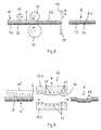
- FIGS. 3 to 7b are several embodiments of semi-finished products according to the invention, shown schematically in cross-sectional view and in plan view.
- the semifinished product W according to Fig. 3 is constructed of a sheet-like carrier material T1 made of sheet metal, thermoplastic or fiber-reinforced thermoplastic material and a homogeneous, sheet-like support material S made of thermoplastic material.
- the support material S facing side of the substrate T1 is completely covered by the support material S.
- the thickness of the support material S is designed in accordance with the application and is, for example, a multiple of the thickness of the support material T1.
- the sheet-like support material S is at least three times thicker than the sheet-like support material T1. It can also be thinner.
- This in Fig. 4 represented semifinished product W is made of a two-layer substrate T1, T2 of sheet metal (T1) and thermoplastic organic sheet (T2) and a homogeneous, flat support material S constructed of thermoplastic material.
- the organic sheet T2 is arranged between the metal sheet T1 and the single-layer thermoplastic support material S.
- the three material layers T1, T2 and S of the semifinished product W are congruent to one another.
- the thickness of the organic sheet T2 is at least equal to the thickness of the metal sheet T1; Preferably, however, the organic sheet T2 is dimensioned significantly thicker than the metal sheet T1. For example, the thickness of the organic sheet T2 is at least 1.5 times the thickness of the metal sheet T1.
- the organic sheet T2 gives one of the semifinished product (composite material) W according to Fig. 4 produced structural component B a high impact energy absorption capacity.
- the substantially homogeneously formed organic sheet T2 contains organic and / or inorganic long fibers, short fibers and / or continuous fibers as reinforcing fibers.
- the thickness of the thermoplastic support material S can again be a multiple of the thickness of the support material T1, T2.
- the sheet-like support material S is at least twice as thick as the flat, two-layer substrate T1, T2.
- This in Fig. 5 schematically represented semifinished product W 'is also formed in three layers. It is composed of a metal sheet T3, a flat, fiber-reinforced thermoplastic T4 and a homogeneous, sheet-like support material S made of thermoplastic material.
- the fiber-reinforced thermoplastic T4 contains long fibers, short fibers and / or continuous fibers as reinforcing fibers. Unlike the ones in the FIGS. 3 and 4 In the embodiments shown, the fiber-reinforced thermoplastic T4 does not completely cover the metal sheet T3 but covers a defined portion of the metal sheet T3. The subregion may have an asymmetrical shape with relatively broad and relatively narrow surface sections.
- the thermoplastic support material S arranged on the fiber-reinforced thermoplastic T4 likewise covers a defined portion of the fiber-reinforced thermoplastic T4.
- the semifinished product W 'according to Fig. 5 such that the fiber-reinforced thermoplastic T4 one or has a plurality of cutouts (recesses) which are filled with thermoplastic support material S or are.
- the present invention also includes embodiments in which the thermoplastic support material S is applied without intermediate layer T4 on a metal sheet T3, wherein in the support material S one or more cutouts (recesses) are provided, which are filled with one or several fiber reinforced thermoplastics T4 or . are.
- Fig. 5 sketched an embodiment of the method according to the invention, in which the semifinished product W 'is adjusted by trimming the support material or metal sheet T3 to the contour of the structural component to be produced later, and in which also applied to the metal sheet T3 patch (patch) T4 of a fiber-reinforced thermoplastic and the surface patch applied thereon (patch) made of thermoplastic support material S are adapted to the cutting contour K of the metal sheet T3 or to the end contour of the structural component to be produced.
- the contour of the fiber-reinforced thermoplastic T4 runs, for example, at a distance from the contour (cutting edge) K of the metal sheet T3.
- the omitted as a waste region of the metal sheet is denoted by V.
- the fiber reinforced thermoplastic T4 limited after trimming the metal sheet T3 an uncovered edge strip R, which in Fig. 5 for example, is formed circumferentially.
- thermoplastic support material S covered in the in Fig. 5 illustrated embodiment only a relatively small area of the fiber-reinforced thermoplastic T4 or metal sheet T3.
- the surface piece SP of thermoplastic support material S can also be formed, if necessary, so that its contour runs essentially parallel to the contour K 'of the fiber-reinforced thermoplastic T4 and / or parallel to the cut edge K of the metal sheet T3.
- semifinished product W is composed of a two-layer substrate made of sheet metal T1 and thermoplastic organic sheet T2 and a homogeneous, sheet-like support material S made of thermoplastic material, wherein the support material S is applied in the form of a continuous strip on the sheet carrier T1, T2, which has a partial surface area of the Covered carrier material.
- the support material S limits two uncovered edge strips R1, R2 of the organic sheet T2 or of the two-layer support material T1, T2.
- semifinished product W is also constructed of sheet metal T1, thermoplastic organic sheet T2 and a homogeneous, sheet-like support material S made of thermoplastic material.
- the fiber-reinforced thermoplastic (organo-sheet) T2 is applied in the form of a continuous strip on the metal sheet T1.
- the organic sheet T2 limits two uncovered edge strips R3, R4 of the metal sheet T1
- the strip-shaped support material S limits two uncovered continuous edge strips R1, R2 of the organic sheet T2.
- the semi-finished products W, W 'produced according to the invention are further processed in a thermal forming process into three-dimensionally shaped structural components B.
- a rib structure RS is impressed into the thermoplastic support material S at the same time.
- the semifinished product W, W ' is heated prior to feeding into the forming tool, so that the thermoplastic support material S (and optionally the fiber-reinforced thermoplastic T2 or T3) plastically reshape and can produce the rib structure RS (or leave).
- Fig. 8 is a plant for thermoforming of band-shaped semifinished product W and simultaneously impressing a rib structure RS outlined.
- the band-shaped semi-finished product W can, for example, in a continuous strip running process according to Fig. 1 prepared and wound into a coil C.
- the ribbon-shaped (possibly unwound from the coil C) semifinished product W is heated by means of a heater 11, for example a continuous furnace to a sufficient temperature for the subsequent transformation of the thermoplastic material S. Then, the heated semi-finished product W is introduced into the forming tool.
- a heater 11 for example a continuous furnace
- Only schematically outlined forming device is designed as a continuously operating forming device, by means of which the semifinished product W is formed by roll forming, for example in an L, Z or U-profile, at the same time by means of at least one structured embossing roller (structural roller) 12 a rib structure RS in the heat thermoplastic support material is molded.
- the profile produced in this way is cooled in the forming device.
- one of the forming rollers 13 and / or embossing rollers (structural rollers) 12 with one or more tempering channels (not shown) may be provided.
- the profile can be acted upon in the transport direction behind the forming or embossing rollers 13, 12, for example with a cooling medium, preferably a gaseous cooling medium.
- a cooling medium preferably a gaseous cooling medium.
- the profile in the in Fig. 8 sketched plant also still cropped, perforated, placed on final contour and / or cut to length.
- the necessary cutting and / or punching tools are in Fig. 8 exemplified only as a cutting blade 14.
- Fig. 9 is a plant for thermoforming inventively produced semifinished products W ', which are prefabricated in the form of boards D.
- the boards D can, for example, in a continuous strip running process according to Fig. 1 or a discontinuous patching and laminating process according to Fig. 2 have been produced.
- the blanks D are first heated to a sufficient temperature for the subsequent deformation of the thermoplastic material. This will for example, by means of a continuous furnace or a heat radiation device 11 'carried out. Then, the heated board D is inserted into a forming press 15.
- the shaping surfaces of the forming tools 15.1, 15.2 are formed according to the contour of the structural component B to be produced.
- the forming tool 15.1 assigned to the thermoplastic support material S has the negative 16 of a rib structure RS to be formed into the support material S.
- the heated, produced in the forming press structural component B is tempered in the press 15, for example, cooled.
- at least one of the forming tools 15.1, 15.2, preferably at least the forming tool 15.1 associated with the thermoplastic support material S has tempering channels 17.
- a conventional "cold" forming tool can be used.
- the rib structure RS formed in the thermoplastic support material S increases the rigidity and strength of the structural component B produced according to the invention.
- the rib structure RS is preferably at least partially shaped in the form of a honeycomb (FIG. Fig. 10 ), box-shaped ( Fig. 11 ) and / or auxetic rib structure ( Fig. 12 ) formed in the thermoplastic support material S.
- the box-shaped rib structure preferably has differently sized, in particular substantially rectangular boxes (cf. Fig. 11 ).
- FIGS. 13 and 14 schematically show two structural components produced according to the invention.
- This in Fig. 13 illustrated structural component B ' has a single-layer shell made of sheet metal or a fiber-reinforced thermoplastic as support material T and a rib structure RS of thermoplastic support material S.
- structural component B shown has a two-layer shell made of sheet metal T1 and a fiber-reinforced thermoplastic material T2 as support material T and likewise a rib structure RS made of thermoplastic support material S.
- vehicle parts for example side impact beams, bumpers, sills, reinforcing plates, roof pillars and also vehicle skin parts, e.g. an outside door skin with inside reinforcing structure and a hood with integrated internal structure.
Landscapes
- Engineering & Computer Science (AREA)
- Mechanical Engineering (AREA)
- Physics & Mathematics (AREA)
- Fluid Mechanics (AREA)
- Laminated Bodies (AREA)
- Casting Or Compression Moulding Of Plastics Or The Like (AREA)
- Superstructure Of Vehicle (AREA)
- Body Structure For Vehicles (AREA)
- Moulding By Coating Moulds (AREA)
Description
Die Erfindung betrifft ein Verfahren zum Herstellen eines Strukturbauteils, insbesondere eines Strukturbauteils für eine Karosserie, bei dem ein flächiges Trägermaterial aus Metall, thermoplastischem Kunststoff und/oder faserverstärktem thermoplastischem Kunststoff zu einem dreidimensionalen Bauteil umgeformt wird, und bei dem das Trägermaterial mit Stützmaterial aus thermoplastischem Kunststoff versehen wird, so dass das Trägermaterial und das Stützmaterial einen stoffschlüssigen Materialverbund bilden.The invention relates to a method for producing a structural component, in particular a structural component for a body, in which a planar carrier material made of metal, thermoplastic material and / or fiber-reinforced thermoplastic material is formed into a three-dimensional component, and in which the carrier material with support material made of thermoplastic material is provided so that the carrier material and the support material form a cohesive composite material.
Der Begriff Strukturbauteil umfasst im vorliegenden Kontext insbesondere Leichtbauteile und Stützbauteile für Fahrzeuge.The term structural component comprises in the present context in particular lightweight components and support components for vehicles.
Aus der
Die
Als weiteren Stand der Technik wird die
Diese bekannten Verfahren zur Herstellung von Leichtbauteilen in Hybridform erfordern relativ viele Fertigungsschritte bzw. die Kombination mehrerer Prozesse.These known methods for producing lightweight components in hybrid form require relatively many manufacturing steps or the combination of multiple processes.
Davon ausgehend lag der vorliegenden Erfindung die Aufgabe zugrunde, ein Verfahren der eingangs genannten Art anzugeben, das relativ wenige Fertigungsschritte erfordert und eine relativ hohe Produktivität bietet, insbesonde um eine ausreichende Steifigkeit und Festigkeit des Strukturbauteils sicherzustellen.On this basis, the present invention has the object to provide a method of the type mentioned above, which requires relatively few manufacturing steps and provides a relatively high productivity, insbesonde particular to ensure sufficient rigidity and strength of the structural component.
Zur Lösung dieser Aufgabe wird ein Verfahren mit den Merkmalen des Anspruchs 1 vorgeschlagen.To solve this problem, a method with the features of claim 1 is proposed.
Das erfindungsgemäße Verfahren ist dadurch gekennzeichnet, dass das Trägermaterial einschichtig oder als mehrschichtiger Materialverbund ausgebildet ist, wobei eine der Lagen des mehrschichtigen Materialverbundes Metall besteht der Materialverbund aus Trägermaterial und Stützmaterial vor dem Umformen des Trägermaterials zu dem dreidimensionalen Bauteil hergestellt wird, wobei die Schichtdicke des Stützmaterials mindestens das zweifache der Dicke des flächigen, ein- oder mehrlagigen Trägermaterials beträgt, dass der Materialverbund vor dem Umformen erhitzt wird, um eine Umformung des thermoplastischen Kunststoffs zu ermöglichen, dass während des Umformens des Materialverbundes eine Rippenstruktur in das Stützmaterial eingeprägt wird, und dass das dreidimensionale, die Rippenstruktur aufweisende Bauteil temperiert wird.The inventive method is characterized in that the carrier material is formed as a single layer or as a multi-layer composite material, wherein one of the layers of the multilayer material composite metal is the material composite of carrier material and support material is formed prior to forming the carrier material to the three-dimensional component, wherein the layer thickness of the support material is at least twice the thickness of the flat, single or multilayer carrier material, that the composite material is heated prior to forming to allow a transformation of the thermoplastic material, that during the forming of the composite material, a rib structure is embossed into the support material, and that three-dimensional, the rib structure having component is tempered.
Das erfindungsgemäße Verfahren basiert auf der Idee, ein fertig konsolidiertes Halbzeug zu schaffen, das in einem thermischen Umformprozess zu einem fertigen Strukturbauteil mit der gewünschten Endgeometrie weiterverarbeitet wird. Der thermische Umformprozess kann dabei gängige Operationsstufen wie Lochen, Schneiden und/oder Abstellen beinhalten. Dementsprechend sieht eine bevorzugte Ausgestaltung des erfindungsgemäßen Verfahrens vor, dass das die Rippenstruktur aufweisende Bauteil beschnitten, gelocht und/oder auf Endkontur abgestellt wird.The inventive method is based on the idea to create a finished consolidated semi-finished, which is further processed in a thermal forming process to a finished structural component with the desired final geometry. The thermal forming process can involve common operating stages such as punching, cutting and / or stopping. Accordingly, a preferred embodiment of the method according to the invention provides that the component having the rib structure is trimmed, perforated and / or placed on the final contour.
Dadurch, dass das Einformen der Rippenstruktur in das Stützmaterial zeitlich parallel zu dem Umformen des flächigen Trägermaterials durchgeführt wird, ist die Anzahl der Fertigungsschritte bei dem erfindungsgemäßen Verfahren erheblich verringert. Insbesondere wird dadurch eine erhöhte Produktivität ermöglicht bzw. erzielt.Due to the fact that the molding of the rib structure into the support material is carried out in parallel to the forming of the sheet-like support material, the number of production steps in the method according to the invention is considerably reduced. In particular, this enables or achieves increased productivity.
Damit das erfindungsgemäß hergestellte Strukturbauteil ein hohes Energieaufnahmevermögen (Stoßenergieabsorptionsvermögen) aufweist, wird für dessen Trägermaterial vorzugsweise faserverstärkter thermoplastischer Kunststoff (Organoblech) verwendet, wobei das Trägermaterial einschichtig aber auch mehrschichtiger insbesondere als sandwichartiger Materialverbung ausgebildet sein kann, und wobei eine der Lagen (Schichten) des mehrschichtigen Materialverbundes aus Metall, besonders bevorzugt aus Stahl, beispielsweise verzinktem Stahlblech bc-steht.In order for the structural component produced according to the invention to have a high energy absorption capacity (impact energy absorption capacity), preferably fiber-reinforced thermoplastic material (organic sheet) is used for the carrier material, wherein the carrier material may be single-layered but also multi-layered, in particular as a sandwiched material compound, and one of the layers of the multilayer composite material of metal, particularly preferably of steel, for example galvanized steel sheet bc stands.
Als flächiges Trägermaterial wird bei dem erfindungsgemäßen Verfahren Metallblech, thermoplastisches Tafel- oder Flachmaterial und/oder faserverstärktes, thermoplastisches Tafel- oder Flachmaterial (sogenanntes Organoblech) verwendet. Das Trägermaterial kann dabei ein- oder mehrlagig, insbesondere zweilagig oder als Sandwichmaterial ausgebildet sein. Die Lagen des mehrlagigen Trägermaterials bestehen vorzugsweise aus unterschiedlichen Materialien, beispielsweise aus Metall und thermoplastischem Kunststoff mit oder ohne Faserverstärkung. Des Weiteren umfasst das erfindungsgemäße Verfahren Ausführungsformen, bei denen das flächige Trägermaterial als Bandmaterial oder als Zuschnitt, zum Beispiel in Form einer Platine verarbeitet wird.As a sheet-like support material in the inventive method sheet metal, thermoplastic sheet or flat material and / or fiber-reinforced thermoplastic sheet or flat material (so-called organo sheet) is used. The carrier material may be one or more layers, in particular two-ply or formed as a sandwich material. The layers of the multilayer carrier material are preferably made of different materials, for example of metal and thermoplastic material with or without fiber reinforcement. Furthermore, the method according to the invention comprises embodiments in which the planar carrier material is processed as a strip material or as a blank, for example in the form of a circuit board.
Das Trägermaterial hat insbesondere die Funktion, die Geometrie (Form) des fertigenden Strukturbauteils zu definieren. So kann beispielsweise Metallblech als Trägermaterial die Außenhaut des erfindungsgemäß hergestellten Strukturbauteils definieren. Des Weiteren verleiht das ein- oder mehrlagige Trägermaterial dem erfindungsgemäß hergestellten Strukturbauteil ein bestimmtes Maß an Steifigkeit und Festigkeit, welches jedoch allein genommen für den vorgesehenen Einsatzzweck des Strukturbauteil in der Regel nicht ausreichend ist. Zur Sicherstellung einer ausreichenden Steifigkeit und Festigkeit des Strukturbauteils dient in Ergänzung zu dem umgeformten Trägermaterial das Stützmaterial mit der darin eingeformten Rippenstruktur.In particular, the carrier material has the function of defining the geometry (shape) of the finished structural component. For example, metal sheet as a carrier material can define the outer skin of the structural component produced according to the invention. Furthermore, the single-layer or multi-layered carrier material imparts a certain degree of rigidity and strength to the structural component produced according to the invention, which alone, however, is generally insufficient for the intended intended use of the structural component. To ensure sufficient rigidity and strength of the structural component is used in addition to the transformed support material, the support material with the molded therein rib structure.
Sofern in dem erfindungsgemäßen Verfahren faserverstärkter thermoplastischer Kunststoff als Trägermaterial bzw. neben Metall als zusätzliches Trägermaterial verwendet wird, so enthält das Trägermaterial Lang-, Kurz- und/oder Endlosfasern aus anorganischem und/oder organischem Material. Unter Kurzfasern werden dabei Fasern mit einer Länge im Bereich von 0,1 bis 1 mm, unter Langfasern Fasern mit einer Länge im Bereich von 1 mm bis 50 mm, und unter Endlosfasern Fasern mit einer Faserlänge größer 50 mm verstanden.If in the method according to the invention fiber-reinforced thermoplastic material is used as the carrier material or in addition to metal as an additional carrier material, the carrier material contains long, short and / or continuous fibers of inorganic and / or organic material. Short fibers mean fibers with a length in the range of 0.1 to 1 mm, long fibers fibers with a length in the range of 1 mm to 50 mm, and continuous fibers with a fiber length of more than 50 mm.
Bei den anorganischen Fasern (Verstärkungsfasern) handelt es sich vorzugsweise um Glas-, Keramik- und/oder Basaltfasern. Die organischen Fasern (Verstärkungsfasern) bestehen dagegen beispielsweise aus Aramid-, Nylon- und/oder Kohlenstofffasern.The inorganic fibers (reinforcing fibers) are preferably glass, ceramic and / or basalt fibers. By contrast, the organic fibers (reinforcing fibers) consist, for example, of aramid, nylon and / or carbon fibers.
Bei dem thermoplastischen Kunststoff des Trägermaterials bzw. des Stützmaterials handelt es sich vorzugsweise um Polyamid (PA), Polypropylen (PP), Polycarbonat (PC), (PC), Polyethersulfon (PES), Acrylnitril-Butadien-Styrol (ABS), Styrol-Acrylnitril-Copolymerisat (SAN), Polyoxymethylen (POM), Polytetrafluorethylen (PTFE), thermoplastisches Polyurethan (TPU), Polyethylen (PE), Polybutylenterephthalat (PBT) und/oder deren Mischungen. Vorzugsweise weist der in dem erfindungsgemäßen Verfahren verwendete thermoplastische Kunststoff eine Temperaturbeständigkeit von mindestens 80°C, besonders bevorzugt mindestens 100°C auf.The thermoplastic material of the carrier material or of the support material is preferably polyamide (PA), polypropylene (PP), polycarbonate (PC), (PC), polyethersulfone (PES), acrylonitrile-butadiene-styrene (ABS), styrene-acrylonitrile copolymer (SAN), polyoxymethylene (POM), polytetrafluoroethylene (PTFE), thermoplastic polyurethane (TPU), polyethylene (PE), polybutylene terephthalate ( PBT) and / or mixtures thereof. Preferably, the thermoplastic used in the process according to the invention has a temperature resistance of at least 80 ° C, more preferably at least 100 ° C.
Das thermoplastische Stützmaterial wird mit einer Schichtdicke auf das flächige, ein- oder mehrlagige Trägermaterial aufgebracht, die je nach Anwendungsfall entsprechend der zu erzeugenden Rippendicke und/oder Rippenggröße ausgelegt wird, vorzugsweise mindestens das Zweifache, besonders bevorzugt mindestens das Dreifache der Dicke des flächigen, ein- oder mehrlagigen Trägermaterials beträgt.The thermoplastic support material is applied with a layer thickness on the flat, single or multilayer carrier material, which is designed according to the application according to the rib thickness and / or Rippenggröße to be produced, preferably at least twice, more preferably at least three times the thickness of the sheet - or multilayer carrier material.
Das Stützmaterial kann in mehreren Lagen auf das Trägermaterial aufgebracht werden. Eine weitere Ausgestaltung des erfindungsgemäßen Verfahrens ist dadurch gekennzeichnet, dass die Lagen des Stützmaterials mit unterschiedlicher Materialzusammensetzung, unterschiedlicher Flächengröße und/oder unterschiedlicher Schichtdicke auf das Trägermaterial aufgebracht werden. Auf diese Weise lassen sich aus dem erfindungsgemäß hergestellten Materialverbund (Halbzeug) Strukturteile mit optimiertem Stoßenergieaufnahmevermögen bzw. optimierter Steifigkeit bei relativ geringem Bauteilgewicht erzeugen.The support material can be applied to the carrier material in several layers. A further embodiment of the method according to the invention is characterized in that the layers of the support material with different material composition, different area size and / or different layer thickness are applied to the carrier material. In this way, it is possible to produce structural parts with optimized impact energy absorption capacity or optimized rigidity with a relatively low component weight from the material composite (semi-finished product) produced according to the invention.
Eine weitere vorteilhafte Ausgestaltung des erfindungsgemäßen Verfahrens ist dadurch gekennzeichnet, dass das Stützmaterial auf definierte Teilflächenbereiche des Trägermaterials aufgebracht wird. Auch diese Ausgestaltung ist für eine Optimierung der Steifigkeit und/oder des Stoßenergieaufnahmevermögens des Strukturbauteils bei relativ geringem oder minimiertem Bauteilgewicht von Vorteil. Hierzu sieht eine weitere Ausgestaltung des Verfahrens vor, dass auf verschiedene Teilflächenbereiche des Trägermaterials das Stützmaterial mit unterschiedlicher Materialzusammensetzung und/oder unterschiedlicher Schichtdicke aufgebracht wird.A further advantageous embodiment of the method according to the invention is characterized in that the support material is applied to defined partial surface areas of the carrier material. This refinement is also advantageous for optimizing the rigidity and / or the impact energy absorption capacity of the structural component with a relatively low or minimized component weight. For this purpose, a further embodiment of the method provides that on different partial surface areas of the carrier material, the support material with different Material composition and / or different layer thickness is applied.
Zur Optimierung der Steifigkeit und/oder des Stoßenergieaufnahmevermögens des Strukturbauteils kann gemäß einer weiteren vorteilhaften Ausgestaltung des erfindungsgemäßen Verfahrens das Stützmaterial in Form eines einzelnen Streifens oder in Form mehrerer Streifen auf das Trägermaterial aufgebracht werden, und zwar so, dass der jeweilige Streifen einen bestimmten Teilflächenbereich des Trägermaterials bedeckt.To optimize the rigidity and / or the impact energy absorption capacity of the structural component, the support material can be applied in the form of a single strip or in the form of a plurality of strips on the carrier material, in such a way that the respective strip has a certain partial surface area of the Covered carrier material.
Eine weitere vorteilhafte Ausgestaltung des erfindungsgemäßen Verfahrens besteht darin, dass das Umformen des aus dem flächigen Trägermaterial und dem Stützmaterial aufgebauten Materialverbundes und das Temperieren des Bauteils mittels eines temperierten Umformwerkzeuges durchgeführt werden. Bei dem Umformwerkzeug kann es sich um ein "kaltes", konventionelles Werkzeug handeln, es kann aber auch temperierbar, d.h. aktiv kühlbar und/oder erwärmbar sein, je nach Bedarf. Hierdurch kann die Produktivität des Verfahrens weiter gesteigert werden.A further advantageous embodiment of the method according to the invention consists in that the forming of the composite material composed of the flat carrier material and the supporting material and the tempering of the component are carried out by means of a tempered forming tool. The forming tool can be a "cold" conventional tool, but it can also be tempered, i. be actively coolable and / or heatable, as needed. As a result, the productivity of the process can be further increased.
Eine besonders hohe Produktivität lässt sich insbesondere dann erzielen, wenn gemäß einer weiteren Ausgestaltung des erfindungsgemäßen Verfahrens der aus dem Trägermaterial und dem Stützmaterial aufgebaute Materialverbund in einem kontinuierlichen Bandlaufprozess hergestellt wird, wobei bandförmiges Trägermaterial und bandförmiges Stützmaterial miteinander stoffschlüssig verbunden werden. Diese Ausgestaltung eignet sich insbesondere für die Herstellung von länglichen, profilförmigen Strukturbauteilen, zum Beispiel von Seitenaufprallträgern, Front- sowie Heckstoßfängern, Schwellern und/oder Fahrzeugdachsäulen.A particularly high productivity can be achieved in particular if, according to a further embodiment of the method according to the invention, the material composite constructed from the carrier material and the support material is produced in a continuous strip running process, wherein band-shaped carrier material and band-shaped support material are connected to one another in a material-locking manner. This embodiment is particularly suitable for the production of elongated, profile-shaped structural components, for example of side impact beams, front and rear bumpers, sills and / or vehicle roof pillars.
Der im kontinuierlichen Bandlaufprozess hergestellte Materialverbund kann zu einem Coil aufgewickelt oder zu Platinen abgelängt werden, wobei das jeweilige Coil bzw. die Platinen anschließend zu dem gewünschten Strukturbauteil weiterverarbeitet werden können.The composite material produced in the continuous strip running process can be wound into a coil or cut to form blanks, wherein the respective coil or blanks can then be further processed to the desired structural component.
Eine andere Ausgestaltung des erfindungsgemäßen Verfahrens sieht vor, dass der aus dem Trägermaterial und dem Stützmaterial aufgebaute Materialverbund in einem diskontinuierlichen Laminier- und/oder Materialauftragsprozess hergestellt wird, wobei auf vorkonfektionierte Trägermaterialplatinen zumindest partiell Stützmaterial in der Weise aufgebracht wird, dass eine stoffschlüssige Verbindung zwischen der jeweiligen Trägermaterialplatine und dem darauf aufgebrachten Stützmaterial erzeugt wird. Diese Ausgestaltung ist insbesondere dann vorteilhaft, wenn das Stützmaterial auf einen oder mehrere definierte Teilflächenbereiche des Trägermaterials aufgebracht werden soll. Auf diese Weise können maßgeschneiderte Stützmaterial-Flächenabschnitte (Zuschnitte) auf einen oder mehrere definierte Teilflächenbereiche des Trägermaterials aufgebracht werden. Die maßgeschneiderten Stützmaterial-Flächenabschnitte können sich dabei in ihrer Form (Geometrie), Schichtdicke und/oder Materialbeschaffenheit unterscheiden.Another embodiment of the method according to the invention provides that the material composite constructed from the carrier material and the support material is produced in a discontinuous lamination and / or material application process, wherein support material is at least partially applied to prefabricated carrier material plates in such a way that a cohesive connection between the respective carrier board and the support material applied thereto. This embodiment is particularly advantageous when the support material is to be applied to one or more defined partial surface areas of the carrier material. In this way, tailor-made support material surface sections (blanks) can be applied to one or more defined partial surface regions of the carrier material. The tailor-made support material surface sections may differ in their shape (geometry), layer thickness and / or material properties.
Der Aufbau des aus dem flächigen Trägermaterial und dem thermoplastischen Stützmaterial hergestellten Materialverbundes (Halbzeuges) kann bei dem erfindungsgemäßen Verfahren in unterschiedlicher Weise ausgeführt sein bzw. werden. In einer Ausgestaltung des Verfahrens ist vorgesehen, dass das Stützmaterial in Form einer homogenen, flächigen Schicht auf das Trägermaterial aufgebracht wird. Diese Ausgestaltung lässt sich prozesstechnisch relativ einfach mittels eines kontinuierlichen Bandlaufprozess, aber bei Verwendung von vorkonfektionierten Platinen bzw. Tafeln in einem Patch- und Laminierprozess verwirklichen. Unter "Patchen" bzw. Patchprozess wird hier das Aufbringen von zugeschnittenen bzw. maßgeschneiderten Stützmaterial-Flächenstücken verstanden.The construction of the composite material (semifinished product) produced from the flat carrier material and the thermoplastic support material can be or are carried out in different ways in the method according to the invention. In one embodiment of the method, it is provided that the support material is applied to the carrier material in the form of a homogeneous, flat layer. This refinement can be implemented relatively simply in terms of process technology by means of a continuous strip running process, but when prefabricated blanks or panels are used in a patching and laminating process. The term "patching" or "patching process" here refers to the application of tailored or customized support material surface pieces.
Nach einer weiteren Ausgestaltung des Verfahrens ist vorgesehen, dass als Stützmaterial faserverstärkter thermoplastischer Kunststoff verwendet wird. Aus dem so erhaltenen Materialverbund (konsolidiertes Halbzeug) lässt sich durch thermisches Umformen ein Strukturbauteil, insbesondere Karosserieteil, mit relativ geringem Gewicht und hoher Steifigkeit sowie Festigkeit erzeugen. Durch die Verwendung von faserverstärktem thermoplastischem Kunststoff als Stütz-material lassen sich Strukturbauteile, insbesondere Leichtbauteile, mit hohem Stoßenergieaufnahmevermögen erzielen.According to a further embodiment of the method, it is provided that fiber-reinforced thermoplastic material is used as the support material. From the composite material thus obtained (consolidated semifinished product), a structural component, in particular a body part, with relatively low weight and high rigidity and strength can be produced by thermal forming. By the use of fiber-reinforced thermoplastic material as a support material can be structural components, in particular lightweight components, achieve high impact energy absorption capacity.
Die die Steifigkeit sowie Festigkeit erhöhende Rippenstruktur des erfindungsgemäß hergestellten Strukturbauteils wird anforderungsgerecht ausgelegt, beispielsweise als waben-, rechteck- oder rautenförmige Struktur ausgebildet. Die Struktur/Form wird anwendungsabhängig ausgelegt, so dass bzw. wobei auch unregelmäßige Strukturen gewählt werden können. Eine entsprechend ausgebildete Rippenstruktur verleiht dem Strukturbauteil bei geringem Bauteilgewicht eine hohe Steifigkeit sowie Festigkeit.The stiffness and strength increasing rib structure of the structural component according to the invention is designed according to requirements, for example, formed as a honeycomb, rectangular or diamond-shaped structure. The structure / shape is designed application-dependent, so that or even irregular structures can be selected. A correspondingly designed rib structure gives the structural component high rigidity and strength with low component weight.
Eine weitere vorteilhafte Ausgestaltung des erfindungsgemäßen Verfahrens ist dadurch gekennzeichnet, dass die Rippenstruktur zumindest partiell in Form einer auxetischen Rippenstruktur eingeprägt wird. Eine auxetische Struktur besitzt Querverformungseigenschaften, die sich gegensätzlich zu denen konventioneller Materialien, insbesondere einer klassischen Wabenstruktur verhalten. Denn während bei konventionellen Materialien bzw. Rippenstrukturen eine positive Zugbeanspruchung zu einer Verlängerung in Zugrichtung und gleichzeitig zu Verkürzungen in den dazu senkrechten Richtungen führt, erzeugen unidirektionale Zugspannungen bei einer auxetischen Struktur positive Längenänderungen in allen drei Raumrichtungen. Durch das Einformen einer auxetischen Rippenstruktur lassen sich insbesondere Eigenschaften wie Steifigkeit, Stoßenergieabsorptionsvermögen, Nachgiebigkeit und Bruchfestigkeit sehr vorteilhaft beeinflussen. Eine auxetische Rippenstruktur ermöglicht insbesondere eine signifikante Erhöhung der thermischen Beulstabilität.A further advantageous embodiment of the method according to the invention is characterized in that the rib structure is impressed at least partially in the form of an auxetic rib structure. An auxetic structure has transverse deformation properties that are contrary to those of conventional materials, especially a classic honeycomb structure. While in conventional materials or rib structures a positive tensile stress leads to an extension in the tensile direction and at the same time to shortenings in the perpendicular directions, unidirectional tensile stresses in an auxetic structure produce positive changes in length in all three spatial directions. In particular, properties such as stiffness, impact energy absorption capacity, resilience and breaking strength can be influenced very advantageously by molding in an auxetic rib structure. In particular, an auxetic rib structure enables a significant increase in thermal buckling stability.
Weitere bevorzugte und vorteilhafte Ausgestaltungen des erfindungsgemäßen Verfahrens lassen sich den Unteransprüchen entnehmen.Further preferred and advantageous embodiments of the method according to the invention can be taken from the subclaims.
Nachfolgend wird die Erfindung anhand einer mehrere Ausführungsbeispiele darstellenden Zeichnung näher erläutert. Darin zeigen schematisch:
- Fig. 1
- eine Anlage zur Herstellung eines Halbzeuges, das aus flächigem Trägermaterial und thermoplastischem Stützmaterial aufgebaut ist;
- Fig. 2
- eine weitere Anlage zur Herstellung eines Halbzeuges, das aus flächigem Trägermaterial und thermoplastischem Stützmaterial aufgebaut ist;
- Fig. 3 und 4
- erfindungsgemäß hergestellte Halbzeuge, jeweils in Querschnittansicht;
- Fig. 5
- ein weiteres erfindungsgemäß hergestelltes Halbzeug, in Draufsicht;
- Fig. 6a und 6b
- ein weiteres erfindungsgemäß hergestelltes Halbzeug, in Querschnittansicht und in Draufsicht;
- Fig. 7a und 7b
- noch ein weiteres erfindungsgemäß hergestelltes Halbzeug, in Querschnittansicht und in Draufsicht;
- Fig. 8
- eine Anlage zum thermischen Umformen eines erfindungsgemäß hergestellten Halbzeuges,
- Fig. 9
- eine weitere Anlage zum thermischen Umformen eines erfindungsgemäß hergestellten Halbzeuges,
- Fig. 10
bis 12 - verschiedene Rippenstrukturen von erfindungsgemäß hergestellten Strukturbauteilen, jeweils in Draufsicht; und
- Fig. 13
und 14 - zwei erfindungsgemäß hergestellte Strukturbauteile, jeweils in perspektivischer Darstellung.
- Fig. 1
- a plant for the production of a semi-finished product, which is composed of sheet-like support material and thermoplastic support material;
- Fig. 2
- a further plant for the production of a semi-finished product, which is composed of sheet-like support material and thermoplastic support material;
- 3 and 4
- Semi-finished products produced according to the invention, each in cross-sectional view;
- Fig. 5
- a further produced according to the invention semifinished product, in plan view;
- Fig. 6a and 6b
- a further produced according to the invention semi-finished product, in cross-sectional view and in plan view;
- Fig. 7a and 7b
- still another inventively produced semi-finished product, in cross-sectional view and in plan view;
- Fig. 8
- a plant for thermoforming a semifinished product produced according to the invention,
- Fig. 9
- a further system for the thermoforming of a semifinished product produced according to the invention,
- 10 to 12
- various rib structures of structural components according to the invention, each in plan view; and
- FIGS. 13 and 14
- two structural components produced according to the invention, each in perspective view.
In
Des Weiteren wird auf das ein- oder mehrschichtige Trägermaterialband T1, T2, bei dem es sich vorzugsweise um ein Metallband oder ein Metall-Kunststoff-Verbundband handelt, ein thermoplastisches Stützmaterial S aufgebracht. Das thermoplastische Stützmaterial S liegt in dem dargestellten Ausführungsbeispiel ebenfalls als aufgewickeltes Band (Coil) vor. Mit 2 ist wiederum eine Heizvorrichtung bezeichnet, mittels der die mit dem Trägermaterialband T1, T2 stoffschlüssig zu verbindende Seite des Stützmaterialbandes S plastifiziert oder angeliert wird.Furthermore, a thermoplastic support material S is applied to the single-layer or multi-layered substrate strip T1, T2, which is preferably a metal strip or a metal-plastic composite strip. The thermoplastic support material S is also present in the illustrated embodiment as a wound band (coil). 2 again denotes a heating device by means of which the side of the support material band S to be materially bonded to the substrate tape T1, T2 is plasticized or gelled.
Die Bänder T1, T2, S werden mittels Umlenk- bzw. Führungsrollen zusammengeführt, in die Bandpresse P geleitet und dort miteinander zu einem bandförmigen Materialverbund W verpresst. Die Bandpresse P weist hierzu beheizte Rollen 3 und eine diesen Rollen 3 in Transportrichtung nachfolgende Kühleinrichtung auf. Die Kühleinrichtung umfasst beispielsweise gekühlte Andruckrollen 4, die in der Bandpresse angeordnet sind. Die Dicke des thermoplastischen Stützmaterialsbandes S bzw. des auf das Trägermaterial T1, T2 aufgetragenen Stützmaterials S ist anwendungsgerecht ausgelegt und beträgt beispielsweise ein Vielfaches der Dicke des ein- oder mehrlagigen Trägermaterialbandes T1, T2. Beispielsweise liegt die Dicke des Trägermaterialbandes T1 und/oder T2 im Bereich von 0,5 bis 1,5 mm, während die Dicke des Bandes S aus thermoplastischem Stützmaterial im Bereich von 4 bis 8 mm liegt.The bands T1, T2, S are brought together by means of deflection or guide rollers, passed into the belt press P and there pressed together to form a band-shaped composite material W. For this purpose, the belt press P has heated
Der in dem kontinuierlichen Bandlaufprozess erzeugte bandförmige Materialverbund W wird zu einem Coil C aufgewickelt oder mittels einer Schneideeinrichtung 5 in Platinen D bestimmter Länge abgelängt. Das Coil C bzw. die Platinen D stehen somit als konsolidiertes Halbzeug W, W' zur Verfügung, um anschließend zu einem dreidimensionalen, eine Rippenstruktur aufweisenden Strukturbauteil, beispielsweise einem Karosserieteil verarbeitet zu werden. Die Weiterverarbeitung des konsolidierten Halbzeuges W, W', d.h. die Herstellung des Strukturbauteils wird nachfolgend anhand von in den
Die Platinen oder Tafeln T3 werden beispielsweise durch Abwickeln und Ablängen eines entsprechenden Coils C2 erzeugt und anschließend mittels einer Transfervorrichtung 6, vorzugsweise einem Roboter, zu einer Bearbeitungsstation transportiert, in welcher auf die jeweilige Platine oder Tafel T3 thermoplastisches Stützmaterial S' aufgebracht wird. Das Stützmaterial S' kann dabei einlagig oder mehrlagig aufgebracht werden. In dem dargestellten Ausführungsbeispiel erfolgt das Auftragen des Stützmaterials S' mittels mindestens einer Extrusionsvorrichtung. Die Extrusionsvorrichtung weist hierzu vorzugsweise mindestens einen relativ zu der Platine/Tafel verfahrbaren Auftragskopf (Extruderauslass) 7 auf. Die Bearbeitungsstation kann beispielsweise ein Transportband 8 zur Aufnahme der Platine/Tafel T3 aufweisen, wobei der Auftragskopf 7 in Transportrichtung und zurück und/oder quer zur Transportrichtung verfahrbar ist. Alternativ kann der mindestens eine Auftragskopf 7 auch an einem in mehrere, quer zueinander verlaufende Richtungen bewegbaren Schlitten oder an einem Roboterarm montiert sein. Darüber hinaus kann eine entsprechende Extrusionsvorrichtung mit einem Auftragskopf 10 zum Aufbringen eines faserverstärkten Thermoplasten als zweite Trägermaterialschicht (Zwischenschicht) T4 vorgesehen sein.The boards or panels T3 are generated, for example, by unwinding and cutting to length of a corresponding coil C2 and then by means of a
Ferner liegt es im Rahmen der vorliegenden Erfindung, anstelle der in
Des Weiteren umfasst das erfindungsgemäße Verfahren auch Ausführungsformen, bei denen die aufeinander gelegten Platinen, Tafeln T3, T4 bzw. Flächenstücke S' erhitzt und durch Aneinanderpressen in einer diskontinuierlich arbeitenden Presse zu einem flächigen Materialverbund (konsolidiertes Halbzeug) W' stoffschlüssig miteinander verbunden werden.Furthermore, the inventive method also includes embodiments in which the stacked boards, sheets T3, T4 or patches S 'are heated and joined together by pressing together in a discontinuous press to form a two-dimensional composite material (consolidated semi-finished) W'.
Die so, insbesondere gemäß
In den
Das Halbzeug W gemäß
Das in
Das in
Des Weiteren liegt es im Rahmen der vorliegenden Erfindung, das Halbzeug W' gemäß
Des Weiteren ist in
Das Flächenstück aus thermoplastischem Stützmaterial S bedeckt in dem in
Das in den
Das in den
Die in den
Die erfindungsgemäß hergestellten Halbzeuge W, W' werden in einem thermischen Umformprozess zu dreidimensional geformten Strukturbauteile B weiterverarbeitet. Während des Umformprozesses wird gleichzeitig eine Rippenstruktur RS in das thermoplastische Stützmaterial S eingeprägt. Hierzu wird das Halbzeug W, W' vor dem Zuführen in das Umformwerkzeug aufgeheizt, so dass sich das thermoplastische Stützmaterial S (und gegebenenfalls der faserverstärkte Thermoplast T2 oder T3) plastisch umformen und die Rippenstruktur RS erzeugen lässt (bzw. lassen).The semi-finished products W, W 'produced according to the invention are further processed in a thermal forming process into three-dimensionally shaped structural components B. During the forming process, a rib structure RS is impressed into the thermoplastic support material S at the same time. For this purpose, the semifinished product W, W 'is heated prior to feeding into the forming tool, so that the thermoplastic support material S (and optionally the fiber-reinforced thermoplastic T2 or T3) plastically reshape and can produce the rib structure RS (or leave).
In
In
Die Platinen D werden zunächst auf eine für die nachfolgende Umformung des thermoplastischen Materials ausreichende Temperatur aufgeheizt. Dies wird beispielsweise mittels eines Durchlaufofens oder einer Heizstrahleinrichtung 11' durchgeführt. Sodann wird die aufgeheizte Platine D in eine Umformpresse 15 eingelegt. Die Formungsflächen der Umformwerkzeuge 15.1, 15.2 sind entsprechend der Kontur des herzustellenden Strukturbauteils B ausgebildet. Zudem weist das dem thermoplastischen Stützmaterial S zugeordnete Umformwerkzeug 15.1 das Negativ 16 einer in das Stützmaterial S einzuformenden Rippenstruktur RS auf. Das aufgeheizte, in der Umformpresse hergestellte Strukturbauteil B wird in der Presse 15 temperiert, beispielsweise abgekühlt. Hierzu weist zumindest eines der Umformwerkzeuge 15.1, 15.2, vorzugsweise zumindest das dem thermoplastischen Stützmaterial S zugeordnete Umformwerkzeug 15.1, Temperierkanäle 17 auf. Je nach Anwendung kann auch ein konventionelles "kaltes" Umformwerkzeug verwendet werden.The blanks D are first heated to a sufficient temperature for the subsequent deformation of the thermoplastic material. this will for example, by means of a continuous furnace or a heat radiation device 11 'carried out. Then, the heated board D is inserted into a forming
Die in das thermoplastische Stützmaterial S eingeformte Rippenstruktur RS erhöht die Steifigkeit und Festigkeit des erfindungsgemäß hergestellten Strukturbauteils B. Die Rippenstruktur RS wird vorzugsweise zumindest partiell in Form einer wabenförmigen (
Prinzipiell, in den in der Zeichnung dargestellten Ausführungsbeispielen aber nicht gezeigt, liegt es auch im Rahmen der vorliegenden Erfindung, eine sogenannte "Funktionsintegration" im hergestellten Bauteil vorzusehen, d.h. dass Einleger, wie beispielsweise Schrauben, Muttern, Inserts etc., im Werkzeug positioniert und anschließend im formgebenden Prozess vom Stützmaterial aufgenommen ("umspritzt") werden, so dass ein Kraft- und Formschluss resultiert. Neben den genannten Rippenstrukturen können auch lokal beispielsweise Anschraubdome aus dem Stützmaterial geformt werden.In principle, but not shown in the embodiments shown in the drawing, it is also within the scope of the present invention to provide a so-called "functional integration" in the manufactured component, i. that depositors, such as screws, nuts, inserts, etc., positioned in the tool and then taken in the molding process of the support material ("encapsulated"), so that a positive and positive connection results. In addition to the aforementioned rib structures, it is also possible, for example, to locally form screw-on domes from the support material.
Die
Mit dem erfindungsgemäßen Verfahren können Strukturbauteile, die einer statischen und/oder dynamischen Belastung unterliegen, hergestellt werden, insbesondere Fahrzeugteile, zum Beispiel Seitenaufprallträger, Stoßfänger, Schweller, Verstärkungsbleche, Dachsäulen und auch Fahrzeugaußenhautteile, wie z.B. eine Türaußenhaut mit innenseitiger Verstärkungsstruktur und eine Motorhaube mit integrierter Innenstruktur.With the method according to the invention, it is possible to produce structural components which are subject to static and / or dynamic stress, in particular vehicle parts, for example side impact beams, bumpers, sills, reinforcing plates, roof pillars and also vehicle skin parts, e.g. an outside door skin with inside reinforcing structure and a hood with integrated internal structure.
Claims (15)
- Method for producing a structural component (B, B') for a vehicle body, in which method a flat carrier material (T1, T2, T3, T4) made of metal, thermoplastic material and/or fiber-reinforced thermoplastic material is formed to give a three-dimensional component, and in which method the carrier material (T1, T2, T3, T4) is provided with supporting material (S, S') made of thermoplastic material, such that the carrier material (T1, T2, T3, T4) and the supporting material (S, S') form an integral material composite (W, W'), characterized in that the carrier material has a single-layer form or is in the form of a multi-layer material composite, one of the plies of the multi-layer material composite consisting of metal, in that the material composite made up of the carrier material (T1, T2, T3, T4) and the supporting material (S, S') is produced before the carrier material is formed to give the three-dimensional component (B, B'), the layer thickness of the supporting material (S, S') being at least twice the thickness of the flat single-ply or multi-ply carrier material (T1, T2, T3, T4), in that the material composite is heated before the forming in order to make forming of the thermoplastic material possible, in that a rib structure (RS) is impressed into the supporting material (S, S') during the forming of the material composite (W, W'), and in that the temperature of the three-dimensional component (B, B') having the rib structure (RS) is controlled.
- Method according to Claim 1, characterized in that the temperature of the component (B, B') is controlled by cooling the component (B, B').
- Method according to Claim 1 or 2, characterized in that the material composite (W) is formed and the temperature of the component (B, B') is controlled by means of a temperature-controlled forming tool (15.1, 15.2).
- Method according to one of Claims 1 to 3, characterized in that the component having the rib structure (RS) is cut, perforated and/or set to end contour.
- Method according to one of Claims 1 to 4, characterized in that the material composite (W) made up of the carrier material and the supporting material is produced in a continuous strip running process, strip-shaped carrier material (T1, T2) and strip-shaped supporting material (S) being integrally connected to one another.
- Method according to one of Claims 1 to 4, characterized in that the material composite made up of the carrier material and the supporting material is produced in a discontinuous laminating and/or material application process, supporting material (S') being applied at least partially to prefabricated carrier material plates (T3) in such a manner that an integral connection is generated between the respective carrier material sheet (T3) and the supporting material (S') applied thereto.
- Method according to one of Claims 1 to 6, characterized in that the supporting material (S, S') is applied to the carrier material (T1, T2, T3, T4) in the form of a homogeneous, flat layer.
- Method according to one of Claims 1 to 7, characterized in that the supporting material (S) used is fiber-reinforced thermoplastic material.
- Method according to one of Claims 1 to 8, characterized in that the supporting material (S, S') is applied to one or more defined subarea regions of the carrier material (T2, T4).
- Method according to Claim 9, characterized in that the supporting material (S, S') is applied to various subarea regions of the carrier material (T2, T4) with a different material composition.
- Method according to one of Claims 1 to 10, characterized in that the supporting material (S) is applied to the carrier material (T2) in the form of an individual strip or in the form of a plurality of strips, such that the respective strip covers a subarea region of the carrier material (T2).
- Method according to one of Claims 1 to 11, characterized in that the supporting material (S, S') is applied to the carrier material (T1, T2, T3, T4) in a plurality of plies.
- Method according to Claim 12, characterized in that the plies of the supporting material (S, S') are applied to the carrier material (T1, T2, T3, T4) with a different material composition, different area size.
- Method according to one of Claims 1 to 13, characterized in that the rib structure (RS) is impressed at least partially in the form of an auxetic rib structure.
- Method according to one of Claims 1 to 14, characterized in that the rib structure (RS) is impressed at least partially in the form of a honeycomb-shaped rib structure.
Priority Applications (1)
| Application Number | Priority Date | Filing Date | Title |
|---|---|---|---|
| PL13795470T PL2925499T3 (en) | 2012-11-27 | 2013-11-22 | Process for making a framework component for an autobody |
Applications Claiming Priority (2)
| Application Number | Priority Date | Filing Date | Title |
|---|---|---|---|
| DE102012111488.9A DE102012111488A1 (en) | 2012-11-27 | 2012-11-27 | Method for producing a structural component, in particular for a bodywork |
| PCT/EP2013/074477 WO2014082929A1 (en) | 2012-11-27 | 2013-11-22 | Method for producing a structural component, particularly for a vehicle body |
Publications (2)
| Publication Number | Publication Date |
|---|---|
| EP2925499A1 EP2925499A1 (en) | 2015-10-07 |
| EP2925499B1 true EP2925499B1 (en) | 2016-11-09 |
Family
ID=49641744
Family Applications (1)
| Application Number | Title | Priority Date | Filing Date |
|---|---|---|---|
| EP13795470.7A Active EP2925499B1 (en) | 2012-11-27 | 2013-11-22 | Process for making a framework component for an autobody |
Country Status (9)
| Country | Link |
|---|---|
| US (1) | US10189190B2 (en) |
| EP (1) | EP2925499B1 (en) |
| JP (1) | JP6416771B2 (en) |
| KR (1) | KR102178259B1 (en) |
| CN (1) | CN104812546B (en) |
| DE (1) | DE102012111488A1 (en) |
| ES (1) | ES2614486T3 (en) |
| PL (1) | PL2925499T3 (en) |
| WO (1) | WO2014082929A1 (en) |
Families Citing this family (40)
| Publication number | Priority date | Publication date | Assignee | Title |
|---|---|---|---|---|
| DE102014004359B4 (en) | 2013-04-05 | 2024-05-16 | Universität Siegen | Process for producing a material composite by pressing a metallic material with one or more fibre-reinforced plastics |
| DE102013222425B4 (en) * | 2013-11-05 | 2025-01-16 | Bayerische Motoren Werke Aktiengesellschaft | Press tool and method for pressing a material composite |
| DE102014107898A1 (en) * | 2014-06-04 | 2015-12-17 | Thyssenkrupp Ag | Process and apparatus for composite production with direct laminar column heating |
| JP6459557B2 (en) * | 2015-01-27 | 2019-01-30 | 日本精工株式会社 | Manufacturing method of housing member and cover member of gear box of electric power steering apparatus |
| US11911933B2 (en) * | 2015-03-30 | 2024-02-27 | Mitsubishi Chemical Corporation | Molded body and manufacturing method therefor |
| EP3078474B1 (en) * | 2015-04-07 | 2019-02-27 | Faurecia Exteriors GmbH | Method for producing an element made of composite material and element produced by such a method |
| DE102015109863A1 (en) * | 2015-06-19 | 2016-12-22 | Dr. Ing. H.C. F. Porsche Aktiengesellschaft | Vehicle component and method |
| DE102016109728A1 (en) | 2016-05-25 | 2017-11-30 | Boge Elastmetall Gmbh | Method for producing a component from a fiber composite material |
| CN108973612A (en) * | 2016-08-25 | 2018-12-11 | 温州市聚达信息科技有限公司 | The automobile being thermally shielded with composite material |
| DE102016118437A1 (en) * | 2016-09-29 | 2018-03-29 | Thyssenkrupp Ag | Process for producing a molded part |
| JP6953438B2 (en) | 2016-12-28 | 2021-10-27 | 日鉄ケミカル&マテリアル株式会社 | Metal-fiber reinforced resin material composite, its manufacturing method and adhesive sheet |
| DE102017201834A1 (en) | 2017-02-06 | 2018-08-09 | Thyssenkrupp Ag | Semi-finished product with different properties |
| WO2018170084A1 (en) | 2017-03-16 | 2018-09-20 | Guerrilla Industries LLC | Composite structures and methods of forming composite structures |
| TW201903013A (en) | 2017-03-31 | 2019-01-16 | 日商新日鐵住金化學股份有限公司 | Metal-fiber reinforced resin material composite and method of producing the same |
| US11376941B2 (en) | 2017-05-05 | 2022-07-05 | Mubea Carbo Tech Gmbh | Electric vehicle battery cooling structure |
| DE102017218475A1 (en) * | 2017-10-16 | 2019-04-18 | Bayerische Motoren Werke Aktiengesellschaft | Method for producing a body component with locally different hardness properties |
| JP7295376B2 (en) | 2017-12-28 | 2023-06-21 | 日本製鉄株式会社 | METAL-FIBER REINFORCED RESIN MATERIAL COMPOSITE AND PRODUCTION METHOD THEREOF |
| JP7215163B2 (en) | 2017-12-28 | 2023-01-31 | 日本製鉄株式会社 | Metal-fiber reinforced resin material composite |
| DE102018204353B4 (en) | 2018-03-21 | 2021-09-30 | Audi Ag | Adjusting device with a plate-shaped component |
| DE102018207211A1 (en) * | 2018-05-09 | 2019-11-14 | Thyssenkrupp Ag | Hybrid steel-plastic semi-finished product with shielding properties |
| DE102018207205A1 (en) * | 2018-05-09 | 2019-11-14 | Thyssenkrupp Ag | Hybrid steel-plastic housing for power electronics |
| US11168767B2 (en) * | 2018-10-23 | 2021-11-09 | Gates Corporation | Tensioner |
| JP7135760B2 (en) * | 2018-11-16 | 2022-09-13 | トヨタ自動車株式会社 | Welding electrode processing device and welding electrode processing method |
| DE102018130879A1 (en) * | 2018-12-04 | 2020-06-04 | Bayerische Motoren Werke Aktiengesellschaft | Wheel house cover for a vehicle and vehicle with a wheel house cover |
| DE102019204460A1 (en) * | 2019-03-29 | 2020-10-01 | Fraunhofer-Gesellschaft zur Förderung der angewandten Forschung e.V. | Method for producing a sandwich composite component with a pressed two- or three-dimensional shape and such a sandwich composite component |
| JP7376295B2 (en) * | 2019-09-25 | 2023-11-08 | 株式会社Subaru | Fiber-reinforced resin composite material and method for producing fiber-reinforced resin composite material |
| DE102020203523A1 (en) | 2020-03-19 | 2021-09-23 | Volkswagen Aktiengesellschaft | Process for the production of a component by local thermoforming |
| CA3174021A1 (en) * | 2020-04-03 | 2021-10-07 | Nicolas JAMOND | Molding apparatus and method for embossing a raw material |
| CN111958682A (en) * | 2020-07-29 | 2020-11-20 | 北京机科国创轻量化科学研究院有限公司 | A carbon fiber fabric preforming cutting device and processing method |
| WO2022060504A2 (en) * | 2020-08-14 | 2022-03-24 | Arris Composites Inc. | Method for composite truss manufacturing |
| CN112139356A (en) * | 2020-09-18 | 2020-12-29 | 苏州邦得新材料科技有限公司 | Manufacturing method of steel metal printing woven plate and steel metal printing woven plate |
| DE102020126841A1 (en) | 2020-10-13 | 2022-04-14 | Universität Paderborn, Körperschaft des öffentlichen Rechts | Process for the production of a hybrid component made of metal and fiber-reinforced plastic by impact extrusion |
| GB2601376A (en) * | 2020-11-30 | 2022-06-01 | Airbus Operations Ltd | Structural fuse |
| EP4304841B1 (en) | 2021-03-09 | 2026-04-22 | Astro Tech Co., Ltd. | Composite structures and methods of forming composite structures |
| DE102021109155A1 (en) * | 2021-04-13 | 2022-10-13 | HELLA GmbH & Co. KGaA | Automotive component having a metal-plastic composite body |
| DE102021130445B3 (en) | 2021-11-22 | 2023-02-02 | Audi Aktiengesellschaft | Crash management system for a motor vehicle with a bumper element in sandwich construction, manufacturing method for this and motor vehicle |
| DE102022107379A1 (en) * | 2022-03-29 | 2023-10-05 | Dr. Ing. H.C. F. Porsche Aktiengesellschaft | Loading floor for a motor vehicle |
| US20240262047A1 (en) * | 2023-02-07 | 2024-08-08 | GM Global Technology Operations LLC | Hybrid transparent structural composite |
| DE102023108067A1 (en) * | 2023-03-29 | 2024-10-02 | Deutsches Zentrum für Luft- und Raumfahrt e.V. | Process and production plant for the production of a multilayer molded component |
| EP4497564A1 (en) | 2023-07-27 | 2025-01-29 | MeSentia AG | Method and apparatus for manufacturing plastic building boards |
Family Cites Families (22)
| Publication number | Priority date | Publication date | Assignee | Title |
|---|---|---|---|---|
| SE404503B (en) | 1973-01-16 | 1978-10-09 | Hercules Inc | PROCEDURE FOR TRANSFORMING A THERMOPLASTIC FOIL TO A WIRE PRODUCT |
| JPS55133762A (en) | 1979-04-06 | 1980-10-17 | Asahi Chem Ind Co Ltd | Manufacture of separator with horizontal rib |
| JPS56144956A (en) | 1980-04-14 | 1981-11-11 | Toyo Kogyo Co | Composite lid structure for automobile |
| JPS58181250U (en) | 1982-05-26 | 1983-12-03 | ダイハツ工業株式会社 | Seat frame for car “A” |
| JPS61816A (en) * | 1984-06-13 | 1986-01-06 | Mitsubishi Electric Corp | Controller of unmanned truck |
| JPH04259515A (en) * | 1991-02-13 | 1992-09-16 | Mitsui Toatsu Chem Inc | Structure |
| JP3273807B2 (en) | 1992-05-06 | 2002-04-15 | マツダ株式会社 | Press molding method of liquid crystal resin composite |
| JPH0639861A (en) | 1992-07-23 | 1994-02-15 | Nishikawa Kasei Co Ltd | Skin-integrated molded product and its molding method |
| JPH0827281A (en) | 1994-07-20 | 1996-01-30 | Kuraray Co Ltd | Glass fiber reinforced composite material |
| FR2749535B1 (en) * | 1996-06-07 | 1998-08-28 | Manducher Sa | PART BASED ON THERMOPLASTIC MATERIAL FOR A MOTOR VEHICLE AND METHOD FOR MANUFACTURING THE SAME |
| EP1336469A1 (en) * | 2002-02-19 | 2003-08-20 | Alenia Aeronautica S.P.A. | Methods of manufacturing a stiffening element for an aircraft skin panel and a skin panel provided with the stiffening element |
| FI20045369L (en) * | 2004-10-01 | 2006-04-02 | Avantone Oy | Product comprising a protected microstructure region and method and device for producing the same |
| AT501702B1 (en) | 2005-03-17 | 2012-02-15 | Constantia Teich Gmbh | COMPOSITE MATERIAL FOR CLOSURE ELEMENTS, METHOD FOR THE PRODUCTION THEREOF AND THE USE THEREOF |
| JP2008194887A (en) * | 2007-02-09 | 2008-08-28 | Nippon Steel Corp | Method for manufacturing vibration damping structure for vehicle |
| DE102008058225A1 (en) * | 2008-11-19 | 2010-07-08 | Lanxess Deutschland Gmbh | Lightweight component in hybrid construction |
| DE102009023653A1 (en) * | 2009-05-27 | 2010-12-02 | Göbel, Christian | Method for manufacturing molded parts and flat plate material made of paper plastic composite by compressing into a tool under heat and pressure, where the tool is permanently heated or temporally heated for a respective holding time |
| JP5350918B2 (en) | 2009-07-08 | 2013-11-27 | 本田技研工業株式会社 | Laminated structure, laminated structure manufacturing method, and laminated structure manufacturing apparatus |
| DE102009042272B4 (en) | 2009-09-22 | 2021-05-20 | Dr. Ing. H.C. F. Porsche Aktiengesellschaft | Lightweight component, method for producing a lightweight component and motor vehicle with a lightweight component |
| DE102010054195A1 (en) * | 2010-12-11 | 2012-06-14 | Daimler Ag | Method for manufacturing composite component for motor vehicle e.g. passenger car, involves providing semi-finished product with plastic by injection mold tools |
| JP5712943B2 (en) | 2011-03-17 | 2015-05-07 | 東レ株式会社 | Method for producing metal composite |
| JP5740199B2 (en) * | 2011-03-30 | 2015-06-24 | 積水化学工業株式会社 | Method for producing composite molded body |
| DE102011100396A1 (en) * | 2011-05-04 | 2012-11-08 | Daimler Ag | Producing component for motor vehicle, comprises partially heating base member made of plastic and fibers by heating device, providing additional plastic by tool, conveying base member by conveyor into operative region of heating device |
-
2012
- 2012-11-27 DE DE102012111488.9A patent/DE102012111488A1/en not_active Ceased
-
2013
- 2013-11-22 ES ES13795470.7T patent/ES2614486T3/en active Active
- 2013-11-22 EP EP13795470.7A patent/EP2925499B1/en active Active
- 2013-11-22 JP JP2015543440A patent/JP6416771B2/en not_active Expired - Fee Related
- 2013-11-22 KR KR1020157016800A patent/KR102178259B1/en not_active Expired - Fee Related
- 2013-11-22 WO PCT/EP2013/074477 patent/WO2014082929A1/en not_active Ceased
- 2013-11-22 CN CN201380062016.9A patent/CN104812546B/en not_active Expired - Fee Related
- 2013-11-22 US US14/647,292 patent/US10189190B2/en not_active Expired - Fee Related
- 2013-11-22 PL PL13795470T patent/PL2925499T3/en unknown
Non-Patent Citations (1)
| Title |
|---|
| None * |
Also Published As
| Publication number | Publication date |
|---|---|
| EP2925499A1 (en) | 2015-10-07 |
| JP6416771B2 (en) | 2018-10-31 |
| KR20150089051A (en) | 2015-08-04 |
| WO2014082929A1 (en) | 2014-06-05 |
| US20150298368A1 (en) | 2015-10-22 |
| CN104812546B (en) | 2018-05-15 |
| PL2925499T3 (en) | 2017-07-31 |
| JP2015536850A (en) | 2015-12-24 |
| CN104812546A (en) | 2015-07-29 |
| US10189190B2 (en) | 2019-01-29 |
| DE102012111488A1 (en) | 2014-05-28 |
| KR102178259B1 (en) | 2020-11-12 |
| ES2614486T3 (en) | 2017-05-31 |
Similar Documents
| Publication | Publication Date | Title |
|---|---|---|
| EP2925499B1 (en) | Process for making a framework component for an autobody | |
| EP3041674B1 (en) | Semi-finished product and method for producing a three-dimensionally shaped hybrid component in the metal/plastics composite, and the use of such a semi-finished product | |
| EP2588291B1 (en) | Process for producing moulded parts | |
| DE69411845T2 (en) | Luggage compartment cover for motor vehicles and process for their manufacture | |
| DE102011118980B4 (en) | Method for producing an outer module with an outer panel for a modular housing component | |
| DE102019204460A1 (en) | Method for producing a sandwich composite component with a pressed two- or three-dimensional shape and such a sandwich composite component | |
| WO2005009721A1 (en) | Internal fitting components of motor vehicle elements with a defined surface profile | |
| DE102021109791A1 (en) | Method for producing a panel-like sandwich component and load-bearing panel-like sandwich component produced therewith | |
| DE102013021672A1 (en) | Process for producing a hybrid component | |
| DE102014224463A1 (en) | Process for producing a multilayer molded body | |
| DE102011007937B4 (en) | Method for producing a structural component of a motor vehicle body | |
| EP3359377B1 (en) | Method and system for continuously producing composite strips or composite sheets | |
| DE60118001T2 (en) | VACUUM-FORMED MOTOR VEHICLE PARTS | |
| DE10124210A1 (en) | Hollow chambered composite plastic panel comprises three-dimensionally formed inner film with repeated structure of raised and depressed areas in both main directions and outer film faces | |
| WO2011095536A1 (en) | Method for producing a lining part of a vehicle, corresponding device and lining part | |
| EP1965973B1 (en) | Method of producing multicoloured films | |
| EP3398761A1 (en) | Method for increasing the rigidity of nonwoven fabric formed parts using additive manufacturing | |
| DE102013102056B4 (en) | Process for producing a sound-absorbing thermoplastic heavy layer semi-finished product and device for carrying out the process | |
| EP2391496A1 (en) | Method for producing a fold on an edge of a plastic component and device for performing said method | |
| EP1644189A2 (en) | Method for the production of a laminate, device for carrying out the method and corresponding laminate | |
| EP4624140A1 (en) | Method for producing a thermoplastic sandwich composite structure | |
| DE102023106988A1 (en) | Process and system for the continuous production of a profile component | |
| DE102014206447A1 (en) | Process for producing a fiber-reinforced plastic molding | |
| DE102012104188A1 (en) | Sound-absorbing thermoplastic heavy layer semi-finished material i.e. dimensional heavy layer shell, for front wall part of passenger car, has connection points integrally connected to each other at top surfaces in overlapping regions | |
| WO2012116680A2 (en) | Method for processing thermoplastic films, thermoforming system, film supply station, film strip, use, and laminated part |
Legal Events
| Date | Code | Title | Description |
|---|---|---|---|
| PUAI | Public reference made under article 153(3) epc to a published international application that has entered the european phase |
Free format text: ORIGINAL CODE: 0009012 |
|
| 17P | Request for examination filed |
Effective date: 20150513 |
|
| AK | Designated contracting states |
Kind code of ref document: A1 Designated state(s): AL AT BE BG CH CY CZ DE DK EE ES FI FR GB GR HR HU IE IS IT LI LT LU LV MC MK MT NL NO PL PT RO RS SE SI SK SM TR |
|
| AX | Request for extension of the european patent |
Extension state: BA ME |
|
| RIN1 | Information on inventor provided before grant (corrected) |
Inventor name: MAYER, STEFAN Inventor name: PATBERG, LOTHAR Inventor name: KRAHNERT, TORSTEN |
|
| DAX | Request for extension of the european patent (deleted) | ||
| GRAP | Despatch of communication of intention to grant a patent |
Free format text: ORIGINAL CODE: EPIDOSNIGR1 |
|
| RIC1 | Information provided on ipc code assigned before grant |
Ipc: B29L 31/30 20060101ALI20160623BHEP Ipc: B29C 43/30 20060101ALI20160623BHEP Ipc: B29C 69/00 20060101ALI20160623BHEP Ipc: B29C 43/14 20060101ALI20160623BHEP Ipc: B29C 43/48 20060101ALI20160623BHEP Ipc: B29C 43/20 20060101ALI20160623BHEP Ipc: B29C 43/28 20060101AFI20160623BHEP |
|
| INTG | Intention to grant announced |
Effective date: 20160722 |
|
| GRAS | Grant fee paid |
Free format text: ORIGINAL CODE: EPIDOSNIGR3 |
|
| GRAA | (expected) grant |
Free format text: ORIGINAL CODE: 0009210 |
|
| RIN1 | Information on inventor provided before grant (corrected) |
Inventor name: PATBERG, LOTHAR Inventor name: MAYER, STEFAN Inventor name: KRAHNERT, TORSTEN |
|
| AK | Designated contracting states |
Kind code of ref document: B1 Designated state(s): AL AT BE BG CH CY CZ DE DK EE ES FI FR GB GR HR HU IE IS IT LI LT LU LV MC MK MT NL NO PL PT RO RS SE SI SK SM TR |
|
| REG | Reference to a national code |
Ref country code: GB Ref legal event code: FG4D Free format text: NOT ENGLISH |
|
| REG | Reference to a national code |
Ref country code: AT Ref legal event code: REF Ref document number: 843472 Country of ref document: AT Kind code of ref document: T Effective date: 20161115 Ref country code: CH Ref legal event code: EP |
|
| REG | Reference to a national code |
Ref country code: IE Ref legal event code: FG4D Free format text: LANGUAGE OF EP DOCUMENT: GERMAN |
|
| REG | Reference to a national code |
Ref country code: FR Ref legal event code: PLFP Year of fee payment: 4 |
|
| REG | Reference to a national code |
Ref country code: DE Ref legal event code: R096 Ref document number: 502013005345 Country of ref document: DE |
|
| REG | Reference to a national code |
Ref country code: RO Ref legal event code: EPE |
|
| REG | Reference to a national code |
Ref country code: SE Ref legal event code: TRGR |
|
| PG25 | Lapsed in a contracting state [announced via postgrant information from national office to epo] |
Ref country code: LV Free format text: LAPSE BECAUSE OF FAILURE TO SUBMIT A TRANSLATION OF THE DESCRIPTION OR TO PAY THE FEE WITHIN THE PRESCRIBED TIME-LIMIT Effective date: 20161109 |
|
| REG | Reference to a national code |
Ref country code: LT Ref legal event code: MG4D |
|
| REG | Reference to a national code |
Ref country code: NL Ref legal event code: MP Effective date: 20161109 |
|
| PG25 | Lapsed in a contracting state [announced via postgrant information from national office to epo] |
Ref country code: LT Free format text: LAPSE BECAUSE OF FAILURE TO SUBMIT A TRANSLATION OF THE DESCRIPTION OR TO PAY THE FEE WITHIN THE PRESCRIBED TIME-LIMIT Effective date: 20161109 Ref country code: NL Free format text: LAPSE BECAUSE OF FAILURE TO SUBMIT A TRANSLATION OF THE DESCRIPTION OR TO PAY THE FEE WITHIN THE PRESCRIBED TIME-LIMIT Effective date: 20161109 Ref country code: GR Free format text: LAPSE BECAUSE OF FAILURE TO SUBMIT A TRANSLATION OF THE DESCRIPTION OR TO PAY THE FEE WITHIN THE PRESCRIBED TIME-LIMIT Effective date: 20170210 Ref country code: NO Free format text: LAPSE BECAUSE OF FAILURE TO SUBMIT A TRANSLATION OF THE DESCRIPTION OR TO PAY THE FEE WITHIN THE PRESCRIBED TIME-LIMIT Effective date: 20170209 |
|
| PG25 | Lapsed in a contracting state [announced via postgrant information from national office to epo] |
Ref country code: BE Free format text: LAPSE BECAUSE OF NON-PAYMENT OF DUE FEES Effective date: 20161130 Ref country code: PT Free format text: LAPSE BECAUSE OF FAILURE TO SUBMIT A TRANSLATION OF THE DESCRIPTION OR TO PAY THE FEE WITHIN THE PRESCRIBED TIME-LIMIT Effective date: 20170309 Ref country code: RS Free format text: LAPSE BECAUSE OF FAILURE TO SUBMIT A TRANSLATION OF THE DESCRIPTION OR TO PAY THE FEE WITHIN THE PRESCRIBED TIME-LIMIT Effective date: 20161109 Ref country code: IS Free format text: LAPSE BECAUSE OF FAILURE TO SUBMIT A TRANSLATION OF THE DESCRIPTION OR TO PAY THE FEE WITHIN THE PRESCRIBED TIME-LIMIT Effective date: 20170309 Ref country code: HR Free format text: LAPSE BECAUSE OF FAILURE TO SUBMIT A TRANSLATION OF THE DESCRIPTION OR TO PAY THE FEE WITHIN THE PRESCRIBED TIME-LIMIT Effective date: 20161109 Ref country code: FI Free format text: LAPSE BECAUSE OF FAILURE TO SUBMIT A TRANSLATION OF THE DESCRIPTION OR TO PAY THE FEE WITHIN THE PRESCRIBED TIME-LIMIT Effective date: 20161109 |
|
| REG | Reference to a national code |
Ref country code: ES Ref legal event code: FG2A Ref document number: 2614486 Country of ref document: ES Kind code of ref document: T3 Effective date: 20170531 |
|
| REG | Reference to a national code |
Ref country code: CH Ref legal event code: PL |
|
| PG25 | Lapsed in a contracting state [announced via postgrant information from national office to epo] |
Ref country code: EE Free format text: LAPSE BECAUSE OF FAILURE TO SUBMIT A TRANSLATION OF THE DESCRIPTION OR TO PAY THE FEE WITHIN THE PRESCRIBED TIME-LIMIT Effective date: 20161109 Ref country code: SK Free format text: LAPSE BECAUSE OF FAILURE TO SUBMIT A TRANSLATION OF THE DESCRIPTION OR TO PAY THE FEE WITHIN THE PRESCRIBED TIME-LIMIT Effective date: 20161109 Ref country code: LI Free format text: LAPSE BECAUSE OF NON-PAYMENT OF DUE FEES Effective date: 20161130 Ref country code: DK Free format text: LAPSE BECAUSE OF FAILURE TO SUBMIT A TRANSLATION OF THE DESCRIPTION OR TO PAY THE FEE WITHIN THE PRESCRIBED TIME-LIMIT Effective date: 20161109 Ref country code: CH Free format text: LAPSE BECAUSE OF NON-PAYMENT OF DUE FEES Effective date: 20161130 Ref country code: CZ Free format text: LAPSE BECAUSE OF FAILURE TO SUBMIT A TRANSLATION OF THE DESCRIPTION OR TO PAY THE FEE WITHIN THE PRESCRIBED TIME-LIMIT Effective date: 20161109 |
|
| REG | Reference to a national code |
Ref country code: DE Ref legal event code: R097 Ref document number: 502013005345 Country of ref document: DE |
|
| REG | Reference to a national code |
Ref country code: IE Ref legal event code: MM4A |
|
| PG25 | Lapsed in a contracting state [announced via postgrant information from national office to epo] |
Ref country code: BG Free format text: LAPSE BECAUSE OF FAILURE TO SUBMIT A TRANSLATION OF THE DESCRIPTION OR TO PAY THE FEE WITHIN THE PRESCRIBED TIME-LIMIT Effective date: 20170209 Ref country code: SM Free format text: LAPSE BECAUSE OF FAILURE TO SUBMIT A TRANSLATION OF THE DESCRIPTION OR TO PAY THE FEE WITHIN THE PRESCRIBED TIME-LIMIT Effective date: 20161109 |
|
| PLBE | No opposition filed within time limit |
Free format text: ORIGINAL CODE: 0009261 |
|
| STAA | Information on the status of an ep patent application or granted ep patent |
Free format text: STATUS: NO OPPOSITION FILED WITHIN TIME LIMIT |
|
| PG25 | Lapsed in a contracting state [announced via postgrant information from national office to epo] |
Ref country code: MC Free format text: LAPSE BECAUSE OF FAILURE TO SUBMIT A TRANSLATION OF THE DESCRIPTION OR TO PAY THE FEE WITHIN THE PRESCRIBED TIME-LIMIT Effective date: 20161109 Ref country code: LU Free format text: LAPSE BECAUSE OF NON-PAYMENT OF DUE FEES Effective date: 20161130 |
|
| 26N | No opposition filed |
Effective date: 20170810 |
|
| REG | Reference to a national code |
Ref country code: FR Ref legal event code: PLFP Year of fee payment: 5 |
|
| PG25 | Lapsed in a contracting state [announced via postgrant information from national office to epo] |
Ref country code: SI Free format text: LAPSE BECAUSE OF FAILURE TO SUBMIT A TRANSLATION OF THE DESCRIPTION OR TO PAY THE FEE WITHIN THE PRESCRIBED TIME-LIMIT Effective date: 20161109 Ref country code: IE Free format text: LAPSE BECAUSE OF NON-PAYMENT OF DUE FEES Effective date: 20161122 |
|
| REG | Reference to a national code |
Ref country code: BE Ref legal event code: MM Effective date: 20161130 |
|
| PG25 | Lapsed in a contracting state [announced via postgrant information from national office to epo] |
Ref country code: HU Free format text: LAPSE BECAUSE OF FAILURE TO SUBMIT A TRANSLATION OF THE DESCRIPTION OR TO PAY THE FEE WITHIN THE PRESCRIBED TIME-LIMIT; INVALID AB INITIO Effective date: 20131122 |
|
| PG25 | Lapsed in a contracting state [announced via postgrant information from national office to epo] |
Ref country code: CY Free format text: LAPSE BECAUSE OF FAILURE TO SUBMIT A TRANSLATION OF THE DESCRIPTION OR TO PAY THE FEE WITHIN THE PRESCRIBED TIME-LIMIT Effective date: 20161109 Ref country code: MK Free format text: LAPSE BECAUSE OF FAILURE TO SUBMIT A TRANSLATION OF THE DESCRIPTION OR TO PAY THE FEE WITHIN THE PRESCRIBED TIME-LIMIT Effective date: 20161109 |
|
| PG25 | Lapsed in a contracting state [announced via postgrant information from national office to epo] |
Ref country code: MT Free format text: LAPSE BECAUSE OF FAILURE TO SUBMIT A TRANSLATION OF THE DESCRIPTION OR TO PAY THE FEE WITHIN THE PRESCRIBED TIME-LIMIT Effective date: 20161109 |
|
| REG | Reference to a national code |
Ref country code: AT Ref legal event code: MM01 Ref document number: 843472 Country of ref document: AT Kind code of ref document: T Effective date: 20181122 |
|
| PG25 | Lapsed in a contracting state [announced via postgrant information from national office to epo] |
Ref country code: AT Free format text: LAPSE BECAUSE OF NON-PAYMENT OF DUE FEES Effective date: 20181122 |
|
| PG25 | Lapsed in a contracting state [announced via postgrant information from national office to epo] |
Ref country code: AL Free format text: LAPSE BECAUSE OF FAILURE TO SUBMIT A TRANSLATION OF THE DESCRIPTION OR TO PAY THE FEE WITHIN THE PRESCRIBED TIME-LIMIT Effective date: 20161109 |
|
| PGFP | Annual fee paid to national office [announced via postgrant information from national office to epo] |
Ref country code: TR Payment date: 20201119 Year of fee payment: 8 |
|
| PGFP | Annual fee paid to national office [announced via postgrant information from national office to epo] |
Ref country code: RO Payment date: 20201112 Year of fee payment: 8 Ref country code: IT Payment date: 20201124 Year of fee payment: 8 Ref country code: SE Payment date: 20201125 Year of fee payment: 8 Ref country code: DE Payment date: 20201119 Year of fee payment: 8 Ref country code: FR Payment date: 20201120 Year of fee payment: 8 Ref country code: GB Payment date: 20201120 Year of fee payment: 8 |
|
| PGFP | Annual fee paid to national office [announced via postgrant information from national office to epo] |
Ref country code: PL Payment date: 20201117 Year of fee payment: 8 |
|
| PGFP | Annual fee paid to national office [announced via postgrant information from national office to epo] |
Ref country code: ES Payment date: 20210122 Year of fee payment: 8 |
|
| REG | Reference to a national code |
Ref country code: DE Ref legal event code: R119 Ref document number: 502013005345 Country of ref document: DE |
|
| GBPC | Gb: european patent ceased through non-payment of renewal fee |
Effective date: 20211122 |
|
| PG25 | Lapsed in a contracting state [announced via postgrant information from national office to epo] |
Ref country code: SE Free format text: LAPSE BECAUSE OF NON-PAYMENT OF DUE FEES Effective date: 20211123 Ref country code: RO Free format text: LAPSE BECAUSE OF NON-PAYMENT OF DUE FEES Effective date: 20211122 |
|
| PG25 | Lapsed in a contracting state [announced via postgrant information from national office to epo] |
Ref country code: GB Free format text: LAPSE BECAUSE OF NON-PAYMENT OF DUE FEES Effective date: 20211122 Ref country code: DE Free format text: LAPSE BECAUSE OF NON-PAYMENT OF DUE FEES Effective date: 20220601 |
|
| PG25 | Lapsed in a contracting state [announced via postgrant information from national office to epo] |
Ref country code: FR Free format text: LAPSE BECAUSE OF NON-PAYMENT OF DUE FEES Effective date: 20211130 |
|
| PG25 | Lapsed in a contracting state [announced via postgrant information from national office to epo] |
Ref country code: IT Free format text: LAPSE BECAUSE OF NON-PAYMENT OF DUE FEES Effective date: 20211122 |
|
| REG | Reference to a national code |
Ref country code: ES Ref legal event code: FD2A Effective date: 20230227 |
|
| PG25 | Lapsed in a contracting state [announced via postgrant information from national office to epo] |
Ref country code: ES Free format text: LAPSE BECAUSE OF NON-PAYMENT OF DUE FEES Effective date: 20211123 |
|
| PG25 | Lapsed in a contracting state [announced via postgrant information from national office to epo] |
Ref country code: PL Free format text: LAPSE BECAUSE OF NON-PAYMENT OF DUE FEES Effective date: 20211122 |