EP2803469B1 - Blow-moulding machine with separate pressure pad device - Google Patents
Blow-moulding machine with separate pressure pad device Download PDFInfo
- Publication number
- EP2803469B1 EP2803469B1 EP14001717.9A EP14001717A EP2803469B1 EP 2803469 B1 EP2803469 B1 EP 2803469B1 EP 14001717 A EP14001717 A EP 14001717A EP 2803469 B1 EP2803469 B1 EP 2803469B1
- Authority
- EP
- European Patent Office
- Prior art keywords
- pressure
- expansion element
- plastic
- gaseous medium
- moulding
- Prior art date
- Legal status (The legal status is an assumption and is not a legal conclusion. Google has not performed a legal analysis and makes no representation as to the accuracy of the status listed.)
- Active
Links
Images


Classifications
-
- B—PERFORMING OPERATIONS; TRANSPORTING
- B29—WORKING OF PLASTICS; WORKING OF SUBSTANCES IN A PLASTIC STATE IN GENERAL
- B29C—SHAPING OR JOINING OF PLASTICS; SHAPING OF MATERIAL IN A PLASTIC STATE, NOT OTHERWISE PROVIDED FOR; AFTER-TREATMENT OF THE SHAPED PRODUCTS, e.g. REPAIRING
- B29C49/00—Blow-moulding, i.e. blowing a preform or parison to a desired shape within a mould; Apparatus therefor
- B29C49/42—Component parts, details or accessories; Auxiliary operations
- B29C49/78—Measuring, controlling or regulating
- B29C49/783—Measuring, controlling or regulating blowing pressure
-
- B—PERFORMING OPERATIONS; TRANSPORTING
- B29—WORKING OF PLASTICS; WORKING OF SUBSTANCES IN A PLASTIC STATE IN GENERAL
- B29C—SHAPING OR JOINING OF PLASTICS; SHAPING OF MATERIAL IN A PLASTIC STATE, NOT OTHERWISE PROVIDED FOR; AFTER-TREATMENT OF THE SHAPED PRODUCTS, e.g. REPAIRING
- B29C49/00—Blow-moulding, i.e. blowing a preform or parison to a desired shape within a mould; Apparatus therefor
- B29C49/42—Component parts, details or accessories; Auxiliary operations
- B29C49/56—Opening, closing or clamping means
-
- B—PERFORMING OPERATIONS; TRANSPORTING
- B29—WORKING OF PLASTICS; WORKING OF SUBSTANCES IN A PLASTIC STATE IN GENERAL
- B29C—SHAPING OR JOINING OF PLASTICS; SHAPING OF MATERIAL IN A PLASTIC STATE, NOT OTHERWISE PROVIDED FOR; AFTER-TREATMENT OF THE SHAPED PRODUCTS, e.g. REPAIRING
- B29C49/00—Blow-moulding, i.e. blowing a preform or parison to a desired shape within a mould; Apparatus therefor
- B29C49/42—Component parts, details or accessories; Auxiliary operations
- B29C49/48—Moulds
- B29C2049/4856—Mounting, exchanging or centering moulds or parts thereof
- B29C2049/4858—Exchanging mould parts, e.g. for changing the mould size or geometry for making different products in the same mould
-
- B—PERFORMING OPERATIONS; TRANSPORTING
- B29—WORKING OF PLASTICS; WORKING OF SUBSTANCES IN A PLASTIC STATE IN GENERAL
- B29C—SHAPING OR JOINING OF PLASTICS; SHAPING OF MATERIAL IN A PLASTIC STATE, NOT OTHERWISE PROVIDED FOR; AFTER-TREATMENT OF THE SHAPED PRODUCTS, e.g. REPAIRING
- B29C49/00—Blow-moulding, i.e. blowing a preform or parison to a desired shape within a mould; Apparatus therefor
- B29C49/42—Component parts, details or accessories; Auxiliary operations
- B29C49/48—Moulds
- B29C2049/4856—Mounting, exchanging or centering moulds or parts thereof
- B29C2049/4864—Fixed by a special construction to the mould half carriers, e.g. using insulating material between the mould and the mould half carrier
-
- B—PERFORMING OPERATIONS; TRANSPORTING
- B29—WORKING OF PLASTICS; WORKING OF SUBSTANCES IN A PLASTIC STATE IN GENERAL
- B29C—SHAPING OR JOINING OF PLASTICS; SHAPING OF MATERIAL IN A PLASTIC STATE, NOT OTHERWISE PROVIDED FOR; AFTER-TREATMENT OF THE SHAPED PRODUCTS, e.g. REPAIRING
- B29C49/00—Blow-moulding, i.e. blowing a preform or parison to a desired shape within a mould; Apparatus therefor
- B29C49/42—Component parts, details or accessories; Auxiliary operations
- B29C49/48—Moulds
- B29C2049/4879—Moulds characterised by mould configurations
- B29C2049/4892—Mould halves consisting of an independent main and bottom part
-
- B—PERFORMING OPERATIONS; TRANSPORTING
- B29—WORKING OF PLASTICS; WORKING OF SUBSTANCES IN A PLASTIC STATE IN GENERAL
- B29C—SHAPING OR JOINING OF PLASTICS; SHAPING OF MATERIAL IN A PLASTIC STATE, NOT OTHERWISE PROVIDED FOR; AFTER-TREATMENT OF THE SHAPED PRODUCTS, e.g. REPAIRING
- B29C49/00—Blow-moulding, i.e. blowing a preform or parison to a desired shape within a mould; Apparatus therefor
- B29C49/42—Component parts, details or accessories; Auxiliary operations
- B29C49/56—Opening, closing or clamping means
- B29C2049/563—Clamping means
- B29C2049/5633—Pneumatic
-
- B—PERFORMING OPERATIONS; TRANSPORTING
- B29—WORKING OF PLASTICS; WORKING OF SUBSTANCES IN A PLASTIC STATE IN GENERAL
- B29C—SHAPING OR JOINING OF PLASTICS; SHAPING OF MATERIAL IN A PLASTIC STATE, NOT OTHERWISE PROVIDED FOR; AFTER-TREATMENT OF THE SHAPED PRODUCTS, e.g. REPAIRING
- B29C49/00—Blow-moulding, i.e. blowing a preform or parison to a desired shape within a mould; Apparatus therefor
- B29C49/42—Component parts, details or accessories; Auxiliary operations
- B29C49/56—Opening, closing or clamping means
- B29C2049/563—Clamping means
- B29C2049/5635—Avoiding mould deformation
Definitions
- the present invention relates to an apparatus and a method for forming plastic preforms in plastic containers and in particular in plastic bottles.
- plastic preforms are converted into blowing stations by applying compressed air to plastic bottles.
- the plastic preforms are introduced into a blow mold, these are then closed and in this closed state, the expansion of the plastic preforms takes place.
- a problem with this transformation is often the transition of the two blow-molded parts, such as blow mold halves, which can lead to unwanted seams of the finished container during manufacture.
- the pressure pad is actuated at a lower pressure compared to the finish blow pressure.
- a pressure pad reduction one speaks of a pressure pad reduction.
- the pressure pad is already pressurized before the blowing process.
- the pressure pad pressure is kept constant throughout the blowing process.
- This embodiment is particularly suitable for small-volume containers, whereby the burden of the mold carrier can be significantly reduced hereby.
- the present invention is therefore based on the object, on the one hand largely possible to prevent a bottle seam and also to achieve a gentle movement of the mold halves and a lower load on the mold carrier.
- the plastic preforms are introduced into a blow mold and exposed to a flowable medium, which is introduced into an interior of the plastic preforms expands. Furthermore, the blow mold on at least two side parts, which form during the expansion of the plastic preforms in their interior a cavity within which the plastic containers are expanded. In this case, furthermore, these side parts are each arranged on side part carriers, which are moved relative to each other for opening and closing the blow mold.
- At least one arrangement of a side member carrier and the side part arranged thereon comprises an expansible element which can be acted upon by a gaseous medium and which, when acted upon by the gaseous medium, causes one side part to be delivered to the other side part. Furthermore, during the expansion of the plastic preforms they are subjected to at least two different pressure levels and this loading of the plastic preform begins at a predetermined time.
- the expansion element is acted upon during a first time portion of the expansion process with a first pressure and during a second time period, which is temporally after the first portion, with a second pressure which is greater than the first pressure, wherein the first pressure preferably at least temporarily deviates from the instantaneous pressure applied to the plastic preform.
- the first pressure deviates in a given time window from the pressure with which the plastic preforms are acted upon in this time window.
- This pressure is preferably higher in this time window than the pressure with which the plastic preform is applied.
- the expansion element is already pressurized even before the plastic preform is pressurized.
- the pressure with which the expansion element is acted upon always greater than or equal to the pressure with which the plastic preform is acted upon.
- the pressure with which the expansion element is acted upon at least temporarily, under the maximum pressure with which the plastic preform is acted upon.
- the second temporal portion is after the predetermined time and also the first temporal portion is preferably after the predetermined time.
- Under the given Time is understood here as the time at which the blowing process begins or is started with the pressurization of the plastic preforms.
- the expansion element is in particular the pressure pad described above.
- This can be a space which can be acted upon by a gaseous medium and in particular with air, which expands at least slightly as a result of this application and thus moves or draws one side part onto the other side part.
- this expansion element can advantageously be arranged in a region between the side part support and the side part of the blow mold associated with this side part support.
- carrier shells are provided, on which in turn the side parts are arranged.
- the expansion element is preferably arranged between the side member carrier and the carrier shell, but it would also be an arrangement between the carrier shell and the respective side part of the blow mold conceivable.
- the plastic preforms are transported during their expansion.
- the plastic preforms are transported during their expansion along a circular path.
- the plastic preforms are additionally stretched by inserting into the plastic preforms particularly preferably a rod-like body, such as a stretching rod, which expands the plastic preforms at least partially during the expansion process in their longitudinal direction.
- at least two, in particular three different pressure levels are used to expand the plastic preforms. It is possible that the plastic preforms are first subjected to a Vorblastik, then with an intermediate blowing pressure and finally with a Fertigblastik.
- such an expansion element is arranged only between one of the side parts and the associated side support part, but not between the respective other side part and the respective other side support part.
- one side part is pivotable relative to the other about a predetermined axis.
- This is advantageously an axis which is perpendicular to a transport plane of the plastic preforms.
- it is a pivot axis which extends vertically.
- the said cavity is closed not only by the side parts, but also by a bottom part of the blow mold.
- the two side parts are locked together.
- a locking mechanism may be provided which locks the two side parts together at least temporarily during the expansion process.
- the first pressure is less than that of the second pressure.
- the pressure increases continuously, but it would also be possible that the pressure is supplied in two different pressure levels.
- the second pressure is at least twice as large as the first pressure, preferably at least three times as large, preferably at least four times as large.
- the first pressure is initially kept constant before the second pressure, that is, the higher pressure, begins.
- the expansion element is already subjected to pressure before the application of the plastic preform itself. This means that, in contrast to known from the prior art method, the expansion element or pressure pad is already pressurized, even before the plastic preform itself is pressurized. It is advantageously possible that even before the blowing process, the expansion element is subjected to a preferably low and particularly preferably constant pressure, which gently collapses or compresses the two side parts or mold halves.
- the pressure with which the expansion element is acted upon is at least temporarily adapted to the loading pressure for the plastic preforms.
- the pressure curve in the expansion element follows the Blastikverlauf, so there is no risk that again results in a mold gap as the blowing pressure increases.
- a pressure for the expansion element is at least temporarily adapted to a pressure for the application of the plastic preforms.
- the pressure low the loading pressure for the plastic preforms e.g. by up to 2 bar, exceeds.
- the expansion element is preferably first subjected to a lower pressure so as not to unnecessarily burden the mold carriers or the blowing station, and then preferably the blowing pressure is switched on to control the expansion element.
- an OR circuit can be used for this, which is described in detail below.
- This switching between the two pressure levels for the expansion element described here can also be done via "digital switching" pneumatic valves.
- the first pressure is between 2 bar and 25 bar, preferably between 3 bar and 20 bar, preferably between 3 bar and 15 bar and particularly preferably between 4 bar and 10 bar. This level of pressure has been found to be particularly suitable to allow a sufficient merging of the side parts of the blow mold without undue stress on the blowing station or the side member support.
- the second pressure is a Swissblas- and / or Fertigblastik, with which the plastic preform is acted upon.
- the pressure for the expansion element in a predetermined period of time can be adapted to the Fertigblastik.
- the present invention is further directed to a forming device for forming plastic preforms into plastic containers and in particular plastic bottles.
- This forming device has a blow mold, which in turn has two side parts which form a cavity in a closed state of the blow mold, within which the plastic preforms are expandable by exposure to a flowable medium.
- the device has a loading device, which supplies the gaseous medium to an interior of the plastic preforms for their expansion, wherein the side parts are each arranged on side member carriers, which are movable relative to each other for opening and closing the blow mold.
- the device has an expansible element which can be acted upon by a gaseous medium and which, when exposed to a gaseous medium, causes a side part to be delivered to the other side part or to be biased in the direction of the other side part.
- the forming device has a control device, which allows control of the supply of the gaseous medium to the expansion element, wherein a pressure of the medium supplied to the expansion element is variable and at least temporarily below the maximum pressure, which is applied to the plastic preform.
- control device is designed such that the expansion element is acted upon at least temporarily with that pressure, which is also applied to the plastic preform.
- the forming device has a first reservoir, which provides pressurized, gaseous medium and is at least temporarily connected via a connecting line with the loading device.
- This reservoir may, for example, be an annular channel which supplies one or a plurality of transformation stations with the gaseous medium.
- the device has a plurality of such reservoirs, which thus allow the deformation device to be acted upon at different pressure levels.
- the forming device has a second reservoir, which provides pressurized, gaseous medium and which at least temporarily connected via a connecting line with the expansion element is. It is therefore proposed here that a separate reservoir is provided, via which the expansion element can be supplied with the gaseous medium.
- control device has at least one first valve, via which the supply of the gaseous medium to the expansion element is controllable.
- this valve has no effect on the actual blowing process, but preferably only on the admission of the expansion element with the gaseous medium.
- control device has a second valve, via which the supply of the gaseous medium to the expansion element is controllable, wherein preferably at least one of the two valves is a check valve.
- the two said valves are each designed as check valves.
- the present invention is further directed to a plant for converting plastic preforms to plastic bottles or plastic containers.
- This system comprises a plurality of forming devices of the type described above, wherein these forming means are arranged on a common movable support.
- the movable support is a rotatable support and in particular a so-called blowing wheel.
- the individual forming devices are advantageously arranged on an outer circumference of this carrier.
- the device has a feed device which supplies the plastic preforms to the individual forming devices.
- a discharge device is provided, which discharges the plastic preforms from the forming devices.
- a heating device and in particular a furnace is provided, which heats the plastic preforms before being fed to the individual forming devices.
- a sterilization device can also be provided which serves to sterilize the plastic preforms.
- the sterilization device can be arranged before, in or after the heating device be.
- the sterilization device is arranged downstream of the heating device.
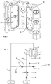
- Fig. 1 shows a representation of a forming device 50 for expanding plastic preforms to plastic containers.
- This forming device has a blow mold with a first side part 2 and a second side part 4. These two side parts can be unfolded to receive between them a plastic preform and then folded back together to pressurize this plastic preform inside the blow mold with a gaseous medium and in particular with air.
- the reference numeral 12 refers to a first side member carrier, which is intended for supporting the side part 2.
- a blow mold carrier shell 22 is arranged on this side member support 12, which in turn receives the side part 2 of the blow mold.
- the reference numeral 14 denotes a second side member carrier, to which the second side part 4 is likewise arranged over a blow mold carrier shell 24.
- These two side member supports 12, 14 can be pivoted apart and together with respect to a common shaft or axis for opening and closing the blow mold.
- Reference numerals 16 and 18 refer to two locking elements which serve to hold the blow mold in a closed state during the expansion process. In this case, the locking elements can pivot about an axis which also extends in the same direction, as well as the axis of the two side member supports 12, 14th
- Fig. 2 shows a partial view or a half of in Fig. 1 Shown here forming device 50. It can be seen here again the side member support 12, on which via the support shell 22, the side part 2 is arranged. Furthermore, one recognizes also a part of the cavity 15, within which the plastic preforms are expanded to the plastic containers, thereby more accurately expanded against a wall of the side part 2.
- Fig. 3 shows a representation of the side member support 12. It also recognizes the expansion elements 30, which serve to urge the side member support 12 and arranged on this side part apart and thus the side part 2 to the second side part 4 zuzudrnature. At the in Fig. 3 2, two such expansion elements are provided, which cause the side part arranged thereon to be urged uniformly in a resultant direction, here in a direction which runs as an angle bisector between the two expansion elements.
- Fig. 4 shows a further illustration for illustrating the device according to the invention. It can be seen here again the two side parts 2 and 4 and roughly schematically, the expansion element 30, which is also acted upon by compressed air.
- the reference numeral 10 denotes a plastic preform which can be introduced into the blow mold and the reference numeral 5 a bottom part, which closes the blow mold or its cavity at the bottom.
- the reference numeral 52 denotes a reservoir, which serves for loading the plastic preform 10 with blown air.
- a connecting line 112 is provided between the reservoir 52 and the plastic preform or a loading device such as a blowing nozzle, which acts on the plastic preform.
- the reference numeral 54 denotes a further reservoir, which serves for acting on the expansion element 30 with blown air, for which purpose again a connecting line 116 is provided.
- valves 62, 64 which are designed as check valves.
- the check valve 62 is opened and, starting from the reservoir 54, air reaches the expansion element 30 at a pressure of, for example, 5 bar.
- Reference numeral 72 denotes a pressure measuring device which measures the pressure applied to the expansion element 30.
- the reference numeral 74 designates an exhaust device such as a throttle.
- DKM pressure pad reduction
- Reference numeral 60 denotes the control means which controls the pressurization of the expansion element.
- the above-mentioned valves are components of this control device 60.
- the reference numeral 8 indicates a (only roughly schematically illustrated) loading device such as a blowing nozzle, which acts on the plastic preforms 10 with the gaseous medium.
- Fig. 5 shows a further illustration of an arrangement according to the invention.
- the representation of the actual transformation station corresponds here to in Fig. 4 shown illustration.
- the reference numeral 65 refers to a valve which serves for venting.
- the valve 66 may control the supply of compressed air from the reservoir 54
- the reference numeral 63 denotes a valve which can control the supply from the reservoir 52, which also supplies the blown air.
- Fig. 6 shows a further arrangement according to the invention.
- the control of the air which is supplied to the expansion element 30, exclusively via a valve 70, which may be in particular, but not exclusively, a so-called proportional valve.
- Fig. 7 shows a pressure curve for the expansion element.
- a pressure curve P1 is shown, which represents the pressure during the loading of the plastic preforms during the expansion process.
- the plastic preforms are first subjected to a Vorblastik, then with an intermediate blowing pressure and finally with a Fertigblastik which is held for a predetermined period of time to form the container and to keep it in this molded state.
- the reference character Tb denotes the time at which the expansion process or the pressurization of the plastic preform begins.
- Reference numerals Pe1 and Pe2 illustrate two portions of the pressure waveform applied to the expanding agent.
- the expansion element 30 is subjected to a first predetermined pressure Pe1, which is preferably constant here and is up to 7 bar, preferably about 5 bar.
- a pressure Pe2 is applied to the expansion element 30, which is adapted to the pressure P1 and corresponds thereto.
- the loading of the expansion element with the pressure Pe2 is set here again as soon as the pressure on the plastic preform lowers, so the plastic preform is relieved again. However, it would also be possible to maintain the pressure on the expansion agent until complete completion of the expansion process.
- the pressure curve in the expansion element 30 essentially follows the pressure which is applied to the plastic containers for the application or shaping of the plastic preforms. As soon as the pressure in section dT2 exceeds the pressure in section dT1, the pressure profile in the expansion element follows the pressure profile of section dT2. As soon as the pressure in the section dT2 becomes lower than the pressure in the section dT1, the pressure course in the expansion element follows that of the first section dT1.
Landscapes
- Engineering & Computer Science (AREA)
- Manufacturing & Machinery (AREA)
- Mechanical Engineering (AREA)
- Blow-Moulding Or Thermoforming Of Plastics Or The Like (AREA)
- Moulds For Moulding Plastics Or The Like (AREA)
Description
Die vorliegende Erfindung bezieht sich auf eine Vorrichtung und ein Verfahren zum Umformen von Kunststoffvorformlingen in Kunststoffbehältnisse und insbesondere in Kunststoffflaschen. Derartige Vorrichtungen und Verfahren sind aus dem Stand der Technik seit längerem bekannt. Dabei werden üblicherweise erwärmte Kunststoffvorformlinge in Blasstationen durch Beaufschlagung mit Druckluft zu Kunststoffflaschen umgeformt. Zu diesem Zweck werden die Kunststoffvorformlinge in eine Blasform eingebracht, diese anschließend geschlossen und in diesem geschlossenen Zustand erfolgt die Expansion der Kunststoffvorformlinge. Ein Problem bei dieser Umformung ist dabei oft der Übergang der beiden Blasformteile, beispielsweise Blasformhälften, der bei der Herstellung zu nicht gewollten Nähten des fertigen Behältnisses führen kann.The present invention relates to an apparatus and a method for forming plastic preforms in plastic containers and in particular in plastic bottles. Such devices and methods have been known from the prior art for some time. In this case, usually heated plastic preforms are converted into blowing stations by applying compressed air to plastic bottles. For this purpose, the plastic preforms are introduced into a blow mold, these are then closed and in this closed state, the expansion of the plastic preforms takes place. A problem with this transformation is often the transition of the two blow-molded parts, such as blow mold halves, which can lead to unwanted seams of the finished container during manufacture.
Im Stand der Technik ist es daher bekannt, bei derartigen Umformungsstationen sogenannte Druckkissen einzusetzen, welche während der Expansion des Kunststoffvorformlings die beiden Blasformteile bzw. Blasformhälften aufeinander zu pressen. Bei einer aus dem internen Stand der Technik der Anmelderin bekannten Vorgehensweise wird dabei das Druckkissen mit dem gleichen Druck beaufschlagt, der während dem Blasvorgang auch in das Behältnis geführt wird bzw. der darin vorherrscht. Der Druckverlauf in den Druckkissen entspricht damit hier dem Blasdruckverlauf. Dadurch wird das besagte Druckkissen immer nur mit dem Druck beaufschlagt, der gerade zum formspaltlosen Zuhalten der Blasform erforderlich ist. Eine darüber hinaus gehende Belastung des Formträgers tritt nicht auf. Aus der
Weiterhin ist es aus dem internen Stand der Technik der Anmelderin bekannt, eine separate Druckkissenansteuerung vorzusehen, welche bewirkt, dass das Druckkissen bereits vor dem Blasvorgang mit einem Druck beaufschlagt wird, der sogar höher ist, als der Fertigblasdruck. Der Druckkissendruck wird dabei während des gesamten Blasablaufs konstant gehalten. Diese Ausführung ist insbesondere bei großvolumigen Behältnissen relevant, bei denen die projizierte Fläche eine so große Kraft aufbauen würde, dass der Fertigblasdruck nicht mehr ausreicht, um die Formen zu- bzw. aneinanderzuhalten. Der Nachteil dieser Vorgehensweise besteht in einem höheren Energieverbrauch und auch darin, dass die Belastung des Formträgers sehr hoch ist.Furthermore, it is known from Applicant's prior art to provide a separate pressure pad driver which causes the pressure pad to be pressurized even before the blowing operation, which is even higher than the finish blow pressure. The pressure pad pressure is kept constant during the entire blowing process. This embodiment is particularly relevant in large volume containers in which the projected area would build up such a large force that the finish blow pressure is no longer sufficient to hold the molds together. The disadvantage of this approach is a higher energy consumption and also that the load on the mold carrier is very high.
Bei einer weiteren aus dem internen Stand der Technik der Anmelderin bekannten Vorgehensweise wird das Druckkissen mit einem geringeren Druck im Vergleich zu dem Fertigblasdruck betätigt. In diesem Falle spricht man auch von einer Druckkissenminderung. Das Druckkissen wird bereits vor dem Blasvorgang mit Druck beaufschlagt. Der Druckkissendruck wird weiterhin während des gesamten Blasablaufs konstant gehalten. Diese Ausführung eignet sich insbesondere bei kleinvolumigen Behältnissen, wobei hiermit auch die Belastung des Formträgers signifikant reduziert werden kann.In another approach known to the Applicant's internal art, the pressure pad is actuated at a lower pressure compared to the finish blow pressure. In this case, one speaks of a pressure pad reduction. The pressure pad is already pressurized before the blowing process. The pressure pad pressure is kept constant throughout the blowing process. This embodiment is particularly suitable for small-volume containers, whereby the burden of the mold carrier can be significantly reduced hereby.
Bei einem weiteren aus dem Stand der Technik bekannten Verfahren, bei dem der Druckverlauf des Druckkissens genau dem Blasdruckverlauf entspricht, beginnt sich das Druckkissen erst dann zu bewegen, wenn der Ausformvorgang des Behältnisses schon eingesetzt hat. Dies kann jedoch dazu führen, dass sich dann im Behältnis eine Naht bildet, da der Formspalt noch nicht geschlossen ist.In another known from the prior art method in which the pressure curve of the pressure pad exactly corresponds to the Blasdruckverlauf, the pressure pad begins to move only when the molding process of the container has already been used. However, this can lead to a seam forming in the container since the mold gap is not yet closed.
Der vorliegenden Erfindung liegt daher die Aufgabe zugrunde, einerseits weitgehend möglich eine Flaschennaht zu verhindern und daneben auch eine schonende Bewegung der Formhälften und eine geringere Belastung des Formträgers zu erreichen. Diese Aufgaben werden erfindungsgemäß durch die Gegenstände der unabhängigen Ansprüche erreicht. Vorteilhafte Ausführungsformen und Weiterbildungen sind Gegenstand der Unteransprüche.The present invention is therefore based on the object, on the one hand largely possible to prevent a bottle seam and also to achieve a gentle movement of the mold halves and a lower load on the mold carrier. These tasks will be achieved according to the invention by the subject matters of the independent claims. Advantageous embodiments and further developments are the subject of the dependent claims.
Bei einem erfindungsgemäßen Verfahren zum Umformen von Kunststoffvorformlingen und insbesondere zum Umformen von Kunststoffvorformlingen in Kunststoffbehältnisse, wie insbesondere, aber nicht ausschließlich, Kunststoffflaschen, werden die Kunststoffvorformlinge in eine Blasform eingebracht und durch die Beaufschlagung mit einem fließfähigen Medium,
welches in einen Innenraum der Kunststoffvorformlinge eingebracht wird, expandiert. Weiterhin weist die Blasform wenigstens zwei Seitenteile auf, welche während der Expansion der Kunststoffvorformlinge in ihrem Inneren einen Hohlraum ausbilden, innerhalb dessen die Kunststoffbehältnisse expandiert werden. Dabei sind weiterhin diese Seitenteile jeweils an Seitenteileträgern angeordnet, welche zum Öffnen und Schließen der Blasform bezüglich einander bewegt werden. Weiterhin weist wenigstens eine Anordnung aus einem Seitenteilträger und dem daran angeordneten Seitenteil ein durch ein gasförmiges Medium beaufschlagbares Expansionselement auf, welches bei Beaufschlagung mit dem gasförmigen Medium bewirkt, dass ein Seitenteil auf das andere Seitenteil zugestellt wird. Weiterhin werden während der Expansion der Kunststoffvorformlinge diese mit wenigstens zwei unterschiedlichen Druckniveaus beaufschlagt und diese Beaufschlagung des Kunststoffvorformlings setzt zu einem vorgegebenen Zeitpunkt ein.In a method according to the invention for shaping plastic preforms and in particular for reshaping plastic preforms into plastic containers, in particular, but not exclusively, plastic bottles, the plastic preforms are introduced into a blow mold and exposed to a flowable medium,
which is introduced into an interior of the plastic preforms expands. Furthermore, the blow mold on at least two side parts, which form during the expansion of the plastic preforms in their interior a cavity within which the plastic containers are expanded. In this case, furthermore, these side parts are each arranged on side part carriers, which are moved relative to each other for opening and closing the blow mold. Furthermore, at least one arrangement of a side member carrier and the side part arranged thereon comprises an expansible element which can be acted upon by a gaseous medium and which, when acted upon by the gaseous medium, causes one side part to be delivered to the other side part. Furthermore, during the expansion of the plastic preforms they are subjected to at least two different pressure levels and this loading of the plastic preform begins at a predetermined time.
Erfindungsgemäß wird das Expansionselement während eines ersten zeitlichen Abschnitts des Expansionsvorgangs mit einem ersten Druck beaufschlagt und während eines zweiten zeitlichen Abschnitts, der zeitlich nach dem ersten Abschnitt liegt, mit einem zweiten Druck, der größer ist als der erste Druck, wobei der erste Druck bevorzugt wenigstens zeitweise von dem momentanen Druck, mit dem der Kunststoffvorformling beaufschlagt wird, abweicht.According to the invention, the expansion element is acted upon during a first time portion of the expansion process with a first pressure and during a second time period, which is temporally after the first portion, with a second pressure which is greater than the first pressure, wherein the first pressure preferably at least temporarily deviates from the instantaneous pressure applied to the plastic preform.
Dies bedeutet, dass der erste Druck betrachtet in einem vorgegebenen Zeitfenster von dem Druck, mit dem die Kunststoffvorformlinge in diesem Zeitfenster beaufschlagt werden, abweicht. Bevorzugt liegt dieser Druck in diesem Zeitfenster höher als der Druck, mit dem der Kunststoffvorformling beaufschlagt wird. Bevorzugt wird das Expansionselement bereits mit Druck beaufschlagt, noch bevor der Kunststoffvorformling mit Druck beaufschlagt wird.This means that the first pressure deviates in a given time window from the pressure with which the plastic preforms are acted upon in this time window. This pressure is preferably higher in this time window than the pressure with which the plastic preform is applied. Preferably, the expansion element is already pressurized even before the plastic preform is pressurized.
Bevorzugt ist der Druck, mit dem das Expansionselement beaufschlagt wird, stets größer oder gleich dem Druck, mit dem der Kunststoffvorformling beaufschlagt wird. Andererseits liegt jedoch bevorzugt der Druck, mit dem das Expansionselement beaufschlagt wird, wenigstens zeitweise auch unter dem maximalen Druck mit dem der Kunststoffvorformling beaufschlagt wird.Preferably, the pressure with which the expansion element is acted upon, always greater than or equal to the pressure with which the plastic preform is acted upon. On the other hand, however, preferably the pressure with which the expansion element is acted upon, at least temporarily, under the maximum pressure with which the plastic preform is acted upon.
Damit liegt der zweite zeitliche Abschnitt nach dem vorgegebenen Zeitpunkt und auch der erste zeitliche Abschnitt liegt bevorzugt nach dem vorgegebenen Zeitpunkt. Unter dem vorgegebenen Zeit wird dabei hier derjenige Zeitpunkt verstanden, zu dem der Blasvorgang einsetzt bzw. mit der Druckbeaufschlagung der Kunststoffvorformlinge begonnen wird.Thus, the second temporal portion is after the predetermined time and also the first temporal portion is preferably after the predetermined time. Under the given Time is understood here as the time at which the blowing process begins or is started with the pressurization of the plastic preforms.
Bei dem Expansionselement handelt es sich insbesondere um das oben beschriebene Druckkissen. Dabei kann es sich um einen mit einem gasförmigen Medium und insbesondere mit Luft beaufschlagbaren Raum handeln, der sich aufgrund dieser Beaufschlagung zumindest geringfügig ausdehnt und so das eine Seitenteil auf das andere Seitenteil zubewegt bzw. zuspannt. Auf diese Weise werden vorteilhaft die beiden Seitenteile fester aneinander gepresst, um so das Entstehen von Nähten zu verhindern, bzw. zu verringern. Dabei kann dieses Expansionselement vorteilhaft in einem Bereich zwischen dem Seitenteilträger und dem diesem Seitenteilträger zugeordneten Seitenteil der Blasform angeordnet sein. Dabei wäre es zusätzlich noch möglich, dass Trägerschalen vorgesehen sind, an denen wiederum die Seitenteile angeordnet sind. Das Expansionselement ist dabei bevorzugt zwischen dem Seitenteilträger und der Trägerschale angeordnet, es wäre jedoch auch eine Anordnung zwischen der Trägerschale und dem jeweiligen Seitenteil der Blasform denkbar.The expansion element is in particular the pressure pad described above. This can be a space which can be acted upon by a gaseous medium and in particular with air, which expands at least slightly as a result of this application and thus moves or draws one side part onto the other side part. In this way, advantageously, the two side parts are pressed against each other more firmly, so as to prevent the formation of seams, or reduce. In this case, this expansion element can advantageously be arranged in a region between the side part support and the side part of the blow mold associated with this side part support. It would also be possible that carrier shells are provided, on which in turn the side parts are arranged. The expansion element is preferably arranged between the side member carrier and the carrier shell, but it would also be an arrangement between the carrier shell and the respective side part of the blow mold conceivable.
Bevorzugt werden die Kunststoffvorformlinge während ihrer Expansion transportiert. Besonders bevorzugt werden die Kunststoffvorformlinge während ihrer Expansion entlang einer Kreisbahn transportiert. Bei einem weiteren vorteilhaften Verfahren werden die Kunststoffvorformlinge zusätzlich gedehnt, indem besonders bevorzugt in die Kunststoffvorformlinge ein stangenartiger Körper, wie eine Reckstange, eingeführt wird, der die Kunststoffvorformlinge zumindest teilweise während des Expansionsvorgangs in deren Längsrichtung dehnt. Bei einem weiteren vorteilhaften Verfahren werden wenigstens zwei, insbesondere drei unterschiedliche Druckniveaus eingesetzt, um die Kunststoffvorformlinge zu expandieren. Dabei ist es möglich, dass die Kunststoffvorformlinge zunächst mit einem Vorblasdruck beaufschlagt werden, anschließend mit einem Zwischenblasdruck und schließlich mit einem Fertigblasdruck.Preferably, the plastic preforms are transported during their expansion. Particularly preferably, the plastic preforms are transported during their expansion along a circular path. In a further advantageous method, the plastic preforms are additionally stretched by inserting into the plastic preforms particularly preferably a rod-like body, such as a stretching rod, which expands the plastic preforms at least partially during the expansion process in their longitudinal direction. In a further advantageous method, at least two, in particular three different pressure levels are used to expand the plastic preforms. It is possible that the plastic preforms are first subjected to a Vorblasdruck, then with an intermediate blowing pressure and finally with a Fertigblasdruck.
Bei einem weiteren vorteilhaften Verfahren ist ein derartiges Expansionselement lediglich zwischen einem der Seitenteile und dem zugehörigen Seitenträgerteil angeordnet, nicht jedoch zwischen dem jeweils anderen Seitenteil und dem betreffenden anderen Seitenträgerteil.In a further advantageous method, such an expansion element is arranged only between one of the side parts and the associated side support part, but not between the respective other side part and the respective other side support part.
Bei einer weiteren vorteilhaften Ausführungsform ist ein Seitenteil gegenüber dem anderen um eine vorgegebene Achse schwenkbar. Vorteilhaft handelt es sich hierbei um eine Achse, welche senkrecht zu einer Transportebene der Kunststoffvorformlinge steht. Insbesondere handelt es sich dabei um eine Schwenkachse, welche vertikal verläuft.In a further advantageous embodiment, one side part is pivotable relative to the other about a predetermined axis. This is advantageously an axis which is perpendicular to a transport plane of the plastic preforms. In particular, it is a pivot axis which extends vertically.
Bei einem weiteren vorteilhaften Verfahren wird der besagte Hohlraum nicht nur durch die Seitenteile, sondern auch durch ein Bodenteil der Blasform abgeschlossen.In a further advantageous method, the said cavity is closed not only by the side parts, but also by a bottom part of the blow mold.
Bei einem weiteren vorteilhaften Verfahren werden die beiden Seitenteile miteinander verriegelt. Dabei kann ein Verriegelungsmechanismus vorgesehen sein, der zumindest zeitweise während des Expansionsvorgangs die beiden Seitenteile miteinander verriegelt.In a further advantageous method, the two side parts are locked together. In this case, a locking mechanism may be provided which locks the two side parts together at least temporarily during the expansion process.
Bei einem vorteilhaften Verfahren ist der erste Druck geringer als der der zweite Druck. Dieses bedeutet, dass das Expansionselement, das heißt das Druckkissen, zunächst mit einem geringeren Druck und anschließend - insbesondere während des Expansionsvorgangs mit einem höheren Druck beaufschlagt wird.In an advantageous method, the first pressure is less than that of the second pressure. This means that the expansion element, that is, the pressure pad, first with a lower pressure and then - especially during the expansion process is subjected to a higher pressure.
Dabei ist es möglich, dass der Druck kontinuierlich ansteigt, es wäre jedoch auch möglich, dass in zwei unterschiedlichen Druckstufen der Druck zugeführt wird. Vorteilhaft ist der zweite Druck wenigstens doppelt so groß wie der erste Druck, bevorzugt wenigstens dreimal so groß, bevorzugt wenigstens viermal so groß.It is possible that the pressure increases continuously, but it would also be possible that the pressure is supplied in two different pressure levels. Advantageously, the second pressure is at least twice as large as the first pressure, preferably at least three times as large, preferably at least four times as large.
Dabei ist es möglich, dass der erste Druck zunächst konstant gehalten wird, bevor der zweite Druck, das heißt der höhere Druck, einsetzt.It is possible that the first pressure is initially kept constant before the second pressure, that is, the higher pressure, begins.
Bei einem weiteren vorteilhaften Verfahren wird das Expansionselement bereits vor dem Beaufschlagen des Kunststoffvorformlings selbst mit Druck beaufschlagt. Dieses bedeutet, dass im Gegensatz zu aus dem Stand der Technik bekannten Verfahren das Expansionselement bzw. Druckkissen bereits mit Druck beaufschlagt wird, noch bevor der Kunststoffvorformling selbst mit Druck beaufschlagt wird. Dabei ist es vorteilhaft möglich, dass bereits vor dem Blasvorgang das Expansionselement mit einem vorzugsweise geringen und besonders bevorzugt konstanten Druck beaufschlagt wird, der die beiden Seitenteile bzw. Formhälften sanft zusammenfährt bzw. zusammendrückt.In a further advantageous method, the expansion element is already subjected to pressure before the application of the plastic preform itself. This means that, in contrast to known from the prior art method, the expansion element or pressure pad is already pressurized, even before the plastic preform itself is pressurized. It is advantageously possible that even before the blowing process, the expansion element is subjected to a preferably low and particularly preferably constant pressure, which gently collapses or compresses the two side parts or mold halves.
Weiterhin ist es denkbar, dass der Druck, mit dem das Expansionselement beaufschlagt wird, wenigstens zeitweise an den Beaufschlagungsdruck für die Kunststoffvorformlinge angepasst wird. So ist es denkbar, dass, sobald der Blasdruck diesen bereits anstehenden Druck übersteigt, der Druckverlauf in dem Expansionselement dem Blasdruckverlauf folgt, sodass nicht die Gefahr besteht, dass sich beim Ansteigen des Blasdrucks wieder ein Formspalt ergibt. Vorteilhaft wird damit auch wenigstens zeitweise ein Druck für das Expansionselement an einen Druck für die Beaufschlagung der Kunststoffvorformlinge angepasst. Es wäre jedoch auch denkbar, dass der Druck den Beaufschlagungsdruck für die Kunststoffvorformlinge gering, z.B. um bis zu 2 bar, übersteigt.Furthermore, it is conceivable that the pressure with which the expansion element is acted upon is at least temporarily adapted to the loading pressure for the plastic preforms. Thus, it is conceivable that, as soon as the blowing pressure exceeds this already existing pressure, the pressure curve in the expansion element follows the Blasdruckverlauf, so there is no risk that again results in a mold gap as the blowing pressure increases. Advantageously, therefore, a pressure for the expansion element is at least temporarily adapted to a pressure for the application of the plastic preforms. However, it would also be conceivable that the pressure low the loading pressure for the plastic preforms, e.g. by up to 2 bar, exceeds.
So wird bevorzugt das Expansionselement zunächst mit einem geringeren Druck beaufschlagt, um die Formträger bzw. die Blasstation nicht unnötig belasten zu müssen und anschließend bevorzugt der Blasdruck zur Ansteuerung des Expansionselements zugeschaltet. Vorteilhaft kann hierzu eine Oder-Schaltung verwendet werden, welche unten im Detail beschrieben ist.Thus, the expansion element is preferably first subjected to a lower pressure so as not to unnecessarily burden the mold carriers or the blowing station, and then preferably the blowing pressure is switched on to control the expansion element. Advantageously, an OR circuit can be used for this, which is described in detail below.
Diese hier beschriebene Umschaltung zwischen den beiden Druckniveaus für das Expansionselement kann dabei auch über "digital schaltende" Pneumatikventile erfolgen.This switching between the two pressure levels for the expansion element described here can also be done via "digital switching" pneumatic valves.
Bei einem weiteren bevorzugten Verfahren liegt der erste Druck zwischen 2 bar und 25 bar, bevorzugt zwischen 3 bar und 20 bar, bevorzugt zwischen 3 bar und 15 bar und besonders bevorzugt zwischen 4 bar und 10 bar. Dieses Druckniveau hat sich als besonders geeignet erwiesen, um ohne übermäßige Belastung der Blasstation bzw. der Seitenteilträger ein genügendes Zusammenführen der Seitenteile der Blasform zu ermöglichen.In a further preferred method, the first pressure is between 2 bar and 25 bar, preferably between 3 bar and 20 bar, preferably between 3 bar and 15 bar and particularly preferably between 4 bar and 10 bar. This level of pressure has been found to be particularly suitable to allow a sufficient merging of the side parts of the blow mold without undue stress on the blowing station or the side member support.
Bevorzugt ist, wie oben erwähnt, der zweite Druck ein Zwischenblas- und/oder Fertigblasdruck, mit dem der Kunststoffvorformling beaufschlagt wird. So kann der Druck für das Expansionselement in einem vorgegebenen Zeitabschnitt an den Fertigblasdruck angepasst werden.Preferably, as mentioned above, the second pressure is a Zwischenblas- and / or Fertigblasdruck, with which the plastic preform is acted upon. Thus, the pressure for the expansion element in a predetermined period of time can be adapted to the Fertigblasdruck.
Die vorliegende Erfindung ist weiterhin auf eine Umformungseinrichtung zum Umformen von Kunststoffvorformlingen zu Kunststoffbehältnissen und insbesondere Kunststoffflaschen gerichtet. Diese Umformungseinrichtung weist eine Blasform auf, welche wiederum zwei Seitenteile aufweist, die in einem geschlossenen Zustand der Blasform einen Hohlraum ausbilden, innerhalb dessen die Kunststoffvorformlinge durch Beaufschlagung mit einem fließfähigen Medium expandierbar sind. Weiterhin weist die Vorrichtung eine Beaufschlagungseinrichtung auf, welche einem Innenraum der Kunststoffvorformlinge zu deren Expansion das gasförmige Medium zuführt, wobei die Seitenteile jeweils an Seitenteilträgern angeordnet sind, die zum Öffnen und Schließen der Blasform bezüglich einander bewegbar sind. Weiterhin weist die Vorrichtung ein durch ein gasförmiges Medium beaufschlagbares Expansionselement auf, welches bei der Beaufschlagung mit einem gasförmigen Medium bewirkt, dass ein Seitenteil auf das andere Seitenteil zugestellt bzw. zugedrängt bzw. in Richtung des anderen Seitenteils vorgespannt wird.The present invention is further directed to a forming device for forming plastic preforms into plastic containers and in particular plastic bottles. This forming device has a blow mold, which in turn has two side parts which form a cavity in a closed state of the blow mold, within which the plastic preforms are expandable by exposure to a flowable medium. Furthermore, the device has a loading device, which supplies the gaseous medium to an interior of the plastic preforms for their expansion, wherein the side parts are each arranged on side member carriers, which are movable relative to each other for opening and closing the blow mold. Furthermore, the device has an expansible element which can be acted upon by a gaseous medium and which, when exposed to a gaseous medium, causes a side part to be delivered to the other side part or to be biased in the direction of the other side part.
Erfindungsgemäß weist die Umformungseinrichtung eine Steuerungseinrichtung auf, welche eine Steuerung der Zufuhr des gasförmigen Mediums an das Expansionselement ermöglicht, wobei ein Druck des an das Expansionselement zugeführten Mediums veränderbar ist und wenigstens zeitweise unter dem maximalen Druck liegt, mit dem der Kunststoffvorformling beaufschlagt wird.According to the invention, the forming device has a control device, which allows control of the supply of the gaseous medium to the expansion element, wherein a pressure of the medium supplied to the expansion element is variable and at least temporarily below the maximum pressure, which is applied to the plastic preform.
Es wird daher auch vorrichtungsseitig vorgeschlagen, dass der Druck, mit dem das Expansionselement bzw. das Druckkissen beaufschlagt wird, verändert wird, um dabei die oben erwähnten Vorteile zu erzielen. Vorteilhaft ist die Steuerungseinrichtung derart ausgeführt, dass das Expansionselement wenigstens zeitweise mit demjenigen Druck beaufschlagt wird, mit dem auch der Kunststoffvorformling beaufschlagt wird.It is therefore also proposed on the device side, that the pressure with which the expansion element or the pressure pad is acted upon, is changed in order to achieve the above-mentioned advantages. Advantageously, the control device is designed such that the expansion element is acted upon at least temporarily with that pressure, which is also applied to the plastic preform.
Bei einer bevorzugten Ausführungsform weist die Umformungseinrichtung ein erstes Reservoir auf, welches unter Druck stehendes, gasförmiges Medium bereitstellt und wenigstens zeitweise über eine Verbindungsleitung mit der Beaufschlagungseinrichtung verbunden ist. Bei diesem Reservoir kann es sich beispielsweise um einen Ringkanal handeln, der eine oder eine Vielzahl von Umformungsstationen mit dem gasförmigen Medium versorgt. Vorteilhaft weist die Vorrichtung mehrere derartiger Reservoirs auf, welche damit eine Beaufschlagung der Umformungseinrichtung mit unterschiedlichen Druckniveaus ermöglichen.In a preferred embodiment, the forming device has a first reservoir, which provides pressurized, gaseous medium and is at least temporarily connected via a connecting line with the loading device. This reservoir may, for example, be an annular channel which supplies one or a plurality of transformation stations with the gaseous medium. Advantageously, the device has a plurality of such reservoirs, which thus allow the deformation device to be acted upon at different pressure levels.
Bei einer vorteilhaften Ausführungsform weist die Umformungseinrichtung ein zweites Reservoir auf, welches unter Druck stehendes, gasförmiges Medium bereitstellt und welches wenigstens zeitweise über eine Verbindungsleitung mit dem Expansionselement verbunden ist. Es wird daher hier vorgeschlagen, dass ein eigenes Reservoir vorgesehen ist, über welches das Expansionselement mit dem gasförmigen Medium versorgt werden kann.In an advantageous embodiment, the forming device has a second reservoir, which provides pressurized, gaseous medium and which at least temporarily connected via a connecting line with the expansion element is. It is therefore proposed here that a separate reservoir is provided, via which the expansion element can be supplied with the gaseous medium.
Bei einer weiteren vorteilhaften Ausführungsform weist die oben erwähnte Steuerungseinrichtung wenigstens ein erstes Ventil auf, über welches die Zuführung des gasförmigen Mediums an das Expansionselement steuerbar ist. Vorteilhaft hat jedoch dieses Ventil keinen Einfluss auf den eigentlichen Blasvorgang, sondern bevorzugt lediglich auf die Beaufschlagung des Expansionselements mit dem gasförmigen Medium.In a further advantageous embodiment, the above-mentioned control device has at least one first valve, via which the supply of the gaseous medium to the expansion element is controllable. Advantageously, however, this valve has no effect on the actual blowing process, but preferably only on the admission of the expansion element with the gaseous medium.
Bei einer weiteren vorteilhaften Ausführungsform weist die Steuerungseinrichtung ein zweites Ventil auf, über welches die Zuführung des gasförmigen Mediums an das Expansionselement steuerbar ist, wobei vorzugsweise wenigstens eines der beiden Ventile ein Rückschlagventil ist. Vorteilhaft wäre es denkbar, dass die beiden genannten Ventile jeweils als Rückschlagventile ausgebildet sind.In a further advantageous embodiment, the control device has a second valve, via which the supply of the gaseous medium to the expansion element is controllable, wherein preferably at least one of the two valves is a check valve. Advantageously, it would be conceivable that the two said valves are each designed as check valves.
Die vorliegende Erfindung ist weiterhin auf eine Anlage zum Umformen von Kunststoffvorformlingen zu Kunststoffflaschen bzw. Kunststoffbehältnissen gerichtet. Diese Anlage weist eine Vielzahl von Umformungseinrichtungen der oben beschriebenen Art auf, wobei diese Umformungseinrichtungen an einen gemeinsamen beweglichen Träger angeordnet sind. Vorteilhaft handelt es sich bei dem beweglichen Träger um einen drehbaren Träger und insbesondere um ein sogenanntes Blasrad. Vorteilhaft sind dabei die einzelnen Umformungseinrichtungen an einem Außenumfang dieses Trägers angeordnet.The present invention is further directed to a plant for converting plastic preforms to plastic bottles or plastic containers. This system comprises a plurality of forming devices of the type described above, wherein these forming means are arranged on a common movable support. Advantageously, the movable support is a rotatable support and in particular a so-called blowing wheel. The individual forming devices are advantageously arranged on an outer circumference of this carrier.
Bei einer weiteren vorteilhaften Ausführungsform weist die Vorrichtung eine Zuführeinrichtung auf, welche die Kunststoffvorformlinge den einzelnen Umformungseinrichtungen zuführt. Vorteilhaft ist auch eine Abführeinrichtung vorgesehen, welche die Kunststoffvorformlinge von den Umformungseinrichtungen abführt.In a further advantageous embodiment, the device has a feed device which supplies the plastic preforms to the individual forming devices. Advantageously, a discharge device is provided, which discharges the plastic preforms from the forming devices.
Bei einer weiteren vorteilhaften Ausführungsform ist auch eine Erwärmungseinrichtung und insbesondere ein Ofen vorgesehen, der die Kunststoffvorformlinge vor der Zuführung an die einzelnen Umformungseinrichtungen erwärmt. Daneben kann auch eine Sterilisationseinrichtung vorgesehen sein, welche zum Sterilisieren der Kunststoffvorformlinge dient. Die Sterilisationseinrichtung kann dabei vor, in der oder nach der Erwärmungseinrichtung angeordnet sein. Bevorzugt ist die Sterilisationseinrichtung stromabwärts der Erwärmungseinrichtung angeordnet.In a further advantageous embodiment, a heating device and in particular a furnace is provided, which heats the plastic preforms before being fed to the individual forming devices. In addition, a sterilization device can also be provided which serves to sterilize the plastic preforms. The sterilization device can be arranged before, in or after the heating device be. Preferably, the sterilization device is arranged downstream of the heating device.
Weitere Vorteile und Ausführungsformen ergeben sich aus den beigefügten Zeichnungen. Darin zeigen:
- Fig. 1
- Eine Ansicht einer Umformungseinrichtung zum Umformen von Kunststoffvorformlingen zu Kunststoffbehältnissen;
- Fig. 2
- eine Teilansicht einer Hälfte der in
Fig. 1 gezeigten Umformungseinrichtung; - Fig. 3
- eine Darstellung eines Seitenteilträgerteils;
- Fig. 4
- eine blockdiagrammartige Darstellung einer erfindungsgemäßen Vorrichtung;
- Fig. 5
- eine weitere blockdiagrammartige Darstellung einer erfindungsgemäßen Vorrichtung;
- Fig. 6
- eine weitere blockdiagrammartige Darstellung einer erfindungsgemäßen Vorrichtung;
- Fig. 7
- einen Verlauf der Druckes für das Expansionselement.
- Fig. 1
- A view of a forming device for forming plastic preforms to plastic containers;
- Fig. 2
- a partial view of a half of in
Fig. 1 shown forming device; - Fig. 3
- a representation of a side member support member;
- Fig. 4
- a block diagram-like representation of a device according to the invention;
- Fig. 5
- a further block diagram-like representation of a device according to the invention;
- Fig. 6
- a further block diagram-like representation of a device according to the invention;
- Fig. 7
- a course of pressure for the expansion element.
Das Bezugszeichen 14 kennzeichnet einen zweiten Seitenteilträger, an den das zweite Seitenteil 4 ebenfalls über eine Blasformträgerschale 24 angeordnet ist. Diese beiden Seitenteilträger 12, 14 können bezüglich einer gemeinsamen Welle bzw. Achse zum Öffnen und Schließen der Blasform auseinander- und zusammengeschwenkt werden. Die Bezugszeichen 16 und 18 beziehen sich auf zwei Verriegelungselemente, welche dazu dienen, um die Blasform während des Expansionsvorgangs in einem geschlossenen Zustand zu halten. Dabei können die Verriegelungselemente um eine Achse schwenken, die sich auch in der gleichen Richtung erstreckt, wie auch die Achse der beiden Seitenteilträger 12, 14.The
Das Bezugszeichen 52 kennzeichnet ein Reservoir, welches zur Beaufschlagung des Kunststoffvorformlings 10 mit Blasluft dient. Zu diesem Zwecke ist zwischen dem Reservoir 52 und dem Kunststoffvorformling bzw. einer Beaufschlagungseinrichtung wie einer Blasdüse, welche den Kunststoffvorformling beaufschlagt, eine Verbindungsleitung 112 vorgesehen.The
Das Bezugszeichen 54 kennzeichnet ein weiteres Reservoir, welches zum Beaufschlagen des Expansionselements 30 mit Blasluft dient, wobei hierzu ebenfalls wieder eine Verbindungsleitung 116 vorgesehen ist.The
Die Steuerung der Luftzufuhr an das Expansionselement erfolgt hier unter anderem mittels zwei Ventilen 62, 64, die als Rückschlagventile ausgebildet sind. Vor dem eigentlichen Expansionsvorgang ist das Rückschlagventil 62 geöffnet und ausgehend von dem Reservoir 54 gelangt Luft mit einem Druck von beispielsweise 5 bar zu dem Expansionselement 30.The control of the air supply to the expansion element takes place here inter alia by means of two
Sobald der Blasdruck über ein bestimmtes Niveau ansteigt, gelangt er auch über das Rückschlagventil 64 zu dem Expansionselement. In diesem Falle ist es denkbar, dass durch eben diesen Druck das Rückschlagventil 62 geschlossen wird. Das Bezugszeichen 72 kennzeichnet eine Druckmesseinrichtung, welche den an dem Expansionselement 30 anliegenden Druck misst. Das Bezugszeichen 74 kennzeichnet eine Auslasseinrichtung wie etwa eine Drossel. Über ein weiteres Ventil 66 ist vorteilhaft der dem Druckkissen bzw. Expansionselement 30 zuführbare Druck steuerbar und insbesondere zu- oder abschaltbar. Dabei kann hier auch eine Druckkissenminderung (DKM) vorgesehen sein. Das Bezugszeichen 60 kennzeichnet die Steuerungseinrichtung, welche die Druckbeaufschlagung des Expansionselementes steuert. Die oben genannten Ventile sind Bestandteile dieser Steuerungseinrichtung 60. Das Bezugszeichen 8 kennzeichnet eine (nur grob schematisch dargestellte) Beaufschlagungseinrichtung wie etwa eine Blasdüse, welche die Kunststoffvorformlinge 10 mit dem gasförmigen Medium beaufschlagt.As soon as the blowing pressure rises above a certain level, it also passes via the
Die Bezugszeichen Pe1 und Pe2 veranschaulichen zwei Abschnitte des Druckverlaufs, mit dem das Expansionsmittel beaufschlagt wird. In einem ersten Zeitraum dT1 wird das Expansionselement 30 mit einem ersten vorgegebenen Druck Pe1 beaufschlagt, der hier bevorzugt konstant ist und bei bis zu 7 bar, bevorzugt bei ca. 5 bar liegt. In dem zweiten vorgegebenen Abschnitt dT2 wird an das Expansionselement 30 ein Druck Pe2 angelegt, der an den Druck P1 angepasst ist bzw. diesem entspricht. Die Beaufschlagung des Expansionselement mit dem Druck Pe2 wird hier wieder eingestellt, sobald auch der Druck auf den Kunststoffvorformling sich absenkt, also der Kunststoffvorformling wieder entlastet wird. Es wäre jedoch auch möglich, den Druck auf das Expansionsmittel bis zur vollständigen Beendigung des Expansionsprozesses aufrecht zu erhalten. Im Abschnitt dT2 folgt der Druckverlauf im Expansionselement 30 im Wesentlichen dem Druck, der für die Beaufschlagung bzw. Ausformung der Kunststoffvorformlinge zu Kunststoffbehältnissen aufgebracht wird. Sobald der Druck im Abschnitt dT2 den Druck im Abschnitt dT1 übersteigt, folgt der Druckverlauf im Expansionselement dem Druckverlauf des Abschnitts dT2. Sobald der Druck im Abschnitt dT2 geringer wird als der Druck im Abschnitt dT1, folgt der Druckverlauf im Expansionselement dem des ersten Abschnitts dT1.Reference numerals Pe1 and Pe2 illustrate two portions of the pressure waveform applied to the expanding agent. In a first time period dT1, the
Die Anmelderin behält sich vor, sämtliche in den Anmeldungsunterlagen offenbarten Merkmale als erfindungswesentlich zu beanspruchen, sofern sie einzeln oder in Kombination gegenüber dem Stand der Technik neu sind.The Applicant reserves the right to claim all features disclosed in the application documents as essential to the invention, provided they are novel individually or in combination with respect to the prior art.
- 5050
- Umformungseinrichtungshaping device
- 22
- erstes Seitenteilfirst side part
- 44
- zweites Seitenteilsecond side part
- 55
- Bodenteilthe bottom part
- 88th
- Beaufschlagungseinrichtungloading device
- 1010
- KunststoffvorformlingPlastic preform
- 1212
- erster Seitenteilträgerfirst side member carrier
- 1414
- zweiter Seitenteilträgersecond side member carrier
- 1515
- Hohlraumcavity
- 16, 1816, 18
- Verriegelungselementelocking elements
- 2222
- erste Blasformträgerschalefirst blow mold carrier shell
- 2424
- zweite Blasformträgerschalesecond blow mold carrier shell
- 3030
- Expansionselementeexpansion elements
- 5252
- Reservoirreservoir
- 5454
- weiteres Reservoiranother reservoir
- 6262
- Rückschlagventilecheck valves
- 6363
- steuerbares Ventilcontrollable valve
- 6464
- weiteres Rückschlagventilanother check valve
- 6565
- steuerbares Ventilcontrollable valve
- 6666
- weiteres Ventil / steuerbares Ventiladditional valve / controllable valve
- 7070
- Ventil / ProportionalventilValve / Proportional valve
- 7272
- DruckmesseinrichtungPressure measuring device
- 7474
- Auslasseinrichtungoutlet
- 112112
- Verbindungsleitungconnecting line
- 116116
- weitere Verbindungsleitungfurther connection line
- Pe1, Pe2Pe1, Pe2
- Abschnitte der DruckbeaufschlagungSections of the pressurization
- dT1, dT2dT1, dT2
- zeitliche Abschnitte der Druckbeaufschlagungtemporal sections of the pressurization
- TbTb
- Zeitpunkt des Beginns der Druckbeaufschlagung des KunststoffvorformlingsTime of commencement of the pressurization of the plastic preform
Claims (12)
- A method for moulding plastic preforms (10), wherein the plastic preforms (10) are introduced into a blow mould and are expanded by applying a flowable medium thereto, which is introduced into the internal space of the plastic preforms (10), wherein said blow mould includes at least two lateral parts (2, 4) which form a cavity during the expansion of the plastic preforms, within which the plastic containers are expanded, wherein said lateral parts (2, 4) are respectively provided on lateral part carriers (12, 14) that are moved relative to each other for opening and closing the blow mould, and wherein at least one arrangement of a lateral part carrier (12, 14) and the lateral part (2, 4) provided thereon has an expansion element (30) that can have a gaseous medium applied thereto, which expansion element ensures, when the gaseous medium is applied thereto, that one lateral part (2, 4) is moved towards the other lateral part (4, 2), wherein during the expansion of the plastic preforms (10), at least two different pressure levels are applied to the latter, and wherein this application of pressure onto the plastic preform (10) is started at a predetermined point in time (Tb),
characterised in that
a first pressure (Pe1) is applied to said expansion element during a first time section (dT1) of said expansion process and a second pressure (Pe2) that is greater than said first pressure (Pe1) is applied during a second time section (dT2) that follows in time after the first section (dT1), wherein the first pressure deviates, preferably at least at times, from the instantaneous pressure that is applied onto the plastic preform. - The method as claimed in claim 1,
characterised in that
the first pressure (Pe1) is lower than the second pressure (Pe2). - The method as claimed in claim 1,
characterised in that
the pressure is already applied to the expansion element (30) prior to pressure being applied to the plastic preform (10). - The method as claimed in at least one of the preceding claims,
characterised in that
the first pressure is between 2 bar and 25 bar, preferably between 3 bar and 20 bar, preferably between 3 bar and 15 bar, preferably between 4 bar and 10 bar. - The method as clamed in at least one of the preceding claims, characterised in that
the second pressure is an intermediate and/or final blowing pressure that is applied onto the plastic preform. - A moulding unit (50) for moulding plastic preforms (10) using a blow mould (2, 4) that includes two lateral parts (2, 4) which in a closed condition of said blow mould (2, 4) form a cavity (15), within which cavity the plastic preforms (10) can be expanded by applying a flowable medium thereto using an application unit that supplies the gaseous medium into the internal space of the plastic preforms (10) for the expansion thereof, wherein the lateral parts (2, 4) are each provided on lateral part carriers (12, 14) which can be moved relative to each other for opening and closing the blow mould, and wherein the apparatus (50) has an expansion element (30) that can have a gaseous medium applied thereto, which expansion element ensures, when a gaseous medium is applied thereto, that a lateral part (2, 4) is urged towards the other lateral part (4, 2),
characterised in that
the moulding unit includes a control unit (60) that allows the supply of the gaseous medium to the expansion element to be controlled, wherein a pressure of the medium supplied to the expansion element (30) can be modified and is, at least at times, below the maximum pressure that is applied to the plastic preform (10). - The moulding unit (50) as claimed in claim 6,
characterised in that
the moulding unit includes a first reservoir (52) that provides pressurised gaseous medium and that is, at least at times, connected to the application unit via a connection line (112). - The moulding unit (50) as claimed in claim 7,
characterised in that
the moulding unit (50) includes a second reservoir (54) which provides pressurised gaseous medium and which is connected, at least at times, to the expansion element (30) via a connection line (116). - The moulding unit (50) as claimed in at least one of the preceding claims 6 - 8, characterised in that
said control unit (60) includes at least one first valve (62), via which the supply of the gaseous medium to said expansion element (30) can be controlled. - The moulding unit (50) as claimed in claim 9,
characterised in that
the first valve is a proportional valve. - The moulding unit (50) as claimed in claim 9,
characterised in that
said control unit (60) includes a second valve (64), via which the supply of the gaseous medium to the expansion element can be controlled, wherein preferably at least one valve (62, 64) is a check valve. - A system for moulding plastic preforms into plastic bottles, comprising a plurality of moulding units (50) as claimed in at least one of the preceding claims 6 - 11, wherein said moulding units (50) are disposed on a common movable carrier.
Applications Claiming Priority (1)
| Application Number | Priority Date | Filing Date | Title |
|---|---|---|---|
| DE201310104995 DE102013104995A1 (en) | 2013-05-15 | 2013-05-15 | Blow molding machine with separate pressure pad control |
Publications (2)
| Publication Number | Publication Date |
|---|---|
| EP2803469A1 EP2803469A1 (en) | 2014-11-19 |
| EP2803469B1 true EP2803469B1 (en) | 2017-10-04 |
Family
ID=50732743
Family Applications (1)
| Application Number | Title | Priority Date | Filing Date |
|---|---|---|---|
| EP14001717.9A Active EP2803469B1 (en) | 2013-05-15 | 2014-05-15 | Blow-moulding machine with separate pressure pad device |
Country Status (5)
| Country | Link |
|---|---|
| US (1) | US9908279B2 (en) |
| EP (1) | EP2803469B1 (en) |
| JP (1) | JP6377949B2 (en) |
| CN (1) | CN104162973B (en) |
| DE (1) | DE102013104995A1 (en) |
Cited By (1)
| Publication number | Priority date | Publication date | Assignee | Title |
|---|---|---|---|---|
| WO2021185647A1 (en) * | 2020-03-18 | 2021-09-23 | Sidel Participations | Device and method for manufacturing a container by means of blow moulding or stretch blow moulding |
Families Citing this family (2)
| Publication number | Priority date | Publication date | Assignee | Title |
|---|---|---|---|---|
| DE102014005533B3 (en) * | 2014-04-16 | 2015-03-05 | Khs Corpoplast Gmbh | Blowing station with compressed-air-operated form-locking device and method for holding together a multi-part blow mold |
| FR3157251A1 (en) * | 2023-12-26 | 2025-06-27 | Sidel Participations | PROCESS FOR MANUFACTURING HOLLOW BODIES BY BLOW MOLDING AND BLOW MOLDING STATION |
Family Cites Families (15)
| Publication number | Priority date | Publication date | Assignee | Title |
|---|---|---|---|---|
| US6048189A (en) * | 1995-04-05 | 2000-04-11 | Japan Synthetic Rubber Co., Ltd. | Blow molding apparatus |
| IT1287480B1 (en) * | 1996-09-24 | 1998-08-06 | Unifill Int Ag | APPARATUS FOR HEATING A PAIR OF THERMOFORMABLE MATERIAL SHEETS |
| CA2239192C (en) | 1998-05-29 | 2007-07-24 | Wentworth Mould And Die Company Limited | Universal mould carrier with improved air flow compensation |
| DE19929033B4 (en) * | 1999-06-25 | 2009-05-07 | Khs Corpoplast Gmbh & Co. Kg | Device for blow molding containers |
| JP4791643B2 (en) * | 2001-03-22 | 2011-10-12 | 北海製罐株式会社 | Blow mold equipment |
| FR2841495B1 (en) * | 2002-06-27 | 2004-11-12 | Sidel Sa | DEVICE FOR MOLDING, BY BLOWING OR STRETCH-BLOWING, CONTAINERS OF THERMOPLASTIC MATERIAL |
| US6994542B2 (en) * | 2003-12-30 | 2006-02-07 | Wentworth Mold Inc. | Air flow compensation for mold carrier |
| DE102004014653B4 (en) * | 2004-03-25 | 2022-10-20 | Krones Aktiengesellschaft | Process and device for producing a particularly heat-resistant hollow body |
| DE102008018785A1 (en) | 2008-04-10 | 2009-10-15 | Khs Corpoplast Gmbh & Co. Kg | Method and apparatus for blow molding containers |
| FR2949703A1 (en) * | 2009-09-07 | 2011-03-11 | Sidel Participations | MOLDING DEVICE EQUIPPED WITH MEANS FOR FIXING A HALF-MOLD BY ATTACTION AGAINST THE BACKGROUND OF A HOUSING ASSOCIATED WITH A MOLD HOLDER |
| FR2949705B1 (en) | 2009-09-07 | 2016-09-16 | Sidel Participations | MOLDING DEVICE EQUIPPED WITH FIXING MEANS BY ATTACHING A HALF-MOLD TO A MOLD HOLDER |
| FR2963580B1 (en) * | 2010-08-03 | 2012-09-28 | Sidel Participations | FORMING MACHINE EQUIPPED WITH A MOLDING UNIT COMPRISING COMPENSATION MEANS CONTROLLED BY AUTOMATICALLY ACTUATED VALVES |
| DE102010049025A1 (en) * | 2010-10-21 | 2012-04-26 | Krones Aktiengesellschaft | Mold carrier and stretch carriage valve |
| DE102011013124A1 (en) | 2011-03-04 | 2012-09-06 | Krones Aktiengesellschaft | Sterile blow molding machine with non-sterile media supply |
| DE102011052865A1 (en) * | 2011-08-19 | 2013-02-21 | Krones Aktiengesellschaft | Device for forming plastic preforms into plastic containers with pressure pads |
-
2013
- 2013-05-15 DE DE201310104995 patent/DE102013104995A1/en not_active Withdrawn
-
2014
- 2014-05-07 JP JP2014095761A patent/JP6377949B2/en active Active
- 2014-05-08 CN CN201410193009.9A patent/CN104162973B/en active Active
- 2014-05-09 US US14/274,516 patent/US9908279B2/en active Active
- 2014-05-15 EP EP14001717.9A patent/EP2803469B1/en active Active
Non-Patent Citations (1)
| Title |
|---|
| None * |
Cited By (2)
| Publication number | Priority date | Publication date | Assignee | Title |
|---|---|---|---|---|
| WO2021185647A1 (en) * | 2020-03-18 | 2021-09-23 | Sidel Participations | Device and method for manufacturing a container by means of blow moulding or stretch blow moulding |
| FR3108268A1 (en) * | 2020-03-18 | 2021-09-24 | Sidel Participations | Device for manufacturing a container by blow molding or stretch blow molding |
Also Published As
| Publication number | Publication date |
|---|---|
| CN104162973B (en) | 2017-05-10 |
| DE102013104995A1 (en) | 2014-11-20 |
| US20140339743A1 (en) | 2014-11-20 |
| JP6377949B2 (en) | 2018-08-22 |
| US9908279B2 (en) | 2018-03-06 |
| CN104162973A (en) | 2014-11-26 |
| EP2803469A1 (en) | 2014-11-19 |
| JP2014223803A (en) | 2014-12-04 |
Similar Documents
| Publication | Publication Date | Title |
|---|---|---|
| EP1858689B1 (en) | Device for the blow-moulding of containers | |
| EP1998950B1 (en) | Process and apparatus for the blow moulding of containers using wall-thickness measurement on the moulded article | |
| WO2011023155A1 (en) | Method and device for blow molding containers | |
| DE4340290A1 (en) | Multiple use of working air | |
| EP2653290B1 (en) | Blow-moulding machine with floor cooling in the stabilisation phase | |
| EP2753465A1 (en) | Device for transporting preforms for blow molding containers | |
| DE102011015666B4 (en) | Method and device for producing containers | |
| DE102014115645A1 (en) | Method and apparatus for forming plastic preforms with cross-sectional change of a volume flow | |
| DE102012023703A1 (en) | blow molding machine | |
| EP2803469B1 (en) | Blow-moulding machine with separate pressure pad device | |
| DE202008005393U1 (en) | Device for expanding plastic containers | |
| EP2913174A1 (en) | Blow-moulding machine with centering of the blow-moulding base | |
| EP2591906B1 (en) | Blowing machine with automatic process angle optimization | |
| EP3088160B1 (en) | Method and device for reforming plastic preforms into plastic containers | |
| EP3558631B2 (en) | Method and device for blow moulding containers with a movable bottom part | |
| EP3711925A1 (en) | Blow moulding machine with dual check valve | |
| DE102009060654B4 (en) | Method and device for producing plastic bottles | |
| DE102022109817A1 (en) | Valve block | |
| EP2353842B1 (en) | Stretch blow molding machine and stretch blow molding method with counter pressure compensation. | |
| EP2845718B1 (en) | Blow-moulding machine with controlled stretching rod and blowing nozzle movement | |
| EP3978221B1 (en) | Device and method for forming plastic preforms into plastic containers with improved flush bar arrangement | |
| DE19807582A1 (en) | Blow-molding machine for production of plastic containers | |
| DE10318556A1 (en) | Method and device for blow molding containers | |
| DE102017102838A1 (en) | Apparatus and method for forming plastic preforms to plastic containers with blown by moving bottom part | |
| DE102012025788B3 (en) | Device and method for expanding plastic containers |
Legal Events
| Date | Code | Title | Description |
|---|---|---|---|
| PUAI | Public reference made under article 153(3) epc to a published international application that has entered the european phase |
Free format text: ORIGINAL CODE: 0009012 |
|
| 17P | Request for examination filed |
Effective date: 20140515 |
|
| AK | Designated contracting states |
Kind code of ref document: A1 Designated state(s): AL AT BE BG CH CY CZ DE DK EE ES FI FR GB GR HR HU IE IS IT LI LT LU LV MC MK MT NL NO PL PT RO RS SE SI SK SM TR |
|
| AX | Request for extension of the european patent |
Extension state: BA ME |
|
| R17P | Request for examination filed (corrected) |
Effective date: 20141114 |
|
| RBV | Designated contracting states (corrected) |
Designated state(s): AL AT BE BG CH CY CZ DE DK EE ES FI FR GB GR HR HU IE IS IT LI LT LU LV MC MK MT NL NO PL PT RO RS SE SI SK SM TR |
|
| GRAP | Despatch of communication of intention to grant a patent |
Free format text: ORIGINAL CODE: EPIDOSNIGR1 |
|
| RIC1 | Information provided on ipc code assigned before grant |
Ipc: B29C 49/56 20060101ALI20170112BHEP Ipc: B29C 49/48 20060101AFI20170112BHEP Ipc: B29C 49/78 20060101ALN20170112BHEP |
|
| INTG | Intention to grant announced |
Effective date: 20170125 |
|
| RIC1 | Information provided on ipc code assigned before grant |
Ipc: B29C 49/56 20060101ALI20170117BHEP Ipc: B29C 49/48 20060101AFI20170117BHEP Ipc: B29C 49/78 20060101ALN20170117BHEP |
|
| RIN1 | Information on inventor provided before grant (corrected) |
Inventor name: SPITZER, THOMAS Inventor name: LEX, PETER Inventor name: FINGER, DIETER |
|
| GRAS | Grant fee paid |
Free format text: ORIGINAL CODE: EPIDOSNIGR3 |
|
| GRAJ | Information related to disapproval of communication of intention to grant by the applicant or resumption of examination proceedings by the epo deleted |
Free format text: ORIGINAL CODE: EPIDOSDIGR1 |
|
| GRAL | Information related to payment of fee for publishing/printing deleted |
Free format text: ORIGINAL CODE: EPIDOSDIGR3 |
|
| REG | Reference to a national code |
Ref country code: DE Ref legal event code: R079 Ref document number: 502014005643 Country of ref document: DE Free format text: PREVIOUS MAIN CLASS: B29C0049560000 Ipc: B29C0049480000 |
|
| INTG | Intention to grant announced |
Effective date: 20170125 |
|
| INTC | Intention to grant announced (deleted) | ||
| GRAP | Despatch of communication of intention to grant a patent |
Free format text: ORIGINAL CODE: EPIDOSNIGR1 |
|
| RIC1 | Information provided on ipc code assigned before grant |
Ipc: B29C 49/78 20060101ALN20170707BHEP Ipc: B29C 49/56 20060101ALI20170707BHEP Ipc: B29C 49/48 20060101AFI20170707BHEP |
|
| GRAA | (expected) grant |
Free format text: ORIGINAL CODE: 0009210 |
|
| INTG | Intention to grant announced |
Effective date: 20170814 |
|
| AK | Designated contracting states |
Kind code of ref document: B1 Designated state(s): AL AT BE BG CH CY CZ DE DK EE ES FI FR GB GR HR HU IE IS IT LI LT LU LV MC MK MT NL NO PL PT RO RS SE SI SK SM TR |
|
| REG | Reference to a national code |
Ref country code: GB Ref legal event code: FG4D Free format text: NOT ENGLISH |
|
| REG | Reference to a national code |
Ref country code: CH Ref legal event code: EP |
|
| REG | Reference to a national code |
Ref country code: AT Ref legal event code: REF Ref document number: 933594 Country of ref document: AT Kind code of ref document: T Effective date: 20171015 |
|
| REG | Reference to a national code |
Ref country code: IE Ref legal event code: FG4D Free format text: LANGUAGE OF EP DOCUMENT: GERMAN |
|
| REG | Reference to a national code |
Ref country code: DE Ref legal event code: R096 Ref document number: 502014005643 Country of ref document: DE |
|
| REG | Reference to a national code |
Ref country code: NL Ref legal event code: MP Effective date: 20171004 |
|
| REG | Reference to a national code |
Ref country code: LT Ref legal event code: MG4D |
|
| PG25 | Lapsed in a contracting state [announced via postgrant information from national office to epo] |
Ref country code: NL Free format text: LAPSE BECAUSE OF FAILURE TO SUBMIT A TRANSLATION OF THE DESCRIPTION OR TO PAY THE FEE WITHIN THE PRESCRIBED TIME-LIMIT Effective date: 20171004 |
|
| REG | Reference to a national code |
Ref country code: FR Ref legal event code: PLFP Year of fee payment: 5 |
|
| PG25 | Lapsed in a contracting state [announced via postgrant information from national office to epo] |
Ref country code: NO Free format text: LAPSE BECAUSE OF FAILURE TO SUBMIT A TRANSLATION OF THE DESCRIPTION OR TO PAY THE FEE WITHIN THE PRESCRIBED TIME-LIMIT Effective date: 20180104 Ref country code: FI Free format text: LAPSE BECAUSE OF FAILURE TO SUBMIT A TRANSLATION OF THE DESCRIPTION OR TO PAY THE FEE WITHIN THE PRESCRIBED TIME-LIMIT Effective date: 20171004 Ref country code: SE Free format text: LAPSE BECAUSE OF FAILURE TO SUBMIT A TRANSLATION OF THE DESCRIPTION OR TO PAY THE FEE WITHIN THE PRESCRIBED TIME-LIMIT Effective date: 20171004 Ref country code: LT Free format text: LAPSE BECAUSE OF FAILURE TO SUBMIT A TRANSLATION OF THE DESCRIPTION OR TO PAY THE FEE WITHIN THE PRESCRIBED TIME-LIMIT Effective date: 20171004 |
|
| PG25 | Lapsed in a contracting state [announced via postgrant information from national office to epo] |
Ref country code: IS Free format text: LAPSE BECAUSE OF FAILURE TO SUBMIT A TRANSLATION OF THE DESCRIPTION OR TO PAY THE FEE WITHIN THE PRESCRIBED TIME-LIMIT Effective date: 20180204 Ref country code: GR Free format text: LAPSE BECAUSE OF FAILURE TO SUBMIT A TRANSLATION OF THE DESCRIPTION OR TO PAY THE FEE WITHIN THE PRESCRIBED TIME-LIMIT Effective date: 20180105 Ref country code: HR Free format text: LAPSE BECAUSE OF FAILURE TO SUBMIT A TRANSLATION OF THE DESCRIPTION OR TO PAY THE FEE WITHIN THE PRESCRIBED TIME-LIMIT Effective date: 20171004 Ref country code: BG Free format text: LAPSE BECAUSE OF FAILURE TO SUBMIT A TRANSLATION OF THE DESCRIPTION OR TO PAY THE FEE WITHIN THE PRESCRIBED TIME-LIMIT Effective date: 20180104 Ref country code: RS Free format text: LAPSE BECAUSE OF FAILURE TO SUBMIT A TRANSLATION OF THE DESCRIPTION OR TO PAY THE FEE WITHIN THE PRESCRIBED TIME-LIMIT Effective date: 20171004 Ref country code: LV Free format text: LAPSE BECAUSE OF FAILURE TO SUBMIT A TRANSLATION OF THE DESCRIPTION OR TO PAY THE FEE WITHIN THE PRESCRIBED TIME-LIMIT Effective date: 20171004 |
|
| REG | Reference to a national code |
Ref country code: DE Ref legal event code: R097 Ref document number: 502014005643 Country of ref document: DE |
|
| PG25 | Lapsed in a contracting state [announced via postgrant information from national office to epo] |
Ref country code: DK Free format text: LAPSE BECAUSE OF FAILURE TO SUBMIT A TRANSLATION OF THE DESCRIPTION OR TO PAY THE FEE WITHIN THE PRESCRIBED TIME-LIMIT Effective date: 20171004 Ref country code: SK Free format text: LAPSE BECAUSE OF FAILURE TO SUBMIT A TRANSLATION OF THE DESCRIPTION OR TO PAY THE FEE WITHIN THE PRESCRIBED TIME-LIMIT Effective date: 20171004 Ref country code: CZ Free format text: LAPSE BECAUSE OF FAILURE TO SUBMIT A TRANSLATION OF THE DESCRIPTION OR TO PAY THE FEE WITHIN THE PRESCRIBED TIME-LIMIT Effective date: 20171004 Ref country code: EE Free format text: LAPSE BECAUSE OF FAILURE TO SUBMIT A TRANSLATION OF THE DESCRIPTION OR TO PAY THE FEE WITHIN THE PRESCRIBED TIME-LIMIT Effective date: 20171004 |
|
| PLBE | No opposition filed within time limit |
Free format text: ORIGINAL CODE: 0009261 |
|
| STAA | Information on the status of an ep patent application or granted ep patent |
Free format text: STATUS: NO OPPOSITION FILED WITHIN TIME LIMIT |
|
| PG25 | Lapsed in a contracting state [announced via postgrant information from national office to epo] |
Ref country code: PL Free format text: LAPSE BECAUSE OF FAILURE TO SUBMIT A TRANSLATION OF THE DESCRIPTION OR TO PAY THE FEE WITHIN THE PRESCRIBED TIME-LIMIT Effective date: 20171004 Ref country code: RO Free format text: LAPSE BECAUSE OF FAILURE TO SUBMIT A TRANSLATION OF THE DESCRIPTION OR TO PAY THE FEE WITHIN THE PRESCRIBED TIME-LIMIT Effective date: 20171004 Ref country code: SM Free format text: LAPSE BECAUSE OF FAILURE TO SUBMIT A TRANSLATION OF THE DESCRIPTION OR TO PAY THE FEE WITHIN THE PRESCRIBED TIME-LIMIT Effective date: 20171004 |
|
| 26N | No opposition filed |
Effective date: 20180705 |
|
| PG25 | Lapsed in a contracting state [announced via postgrant information from national office to epo] |
Ref country code: MT Free format text: LAPSE BECAUSE OF FAILURE TO SUBMIT A TRANSLATION OF THE DESCRIPTION OR TO PAY THE FEE WITHIN THE PRESCRIBED TIME-LIMIT Effective date: 20171004 |
|
| PG25 | Lapsed in a contracting state [announced via postgrant information from national office to epo] |
Ref country code: SI Free format text: LAPSE BECAUSE OF FAILURE TO SUBMIT A TRANSLATION OF THE DESCRIPTION OR TO PAY THE FEE WITHIN THE PRESCRIBED TIME-LIMIT Effective date: 20171004 |
|
| REG | Reference to a national code |
Ref country code: CH Ref legal event code: PL |
|
| GBPC | Gb: european patent ceased through non-payment of renewal fee |
Effective date: 20180515 |
|
| REG | Reference to a national code |
Ref country code: BE Ref legal event code: MM Effective date: 20180531 |
|
| PG25 | Lapsed in a contracting state [announced via postgrant information from national office to epo] |
Ref country code: MC Free format text: LAPSE BECAUSE OF FAILURE TO SUBMIT A TRANSLATION OF THE DESCRIPTION OR TO PAY THE FEE WITHIN THE PRESCRIBED TIME-LIMIT Effective date: 20171004 |
|
| REG | Reference to a national code |
Ref country code: IE Ref legal event code: MM4A |
|
| PG25 | Lapsed in a contracting state [announced via postgrant information from national office to epo] |
Ref country code: LI Free format text: LAPSE BECAUSE OF NON-PAYMENT OF DUE FEES Effective date: 20180531 Ref country code: CH Free format text: LAPSE BECAUSE OF NON-PAYMENT OF DUE FEES Effective date: 20180531 |
|
| PG25 | Lapsed in a contracting state [announced via postgrant information from national office to epo] |
Ref country code: LU Free format text: LAPSE BECAUSE OF NON-PAYMENT OF DUE FEES Effective date: 20180515 |
|
| PG25 | Lapsed in a contracting state [announced via postgrant information from national office to epo] |
Ref country code: GB Free format text: LAPSE BECAUSE OF NON-PAYMENT OF DUE FEES Effective date: 20180515 Ref country code: IE Free format text: LAPSE BECAUSE OF NON-PAYMENT OF DUE FEES Effective date: 20180515 |
|
| PG25 | Lapsed in a contracting state [announced via postgrant information from national office to epo] |
Ref country code: BE Free format text: LAPSE BECAUSE OF NON-PAYMENT OF DUE FEES Effective date: 20180531 |
|
| PG25 | Lapsed in a contracting state [announced via postgrant information from national office to epo] |
Ref country code: ES Free format text: LAPSE BECAUSE OF FAILURE TO SUBMIT A TRANSLATION OF THE DESCRIPTION OR TO PAY THE FEE WITHIN THE PRESCRIBED TIME-LIMIT Effective date: 20171004 |
|
| PG25 | Lapsed in a contracting state [announced via postgrant information from national office to epo] |
Ref country code: TR Free format text: LAPSE BECAUSE OF FAILURE TO SUBMIT A TRANSLATION OF THE DESCRIPTION OR TO PAY THE FEE WITHIN THE PRESCRIBED TIME-LIMIT Effective date: 20171004 |
|
| PG25 | Lapsed in a contracting state [announced via postgrant information from national office to epo] |
Ref country code: PT Free format text: LAPSE BECAUSE OF FAILURE TO SUBMIT A TRANSLATION OF THE DESCRIPTION OR TO PAY THE FEE WITHIN THE PRESCRIBED TIME-LIMIT Effective date: 20171004 Ref country code: HU Free format text: LAPSE BECAUSE OF FAILURE TO SUBMIT A TRANSLATION OF THE DESCRIPTION OR TO PAY THE FEE WITHIN THE PRESCRIBED TIME-LIMIT; INVALID AB INITIO Effective date: 20140515 |
|
| PG25 | Lapsed in a contracting state [announced via postgrant information from national office to epo] |
Ref country code: CY Free format text: LAPSE BECAUSE OF FAILURE TO SUBMIT A TRANSLATION OF THE DESCRIPTION OR TO PAY THE FEE WITHIN THE PRESCRIBED TIME-LIMIT Effective date: 20171004 Ref country code: MK Free format text: LAPSE BECAUSE OF NON-PAYMENT OF DUE FEES Effective date: 20171004 |
|
| PG25 | Lapsed in a contracting state [announced via postgrant information from national office to epo] |
Ref country code: AL Free format text: LAPSE BECAUSE OF FAILURE TO SUBMIT A TRANSLATION OF THE DESCRIPTION OR TO PAY THE FEE WITHIN THE PRESCRIBED TIME-LIMIT Effective date: 20171004 |
|
| REG | Reference to a national code |
Ref country code: AT Ref legal event code: MM01 Ref document number: 933594 Country of ref document: AT Kind code of ref document: T Effective date: 20190515 |
|
| PG25 | Lapsed in a contracting state [announced via postgrant information from national office to epo] |
Ref country code: AT Free format text: LAPSE BECAUSE OF NON-PAYMENT OF DUE FEES Effective date: 20190515 |
|
| REG | Reference to a national code |
Ref country code: FR Ref legal event code: PLFP Year of fee payment: 10 |
|
| P01 | Opt-out of the competence of the unified patent court (upc) registered |
Effective date: 20230523 |
|
| PGFP | Annual fee paid to national office [announced via postgrant information from national office to epo] |
Ref country code: DE Payment date: 20250402 Year of fee payment: 12 |
|
| PGFP | Annual fee paid to national office [announced via postgrant information from national office to epo] |
Ref country code: IT Payment date: 20250422 Year of fee payment: 12 |
|
| PGFP | Annual fee paid to national office [announced via postgrant information from national office to epo] |
Ref country code: FR Payment date: 20250401 Year of fee payment: 12 |