EP2789797A1 - Rotor - Google Patents
Rotor Download PDFInfo
- Publication number
- EP2789797A1 EP2789797A1 EP13162666.5A EP13162666A EP2789797A1 EP 2789797 A1 EP2789797 A1 EP 2789797A1 EP 13162666 A EP13162666 A EP 13162666A EP 2789797 A1 EP2789797 A1 EP 2789797A1
- Authority
- EP
- European Patent Office
- Prior art keywords
- rotor
- disc
- rotor disc
- discs
- interrupted screw
- Prior art date
- Legal status (The legal status is an assumption and is not a legal conclusion. Google has not performed a legal analysis and makes no representation as to the accuracy of the status listed.)
- Granted
Links
Images


Classifications
-
- F—MECHANICAL ENGINEERING; LIGHTING; HEATING; WEAPONS; BLASTING
- F01—MACHINES OR ENGINES IN GENERAL; ENGINE PLANTS IN GENERAL; STEAM ENGINES
- F01D—NON-POSITIVE DISPLACEMENT MACHINES OR ENGINES, e.g. STEAM TURBINES
- F01D5/00—Blades; Blade-carrying members; Heating, heat-insulating, cooling or antivibration means on the blades or the members
- F01D5/02—Blade-carrying members, e.g. rotors
- F01D5/06—Rotors for more than one axial stage, e.g. of drum or multiple disc type; Details thereof, e.g. shafts, shaft connections
- F01D5/066—Connecting means for joining rotor-discs or rotor-elements together, e.g. by a central bolt, by clamps
-
- F—MECHANICAL ENGINEERING; LIGHTING; HEATING; WEAPONS; BLASTING
- F01—MACHINES OR ENGINES IN GENERAL; ENGINE PLANTS IN GENERAL; STEAM ENGINES
- F01D—NON-POSITIVE DISPLACEMENT MACHINES OR ENGINES, e.g. STEAM TURBINES
- F01D5/00—Blades; Blade-carrying members; Heating, heat-insulating, cooling or antivibration means on the blades or the members
- F01D5/02—Blade-carrying members, e.g. rotors
- F01D5/06—Rotors for more than one axial stage, e.g. of drum or multiple disc type; Details thereof, e.g. shafts, shaft connections
-
- F—MECHANICAL ENGINEERING; LIGHTING; HEATING; WEAPONS; BLASTING
- F05—INDEXING SCHEMES RELATING TO ENGINES OR PUMPS IN VARIOUS SUBCLASSES OF CLASSES F01-F04
- F05D—INDEXING SCHEME FOR ASPECTS RELATING TO NON-POSITIVE-DISPLACEMENT MACHINES OR ENGINES, GAS-TURBINES OR JET-PROPULSION PLANTS
- F05D2230/00—Manufacture
- F05D2230/60—Assembly methods
- F05D2230/61—Assembly methods using limited numbers of standard modules which can be adapted by machining
-
- Y—GENERAL TAGGING OF NEW TECHNOLOGICAL DEVELOPMENTS; GENERAL TAGGING OF CROSS-SECTIONAL TECHNOLOGIES SPANNING OVER SEVERAL SECTIONS OF THE IPC; TECHNICAL SUBJECTS COVERED BY FORMER USPC CROSS-REFERENCE ART COLLECTIONS [XRACs] AND DIGESTS
- Y10—TECHNICAL SUBJECTS COVERED BY FORMER USPC
- Y10T—TECHNICAL SUBJECTS COVERED BY FORMER US CLASSIFICATION
- Y10T29/00—Metal working
- Y10T29/49—Method of mechanical manufacture
- Y10T29/49316—Impeller making
Definitions
- the present invention relates to a rotor, for example for a gas-turbine engine. More particularly, the present invention also relates to mechanical coupling between the rotor discs of the rotor.
- State-of-the-art gas-turbines engines typically comprise three sections: A compressor, a combustor, and a turbine.
- pressure of the working medium typically air
- the compressed air then leaves the compression section and enters the combustor, where it is mixed with fuel and the combustion process takes place. After combustion, hot air leaves the combustor and is fed into the turbine.
- a gas-turbine engine comprises a rotor.
- the rotor can be assembled from discs in a stack-up operation where components such as the compressor discs and the turbine discs are connected coaxially together along the axis of rotation.
- Various ways of connecting the discs of a rotor have been put forward.
- US3976399 discloses rotor discs stacked on a central connecting rod. The rotor discs of US3976399 are held in place by half-shells which are clamped together by clamping rings.
- US3976399 also discloses heat-shrinking rotors discs onto a central connecting rod.
- US7384075 discloses threaded joints between the components of a rotor. The threaded joint is additionally secured by an anti-rotation locking mechanism.
- US5537814 and US8100666 disclose a clamping nut and a tie shaft to axially clamp a turbine disc together with other rotor components.
- US4310286 discloses bolte
- the mechanical connections between the rotor discs of a gas-turbine engine have to meet a number of conflicting technical requirements:
- the rotor of a gas-turbine engine may deflect, so the axis of rotation and the center of mass of the rotor will no longer coincide.
- the connections between the rotors discs of a gas-turbine engine shall thus be torsionally stiff.
- the connections between the rotor discs of a gas-turbine engine shall be designed for a critical speed of the rotor well above the operational speed of 1500 or 15000 rpm.
- the pressures inside the gas-turbine engine may be severe.
- the rotor of a gas-turbine engine shall be designed to withstand the corresponding stresses.
- the new stack of rotor discs shall minimize the effort involved in its fabrication.
- the fabrication of the stack of rotor discs shall minimize the use of special tools.
- the joints between rotor discs shall allow easy and effortless removal and replacement of discs when the rotor is in stationary position.
- any rotor discs shall be easily displaceable during maintenance or repair.
- the present application is oriented towards providing the aforementioned needs and towards overcoming the aforementioned difficulties.
- the present disclosure is about improved mechanical connections between the discs of a rotor.
- an interrupted screw on each side of a reciprocally connected rotor disc is proposed.
- An interrupted screw is a screw whose surface is divided longitudinally into several blank or cutaway sections. The two rotor discs are locked together by a fraction of a turn.
- the surfaces of the interrupted screw of the first rotor disc and of the reciprocally made nut of the second rotor disc align.
- the alignment of the two surfaces results in a connection that is torsionally stiff and allows for a critical speed of the rotor well above 1500 to 15000 rpm.
- the interrupted screw on each side of the reciprocally connected rotor discs can be made of the same metals. That way, corrosion issues due to the use of dissimilar metals are eliminated.
- the rotor discs can also be made of different metals, in particular of different steel alloys.
- a gas-turbine engine may require different alloys to be used for the rotor discs of the compressor and for the rotor discs of the combustor.
- the present disclosure allows rotor discs made of different metals or alloys to be connected.
- the two or more rotor discs are engaged and one rotor disc is rotated by a fraction of a turn against the other rotor disc.
- the rotation is carried out about the axis of rotation common to the two rotor discs. That axis will later become the axis of rotation of the rotor.
- yet another rotor disc is connected the stack of previously joined rotor discs by engaging said disc and the stack of rotor discs. The process continues until the assembly of the rotor is complete.
- a disc is removed from the stack of rotor discs by rotating it by a fraction of a turn. The direction of the rotation is now opposite to the direction when two discs were connected. The disc can then be removed from the remaining stack rotor discs. The process may continue until the stack of rotor discs has been completely disassembled.
- Fig. 1 gives a cut-away view of a rotor disc 1 according to the application
- the rotor disc 1 comprises a plurality of protrusions arranged along the outer circumference of the rim 3.
- the rotor disc 1 On each of its sides 4, 5, the rotor disc 1 provides an interrupted screw.
- the two interrupted screws on each side 4, 5 of the rotor disc are reciprocally made, so the interrupted screw on one side 4 of a rotor disc 1 may cooperate with the interrupted screw on the opposite side 5 of another rotor disc.
- Fig 1 shows the interrupted screw on one side 5 of the rotor disc comprises a plurality of slots 6a, 6b, 6c, 6d.
- the slots 6a, 6b, 6c, 6d are preferably arranged evenly along the inner perimeter of the rotor disc 1, so the distance between each pair of adjacent slots is the same.
- the slots 6a, 6b, 6c, 6d provide clamping surfaces 7 arranged in between the slots 6a, 6b, 6c, 6d and the rim 3.
- the slots 6a, 6b, 6c, 6d also comprise support portions 8.
- the support portions 8 carry the mechanical forces applied to the slots 6a, 6b, 6c, 6d when two rotor discs are connected and/or in-service.
- the support portions 8 of each slot 6a, 6b, 6c, 6d are made of the same material as the rim 3.
- segments 9a, 9b, 9c On the other side 4 of the rotor disc 1, segments 9a, 9b, 9c have been arranged. Each segment on one side 4 of the rotor disc 1 reciprocates with a slot on the other side 5 of the disc 1.
- the segments 9a, 9b, 9c are arranged evenly like the slots 6a, 6b, 6c, 6d on the other side 5 of the rotor disc 1.
- the segments 9a, 9b, 9c and the slots 6a, 6b, 6c, 6d are arranged so they act like plugs and sockets.
- the segments 9a, 9b, 9c can slide into the clamping surfaces 7 provided by each slot 6a, 6b, 6c, 6d.
- the clamping surfaces 7 of the slots 6a, 6b, 6c, 6d narrow towards one of their ends.
- the segments 9a, 9b, 9c narrow in the same way.
- the segments 9a, 9b, 9c can thus slide into the clamping surfaces 7 until the surfaces of the segments 9a, 9b, 9c and the surfaces of the clamping surfaces 7 engage.
- a rigid connection between two adjacent discs is formed as the segments 9a, 9b, 9c eventually get wedged inside the slots 6a, 6b, 6c, 6d.
- the disc 1 with the slots 6a, 6b, 6c, 6d is heated before the segments 9a, 9b, 9c can slide into the slots 6a, 6b, 6c, 6d.
- the material expands, so the inner diameter of each clamping surface 7 increases.
- the segments 9a, 9b, 9c may then slide into the slots 6a, 6b, 6c, 6d.
- the temperatures of the slots 6a, 6b, 6c, 6d lower after introducing the segments 9a, 9b, 9c and a rigid connection providing a rotor with torsional stiffness will be formed.
- the segments 9a, 9b, 9c will then also exert an inward force on the clamping surfaces 7 of the slots 6a, 6b, 6c, 6d.
- the inward force counter-acts the centrifugal force when the rotor disc 1 rotates as part of a rotor.
- heat treatment will not only result in torsional stiffness but also in compensation of centrifugal forces when the rotor is in service.
- clamping surfaces 7 of the slots 6a, 6b, 6c, 6d as shown on Fig 1 point outwards from the axis of rotation of the disc 1.
- the clamping surfaces 7 of the slots 6a, 6b, 6c, 6d may point inwards. This embodiment will require segments 9a, 9b, 9c whose surfaces point outwards.
- Fig. 2 provides a three-dimensional view of a rotor disc 1 according to the application.
- This three-dimensional drawing shows the rotor disc 1 of Fig 1 viewed from one of its sides 4.
- Fig 2 shows a total of six segments 9a, 9b, 9c, 9d, 9e, 9f that are arranged in an equidistant manner.
- the angle between two adjacent segments as measured from the axis of rotation of the rotor disc 1 would be 60°.
- the segments 9a, 9b, 9c, 9d, 9e, 9f shown on the present Fig 2 have got the shape of bent cylinders.
- the cross-sections of segments 9a, 9b, 9c, 9d, 9e, 9f may be triangular or square.
- Fig 3 shows a front view of the rotor disc 1 of Fig 1 .
- Fig 3 shows the rotor disc 1 of Fig 1 as viewed from its other side 5.
- Fig 3 shows a total of six slots 6a, 6b, 6c, 6d, 6e, 6f evenly distributed along the inner perimeter of the rotor disc 1.
- the slots 6a, 6b, 6c, 6d, 6e, 6f are arranged so they match with the reciprocally made segments 9a, 9b, 9c, 9d, 9e, 9f on the other side 4 of an adjacent rotor disc.
- Fig 4 shows a pair of rotor discs 1a, 1b prior to them being connected.
- the two rotor discs 1a, 1b correspond to the discs shown on Fig 1 - 3 .
- the first rotor disc 1a provides an arrangement of slots 6a, 6b, 6c that matches the arrangement of segments 9a, 9b, 9c of the second rotor disc 1b.
- the reciprocating surfaces of the discs 1a, 1b are engaged and one disc is rotated by a fraction of a turn against the other disc.
- one disc would be rotated by 60° against the other disc because there is a total six segments 9a, 9b, 9c, 9d, 9e, 9f and of six slots 6a, 6b, 6c, 6d, 6e, 6f.
- the clamping surfaces 7 of the slots 6a, 6b, 6c, 6d, 6e, 6f and the surface of the segments 9a, 9b, 9c, 9d, 9e, 9f get wedged when the discs 1a, 1b are connected.
- wedged joint between the discs 1a, 1b then essentially becomes leakage-proof.
- the process as described above is reversed. Heat treatment can be used as well.
- the disc 1a with the slots 6a, 6b, 6c, 6d, 6e, 6f will have to be heated at a faster rate than the other disc 1b.
- the two discs 1a, 1b are disconnected as soon as the heat treatment yields a gap between the surfaces of the slots 6a, 6b, 6c, 6d, 6e, 6f and the surfaces of the segments 9a, 9b, 9c, 9d, 9e, 9f.
- Induction heating may be used for the purpose of heating disc 1a faster than the other disc 1b.
- the rotor discs 1a, 1b allow for easy dismantling of a rotor, since disconnection of the rotor discs 1a, 1b only requires a reversal of the above process.
- Fig 4 shows a pair of rotor discs before being joined
- Fig 5 shows a stack of five rotor discs 1a, 1b, 1c, 1d, 1e that have been connected as described above. According to Fig 5 it is possible to connect a plurality of rotor discs with reciprocating interrupted screws on either side. The resulting stack of connected rotor discs will form a rotor that is torsionally stiff and whose critical speed is well beyond 1500 to 15000 rpm.
- Fig 5 also indicates the stack of rotor discs provides an aperture along the common central axis of the rotor discs.
- the aperture common to all rotor discs allows other elements such as shafts to be arranged inside the aperture. There is thus sufficient space inside stack of rotor discs to arrange separate shafts for the compressor and for the turbine sections of a gas-turbine engine.
- rotor discs 1a, 1b, 1c, 1d, 1e shown on Fig 5 have all got the same diameters.
- rotor discs as per this application are connected where the rotor discs differ in diameter.
- Fig 6 shows a rotor disc 1 according to another embodiment of the application.
- the rotor disc 1 of Fig 6 comprises a protruding rim 10.
- the rim 10 provides a plurality of wedges 11a, 11b, 11c, 11d, 11e, 11f, 11g, 11h arranged on its sidewall.
- the wedges 11a, 11b, 11c, 11d, 11e, 11f, 11g, 11h are arranged evenly along the perimeter of the sidewall of the outer rim 10.
- the present Fig 6 shows a total of eight wedges.
- the rim 10 and the wedges 11a, 11b, 11c, 11d, 11e, 11f, 11g, 11h form an interrupted screw just as the slots 6a, 6b, 6c, 6d, 6e, 6f of Fig 3 .
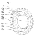
- Fig 7 shows a rotor disc 1 with an interrupted screw that reciprocates the interrupted screw shown on Fig 6 .
- the rotor disc 1 provides a groove 12 with a plurality of wedges 13a, 13b, 13c, 13d, 13e, 13f, 13g, 13h along its sidewall. Those wedges replace the segments 9a, 9b, 9c, 9d, 9e, 9f shown on Fig 2 .
- the wedges 11a, 11b, 11c, 11d, 11e, 11f, 11g, 11h of the protruding rim 10 and the wedges 13a, 13b, 13c, 13d, 13e, 13f, 13g, 13h of the groove 12 are made of the same materials. Different materials are also possible.
- Fig 8 also shows a plurality of cooling ducts 14 that penetrate either an individual rotor disc 1 or the stack of rotor discs.
- the wedged connection between rotor discs avoids welded connections between discs. Since it is no longer necessary to weld the rotor discs together, any risk of accidentally blocking the cooling duct 14 during welding is eliminated and more design flexibility of cooling channels is achieved.
- the process of connecting rotor discs continued rotor discs may be continued until a stack of rotor discs is formed.
- Fig 5 shows such a stack.
- heat treatment as explained above may be employed in order to increase the stiffness of the connection between rotor discs and utmost utilization of the material due to residual shrunk stress which acts as anti-centrifugal.
- the disclosure describes a rotor made of rotor discs with interrupted screws in relation to a gas-turbine engine.
- the same rotor and the same rotor discs form part of the rotor of a turbogenerator.
- Other applications such as hydro generators are also envisaged.
Landscapes
- Engineering & Computer Science (AREA)
- Mechanical Engineering (AREA)
- General Engineering & Computer Science (AREA)
- Turbine Rotor Nozzle Sealing (AREA)
Abstract
Description
- The present invention relates to a rotor, for example for a gas-turbine engine. More particularly, the present invention also relates to mechanical coupling between the rotor discs of the rotor.
- State-of-the-art gas-turbines engines typically comprise three sections: A compressor, a combustor, and a turbine. Before entering the combustor, pressure of the working medium, typically air, is increased to approximately by the compression section. The compressed air then leaves the compression section and enters the combustor, where it is mixed with fuel and the combustion process takes place. After combustion, hot air leaves the combustor and is fed into the turbine.
- A gas-turbine engine comprises a rotor. The rotor can be assembled from discs in a stack-up operation where components such as the compressor discs and the turbine discs are connected coaxially together along the axis of rotation. Various ways of connecting the discs of a rotor have been put forward.
US3976399 discloses rotor discs stacked on a central connecting rod. The rotor discs ofUS3976399 are held in place by half-shells which are clamped together by clamping rings.US3976399 also discloses heat-shrinking rotors discs onto a central connecting rod.US7384075 discloses threaded joints between the components of a rotor. The threaded joint is additionally secured by an anti-rotation locking mechanism.US5537814 andUS8100666 disclose a clamping nut and a tie shaft to axially clamp a turbine disc together with other rotor components.US4310286 discloses bolted joints to fixate the discs of a rotor. - The mechanical connections between the rotor discs of a gas-turbine engine have to meet a number of conflicting technical requirements: The rotor of a gas-turbine engine may deflect, so the axis of rotation and the center of mass of the rotor will no longer coincide. The connections between the rotors discs of a gas-turbine engine shall thus be torsionally stiff. The connections between the rotor discs of a gas-turbine engine shall be designed for a critical speed of the rotor well above the operational speed of 1500 or 15000 rpm.
- The pressures inside the gas-turbine engine may be severe. The rotor of a gas-turbine engine shall be designed to withstand the corresponding stresses.
- The new stack of rotor discs shall minimize the effort involved in its fabrication. In particular, the fabrication of the stack of rotor discs shall minimize the use of special tools.
- Despite the aforementioned requirement of torsional stiffness, the joints between rotor discs shall allow easy and effortless removal and replacement of discs when the rotor is in stationary position. In other words, any rotor discs shall be easily displaceable during maintenance or repair.
- The present application is oriented towards providing the aforementioned needs and towards overcoming the aforementioned difficulties.
- The present disclosure is about improved mechanical connections between the discs of a rotor. In order to arrive at a connection that is torsionally stiff and leakage-proof, an interrupted screw on each side of a reciprocally connected rotor disc is proposed. An interrupted screw is a screw whose surface is divided longitudinally into several blank or cutaway sections. The two rotor discs are locked together by a fraction of a turn.
- After connecting the two rotor discs, the surfaces of the interrupted screw of the first rotor disc and of the reciprocally made nut of the second rotor disc align. The alignment of the two surfaces results in a connection that is torsionally stiff and allows for a critical speed of the rotor well above 1500 to 15000 rpm.
- The interrupted screw on each side of the reciprocally connected rotor discs can be made of the same metals. That way, corrosion issues due to the use of dissimilar metals are eliminated.
- The rotor discs can also be made of different metals, in particular of different steel alloys. A gas-turbine engine may require different alloys to be used for the rotor discs of the compressor and for the rotor discs of the combustor. The present disclosure allows rotor discs made of different metals or alloys to be connected.
- To assemble a rotor, the two or more rotor discs are engaged and one rotor disc is rotated by a fraction of a turn against the other rotor disc. The rotation is carried out about the axis of rotation common to the two rotor discs. That axis will later become the axis of rotation of the rotor. As soon as the two discs are connected, yet another rotor disc is connected the stack of previously joined rotor discs by engaging said disc and the stack of rotor discs. The process continues until the assembly of the rotor is complete.
- Likewise, during repair or maintenance of a rotor, a disc is removed from the stack of rotor discs by rotating it by a fraction of a turn. The direction of the rotation is now opposite to the direction when two discs were connected. The disc can then be removed from the remaining stack rotor discs. The process may continue until the stack of rotor discs has been completely disassembled.
- The foregoing objects and many of the attendant advantages of this invention will become more readily appreciated as the same becomes better understood by reference to the following detailed description when taken in conjunction with the accompanying drawings, wherein:
-
Fig 1 is a cut-away view of a rotor disc according to the application. -
Fig 2 is a three-dimensional view of one side of said rotor disc. -
Fig 3 is a front view of the other side of said rotor disc. -
Fig 4 is a three-dimensional view of two rotor discs before being connected. -
Fig 5 is a three-dimensional view of a stack of rotor discs. -
Fig 6 gives a three-dimensional view of a rotor disc according to another embodiment of the invention. -
Fig 7 is a three-dimensional view of the rotor disc ofFig 6 from the other side. -
Fig 8 is a three-dimensional view of connected rotor discs as perFig 6 andFig 7 . -
Fig. 1 gives a cut-away view of arotor disc 1 according to the application Therotor disc 1 comprises a plurality of protrusions arranged along the outer circumference of therim 3. On each of itssides rotor disc 1 provides an interrupted screw. The two interrupted screws on eachside side 4 of arotor disc 1 may cooperate with the interrupted screw on theopposite side 5 of another rotor disc.Fig 1 shows the interrupted screw on oneside 5 of the rotor disc comprises a plurality ofslots rotor disc 1, so the distance between each pair of adjacent slots is the same. Theslots surfaces 7 arranged in between theslots rim 3. Theslots support portions 8. Thesupport portions 8 carry the mechanical forces applied to theslots support portions 8 of eachslot rim 3. - On the
other side 4 of therotor disc 1,segments side 4 of therotor disc 1 reciprocates with a slot on theother side 5 of thedisc 1. In a preferred embodiment, thesegments slots other side 5 of therotor disc 1. - The
segments slots segments slot slots segments segments segments segments slots - In another embodiment, the
disc 1 with theslots segments slots disc 1 with theslots surface 7 increases. Thesegments slots slots segments segments slots rotor disc 1 rotates as part of a rotor. In other words, heat treatment will not only result in torsional stiffness but also in compensation of centrifugal forces when the rotor is in service. - It should be mentioned the clamping surfaces 7 of the
slots Fig 1 point outwards from the axis of rotation of thedisc 1. In another embodiment, the clamping surfaces 7 of theslots segments -
Fig. 2 provides a three-dimensional view of arotor disc 1 according to the application. This three-dimensional drawing shows therotor disc 1 ofFig 1 viewed from one of itssides 4.Fig 2 shows a total of sixsegments rotor disc 1 would be 60°. Also, thesegments Fig 2 have got the shape of bent cylinders. In other embodiments, the cross-sections ofsegments -
Fig 3 shows a front view of therotor disc 1 ofFig 1 .Fig 3 shows therotor disc 1 ofFig 1 as viewed from itsother side 5.Fig 3 shows a total of sixslots rotor disc 1. Theslots segments other side 4 of an adjacent rotor disc. -
Fig 4 shows a pair ofrotor discs rotor discs Fig 1 - 3 . Thefirst rotor disc 1a provides an arrangement ofslots segments second rotor disc 1b. In order to connect the tworotor discs discs Fig 4 , one disc would be rotated by 60° against the other disc because there is a total sixsegments slots - The clamping surfaces 7 of the
slots segments discs discs - To disconnect the two
discs disc 1a with theslots other disc 1b. The twodiscs slots segments heating disc 1a faster than theother disc 1b. Therotor discs rotor discs - While
Fig 4 shows a pair of rotor discs before being joined,Fig 5 shows a stack of fiverotor discs Fig 5 it is possible to connect a plurality of rotor discs with reciprocating interrupted screws on either side. The resulting stack of connected rotor discs will form a rotor that is torsionally stiff and whose critical speed is well beyond 1500 to 15000 rpm. -
Fig 5 also indicates the stack of rotor discs provides an aperture along the common central axis of the rotor discs. The aperture common to all rotor discs allows other elements such as shafts to be arranged inside the aperture. There is thus sufficient space inside stack of rotor discs to arrange separate shafts for the compressor and for the turbine sections of a gas-turbine engine. - The
rotor discs Fig 5 have all got the same diameters. In another embodiment, rotor discs as per this application are connected where the rotor discs differ in diameter. -
Fig 6 shows arotor disc 1 according to another embodiment of the application. Therotor disc 1 ofFig 6 comprises a protrudingrim 10. Therim 10 provides a plurality ofwedges wedges outer rim 10. The presentFig 6 shows a total of eight wedges. Therim 10 and thewedges slots Fig 3 . -
Fig 7 shows arotor disc 1 with an interrupted screw that reciprocates the interrupted screw shown onFig 6 . Therotor disc 1 provides a groove 12 with a plurality ofwedges segments Fig 2 . In a preferred embodiment, thewedges rim 10 and thewedges - In order to connect the rotor discs shown on
Fig 6 and onFig 7 , the protrudingrim 10 ofFig 6 is introduced into the groove 12 shown onFig 7 . One of the discs is then rotated by a fraction of a turn against the other disc, until the outer surface if therim 10 and the sidewall of the groove 12 wedge. The two rotor discs are then rigidly connected.Fig 8 shows two such rotor discs after having been joined. To disconnect two rotor discs, this process is reversed. -
Fig 8 also shows a plurality ofcooling ducts 14 that penetrate either anindividual rotor disc 1 or the stack of rotor discs. The wedged connection between rotor discs avoids welded connections between discs. Since it is no longer necessary to weld the rotor discs together, any risk of accidentally blocking the coolingduct 14 during welding is eliminated and more design flexibility of cooling channels is achieved. - The process of connecting rotor discs continued rotor discs may be continued until a stack of rotor discs is formed.
Fig 5 shows such a stack. Also, heat treatment as explained above may be employed in order to increase the stiffness of the connection between rotor discs and utmost utilization of the material due to residual shrunk stress which acts as anti-centrifugal. - The disclosure describes a rotor made of rotor discs with interrupted screws in relation to a gas-turbine engine. In another embodiment, the same rotor and the same rotor discs form part of the rotor of a turbogenerator. Other applications such as hydro generators are also envisaged.
- Although the present invention has been fully described in connection with preferred embodiments, it is evident that modifications may be introduced within the scope thereof, not considering the application to be limited by these embodiments, but by the contents of the following claims.
-
- 1 rotor disc
- 1a, 1b, 1c, 1d, 1e, 1f individual rotor discs
- 2 protrusion
- 3 rim
- 4 side of a rotor disc
- 5 side of a rotor disc
- 6 slot
- 6a, 6b, 6c, 6d, 6e, 6f individual slots
- 7 clamping surface
- 8 support portion
- 9 segment
- 9a, 9b, 9c, 9d, 9e, 9f individual segments
- 10 protruding rim
- 11a, 11b, 11c, 11d, 11e, 11f, 11g, 11h wedges
- 12 groove
- 13a, 13b, 13c, 13d, 13e, 13f, 13g, 13h wedges
- 14 cooling duct
Claims (15)
- Rotor
comprising a first (1a) and
a second (1b) rotor disc,
characterized in that
the first rotor disc (1a) provides a first interrupted screw on at least one side (4),
the second rotor disc (1b) provides a second interrupted screw on at least one side (5),
the second interrupted screw of the second rotor disc (1b) is connected to the first interrupted screw of the first rotor disc (1a). - Rotor according to claim 1, characterized in that each rotor disc (1a, 1b) is substantially symmetric with respect to the axis of rotation of the rotor.
- Rotor according to claims 1 to 2, characterized in that the rotor discs (1a, 1b) are suitable to be connected directly to one another.
- Rotor according to claims 1 to 3, characterized in that at least one of the rotor discs (1a, 1b) provides two interrupted screws on both of its sides (4, 5).
- Rotor according to claims 1 to 4, characterized in that the first rotor disc (1a) provides a first interrupted screw with a protruding rim (10) with a sidewall, a first set of wedges (11a, 11b, 11c, 11d, 11e, 11 f, 11 g, 11 h) being arranged along the sidewall of the protruding rim (10), the second rotor disc (1b) provides a second interrupted screw comprising a groove (12) with a sidewall, a second set of wedges (13a, 13b, 13c, 13d, 13e, 13f, 13g, 13h) being arranged along the sidewall of the groove (12).
- Rotor according to claim 5, characterized in that
the first set of wedges (11a, 11b, 11c, 11d, 11e, 11f, 11g, 11h) is evenly arranged along the sidewall of the protruding rim (10) and the second set of wedges (13a, 13b, 13c, 13d, 13e, 13f, 13g, 13h) is evenly arranged along the sidewall of the groove (12). - Rotor according to claims 5 to 6, characterized in that
the first set of wedges (11a, 11b, 11c, 11d, 11e, 11f, 11g, 11h) comprises eight wedges and the second set of wedges (13a, 13b, 13c, 13d, 13e, 13f, 13g, 13h) comprises eight wedges. - Rotor according to claims 1 to 4, characterized in that
the first rotor disc (1a) provides an interrupted screw comprising a plurality of slots (6a, 6b, 6c, 6d, 6e, 6f), and wherein the second rotor disc (1b) provides an interrupted screw comprising a plurality of segments (9a, 9b, 9c, 9d, 9e, 9f). - Rotor according to claim 8, characterized in that
each slot (6a, 6b, 6c, 6d, 6e, 6f) comprises a clamping surface (7). - Rotor according to claims 8 to 9, characterized in that
the slots (6a, 6b, 6c, 6d, 6e, 6f) of the first rotor disc (1a) are evenly arranged along the inner perimeter of the first rotor disc (1a) and the segments (9a, 9b, 9c, 9d, 9e, 9f) of the second rotor disc (1b) are evenly arranged along the inner perimeter of the second rotor disc (1b). - Rotor according to claims 8 to 10, characterized in that
the first rotor disc (1a) provides six slots (6a, 6b, 6c, 6d, 6e, 6f) and the second rotor disc (1b) provides six segments (9a, 9b, 9c, 9d, 9e, 9f). - Gas-turbine engine with a rotor according to any of the claims 1 to 11.
- Turbogenerator with a rotor according to any of the claims 1 to 11.
- Method for directly joining a first (1a) and a second (1b) rotor disc,
characterized in that
the first rotor disc (1a) provides an interrupted screw on at least one side (4),
the second rotor disc (1b) provides an interrupted screw on at least one side (5),
the interrupted screw of the second rotor disc (1b) reciprocates the interrupted screw of the first rotor disc (1a),
the method comprising
connecting the first rotor disc (1a) with the second rotor disc (1b) by engaging the first interrupted screw of the first rotor disc (1a) with the second interrupted screw of the second rotor disc (1b),
and rotating the first rotor disc (1a) against the second rotor disc (1b) by a fraction of a turn. - Method according to claim 11, characterized in that
the size of the interrupted screw of one rotor disc (1a, 1b) is increased by heating before engaging the interrupted screws of the two rotor discs (1a, 1b).
Priority Applications (3)
| Application Number | Priority Date | Filing Date | Title |
|---|---|---|---|
| EP13162666.5A EP2789797B1 (en) | 2013-04-08 | 2013-04-08 | Rotor |
| US14/245,320 US20140301851A1 (en) | 2013-04-08 | 2014-04-04 | Rotor |
| JP2014079251A JP5855157B2 (en) | 2013-04-08 | 2014-04-08 | Rotor |
Applications Claiming Priority (1)
| Application Number | Priority Date | Filing Date | Title |
|---|---|---|---|
| EP13162666.5A EP2789797B1 (en) | 2013-04-08 | 2013-04-08 | Rotor |
Publications (2)
| Publication Number | Publication Date |
|---|---|
| EP2789797A1 true EP2789797A1 (en) | 2014-10-15 |
| EP2789797B1 EP2789797B1 (en) | 2018-08-08 |
Family
ID=48082953
Family Applications (1)
| Application Number | Title | Priority Date | Filing Date |
|---|---|---|---|
| EP13162666.5A Active EP2789797B1 (en) | 2013-04-08 | 2013-04-08 | Rotor |
Country Status (3)
| Country | Link |
|---|---|
| US (1) | US20140301851A1 (en) |
| EP (1) | EP2789797B1 (en) |
| JP (1) | JP5855157B2 (en) |
Cited By (1)
| Publication number | Priority date | Publication date | Assignee | Title |
|---|---|---|---|---|
| WO2019160575A3 (en) * | 2017-08-02 | 2019-10-17 | Siemens Aktiengesellschaft | Induction heating for assembly and disassembly of the components in a turbine engine |
Citations (8)
| Publication number | Priority date | Publication date | Assignee | Title |
|---|---|---|---|---|
| GB394001A (en) * | 1931-12-18 | 1933-06-19 | Parsons C A & Co Ltd | Improvements in and relating to built-up rotors, suitable for steam turbines |
| US2461402A (en) * | 1944-10-06 | 1949-02-08 | Power Jets Res & Dev Ltd | Rotor for multistage axial flow compressors and turbines |
| DE1801398A1 (en) * | 1968-10-02 | 1970-10-01 | Aeg Kanis Turbinen | Runner of an axial flow machine |
| US3976399A (en) | 1970-07-09 | 1976-08-24 | Kraftwerk Union Aktiengesellschaft | Rotor of disc construction for single-shaft gas turbine |
| US4310286A (en) | 1979-05-17 | 1982-01-12 | United Technologies Corporation | Rotor assembly having a multistage disk |
| US5537814A (en) | 1994-09-28 | 1996-07-23 | General Electric Company | High pressure gas generator rotor tie rod system for gas turbine engine |
| US7384075B2 (en) | 2004-05-14 | 2008-06-10 | Allison Advanced Development Company | Threaded joint for gas turbine components |
| US8100666B2 (en) | 2008-12-22 | 2012-01-24 | Pratt & Whitney Canada Corp. | Rotor mounting system for gas turbine engine |
Family Cites Families (21)
| Publication number | Priority date | Publication date | Assignee | Title |
|---|---|---|---|---|
| US1107238A (en) * | 1914-06-27 | 1914-08-11 | Gen Electric | Rotor for elastic-fluid turbines. |
| US1969431A (en) * | 1930-07-08 | 1934-08-07 | Byron Jackson Co | Safety tool joint |
| US1817808A (en) * | 1930-11-20 | 1931-08-04 | Spang Chalfant & Company Inc | Method of making tight threaded joints |
| US2284847A (en) * | 1940-04-03 | 1942-06-02 | Raymond Robert John | Photographic filter and like mount |
| US2458149A (en) * | 1944-08-23 | 1949-01-04 | United Aircraft Corp | Rotor construction for turbines |
| US2458148A (en) * | 1944-08-23 | 1949-01-04 | United Aircraft Corp | Rotor construction for turbines |
| US2479039A (en) * | 1944-11-06 | 1949-08-16 | United Aircraft Corp | Cast disk for turbine rotors |
| US2479057A (en) * | 1945-03-27 | 1949-08-16 | United Aircraft Corp | Turbine rotor |
| GB612097A (en) * | 1946-10-09 | 1948-11-08 | English Electric Co Ltd | Improvements in and relating to the cooling of gas turbine rotors |
| CH257836A (en) * | 1947-08-07 | 1948-10-31 | Sulzer Ag | Rotors for centrifugal machines, in particular for gas turbines. |
| US3094309A (en) * | 1959-12-16 | 1963-06-18 | Gen Electric | Engine rotor design |
| US3916495A (en) * | 1974-02-25 | 1975-11-04 | Gen Electric | Method and means for balancing a gas turbine engine |
| US3922009A (en) * | 1974-07-05 | 1975-11-25 | Byron Jackson Inc | Coupling |
| JPS57193701A (en) * | 1981-05-25 | 1982-11-29 | Hitachi Ltd | Stacked rotor |
| FR2667365B1 (en) * | 1990-10-02 | 1993-01-08 | Europ Propulsion | TURBINE WHEEL OF COMPOSITE MATERIAL. |
| US5338154A (en) * | 1993-03-17 | 1994-08-16 | General Electric Company | Turbine disk interstage seal axial retaining ring |
| US6572337B1 (en) * | 1999-11-30 | 2003-06-03 | General Electric Co. | Turbine rotor torque transmission |
| US6595751B1 (en) * | 2000-06-08 | 2003-07-22 | The Boeing Company | Composite rotor having recessed radial splines for high torque applications |
| SE523075C2 (en) * | 2001-11-22 | 2004-03-23 | Volvo Aero Corp | Process for producing a stator or rotor component |
| US20130302163A1 (en) * | 2010-09-15 | 2013-11-14 | Wilson Solarpower Corporation | Method and apparatus for connecting turbine rotors |
| DE102011001079A1 (en) * | 2011-03-03 | 2012-09-06 | Phoenix Contact Gmbh & Co. Kg | Connection system of a housing of a connector with a nut |
-
2013
- 2013-04-08 EP EP13162666.5A patent/EP2789797B1/en active Active
-
2014
- 2014-04-04 US US14/245,320 patent/US20140301851A1/en not_active Abandoned
- 2014-04-08 JP JP2014079251A patent/JP5855157B2/en not_active Expired - Fee Related
Patent Citations (8)
| Publication number | Priority date | Publication date | Assignee | Title |
|---|---|---|---|---|
| GB394001A (en) * | 1931-12-18 | 1933-06-19 | Parsons C A & Co Ltd | Improvements in and relating to built-up rotors, suitable for steam turbines |
| US2461402A (en) * | 1944-10-06 | 1949-02-08 | Power Jets Res & Dev Ltd | Rotor for multistage axial flow compressors and turbines |
| DE1801398A1 (en) * | 1968-10-02 | 1970-10-01 | Aeg Kanis Turbinen | Runner of an axial flow machine |
| US3976399A (en) | 1970-07-09 | 1976-08-24 | Kraftwerk Union Aktiengesellschaft | Rotor of disc construction for single-shaft gas turbine |
| US4310286A (en) | 1979-05-17 | 1982-01-12 | United Technologies Corporation | Rotor assembly having a multistage disk |
| US5537814A (en) | 1994-09-28 | 1996-07-23 | General Electric Company | High pressure gas generator rotor tie rod system for gas turbine engine |
| US7384075B2 (en) | 2004-05-14 | 2008-06-10 | Allison Advanced Development Company | Threaded joint for gas turbine components |
| US8100666B2 (en) | 2008-12-22 | 2012-01-24 | Pratt & Whitney Canada Corp. | Rotor mounting system for gas turbine engine |
Cited By (1)
| Publication number | Priority date | Publication date | Assignee | Title |
|---|---|---|---|---|
| WO2019160575A3 (en) * | 2017-08-02 | 2019-10-17 | Siemens Aktiengesellschaft | Induction heating for assembly and disassembly of the components in a turbine engine |
Also Published As
| Publication number | Publication date |
|---|---|
| EP2789797B1 (en) | 2018-08-08 |
| US20140301851A1 (en) | 2014-10-09 |
| JP2014202213A (en) | 2014-10-27 |
| JP5855157B2 (en) | 2016-02-09 |
Similar Documents
| Publication | Publication Date | Title |
|---|---|---|
| US6364634B1 (en) | Turbocharger rotor with alignment couplings | |
| EP2896784B1 (en) | Gas turbine having damping clamp | |
| US10443615B2 (en) | Alignment of flanged components | |
| US7470109B2 (en) | Machine tooled diaphragm partitions and nozzles | |
| EP2872744B1 (en) | A rotor for a radial compressor and a method for construction thereof | |
| US10280800B2 (en) | Coupling system comprising self locking joint | |
| US20120227536A1 (en) | Sectioned tuning ring for rotating body | |
| US10886797B2 (en) | Support structure segment for a generator of a wind turbine | |
| US4840026A (en) | Band clamp apparatus | |
| US4967465A (en) | Method of assembling and disassembling a rotor retaining ring system | |
| US8157519B2 (en) | Connecting system | |
| EP3094876A1 (en) | Bearing locking assemblies and methods of assembling the same | |
| EP2789797B1 (en) | Rotor | |
| EP3073056B1 (en) | Wire seal | |
| JP2013231431A (en) | Separable seal assembly for gas turbine engine | |
| EP1273815A2 (en) | Coupling arrangement | |
| US4376592A (en) | Shaft coupling | |
| CN1963158A (en) | Apparatus for channeling steam flow to turbines | |
| US10400679B2 (en) | Connection of rotatable parts | |
| EP2636845A2 (en) | Compressor/turbine rotor-torque transmission through hybrid drive | |
| EP3112598B1 (en) | Steam turbine nozzle segment for partial arc application, related assembly and steam turbine | |
| CN207620852U (en) | Baffle Assemblies with Pre-Swirlers | |
| RU2597182C2 (en) | Shaft line of turbine unit with connecting sleeves, aligned with bearing sliding supports and support or thrust bearing of this shaft line | |
| JP2015224632A (en) | Horizontal joint or the like for rotary machine, and method of assembling the same | |
| US9890660B2 (en) | Diaphragm assembly bolted joint stress reduction |
Legal Events
| Date | Code | Title | Description |
|---|---|---|---|
| PUAI | Public reference made under article 153(3) epc to a published international application that has entered the european phase |
Free format text: ORIGINAL CODE: 0009012 |
|
| 17P | Request for examination filed |
Effective date: 20130408 |
|
| AK | Designated contracting states |
Kind code of ref document: A1 Designated state(s): AL AT BE BG CH CY CZ DE DK EE ES FI FR GB GR HR HU IE IS IT LI LT LU LV MC MK MT NL NO PL PT RO RS SE SI SK SM TR |
|
| AX | Request for extension of the european patent |
Extension state: BA ME |
|
| R17P | Request for examination filed (corrected) |
Effective date: 20150413 |
|
| RBV | Designated contracting states (corrected) |
Designated state(s): AL AT BE BG CH CY CZ DE DK EE ES FI FR GB GR HR HU IE IS IT LI LT LU LV MC MK MT NL NO PL PT RO RS SE SI SK SM TR |
|
| RAP1 | Party data changed (applicant data changed or rights of an application transferred) |
Owner name: GENERAL ELECTRIC TECHNOLOGY GMBH |
|
| RAP1 | Party data changed (applicant data changed or rights of an application transferred) |
Owner name: ANSALDO ENERGIA SWITZERLAND AG |
|
| GRAP | Despatch of communication of intention to grant a patent |
Free format text: ORIGINAL CODE: EPIDOSNIGR1 |
|
| STAA | Information on the status of an ep patent application or granted ep patent |
Free format text: STATUS: GRANT OF PATENT IS INTENDED |
|
| INTG | Intention to grant announced |
Effective date: 20180228 |
|
| GRAS | Grant fee paid |
Free format text: ORIGINAL CODE: EPIDOSNIGR3 |
|
| GRAA | (expected) grant |
Free format text: ORIGINAL CODE: 0009210 |
|
| STAA | Information on the status of an ep patent application or granted ep patent |
Free format text: STATUS: THE PATENT HAS BEEN GRANTED |
|
| AK | Designated contracting states |
Kind code of ref document: B1 Designated state(s): AL AT BE BG CH CY CZ DE DK EE ES FI FR GB GR HR HU IE IS IT LI LT LU LV MC MK MT NL NO PL PT RO RS SE SI SK SM TR |
|
| REG | Reference to a national code |
Ref country code: GB Ref legal event code: FG4D |
|
| REG | Reference to a national code |
Ref country code: CH Ref legal event code: EP Ref country code: AT Ref legal event code: REF Ref document number: 1027244 Country of ref document: AT Kind code of ref document: T Effective date: 20180815 |
|
| REG | Reference to a national code |
Ref country code: IE Ref legal event code: FG4D |
|
| REG | Reference to a national code |
Ref country code: DE Ref legal event code: R096 Ref document number: 602013041473 Country of ref document: DE |
|
| REG | Reference to a national code |
Ref country code: NL Ref legal event code: MP Effective date: 20180808 |
|
| REG | Reference to a national code |
Ref country code: LT Ref legal event code: MG4D |
|
| REG | Reference to a national code |
Ref country code: AT Ref legal event code: MK05 Ref document number: 1027244 Country of ref document: AT Kind code of ref document: T Effective date: 20180808 |
|
| PG25 | Lapsed in a contracting state [announced via postgrant information from national office to epo] |
Ref country code: FI Free format text: LAPSE BECAUSE OF FAILURE TO SUBMIT A TRANSLATION OF THE DESCRIPTION OR TO PAY THE FEE WITHIN THE PRESCRIBED TIME-LIMIT Effective date: 20180808 Ref country code: IS Free format text: LAPSE BECAUSE OF FAILURE TO SUBMIT A TRANSLATION OF THE DESCRIPTION OR TO PAY THE FEE WITHIN THE PRESCRIBED TIME-LIMIT Effective date: 20181208 Ref country code: BG Free format text: LAPSE BECAUSE OF FAILURE TO SUBMIT A TRANSLATION OF THE DESCRIPTION OR TO PAY THE FEE WITHIN THE PRESCRIBED TIME-LIMIT Effective date: 20181108 Ref country code: AT Free format text: LAPSE BECAUSE OF FAILURE TO SUBMIT A TRANSLATION OF THE DESCRIPTION OR TO PAY THE FEE WITHIN THE PRESCRIBED TIME-LIMIT Effective date: 20180808 Ref country code: SE Free format text: LAPSE BECAUSE OF FAILURE TO SUBMIT A TRANSLATION OF THE DESCRIPTION OR TO PAY THE FEE WITHIN THE PRESCRIBED TIME-LIMIT Effective date: 20180808 Ref country code: NL Free format text: LAPSE BECAUSE OF FAILURE TO SUBMIT A TRANSLATION OF THE DESCRIPTION OR TO PAY THE FEE WITHIN THE PRESCRIBED TIME-LIMIT Effective date: 20180808 Ref country code: NO Free format text: LAPSE BECAUSE OF FAILURE TO SUBMIT A TRANSLATION OF THE DESCRIPTION OR TO PAY THE FEE WITHIN THE PRESCRIBED TIME-LIMIT Effective date: 20181108 Ref country code: RS Free format text: LAPSE BECAUSE OF FAILURE TO SUBMIT A TRANSLATION OF THE DESCRIPTION OR TO PAY THE FEE WITHIN THE PRESCRIBED TIME-LIMIT Effective date: 20180808 Ref country code: GR Free format text: LAPSE BECAUSE OF FAILURE TO SUBMIT A TRANSLATION OF THE DESCRIPTION OR TO PAY THE FEE WITHIN THE PRESCRIBED TIME-LIMIT Effective date: 20181109 Ref country code: LT Free format text: LAPSE BECAUSE OF FAILURE TO SUBMIT A TRANSLATION OF THE DESCRIPTION OR TO PAY THE FEE WITHIN THE PRESCRIBED TIME-LIMIT Effective date: 20180808 Ref country code: PL Free format text: LAPSE BECAUSE OF FAILURE TO SUBMIT A TRANSLATION OF THE DESCRIPTION OR TO PAY THE FEE WITHIN THE PRESCRIBED TIME-LIMIT Effective date: 20180808 |
|
| PG25 | Lapsed in a contracting state [announced via postgrant information from national office to epo] |
Ref country code: AL Free format text: LAPSE BECAUSE OF FAILURE TO SUBMIT A TRANSLATION OF THE DESCRIPTION OR TO PAY THE FEE WITHIN THE PRESCRIBED TIME-LIMIT Effective date: 20180808 Ref country code: LV Free format text: LAPSE BECAUSE OF FAILURE TO SUBMIT A TRANSLATION OF THE DESCRIPTION OR TO PAY THE FEE WITHIN THE PRESCRIBED TIME-LIMIT Effective date: 20180808 Ref country code: HR Free format text: LAPSE BECAUSE OF FAILURE TO SUBMIT A TRANSLATION OF THE DESCRIPTION OR TO PAY THE FEE WITHIN THE PRESCRIBED TIME-LIMIT Effective date: 20180808 |
|
| PG25 | Lapsed in a contracting state [announced via postgrant information from national office to epo] |
Ref country code: ES Free format text: LAPSE BECAUSE OF FAILURE TO SUBMIT A TRANSLATION OF THE DESCRIPTION OR TO PAY THE FEE WITHIN THE PRESCRIBED TIME-LIMIT Effective date: 20180808 Ref country code: IT Free format text: LAPSE BECAUSE OF FAILURE TO SUBMIT A TRANSLATION OF THE DESCRIPTION OR TO PAY THE FEE WITHIN THE PRESCRIBED TIME-LIMIT Effective date: 20180808 Ref country code: CZ Free format text: LAPSE BECAUSE OF FAILURE TO SUBMIT A TRANSLATION OF THE DESCRIPTION OR TO PAY THE FEE WITHIN THE PRESCRIBED TIME-LIMIT Effective date: 20180808 Ref country code: EE Free format text: LAPSE BECAUSE OF FAILURE TO SUBMIT A TRANSLATION OF THE DESCRIPTION OR TO PAY THE FEE WITHIN THE PRESCRIBED TIME-LIMIT Effective date: 20180808 Ref country code: RO Free format text: LAPSE BECAUSE OF FAILURE TO SUBMIT A TRANSLATION OF THE DESCRIPTION OR TO PAY THE FEE WITHIN THE PRESCRIBED TIME-LIMIT Effective date: 20180808 |
|
| REG | Reference to a national code |
Ref country code: DE Ref legal event code: R097 Ref document number: 602013041473 Country of ref document: DE |
|
| PG25 | Lapsed in a contracting state [announced via postgrant information from national office to epo] |
Ref country code: SM Free format text: LAPSE BECAUSE OF FAILURE TO SUBMIT A TRANSLATION OF THE DESCRIPTION OR TO PAY THE FEE WITHIN THE PRESCRIBED TIME-LIMIT Effective date: 20180808 Ref country code: DK Free format text: LAPSE BECAUSE OF FAILURE TO SUBMIT A TRANSLATION OF THE DESCRIPTION OR TO PAY THE FEE WITHIN THE PRESCRIBED TIME-LIMIT Effective date: 20180808 Ref country code: SK Free format text: LAPSE BECAUSE OF FAILURE TO SUBMIT A TRANSLATION OF THE DESCRIPTION OR TO PAY THE FEE WITHIN THE PRESCRIBED TIME-LIMIT Effective date: 20180808 |
|
| PLBE | No opposition filed within time limit |
Free format text: ORIGINAL CODE: 0009261 |
|
| STAA | Information on the status of an ep patent application or granted ep patent |
Free format text: STATUS: NO OPPOSITION FILED WITHIN TIME LIMIT |
|
| 26N | No opposition filed |
Effective date: 20190509 |
|
| PG25 | Lapsed in a contracting state [announced via postgrant information from national office to epo] |
Ref country code: SI Free format text: LAPSE BECAUSE OF FAILURE TO SUBMIT A TRANSLATION OF THE DESCRIPTION OR TO PAY THE FEE WITHIN THE PRESCRIBED TIME-LIMIT Effective date: 20180808 |
|
| REG | Reference to a national code |
Ref country code: CH Ref legal event code: PL |
|
| REG | Reference to a national code |
Ref country code: BE Ref legal event code: MM Effective date: 20190430 |
|
| GBPC | Gb: european patent ceased through non-payment of renewal fee |
Effective date: 20190408 |
|
| PG25 | Lapsed in a contracting state [announced via postgrant information from national office to epo] |
Ref country code: MC Free format text: LAPSE BECAUSE OF FAILURE TO SUBMIT A TRANSLATION OF THE DESCRIPTION OR TO PAY THE FEE WITHIN THE PRESCRIBED TIME-LIMIT Effective date: 20180808 Ref country code: LU Free format text: LAPSE BECAUSE OF NON-PAYMENT OF DUE FEES Effective date: 20190408 |
|
| PG25 | Lapsed in a contracting state [announced via postgrant information from national office to epo] |
Ref country code: CH Free format text: LAPSE BECAUSE OF NON-PAYMENT OF DUE FEES Effective date: 20190430 Ref country code: LI Free format text: LAPSE BECAUSE OF NON-PAYMENT OF DUE FEES Effective date: 20190430 Ref country code: GB Free format text: LAPSE BECAUSE OF NON-PAYMENT OF DUE FEES Effective date: 20190408 |
|
| PG25 | Lapsed in a contracting state [announced via postgrant information from national office to epo] |
Ref country code: BE Free format text: LAPSE BECAUSE OF NON-PAYMENT OF DUE FEES Effective date: 20190430 Ref country code: FR Free format text: LAPSE BECAUSE OF NON-PAYMENT OF DUE FEES Effective date: 20190430 |
|
| PG25 | Lapsed in a contracting state [announced via postgrant information from national office to epo] |
Ref country code: TR Free format text: LAPSE BECAUSE OF FAILURE TO SUBMIT A TRANSLATION OF THE DESCRIPTION OR TO PAY THE FEE WITHIN THE PRESCRIBED TIME-LIMIT Effective date: 20180808 |
|
| PG25 | Lapsed in a contracting state [announced via postgrant information from national office to epo] |
Ref country code: IE Free format text: LAPSE BECAUSE OF NON-PAYMENT OF DUE FEES Effective date: 20190408 |
|
| PG25 | Lapsed in a contracting state [announced via postgrant information from national office to epo] |
Ref country code: PT Free format text: LAPSE BECAUSE OF FAILURE TO SUBMIT A TRANSLATION OF THE DESCRIPTION OR TO PAY THE FEE WITHIN THE PRESCRIBED TIME-LIMIT Effective date: 20181208 |
|
| PG25 | Lapsed in a contracting state [announced via postgrant information from national office to epo] |
Ref country code: CY Free format text: LAPSE BECAUSE OF FAILURE TO SUBMIT A TRANSLATION OF THE DESCRIPTION OR TO PAY THE FEE WITHIN THE PRESCRIBED TIME-LIMIT Effective date: 20180808 |
|
| PG25 | Lapsed in a contracting state [announced via postgrant information from national office to epo] |
Ref country code: HU Free format text: LAPSE BECAUSE OF FAILURE TO SUBMIT A TRANSLATION OF THE DESCRIPTION OR TO PAY THE FEE WITHIN THE PRESCRIBED TIME-LIMIT; INVALID AB INITIO Effective date: 20130408 Ref country code: MT Free format text: LAPSE BECAUSE OF FAILURE TO SUBMIT A TRANSLATION OF THE DESCRIPTION OR TO PAY THE FEE WITHIN THE PRESCRIBED TIME-LIMIT Effective date: 20180808 |
|
| PG25 | Lapsed in a contracting state [announced via postgrant information from national office to epo] |
Ref country code: MK Free format text: LAPSE BECAUSE OF FAILURE TO SUBMIT A TRANSLATION OF THE DESCRIPTION OR TO PAY THE FEE WITHIN THE PRESCRIBED TIME-LIMIT Effective date: 20180808 |
|
| P01 | Opt-out of the competence of the unified patent court (upc) registered |
Effective date: 20240430 |
|
| PGFP | Annual fee paid to national office [announced via postgrant information from national office to epo] |
Ref country code: DE Payment date: 20250417 Year of fee payment: 13 |