EP2767528B1 - Procédé de fabrication d'une structure en nid d'abeilles céramique et structure en nid d'abeilles céramique - Google Patents
Procédé de fabrication d'une structure en nid d'abeilles céramique et structure en nid d'abeilles céramique Download PDFInfo
- Publication number
- EP2767528B1 EP2767528B1 EP12840519.8A EP12840519A EP2767528B1 EP 2767528 B1 EP2767528 B1 EP 2767528B1 EP 12840519 A EP12840519 A EP 12840519A EP 2767528 B1 EP2767528 B1 EP 2767528B1
- Authority
- EP
- European Patent Office
- Prior art keywords
- ceramic honeycomb
- peripheral
- coating material
- honeycomb body
- cells
- Prior art date
- Legal status (The legal status is an assumption and is not a legal conclusion. Google has not performed a legal analysis and makes no representation as to the accuracy of the status listed.)
- Active
Links
Images



Classifications
-
- B—PERFORMING OPERATIONS; TRANSPORTING
- B01—PHYSICAL OR CHEMICAL PROCESSES OR APPARATUS IN GENERAL
- B01D—SEPARATION
- B01D46/00—Filters or filtering processes specially modified for separating dispersed particles from gases or vapours
- B01D46/24—Particle separators, e.g. dust precipitators, using rigid hollow filter bodies
- B01D46/2403—Particle separators, e.g. dust precipitators, using rigid hollow filter bodies characterised by the physical shape or structure of the filtering element
- B01D46/2418—Honeycomb filters
- B01D46/2451—Honeycomb filters characterized by the geometrical structure, shape, pattern or configuration or parameters related to the geometry of the structure
- B01D46/2462—Honeycomb filters characterized by the geometrical structure, shape, pattern or configuration or parameters related to the geometry of the structure the outer peripheral sealing
-
- C—CHEMISTRY; METALLURGY
- C04—CEMENTS; CONCRETE; ARTIFICIAL STONE; CERAMICS; REFRACTORIES
- C04B—LIME, MAGNESIA; SLAG; CEMENTS; COMPOSITIONS THEREOF, e.g. MORTARS, CONCRETE OR LIKE BUILDING MATERIALS; ARTIFICIAL STONE; CERAMICS; REFRACTORIES; TREATMENT OF NATURAL STONE
- C04B38/00—Porous mortars, concrete, artificial stone or ceramic ware; Preparation thereof
- C04B38/0006—Honeycomb structures
- C04B38/0012—Honeycomb structures characterised by the material used for sealing or plugging (some of) the channels of the honeycombs
-
- B—PERFORMING OPERATIONS; TRANSPORTING
- B01—PHYSICAL OR CHEMICAL PROCESSES OR APPARATUS IN GENERAL
- B01D—SEPARATION
- B01D39/00—Filtering material for liquid or gaseous fluids
- B01D39/14—Other self-supporting filtering material ; Other filtering material
- B01D39/20—Other self-supporting filtering material ; Other filtering material of inorganic material, e.g. asbestos paper, metallic filtering material of non-woven wires
-
- B—PERFORMING OPERATIONS; TRANSPORTING
- B01—PHYSICAL OR CHEMICAL PROCESSES OR APPARATUS IN GENERAL
- B01D—SEPARATION
- B01D46/00—Filters or filtering processes specially modified for separating dispersed particles from gases or vapours
-
- B—PERFORMING OPERATIONS; TRANSPORTING
- B01—PHYSICAL OR CHEMICAL PROCESSES OR APPARATUS IN GENERAL
- B01D—SEPARATION
- B01D46/00—Filters or filtering processes specially modified for separating dispersed particles from gases or vapours
- B01D46/0001—Making filtering elements
-
- B—PERFORMING OPERATIONS; TRANSPORTING
- B01—PHYSICAL OR CHEMICAL PROCESSES OR APPARATUS IN GENERAL
- B01D—SEPARATION
- B01D46/00—Filters or filtering processes specially modified for separating dispersed particles from gases or vapours
- B01D46/24—Particle separators, e.g. dust precipitators, using rigid hollow filter bodies
- B01D46/2403—Particle separators, e.g. dust precipitators, using rigid hollow filter bodies characterised by the physical shape or structure of the filtering element
- B01D46/2418—Honeycomb filters
- B01D46/2451—Honeycomb filters characterized by the geometrical structure, shape, pattern or configuration or parameters related to the geometry of the structure
- B01D46/2486—Honeycomb filters characterized by the geometrical structure, shape, pattern or configuration or parameters related to the geometry of the structure characterised by the shapes or configurations
-
- B—PERFORMING OPERATIONS; TRANSPORTING
- B28—WORKING CEMENT, CLAY, OR STONE
- B28B—SHAPING CLAY OR OTHER CERAMIC COMPOSITIONS; SHAPING SLAG; SHAPING MIXTURES CONTAINING CEMENTITIOUS MATERIAL, e.g. PLASTER
- B28B11/00—Apparatus or processes for treating or working the shaped or preshaped articles
- B28B11/003—Apparatus or processes for treating or working the shaped or preshaped articles the shaping of preshaped articles, e.g. by bending
- B28B11/006—Making hollow articles or partly closed articles
-
- B—PERFORMING OPERATIONS; TRANSPORTING
- B28—WORKING CEMENT, CLAY, OR STONE
- B28B—SHAPING CLAY OR OTHER CERAMIC COMPOSITIONS; SHAPING SLAG; SHAPING MIXTURES CONTAINING CEMENTITIOUS MATERIAL, e.g. PLASTER
- B28B11/00—Apparatus or processes for treating or working the shaped or preshaped articles
- B28B11/08—Apparatus or processes for treating or working the shaped or preshaped articles for reshaping the surface, e.g. smoothing, roughening, corrugating, making screw-threads
- B28B11/0845—Apparatus or processes for treating or working the shaped or preshaped articles for reshaping the surface, e.g. smoothing, roughening, corrugating, making screw-threads for smoothing
-
- B—PERFORMING OPERATIONS; TRANSPORTING
- B28—WORKING CEMENT, CLAY, OR STONE
- B28B—SHAPING CLAY OR OTHER CERAMIC COMPOSITIONS; SHAPING SLAG; SHAPING MIXTURES CONTAINING CEMENTITIOUS MATERIAL, e.g. PLASTER
- B28B19/00—Machines or methods for applying the material to surfaces to form a permanent layer thereon
- B28B19/0038—Machines or methods for applying the material to surfaces to form a permanent layer thereon lining the outer wall of hollow objects, e.g. pipes
-
- C—CHEMISTRY; METALLURGY
- C04—CEMENTS; CONCRETE; ARTIFICIAL STONE; CERAMICS; REFRACTORIES
- C04B—LIME, MAGNESIA; SLAG; CEMENTS; COMPOSITIONS THEREOF, e.g. MORTARS, CONCRETE OR LIKE BUILDING MATERIALS; ARTIFICIAL STONE; CERAMICS; REFRACTORIES; TREATMENT OF NATURAL STONE
- C04B38/00—Porous mortars, concrete, artificial stone or ceramic ware; Preparation thereof
-
- C—CHEMISTRY; METALLURGY
- C04—CEMENTS; CONCRETE; ARTIFICIAL STONE; CERAMICS; REFRACTORIES
- C04B—LIME, MAGNESIA; SLAG; CEMENTS; COMPOSITIONS THEREOF, e.g. MORTARS, CONCRETE OR LIKE BUILDING MATERIALS; ARTIFICIAL STONE; CERAMICS; REFRACTORIES; TREATMENT OF NATURAL STONE
- C04B38/00—Porous mortars, concrete, artificial stone or ceramic ware; Preparation thereof
- C04B38/0006—Honeycomb structures
-
- C—CHEMISTRY; METALLURGY
- C04—CEMENTS; CONCRETE; ARTIFICIAL STONE; CERAMICS; REFRACTORIES
- C04B—LIME, MAGNESIA; SLAG; CEMENTS; COMPOSITIONS THEREOF, e.g. MORTARS, CONCRETE OR LIKE BUILDING MATERIALS; ARTIFICIAL STONE; CERAMICS; REFRACTORIES; TREATMENT OF NATURAL STONE
- C04B41/00—After-treatment of mortars, concrete, artificial stone or ceramics; Treatment of natural stone
- C04B41/009—After-treatment of mortars, concrete, artificial stone or ceramics; Treatment of natural stone characterised by the material treated
-
- C—CHEMISTRY; METALLURGY
- C04—CEMENTS; CONCRETE; ARTIFICIAL STONE; CERAMICS; REFRACTORIES
- C04B—LIME, MAGNESIA; SLAG; CEMENTS; COMPOSITIONS THEREOF, e.g. MORTARS, CONCRETE OR LIKE BUILDING MATERIALS; ARTIFICIAL STONE; CERAMICS; REFRACTORIES; TREATMENT OF NATURAL STONE
- C04B41/00—After-treatment of mortars, concrete, artificial stone or ceramics; Treatment of natural stone
- C04B41/45—Coating or impregnating, e.g. injection in masonry, partial coating of green or fired ceramics, organic coating compositions for adhering together two concrete elements
- C04B41/50—Coating or impregnating, e.g. injection in masonry, partial coating of green or fired ceramics, organic coating compositions for adhering together two concrete elements with inorganic materials
- C04B41/5076—Coating or impregnating, e.g. injection in masonry, partial coating of green or fired ceramics, organic coating compositions for adhering together two concrete elements with inorganic materials with masses bonded by inorganic cements
- C04B41/5089—Silica sols, alkyl, ammonium or alkali metal silicate cements
-
- C—CHEMISTRY; METALLURGY
- C04—CEMENTS; CONCRETE; ARTIFICIAL STONE; CERAMICS; REFRACTORIES
- C04B—LIME, MAGNESIA; SLAG; CEMENTS; COMPOSITIONS THEREOF, e.g. MORTARS, CONCRETE OR LIKE BUILDING MATERIALS; ARTIFICIAL STONE; CERAMICS; REFRACTORIES; TREATMENT OF NATURAL STONE
- C04B41/00—After-treatment of mortars, concrete, artificial stone or ceramics; Treatment of natural stone
- C04B41/80—After-treatment of mortars, concrete, artificial stone or ceramics; Treatment of natural stone of only ceramics
- C04B41/81—Coating or impregnation
- C04B41/85—Coating or impregnation with inorganic materials
-
- C—CHEMISTRY; METALLURGY
- C04—CEMENTS; CONCRETE; ARTIFICIAL STONE; CERAMICS; REFRACTORIES
- C04B—LIME, MAGNESIA; SLAG; CEMENTS; COMPOSITIONS THEREOF, e.g. MORTARS, CONCRETE OR LIKE BUILDING MATERIALS; ARTIFICIAL STONE; CERAMICS; REFRACTORIES; TREATMENT OF NATURAL STONE
- C04B2111/00—Mortars, concrete or artificial stone or mixtures to prepare them, characterised by specific function, property or use
- C04B2111/00474—Uses not provided for elsewhere in C04B2111/00
- C04B2111/0081—Uses not provided for elsewhere in C04B2111/00 as catalysts or catalyst carriers
-
- Y—GENERAL TAGGING OF NEW TECHNOLOGICAL DEVELOPMENTS; GENERAL TAGGING OF CROSS-SECTIONAL TECHNOLOGIES SPANNING OVER SEVERAL SECTIONS OF THE IPC; TECHNICAL SUBJECTS COVERED BY FORMER USPC CROSS-REFERENCE ART COLLECTIONS [XRACs] AND DIGESTS
- Y10—TECHNICAL SUBJECTS COVERED BY FORMER USPC
- Y10T—TECHNICAL SUBJECTS COVERED BY FORMER US CLASSIFICATION
- Y10T428/00—Stock material or miscellaneous articles
- Y10T428/24—Structurally defined web or sheet [e.g., overall dimension, etc.]
- Y10T428/24149—Honeycomb-like
- Y10T428/24157—Filled honeycomb cells [e.g., solid substance in cavities, etc.]
Definitions
- the present invention relates to a method for producing a ceramic honeycomb structure used for cleaning an exhaust gas discharged from internal combustion engines of automobiles, etc., and a ceramic honeycomb structure.
- exhaust-gas-cleaning catalyst converters and particulate-capturing filters constituted by ceramic honeycomb structures are used.
- a ceramic honeycomb structure 50 comprises a ceramic honeycomb body 51 having large numbers of longitudinal cells 54 partitioned by porous cell walls 53, and a peripheral wall 52 formed on a periphery of the ceramic honeycomb body 51, with a substantially circular or ellipsoidal cross section perpendicular to its flow paths [see Fig. 12(b) ].
- the ceramic honeycomb structure 50 is assembled in a metal container (not shown), in which it is fixed in a holding member (not shown) formed by a metal mesh or ceramic mat, etc. Accordingly, the peripheral wall should have enough strength to withstand heat shock under a load by the holding member.
- JP 05-269388 A discloses, as shown in Figs. 13(a) and 13(b) , a ceramic honeycomb structure 50 comprising a ceramic honeycomb body 51 having large numbers of longitudinal cells 54 partitioned by porous cell walls 53 and longitudinal open grooves 56 on a peripheral surface 51a, and a peripheral wall 52 formed by a coating material filled in the grooves 56.
- This ceramic honeycomb structure 50 is produced by forming a sintered ceramic honeycomb body integral with a peripheral wall by a known method, removing peripheral cells by grinding to form a ceramic honeycomb body having grooves on the peripheral surface, filling the grooves 56 of the ceramic honeycomb body with a coating material paste 57 comprising ceramic particles and/or ceramic fibers and colloidal silica or colloidal alumina and drying it to form the peripheral wall 52.
- JP 05-269388 A describes that such method produces a ceramic honeycomb structure having a reinforced peripheral portion, with excellent heat resistance and heat shock resistance.
- JP 05-269388 A describes that the coating material 57 filled in the grooves 56 on the periphery was left in the air for 24 hours, and then heated for drying at 90°C for 2 hours. To improve production efficiency, it is tried to rapidly dry the coating material by a hot-air drying furnace, microwave, etc. However, when introduced into a high-temperature (80°C or higher) hot-air drying furnace, or when high-power microwave drying starts, extreme temperature difference rapidly occurs between the ceramic honeycomb body 51 and the peripheral wall 52. By thermal stress (heat shock) generated at this time, gaps are formed in a boundary between the grooves 56 of the ceramic honeycomb body 51 and end portions of the peripheral wall 52.
- thermal stress heat shock
- gaps in the end portions of the peripheral wall of the ceramic honeycomb structure act as sites, from which the end portions of the peripheral wall are peeled and chipped, resulting in the breakage of the peripheral wall, making the ceramic honeycomb structure unusable.
- WO 07/148764 discloses, as shown in Fig. 15(a) , a ceramic honeycomb structure 60 comprising a ceramic honeycomb body 61, and a peripheral wall 62 comprising a peripheral coating portion 63 covering a peripheral surface 61a of the ceramic honeycomb body 61, and extensions 64 projecting outward from end surfaces 65a, 65b of the ceramic honeycomb body 61 for covering peripheral portions of the end surfaces 65a, 65b.
- Fig. 15(a) a ceramic honeycomb structure 60 comprising a ceramic honeycomb body 61, and a peripheral wall 62 comprising a peripheral coating portion 63 covering a peripheral surface 61a of the ceramic honeycomb body 61, and extensions 64 projecting outward from end surfaces 65a, 65b of the ceramic honeycomb body 61 for covering peripheral portions of the end surfaces 65a, 65b.
- the ceramic honeycomb structure 60 described in WO 07/148764 is produced by sandwiching both end surfaces 65a, 65b of the ceramic honeycomb body 61 by two holding members 69a, 69b such that a peripheral portion of at least one end surface 65a, 65b is open, applying a coating material 67 by a scraper 68 to the peripheral surface 61a and peripheral portions of the end surfaces 65a, 65b to form the peripheral coating portion 63 and the extensions 64, and then drying and if necessary, sintering them.
- WO 07/148764 describes that this method can effectively prevent the breakage and peeling of the peripheral wall 62.
- WO 07/148764 describes that to prevent the peripheral coating layer from being cracked by drying, the coating material is preferably dried by a combination of hot-air drying at 100-200°C and static drying with an electric heater, far-infrared rays, etc.; and that a drying speed is preferably adjusted by moisturizing.
- the coating material 67 is rapidly dried by a hot-air drying furnace, microwave, etc.
- WO 08/117729 A discloses, as shown in Fig. 16(a) , a ceramic honeycomb structure 70 comprising a ceramic honeycomb body 71 having a peripheral wall 73 longitudinally longer than the ceramic honeycomb body 71, and peripheral walls 74 in peripheral portions of end surfaces 75a, 75b of the ceramic honeycomb body 71.
- WO 08/117729 A describes that the peripheral walls 74 formed in the peripheral portions of the end surfaces are preferably removed from the end surfaces of the ceramic honeycomb body 71 after drying as shown in Fig. 16(b) .
- WO 08/117729 A describes that the ceramic honeycomb structure 70 is produced by drying a coating material 77 applied to a peripheral surface 71a and peripheral portions of the end surfaces 75a, 75b, and that because the peripheral wall 73 is longitudinally longer than the ceramic honeycomb body 71, gaps are not generated in a boundary between the peripheral surface 71a and the coating material 77 by drying, avoiding chipping in the peripheral wall due to shock, etc.
- JP 2003-284923 A discloses, as shown in Fig. 17 , a ceramic honeycomb structure 80 comprising a ceramic honeycomb body 81, in which predetermined numbers of outermost cells and cells inside therefrom are each sealed in at least one end portion and/or an intermediate portion by a peripheral wall 82, to constitute a sealed-cell portion 84 through which a fluid does not flow.
- JP 2003-284923 A describes that this ceramic honeycomb structure 80 is produced by drying and sintering an extruded honeycomb-structured green body with different shrinkage ratios between both end portions to from a frustoconical ceramic honeycomb body, machining a frustoconical peripheral surface portion of the ceramic honeycomb body to a cylindrical shape, forming the peripheral wall 82 on the peripheral surface 81a, and drying it.
- JP 2003-284923 A describes that the honeycomb structure 80 produced by this method has a heat insulation function by the sealed-cell portion 84 formed by the peripheral wall 82, enjoying a short temperature-elevating time from the start of operation, so that the activity of a catalyst carried can be enhanced in a short period of time.
- Document US 2004/0071932 A1 discloses an exhaust gas purifying filter comprising a ceramic honeycomb structure having a surrounding wall, partition walls provided in a honeycomb pattern within the surrounding wall, and a plurality of cells partitioned by the partition walls and penetrating through end faces of the structure.
- an object of the present invention is to solve the above problems, providing a method for producing a ceramic honeycomb structure comprising the steps of applying a coating material to a peripheral surface of a ceramic honeycomb body, which has longitudinal grooves, to form a peripheral wall, without generating gaps between end portions of the peripheral wall and the grooves on the peripheral surface even under heat shock in drying in a hot air drying furnace, by microwave, etc., and a ceramic honeycomb structure not suffering the peeling of end portions of the peripheral wall, in subsequent handling and use in a metal container.
- the inventors have found that in addition to a coating material applied to a peripheral surface of a ceramic honeycomb body, which has longitudinal grooves, to form a peripheral wall, when the coating material is applied to peripheral portions of both end surfaces of the ceramic honeycomb body, and inserted into peripheral cells such that it remains on the peripheral portions of both end surfaces, gaps are not generated between end portions of the peripheral wall and the grooves on the peripheral surface by drying in a hot-air drying furnace, by microwave, etc., thereby providing a ceramic honeycomb structure suffering no peeling and chipping in the peripheral wall.
- the present invention has been completed based on such finding.
- the method of the present invention for producing a ceramic honeycomb structure comprising a ceramic honeycomb body having large numbers of longitudinal cells partitioned by porous cell walls, and a peripheral wall formed on a peripheral surface of the ceramic honeycomb body, comprises the steps of
- the ceramic honeycomb structure of the present invention is defined in claims 3 and 4.
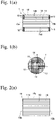
- the ceramic honeycomb structure 1 of the present invention comprises a ceramic honeycomb body 11 having large numbers of longitudinal cells 14 formed by porous cell walls 13, a peripheral wall 12 formed on a peripheral surface of the ceramic honeycomb body 11, and plugs 18 formed on both end surfaces 15a, 15b of peripheral cells 141 of the ceramic honeycomb body 11.
- the peripheral cells 141 are cells in the range of the first cell to the 7 th cell radially from the peripheral surface toward a center axis (for convenience' sake, the figure exemplifies the first cell to 3 rd cell sealed).
- An exhaust gas does not flow through the peripheral cells 141 because they are provided with the plugs 18 at both ends.
- the number of the peripheral cells 141 provided with the plugs 18 is preferably as small as possible.
- the peripheral cells 141 provided with the plugs 18 at both ends are arranged from the peripheral surface toward the center axis, preferably in a range from the first cell to the 5 th cell, more preferably in a range from the first cell to the 4 th cell, most preferably in a range from the first cell to the 2 nd cell.
- the coating material is applied preferably in a range from the first cell to at least the 2 nd cell, more preferably in a range from the first cell to the 4 th cell, from the peripheral surface toward the center axis.
- the number of cells provided with the plugs 18 and the number of cells coated with the coating material are counted from the peripheral surface (except for grooves on the peripheral surface) toward the center axis, i.e., counted in a direction in which the cell wall is perpendicular to the periphery (a direction of the arrow a or b in Fig. 1(b) ).
- the plugs 18 extend in both end portions of the peripheral cells 141 from each end surface of the ceramic honeycomb body 11 in a length of preferably 3-15 mm, more preferably 5-10 mm. All peripheral cells 141 need not have plugs 18 with the same length, but for example, plugs 18, 18a having different lengths may exist as shown in Fig. 7(c) .
- part of the plugs 18 project from the end surfaces of the peripheral cells 141, to form a coating material layer 172, by which not only adjacent plugs 18 are connected, but also the plugs 18 and the peripheral wall 12 are connected.
- the method of the present invention for producing a ceramic honeycomb structure comprising a ceramic honeycomb body having large numbers of longitudinal cells partitioned by porous cell walls, and a peripheral wall formed on a peripheral surface of the ceramic honeycomb body, comprising the steps of
- the honeycomb-structured ceramic green body is produced by extruding a moldable ceramic material. Ceramic powder is fully dry-mixed with a binder, a lubricant, and if necessary, a pore-forming material, and sufficiently blended with water to form a plasticized ceramic material. This ceramic material is extruded, cut to a predetermined length, and dried to obtain a honeycomb-structured ceramic green body integrally comprising a peripheral wall and cell walls.
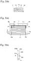
- the honeycomb-structured ceramic green body is sintered, and a peripheral portion of the resultant sintered body is machined to remove part of cell walls of peripheral cells 14a in the peripheral portion as shown in Figs. 2(a) and 2(b) , thereby forming a ceramic honeycomb body 11 having longitudinal grooves 16 on a peripheral surface 11a.
- a peripheral surface is machined after the green body is sintered, but the green body before sintering may be machined and then sintered to form the ceramic honeycomb body 11.
- Ceramic honeycomb body Materials preferable for the ceramic honeycomb body include cordierite, alumina, silica, silicon nitride, silicon carbide, aluminum titanate, LAS, etc. Among them, a ceramic honeycomb body comprising cordierite as a main crystal phase is most preferable because it is inexpensive and has excellent heat resistance and chemical stability.
- the ceramic honeycomb body 11 is coated with a coating material 17, on a peripheral surface 11a having longitudinal grooves 16, and on peripheral portions 151 of both end surfaces 15a, 15b.
- the coating material is applied preferably in a range from the first cell to at least the 2 nd cell, more preferably in a range from the first cell to the 4 th cell, from the peripheral surface toward the center axis.
- the thickness of the coating material 17 applied to the peripheral surface 11a is preferably 0.1-5 mm, more preferably 0.5-4 mm.
- the thickness of the coating material 17 applied to the peripheral portions 151 of both end surfaces 15a, 15b is preferably 3.5-15 mm, more preferably 4-13 mm.
- the coating material 17 can be applied, for example, by an applicator 20 shown in Fig. 3(a) .
- the applicator 20 comprises two disc-shaped support plates 21a, 21b sandwiching both end surfaces 15a, 15b of the ceramic honeycomb body 11, and a scraper 25 abutting the peripheral ends 213a of the support plates 21a, 21b.
- the ceramic honeycomb body 11 sandwiched by the support plates 21a, 21b can freely rotate around a center axis X.
- each support plate 21a, 21b comprises a center portion 211 coming into contact with each end surface 15a, 15b of the ceramic honeycomb body 11, and a peripheral portion 213 thinner than the center portion 211, a boundary between the center portion 211 and the peripheral portion 213 constituting a step 212 having a height L 1 , which is circular around the center axis.
- a gap having a width L 1 for applying a coating material is provided between the peripheral portion 213 of each support plate 21a, 21b and each end surface 15a, 15b of the ceramic honeycomb body 11.
- Each support plate 21a, 21b has a larger outer diameter than that of the ceramic honeycomb body 11, providing a gap for applying a coating material between the peripheral surface 11a of the ceramic honeycomb body 11 and the scraper 25 abutting the peripheral end portions 213a of the support plates 21a, 21b.
- the coating material 17 is caused to flow into a gap between the peripheral surface 11a of the ceramic honeycomb body 11 and the scraper 25, and a gap between the peripheral portion 151 of each end surface 15a, 15b and the peripheral portion 213 of each support plate 21a, 21b.
- the coating material 17 made flat by the scraper 25 is applied to the peripheral surface 11a and the peripheral portion 151 of each end surface 15a, 15b.
- the grooves 16 on the peripheral surface 11a are preferably filled with the coating material 17 without void.
- the peripheral portions 151 of both end surfaces 15a, 15b of the ceramic honeycomb body 11, to which the coating material 17 is applied can be controlled. Also, with the height L 1 of the steps 212 of the support plates 21a, 21b adjusted, the amount of the coating material 17 inserted into end portions of the peripheral cells 141 can be controlled, thereby adjusting the length of the plugs 18.
- the coating material 17 is preferably in the form of a paste having a viscosity of 20 Pa ⁇ s or more, which is obtained by blending ceramic aggregate, colloidal silica or colloidal alumina, a binder, water, and if necessary, a dispersant, etc. Too high viscosity is not preferable, because a sufficient coating material 17 cannot be easily filled into the grooves 16 on the peripheral surface 11a of the ceramic honeycomb body 11, and because the coating material 17 applied to the peripheral portions 151 of end surfaces 15a, 15b cannot be easily filled into end portions of the peripheral cells 141.
- the viscosity of the coating material 17 is more preferably 500 Pa ⁇ s or less.
- the ceramic aggregate may be cordierite, alumina, mullite, silica, aluminum titanate, etc.
- the ceramic aggregate may be the same as or different from the material of the ceramic honeycomb body.
- the coating material 17 may contain ceramic fibers, an inorganic binder, an organic binder, etc., in addition to ceramic aggregate.
- the scraper 25 and the support plates 21a, 21b are taken out of the ceramic honeycomb body 11, and the ceramic honeycomb body 11 having the coating material 17 in grooves 16 on the peripheral surface 11a and on the peripheral portions 151 of the end surfaces 15a, 15b is separated from the applicator 20.
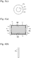
- disc-shaped pressing jigs 31a, 31b [ Fig. 4(b) ] are pressed onto the coating material 17 on the peripheral portions 151 of the end surfaces 15a, 15b of the separated ceramic honeycomb body 11, so that the coating material 17 enters the end portions of the peripheral cells 141.
- the coating material 171 entering the end portions of the peripheral cells 141 forms plugs 18 in both end portions of the peripheral cells 141, resulting in a residual coating material layer 172 on the peripheral portions 151 of the end surfaces 15a, 15b of the ceramic honeycomb body 11.
- the coating material 171 inserted into the end portions of the peripheral cells 141 fill end portions of the cells, and enter pores in the porous cell walls 13, resulting in high adhesion to the cell walls 13. Accordingly, the coating material 170 applied to grooves 16 on the peripheral surface 11a to form a peripheral wall 12, the residual coating material layer 172, the coating material 171 inserted into the cell end portions to form plugs 18, and the cell walls 13 are well adhered integrally to the ceramic honeycomb body 11. With the pressing jigs 31a, 31b designed to stop at predetermined positions from both end surfaces 15a, 15b of the ceramic honeycomb body 11, the length of the coating material 171 inserted into the end portions of the peripheral cells 141, and the thickness of the residual coating material layer 172 can be controlled.
- the thickness of the residual coating material layer 172 can be easily controlled, for example, by using disc-shaped pressing jigs 32a, 32b having a step 312 between a center portion 311 and a peripheral portion 313 as shown in Figs. 5(a) to 5(c) .
- the stepped, disc-shaped pressing jigs 32a, 32b are pressed to both end surfaces 15a, 15b of the ceramic honeycomb body 11 under a load of 0.1 MPa or more, until the end surfaces of the center portion 311 come into contact with the end surfaces 15a, 15b of the ceramic honeycomb body 11, as shown in Fig.
- the height L 2 of the step 312 of the stepped, disc-shaped pressing jigs 32a, 32b may be changed to adjust the thickness of the residual coating material layer 172.
- the pressing jigs 31a, 31b (or the stepped, disc-shaped pressing jigs 32a, 32b) are removed, and the coating material 17 is dried by a known method such as hot air drying, microwave drying, etc. to remove moisture from the coating material 17, thereby forming a peripheral wall 12 on the grooves 16 on the peripheral surface 11a, and plugs 18 in both end portions of the peripheral cells 141.
- the coating material 171 in both end portions of the peripheral cells 141 intrude into pores in the cell walls 13, so that the coating material 170 applied to the grooves 16 on the peripheral surface 11a, the residual coating material layer 172, the coating material 171 in the cell end portions, and the cell walls 13 are integrally well adhered. Accordingly, even with heat shock in drying the ceramic honeycomb body 11 coated with the coating material 17, gaps would not easily be formed between the coating material 17 and the cell walls 13 in the end portions of the peripheral wall 12, so that the end portions of the peripheral wall 12 would not be peeled or damaged in subsequent handling and use in a metal container.
- the coating material 171 is inserted to a depth of preferably 3 mm or more, more preferably 5 mm or more.
- the thickness of the residual coating material layer 172 is preferably 0.5 mm or more, more preferably 1 mm or more.
- the residual coating material layer 172 When the residual coating material layer 172 is as thick as more than 10 mm, the residual coating material layer 172 is easily broken in subsequent handling, likely acting as a breakage-starting site of the coating material 170 (peripheral wall 12) applied to the peripheral surface 11a.
- the thickness of the residual coating material layer 172 is preferably 8 mm or less, more preferably 5 mm or less.
- the cell walls 13 preferably have porosity of 40-80%.
- the residual coating material layer 172 on the peripheral portions 151 of the end surfaces 15a, 15b are projecting from both end surfaces 15a, 15b of the ceramic honeycomb body 11. Accordingly, they may be removed by grinding after drying, to form the ceramic honeycomb structure 1 shown in Figs. 1(a) and 1(b) .
- the residual coating material layer 172 is removed after drying, gaps are unlikely to generate between the end portions of the peripheral wall 12 and the grooves 13, because the coating material 17 is already dried.
- the coating material 171 need not have the same depth in the end portions of the peripheral cells 141.
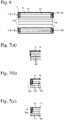
- a radially inward portion of the coating material 17 applied to the peripheral portion 151 of each end surface 15a, 15b does not cover a cell completely as shown in Fig. 7(a)
- the coating material 171 inserted into the end portions of the peripheral cells 141 does not the same depth as shown in Figs. 7(b) and 7(c) . In such case, the effects of the present invention are obtained.
- the method of the present invention is used to produce a ceramic honeycomb structure 1 having cells 141a each having one end sealed by a peripheral wall 12 as shown in Figs. 11(a) and 11(b) , the peeling and chipping of the end portions of the peripheral wall 12 can be prevented, and the sealed cells 141a provide higher heat insulation because the cells 141a are sealed by the coating material 171 at the other ends.
- the peripheral wall 12 may be heated and sintered. Both ends of each cell in the ceramic honeycomb structure 1 may be alternately plugged.
- Kaolin powder, talc powder, silica powder, and alumina powder were mixed to prepare a cordierite-forming material powder comprising 50% by mass of SiO 2 , 36% by mass of Al 2 O 3 , and 14% by mass of MgO.
- This material powder was fully dry-mixed with methylcellulose and hydroxypropyl methylcellulose as a binder, a lubricant, and a foamed resin as a pore-forming material, and sufficiently blended with water to prepare a plasticized ceramic material.
- This ceramic material was extruded, cut to a predetermined length, and dried to obtain a honeycomb-structured ceramic green body comprising a peripheral portion integral with cell walls.
- This green body was sintered, and then machined to remove part of cell walls existing in a peripheral portion, thereby obtaining a cordierite honeycomb body with longitudinal grooves on a peripheral surface, which had an outer diameter of 266 mm, a length of 305 mm, a cell wall thickness of 0.3 mm, a cell pitch of 1.57 mm, and a cell wall porosity of 61%.
- the coating material 17 was applied to a peripheral surface 11a of the ceramic honeycomb body.
- the applicator 20 comprised support plates 21a, 21b of 270 mm in outer diameter with a step 212 having a height L 1 of 6 mm.
- the distance from the step 212 to a periphery 213a was set, such that a coating material applied to a peripheral portion of each end surface 15a, 15b of the ceramic honeycomb body covers 5 cells (excluding grooves on the peripheral surface) from the periphery toward the center axis.
- the support plates 21a, 21b were removed, and disc-shaped pressing jigs 32a, 32b each having a step 312 having a height L 2 of 1 mm [see Figs. 5(b) and 5(c) ] were pressed onto both entire end surfaces of the ceramic honeycomb body 11 under a load of 0.1 MPa, to insert the coating material 17 applied to the peripheral portion 151 of each end surface 15a, 15b into cells, as shown in Fig. 5(a) .
- the coating material 17 peripheral wall 12
- the coating material 171 plugs 18
- the residual coating material layer 172 was removed by grinding from the peripheral portions 151 of the end surfaces 15a, 15b, thereby producing three ceramic honeycomb structures each having an outer diameter of 270 mm and a length of 305 mm.
- the presence of the coating material applied to peripheral portions of end surfaces, the number of cells covered by the coating material, the number of cells having the coating material inserted, the length of the coating material inserted, the thickness of the residual coating material layer 172 when dried, and the removal of the residual coating material layer 172 after drying are shown in Table 1.
- Table 1 the number of cells covered by the coating material and the number of cells having the coating material inserted (excluding grooves on the peripheral surface) were counted from the peripheral surface toward the center axis in a direction perpendicular to the periphery, which is shown by the arrow a or b in Fig. 1(b) .
- the length of the coating material inserted was measured at 10 sites in a sample cut after the evaluation test, and averaged.
- Another ceramic honeycomb structure assembled in a metal container was subject to a vibration test at 60 G and 100 Hz for 100 hours, and taken out of the metal container for observation by the naked eye.
- the breakage of the ceramic honeycomb structure in a metal container under vibration was evaluated by the following standard: Excellent: No breakage.
- Poor Suffering breakage of 1 mm or more.
- a ceramic honeycomb structure 1 having an outer diameter of 270 mm and a length of 306 mm was produced in the same manner as in Example 1, except for changing the distance from the step 212 to the periphery 213a in each support plate 21a, 21b in the applicator 20 to change the number of cells covered by a coating material applied to the peripheral portions of both end surfaces of the ceramic honeycomb body 11 (the number of cells covered by the coating material) as shown in Table 1, and evaluated in the same manner as in Example 1. The results are shown in Table 1.
- a ceramic honeycomb structure 1 having an outer diameter of 270 mm and a length of 306 mm was produced in the same manner as in Example 1, except that pressing jigs 31a, 31b each having a step 312 having a height L 2 of 0.5 mm were used, and that the residual coating material layer 172 was not removed from the peripheral portions 151 of both end surfaces 15a, 15b, and evaluated in the same manner as in Example 1. The results are shown in Table 1.
- a ceramic honeycomb structure 1 was produced in the same manner as in Example 1, except that a pore-forming material was not used in the production of the ceramic honeycomb body 11, and that the ceramic honeycomb body 11 had a cell wall thickness of 0.2 mm, a cell pitch of 1.47 mm and a cell wall porosity of 35%, and evaluated in the same manner as in Example 1. The results are shown in Table 1.
- a honeycomb-structured ceramic green body [ Fig. 8(a) ] extruded in the same manner as in Example 1 was dried on a silicon nitride table 41 having surface roughness of 300 ⁇ m. Because the table 41 was not slidable due to high surface roughness, the ceramic honeycomb body 11 was subject to smaller drying shrinkage on the side of the end surface 15b in contact with the table 41 due to friction between the table 41 and the end surface 15b, resulting in a dried, frustoconical, honeycomb-structured ceramic green body having a larger outer diameter at the end surface 15b than at the end surface 15a [ Fig. 8(b) ].
- This frustoconical, honeycomb-structured ceramic green body was sintered, with the end surface 15b having a larger outer diameter in contact with the table 41 [ Fig. 8(c) ].
- the resultant frustoconical sintered body was cylindrically machined to remove a peripheral side portion, to obtain a cordierite honeycomb body having an outer diameter of 266 mm, a length of 305 mm, a cell wall thickness of 0.3 mm, a cell pitch of 1.57 mm, and a cell wall porosity of 61% [ Fig. 8(d) ].
- this ceramic honeycomb body as shown in Fig. 8(d) , three cells existing from the periphery of the end surface 15a toward the center axis were not penetrating to the end surface 15b on the other side, but open as longitudinal grooves on the peripheral surface.
- a coating material 17 was applied to this ceramic honeycomb body 11 in the same manner as in Example 1, and the coating material 17 applied to the peripheral portion 151 of each end surface 15a, 15b was inserted into the cells as shown in Figs. 10(a) and 10(b) .
- drying was conducted with the residual coating material layer 172 remaining as in Example 1.
- the residual coating material layer 172 was removed from the end surfaces of the peripheral cells by grinding to produce a ceramic honeycomb structure 1 shown in Fig. 11(b) , and evaluated in the same manner as in Example 1. The results are shown in Table 1. Because the number of cells covered with the coating material and the number of cells having the coating material inserted were different between two end surfaces, those on both end surfaces are shown in Table 1.
- a ceramic honeycomb structure 1 having an outer diameter of 270 mm and a length of 306 mm was produced in the same manner as in Example 3 except for using support plates 21a, 21b each having a step 212 having a height L 1 of 4 mm, and evaluated in the same manner as in Example 1. The results are shown in Table 1.
- a ceramic honeycomb structure 1 having an outer diameter of 270 mm and a length of 306 mm was produced in the same manner as in Example 1, except that a coating material 21 was not applied to the end surfaces 15a, 15b of the ceramic honeycomb body 11. Because the coating material 21 was not applied to the end surfaces 15a, 15b, the insertion of the coating material 17 into cells by the stepped, disc-shaped pressing jigs 32a, 32b, and the removal of the residual coating material layer 172 were not conducted.
- the coating material 17 was applied to the peripheral surface 11a of the ceramic honeycomb body 11, using the applicator 20a shown in Fig. 14 .
- This applicator 20a comprised support plates 59a, 59b each having no step 212, in place of support plates 21a, 21b used in Example 1.
- each support plate 59a, 59b has a shape abutting an entire surface of each end surface 15a, 15b of the ceramic honeycomb body 11, with an outer diameter of 270 mm, the same as the outer diameter of each support plate 21a, 21b in the applicator 20 used in Example 1.
- the resultant ceramic honeycomb structure 1 was evaluated in the same manner as in Example 1. The results are shown in Table 1.
- a ceramic honeycomb structure 1 having an outer diameter of 270 mm and a length of 306 mm was produced in the same manner as in Example 1, except that an operation for inserting a coating material 17 applied to the peripheral portion 151 of each end surface 15a, 15b into cells was not conducted, and evaluated in the same manner as in Example 1. The results are shown in Table 1.
- the coating material 17 applied to the end surfaces of the peripheral cells 141 and dried was removed by grinding, like the residual coating material layer 172 in Example 1.
- the ceramic honeycomb structure of Comparative Example 1 in which a coating material was not applied to peripheral portions of both end surfaces of the ceramic honeycomb body, suffers gaps between end portions of the peripheral wall and the peripheral surface, with much peeling and chipping on the peripheral wall.
- Comparative Example 2 in which a coating material was applied to peripheral portions of both end surfaces of the ceramic honeycomb body, but not inserted into cells, the coating material is not sufficiently adhered to both end surfaces of the ceramic honeycomb body, resulting in gaps between end portions of the peripheral wall and the peripheral surface, with much peeling and chipping on the peripheral wall.
- a coating material is applied not only to a peripheral surface of the ceramic honeycomb body, but also to peripheral portions of both end surfaces of the ceramic honeycomb body, with a coating material on both end surfaces inserted into cells, gaps are unlikely generated between the peripheral wall and the grooves when dried, resulting in a ceramic honeycomb structure not suffering peeling and chipping from the gap in end portions of the peripheral wall in subsequent handling and use in a metal container, and free from damage from this defect in the peripheral wall.
Landscapes
- Chemical & Material Sciences (AREA)
- Engineering & Computer Science (AREA)
- Ceramic Engineering (AREA)
- Structural Engineering (AREA)
- Materials Engineering (AREA)
- Organic Chemistry (AREA)
- Chemical Kinetics & Catalysis (AREA)
- Physics & Mathematics (AREA)
- Geometry (AREA)
- Mechanical Engineering (AREA)
- Inorganic Chemistry (AREA)
- Geology (AREA)
- Life Sciences & Earth Sciences (AREA)
- Filtering Materials (AREA)
- Devices For Post-Treatments, Processing, Supply, Discharge, And Other Processes (AREA)
- Exhaust Gas After Treatment (AREA)
- Catalysts (AREA)
- Manufacturing & Machinery (AREA)
- Porous Artificial Stone Or Porous Ceramic Products (AREA)
Claims (4)
- Procédé destiné à la production d'une structure en nid d'abeille céramique (1) comprenant un corps en nid d'abeille céramique (11) ayant un grand nombre de cellules longitudinales (14) séparées par des parois cellulaires poreuses (13) et une paroi périphérique (12) formée sur une surface périphérique (11a) dudit corps en nid d'abeille céramique (11), comprenant les étapes d'extrusion d'un matériau céramique moulable pour former un corps cru céramique ayant une structure en nid d'abeille ;l'usinage d'une partie périphérique dudit corps cru ou d'un corps fritté obtenu à partir dudit corps cru pour enlever une partie des parois cellulaires dans la partie périphérique, obtenant ainsi ledit corps en nid d'abeille céramique (11) ayant des rainures longitudinales (16) sur la surface périphérique (11a) ; l'application d'un matériau de revêtement (17) sur la surface périphérique (11a) dudit corps en nid d'abeille céramique (11) pour former ladite paroi périphérique (12), ainsi que sur les parties périphériques (151) des deux surfaces d'extrémité (15a, 15b) dudit corps en nid d'abeille céramique (11) ; et l'insertion du matériau de revêtement (17) appliqué sur lesdites parties périphériques (151) des deux surfaces d'extrémité (15a, 15b) dans des cellules périphériques (141),caractérisé en ce que le matériau de revêtement (17) appliqué sur lesdites parties périphériques (151) des deux surfaces d'extrémité (15a, 15b) est pressé par des gabarits de pressage en forme de disque, de sorte que ledit matériau de revêtement (17) pénètre dans les parties d'extrémité des cellules périphériques (141) pour former des bouchons (18, 171) et des couches de matériau de revêtement résiduelles (172) restant sur les parties périphériques (151) reliant intégralement les bouchons (18, 171) et la paroi périphérique (12, 170).
- Procédé destiné à la production d'une structure en nid d'abeille céramique (1) selon la revendication 1, la couche de matériau de revêtement résiduelle (172) restant sur les parties périphériques (151) des deux surfaces d'extrémité (15a, 15b) et ayant une épaisseur égale ou supérieure à 1 mm étant enlevée après le séchage de ladite couche de matériau de revêtement résiduelle (172).
- Structure en nid d'abeille céramiques (1) comprenant un corps en nid d'abeille céramique (11) ayant un grand nombre de cellules longitudinales (14) séparées par des parois cellulaires poreuses (13), une paroi périphérique (12) formée par un matériau de revêtement (17) appliqué sur un surface périphérique (11a) dudit corps en nid d'abeille céramique (11), des bouchons (18, 171) formés par le matériau de revêtement (17) insérés dans les deux parties d'extrémité des cellules (141) dans une partie périphérique (151) dudit corps en nid d'abeille céramique (11) et des couches de matériau de revêtement résiduelles (172) restant sur les parties périphériques (151) des deux surfaces d'extrémité (15a, 15b) reliant intégralement les bouchons (18, 171) et la paroi périphérique (12, 170).
- Structure en nid d'abeille céramique (1) produite par un procédé défini dans la revendication 2, comprenant un corps en nid d'abeille céramique (11) ayant un grand nombre de cellules longitudinales (14) séparées par des parois cellulaires poreuses (13), une paroi périphérique (12) formée par un matériau de revêtement (17) appliqué sur une surface périphérique (11a) dudit corps en nid d'abeille céramique (11) et des bouchons (18, 171) formés par le matériau de revêtement (17) inséré dans les deux parties d'extrémité des cellules (141) dans une partie périphérique (151) dudit corps en nid d'abeille céramique (11), caractérisé en ce que ledit corps en nid d'abeille céramique (11) a des rainures longitudinales (16) sur la surface périphérique (11a), en ce que ladite partie périphérique (151) ayant les bouchons (18, 171) est dans une plage allant de la première cellule à au moins la 2e cellule depuis la surface périphérique (11a) vers un axe central (X) et en ce qu'un espace entre les parties d'extrémité de la paroi périphérique et la surface périphérique est inférieur à 0,5 mm comportant aucun espace pour la structure en nid d'abeille céramique découpée pour l'observation à l'œil nu.
Applications Claiming Priority (3)
| Application Number | Priority Date | Filing Date | Title |
|---|---|---|---|
| JP2011224019 | 2011-10-11 | ||
| JP2012075616 | 2012-03-29 | ||
| PCT/JP2012/074270 WO2013054651A1 (fr) | 2011-10-11 | 2012-09-21 | Procédé de fabrication d'une structure en nid d'abeilles céramique et structure en nid d'abeilles céramique |
Publications (3)
| Publication Number | Publication Date |
|---|---|
| EP2767528A1 EP2767528A1 (fr) | 2014-08-20 |
| EP2767528A4 EP2767528A4 (fr) | 2015-05-27 |
| EP2767528B1 true EP2767528B1 (fr) | 2022-08-24 |
Family
ID=48081708
Family Applications (1)
| Application Number | Title | Priority Date | Filing Date |
|---|---|---|---|
| EP12840519.8A Active EP2767528B1 (fr) | 2011-10-11 | 2012-09-21 | Procédé de fabrication d'une structure en nid d'abeilles céramique et structure en nid d'abeilles céramique |
Country Status (5)
| Country | Link |
|---|---|
| US (1) | US9950964B2 (fr) |
| EP (1) | EP2767528B1 (fr) |
| JP (1) | JP6075291B2 (fr) |
| CN (2) | CN103889928B (fr) |
| WO (1) | WO2013054651A1 (fr) |
Families Citing this family (11)
| Publication number | Priority date | Publication date | Assignee | Title |
|---|---|---|---|---|
| EP2698190B1 (fr) * | 2012-08-13 | 2018-06-27 | NGK Insulators, Ltd. | Structure en nid d'abeille raccordée |
| US9028741B1 (en) * | 2013-03-15 | 2015-05-12 | Ibiden Co., Ltd. | Method for manufacturing aluminum-titanate-based ceramic honeycomb structure |
| JP6389134B2 (ja) * | 2015-03-20 | 2018-09-12 | 日本碍子株式会社 | 目封止ハニカム構造体の製造方法、及び目封止ハニカム構造体 |
| JP6581917B2 (ja) * | 2016-02-19 | 2019-09-25 | 日本碍子株式会社 | ハニカム構造体 |
| USD972698S1 (en) | 2016-06-20 | 2022-12-13 | 3M Innovative Properties Company | Air filter |
| CN107327333B (zh) * | 2017-07-11 | 2018-05-22 | 广州恒尚科技有限公司 | 三元催化器及其制备方法 |
| EP4570778A1 (fr) | 2018-08-31 | 2025-06-18 | Corning Incorporated | Procédés de fabrication de corps en nid d'abeilles ayant des dépôts de filtration inorganiques |
| JP2021536422A (ja) * | 2018-08-31 | 2021-12-27 | コーニング インコーポレイテッド | 無機濾過堆積物を有するハニカム体の製造方法 |
| MX2021002538A (es) | 2018-09-03 | 2021-07-21 | Corning Inc | Cuerpo de panal con material poroso. |
| JP2020157260A (ja) * | 2019-03-27 | 2020-10-01 | 日本碍子株式会社 | ハニカム構造体の製造方法 |
| JP2024093494A (ja) * | 2022-12-27 | 2024-07-09 | 株式会社キャタラー | 排ガス浄化用触媒の製造方法 |
Citations (1)
| Publication number | Priority date | Publication date | Assignee | Title |
|---|---|---|---|---|
| EP1580181A2 (fr) * | 2004-03-24 | 2005-09-28 | Ngk Insulators, Ltd. | Structure en nid d'abeille et procédé de sa fabrication |
Family Cites Families (11)
| Publication number | Priority date | Publication date | Assignee | Title |
|---|---|---|---|---|
| US5219667A (en) * | 1991-12-12 | 1993-06-15 | Corning Incorporated | Honeycomb structure and method of forming |
| JP2613729B2 (ja) | 1992-01-30 | 1997-05-28 | 日本碍子株式会社 | セラミックハニカム構造体及びその製造法並びにそのためのコート材 |
| US5629067A (en) | 1992-01-30 | 1997-05-13 | Ngk Insulators, Ltd. | Ceramic honeycomb structure with grooves and outer coating, process of producing the same, and coating material used in the honeycomb structure |
| JP4282941B2 (ja) | 2002-03-27 | 2009-06-24 | 日本碍子株式会社 | ハニカム構造体及びその製造方法、並びにそれを使用した触媒体 |
| JP2004154768A (ja) | 2002-10-15 | 2004-06-03 | Denso Corp | 排ガス浄化フィルタ及びその製造方法 |
| JPWO2007097056A1 (ja) * | 2006-02-23 | 2009-07-09 | イビデン株式会社 | ハニカム構造体および排ガス浄化装置 |
| CN101489678A (zh) | 2006-06-23 | 2009-07-22 | 日本碍子株式会社 | 蜂窝结构体及其制造方法 |
| EP2078553B1 (fr) * | 2006-09-29 | 2013-02-27 | Hitachi Metals, Ltd. | Procédé de fabrication d'un filtre céramique en nid d'abeilles de cordiérite |
| US8728607B2 (en) * | 2006-12-27 | 2014-05-20 | Hitachi Metals, Ltd. | Ceramic honeycomb structure and its production method |
| US8268401B2 (en) | 2007-03-26 | 2012-09-18 | Hitachi Metals, Ltd. | Method for producing ceramic honeycomb structure |
| CN102089058B (zh) * | 2008-07-28 | 2014-03-12 | 日立金属株式会社 | 陶瓷蜂窝结构体及其制造方法 |
-
2012
- 2012-09-21 EP EP12840519.8A patent/EP2767528B1/fr active Active
- 2012-09-21 CN CN201280050060.3A patent/CN103889928B/zh active Active
- 2012-09-21 CN CN201810414443.3A patent/CN108582434B/zh active Active
- 2012-09-21 WO PCT/JP2012/074270 patent/WO2013054651A1/fr not_active Ceased
- 2012-09-21 US US14/350,708 patent/US9950964B2/en active Active
- 2012-09-21 JP JP2013538485A patent/JP6075291B2/ja active Active
Patent Citations (1)
| Publication number | Priority date | Publication date | Assignee | Title |
|---|---|---|---|---|
| EP1580181A2 (fr) * | 2004-03-24 | 2005-09-28 | Ngk Insulators, Ltd. | Structure en nid d'abeille et procédé de sa fabrication |
Also Published As
| Publication number | Publication date |
|---|---|
| CN103889928A (zh) | 2014-06-25 |
| US20140248464A1 (en) | 2014-09-04 |
| EP2767528A4 (fr) | 2015-05-27 |
| CN103889928B (zh) | 2019-04-09 |
| WO2013054651A1 (fr) | 2013-04-18 |
| CN108582434B (zh) | 2020-05-19 |
| JPWO2013054651A1 (ja) | 2015-03-30 |
| EP2767528A1 (fr) | 2014-08-20 |
| JP6075291B2 (ja) | 2017-02-08 |
| US9950964B2 (en) | 2018-04-24 |
| CN108582434A (zh) | 2018-09-28 |
Similar Documents
| Publication | Publication Date | Title |
|---|---|---|
| EP2767528B1 (fr) | Procédé de fabrication d'une structure en nid d'abeilles céramique et structure en nid d'abeilles céramique | |
| US8323557B2 (en) | Method for manufacturing honeycomb structure | |
| EP1978006B1 (fr) | Filtre en nid d'abeille | |
| CN103889929B (zh) | 陶瓷蜂窝结构体的制造方法和陶瓷蜂窝结构体 | |
| CN103458990B (zh) | 封孔蜂窝结构体 | |
| US8153073B2 (en) | Honeycomb filter, exhaust gas purifying apparatus and method for manufacturing honeycomb filter | |
| EP2008985A1 (fr) | Element raccord, element raccord d'un segment en nid d'abeille et structure en nid d'abeille ainsi obtenue | |
| US20070068128A1 (en) | Honeycomb structure and manufacturing method for honeycomb structure | |
| EP1997789A1 (fr) | Structure en nid d'abeille et materiau de liaison a utiliser pour celle-ci | |
| EP2090414A2 (fr) | Procédé de fabrication d'un élément structuré en nid d'abeille | |
| CN101274293A (zh) | 蜂窝结构体和排气处理设备 | |
| EP2008987B1 (fr) | Corps à structure en nid d'abeille | |
| EP2698191B1 (fr) | Structure en nid d'abeille raccordée | |
| EP2123617A1 (fr) | Composition de matière de liaison, procédé de fabrication de la composition de matière de liaison, article assemblé et procédé de fabrication de l'article assemblé | |
| EP2233454B1 (fr) | Structure en nid d'abeille | |
| EP2221099B1 (fr) | Structure en nid d'abeille | |
| JP2011190740A (ja) | ハニカム構造体 | |
| EP1757351B1 (fr) | Structure en nid d'abeilles et sa fabrication | |
| JP2009214098A (ja) | ハニカム構造体、排ガス浄化装置、及び、ハニカム構造体の製造方法 | |
| EP2067515B1 (fr) | Procédés de fabrication d'un filtre céramique en nid d'abeilles | |
| JP2007117829A (ja) | ハニカム構造体 |
Legal Events
| Date | Code | Title | Description |
|---|---|---|---|
| PUAI | Public reference made under article 153(3) epc to a published international application that has entered the european phase |
Free format text: ORIGINAL CODE: 0009012 |
|
| 17P | Request for examination filed |
Effective date: 20140415 |
|
| AK | Designated contracting states |
Kind code of ref document: A1 Designated state(s): AL AT BE BG CH CY CZ DE DK EE ES FI FR GB GR HR HU IE IS IT LI LT LU LV MC MK MT NL NO PL PT RO RS SE SI SK SM TR |
|
| DAX | Request for extension of the european patent (deleted) | ||
| RA4 | Supplementary search report drawn up and despatched (corrected) |
Effective date: 20150430 |
|
| RIC1 | Information provided on ipc code assigned before grant |
Ipc: B01D 46/00 20060101ALI20150423BHEP Ipc: B01J 35/04 20060101ALI20150423BHEP Ipc: B01D 39/20 20060101ALI20150423BHEP Ipc: C04B 41/85 20060101AFI20150423BHEP Ipc: B28B 11/04 20060101ALI20150423BHEP Ipc: F01N 3/02 20060101ALI20150423BHEP Ipc: B01J 37/02 20060101ALI20150423BHEP Ipc: C04B 38/00 20060101ALI20150423BHEP Ipc: F01N 3/28 20060101ALI20150423BHEP |
|
| STAA | Information on the status of an ep patent application or granted ep patent |
Free format text: STATUS: EXAMINATION IS IN PROGRESS |
|
| 17Q | First examination report despatched |
Effective date: 20180410 |
|
| GRAP | Despatch of communication of intention to grant a patent |
Free format text: ORIGINAL CODE: EPIDOSNIGR1 |
|
| STAA | Information on the status of an ep patent application or granted ep patent |
Free format text: STATUS: GRANT OF PATENT IS INTENDED |
|
| INTG | Intention to grant announced |
Effective date: 20220405 |
|
| GRAS | Grant fee paid |
Free format text: ORIGINAL CODE: EPIDOSNIGR3 |
|
| GRAA | (expected) grant |
Free format text: ORIGINAL CODE: 0009210 |
|
| STAA | Information on the status of an ep patent application or granted ep patent |
Free format text: STATUS: THE PATENT HAS BEEN GRANTED |
|
| AK | Designated contracting states |
Kind code of ref document: B1 Designated state(s): AL AT BE BG CH CY CZ DE DK EE ES FI FR GB GR HR HU IE IS IT LI LT LU LV MC MK MT NL NO PL PT RO RS SE SI SK SM TR |
|
| REG | Reference to a national code |
Ref country code: GB Ref legal event code: FG4D |
|
| REG | Reference to a national code |
Ref country code: CH Ref legal event code: EP |
|
| REG | Reference to a national code |
Ref country code: IE Ref legal event code: FG4D |
|
| REG | Reference to a national code |
Ref country code: AT Ref legal event code: REF Ref document number: 1513569 Country of ref document: AT Kind code of ref document: T Effective date: 20220915 Ref country code: DE Ref legal event code: R096 Ref document number: 602012078660 Country of ref document: DE |
|
| REG | Reference to a national code |
Ref country code: LT Ref legal event code: MG9D |
|
| REG | Reference to a national code |
Ref country code: NL Ref legal event code: MP Effective date: 20220824 |
|
| PG25 | Lapsed in a contracting state [announced via postgrant information from national office to epo] |
Ref country code: SE Free format text: LAPSE BECAUSE OF FAILURE TO SUBMIT A TRANSLATION OF THE DESCRIPTION OR TO PAY THE FEE WITHIN THE PRESCRIBED TIME-LIMIT Effective date: 20220824 Ref country code: RS Free format text: LAPSE BECAUSE OF FAILURE TO SUBMIT A TRANSLATION OF THE DESCRIPTION OR TO PAY THE FEE WITHIN THE PRESCRIBED TIME-LIMIT Effective date: 20220824 Ref country code: PT Free format text: LAPSE BECAUSE OF FAILURE TO SUBMIT A TRANSLATION OF THE DESCRIPTION OR TO PAY THE FEE WITHIN THE PRESCRIBED TIME-LIMIT Effective date: 20221226 Ref country code: NO Free format text: LAPSE BECAUSE OF FAILURE TO SUBMIT A TRANSLATION OF THE DESCRIPTION OR TO PAY THE FEE WITHIN THE PRESCRIBED TIME-LIMIT Effective date: 20221124 Ref country code: NL Free format text: LAPSE BECAUSE OF FAILURE TO SUBMIT A TRANSLATION OF THE DESCRIPTION OR TO PAY THE FEE WITHIN THE PRESCRIBED TIME-LIMIT Effective date: 20220824 Ref country code: LV Free format text: LAPSE BECAUSE OF FAILURE TO SUBMIT A TRANSLATION OF THE DESCRIPTION OR TO PAY THE FEE WITHIN THE PRESCRIBED TIME-LIMIT Effective date: 20220824 Ref country code: LT Free format text: LAPSE BECAUSE OF FAILURE TO SUBMIT A TRANSLATION OF THE DESCRIPTION OR TO PAY THE FEE WITHIN THE PRESCRIBED TIME-LIMIT Effective date: 20220824 Ref country code: FI Free format text: LAPSE BECAUSE OF FAILURE TO SUBMIT A TRANSLATION OF THE DESCRIPTION OR TO PAY THE FEE WITHIN THE PRESCRIBED TIME-LIMIT Effective date: 20220824 Ref country code: ES Free format text: LAPSE BECAUSE OF FAILURE TO SUBMIT A TRANSLATION OF THE DESCRIPTION OR TO PAY THE FEE WITHIN THE PRESCRIBED TIME-LIMIT Effective date: 20220824 |
|
| REG | Reference to a national code |
Ref country code: AT Ref legal event code: MK05 Ref document number: 1513569 Country of ref document: AT Kind code of ref document: T Effective date: 20220824 |
|
| PG25 | Lapsed in a contracting state [announced via postgrant information from national office to epo] |
Ref country code: PL Free format text: LAPSE BECAUSE OF FAILURE TO SUBMIT A TRANSLATION OF THE DESCRIPTION OR TO PAY THE FEE WITHIN THE PRESCRIBED TIME-LIMIT Effective date: 20220824 Ref country code: IS Free format text: LAPSE BECAUSE OF FAILURE TO SUBMIT A TRANSLATION OF THE DESCRIPTION OR TO PAY THE FEE WITHIN THE PRESCRIBED TIME-LIMIT Effective date: 20221224 Ref country code: HR Free format text: LAPSE BECAUSE OF FAILURE TO SUBMIT A TRANSLATION OF THE DESCRIPTION OR TO PAY THE FEE WITHIN THE PRESCRIBED TIME-LIMIT Effective date: 20220824 Ref country code: GR Free format text: LAPSE BECAUSE OF FAILURE TO SUBMIT A TRANSLATION OF THE DESCRIPTION OR TO PAY THE FEE WITHIN THE PRESCRIBED TIME-LIMIT Effective date: 20221125 |
|
| PG25 | Lapsed in a contracting state [announced via postgrant information from national office to epo] |
Ref country code: SM Free format text: LAPSE BECAUSE OF FAILURE TO SUBMIT A TRANSLATION OF THE DESCRIPTION OR TO PAY THE FEE WITHIN THE PRESCRIBED TIME-LIMIT Effective date: 20220824 Ref country code: RO Free format text: LAPSE BECAUSE OF FAILURE TO SUBMIT A TRANSLATION OF THE DESCRIPTION OR TO PAY THE FEE WITHIN THE PRESCRIBED TIME-LIMIT Effective date: 20220824 Ref country code: DK Free format text: LAPSE BECAUSE OF FAILURE TO SUBMIT A TRANSLATION OF THE DESCRIPTION OR TO PAY THE FEE WITHIN THE PRESCRIBED TIME-LIMIT Effective date: 20220824 Ref country code: CZ Free format text: LAPSE BECAUSE OF FAILURE TO SUBMIT A TRANSLATION OF THE DESCRIPTION OR TO PAY THE FEE WITHIN THE PRESCRIBED TIME-LIMIT Effective date: 20220824 Ref country code: AT Free format text: LAPSE BECAUSE OF FAILURE TO SUBMIT A TRANSLATION OF THE DESCRIPTION OR TO PAY THE FEE WITHIN THE PRESCRIBED TIME-LIMIT Effective date: 20220824 |
|
| REG | Reference to a national code |
Ref country code: CH Ref legal event code: PL |
|
| REG | Reference to a national code |
Ref country code: DE Ref legal event code: R097 Ref document number: 602012078660 Country of ref document: DE Ref country code: BE Ref legal event code: MM Effective date: 20220930 |
|
| PG25 | Lapsed in a contracting state [announced via postgrant information from national office to epo] |
Ref country code: SK Free format text: LAPSE BECAUSE OF FAILURE TO SUBMIT A TRANSLATION OF THE DESCRIPTION OR TO PAY THE FEE WITHIN THE PRESCRIBED TIME-LIMIT Effective date: 20220824 Ref country code: MC Free format text: LAPSE BECAUSE OF FAILURE TO SUBMIT A TRANSLATION OF THE DESCRIPTION OR TO PAY THE FEE WITHIN THE PRESCRIBED TIME-LIMIT Effective date: 20220824 Ref country code: EE Free format text: LAPSE BECAUSE OF FAILURE TO SUBMIT A TRANSLATION OF THE DESCRIPTION OR TO PAY THE FEE WITHIN THE PRESCRIBED TIME-LIMIT Effective date: 20220824 |
|
| PG25 | Lapsed in a contracting state [announced via postgrant information from national office to epo] |
Ref country code: LU Free format text: LAPSE BECAUSE OF NON-PAYMENT OF DUE FEES Effective date: 20220921 Ref country code: AL Free format text: LAPSE BECAUSE OF FAILURE TO SUBMIT A TRANSLATION OF THE DESCRIPTION OR TO PAY THE FEE WITHIN THE PRESCRIBED TIME-LIMIT Effective date: 20220824 |
|
| PLBE | No opposition filed within time limit |
Free format text: ORIGINAL CODE: 0009261 |
|
| STAA | Information on the status of an ep patent application or granted ep patent |
Free format text: STATUS: NO OPPOSITION FILED WITHIN TIME LIMIT |
|
| GBPC | Gb: european patent ceased through non-payment of renewal fee |
Effective date: 20221124 |
|
| PG25 | Lapsed in a contracting state [announced via postgrant information from national office to epo] |
Ref country code: LI Free format text: LAPSE BECAUSE OF NON-PAYMENT OF DUE FEES Effective date: 20220930 Ref country code: IE Free format text: LAPSE BECAUSE OF NON-PAYMENT OF DUE FEES Effective date: 20220921 Ref country code: FR Free format text: LAPSE BECAUSE OF NON-PAYMENT OF DUE FEES Effective date: 20221024 Ref country code: CH Free format text: LAPSE BECAUSE OF NON-PAYMENT OF DUE FEES Effective date: 20220930 |
|
| 26N | No opposition filed |
Effective date: 20230525 |
|
| PG25 | Lapsed in a contracting state [announced via postgrant information from national office to epo] |
Ref country code: SI Free format text: LAPSE BECAUSE OF FAILURE TO SUBMIT A TRANSLATION OF THE DESCRIPTION OR TO PAY THE FEE WITHIN THE PRESCRIBED TIME-LIMIT Effective date: 20220824 |
|
| PG25 | Lapsed in a contracting state [announced via postgrant information from national office to epo] |
Ref country code: BE Free format text: LAPSE BECAUSE OF NON-PAYMENT OF DUE FEES Effective date: 20220930 |
|
| PG25 | Lapsed in a contracting state [announced via postgrant information from national office to epo] |
Ref country code: GB Free format text: LAPSE BECAUSE OF NON-PAYMENT OF DUE FEES Effective date: 20221124 |
|
| PG25 | Lapsed in a contracting state [announced via postgrant information from national office to epo] |
Ref country code: HU Free format text: LAPSE BECAUSE OF FAILURE TO SUBMIT A TRANSLATION OF THE DESCRIPTION OR TO PAY THE FEE WITHIN THE PRESCRIBED TIME-LIMIT; INVALID AB INITIO Effective date: 20120921 |
|
| PG25 | Lapsed in a contracting state [announced via postgrant information from national office to epo] |
Ref country code: CY Free format text: LAPSE BECAUSE OF FAILURE TO SUBMIT A TRANSLATION OF THE DESCRIPTION OR TO PAY THE FEE WITHIN THE PRESCRIBED TIME-LIMIT Effective date: 20220824 |
|
| PG25 | Lapsed in a contracting state [announced via postgrant information from national office to epo] |
Ref country code: MK Free format text: LAPSE BECAUSE OF FAILURE TO SUBMIT A TRANSLATION OF THE DESCRIPTION OR TO PAY THE FEE WITHIN THE PRESCRIBED TIME-LIMIT Effective date: 20220824 Ref country code: IT Free format text: LAPSE BECAUSE OF FAILURE TO SUBMIT A TRANSLATION OF THE DESCRIPTION OR TO PAY THE FEE WITHIN THE PRESCRIBED TIME-LIMIT Effective date: 20220824 |
|
| PG25 | Lapsed in a contracting state [announced via postgrant information from national office to epo] |
Ref country code: BG Free format text: LAPSE BECAUSE OF FAILURE TO SUBMIT A TRANSLATION OF THE DESCRIPTION OR TO PAY THE FEE WITHIN THE PRESCRIBED TIME-LIMIT Effective date: 20220824 |
|
| PG25 | Lapsed in a contracting state [announced via postgrant information from national office to epo] |
Ref country code: MT Free format text: LAPSE BECAUSE OF FAILURE TO SUBMIT A TRANSLATION OF THE DESCRIPTION OR TO PAY THE FEE WITHIN THE PRESCRIBED TIME-LIMIT Effective date: 20220824 |
|
| REG | Reference to a national code |
Ref country code: DE Ref legal event code: R081 Ref document number: 602012078660 Country of ref document: DE Owner name: PROTERIAL, LTD., JP Free format text: FORMER OWNER: HITACHI METALS, LTD., TOKYO, JP |
|
| PGFP | Annual fee paid to national office [announced via postgrant information from national office to epo] |
Ref country code: DE Payment date: 20250730 Year of fee payment: 14 |
|
| PG25 | Lapsed in a contracting state [announced via postgrant information from national office to epo] |
Ref country code: TR Free format text: LAPSE BECAUSE OF FAILURE TO SUBMIT A TRANSLATION OF THE DESCRIPTION OR TO PAY THE FEE WITHIN THE PRESCRIBED TIME-LIMIT Effective date: 20220824 |